US6387099B1 - Surgical cable crimp - Google Patents
Surgical cable crimpDownload PDFInfo
- Publication number
- US6387099B1 US6387099B1US09/534,346US53434600AUS6387099B1US 6387099 B1US6387099 B1US 6387099B1US 53434600 AUS53434600 AUS 53434600AUS 6387099 B1US6387099 B1US 6387099B1
- Authority
- US
- United States
- Prior art keywords
- cable
- crimp member
- leg
- crimp
- channel
- Prior art date
- Legal status (The legal status is an assumption and is not a legal conclusion. Google has not performed a legal analysis and makes no representation as to the accuracy of the status listed.)
- Expired - Fee Related
Links
Images


Classifications
- A—HUMAN NECESSITIES
- A61—MEDICAL OR VETERINARY SCIENCE; HYGIENE
- A61B—DIAGNOSIS; SURGERY; IDENTIFICATION
- A61B17/00—Surgical instruments, devices or methods
- A61B17/56—Surgical instruments or methods for treatment of bones or joints; Devices specially adapted therefor
- A61B17/58—Surgical instruments or methods for treatment of bones or joints; Devices specially adapted therefor for osteosynthesis, e.g. bone plates, screws or setting implements
- A61B17/68—Internal fixation devices, including fasteners and spinal fixators, even if a part thereof projects from the skin
- A61B17/82—Internal fixation devices, including fasteners and spinal fixators, even if a part thereof projects from the skin for bone cerclage
- Y—GENERAL TAGGING OF NEW TECHNOLOGICAL DEVELOPMENTS; GENERAL TAGGING OF CROSS-SECTIONAL TECHNOLOGIES SPANNING OVER SEVERAL SECTIONS OF THE IPC; TECHNICAL SUBJECTS COVERED BY FORMER USPC CROSS-REFERENCE ART COLLECTIONS [XRACs] AND DIGESTS
- Y10—TECHNICAL SUBJECTS COVERED BY FORMER USPC
- Y10T—TECHNICAL SUBJECTS COVERED BY FORMER US CLASSIFICATION
- Y10T24/00—Buckles, buttons, clasps, etc.
- Y10T24/39—Cord and rope holders
- Y10T24/398—Bendable, ductible
Definitions
- the present inventionis directed to an orthopedic instrument in general, and in particular to a fastening or crimping device for use with surgical cables in fixation of bones during surgeries for fractured bone or bone reconstruction.
- Surgical cable and crimp assembliesare frequently used for this purpose.
- the cablesare used to encircle the bone, or bone and plate, to provide for fixation.
- a fastening devicetypically a crimp device which is adapted to be deformed upon the cable for securing the cable in place, encircling the bone in the fracture area.
- Such assembliescan be subjected to very high tensile forces when, for example, the fractured bone is subjected to a high bending moment. It is therefore important that the cable and crimp assembly have sufficient strength to prevent cable failure under tensile force.
- the cablemust be used in a subcutaneous confined area.
- the cable and crimp assemblybe easy to assemble in such a restricted area.
- easy access to the crimp deviceto facilitate crimping.
- Easy cable accessis also desirable to provide room for the application of a tension tool to tighten the cable around the bone.
- a wide variety of devices for crimping a surgical wireare known in the art. Examples of such crimp devices include those described in U.S. Pat. No. 5,810,825 issued to Huebner, U.S. Pat. Nos. 5,868,748 and 5,720,747 to Burke. Although these devices are quite successful from a technical point-of-view in achieving the desired crimping of surgical wire, most of existing devices have practical limitations. For example, most crimping devices maintain the surgical wire or cable parallel to itself in the fastening or crimping member which makes it difficult to access the free end of the cable and tighten around the bone.
- some crimping devicesrequire that the entire fastening or crimping member be crimped in order to secure the surgical wire thereto, necessitating a larger access area to permit a crimping tool to access the entire fastening or crimping member.
- crimp deviceswhich are substantially “L” shaped and maintain the surgical wire or cable at a 90° angle to itself as it leaves the fastening or crimping member. Maintaining the cable at such a steep angle can put a kink in the cable at that location and increase the likelihood that the cable will break. Furthermore, when the crimping member maintains the cable at a 90° angle, it is more difficult to insert the cable through the crimp member.
- the present inventionis directed to a surgical fastener device for fixing bone elements comprising a flexible cable having first and second ends attached to a crimp member.
- the crimp memberhas first and second portions extending between front and rear ends. First and second portions are spaced farthest apart at the rear end to form a wedge-shaped. Additionally, a channel extends through the second portion. The first end of the cable is fixedly secured to the first portion at the rear end, and the second end of the cable is insertable through the channel of the second portion for forming a loop of adjustable diameter.
- the front and rear ends of the crimp memberare rounded and the front end of the crimp member can have a smaller arc length than the rear end.
- the front end of the crimp memberis solid and the rear end has a longitudinal slot.
- the crimp memberhas an open central portion that forms a substantially triangular cutout.
- the second end of the cablehas a leader to facilitate handling.
- the cableis multi-stranded.
- first and second portions of the crimp memberare coplanar.
- the present inventionis further directed to a surgical fastener device for crimping surgical cable.
- the deviceincludes a crimp member comprising a wedge-like body having first and second parallel major surfaces vertically interconnected by a peripheral edge.
- the bodyhas a centrally disposed triangular opening vertically extending through the body from the first major surface to the second major surface.
- the bodyalso has a pair of channels extending longitudinally through the body. The channels are disposed at a non-parallel angle with respect to each other.
- the devicefurther includes a flexible cable secured to one of the channels of the crimp member.
- the cablehas first and second ends and one end is fixedly attached to the crimp member and the other end is insertable through the other channel for forming a loop of adjustable diameter.
- the cablecan be multi-stranded and the insertable end can have a leader to facilitate handling.
- the present inventionis also directed to a surgical fastening device comprising a cable having a free end and a fixed end attached to a crimp member.
- the crimp memberhas a first leg with first and second ends. The first end has a blind hole for receiving the fixed end of the cable.
- the crimp memberalso has a second leg with first and second ends. The second leg has a through bore extending from the first end to the second end of the second leg.
- the crimp memberalso has a front bridging portion connecting the second end of the first leg to the second end of the second leg.
- the crimp memberalso has a rear bridging portion connecting the first end of the first leg to the first end of the second leg.
- the rear bridging portionis longer than the front bridging portion so that the crimp member has a wedge-shape.
- the second legis crimpable so that the cable is crimped to the crimp member after the free end is inserted in the through bore.
- the cableis multi-stranded and the free end has a leader to facilitate handling.
- FIG. 1is a top view of a surgical crimp device according to the present invention showing a flexible cable and a crimp member;
- FIG. 2is a perspective view of the crimp member of FIG. 1 prior to assembly with the cable;
- FIG. 3is a top view of the crimp member of FIG. 2 with a cutaway showing cross sections of internal channels therein;
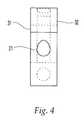
- FIG. 4is a front view of the crimp member of FIG. 2;
- FIG. 5is a back view of the crimp member of FIG. 2;
- FIG. 6is a magnified view of FIG. 1 with an enlargement of the first end of the cable
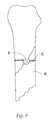
- FIG. 7is a side view of the surgical crimp device of FIG. 1 after the device has been crimped around a bone;
- FIG. 8is a side view of the surgical crimp device of FIG. 7 showing the crimp member in a low profile position;
- FIG. 9is a top view of the surgical crimp device of FIG. 8.
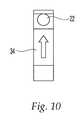
- FIG. 10is a side view of the crimp member of FIG. 2;
- FIG. 11a top view of an alternative embodiment of the surgical crimp device
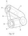
- FIG. 12is a perspective view of an alternative embodiment of the crimp member
- FIG. 13is a top view of the crimp member of FIG. 9 with a cutaway showing cross sections of the internal channels therein;
- FIG. 14is a perspective view of the crimp member of FIG. 9 showing a cable extending therethrough;
- a surgical crimp device 10includes a crimp member 20 and a flexible cable 50 .
- Cable 50can be either a single strand wire or a multi-wire stranded cable.
- a first end 51 of the cableis fixedly attached to crimp member 20 and a second end 52 of the cable is a free end.
- crimp member 20preferably has a wedge-shape with a generally triangular perimeter. For ease in handling, the corners are rounded or smoothed rather than meeting at sharp points.
- the crimp memberpreferably has a planar top surface 31 , a spaced parallel planar bottom surface 32 , and a perimeter surface 30 extending vertically therebetween.
- Perimeter surface 30has two sidewall sections 33 and 34 , a front wall section 35 , and a base wall section 36 .
- Sidewall sections 33 and 34are displaced at a non-parallel angle with respect to each other.
- Preferably sidewall sections 33 and 34are at an acute angle with respect to each other.
- Sidewall sections 33 and 34are connected by a rounded front wall section 35 at the front end or vertex. At the back end or base, the two sidewall sections are connected by a rounded base wall section 36 .
- the rounded base wall sectionpreferably has a larger radius of curvature than front wall section 35 .
- Crimp member 20preferably has a vertical cutout 24 .
- vertical cutout 24is generally triangular.
- cutout perimeter surface 45is similar to the crimp member perimeter surface 30 such that cutout 24 has side sections 37 and 38 which are parallel to the perimeter sidewall sections 33 and 34 respectively.
- the cutout side sectionsare connected at the front end or apex by a rounded front section 39 and at the back end or base by a rounded base section 40 .
- the rounded base section 40 of the cutoutpreferably has a larger radius of curvature than the front section 39 .
- cutout side section 37 and perimeter sidewall section 33together define a first leg 25 .
- Cutout side section 38 and perimeter sidewall section 34together define a second leg 26 .
- Cutout front section 39 and perimeter front wall section 35together define a nose section 41 .
- Cutout base section 40 and perimeter base wall section 36together define a bridge section 42 .
- Nose section 41 at the front endis preferably solid and bridge section 42 at the back end preferably has a longitudinal slot 23 extending therethrough.
- crimp member 20has first leg 25 and second leg 26 which are attached at the front end by nose section 41 and extend longitudinally from the front end of crimp member 20 to the back end or base at a non-parallel, preferably acute, angle.
- First and second legs 25 , 26are spaced farthest apart at the back end.
- First and second legs 25 , 26are horizontally connected at the back end by bridge section 42 .
- First leg 25has an internal blind channel 27 extending longitudinally therein for receiving first end 51 of cable 50 .
- Channel 27preferably has one opening located at perimeter base wall section 36 located at the back end of crimp member 20 .
- Preferably blind channel 27is cylindrical with a longitudinally extending central axis parallel with perimeter sidewall section 33 and cutout side section 37 .
- Second leg 26has a through channel 29 for receiving second end 52 of cable 50 , which extends longitudinally through the entire second leg.
- Through channel 29has a front opening 21 at perimeter front wall section 35 and a base opening 22 at the perimeter base wall portion 36 .
- through channel 29is cylindrical with a longitudinally extending central axis disposed parallel to perimeter sidewall section 34 and side section 38 of vertical cutout 24 .
- first and second legs 25 and 26have a thickness slightly larger than the diameter of cable 50 so as to allow cable 50 to be inserted therethrough.
- first end 51 of cable 50is fixedly attached to crimp member 20 .
- Any suitable means for securing first end 51 of cable 50 to crimp member 20can be used, such as gluing, welding, swaging, etc.
- first end 51 of cable 50is inserted in blind channel 27 of first leg 25 and cable 50 is swaged to the channel to permanently secure first end 51 of cable 50 to crimp member 20 .
- Second end 52 of cable 50has a leader portion 53 welded thereto to facilitate handling of cable 50 and entrance of second end 52 into through channel 29 of second leg 26 during operation.
- the surgeonIn order to use the surgical crimp device to secure a cable around a bone, the surgeon first prepares the area by exposing the patient's bone. Referring to FIGS. 7-9, the crimp member is placed against a bone 60 to be mended and second end 52 of the cable is wrapped around bone 60 . Second end 52 of cable 50 is then inserted in through channel 29 of crimp member 20 .
- the cablepreferably enters channel 29 through front opening 21 and exits channel 29 through base opening 22 , however, the cable can be inserted in through channel 29 in a reverse manner.
- Initially sidewall section 33is preferably placed tangent to bone 60 so that crimp member 20 is resting on first leg 25 and second leg 26 is angled away from bone 60 .
- second end 52When cable 50 is inserted in through channel 29 and second end 52 exits base opening 22 , second end 52 is angled away from bone 60 and toward a surgeon allowing the cable to angle away from the bone is particularly advantageous because second end 52 is easier to access by a tensioning tool. Second end 52 of cable 50 is then pulled to bring cable 50 taut around bone 60 with the aid of a conventional tensioning tool which is not shown in the drawings. When the desired tension is achieved, second leg 26 is crushed with pliers or a similar crimping instrument as are known in the art. It is particularly advantageous that second leg 26 is angled away from bone 60 to allow greater access for a crimping instrument in a confined area.
- second leg 26because only a portion of crimp member 20 is crushed, here second leg 26 , less force is required than crushing the entire crimp member.
- second leg 26When second leg 26 is crushed, through channel 29 is deformed or constricted, preventing movement of cable 50 therethrough to secure the cable within through channel 29 under tension. Any excess cable that extends beyond the back end can then be cut and removed.
- crimp member 20can be pushed over to lay flat after crimping second leg 26 , placing either top planar surface 31 or bottom planar surface 32 in contact with bone 60 .
- the profile of the crimp device in the bodyis reduced.
- the resulting thickness of crimp member 20is preferably not substantially thicker than the radius of cable 50 .
- cable 50is shown as a multi-strand wire, the invention can be used with any type of surgical cable, such as a single strand wire.
- the cable used with the proposed crimpis a multi-wire stranded cable.
- Crimp member 20 and cable 50are preferably titanium although they may be manufactured from any material suitable for surgical procedures.
- an arrow, symbol or other indiciais etched on the outside of the second leg to illustrate the preferred direction to insert second end 52 of cable 50 in the through channel 29 .
- another embodiment of the present inventionincludes a cable 80 having a crimp member as previously described attached on each end.
- a leader portion 81is welded onto the cable at the longitudinal center of the cable.
- cable 80is cut in the center of leader portion 81 to yield two identical crimp devices according to the present invention.
- This embodiment of the present inventionprovides for efficient manufacturing and storage of the crimp devices.
- an alternative embodiment of the crimp memberhas two leg members, first leg 61 and second leg 62 , arranged in a generally triangular configuration and attached at the front end or vertex.
- Leg members 61 and 62are preferably displaced at a non parallel angle with respect to each other.
- leg members 61 and 62are displaced at an acute angle with respect to one another.
- Legs 61 and 62are connected horizontally by a web section 63 .
- legs 61 and 62are substantially cylindrical with concentric channels therein.
- First leg 61has a blind concentric channel 64 extending longitudinally therein.
- Blind channel 64has one opening at the back end of the crimp member.
- Second leg 62has a concentric through channel 65 extending through the entire length of leg 62 .
- Through channel 65has one opening at the back end and one opening at the front end.
- a conical chamfer 66surrounds the openings of channels 64 , 65 to guide the entrance of the cable into the channels.
Landscapes
- Health & Medical Sciences (AREA)
- Orthopedic Medicine & Surgery (AREA)
- Surgery (AREA)
- Life Sciences & Earth Sciences (AREA)
- Heart & Thoracic Surgery (AREA)
- Nuclear Medicine, Radiotherapy & Molecular Imaging (AREA)
- Engineering & Computer Science (AREA)
- Biomedical Technology (AREA)
- Neurology (AREA)
- Medical Informatics (AREA)
- Molecular Biology (AREA)
- Animal Behavior & Ethology (AREA)
- General Health & Medical Sciences (AREA)
- Public Health (AREA)
- Veterinary Medicine (AREA)
- Surgical Instruments (AREA)
Abstract
Description
Claims (15)
Priority Applications (11)
| Application Number | Priority Date | Filing Date | Title |
|---|---|---|---|
| US09/534,346US6387099B1 (en) | 2000-03-24 | 2000-03-24 | Surgical cable crimp |
| ARP010101093AAR028241A1 (en) | 2000-03-24 | 2001-03-08 | A SURGICAL FIXING DEVICE |
| MXPA02009296AMXPA02009296A (en) | 2000-03-24 | 2001-03-09 | Surgical cable crimp. |
| PCT/CH2001/000152WO2001070122A1 (en) | 2000-03-24 | 2001-03-09 | Surgical cable crimp |
| EP01909393AEP1265540B1 (en) | 2000-03-24 | 2001-03-09 | Surgical cable crimp |
| BRPI0109426-2ABR0109426B1 (en) | 2000-03-24 | 2001-03-09 | clamping device for use with surgical cables for bone fixation during fractured bone surgery or bone reconstruction. |
| CA002403915ACA2403915C (en) | 2000-03-24 | 2001-03-09 | Surgical cable crimp |
| JP2001568323AJP4336076B2 (en) | 2000-03-24 | 2001-03-09 | Surgical cable crimp |
| AT01909393TATE266974T1 (en) | 2000-03-24 | 2001-03-09 | SURGICAL COMPRESSION CONNECTOR |
| ES01909393TES2218394T3 (en) | 2000-03-24 | 2001-03-09 | SURGICAL CABLE FIXING DEVICE. |
| DE60103380TDE60103380T2 (en) | 2000-03-24 | 2001-03-09 | SURGEONIC SURGERY |
Applications Claiming Priority (1)
| Application Number | Priority Date | Filing Date | Title |
|---|---|---|---|
| US09/534,346US6387099B1 (en) | 2000-03-24 | 2000-03-24 | Surgical cable crimp |
Publications (1)
| Publication Number | Publication Date |
|---|---|
| US6387099B1true US6387099B1 (en) | 2002-05-14 |
Family
ID=24129648
Family Applications (1)
| Application Number | Title | Priority Date | Filing Date |
|---|---|---|---|
| US09/534,346Expired - Fee RelatedUS6387099B1 (en) | 2000-03-24 | 2000-03-24 | Surgical cable crimp |
Country Status (11)
| Country | Link |
|---|---|
| US (1) | US6387099B1 (en) |
| EP (1) | EP1265540B1 (en) |
| JP (1) | JP4336076B2 (en) |
| AR (1) | AR028241A1 (en) |
| AT (1) | ATE266974T1 (en) |
| BR (1) | BR0109426B1 (en) |
| CA (1) | CA2403915C (en) |
| DE (1) | DE60103380T2 (en) |
| ES (1) | ES2218394T3 (en) |
| MX (1) | MXPA02009296A (en) |
| WO (1) | WO2001070122A1 (en) |
Cited By (21)
| Publication number | Priority date | Publication date | Assignee | Title |
|---|---|---|---|---|
| US6475220B1 (en)* | 1999-10-15 | 2002-11-05 | Whiteside Biomechanics, Inc. | Spinal cable system |
| USD541940S1 (en)* | 2005-11-04 | 2007-05-01 | Spinal Elements, Inc. | Interbody fusion device |
| US20070100345A1 (en)* | 2005-10-13 | 2007-05-03 | Alberto Fernandez | Cable and crimp for bone surgery |
| US20090105717A1 (en)* | 2007-10-17 | 2009-04-23 | Stryker Trauma Gmbh | Cam-locking of cable for fracture plate |
| US20100030215A1 (en)* | 2007-02-28 | 2010-02-04 | Synthes Usa, Llc | Grooved Crimp with a Set Screw |
| US20100274249A1 (en)* | 2009-04-25 | 2010-10-28 | Dell Oca Alberto A Fernandez | System and Method for Minimally Invasive Crimp and Cable for Bone Cerclage |
| US20100326860A1 (en)* | 2009-05-01 | 2010-12-30 | Mark Alan Bryant | Surgical Cable Packaging System And Method |
| US20140309699A1 (en)* | 2013-02-07 | 2014-10-16 | Louis Houff | Sternum fixation device and method |
| US8984720B2 (en) | 2011-12-28 | 2015-03-24 | Pioneer Surgical Technology, Inc. | Tensioning instrument and method |
| US20150359577A1 (en)* | 2013-01-31 | 2015-12-17 | Syntec Corporation | Linear member for medical use for bone union |
| US9265543B2 (en) | 2011-12-27 | 2016-02-23 | Pioneer Surgical Technology, Inc. | Bone plate system and method |
| US9333021B2 (en) | 2012-11-21 | 2016-05-10 | Pioneer Surgical Technology, Inc. | Tensioning instrument |
| US9642660B2 (en) | 2011-07-16 | 2017-05-09 | DePuy Synthes Products, Inc. | Minimally invasive crimp and cable for bone cerclage |
| US10010360B2 (en) | 2013-01-12 | 2018-07-03 | Louis Houff | Sternum fixation device and method |
| US10314635B2 (en) | 2014-05-28 | 2019-06-11 | A&E Advanced Closure Systems, Llc | Tensioning instruments |
| US10463410B2 (en) | 2016-01-22 | 2019-11-05 | A&E Advanced Closure Systems, Llc | Bone plate having a connector and a connector for a surgical loop |
| US10485600B2 (en) | 2016-07-29 | 2019-11-26 | A&E Advanced Closure Systems, Llc | Surgical cable tensioner |
| US10765465B2 (en) | 2012-11-21 | 2020-09-08 | A&E Advanced Closure Systems, Llc | Tensioning instrument |
| US10881437B2 (en) | 2013-12-05 | 2021-01-05 | A&E Advanced Closure Systems, Llc | Bone plate system and method |
| US12290295B2 (en) | 2020-06-19 | 2025-05-06 | Circumfix Solutions, Inc. | Bone repair devices and methods |
| US12402924B2 (en) | 2021-07-29 | 2025-09-02 | Circumfix Solutions, Inc. | Bone repair devices and methods |
Families Citing this family (2)
| Publication number | Priority date | Publication date | Assignee | Title |
|---|---|---|---|---|
| KR101637320B1 (en)* | 2008-07-25 | 2016-07-07 | 신세스 게엠바하 | Minimally invasive implant and crimping system |
| JP6018229B2 (en)* | 2013-01-31 | 2016-11-02 | 株式会社シンテック | Medical linear members |
Citations (23)
| Publication number | Priority date | Publication date | Assignee | Title |
|---|---|---|---|---|
| US4069991A (en)* | 1976-12-09 | 1978-01-24 | Seattle Manufacturing Corporation | Chock for rock climbing |
| US4262391A (en) | 1979-05-29 | 1981-04-21 | The Boeing Company | Wire Clamp |
| US4966600A (en) | 1989-01-26 | 1990-10-30 | Songer Robert J | Surgical securance method |
| US5190545A (en) | 1991-08-27 | 1993-03-02 | Pfizer Hospital Products Group, Inc. | Cerclage wire positioning insert |
| US5318566A (en) | 1992-06-22 | 1994-06-07 | Danek Medical, Inc. | Sternotomy cable and method |
| WO1994028812A1 (en) | 1993-06-15 | 1994-12-22 | Kevin Hardinge | Bone fracture fixation apparatus |
| US5395374A (en) | 1993-09-02 | 1995-03-07 | Danek Medical, Inc. | Orthopedic cabling method and apparatus |
| US5413585A (en) | 1992-12-22 | 1995-05-09 | Pagedas; Anthony C. | Self locking suture lock |
| US5423820A (en) | 1993-07-20 | 1995-06-13 | Danek Medical, Inc. | Surgical cable and crimp |
| WO1995022294A1 (en) | 1994-02-17 | 1995-08-24 | Surgical Accessories, Inc. | Fastener and tensioner for bone securing cable |
| US5500018A (en) | 1993-03-23 | 1996-03-19 | Protek Ag | Sealing element in the form of a strap |
| US5568865A (en) | 1994-07-28 | 1996-10-29 | Depuy Inc. | Surgical cable packaging apparatus |
| US5649927A (en) | 1995-09-27 | 1997-07-22 | Pioneer Laboratories, Inc. | Cable crimp system |
| US5653711A (en) | 1994-08-08 | 1997-08-05 | Kijuro Hayano | Wire fastening tool |
| US5702399A (en) | 1996-05-16 | 1997-12-30 | Pioneer Laboratories, Inc. | Surgical cable screw connector |
| US5720747A (en) | 1994-03-11 | 1998-02-24 | Burke; Dennis W. | Apparatus for crimping a surgical wire |
| US5741259A (en) | 1996-02-22 | 1998-04-21 | Chan; Kwan-Ho | Surgical fastener device for use in bone fracture fixation |
| US5794914A (en)* | 1995-08-14 | 1998-08-18 | Black Diamond Equipment Ltd. | Wedge securing device |
| US5810825A (en) | 1995-06-01 | 1998-09-22 | Huebner; Randall J. | Surgical wire clamp |
| US5868748A (en) | 1994-03-11 | 1999-02-09 | Burke; Dennis W. | Apparatus for both tensioning and crimping a surgical wire |
| US5908421A (en) | 1996-07-12 | 1999-06-01 | Aesculap Ag & Co. Kg | Surgical device for fixing bone elements |
| US5928237A (en) | 1994-03-29 | 1999-07-27 | Sdgi Holdings, Inc. | Variable angle surgical cable crimp assembly and method |
| US6017347A (en) | 1995-06-01 | 2000-01-25 | Acumed, Inc. | Wire clamp assembly |
- 2000
- 2000-03-24USUS09/534,346patent/US6387099B1/ennot_activeExpired - Fee Related
- 2001
- 2001-03-08ARARP010101093Apatent/AR028241A1/enactiveIP Right Grant
- 2001-03-09CACA002403915Apatent/CA2403915C/ennot_activeExpired - Fee Related
- 2001-03-09JPJP2001568323Apatent/JP4336076B2/ennot_activeExpired - Fee Related
- 2001-03-09BRBRPI0109426-2Apatent/BR0109426B1/ennot_activeIP Right Cessation
- 2001-03-09MXMXPA02009296Apatent/MXPA02009296A/enactiveIP Right Grant
- 2001-03-09ESES01909393Tpatent/ES2218394T3/ennot_activeExpired - Lifetime
- 2001-03-09EPEP01909393Apatent/EP1265540B1/ennot_activeExpired - Lifetime
- 2001-03-09ATAT01909393Tpatent/ATE266974T1/ennot_activeIP Right Cessation
- 2001-03-09WOPCT/CH2001/000152patent/WO2001070122A1/enactiveIP Right Grant
- 2001-03-09DEDE60103380Tpatent/DE60103380T2/ennot_activeExpired - Lifetime
Patent Citations (24)
| Publication number | Priority date | Publication date | Assignee | Title |
|---|---|---|---|---|
| US4069991A (en)* | 1976-12-09 | 1978-01-24 | Seattle Manufacturing Corporation | Chock for rock climbing |
| US4262391A (en) | 1979-05-29 | 1981-04-21 | The Boeing Company | Wire Clamp |
| US4966600A (en) | 1989-01-26 | 1990-10-30 | Songer Robert J | Surgical securance method |
| US5190545A (en) | 1991-08-27 | 1993-03-02 | Pfizer Hospital Products Group, Inc. | Cerclage wire positioning insert |
| US5318566A (en) | 1992-06-22 | 1994-06-07 | Danek Medical, Inc. | Sternotomy cable and method |
| US5413585A (en) | 1992-12-22 | 1995-05-09 | Pagedas; Anthony C. | Self locking suture lock |
| US5500018A (en) | 1993-03-23 | 1996-03-19 | Protek Ag | Sealing element in the form of a strap |
| WO1994028812A1 (en) | 1993-06-15 | 1994-12-22 | Kevin Hardinge | Bone fracture fixation apparatus |
| US5423820A (en) | 1993-07-20 | 1995-06-13 | Danek Medical, Inc. | Surgical cable and crimp |
| US5395374A (en) | 1993-09-02 | 1995-03-07 | Danek Medical, Inc. | Orthopedic cabling method and apparatus |
| WO1995022294A1 (en) | 1994-02-17 | 1995-08-24 | Surgical Accessories, Inc. | Fastener and tensioner for bone securing cable |
| US5772663A (en) | 1994-02-17 | 1998-06-30 | Whiteside; Leo A. | Surgical device for banding bone with cable |
| US5720747A (en) | 1994-03-11 | 1998-02-24 | Burke; Dennis W. | Apparatus for crimping a surgical wire |
| US5868748A (en) | 1994-03-11 | 1999-02-09 | Burke; Dennis W. | Apparatus for both tensioning and crimping a surgical wire |
| US5928237A (en) | 1994-03-29 | 1999-07-27 | Sdgi Holdings, Inc. | Variable angle surgical cable crimp assembly and method |
| US5568865A (en) | 1994-07-28 | 1996-10-29 | Depuy Inc. | Surgical cable packaging apparatus |
| US5653711A (en) | 1994-08-08 | 1997-08-05 | Kijuro Hayano | Wire fastening tool |
| US5810825A (en) | 1995-06-01 | 1998-09-22 | Huebner; Randall J. | Surgical wire clamp |
| US6017347A (en) | 1995-06-01 | 2000-01-25 | Acumed, Inc. | Wire clamp assembly |
| US5794914A (en)* | 1995-08-14 | 1998-08-18 | Black Diamond Equipment Ltd. | Wedge securing device |
| US5649927A (en) | 1995-09-27 | 1997-07-22 | Pioneer Laboratories, Inc. | Cable crimp system |
| US5741259A (en) | 1996-02-22 | 1998-04-21 | Chan; Kwan-Ho | Surgical fastener device for use in bone fracture fixation |
| US5702399A (en) | 1996-05-16 | 1997-12-30 | Pioneer Laboratories, Inc. | Surgical cable screw connector |
| US5908421A (en) | 1996-07-12 | 1999-06-01 | Aesculap Ag & Co. Kg | Surgical device for fixing bone elements |
Cited By (39)
| Publication number | Priority date | Publication date | Assignee | Title |
|---|---|---|---|---|
| US6475220B1 (en)* | 1999-10-15 | 2002-11-05 | Whiteside Biomechanics, Inc. | Spinal cable system |
| US20070100345A1 (en)* | 2005-10-13 | 2007-05-03 | Alberto Fernandez | Cable and crimp for bone surgery |
| US7833227B2 (en) | 2005-10-13 | 2010-11-16 | Synthes Usa, Llc | Cable and crimp for bone surgery |
| USD541940S1 (en)* | 2005-11-04 | 2007-05-01 | Spinal Elements, Inc. | Interbody fusion device |
| USD566276S1 (en) | 2005-11-04 | 2008-04-08 | Spinal Elements, Inc. | Interbody fusion device |
| US10512497B2 (en) | 2007-02-28 | 2019-12-24 | DePuy Synthes Products, Inc. | Grooved crimp with a set screw |
| US20100030215A1 (en)* | 2007-02-28 | 2010-02-04 | Synthes Usa, Llc | Grooved Crimp with a Set Screw |
| US9510882B2 (en) | 2007-02-28 | 2016-12-06 | DePuy Synthes Products, Inc. | Grooved crimp with a set screw |
| US8968318B2 (en)* | 2007-02-28 | 2015-03-03 | DePuy Synthes Products, LLC | Grooved crimp with a set screw |
| US20090105717A1 (en)* | 2007-10-17 | 2009-04-23 | Stryker Trauma Gmbh | Cam-locking of cable for fracture plate |
| US8142434B2 (en) | 2007-10-17 | 2012-03-27 | Stryker Trauma Gmbh | Cam-locking of cable for fracture plate |
| US20100274249A1 (en)* | 2009-04-25 | 2010-10-28 | Dell Oca Alberto A Fernandez | System and Method for Minimally Invasive Crimp and Cable for Bone Cerclage |
| US8146329B2 (en) | 2009-05-01 | 2012-04-03 | Pioneer Surgical Technology, Inc. | Method of packaging a surgical cable |
| US20100326860A1 (en)* | 2009-05-01 | 2010-12-30 | Mark Alan Bryant | Surgical Cable Packaging System And Method |
| US10368933B2 (en) | 2011-07-16 | 2019-08-06 | DePuy Synthes Products, Inc. | Minimally invasive crimp and cable for bone cerclage |
| US9642660B2 (en) | 2011-07-16 | 2017-05-09 | DePuy Synthes Products, Inc. | Minimally invasive crimp and cable for bone cerclage |
| US9265543B2 (en) | 2011-12-27 | 2016-02-23 | Pioneer Surgical Technology, Inc. | Bone plate system and method |
| US8984720B2 (en) | 2011-12-28 | 2015-03-24 | Pioneer Surgical Technology, Inc. | Tensioning instrument and method |
| US9561064B2 (en) | 2012-11-21 | 2017-02-07 | Pioneer Surgical Technology, Inc. | Bone plate system and method |
| US10426532B2 (en) | 2012-11-21 | 2019-10-01 | A&E Advanced Closure Systems, Llc | Bone plate system and method |
| US9333021B2 (en) | 2012-11-21 | 2016-05-10 | Pioneer Surgical Technology, Inc. | Tensioning instrument |
| US10765465B2 (en) | 2012-11-21 | 2020-09-08 | A&E Advanced Closure Systems, Llc | Tensioning instrument |
| US11439448B2 (en) | 2013-01-12 | 2022-09-13 | Circumfix Solutions, Inc. | Sternum fixation device and method |
| US10010360B2 (en) | 2013-01-12 | 2018-07-03 | Louis Houff | Sternum fixation device and method |
| US12433651B2 (en) | 2013-01-12 | 2025-10-07 | Circumfix Solutions, Inc. | Sternum fixation device and method |
| US20150359577A1 (en)* | 2013-01-31 | 2015-12-17 | Syntec Corporation | Linear member for medical use for bone union |
| US9913673B2 (en)* | 2013-01-31 | 2018-03-13 | Syntec Corporation | Linear member for medical use for bone union |
| US10154864B2 (en)* | 2013-02-07 | 2018-12-18 | Louis Houff | Sternum fixation device and method |
| US20140309699A1 (en)* | 2013-02-07 | 2014-10-16 | Louis Houff | Sternum fixation device and method |
| US11944362B2 (en) | 2013-03-15 | 2024-04-02 | Circumfix Solutions, Inc. | Sternum fixation device and method |
| US11241264B2 (en) | 2013-03-15 | 2022-02-08 | Circumfix Solutions, Inc. | Sternum fixation device and method |
| US10881437B2 (en) | 2013-12-05 | 2021-01-05 | A&E Advanced Closure Systems, Llc | Bone plate system and method |
| US11298172B2 (en) | 2014-05-28 | 2022-04-12 | A&E Advanced Closure Systems, Llc | Tensioning instruments |
| US10314635B2 (en) | 2014-05-28 | 2019-06-11 | A&E Advanced Closure Systems, Llc | Tensioning instruments |
| US11413077B2 (en) | 2016-01-22 | 2022-08-16 | A&E Advanced Closure Systems, Llc | Bone plate having a connector and a connector for a surgical loop |
| US10463410B2 (en) | 2016-01-22 | 2019-11-05 | A&E Advanced Closure Systems, Llc | Bone plate having a connector and a connector for a surgical loop |
| US10485600B2 (en) | 2016-07-29 | 2019-11-26 | A&E Advanced Closure Systems, Llc | Surgical cable tensioner |
| US12290295B2 (en) | 2020-06-19 | 2025-05-06 | Circumfix Solutions, Inc. | Bone repair devices and methods |
| US12402924B2 (en) | 2021-07-29 | 2025-09-02 | Circumfix Solutions, Inc. | Bone repair devices and methods |
Also Published As
| Publication number | Publication date |
|---|---|
| EP1265540A1 (en) | 2002-12-18 |
| EP1265540B1 (en) | 2004-05-19 |
| CA2403915A1 (en) | 2001-09-27 |
| BR0109426A (en) | 2002-12-10 |
| DE60103380T2 (en) | 2005-06-02 |
| JP2003527190A (en) | 2003-09-16 |
| BR0109426B1 (en) | 2010-06-15 |
| ATE266974T1 (en) | 2004-06-15 |
| CA2403915C (en) | 2006-05-16 |
| DE60103380D1 (en) | 2004-06-24 |
| JP4336076B2 (en) | 2009-09-30 |
| MXPA02009296A (en) | 2003-03-12 |
| WO2001070122A1 (en) | 2001-09-27 |
| AR028241A1 (en) | 2003-04-30 |
| ES2218394T3 (en) | 2004-11-16 |
Similar Documents
| Publication | Publication Date | Title |
|---|---|---|
| US6387099B1 (en) | Surgical cable crimp | |
| US6120505A (en) | Wire clamp assembly | |
| US6017347A (en) | Wire clamp assembly | |
| US6475220B1 (en) | Spinal cable system | |
| US5810825A (en) | Surgical wire clamp | |
| US6572617B1 (en) | Vertebra implant | |
| US5649927A (en) | Cable crimp system | |
| US6605091B1 (en) | Surgical cable assembly and method | |
| US5797916A (en) | Trochanteric reattachment cerclage device | |
| US6287307B1 (en) | Apparatus and methods for clamping split bone sections | |
| US5741260A (en) | Cable system for bone securance | |
| KR100771794B1 (en) | Spinal Implant Joint Assembly | |
| US5607429A (en) | Wire fastening tool | |
| US7338490B2 (en) | Reduction cable and bone anchor | |
| US6514255B1 (en) | Sublaminar spinal fixation apparatus | |
| EP1933740B1 (en) | Cable and crimp for bone surgery | |
| US5653711A (en) | Wire fastening tool | |
| CN101553175B (en) | Anchoring and securing implants and surgical components for implants | |
| US20120109129A1 (en) | Replacement system for a surgical wire | |
| IES20010547A2 (en) | Surgical Staple | |
| PT1075843E (en) | SURGICAL WIRE FOR PLASTIC SURGERY OPERATIONS | |
| US20070055258A1 (en) | Suture band | |
| AU2016210050A1 (en) | Device for attaching a flat band on a bone part | |
| WO1994028812A1 (en) | Bone fracture fixation apparatus | |
| EP0196206A2 (en) | Fracture fixation assembly |
Legal Events
| Date | Code | Title | Description |
|---|---|---|---|
| AS | Assignment | Owner name:SYNTHES (USA), PENNSYLVANIA Free format text:ASSIGNMENT OF ASSIGNORS INTEREST;ASSIGNORS:LANGE, ERIC;LINTELL-SMITH, MICHAEL;REEL/FRAME:010690/0514;SIGNING DATES FROM 20000303 TO 20000313 | |
| FPAY | Fee payment | Year of fee payment:4 | |
| AS | Assignment | Owner name:SYNTHES USA, LLC, PENNSYLVANIA Free format text:CHANGE OF NAME;ASSIGNOR:SYNTHES (U.S.A.);REEL/FRAME:022399/0008 Effective date:20081231 | |
| AS | Assignment | Owner name:SYNTHES USA, LLC, PENNSYLVANIA Free format text:CHANGE OF NAME;ASSIGNOR:SYNTHES (U.S.A.);REEL/FRAME:022826/0140 Effective date:20081223 Owner name:SYNTHES USA, LLC,PENNSYLVANIA Free format text:CHANGE OF NAME;ASSIGNOR:SYNTHES (U.S.A.);REEL/FRAME:022826/0140 Effective date:20081223 | |
| FPAY | Fee payment | Year of fee payment:8 | |
| REMI | Maintenance fee reminder mailed | ||
| LAPS | Lapse for failure to pay maintenance fees | ||
| STCH | Information on status: patent discontinuation | Free format text:PATENT EXPIRED DUE TO NONPAYMENT OF MAINTENANCE FEES UNDER 37 CFR 1.362 | |
| FP | Lapsed due to failure to pay maintenance fee | Effective date:20140514 |