US6387043B1 - Penetrating endoscope and endoscopic surgical instrument with CMOS image sensor and display - Google Patents
Penetrating endoscope and endoscopic surgical instrument with CMOS image sensor and displayDownload PDFInfo
- Publication number
- US6387043B1 US6387043B1US09/310,112US31011299AUS6387043B1US 6387043 B1US6387043 B1US 6387043B1US 31011299 AUS31011299 AUS 31011299AUS 6387043 B1US6387043 B1US 6387043B1
- Authority
- US
- United States
- Prior art keywords
- image
- endoscope
- cmos
- distal end
- penetrating
- Prior art date
- Legal status (The legal status is an assumption and is not a legal conclusion. Google has not performed a legal analysis and makes no representation as to the accuracy of the status listed.)
- Expired - Fee Related
Links
- 230000000149penetrating effectEffects0.000titleclaimsabstractdescription227
- 230000003287optical effectEffects0.000claimsabstractdescription130
- 239000012636effectorSubstances0.000claimsabstractdescription43
- 238000012545processingMethods0.000claimsabstractdescription41
- 210000000056organAnatomy0.000claimsabstractdescription37
- 230000005540biological transmissionEffects0.000claimsabstractdescription32
- 239000004065semiconductorSubstances0.000claimsabstractdescription24
- 230000000295complement effectEffects0.000claimsabstractdescription22
- 238000012800visualizationMethods0.000claimsabstractdescription16
- 229910044991metal oxideInorganic materials0.000claimsdescription21
- 150000004706metal oxidesChemical class0.000claimsdescription21
- 238000005520cutting processMethods0.000claimsdescription19
- 238000005286illuminationMethods0.000claimsdescription15
- 239000004973liquid crystal related substanceSubstances0.000claimsdescription8
- 239000007787solidSubstances0.000claimsdescription8
- 230000004323axial lengthEffects0.000claimsdescription4
- 239000002184metalSubstances0.000abstract1
- 238000000034methodMethods0.000description13
- 239000000835fiberSubstances0.000description12
- 238000003384imaging methodMethods0.000description11
- 238000001356surgical procedureMethods0.000description11
- 230000036961partial effectEffects0.000description10
- 239000004020conductorSubstances0.000description8
- 230000007246mechanismEffects0.000description6
- 239000000758substrateSubstances0.000description6
- 230000008901benefitEffects0.000description5
- 230000007274generation of a signal involved in cell-cell signalingEffects0.000description5
- 230000001954sterilising effectEffects0.000description5
- 230000008569processEffects0.000description4
- 230000001681protective effectEffects0.000description4
- 238000002674endoscopic surgeryMethods0.000description3
- 238000003780insertionMethods0.000description3
- 230000037431insertionEffects0.000description3
- 238000012986modificationMethods0.000description3
- 230000004048modificationEffects0.000description3
- 230000035515penetrationEffects0.000description3
- 210000001015abdomenAnatomy0.000description2
- 210000001367arteryAnatomy0.000description2
- 238000005516engineering processMethods0.000description2
- 238000002839fiber optic waveguideMethods0.000description2
- 238000002357laparoscopic surgeryMethods0.000description2
- 238000004519manufacturing processMethods0.000description2
- 238000000926separation methodMethods0.000description2
- 238000003892spreadingMethods0.000description2
- 230000007480spreadingEffects0.000description2
- 238000012546transferMethods0.000description2
- 210000003462veinAnatomy0.000description2
- 208000031968CadaverDiseases0.000description1
- RYGMFSIKBFXOCR-UHFFFAOYSA-NCopperChemical compound[Cu]RYGMFSIKBFXOCR-UHFFFAOYSA-N0.000description1
- 210000004204blood vesselAnatomy0.000description1
- 238000004891communicationMethods0.000description1
- 229910052802copperInorganic materials0.000description1
- 239000010949copperSubstances0.000description1
- 238000003745diagnosisMethods0.000description1
- 238000012976endoscopic surgical procedureMethods0.000description1
- 230000005669field effectEffects0.000description1
- PCHJSUWPFVWCPO-UHFFFAOYSA-NgoldChemical compound[Au]PCHJSUWPFVWCPO-UHFFFAOYSA-N0.000description1
- 229910052737goldInorganic materials0.000description1
- 239000010931goldSubstances0.000description1
- 230000000670limiting effectEffects0.000description1
- 238000002324minimally invasive surgeryMethods0.000description1
- 238000012544monitoring processMethods0.000description1
- 238000002360preparation methodMethods0.000description1
- 230000000644propagated effectEffects0.000description1
- 230000001902propagating effectEffects0.000description1
- 230000002829reductive effectEffects0.000description1
- 230000000717retained effectEffects0.000description1
- 238000004659sterilization and disinfectionMethods0.000description1
- 230000003442weekly effectEffects0.000description1
- 230000003245working effectEffects0.000description1
Images


Classifications
- A—HUMAN NECESSITIES
- A61—MEDICAL OR VETERINARY SCIENCE; HYGIENE
- A61B—DIAGNOSIS; SURGERY; IDENTIFICATION
- A61B1/00—Instruments for performing medical examinations of the interior of cavities or tubes of the body by visual or photographical inspection, e.g. endoscopes; Illuminating arrangements therefor
- A61B1/00002—Operational features of endoscopes
- A61B1/00043—Operational features of endoscopes provided with output arrangements
- A61B1/00045—Display arrangement
- A61B1/00052—Display arrangement positioned at proximal end of the endoscope body
- A—HUMAN NECESSITIES
- A61—MEDICAL OR VETERINARY SCIENCE; HYGIENE
- A61B—DIAGNOSIS; SURGERY; IDENTIFICATION
- A61B1/00—Instruments for performing medical examinations of the interior of cavities or tubes of the body by visual or photographical inspection, e.g. endoscopes; Illuminating arrangements therefor
- A61B1/00064—Constructional details of the endoscope body
- A61B1/00071—Insertion part of the endoscope body
- A61B1/0008—Insertion part of the endoscope body characterised by distal tip features
- A61B1/00087—Tools
- A—HUMAN NECESSITIES
- A61—MEDICAL OR VETERINARY SCIENCE; HYGIENE
- A61B—DIAGNOSIS; SURGERY; IDENTIFICATION
- A61B1/00—Instruments for performing medical examinations of the interior of cavities or tubes of the body by visual or photographical inspection, e.g. endoscopes; Illuminating arrangements therefor
- A61B1/00131—Accessories for endoscopes
- A61B1/00135—Oversleeves mounted on the endoscope prior to insertion
- A—HUMAN NECESSITIES
- A61—MEDICAL OR VETERINARY SCIENCE; HYGIENE
- A61B—DIAGNOSIS; SURGERY; IDENTIFICATION
- A61B1/00—Instruments for performing medical examinations of the interior of cavities or tubes of the body by visual or photographical inspection, e.g. endoscopes; Illuminating arrangements therefor
- A61B1/00163—Optical arrangements
- A61B1/00174—Optical arrangements characterised by the viewing angles
- A61B1/00181—Optical arrangements characterised by the viewing angles for multiple fixed viewing angles
- A—HUMAN NECESSITIES
- A61—MEDICAL OR VETERINARY SCIENCE; HYGIENE
- A61B—DIAGNOSIS; SURGERY; IDENTIFICATION
- A61B1/00—Instruments for performing medical examinations of the interior of cavities or tubes of the body by visual or photographical inspection, e.g. endoscopes; Illuminating arrangements therefor
- A61B1/04—Instruments for performing medical examinations of the interior of cavities or tubes of the body by visual or photographical inspection, e.g. endoscopes; Illuminating arrangements therefor combined with photographic or television appliances
- A61B1/05—Instruments for performing medical examinations of the interior of cavities or tubes of the body by visual or photographical inspection, e.g. endoscopes; Illuminating arrangements therefor combined with photographic or television appliances characterised by the image sensor, e.g. camera, being in the distal end portion
- A—HUMAN NECESSITIES
- A61—MEDICAL OR VETERINARY SCIENCE; HYGIENE
- A61B—DIAGNOSIS; SURGERY; IDENTIFICATION
- A61B1/00—Instruments for performing medical examinations of the interior of cavities or tubes of the body by visual or photographical inspection, e.g. endoscopes; Illuminating arrangements therefor
- A61B1/313—Instruments for performing medical examinations of the interior of cavities or tubes of the body by visual or photographical inspection, e.g. endoscopes; Illuminating arrangements therefor for introducing through surgical openings, e.g. laparoscopes
- A61B1/3132—Instruments for performing medical examinations of the interior of cavities or tubes of the body by visual or photographical inspection, e.g. endoscopes; Illuminating arrangements therefor for introducing through surgical openings, e.g. laparoscopes for laparoscopy
- A—HUMAN NECESSITIES
- A61—MEDICAL OR VETERINARY SCIENCE; HYGIENE
- A61B—DIAGNOSIS; SURGERY; IDENTIFICATION
- A61B17/00—Surgical instruments, devices or methods
- A61B17/34—Trocars; Puncturing needles
- A61B17/3494—Trocars; Puncturing needles with safety means for protection against accidental cutting or pricking, e.g. limiting insertion depth, pressure sensors
- H—ELECTRICITY
- H04—ELECTRIC COMMUNICATION TECHNIQUE
- H04N—PICTORIAL COMMUNICATION, e.g. TELEVISION
- H04N23/00—Cameras or camera modules comprising electronic image sensors; Control thereof
- H04N23/50—Constructional details
- H04N23/555—Constructional details for picking-up images in sites, inaccessible due to their dimensions or hazardous conditions, e.g. endoscopes or borescopes
- A—HUMAN NECESSITIES
- A61—MEDICAL OR VETERINARY SCIENCE; HYGIENE
- A61B—DIAGNOSIS; SURGERY; IDENTIFICATION
- A61B90/00—Instruments, implements or accessories specially adapted for surgery or diagnosis and not covered by any of the groups A61B1/00 - A61B50/00, e.g. for luxation treatment or for protecting wound edges
- A61B90/36—Image-producing devices or illumination devices not otherwise provided for
- A61B90/37—Surgical systems with images on a monitor during operation
Definitions
- the present inventionpertains to endoscopes in general and, more particularly, to a penetrating endoscopic instrument with a solid-state image sensor for penetrating into anatomical tissue and an endoscopic surgical instrument carrying an endoscope with a solid-state image sensor.
- Open surgeryrefers to surgery wherein the surgeon gains access to the surgical site by a relatively large incision
- endoscopic surgeryrefers to minimally invasive surgery wherein the surgeon gains access to the surgical site via one or more portals through which an endoscope is introduced to view the surgical site and through which instruments having “end effectors”, such as forceps, cutters, needle holders, cauterizers, and the like, are introduced to the surgical site.
- the performance of an endoscopic proceduretypically involves creation of one or more puncture sites through a wall of an anatomical cavity using a penetrating instrument including an obturator, such as a trocar, disposed within a portal sleeve.
- a penetrating instrumentincluding an obturator, such as a trocar, disposed within a portal sleeve.
- the obturatoris withdrawn, leaving the sleeve in place to form a portal in the cavity wall for the introduction of instruments such as endoscopes, scissors, forceps, needle holders and the like, into the anatomical cavity.
- the various end effectors at the distal end of the instrumentare manipulated by the surgeon using controls disposed at the proximal end of the instrument while viewing the end effectors using the endoscope.
- Endoscopeshave included a variety of transducers such as vidicons (i.e., closed circuit television camera tubes) and sold-state Charge Coupled Devices (CCDs) for converting image light into electrical image signals for transmission to a viewing screen in the operating room (OR).
- CCD solid-state image sensorsprovide the benefits of small size and flexibility in image sensor placement, but are relatively difficult and expensive to implement in medical instruments, since CCD sensor signals require processing through complex and expensive ancillary equipment, if a usable image is to be displayed.
- Endoscopic instrumentsin general, also have been so expensive to use, sterilize and maintain that only surgeons in well-funded medical facilities have had access to instruments providing visualization in the body.
- Endoscopic visualizationcould become an important component of patient-side care, were it available at a manageable price, and could be used for monitoring, as opposed to diagnosis, since endoscopic visualization could be performed daily or weekly, at bed side. If an economical, disposable alternative were available, endoscopic instruments for use at the bed side, in out-patient care, in ambulances or in the home could be provided for use in a wide variety of medical and dental applications.
- Prior art endoscopesalso suffer from many disadvantages when used in the procedures for which they are presently recommended.
- a major disadvantage of prior art endoscopesis that they cannot be used during penetration of anatomical tissue to view the anatomical tissue being penetrated (e.g. using a trocar penetrating member).
- a trocar penetrating membere.g. using a trocar penetrating member.
- optical trocarssuch as the United States Surgical Corporation VisiportTM trocar and the Ethicon Endosurgery's OptiviewTM trocar, both of which employ a conventional elongated endoscope inserted into a lumen or cannula and providing visibility through a transparent trocar distal end. While the Visiport m and OptiviewTM optical trocars do provide visibility during the penetrating step, they are still subject to the disadvantages associated with conventional endoscopic surgical procedures as outlined above and so are not useful in moving patient care out of expensive OR facilities and closer to the bed side.
- a penetrating endoscope of the inventionprovides visualization of organ or tissue structures or foreign objects in a body.
- the penetrating endoscopeincludes an elongate penetrating member, a complementary metal oxide semiconductor (CMOS) image sensor and an objective lens.
- the elongate penetrating memberhas a longitudinal axis, a proximal end that is disposed externally and a sharp penetrating distal end that is adapted for insertion into the body by penetrating anatomical tissue.
- the CMOS image sensoris substantially planar and includes a plurality of pixels and a pixel signal processing circuit that generates a color image ready signal.
- the CMOS image sensorconverts image light energy into electrical color image ready signal energy and transmits it out of the body.
- the color image ready signalis adapted for viewing on a color image display.
- the CMOS image sensoris carried on the elongate penetrating member adjacent the elongate penetrating member distal end.
- the objective lensis carried on the elongate penetrating member distal end on an optical axis and focuses an image corresponding to an endoscope field of view at an image plane intersecting the optical axis.
- the CMOS image sensoris mounted with the CMOS image sensor pixels disposed substantially in the image plane and on the optical axis.
- An alternative embodiment of the inventionis an endoscope that provides visualization of organ or tissue structures or foreign objects in the body.
- the endoscopeincludes an elongate member but also has the longitudinal axis, the proximal end and the distal end as described above.
- the elongate memberis adapted to be inserted through a portal into the body.
- the endoscopeincludes the CMOS image sensor and the objective lens as described above.
- the endoscopefor providing visualization of organ or tissue structures or foreign objects in the body also includes the elements described above. Further, the endoscope includes at least one fixed focus objective lens element and a cutting end effector.
- the at least one fixed focus objective lens elementhas a depth of field with a selected minimum in-focus distance for an in-focus image at the image plane.
- the cutting end effectorhas a selected length substantially equal to or greater than the minimum in-focus distance.
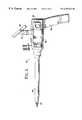
- FIG. 1is a side view in elevation of a penetrating endoscope with a CMOS image sensor and a display.
- FIG. 2is a cross section of the penetrating endoscope of FIG. 1 .
- FIG. 3is a schematic illustration in partial cross section of the penetrating member included in the penetrating endoscope of FIG. 1 .
- FIG. 4is a perspective view of the penetrating endoscope of FIG. 1 .
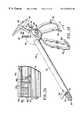
- FIG. 5is a left side view, in elevation, of an alternative embodiment of the penetrating endoscope of the present invention.
- FIG. 6is a schematic illustration in partial cross section of the penetrating member included in the penetrating endoscope of FIG. 5 .
- FIG. 7is a schematic illustration in partial cross section of an alternative embodiment of the penetrating endoscope of the present invention.
- FIG. 8is an enlarged schematic illustration in partial cross section of the distal end of the penetrating endoscope of FIG. 7 .
- FIG. 9is a perspective illustration of the penetrating endoscope of FIG. 1 in use, before penetrating an outer tissue wall.
- FIG. 10is a perspective illustration of the penetrating endoscope of FIG. 9 in use, after penetrating an outer tissue wall.
- FIG. 11is a perspective illustration of the penetrating endoscope of FIG. 9 in use, after removal of the penetrating member.
- FIG. 12is a perspective illustration of the penetrating endoscope of FIG. 5 in use, before penetrating an outer tissue wall.
- FIG. 13is a perspective illustration of the penetrating endoscope of FIG. 12 in use, after penetrating an outer tissue wall.
- FIG. 14is a perspective illustration of the penetrating endoscope of FIG. 12 in use, after removal of the penetrating member.
- FIG. 15is a perspective illustration of the penetrating endoscope of FIGS. 7 and 8 in use, before penetrating an outer tissue wall.
- FIG. 16is a perspective illustration of the penetrating endoscope of FIG. 15 in use, after penetrating an outer tissue wall.
- FIG. 17is a perspective illustration of the penetrating endoscope of FIG. 15 in use, after removal of the penetrating member.
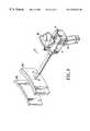
- FIG. 18is a perspective illustration of a surgical instrument including a solid-state endoscope.
- FIG. 19is an enlarged perspective illustration of the distal end of the surgical instrument of FIG. 18 .
- FIG. 20is a partial cross section of the surgical instrument distal end of FIG. 19 showing a cross section of the sealed optics package taken in a plane parallel to the optical axis and perpendicular to the image plane.
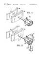
- FIG. 21is a perspective view of an alternative embodiment of the surgical instrument.
- FIG. 22is an enlarged perspective illustration of the proximal end of the surgical instrument of FIG. 21, with the detachable image display.
- FIG. 23is an enlarged perspective illustration of the distal end of the surgical instrument of FIG. 21 .
- FIG. 24is a partial cross section of the endoscope distal end of FIGS. 21 and 23 showing a cross section of the sealed optics package taken in a plane parallel to the optical axis and perpendicular to the image plane.
- FIG. 25is an enlarged perspective illustration of the distal end of the surgical instrument of FIG. 21, with the jaws shown in the open position.
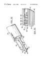
- FIG. 26is a perspective illustration of a surgical instrument including a solid-state endoscope.
- FIG. 27is an enlarged perspective illustration of the distal end left side of the surgical instrument of FIG. 1 .
- FIG. 28is a partial cross section of the surgical instrument distal end of FIG. 27 showing a cross section of the sealed optics package taken in a plane parallel to the optical axis and perpendicular to the image plane.
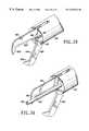
- FIG. 29is an enlarged perspective illustration of the distal end right side of the surgical instrument of FIG. 26 .
- FIG. 30is a perspective view of an alternative embodiment of the surgical instrument having a separate insertable endoscope.
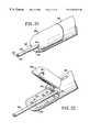
- FIG. 31is an enlarged perspective illustration of the proximal end of the surgical instrument of FIG. 30, with the detachable image display.
- FIG. 32is an enlarged perspective illustration of the distal end of the surgical instrument of FIG. 30 .
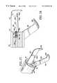
- FIG. 33is a partial cross section of the endoscope distal end of FIGS. 30 and 32 showing a cross section of the sealed optics package taken in a plane parallel to the optical axis and perpendicular to the image plane.
- FIG. 34is an enlarged perspective illustration of the distal end of the surgical instrument of FIGS. 30 and 33, with the cutting end effector jaws shown in the open position.
- a penetrating endoscope 10 according to the present inventionincludes a penetrating member 12 slidably received within a portal sleeve or cannula 14 .
- FIG. 2is a schematic illustration in partial cross section of the penetrating member 12 slidably received within portal sleeve 14 .
- FIG. 3is a schematic illustration in partial cross section illustrating the internal workings of the penetrating member 12 which includes an elongate tube-like body 18 having a proximal end 20 and a sharp penetrating distal end 22 .
- a penetrating member housing 24is carried on the penetrating member elongate body proximal end 20 and includes a housing wall 26 enclosing a housing cavity 28 .
- the penetrating member sharp penetrating distal end 22is substantially transparent and is incorporated in a sealed optics package 32 having a complementary metal oxide semiconductor (CMOS) image sensor 30 disposed along an optical axis 34 with a transparent sharp penetrating tip 46 .
- CMOS image sensor 30includes a CMOS image sensing chip 42 disposed in a plane intersecting and transverse to optical axis 34 .
- CMOS image sensing chip 42is substantially planar and is electrically connected to and carried by a substantially planar printed circuit board 38 having electrical connections 40 for carrying image signals proximally out of the body.
- CMOS image sensing chip 42includes a plurality of picture elements or pixels in a rectangular grid, 640 pixels by 480 pixels.
- CMOS image sensoris meant a solid-state image sensor fabricated using the well known, economical complementary metal oxide semiconductor (CMOS) process, i.e., the integrated circuit (IC) fabrication technology usually combining either or both of enhancement mode N-channel (NMOS) and enhancement mode P-channel (PMOS) field effective transistors (FETs), preferably on a single substrate to form logic gates, memory cells, image sensor pixels, or transistors along with a microprocessor or the like and preferably incorporates, on a single substrate (or chip) image signal processing, memory, and data transmission circuitry to generate image ready signals and transfer the image ready signals out of the body over electrical connection 40 .
- image ready signalis meant a signal processed and adapted to be readily displayed on an image display.
- CMOS image sensing chip 42can be selected to convert periodically sampled individual pixel voltage (or current) levels into a National Television System Committee (NTSC) image signal for transmission out of the body and display on an NTSC compatible image display (e.g., a television).
- NTSCNational Television System Committee
- the CMOS image sensor 30preferably has a plurality of MOS pixel circuits integrated onto chip 42 proximate a Red-Green-Blue (RGB) mosaic color filter panel 44 (as shown in FIG. 3) constituted by a mosaic arrangement of Red-Green-Blue color filters, thus permitting any single pixel to receive either red, green or blue filtered light energy.
- RGBRed-Green-Blue
- the color mosaic filter panel 44is disposed on the optical axis 34 of sealed optics package 32 , ahead of the transverse imaging surface of the CMOS chip 42 .
- the pixels receiving red, green and blue lightgenerate, respectively, red, green and blue pixel light intensity values for color image ready signal generation.
- the objective lens elements 36 comprising the objective lens in sealed optics package 32are preferably fixed in position providing a fixed depth of field at an image plane substantially coplanar or coincident with the plane containing the pixels of CMOS image sensing chip 42 .
- Optical axis 34(shown as a dotted line through sealed optics package 32 in FIG.
- the objective lens comprised of lens elements 36focuses an image corresponding to the endoscope field of view at the image plane intersecting and transverse to the optical axis 34 ; the objective lens is preferably fixed focused, meaning that a fixed depth of field is provided having a selected minimum in focus distance 48 (as shown in FIG. 2 ).
- Transparent penetrating tip 46is therefore disposed at an axial length beyond the image plane containing CMOS image sensing chip 42 ; the axial length 48 is substantially equal to or greater than the minimum in focus distance such that the penetrating member transparent tip 46 is in focus at the image plane containing image sensing tip 42 and the depth of field for sealed optics package 32 renders everything at or beyond transparent tip 46 in focus at the image plane coplanar with CMOS image sensing chip 42 .
- penetrating member 12includes a light source 50 disposed within the penetrating member housing cavity 28 and connected via an optical wave guide 52 for propagating visible light to a distally aimed illumination emitter 54 to illuminate substantially all of the field of view of sealed optics package 32 .
- illumination emitter 54includes a light emitting diode or other light generator energized by conductors carried on the penetrating member elongate body 18 .
- Penetrating member elongate body 18includes, at a medial location, a conforming sliding electrical contact 56 electrically connected to the image sensor printed circuit board electrical connection 40 via one or more electrical conductors carried within the elongate body 18 .
- Sliding electrical contact 56preferably includes a plurality of axially aligned thin strips of conductive material such as gold or copper in a parallel array disposed radially around penetrating member elongate body 18 and carries image ready signal energy proximally, out of the body.
- penetrating member housing 24includes first and second buttons or levers 60 carrying and actuating first and second latches or tab members 62 movably mounted in first and second slots 64 defined in the penetrating member housing wall 26 .
- Each lever 60 and tab member 62is resiliently biased into the outward position (as shown in FIG. 3) by a leaf spring 66 carried on the penetrating member housing wall 26 .
- Penetrating member 12can be used with a conventional trocar cannula such as the Ethicon® ENDOPATH® trocar cannula which includes apertures in the cannula housing for receiving penetrating member tab members 52 .
- An Ethicon trocar having a transparent cannulais disclosed in U.S. Pat. No. 5,256,149 (to Banik et al), the entire disclosure of which is incorporated herein by reference.
- portal sleeve 14is preferably an elongate, rigid, distally tapered tubular, sleeve including a tapered open distal end 72 and a proximal end 70 in communication therewith via an open lumen 74 .
- Portal sleeve 14is generally an elongate tubular member symmetrical about a longitudinal axis and carries, on portal sleeve proximate end 70 , a portal sleeve housing 76 having a portal sleeve housing exterior wall 78 enclosing a portal sleeve housing interior volume 80 .
- Portal sleeve housing interior volume 80includes an inwardly projecting tubular passage 82 terminating distally in a valve seat 84 which can be sealably engaged with a substantially planar flapper valve 86 carried by and pivoting about a flapper valve pivot pin 88 .
- Flapper valve 86is spring biased toward tubular passage valve seat 84 by a resilient leaf spring member 90 .
- Flapper valve 86includes, preferably, a plurality of electrical contacts 100 aligned in a parallel array on flapper valve distal end 112 for cooperative sliding engagement with the penetrating member sliding electrical contacts 56 arrayed on the penetrating member elongate body 18 when the penetrating member is received within the portal sleeve, as shown in FIG. 2 .
- Flapper valve contacts 100are preferably connected to one ore more electrical conductors 114 for transmitting or carrying the image signal.
- a hollow portal sleeve housing handle 118projects transversely from and is carried by the portal sleeve housing 76 and includes a rectangular access opening 119 a that receives handle access cover 120 .
- Access cover 120is detachably attached to portal sleeve housing handle 118 and is retained in place by first and second projecting resilient tabs 121 which are received within the hollow portal sleeve housing handle interior and snap-fit into cooperating notches 123 in the housing side wall 122 interior surfaces.
- the hollow portal sleeve handle interior volumereceives a removable (and preferably disposable) power cell or battery 124 having first and second electrical contacts; battery 124 provides power for energizing all of the electrical and electronics circuitry in penetrating endoscope 10 .
- a voltage supply busis provided using electrical conductors within portal sleeve housing handle 118 and portal sleeve housing 76 for providing electrical energy to the CMOS image sensor 30 , the data transmission circuits and the solid state display 128 .
- Display 128is a substantially planar solid state video monitor receiving image ready signals from CMOS image sensor 30 and providing a readily visible display of objects in the field of view of the image sensor.
- Display 128is carried atop an adjustable or repositionable mount or stalk 130 affixed upon portal sleeve housing 76 .
- Adjustable mount 130has first and second position adjustment control knobs (as best seen in FIG. 1) for adjusting the angular orientation of display 128 , thereby permitting the surgeon to aim the display for convenient observation.
- Display 128is preferably implemented as a Liquid crystal display, a CMOS solid state display, a flat-panel plasma display or any other compact, relatively high definition type of display and is preferably detachably mounted and includes detachable electrical connectors for convenient removal and reattachment, thereby permitting the portal sleeve housing to be discarded after use.
- an alternative embodimentincludes a penetrating endoscope 150 having a display mounted on the penetrating member housing instead of the portal sleeve housing.
- penetrating endoscope 150includes a penetrating member 152 and portal sleeve 154 .
- Penetrating member 152includes a penetrating member elongate body 158 having a sharp distal end 162 opposite a proximal end 160 .
- Proximal end 160carries a penetrating member housing 164 which includes a transversely projecting penetrating member housing handle 166 and an adjustably mounted penetrating housing display 168 affixed atop an adjustable display mount 170 .
- Penetrating member 152includes a CMOS image sensor 172 incorporated into a sealed optics package 174 having a transparent penetrating distal tip.
- An electrical connection 176preferably including a plurality of conductors connects CMOS image sensor 172 with display 168 ; electrical connection 176 terminates distally at the CMOS image sensor printed circuit board and is preferably contained within the interior of penetrating member elongate body 158 and terminates proximally within penetrating member housing 164 in a connection to display 168 thereby transmitting image signal energy proximally and out of the body to the display.
- Penetrating member 152also includes a light source 178 preferably contained within penetrating member housing 164 and generating light to be transmitted distally over optical wave guide 180 to an illumination emitter 182 .
- Illumination emitter 182is advantageously contained within a sidewall of sealed optics package 174 and projects a distal beam of illumination which is at least coextensive with the field of view of CMOS image sensor 172 .
- Portal sleeve 154is terminated proximally at a portal sleeve housing 186 which retains penetrating member housing 164 by operation of the biased tab numbers 188 , as above.
- Penetrating endoscope 150 of FIGS. 5 and 6may be grasped by handle 166 and after the penetrating step, may be separated by actuation of bias tab members 188 thereby allowing the surgeon to withdraw the entire penetrating member 152 from portal sleeve 154 thereby removing the CMOS image sensor 172 and display 168 , both of which are carried by the removable penetrating member 152 .
- FIG. 7Yet another embodiment of the penetrating endoscope of the present invention is illustrated in FIG. 7 and includes first and second CMOS image sensors.
- a first CMOS image sensoris incorporated in the penetrating distal tip of the penetrating member and a second CMOS image sensor is incorporated into the portal sleeve in close proximity to the tapered open end.
- FIG. 8shows the distal ends of penetrating member 210 and the portal sleeve 212 .
- penetrating endoscope 200has a configuration very similar to that discussed above and includes a penetrating member 210 disposed within a portal sleeve 212 where the penetrating member includes an elongate body 214 having a proximal end 216 opposite a sharp distal end 218 .
- a penetrating member housing 220is carried on the proximal end of elongate body 214 .
- CMOS image sensor 224disposed within the penetrating member sharp distal end 218 as well as a second portal sleeve mounted CMOS image sensor 238 disposed near the open distal end of portal sleeve 212 (and as best seen in the enlarged view of the instrument distal end shown in FIG.
- Penetrating member CMOS image sensor 222is enclosed within a sealed optics package 224 and is connected with a penetrating member image sensor electrical connection 226 including a plurality of electrical conductors trained distally within penetrating member elongate body 214 to a sliding contact 227 adapted to make a sliding electrical connection with a flapper valve sliding contact 229 for transmitting image signals from the penetrating member image sensor 222 proximally for display.
- a penetrating member light source 228is disposed within penetrating member housing 220 and generates light or illumination conducted distally over a penetrating member optical wave guide 230 for transmitting illumination distally to the penetrating member illumination emitter 232 best seen in FIG. 8 .
- Portal sleeve 212is terminated proximally in the hollow portal sleeve housing 236 upon which is mounted an adjustable display similar to that shown in FIGS. 1 and 4.
- Portal sleeve housing 236also includes an image signal control module (not shown) responsive to the presence of penetrating member 210 for controlling the selection of which image signal to display, that from penetrating member CMOS image sensor 222 or, alternatively, from that portal sleeve CMOS image sensor 238 .
- the image signal control modulemay be adjusted to display images from both image sensors on the portal sleeve housing display.
- Portal sleeve CMOS image sensor 238is preferably reduced in size as compared to the penetrating member image sensor 222 and readily fits in a transversely projecting blister, thereby permitting visualization from the portal sleeve without substantially reducing the ease of insertion of the penetrating endoscope 200 .
- Portal sleeve image sensor 238is integrated into a sealed optics package 240 and is connection via an electrical connection 242 running proximally into portal sleeve housing 236 via wires embedded in the portal sleeve sidewall 243 .
- a portal sleeve light source 244is disposed within portal sleeve housing 236 and light generated in light source 244 is propagated distally via optical wave guides 246 to a portal sleeve illumination emitter 248 , best seen in the enlarged view of FIG. 8, and illuminates substantially all of the field of view of portal sleeve CMOS image sensor 238 .
- the penetrating endoscope of the present inventionprovides the surgeon with a view of tissue or organ structures during the penetrating steps and, optionally, a view of organ structures and foreign objects inside the body after penetration.
- penetrating endoscope 10is shown penetrating an outer tissue wall 260 to provide visualization of an interior organ wall 262 bearing a plurality of interior organ wall surface features 264 .
- penetrating endoscope 10is positioned against outer tissue wall 260 and sharp penetrating distal end 22 is positioned at the desired puncture site.
- Display 128shows the image observed via CMOS image sensor during the puncturing step. As shown in FIG.
- the surgeonapplies a forward thrusting force to penetrating endoscope 10 using transverse projecting handle 118 thereby puncturing or penetrating through outer tissue wall 260 into the cavity between outer tissue wall 260 and interior organ wall 262 ; sharp penetrating distal end 22 is disposed in a space between outer tissue wall 260 and interior organ wall 262 thereby permitting the surgeon to view the interior organ wall surface features 264 as perceived from the point of view of the CMOS image sensor 30 disposed within penetrating member distal end 22 .
- Display 128shows surface features 264 , permitting the surgeon to identify interior organ wall 262 by recognition of surface features 264 .
- the surgeonremoves penetrating member 12 from portal sleeve 14 thereby removing CMOS image sensor 30 , whereupon display 128 of penetrating endoscope 10 conveys no further information to the surgeon.
- the alternative embodiment of the penetrating endoscope 150(of FIG. 5 ), is used as shown in FIGS. 12 , 13 and 14 .
- a surgeonfirst positions penetrating endoscope 150 with sharp distal end 162 (and the included CMOS image sensor 172 ) against an outer tissue wall 260 at the selected penetration site.
- the surgeonapplies a forward thrusting force to penetrating endoscope 150 using transverse projecting handle 166 thereby puncturing or penetrating through outer tissue wall 260 into the cavity between outer tissue wall 260 and interior organ wall 262 whereupon the CMOS image sensor 172 provides a view of interior organ wall surface features 264 on the adjustable display 168 .
- the surgeonmay detach penetrating member housing 164 from portal sleeve housing 154 and remove penetrating member 152 from within the portal sleeve 154 , thereby deactivating display 168 and providing an access port for conventional endoscopic surgery.
- the penetrating member 152 having image sensor 172 and display 168may then be set aside for sterilization, if desired.
- Penetrating endoscope 150optionally combines a reusable, sterilizable penetrating member 152 with a disposable portal sleeve (available from Ethicon Endo-SurgeryTM and others).
- FIGS. 15, 16 and 17the third embodiment of the penetrating endoscope 200 (FIGS. 7 and 8) is illustrated.
- penetrating endoscope 200is positioned against the outer tissue wall 260 in preparation for penetrating through the tissue wall using sharp distal end 218 containing penetrating member CMOS image sensor 220 , the view from which is shown on display 243 .
- the surgeongrasps handle 237 and applies sufficient force to the penetrating endoscope 200 to force the sharp distal end through outer tissue wall 260 while viewing the field of view of the penetrating member image sensor 222 on display 243 .
- display 243receives image signal information from the penetrating member image sensor 222 so long as penetrating member 210 is within portal sleeve 212 .
- the surgeongrasps penetrating member housing 220 and removes penetrating member 210 from portal sleeve 212 , thereby leaving only the portal sleeve image sensor 238 disposed within the body, as shown in FIG. 17 .
- the image control module disposed within portal sleeve housing 236switches the image signal provided to display 243 to show an image corresponding to the image signal generated by portal sleeve image sensor 238 .
- FIG. 16shows the organ wall surface features 264 from perspective of the penetrating member image sensor 222 on display 243 as image 264 a .
- the perspective shown on display 243is shifted slightly and offset as display image 264 b .
- the offset image 264 b generated in the portal sleeve image sensor 238is displaced laterally from the first image 264 a generated by the penetrating member image sensor 222 .
- the surgeoncontinues to view the interior organ wall 262 during any subsequent surgical steps.
- an endoscopic surgical instrument 310can be used to visualize anatomical tissue, organ structures or foreign objects in an anatomical cavity or elsewhere in the body. While the instrument 310 is described hereinafter for use with a tubular portal sleeve (not shown) in endoscopic procedures, such as laparoscopy, the instrument can be used in open surgery or with catheters or other small and large diameter tubular or hollow cylindrical members providing access to small cavities (e.g., veins or arteries) or large cavities (e.g., the abdomen); portal, for purposes of the present invention, is defined as any opening into the body, incised or natural.
- the endoscopic instrumentaccording to a first embodiment of the present invention is illustrated in FIGS. 18 and 19 and includes an elongate cylindrical barrel, or outer shaft 312 with a longitudinal axis and preferably having one or more elongated lumens or passages defined therein (preferably in the form of one or more channels, e.g., 314 ), a barrel distal end 315 for being disposed in the body and a barrel proximal end terminating in and carried by a housing 318 including an exterior wall enclosing an interior volume.
- Housing 318includes scissor type handles 320 and 322 for controlling surgical instruments such as forceps having jaw members 324 , 325 (as best seen in FIG. 19 ), or other end effectors.
- Housing 318also includes a transversely located button 326 for selectively disengaging the scissor type handles 320 and 322 and permitting rotation of the handles about the axis of rotation (as indicated by the arrow A in FIG. 18 ).
- Handles 320 , 322are connected through a linkage mechanism (as is well known in the art) to at least one jaw; in the example of FIG. 18, movable jaw 324 is responsive to the separation between handles 320 , 322 , such that spreading handles 320 , 322 apart opens jaw 324 , separating jaw 324 from fixed jaw 325 .
- Handle rotationallows the surgeon to orient handles 320 and 322 in a desired manner, before or during surgery.
- the handles 320 and 322also include serrated lock protrusions 328 and 330 to interlock and allow the position of handles 320 and 322 to be maintained in a state corresponding to a desired position of the end effectors (e.g., forceps jaws 324 , 325 ).
- Lock protrusions 328 and 330can be pivoted to a position to prevent interlock, if desired.
- Handles 320 and 322are configured to be grasped while the surgeon's fingers pass through the openings in the handles or while the surgeon's fingers are wrapped around the outer portions of the handles, to increase comfort and adaptability.
- the channel 314 in hollow barrel 312is a lumen or passage adapted to receive elongate surgical instruments including a tubular body or member with a proximal end and a distal end being insertable at the proximal end of the barrel channel (e.g., at proximal end 334 ); channel 314 extends through proximal tubular body 335 , which carries a Luer lock 336 and a spherical reservoir 338 for receiving a stop-cock valve 340 , thereby allowing channel 314 to be selectably opened or sealed at the instrument proximal end.
- Housing 318includes a cautery electrode connection 342 for removable electrical connection to a source of electrical energy for cauterizing tissue by passing electrical current through the end effectors (e.g., forceps jaws 324 , 325 as illustrated in FIG. 19 ).
- a substantially planar CMOS image sensor 350includes a plurality of pixels (e.g., in a rectangular grid, 640 pixels by 480 pixels) and is affixed to and carried by instrument barrel distal end 315 .
- the CMOS image sensoris integrated onto a chip 350 e , preferably incorporated into a sealed optics package 350 a including one or more objective lens elements 350 b and a printed circuit board or substrate 350 c carrying electrical connections between electrical conductors or wires 350 d and the CMOS image sensor chip 350 e ; the sealed optics package 350 a is mounted onto or integrated in the distal end 315 of the endoscope shaft 312 , preferably proximate a fiber optic end 352 .
- CMOS image sensoris meant a solid-state image sensor fabricated using the well known, economical, complementary metal oxide semiconductor (CMOS) process, i.e., the Integrated Circuit (IC) fabrication technology usually combining either or both of enhancement mode N-channel (NMOS) and enhancement mode P-channel (PMOS) Field Effect Transistors (FETs), preferably on a single substrate to form logic gates, memory cells, or image sensor pixels.
- CMOS image sensorsare fabricated using the CMOS process and preferably incorporate, on a single substrate (or chip), image signal processing, memory, and data transmission circuitry to generate image ready signals and transfer the image ready signals out of the body.
- image ready signalis meant a signal processed and adapted to be readily displayed on an image display.
- signal processing circuits on chip 350 ecan convert periodically sampled individual pixel voltage (or current) levels into a National Television System Committee (NTSC) image signal for transmission out of the body and display on an NTSC compatible image display (e.g., television).
- NTSCNational Television System Committee
- the CMOS image sensor 350preferably has a plurality of MOS pixel circuits integrated onto chip 350 e proximate a Red-Green-Blue (RGB) mosaic color filter panel 350 f (as shown in FIG. 20) constituted by a mosaic arrangement of red, green, and blue color filters (or optionally, cyan, magenta and yellow color filters), thus permitting any single pixel to receive either red, green or blue (or cyan, magenta and yellow) filtered light energy.
- the color mosaic filter panel 350 fis disposed on the optical axis of optics package 350 a , ahead of the transverse imaging surface of the CMOS chip 350 e .
- the pixels receiving red, green, and blue lightgenerate, respectively, red, green, and blue pixel light intensity values, for color image ready signal generation.
- the lens elements 350 b comprising the objective lens in sealed optics package 350 aare preferably fixed in position providing a fixed depth of field at an image plane substantially coincident with a plane containing the pixels of CMOS image sensing chip 350 e .
- the optical axis 350 i(shown as a dotted line through sealed optics package 350 a in FIG. 20) extends linearly from the image light transmissive, sealed protective cover or window 350 h mounted on barrel distal end 315 , proximally to image sensing chip 350 e being disposed transverse thereto, in the image plane.
- the objective lens comprised of lens elements 350 bfocuses an image corresponding to the endoscope field of view at the image plane intersecting and transverse to the optical axis 350 i .
- the objective lensis preferably fixed focus, meaning that a fixed depth of field is provided having a selected minimum in-focus distance 350 g.
- the objective lens elements 350 b in sealed optics package 350 aare selected and positioned to define a focal plane coincident with the image plane of image sensor chip 350 e .
- the objective lens elements 350 bmay be individually movable using a motorized focus control mechanism and may also provide variable magnification (i.e., zoom), as is known in the art.
- the lens elementsare fixed in position to provide an in-focus image at all distances from the barrel distal end 315 greater than selected minimum in-focus distance 350 g .
- Fixed focus opticsare preferred for disposable embodiments. As shown in FIG.
- the fixed focus optics of the sealed optics package 350 aprovide a minimum focus distance 350 g (i.e., a minimum distance from the objective lens elements for which an observed object will remain in focus) less than or equal to the length of the forceps jaw 325 (or the length of any other surgical instrument end effector), thus ensuring that the surgeon can see a focused image of objects just within the grasp of the end effector, and beyond.
- a minimum focus distance 350 gi.e., a minimum distance from the objective lens elements for which an observed object will remain in focus
- the length of the forceps jaw 325or the length of any other surgical instrument end effector
- surgical instrument 310preferably includes a distally mounted adjustable image display 390 carried on housing 318 .
- Display 390can be a Liquid Crystal Display (LCD), a flat panel plasma display or a High Intensity Discharge (HID) display, mounted on a flexible stalk 392 for convenient repositioning during a surgical procedure.
- the displayis preferably release-ably connect-able using a locking electrical connector 396 , thereby permitting removal of display 390 before sterilizing or discarding endoscopic instrument 310 , after use.
- a proximal light sourceis carried within the interior volume of housing 318 and is selectively energized to provide illumination transmitted distally through a fiber optic waveguide within barrel 312 and radiated distally from fiber optic distal end 352 .
- Light radiating distally from fiber optic end 352illuminates substantially all of the field of view of CMOS image sensor 350 and can be turned on or off by operation of a micro-switch (not shown) carried on housing 318 .
- the light sourceis powered electrically through a housing cable proximally terminated in an electrical connector, or via a battery preferably carried within housing 318 .
- a surgical instrument 356has a housing carrying an elongate hollow barrel including a lumen or channel 358 with an elongate endoscope 360 extending through at least a portion of barrel channel 358 .
- Elongate tubular endoscope 360includes a cylindrical member, body or barrel 362 having a distal end 64 adapted to be slidably received within instrument channel 358 and opposite a proximal endoscope housing 366 carried upon endoscope proximal end 368 .
- a light sourceis contained within housing 366 and provides light transmitted distally through a fiber optic bundle 370 terminating distally in fiber optic end 372 .
- a CMOS image sensor 350is affixed to and carried by distal end 364 of the elongate member or body 362 of tubular endoscope 360 and provides a distally aimed endoscope field of view.
- Light radiating distally from fiber optic end 372illuminates substantially all of the field of view of CMOS image sensor 350 and is turned on or off by operation of a micro-switch (not shown) carried on housing 366 .
- the light sourceis powered electrically through a housing cable 376 proximally terminated in an electrical connector 378 (as shown in FIG. 22 ).
- CMOS image sensor 350preferably includes a rectangular array (e.g., 640 ⁇ 480) of MOS pixel circuits integrated onto chip 350 e proximate a Red-Green-Blue (RGB) mosaic color filter panel 350 f (as shown in FIG. 24) constituted by a mosaic arrangement of red, green, and blue color filters (or, as above, cyan, magenta and yellow color filters), thus permitting any single pixel to receive either red, green or blue (or cyan, magenta and yellow) filtered light energy.
- the color mosaic filter panel 350 fis disposed on the optical axis of optics package 350 a , ahead of the transverse imaging surface of the CMOS chip 350 e .
- the pixels receiving red, green, and blue lightgenerate, respectively, red, green, and blue pixel light intensity values, for color image signal generation.
- the lens elements 350 b comprising the objective lens in sealed optics package 350 aare preferably fixed in position providing a fixed depth of field at an image plane substantially coincident with a plane containing the pixels of CMOS image sensing chip 350 e .
- the optical axis 350 i(shown as a dotted line through sealed optics package 350 a in FIG. 24) extends linearly from the image light transmissive, sealed protective cover or window 350 h mounted on member distal end 364 , proximally to image sensing chip 350 e being disposed transverse thereto, in the image plane.
- the objective lens comprised of lens elements 350 bfocus an image corresponding to the endoscope field of view at the image plane intersecting and transverse to the optical axis 350 i .
- the objective lensis fixed focus, meaning that a fixed depth of field is provided having a selected minimum in-focus distance (e.g., one centimeter).
- the objective lens elements 350 b in sealed optics package 350 aare selected and positioned to provide a focal plane coincident with the image plane of image sensor chip 350 e .
- the objective lens elements 350 bmay be individually movable using a motorized focus control mechanism and may also provide variable magnification (i.e., zoom), as is known in the art.
- the lens elementsare fixed in position to provide an in-focus image at all distances from the endoscope distal end 364 greater than the selected minimum in-focus distance. As shown in FIG.
- the fixed focus optics of the sealed optics package 350 aprovide a minimum focus distance (i.e., a minimum distance from the objective lens window 350 h or member distal end 364 for which an observed object will remain in focus) less or equal to the length of fixed forceps jaw 325 (or the length of any other surgical instrument end effector), thus ensuring that the surgeon can see a focused image of objects just within the grasp of the end effector, and beyond, when the endoscope 360 is slidably positioned within channel 358 with endoscope distal end 364 aligned with (i.e., even with and not projecting beyond) barrel distal end 315 a .
- a minimum focus distancei.e., a minimum distance from the objective lens window 350 h or member distal end 364 for which an observed object will remain in focus
- the length of fixed forceps jaw 325or the length of any other surgical instrument end effector
- endoscope 360may be translated distally to project well beyond the barrel distal end 315 a (as shown in FIG. 25) in which case objects beyond the minimum in-focus distance (and further) will be in focus at the image plane coincident with CMOS image sensor chip 350 e .
- the semiconductor chip 350 eincludes a CMOS imaging sensor and, preferably, a microprocessor and a signal processing circuit for generating image ready signals for transmission to a display and to a data logging computer, outside the body.
- Image signal datais transmitted proximally from CMOS image sensor 350 , preferably via an image signal cable 380 running just within the exterior surface of barrel 362 .
- image ready datais transmitted proximally and out of the body to a movably adjustable, release-ably connect-able display 390 and/or to an image data logging recorder or computer (not shown) through an image data cable electrically connected with image signal cable 380 .
- endoscope 360may be advanced distally through channel 314 , up to and beyond the distal end 382 of forceps jaws 324 a , 325 .
- at least one jaw 324 a(or other end effector) includes a groove 384 to permit endoscope 360 (or another surgical instrument) to pass therethrough when the jaws are closed (as shown in FIG. 23 ).
- surgical instrument 356preferably includes proximally mounted adjustable image display 390 carried on a flexible stalk 392 for convenient repositioning during a surgical procedure and preferably release-ably connect-able using a locking electrical connector 396 , thereby permitting removal of display 390 before sterilizing or discarding endoscopic instrument 356 after use.
- the endoscopic instruments of the present inventionmay be aimed to provide the desired field of view of a procedure and may include a sealed optics package in the form of an articulable ball joint having the CMOS imaging sensor and a light source for illuminating the field of visualization; the ball joint imaging sensor aim is preferably articulable or controllable from the instrument proximal end using wire control members connected to housing mounted control wheels.
- the endoscopehas a fixed objective lens carried on the distal end of a tubular body and a lens train or fiberoptic bundle transmits the endoscopic image proximally to a CMOS image sensor located in a housing (e.g., 318 or 366 ).
- a CMOS image sensorlocated in a housing (e.g., 318 or 366 ).
- an endoscopic surgical instrument 410can be used to visualize anatomical tissue, organ structures or foreign objects in an anatomical cavity or elsewhere in the body. While the instrument 410 is described hereinafter for use with a tubular portal sleeve (not shown) in endoscopic procedures, such as laparoscopy, the instrument can be used in open surgery or with catheters or other small and large diameter tubular or hollow cylindrical members providing access to small cavities (e.g., veins or arteries) or large cavities (e.g., the abdomen); portal, for purposes of the present invention, is defined as any opening into the body, incised or natural.
- the endoscopic instrumentaccording to another alternative embodiment of the present invention is illustrated in FIGS. 26, 27 , 28 and 29 and includes an elongate cylindrical barrel, or other shaft 412 with a longitudinal axis and preferably having one or more elongated lumens or passages defined therein (preferably in the form of one or more channels, e.g., 414 ), a barrel distal end 415 for being disposed in the body and a barrel proximal end terminating in and carried by a housing 418 including an exterior wall enclosing an interior volume.
- Housing 418includes scissor type handles 420 and 422 for controlling surgical instruments such as a cutting end effector having cutting jaw members 424 , 425 (as best seen in FIG. 27 ), or other end effectors.
- Housing 418also includes a transversely located button 426 for selectively disengaging the scissor type handles 420 and 422 and permitting rotation of the handles about the axis of rotation (as indicated by the arrow A′ in FIG. 26 ).
- Handles 420 , 422are connected through a linkage mechanism (as is well known in the art) to at least one jaw; in the example of FIG. 26, movable jaw 424 is responsive to the separation between handles 420 , 422 , such that spreading handles 420 , 422 apart opens jaw 424 , separating jaw 424 from fixed jaw 425 .
- jaws 424 and 425are hingedly carried by barrel 412 adjacent the barrel distal end 415 .
- the jawsare shown in a fully open position in FIGS. 27 and 28 and are closed in a continuous movement to assume the closed position illustrated in FIGS. 30 and 32.
- Upper cutting jaw 425includes a substantially planar blade member substantially aligned with the central axis of barrel 412 and includes a cutting edge 425 a having a selected edge length and terminated distally in a tapered transverse barb 425 b ; similarly, lower, movable cutting jaw 424 includes a substantially planar blade member substantially aligned with the central axis of barrel 412 and includes a cutting edge 424 a having a selected edge length and terminated distally in a tapered transverse barb 424 b .
- transverse barbs 424 b , 425 boverlap, as shown in FIG. 32 .
- Handle rotationallows the surgeon to orient handles 420 and 422 in a desired manner, before or during surgery.
- the handles 420 and 422also include serrated lock protrusions 428 and 430 to interlock and allow the position of handles 420 and 422 to be maintained in a state corresponding to a desired position of the end effector jaws 424 , 425 .
- Lock protrusions 428 and 430can be pivoted to a position to prevent interlock, if desired.
- Handles 420 and 422are configured to be grasped while the surgeon's fingers pass through the openings in the handles or while the surgeon's fingers are wrapped around the outer portions of the handles, to increase comfort and adaptability.
- the channel 414 in hollow barrel 412is a lumen or passage adapted to receive elongate surgical instruments including a tubular body or member with a proximal end and a distal end being insertable at the proximal end of the barrel channel (e.g., at proximal end 434 ); channel 414 extends through proximal tubular body 435 , which carries a Luer lock 436 and a spherical reservoir 438 for receiving a stop-cock valve 440 , thereby allowing channel 414 to be selectably opened or sealed at the instrument proximal end.
- Housing 418includes a cautery electrode connection 442 for removable electrical connection to a source of electrical energy for cauterizing tissue by passing electrical current through the end effector jaws 424 , 425 , as illustrated in FIG. 26 .
- a substantially planar CMOS image sensor 450includes a plurality of pixels (e.g., in a rectangular grid, 640 pixels by 480 pixels) and is affixed to and carried by instrument barrel distal end 415 .
- the CMOS image sensoris integrated onto a chip 450 e , preferably incorporated into a sealed optics package 450 a including one or more objective lens elements 450 b and a printed circuit board or substrate 450 c carrying electrical connections from connecting wires 450 d to the CMOS image sensor chip 450 e ; the sealed optics package 450 a is mounted onto or integrated in the distal end 415 of the endoscope shaft 412 , preferably proximate a fiber optic end 452 (as best seen in FIG. 29 ).
- signal processing circuits on chip 450 ecan convert periodically sampled individual pixel voltage (or current) levels into a National Television System Committee (NTSC) image signal for transmission out of the body and display on an NTSC compatible image display (e.g., a television).
- NTSCNational Television System Committee
- the CMOS image sensor 450preferably has a plurality of MOS pixel circuits integrated onto chip 450 e proximate a Red-Green-Blue (RGB) mosaic color filter panel 450 f (as shown in FIG. 28) constituted by a mosaic arrangement of red, green, and blue color filters (or optionally, cyan, magenta and yellow color filters), thus permitting any single pixel to receive either red, green or blue (or cyan, magenta and yellow) filtered light energy.
- the color mosaic filter panel 450 fis disposed on the optical axis of optics package 450 a , ahead of the transverse imaging surface of the CMOS chip 450 e .
- the pixels receiving red, green, and blue lightgenerate, respectively, red, green, and blue pixel light intensity values, for color image ready signal generation.
- the lens elements 450 bcomprising the objective.
- lens in sealed optics package 450 aare preferably fixed in position providing a fixed depth of field at an image plane substantially coincident with a plane containing the pixels of CMOS image sensing chip 450 e .
- the optical axis 450 i(shown as a dotted line through sealed optics package 450 a in FIG.
- the objective lenscomprised of lens elements 450 b focuses an image corresponding to the endoscope field of view at the image plane intersecting and transverse to the optical axis 450 i .
- the objective lensis preferably fixed focus, meaning that a fixed depth of field is provided having a selected minimum in-focus distance 450 g.
- the objective lens elements 450 b in sealed optics package 450 aare selected and positioned to define a focal plane coincident with the image plane of image sensor chip 450 e .
- the objective lens elements 450 bmay be individually movable using a motorized focus control mechanism and may also provide variable magnification (i.e., zoom), as is known in the art.
- the lens elementsare fixed in position to provide an in-focus image at all distances from the barrel distal 415 greater than selected minimum in-focus distance 450 g .
- Fixed focus opticsare preferred for disposable embodiments. As shown in FIG.
- the fixed focus optics of the sealed optics package 450 aprovide a minimum focus distance 450 g (i.e., a minimum distance from the objective lens elements for which an observed object will remain in focus) less than or equal to the length of the edge 425 a of cutting jaw 425 (or the length of any other surgical instrument and effector), thus ensuring that the surgeon can see a focused image of objects just within the grasp of the end effector (e.g., within the grasp of the transverse barbs 424 b , 425 b ), and beyond.
- a minimum focus distance 450 gi.e., a minimum distance from the objective lens elements for which an observed object will remain in focus
- the length of the edge 425 a of cutting jaw 425or the length of any other surgical instrument and effector
- surgical instrument 410preferably includes a distally mounted adjustable image display 490 carried on housing 418 .
- Display 490can be a Liquid Crystal Display (LCD), a flat panel plasma display, a High Intensity Discharge (HID) display or a solid state display (e.g., including a CMOS display panel), mounted on a flexible stalk 492 for convenient repositioning during a surgical procedure.
- the displayis preferably release-ably connect-able using a locking electrical connector 496 , thereby permitting removal of display 490 before sterilizing or discarding endoscopic instrument 410 , after use.
- a proximal light sourceis carried within the interior volume of housing 418 and is selectively energized to provide illumination transmitted distally through a fiber optic waveguide within barrel 412 and radiated distally from fiber optic distal end 452 .
- Light radiating distally from fiber optic end 452illuminates substantially all of the field of view of CMOS image sensor 450 and can be turned on or off by operation of a micro-switch (not shown) carried on housing 418 .
- the light sourceis powered electrically through a housing cable proximally terminated in an electrical connector, or via a battery preferably carried within housing 418 .
- a surgical instrument 456has a housing carrying an elongate hollow barrel 457 including a lumen or channel 458 with an elongate tubular endoscope 460 extending through at least a portion of barrel channel 458 .
- Elongate tubular endoscope 460includes a cylindrical member or body 462 having distal end 464 (adapted ro be slidably received within instrument channel 458 ) opposing a proximal endoscope housing 466 carried upon endoscope proximal end 468 .
- a light sourceis contained within housing 466 and provides light transmitted distally through a fiber optic bundle 470 terminating distally in fiber optic end 472 .
- a CMOS image sensor 450is affixed to and carried by distal end 464 of the elongate member or body 462 of tubular endoscope 460 and provides a distally aimed endoscope field of view.
- Light radiating distally from fiber optic end 472illuminates substantially all of the field of view of CMOS image sensor 450 and is turned on or off by operation of a micro-switch (not shown) carried on housing 466 .
- the light sourceis powered electrically through a housing cable 476 proximally terminated in an electrical connector 478 (as shown in FIG. 30 ).
- CMOS image sensor 450preferably includes a rectangular array (e.g., 640 ⁇ 480) of MOS pixel circuits integrated onto chip 450 e proximate a Red-Green-Blue (RGB) mosaic color filter panel 450 f (as shown in FIG. 32) constituted by a mosaic arrangement of red, green, and blue color filters (or, as above, cyan, magenta and yellow color filters), thus permitting any single pixel to receive either red, green or blue (or cyan, magenta and yellow) filtered light energy.
- the color mosaic filter panel 450 fis disposed on the optical axis of optics package 450 a , ahead of the transverse imaging surface of the CMOS chip 450 e .
- the pixels receiving red, green, and blue lightgenerate, respectively, red, green, and blue pixel light intensity values, for color image signal generation.
- the lens elements 450 b comprising the objective lens in sealed optics package 450 aare preferably fixed in position providing a fixed depth of field at an image plane substantially coincident with a plane containing the pixels of CMOS image sensing chip 450 e .
- the optical axis 450 i(shown as a dotted line through sealed optics package 450 a in FIG. 33) extends linearly from the image light transmissive, sealed protective cover or window 450 h mounted on member distal end 464 , adjacent to image sensing chip 450 e being disposed transverse thereto, in the image plane.
- the objective lenscomprised of lens elements 450 b focus an image corresponding to the endoscope field of view at the image plane intersecting and transverse to the optical axis 450 i .
- the objective lensis fixed focus, meaning that a fixed depth of field is provided having a selected minimum in-focus distance (e.g., one centimeter).
- the objective lens elements 450 b in sealed optics package 450 aare selected and positioned to provide a focal plane coincident with the image plane of image sensor chip 450 e .
- the objective lens elements 450 bmay be individually movable using a motorized focus control mechanism and may also provide variable magnification (i.e., zoom), as is known in the art.
- the lens elementsare fixed in position to provide an in-focus image at all distances from the body distal end 464 greater than the selected minimum in-focus distance. As shown in FIG.
- the fixed focus optics of the sealed optics package 450 aprovide a minimum focus distance (i.e., a minimum distance from the objective lens window 450 h mounted on or adjacent to member distal end 464 for which an observed object will remain in focus) less than or equal to the length of fixed cutting jaw 425 (or the length of any other surgical instrument end effector), thus ensuring that the surgeon can see a focused image of objects just within the grasp of the end effector, and beyond, when the endoscope 460 is slidably positioned within channel 458 with endoscope distal end 464 aligned with (i.e., even with and not projecting beyond) barrel distal end 415 a .
- a minimum focus distancei.e., a minimum distance from the objective lens window 450 h mounted on or adjacent to member distal end 464 for which an observed object will remain in focus
- the length of fixed cutting jaw 425or the length of any other surgical instrument end effector
- endoscope 460may be translated distally to project well beyond the barrel distal end 415 a (as shown in FIGS. 7 and 9) in which case objects beyond the minimum in-focus distance (and further) will be in focus at the image plane coincident with CMOS image sensor chip 450 e.
- Semiconductor chip 450 eincludes a CMOS imaging sensor and, preferably, a microprocessor and a signal processing circuit for generating image ready signals for transmission to a display and to a data logging computer, outside the body.
- Image signal datais transmitted proximally from CMOS image sensor 450 , preferably via an image signal cable 480 running just within the exterior surface of barrel 462 .
- image ready datais transmitted proximally and out of the body to a movably adjustable, release-ably connect-able display 490 and/or to an image data logging recorder or computer (not shown) through an image data cable electrically connected with image signal cable 480 .
- endoscope 460may be advanced distally through channel 458 , up to and beyond the distal end 482 of cutting jaws 424 , 425 , which are laterally offset therefrom.
- surgical instrument 456preferably includes proximally mounted adjustable image display 490 carried on a flexible stalk 492 for convenient repositioning during a surgical procedure and preferably release-ably connect-able using a locking electrical connector 496 , thereby permitting removal of display 490 before sterilizing or discarding endoscopic instrument 456 after use.
- the endoscopic instruments of the present inventionmay be aimed to provide the desired field of view of a procedure and may include a sealed optics package in the form of an articulable ball joint having the CMOS imaging sensor and a light source for illuminating the field of visualization; the ball joint imaging sensor aim is preferably articulable or controllable from the instrument proximal end using wire control members connected to housing mounted control wheels.
- the endoscopehas a fixed objective lens carried on the distal end of a tubular body and a lens train or fiberoptic bundle transmits the endoscopic image proximally to a CMOS image sensor located in a housing (e.g., 418 or 466 ).
- a CMOS image sensorlocated in a housing (e.g., 418 or 466 ).
- CMOS image sensorincludes all solid state integrated circuits fabricated by the well known CMOS process producing chips having a plurality of pixels for converting image light energy into electrical image signal energy.
- the CMOS image sensor of the present inventionincludes, on the same chip or integrated circuit, an image processing circuit for converting periodically sampled pixel voltage (or current) levels into an image ready signal adapted for transmission out of the body (e.g., by electric signal conduction through wires or by transmission through an RF, microwave, ultrasonic, acoustic or fiber-optic data channel).
- An image ready signalmeans a signal processed and formatted (or otherwise adapted) for display on an image display or monitor.
- a CMOS image sensor pixelas used herein, means a CMOS image sensor picture element, usually occupying a defined region in a two dimensional array, for gathering light in the defined region.
- a red pixel, a green pixel, and a blue pixeloccupy three sub-regions within a color pixel region and red, green and blue color optical filters are incorporated into a color mosaic filter element and disposed adjacent to the respective CMOS image sensor pixel subregions.
- Depth of fielddescribes the range of distances from the image sensor for which an object within the field of view will be in focus and resolved in sharp detail.
Landscapes
- Health & Medical Sciences (AREA)
- Life Sciences & Earth Sciences (AREA)
- Surgery (AREA)
- Engineering & Computer Science (AREA)
- Molecular Biology (AREA)
- Heart & Thoracic Surgery (AREA)
- Veterinary Medicine (AREA)
- Nuclear Medicine, Radiotherapy & Molecular Imaging (AREA)
- Public Health (AREA)
- Pathology (AREA)
- General Health & Medical Sciences (AREA)
- Animal Behavior & Ethology (AREA)
- Biomedical Technology (AREA)
- Medical Informatics (AREA)
- Physics & Mathematics (AREA)
- Radiology & Medical Imaging (AREA)
- Optics & Photonics (AREA)
- Biophysics (AREA)
- Multimedia (AREA)
- Signal Processing (AREA)
- Endoscopes (AREA)
- Instruments For Viewing The Inside Of Hollow Bodies (AREA)
Abstract
Description
Claims (88)
Priority Applications (1)
| Application Number | Priority Date | Filing Date | Title |
|---|---|---|---|
| US09/310,112US6387043B1 (en) | 1998-05-13 | 1999-05-12 | Penetrating endoscope and endoscopic surgical instrument with CMOS image sensor and display |
Applications Claiming Priority (4)
| Application Number | Priority Date | Filing Date | Title |
|---|---|---|---|
| US8524398P | 1998-05-13 | 1998-05-13 | |
| US8524298P | 1998-05-13 | 1998-05-13 | |
| US9306998P | 1998-07-16 | 1998-07-16 | |
| US09/310,112US6387043B1 (en) | 1998-05-13 | 1999-05-12 | Penetrating endoscope and endoscopic surgical instrument with CMOS image sensor and display |
Publications (1)
| Publication Number | Publication Date |
|---|---|
| US6387043B1true US6387043B1 (en) | 2002-05-14 |
Family
ID=27375032
Family Applications (1)
| Application Number | Title | Priority Date | Filing Date |
|---|---|---|---|
| US09/310,112Expired - Fee RelatedUS6387043B1 (en) | 1998-05-13 | 1999-05-12 | Penetrating endoscope and endoscopic surgical instrument with CMOS image sensor and display |
Country Status (6)
| Country | Link |
|---|---|
| US (1) | US6387043B1 (en) |
| EP (1) | EP1079724A1 (en) |
| JP (1) | JP2002514448A (en) |
| AU (1) | AU3893299A (en) |
| CA (1) | CA2332107A1 (en) |
| WO (1) | WO1999058044A1 (en) |
Cited By (160)
| Publication number | Priority date | Publication date | Assignee | Title |
|---|---|---|---|---|
| US20020165444A1 (en)* | 2001-04-20 | 2002-11-07 | Whitman Michael P. | Imaging device |
| US20030013936A1 (en)* | 2001-07-11 | 2003-01-16 | Jackson Avery M. | Endoscopic pedicle probe |
| US20030032861A1 (en)* | 1998-06-22 | 2003-02-13 | Lunsford John P. | Combined vessel dissection and transection device and method |
| US20030163029A1 (en)* | 2000-09-21 | 2003-08-28 | Elazar Sonnenschein | Multiple view endoscopes |
| EP1374793A1 (en)* | 2002-06-17 | 2004-01-02 | Biosense, Inc. | Invasive medical device with position sensing and display |
| US20040186368A1 (en)* | 2003-03-21 | 2004-09-23 | Scimed Life Systems, Inc. | Systems and methods for internal tissue penetration |
| US20050020909A1 (en)* | 2003-07-10 | 2005-01-27 | Moctezuma De La Barrera Jose Luis | Display device for surgery and method for using the same |
| US20050234347A1 (en)* | 2004-03-29 | 2005-10-20 | Fujinon Corporation | Puncture-type endoscopic probe |
| US20050288622A1 (en)* | 2004-06-29 | 2005-12-29 | Applied Medical Resources Corporation | Insufflating optical surgical instrument |
| US20060149129A1 (en)* | 2005-01-05 | 2006-07-06 | Watts H D | Catheter with multiple visual elements |
| US20060206118A1 (en)* | 2005-03-11 | 2006-09-14 | Kim Daniel H | Percutaneous endoscopic access tools for the spinal epidural space and related methods of treatment |
| US20070030344A1 (en)* | 2004-04-12 | 2007-02-08 | Olympus Corporation | Endoscope device |
| US20070177009A1 (en)* | 2005-01-05 | 2007-08-02 | Avantis Medical Systems, Inc. | Endoscope assembly with a polarizing filter |
| US20070188604A1 (en)* | 2004-02-16 | 2007-08-16 | Olympus Corporation | Endoscope system |
| US20070260121A1 (en)* | 2006-05-08 | 2007-11-08 | Ethicon Endo-Surgery, Inc. | Endoscopic Translumenal Surgical Systems |
| US20070260273A1 (en)* | 2006-05-08 | 2007-11-08 | Ethicon Endo-Surgery, Inc. | Endoscopic Translumenal Surgical Systems |
| US20080021268A1 (en)* | 2006-07-21 | 2008-01-24 | Olympus Medical Systems Corp. | Endoscope |
| US7326178B1 (en) | 1998-06-22 | 2008-02-05 | Origin Medsystems, Inc. | Vessel retraction device and method |
| US20080033450A1 (en)* | 2006-08-04 | 2008-02-07 | Lex Bayer | Surgical Port With Embedded Imaging Device |
| US20080091064A1 (en)* | 2006-10-17 | 2008-04-17 | Vadim Laser | Portable endoscope for intubation |
| WO2008043100A3 (en)* | 2006-10-06 | 2008-06-19 | Applied Med Resources | Visual insufflation port |
| US20080195128A1 (en)* | 2007-02-09 | 2008-08-14 | Skeletal Dynamics, Inc. | Endo-surgical device and method |
| US20080221447A1 (en)* | 2007-03-08 | 2008-09-11 | Olympus Medical Systems Corp. | Medical apparatus obtaining information indicative of internal state of an object based on interaction between sound waves and light |
| CN100421613C (en)* | 2004-11-16 | 2008-10-01 | 医电科技股份有限公司 | Video Intubation Assist Device |
| US20080243162A1 (en)* | 2007-04-02 | 2008-10-02 | Norikiyo Shibata | Trocar |
| US20080255600A1 (en)* | 2005-02-10 | 2008-10-16 | Medical Device Innovations Ltd. | Endoscopic Dissector |
| US20080309758A1 (en)* | 2007-06-14 | 2008-12-18 | Olympus Medical Systems Corp. | Endoscope system, camera set on body cavity inner wall and method of setting the camera set on body cavity inner wall on inner surface of body cavity wall |
| US7476198B1 (en) | 1998-06-22 | 2009-01-13 | Maquet Cardiovascular, Llc | Cannula-based surgical instrument |
| US20090043167A1 (en)* | 2007-08-06 | 2009-02-12 | Lighthouse Imaging Corporation | Endoscope |
| US20090093809A1 (en)* | 2007-10-05 | 2009-04-09 | Anderson Evan R | Devices and methods for minimally-invasive surgical procedures |
| US20090124880A1 (en)* | 2007-11-08 | 2009-05-14 | Radi Medical Systems Ab | Removable energy source for sensor guidewire |
| US20090149716A1 (en)* | 2007-12-07 | 2009-06-11 | Socorro Medical, Inc. | Endoscopic system for accessing constrained surgical spaces |
| US20090231419A1 (en)* | 2007-02-06 | 2009-09-17 | Avantis Medical Systems, Inc. | Endoscope Assembly and Method of Performing a Medical Procedure |
| US20090270682A1 (en)* | 2005-03-14 | 2009-10-29 | Koninklijke Philips Electronics N.V. | Surgical instrument |
| US20090306471A1 (en)* | 2006-04-18 | 2009-12-10 | Mayo Foundation For Medical Education And Research | Accessing a body cavity through the urinary tract |
| US20100081988A1 (en)* | 2008-09-29 | 2010-04-01 | Applies Medical Resources Corporation | First-entry trocar system |
| US20100191260A1 (en)* | 2009-01-23 | 2010-07-29 | Mohajer Reza S | Veress needle with illuminated guidance and suturing capability |
| US20100249512A1 (en)* | 2009-03-27 | 2010-09-30 | EndoSphere Surgical, Inc. | Cannula with integrated camera and illumination |
| US20100268038A1 (en)* | 2007-11-08 | 2010-10-21 | Leif Smith | Removable energy source for sensor guidewire |
| US7860556B2 (en) | 2005-02-02 | 2010-12-28 | Voyage Medical, Inc. | Tissue imaging and extraction systems |
| US7860555B2 (en) | 2005-02-02 | 2010-12-28 | Voyage Medical, Inc. | Tissue visualization and manipulation system |
| US7918787B2 (en) | 2005-02-02 | 2011-04-05 | Voyage Medical, Inc. | Tissue visualization and manipulation systems |
| US7930016B1 (en) | 2005-02-02 | 2011-04-19 | Voyage Medical, Inc. | Tissue closure system |
| US7938842B1 (en) | 1998-08-12 | 2011-05-10 | Maquet Cardiovascular Llc | Tissue dissector apparatus |
| US7963912B2 (en) | 2006-05-08 | 2011-06-21 | Ethicon Endo-Surgery, Inc. | Endoscopic translumenal surgical methods using a sheath |
| US7972265B1 (en) | 1998-06-22 | 2011-07-05 | Maquet Cardiovascular, Llc | Device and method for remote vessel ligation |
| US7981133B2 (en) | 1995-07-13 | 2011-07-19 | Maquet Cardiovascular, Llc | Tissue dissection method |
| US20110224485A1 (en)* | 2010-03-12 | 2011-09-15 | Microline Surgical, Inc. | Picture in picture clip applier video system |
| US8050746B2 (en) | 2005-02-02 | 2011-11-01 | Voyage Medical, Inc. | Tissue visualization device and method variations |
| US8078266B2 (en) | 2005-10-25 | 2011-12-13 | Voyage Medical, Inc. | Flow reduction hood systems |
| US20120004535A1 (en)* | 2010-06-30 | 2012-01-05 | Mohajer Reza S | Veress needle with illuminated tip and cavity penetration indicator |
| US20120016192A1 (en)* | 2010-09-20 | 2012-01-19 | Jansen Lex P | Cannulotome |
| US8131350B2 (en) | 2006-12-21 | 2012-03-06 | Voyage Medical, Inc. | Stabilization of visualization catheters |
| US8137333B2 (en) | 2005-10-25 | 2012-03-20 | Voyage Medical, Inc. | Delivery of biological compounds to ischemic and/or infarcted tissue |
| US20120095458A1 (en)* | 2008-07-22 | 2012-04-19 | Cybulski James S | Tissue Modification Devices and Methods of Using The Same |
| US8182422B2 (en) | 2005-12-13 | 2012-05-22 | Avantis Medical Systems, Inc. | Endoscope having detachable imaging device and method of using |
| DE102010051797A1 (en)* | 2010-11-18 | 2012-05-24 | Richard Wolf Gmbh | endoscope system |
| US8197399B2 (en) | 2006-05-19 | 2012-06-12 | Avantis Medical Systems, Inc. | System and method for producing and improving images |
| US8221310B2 (en) | 2005-10-25 | 2012-07-17 | Voyage Medical, Inc. | Tissue visualization device and method variations |
| EP2481366A1 (en)* | 2011-01-31 | 2012-08-01 | Tyco Healthcare Group LP | Insufflation needle with integrated image sensor |
| US8235887B2 (en) | 2006-01-23 | 2012-08-07 | Avantis Medical Systems, Inc. | Endoscope assembly with retroscope |
| US8235985B2 (en) | 2007-08-31 | 2012-08-07 | Voyage Medical, Inc. | Visualization and ablation system variations |
| US8287446B2 (en) | 2006-04-18 | 2012-10-16 | Avantis Medical Systems, Inc. | Vibratory device, endoscope having such a device, method for configuring an endoscope, and method of reducing looping of an endoscope |
| US8289381B2 (en) | 2005-01-05 | 2012-10-16 | Avantis Medical Systems, Inc. | Endoscope with an imaging catheter assembly and method of configuring an endoscope |
| US8333012B2 (en) | 2008-10-10 | 2012-12-18 | Voyage Medical, Inc. | Method of forming electrode placement and connection systems |
| US8377090B2 (en) | 2002-05-16 | 2013-02-19 | Applied Medical Resources Corporation | Blunt tip obturator |
| US20130046137A1 (en)* | 2011-08-15 | 2013-02-21 | Intuitive Surgical Operations, Inc. | Surgical instrument and method with multiple image capture sensors |
| US20130296648A1 (en)* | 2008-11-12 | 2013-11-07 | Trice Orthopedics, Inc. | Minimally invasive imaging systems |
| US20130324803A1 (en)* | 2009-01-23 | 2013-12-05 | Reza S. Mohajer | Veress needle with illuminated guidance and suturing capability |
| US8608769B2 (en) | 2001-09-24 | 2013-12-17 | Applied Medical Resources Corporation | Bladeless optical obturator |
| US20130338435A1 (en)* | 2011-11-01 | 2013-12-19 | Dongguan Microveiw Medical Technology Co., Ltd | Method for manufacturing visible puncture outfit for disposable laparoscope and puncture outfit using the method |
| US20140012139A1 (en)* | 2012-07-03 | 2014-01-09 | Covidien Lp | Surgical camera assemblies and systems |
| US8636759B2 (en) | 2001-09-24 | 2014-01-28 | Applied Medical Resources Corporation | Bladeless obturator |
| CN103561633A (en)* | 2011-03-24 | 2014-02-05 | 意昂外科手术有限公司 | Laparoscope system |
| US8657805B2 (en) | 2007-05-08 | 2014-02-25 | Intuitive Surgical Operations, Inc. | Complex shape steerable tissue visualization and manipulation catheter |
| US8694071B2 (en) | 2010-02-12 | 2014-04-08 | Intuitive Surgical Operations, Inc. | Image stabilization techniques and methods |
| US8709008B2 (en) | 2007-05-11 | 2014-04-29 | Intuitive Surgical Operations, Inc. | Visual electrode ablation systems |
| US8758229B2 (en) | 2006-12-21 | 2014-06-24 | Intuitive Surgical Operations, Inc. | Axial visualization systems |
| US8797392B2 (en) | 2005-01-05 | 2014-08-05 | Avantis Medical Sytems, Inc. | Endoscope assembly with a polarizing filter |
| US8834358B2 (en) | 2009-03-27 | 2014-09-16 | EndoSphere Surgical, Inc. | Cannula with integrated camera and illumination |
| WO2014145019A1 (en)* | 2013-03-15 | 2014-09-18 | Olive Medical Corporation | Image rotation using software for endoscopic applications |
| WO2014145248A1 (en)* | 2013-03-15 | 2014-09-18 | Olive Medical Corporation | Minimize image sensor i/o and conductor counts in endoscope applications |
| US8858609B2 (en) | 2008-02-07 | 2014-10-14 | Intuitive Surgical Operations, Inc. | Stent delivery under direct visualization |
| US8934962B2 (en) | 2005-02-02 | 2015-01-13 | Intuitive Surgical Operations, Inc. | Electrophysiology mapping and visualization system |
| EP2648603A4 (en)* | 2010-12-08 | 2015-04-29 | Univ Nebraska | PORTABLE LAPAROSCOPE SYSTEM |
| US9044185B2 (en) | 2007-04-10 | 2015-06-02 | Avantis Medical Systems, Inc. | Method and device for examining or imaging an interior surface of a cavity |
| US9055906B2 (en) | 2006-06-14 | 2015-06-16 | Intuitive Surgical Operations, Inc. | In-vivo visualization systems |
| US20150196193A1 (en)* | 2014-01-13 | 2015-07-16 | Insyte Medical Technologies, Inc. | Fully integrated, disposable tissue visualization device |
| US9101735B2 (en) | 2008-07-07 | 2015-08-11 | Intuitive Surgical Operations, Inc. | Catheter control systems |
| US9123602B2 (en) | 2011-05-12 | 2015-09-01 | Olive Medical Corporation | Pixel array area optimization using stacking scheme for hybrid image sensor with minimal vertical interconnects |
| US9155452B2 (en) | 2007-04-27 | 2015-10-13 | Intuitive Surgical Operations, Inc. | Complex shape steerable tissue visualization and manipulation catheter |
| US9186052B1 (en)* | 1997-10-06 | 2015-11-17 | Micro-Imagaing Solutions | Reduced area imaging device incorporated within endoscopic devices |
| US9241609B2 (en) | 2012-09-06 | 2016-01-26 | Gyrus Acmi, Inc. | Method and apparatus for conversion of signals from a first type of image sensor to a second type of camera control unit |
| US9254148B2 (en) | 2011-05-02 | 2016-02-09 | Applied Medical Resources Corporation | Low-profile surgical universal access port |
| US9265899B2 (en) | 2008-01-25 | 2016-02-23 | Applied Medical Resources Corporation | Insufflating access system |
| US9307893B2 (en) | 2011-12-29 | 2016-04-12 | Cook Medical Technologies Llc | Space-optimized visualization catheter with camera train holder in a catheter with off-centered lumens |
| US9462234B2 (en) | 2012-07-26 | 2016-10-04 | DePuy Synthes Products, Inc. | Camera system with minimal area monolithic CMOS image sensor |
| US9468364B2 (en) | 2008-11-14 | 2016-10-18 | Intuitive Surgical Operations, Inc. | Intravascular catheter with hood and image processing systems |
| US9468367B2 (en) | 2012-05-14 | 2016-10-18 | Endosee Corporation | Method and apparatus for hysteroscopy and combined hysteroscopy and endometrial biopsy |
| US9510732B2 (en) | 2005-10-25 | 2016-12-06 | Intuitive Surgical Operations, Inc. | Methods and apparatus for efficient purging |
| US20160367119A1 (en)* | 2015-02-23 | 2016-12-22 | Xiaolong OuYang | Handheld surgical endoscope |
| US9545189B2 (en) | 2013-01-03 | 2017-01-17 | Samsung Electronics Co., Ltd. | Endoscope using depth information and method for detecting polyp based on endoscope using depth information |
| CN106491191A (en)* | 2016-12-09 | 2017-03-15 | 成都五义医疗科技有限公司 | A kind of visual puncturing pin comprising optical amplification system |
| US20170100020A1 (en)* | 2015-05-08 | 2017-04-13 | Samark Technology Llc | Imaging needle apparatus |
| US9622646B2 (en) | 2012-06-25 | 2017-04-18 | Coopersurgical, Inc. | Low-cost instrument for endoscopically guided operative procedures |
| US9668643B2 (en) | 2011-12-29 | 2017-06-06 | Cook Medical Technologies Llc | Space-optimized visualization catheter with oblong shape |
| US9735185B1 (en)* | 2016-06-10 | 2017-08-15 | Essential Products, Inc. | Hollowed electronic display |
| US20170245890A1 (en)* | 2016-02-26 | 2017-08-31 | Samark Technology Llc | Video needle syringe |
| US9814522B2 (en) | 2010-04-06 | 2017-11-14 | Intuitive Surgical Operations, Inc. | Apparatus and methods for ablation efficacy |
| EP3245937A2 (en) | 2016-05-17 | 2017-11-22 | Karl Storz GmbH & Co. KG | Endoscope and cleaning instrument for an endoscope |
| CN107405471A (en)* | 2014-10-27 | 2017-11-28 | 江西丰临医疗科技股份有限公司 | Intravenous catheter component |
| DE102016222637B3 (en)* | 2016-11-17 | 2018-02-22 | Ifm Electronic Gmbh | Display and operating unit for a transmitter of automation technology |
| US20180084986A1 (en)* | 2016-09-29 | 2018-03-29 | Samark Technology Inc. | Video needle syringe |
| US20180125523A1 (en)* | 2013-11-12 | 2018-05-10 | Ethicon Llc | Removable battery casing for surgical instrument |
| US10004388B2 (en) | 2006-09-01 | 2018-06-26 | Intuitive Surgical Operations, Inc. | Coronary sinus cannulation |
| US10064540B2 (en) | 2005-02-02 | 2018-09-04 | Intuitive Surgical Operations, Inc. | Visualization apparatus for transseptal access |
| US10070772B2 (en) | 2006-09-01 | 2018-09-11 | Intuitive Surgical Operations, Inc. | Precision control systems for tissue visualization and manipulation assemblies |
| US10111705B2 (en) | 2008-10-10 | 2018-10-30 | Intuitive Surgical Operations, Inc. | Integral electrode placement and connection systems |
| US10244927B2 (en) | 2011-12-29 | 2019-04-02 | Cook Medical Technologies Llc | Space-optimized visualization catheter with camera train holder |
| US10299770B2 (en) | 2006-06-01 | 2019-05-28 | Maquet Cardiovascular Llc | Endoscopic vessel harvesting system components |
| US10335131B2 (en) | 2006-10-23 | 2019-07-02 | Intuitive Surgical Operations, Inc. | Methods for preventing tissue migration |
| US10342579B2 (en) | 2014-01-13 | 2019-07-09 | Trice Medical, Inc. | Fully integrated, disposable tissue visualization device |
| US10398451B2 (en) | 2012-05-16 | 2019-09-03 | Optical Spine, Llc | Illuminated endoscopic pedicle probe with replaceable tip |
| US10405886B2 (en) | 2015-08-11 | 2019-09-10 | Trice Medical, Inc. | Fully integrated, disposable tissue visualization device |
| US10441134B2 (en) | 2011-05-03 | 2019-10-15 | Coopersurgical, Inc. | Method and apparatus for hysteroscopy and endometrial biopsy |
| US10441136B2 (en) | 2006-12-18 | 2019-10-15 | Intuitive Surgical Operations, Inc. | Systems and methods for unobstructed visualization and ablation |
| US10507012B2 (en) | 2000-11-17 | 2019-12-17 | Maquet Cardiovascular Llc | Vein harvesting system and method |
| US10517469B2 (en) | 2013-03-15 | 2019-12-31 | DePuy Synthes Products, Inc. | Image sensor synchronization without input clock and data transmission clock |
| US10602960B2 (en) | 2013-07-24 | 2020-03-31 | Cook Medical Technologies Llc | Locating device |
| WO2020068899A1 (en)* | 2018-09-25 | 2020-04-02 | Yoojeong Kim | Multimodal endoscope and methods of use |
| US20200178769A1 (en)* | 2013-03-15 | 2020-06-11 | DePuy Synthes Products, Inc. | Viewing trocar with integrated prism for use with angled endoscope |
| US10702305B2 (en) | 2016-03-23 | 2020-07-07 | Coopersurgical, Inc. | Operative cannulas and related methods |
| US10779856B2 (en) | 2014-10-24 | 2020-09-22 | Covidien Lp | Sensorizing robotic surgical system access ports |
| US20210219824A1 (en)* | 2012-10-10 | 2021-07-22 | Moskowitz Family Llc | Endoscopic Surgical System |
| US20210251736A1 (en)* | 2019-02-14 | 2021-08-19 | Uromedica, Inc. | Method and apparatus for monitoring implantable device for urinary continence |
| US20220008068A1 (en)* | 2019-12-13 | 2022-01-13 | Dinesh Vyas | Stapler apparatus and methods for use |
| US11266442B1 (en)* | 2014-11-06 | 2022-03-08 | Enable, Inc. | Visually assisted entry of a Veress needle with a tapered videoscope for microlaparoscopy |
| US11331144B2 (en)* | 2018-05-04 | 2022-05-17 | Covidien Lp | Light energy surgical system, apparatus, and method |
| US20220240760A1 (en)* | 2019-03-06 | 2022-08-04 | Noah Medical Corporation | Single use endoscopes, cannulas, and obturators with integrated vision and illumination |
| US11406250B2 (en) | 2005-02-02 | 2022-08-09 | Intuitive Surgical Operations, Inc. | Methods and apparatus for treatment of atrial fibrillation |
| US11406254B2 (en) | 2018-07-23 | 2022-08-09 | Covidien Lp | Surgical devices and systems for minimally-invasive vessel-harvesting and other surgical procedures |
| US11439429B2 (en) | 2019-07-11 | 2022-09-13 | New View Surgical | Cannula assembly with deployable camera |
| CN115153386A (en)* | 2022-04-13 | 2022-10-11 | 美光视觉公司 | Minimally invasive endoscope |
| US11464574B2 (en)* | 2011-06-27 | 2022-10-11 | Board Of Regents Of The University Of Nebraska | On-board tool tracking system and methods of computer assisted surgery |
| US11478152B2 (en) | 2005-02-02 | 2022-10-25 | Intuitive Surgical Operations, Inc. | Electrophysiology mapping and visualization system |
| US11547446B2 (en) | 2014-01-13 | 2023-01-10 | Trice Medical, Inc. | Fully integrated, disposable tissue visualization device |
| US20230056943A1 (en)* | 2019-12-13 | 2023-02-23 | Dinesh Vyas | Stapler apparatus and methods for use |
| US11622753B2 (en) | 2018-03-29 | 2023-04-11 | Trice Medical, Inc. | Fully integrated endoscope with biopsy capabilities and methods of use |
| US20230148835A1 (en)* | 2021-11-17 | 2023-05-18 | Cilag Gmbh International | Surgical visualization system with field of view windowing |
| US11684248B2 (en) | 2017-09-25 | 2023-06-27 | Micronvision Corp. | Endoscopy/stereo colposcopy medical instrument |
| US11771304B1 (en) | 2020-11-12 | 2023-10-03 | Micronvision Corp. | Minimally invasive endoscope |
| US11832797B2 (en) | 2016-09-25 | 2023-12-05 | Micronvision Corp. | Endoscopic fluorescence imaging |
| US11844498B2 (en) | 2015-02-23 | 2023-12-19 | Uroviu Corporation | Handheld surgical endoscope |
| US11911117B2 (en) | 2011-06-27 | 2024-02-27 | Board Of Regents Of The University Of Nebraska | On-board tool tracking system and methods of computer assisted surgery |
| US11944267B2 (en) | 2019-07-25 | 2024-04-02 | Uroviu Corp. | Disposable endoscopy cannula with integrated grasper |
| US20240122461A1 (en)* | 2022-10-13 | 2024-04-18 | Omnivision Technologies, Inc. | Multi-band imaging for endoscopes |
| US11980342B2 (en) | 2020-11-12 | 2024-05-14 | Micronvision Corp. | Minimally invasive endoscope |
| US12268358B2 (en) | 2019-12-05 | 2025-04-08 | Uroviu Corp. | Portable endoscope with side-mountable disposable portion |
| US12342989B2 (en)* | 2019-05-31 | 2025-07-01 | The Boeing Company | Optical fiber sensor system |
| WO2025144862A1 (en)* | 2023-12-28 | 2025-07-03 | Children's National Medical Center | Percutaneous access kit and uses thereof |
Families Citing this family (35)
| Publication number | Priority date | Publication date | Assignee | Title |
|---|---|---|---|---|
| US6530887B1 (en) | 1996-12-24 | 2003-03-11 | Teratech Corporation | Ultrasound probe with integrated electronics |
| US20040015079A1 (en) | 1999-06-22 | 2004-01-22 | Teratech Corporation | Ultrasound probe with integrated electronics |
| US9402601B1 (en)* | 1999-06-22 | 2016-08-02 | Teratech Corporation | Methods for controlling an ultrasound imaging procedure and providing ultrasound images to an external non-ultrasound application via a network |
| US6969352B2 (en) | 1999-06-22 | 2005-11-29 | Teratech Corporation | Ultrasound probe with integrated electronics |
| DE10052863A1 (en) | 2000-10-24 | 2002-04-25 | Christian Pilgrim | Endoscopic instrument for use in cavities detects at least two channels for at least two image points, preferably at least two color channels, in single polychromatic horizontally structured pixel |
| EP2130511A1 (en)* | 2000-11-17 | 2009-12-09 | Calypso Medical, Inc | System for locating and defining a target location within a human body |
| US20020193685A1 (en) | 2001-06-08 | 2002-12-19 | Calypso Medical, Inc. | Guided Radiation Therapy System |
| US7135978B2 (en) | 2001-09-14 | 2006-11-14 | Calypso Medical Technologies, Inc. | Miniature resonating marker assembly |
| US7289839B2 (en) | 2002-12-30 | 2007-10-30 | Calypso Medical Technologies, Inc. | Implantable marker with a leadless signal transmitter compatible for use in magnetic resonance devices |
| US9248003B2 (en) | 2002-12-30 | 2016-02-02 | Varian Medical Systems, Inc. | Receiver used in marker localization sensing system and tunable to marker frequency |
| WO2005067563A2 (en) | 2004-01-12 | 2005-07-28 | Calypso Medical Technologies, Inc. | Instruments with location markers and methods for tracking instruments through anatomical passageways |
| JP2005292320A (en) | 2004-03-31 | 2005-10-20 | Olympus Corp | Image microscopic device |
| EP1768747B1 (en) | 2004-06-24 | 2013-08-07 | Calypso Medical Technologies, INC. | Systems for treating a lung of a patient using guided radiation therapy or surgery |
| WO2006012631A2 (en) | 2004-07-23 | 2006-02-02 | Calypso Medical Technologies, Inc. | Integrated radiation therapy systems and methods for treating a target in a patient |
| US9586059B2 (en) | 2004-07-23 | 2017-03-07 | Varian Medical Systems, Inc. | User interface for guided radiation therapy |
| US8437449B2 (en) | 2004-07-23 | 2013-05-07 | Varian Medical Systems, Inc. | Dynamic/adaptive treatment planning for radiation therapy |
| US9265523B2 (en) | 2011-10-24 | 2016-02-23 | Nico Corporation | Surgical access system with navigation element and method of using same |
| US9387010B2 (en) | 2004-10-28 | 2016-07-12 | Nico Corporation | Surgical access assembly and method of using same |
| US9186175B2 (en)* | 2004-10-28 | 2015-11-17 | Nico Corporation | Surgical access assembly and method of using same |
| US9770261B2 (en) | 2004-10-28 | 2017-09-26 | Nico Corporation | Surgical access assembly and method of using same |
| US9161820B2 (en) | 2004-10-28 | 2015-10-20 | Nico Corporation | Surgical access assembly and method of using same |
| WO2007035798A2 (en) | 2005-09-19 | 2007-03-29 | Calypso Medical Technologies, Inc. | Apparatus and methods for implanting objects, such as bronchoscopically implanting markers in the lung of patients |
| US8560047B2 (en) | 2006-06-16 | 2013-10-15 | Board Of Regents Of The University Of Nebraska | Method and apparatus for computer aided surgery |
| US9237860B2 (en) | 2008-06-05 | 2016-01-19 | Varian Medical Systems, Inc. | Motion compensation for medical imaging and associated systems and methods |
| US20110009694A1 (en)* | 2009-07-10 | 2011-01-13 | Schultz Eric E | Hand-held minimally dimensioned diagnostic device having integrated distal end visualization |
| EP2621578B1 (en) | 2010-10-01 | 2023-11-29 | Varian Medical Systems, Inc. | Delivery catheter for delivering an implant, for example, bronchoscopically implanting a marker in a lung |
| US9814369B2 (en)* | 2011-05-13 | 2017-11-14 | Covidien Lp | Pivoting three-dimensional video endoscope |
| CN103764061B (en)* | 2011-06-27 | 2017-03-08 | 内布拉斯加大学评议会 | On Tool Tracking System and Computer Assisted Surgery Method |
| US10105149B2 (en) | 2013-03-15 | 2018-10-23 | Board Of Regents Of The University Of Nebraska | On-board tool tracking system and methods of computer assisted surgery |
| US9919165B2 (en) | 2014-05-07 | 2018-03-20 | Varian Medical Systems, Inc. | Systems and methods for fiducial to plan association |
| US10043284B2 (en) | 2014-05-07 | 2018-08-07 | Varian Medical Systems, Inc. | Systems and methods for real-time tumor tracking |
| US11278286B2 (en) | 2015-04-22 | 2022-03-22 | Covidien Lp | Handheld electromechanical surgical system |
| EP3741309A1 (en) | 2015-04-22 | 2020-11-25 | Covidien LP | Handheld electromechanical surgical system |
| AU2018202705B2 (en)* | 2017-06-02 | 2023-11-16 | Covidien Lp | Handheld electromechanical surgical system |
| WO2022190361A1 (en)* | 2021-03-12 | 2022-09-15 | 日本ライフライン株式会社 | Endoscope system |
Citations (14)
| Publication number | Priority date | Publication date | Assignee | Title |
|---|---|---|---|---|
| US5373317A (en)* | 1993-05-28 | 1994-12-13 | Welch Allyn, Inc. | Control and display section for borescope or endoscope |
| US5467762A (en)* | 1993-09-13 | 1995-11-21 | United States Surgical Corporation | Optical trocar |
| US5591192A (en)* | 1995-02-01 | 1997-01-07 | Ethicon Endo-Surgery, Inc. | Surgical penetration instrument including an imaging element |
| US5609562A (en)* | 1993-11-16 | 1997-03-11 | Worldwide Optical Trocar Licensing Corporation | Visually directed trocar and method |
| US5684820A (en)* | 1993-05-07 | 1997-11-04 | The Secretary Of State For Defence In Her Britannic Majesty's Government Of The United Kingdom Of Great Britain And Northern Ireland Of Defence And Evaluation Research Agency | Waveguide laser |
| US5734418A (en)* | 1996-07-17 | 1998-03-31 | Welch Allyn, Inc. | Endoscope with tab imager package |
| US5810876A (en)* | 1995-10-03 | 1998-09-22 | Akos Biomedical, Inc. | Flexible forceps device |
| US5817061A (en)* | 1997-05-16 | 1998-10-06 | Ethicon Endo-Surgery, Inc. | Trocar assembly |
| US5873814A (en)* | 1996-07-12 | 1999-02-23 | Adair; Edwin L. | Sterile encapsulated endoscopic video monitor and method |
| US5891013A (en)* | 1996-02-07 | 1999-04-06 | Pinotage, Llc | System for single-puncture endoscopic surgery |
| US5929901A (en)* | 1997-10-06 | 1999-07-27 | Adair; Edwin L. | Reduced area imaging devices incorporated within surgical instruments |
| US5928137A (en)* | 1996-05-03 | 1999-07-27 | Green; Philip S. | System and method for endoscopic imaging and endosurgery |
| US6086528A (en)* | 1997-09-11 | 2000-07-11 | Adair; Edwin L. | Surgical devices with removable imaging capability and methods of employing same |
| US6221007B1 (en)* | 1996-05-03 | 2001-04-24 | Philip S. Green | System and method for endoscopic imaging and endosurgery |
Family Cites Families (1)
| Publication number | Priority date | Publication date | Assignee | Title |
|---|---|---|---|---|
| US5256149A (en) | 1992-02-14 | 1993-10-26 | Ethicon, Inc. | Trocar having transparent cannula and method of using |
- 1999
- 1999-05-07EPEP99921821Apatent/EP1079724A1/ennot_activeWithdrawn
- 1999-05-07AUAU38932/99Apatent/AU3893299A/ennot_activeAbandoned
- 1999-05-07CACA002332107Apatent/CA2332107A1/ennot_activeAbandoned
- 1999-05-07WOPCT/US1999/010165patent/WO1999058044A1/ennot_activeApplication Discontinuation
- 1999-05-07JPJP2000547900Apatent/JP2002514448A/enactivePending
- 1999-05-12USUS09/310,112patent/US6387043B1/ennot_activeExpired - Fee Related
Patent Citations (15)
| Publication number | Priority date | Publication date | Assignee | Title |
|---|---|---|---|---|
| US5684820A (en)* | 1993-05-07 | 1997-11-04 | The Secretary Of State For Defence In Her Britannic Majesty's Government Of The United Kingdom Of Great Britain And Northern Ireland Of Defence And Evaluation Research Agency | Waveguide laser |
| US5373317A (en)* | 1993-05-28 | 1994-12-13 | Welch Allyn, Inc. | Control and display section for borescope or endoscope |
| US5373317B1 (en)* | 1993-05-28 | 2000-11-21 | Welch Allyn Inc | Control and display section for borescope or endoscope |
| US5467762A (en)* | 1993-09-13 | 1995-11-21 | United States Surgical Corporation | Optical trocar |
| US5609562A (en)* | 1993-11-16 | 1997-03-11 | Worldwide Optical Trocar Licensing Corporation | Visually directed trocar and method |
| US5591192A (en)* | 1995-02-01 | 1997-01-07 | Ethicon Endo-Surgery, Inc. | Surgical penetration instrument including an imaging element |
| US5810876A (en)* | 1995-10-03 | 1998-09-22 | Akos Biomedical, Inc. | Flexible forceps device |
| US5891013A (en)* | 1996-02-07 | 1999-04-06 | Pinotage, Llc | System for single-puncture endoscopic surgery |
| US5928137A (en)* | 1996-05-03 | 1999-07-27 | Green; Philip S. | System and method for endoscopic imaging and endosurgery |
| US6221007B1 (en)* | 1996-05-03 | 2001-04-24 | Philip S. Green | System and method for endoscopic imaging and endosurgery |
| US5873814A (en)* | 1996-07-12 | 1999-02-23 | Adair; Edwin L. | Sterile encapsulated endoscopic video monitor and method |
| US5734418A (en)* | 1996-07-17 | 1998-03-31 | Welch Allyn, Inc. | Endoscope with tab imager package |
| US5817061A (en)* | 1997-05-16 | 1998-10-06 | Ethicon Endo-Surgery, Inc. | Trocar assembly |
| US6086528A (en)* | 1997-09-11 | 2000-07-11 | Adair; Edwin L. | Surgical devices with removable imaging capability and methods of employing same |
| US5929901A (en)* | 1997-10-06 | 1999-07-27 | Adair; Edwin L. | Reduced area imaging devices incorporated within surgical instruments |
Cited By (342)
| Publication number | Priority date | Publication date | Assignee | Title |
|---|---|---|---|---|
| US7981133B2 (en) | 1995-07-13 | 2011-07-19 | Maquet Cardiovascular, Llc | Tissue dissection method |
| US9186052B1 (en)* | 1997-10-06 | 2015-11-17 | Micro-Imagaing Solutions | Reduced area imaging device incorporated within endoscopic devices |
| US7476198B1 (en) | 1998-06-22 | 2009-01-13 | Maquet Cardiovascular, Llc | Cannula-based surgical instrument |
| US7326178B1 (en) | 1998-06-22 | 2008-02-05 | Origin Medsystems, Inc. | Vessel retraction device and method |
| US20030032861A1 (en)* | 1998-06-22 | 2003-02-13 | Lunsford John P. | Combined vessel dissection and transection device and method |
| US7972265B1 (en) | 1998-06-22 | 2011-07-05 | Maquet Cardiovascular, Llc | Device and method for remote vessel ligation |
| US6752756B2 (en)* | 1998-06-22 | 2004-06-22 | Origin Medsystems, Inc. | Combined vessel dissection and transection device and method |
| US7867163B2 (en) | 1998-06-22 | 2011-01-11 | Maquet Cardiovascular Llc | Instrument and method for remotely manipulating a tissue structure |
| US8241210B2 (en) | 1998-06-22 | 2012-08-14 | Maquet Cardiovascular Llc | Vessel retractor |
| US9700398B2 (en) | 1998-08-12 | 2017-07-11 | Maquet Cardiovascular Llc | Vessel harvester |
| US8460331B2 (en) | 1998-08-12 | 2013-06-11 | Maquet Cardiovascular, Llc | Tissue dissector apparatus and method |
| US9730782B2 (en) | 1998-08-12 | 2017-08-15 | Maquet Cardiovascular Llc | Vessel harvester |
| US8986335B2 (en) | 1998-08-12 | 2015-03-24 | Maquet Cardiovascular Llc | Tissue dissector apparatus and method |
| US7938842B1 (en) | 1998-08-12 | 2011-05-10 | Maquet Cardiovascular Llc | Tissue dissector apparatus |
| US6997871B2 (en)* | 2000-09-21 | 2006-02-14 | Medigus Ltd. | Multiple view endoscopes |
| US20030163029A1 (en)* | 2000-09-21 | 2003-08-28 | Elazar Sonnenschein | Multiple view endoscopes |
| US10507012B2 (en) | 2000-11-17 | 2019-12-17 | Maquet Cardiovascular Llc | Vein harvesting system and method |
| US8262560B2 (en)* | 2001-04-20 | 2012-09-11 | Tyco Healthcare Group Lp | Imaging device for use with a surgical device |
| US20020165444A1 (en)* | 2001-04-20 | 2002-11-07 | Whitman Michael P. | Imaging device |
| US6855105B2 (en)* | 2001-07-11 | 2005-02-15 | Jackson, Iii Avery M. | Endoscopic pedicle probe |
| US20030013936A1 (en)* | 2001-07-11 | 2003-01-16 | Jackson Avery M. | Endoscopic pedicle probe |
| US9254125B2 (en) | 2001-09-24 | 2016-02-09 | Applied Medical Resources Corporation | Bladeless obturator |
| US8940009B2 (en) | 2001-09-24 | 2015-01-27 | Applied Medical Resources Corporation | Bladeless optical obturator |
| US9655643B2 (en) | 2001-09-24 | 2017-05-23 | Applied Medical Resources Corporation | Bladeless optical obturator |
| US10568658B2 (en) | 2001-09-24 | 2020-02-25 | Applied Medical Resources Corporation | Bladeless optical obturator |
| US8636759B2 (en) | 2001-09-24 | 2014-01-28 | Applied Medical Resources Corporation | Bladeless obturator |
| US8608769B2 (en) | 2001-09-24 | 2013-12-17 | Applied Medical Resources Corporation | Bladeless optical obturator |
| US9545248B2 (en) | 2002-05-16 | 2017-01-17 | Applied Medical Resources Corporation | Blunt tip obturator |
| US10368906B2 (en) | 2002-05-16 | 2019-08-06 | Applied Medical Resources Corporation | Blunt tip obturator |
| US8608768B2 (en) | 2002-05-16 | 2013-12-17 | Applied Medical Resources Corporation | Blunt tip obturator |
| US11207098B2 (en) | 2002-05-16 | 2021-12-28 | Applied Medical Resources Corporation | Blunt tip obturator |
| US8377090B2 (en) | 2002-05-16 | 2013-02-19 | Applied Medical Resources Corporation | Blunt tip obturator |
| EP1374793A1 (en)* | 2002-06-17 | 2004-01-02 | Biosense, Inc. | Invasive medical device with position sensing and display |
| WO2004093666A1 (en)* | 2003-03-21 | 2004-11-04 | Boston Scientific Limited | Systems and methods for internal tissue penetration |
| US20100185054A1 (en)* | 2003-03-21 | 2010-07-22 | Boston Scientific Scimed Inc. | Systems and Methods for Internal Tissue Penetration |
| US7715896B2 (en) | 2003-03-21 | 2010-05-11 | Boston Scientific Scimed, Inc. | Systems and methods for internal tissue penetration |
| US8005529B2 (en) | 2003-03-21 | 2011-08-23 | Stryker Corporation | Systems and methods for internal tissue penetration |
| US20040186368A1 (en)* | 2003-03-21 | 2004-09-23 | Scimed Life Systems, Inc. | Systems and methods for internal tissue penetration |
| US20050020909A1 (en)* | 2003-07-10 | 2005-01-27 | Moctezuma De La Barrera Jose Luis | Display device for surgery and method for using the same |
| US10918814B2 (en) | 2003-10-03 | 2021-02-16 | Applied Medical Resources Corporation | Insufflating optical surgical instrument |
| US10226589B2 (en) | 2003-10-03 | 2019-03-12 | Applied Medical Resources Corporation | Insufflating optical surgical instrument |
| US20110018989A1 (en)* | 2004-02-16 | 2011-01-27 | Olympus Corporation | Endoscope system |
| US8581971B2 (en)* | 2004-02-16 | 2013-11-12 | Olympus Corporation | Endoscope system |
| US20070188604A1 (en)* | 2004-02-16 | 2007-08-16 | Olympus Corporation | Endoscope system |
| US8022979B2 (en)* | 2004-02-16 | 2011-09-20 | Olympus Corporation | Endoscope system |
| US20050234347A1 (en)* | 2004-03-29 | 2005-10-20 | Fujinon Corporation | Puncture-type endoscopic probe |
| US20070030344A1 (en)* | 2004-04-12 | 2007-02-08 | Olympus Corporation | Endoscope device |
| US20100210998A1 (en)* | 2004-06-29 | 2010-08-19 | Applied Medical Resources Corporation | Insufflating optical surgical instruments |
| US9155558B2 (en) | 2004-06-29 | 2015-10-13 | Applied Medical Resources Corporation | Insufflating optical surgical instrument |
| US7708713B2 (en) | 2004-06-29 | 2010-05-04 | Applied Medical Resources Corporation | Insufflating optical surgical instrument |
| US20050288622A1 (en)* | 2004-06-29 | 2005-12-29 | Applied Medical Resources Corporation | Insufflating optical surgical instrument |
| US8128590B2 (en) | 2004-06-29 | 2012-03-06 | Applied Medical Resources Corporation | Insufflating optical surgical instruments |
| CN100421613C (en)* | 2004-11-16 | 2008-10-01 | 医电科技股份有限公司 | Video Intubation Assist Device |
| US8872906B2 (en) | 2005-01-05 | 2014-10-28 | Avantis Medical Systems, Inc. | Endoscope assembly with a polarizing filter |
| US8289381B2 (en) | 2005-01-05 | 2012-10-16 | Avantis Medical Systems, Inc. | Endoscope with an imaging catheter assembly and method of configuring an endoscope |
| US20060149129A1 (en)* | 2005-01-05 | 2006-07-06 | Watts H D | Catheter with multiple visual elements |
| US20070177009A1 (en)* | 2005-01-05 | 2007-08-02 | Avantis Medical Systems, Inc. | Endoscope assembly with a polarizing filter |
| US8797392B2 (en) | 2005-01-05 | 2014-08-05 | Avantis Medical Sytems, Inc. | Endoscope assembly with a polarizing filter |
| US8419613B2 (en) | 2005-02-02 | 2013-04-16 | Voyage Medical, Inc. | Tissue visualization device |
| US10368729B2 (en) | 2005-02-02 | 2019-08-06 | Intuitive Surgical Operations, Inc. | Methods and apparatus for efficient purging |
| US8934962B2 (en) | 2005-02-02 | 2015-01-13 | Intuitive Surgical Operations, Inc. | Electrophysiology mapping and visualization system |
| US10463237B2 (en) | 2005-02-02 | 2019-11-05 | Intuitive Surgical Operations, Inc. | Delivery of biological compounds to ischemic and/or infarcted tissue |
| US7930016B1 (en) | 2005-02-02 | 2011-04-19 | Voyage Medical, Inc. | Tissue closure system |
| US11406250B2 (en) | 2005-02-02 | 2022-08-09 | Intuitive Surgical Operations, Inc. | Methods and apparatus for treatment of atrial fibrillation |
| US8814845B2 (en) | 2005-02-02 | 2014-08-26 | Intuitive Surgical Operations, Inc. | Delivery of biological compounds to ischemic and/or infarcted tissue |
| US11889982B2 (en) | 2005-02-02 | 2024-02-06 | Intuitive Surgical Operations, Inc. | Electrophysiology mapping and visualization system |
| US7918787B2 (en) | 2005-02-02 | 2011-04-05 | Voyage Medical, Inc. | Tissue visualization and manipulation systems |
| US8050746B2 (en) | 2005-02-02 | 2011-11-01 | Voyage Medical, Inc. | Tissue visualization device and method variations |
| US12408824B2 (en) | 2005-02-02 | 2025-09-09 | Intuitive Surgical Operations, Inc. | Tissue visualization and manipulation system |
| US12329360B2 (en) | 2005-02-02 | 2025-06-17 | Intuitive Surgical Operations, Inc. | Methods and apparatus for treatment of atrial fibrillation |
| US11819190B2 (en) | 2005-02-02 | 2023-11-21 | Intuitive Surgical Operations, Inc. | Methods and apparatus for efficient purging |
| US7860556B2 (en) | 2005-02-02 | 2010-12-28 | Voyage Medical, Inc. | Tissue imaging and extraction systems |
| US7860555B2 (en) | 2005-02-02 | 2010-12-28 | Voyage Medical, Inc. | Tissue visualization and manipulation system |
| US10064540B2 (en) | 2005-02-02 | 2018-09-04 | Intuitive Surgical Operations, Inc. | Visualization apparatus for transseptal access |
| US11478152B2 (en) | 2005-02-02 | 2022-10-25 | Intuitive Surgical Operations, Inc. | Electrophysiology mapping and visualization system |
| US10772492B2 (en) | 2005-02-02 | 2020-09-15 | Intuitive Surgical Operations, Inc. | Methods and apparatus for efficient purging |
| US8417321B2 (en) | 2005-02-02 | 2013-04-09 | Voyage Medical, Inc | Flow reduction hood systems |
| US10278588B2 (en) | 2005-02-02 | 2019-05-07 | Intuitive Surgical Operations, Inc. | Electrophysiology mapping and visualization system |
| US9526401B2 (en) | 2005-02-02 | 2016-12-27 | Intuitive Surgical Operations, Inc. | Flow reduction hood systems |
| US9332893B2 (en) | 2005-02-02 | 2016-05-10 | Intuitive Surgical Operations, Inc. | Delivery of biological compounds to ischemic and/or infarcted tissue |
| US8721527B2 (en)* | 2005-02-10 | 2014-05-13 | Medical Device Innovations Ltd. | Endoscopic dissector |
| US20080255600A1 (en)* | 2005-02-10 | 2008-10-16 | Medical Device Innovations Ltd. | Endoscopic Dissector |
| US20060206118A1 (en)* | 2005-03-11 | 2006-09-14 | Kim Daniel H | Percutaneous endoscopic access tools for the spinal epidural space and related methods of treatment |
| US20060206178A1 (en)* | 2005-03-11 | 2006-09-14 | Kim Daniel H | Percutaneous endoscopic access tools for the spinal epidural space and related methods of treatment |
| US20090270682A1 (en)* | 2005-03-14 | 2009-10-29 | Koninklijke Philips Electronics N.V. | Surgical instrument |
| US8137333B2 (en) | 2005-10-25 | 2012-03-20 | Voyage Medical, Inc. | Delivery of biological compounds to ischemic and/or infarcted tissue |
| US8221310B2 (en) | 2005-10-25 | 2012-07-17 | Voyage Medical, Inc. | Tissue visualization device and method variations |
| US9510732B2 (en) | 2005-10-25 | 2016-12-06 | Intuitive Surgical Operations, Inc. | Methods and apparatus for efficient purging |
| US8078266B2 (en) | 2005-10-25 | 2011-12-13 | Voyage Medical, Inc. | Flow reduction hood systems |
| US9192287B2 (en) | 2005-10-25 | 2015-11-24 | Intuitive Surgical Operations, Inc. | Tissue visualization device and method variations |
| US11529044B2 (en) | 2005-12-13 | 2022-12-20 | Psip Llc | Endoscope imaging device |
| US8182422B2 (en) | 2005-12-13 | 2012-05-22 | Avantis Medical Systems, Inc. | Endoscope having detachable imaging device and method of using |
| US10045685B2 (en) | 2006-01-23 | 2018-08-14 | Avantis Medical Systems, Inc. | Endoscope |
| US8235887B2 (en) | 2006-01-23 | 2012-08-07 | Avantis Medical Systems, Inc. | Endoscope assembly with retroscope |
| US8287446B2 (en) | 2006-04-18 | 2012-10-16 | Avantis Medical Systems, Inc. | Vibratory device, endoscope having such a device, method for configuring an endoscope, and method of reducing looping of an endoscope |
| US20090306471A1 (en)* | 2006-04-18 | 2009-12-10 | Mayo Foundation For Medical Education And Research | Accessing a body cavity through the urinary tract |
| US20070260121A1 (en)* | 2006-05-08 | 2007-11-08 | Ethicon Endo-Surgery, Inc. | Endoscopic Translumenal Surgical Systems |
| US20080051735A1 (en)* | 2006-05-08 | 2008-02-28 | Ethicon Endo-Surgery, Inc. | Endoscopic translumenal surgical systems |
| US20070260273A1 (en)* | 2006-05-08 | 2007-11-08 | Ethicon Endo-Surgery, Inc. | Endoscopic Translumenal Surgical Systems |
| US7963912B2 (en) | 2006-05-08 | 2011-06-21 | Ethicon Endo-Surgery, Inc. | Endoscopic translumenal surgical methods using a sheath |
| US8551058B2 (en) | 2006-05-08 | 2013-10-08 | Ethicon Endo-Surgery, Inc. | Endoscopic translumenal surgical systems |
| US8197399B2 (en) | 2006-05-19 | 2012-06-12 | Avantis Medical Systems, Inc. | System and method for producing and improving images |
| US8587645B2 (en) | 2006-05-19 | 2013-11-19 | Avantis Medical Systems, Inc. | Device and method for reducing effects of video artifacts |
| US8310530B2 (en) | 2006-05-19 | 2012-11-13 | Avantis Medical Systems, Inc. | Device and method for reducing effects of video artifacts |
| US10299770B2 (en) | 2006-06-01 | 2019-05-28 | Maquet Cardiovascular Llc | Endoscopic vessel harvesting system components |
| US11141055B2 (en) | 2006-06-01 | 2021-10-12 | Maquet Cardiovascular Llc | Endoscopic vessel harvesting system components |
| US11134835B2 (en) | 2006-06-01 | 2021-10-05 | Maquet Cardiovascular Llc | Endoscopic vessel harvesting system components |
| US9055906B2 (en) | 2006-06-14 | 2015-06-16 | Intuitive Surgical Operations, Inc. | In-vivo visualization systems |
| US10470643B2 (en) | 2006-06-14 | 2019-11-12 | Intuitive Surgical Operations, Inc. | In-vivo visualization systems |
| US11882996B2 (en) | 2006-06-14 | 2024-01-30 | Intuitive Surgical Operations, Inc. | In-vivo visualization systems |
| US12376735B2 (en) | 2006-06-14 | 2025-08-05 | Intuitive Surgical Operations, Inc. | In-vivo visualization systems |
| US8142346B2 (en)* | 2006-07-21 | 2012-03-27 | Olympus Medical Systems Corp. | Endoscope with electromagnetic wave shield |
| US20080021268A1 (en)* | 2006-07-21 | 2008-01-24 | Olympus Medical Systems Corp. | Endoscope |
| US20110160535A1 (en)* | 2006-08-04 | 2011-06-30 | Avantis Medical Systems, Inc. | Surgical access port with embedded imaging device |
| US20080033450A1 (en)* | 2006-08-04 | 2008-02-07 | Lex Bayer | Surgical Port With Embedded Imaging Device |
| US7927272B2 (en)* | 2006-08-04 | 2011-04-19 | Avantis Medical Systems, Inc. | Surgical port with embedded imaging device |
| US10070772B2 (en) | 2006-09-01 | 2018-09-11 | Intuitive Surgical Operations, Inc. | Precision control systems for tissue visualization and manipulation assemblies |
| US10004388B2 (en) | 2006-09-01 | 2018-06-26 | Intuitive Surgical Operations, Inc. | Coronary sinus cannulation |
| US11779195B2 (en) | 2006-09-01 | 2023-10-10 | Intuitive Surgical Operations, Inc. | Precision control systems for tissue visualization and manipulation assemblies |
| US11337594B2 (en) | 2006-09-01 | 2022-05-24 | Intuitive Surgical Operations, Inc. | Coronary sinus cannulation |
| WO2008043100A3 (en)* | 2006-10-06 | 2008-06-19 | Applied Med Resources | Visual insufflation port |
| US9492062B2 (en) | 2006-10-06 | 2016-11-15 | Applied Medical Resources Corporation | Visual insufflation port |
| US11123105B2 (en) | 2006-10-06 | 2021-09-21 | Applied Medical Resources Corporation | Visual insufflation port |
| US8517977B2 (en) | 2006-10-06 | 2013-08-27 | Applied Medical Resources Corporation | Visual insufflation port |
| US20080091064A1 (en)* | 2006-10-17 | 2008-04-17 | Vadim Laser | Portable endoscope for intubation |
| US7976459B2 (en) | 2006-10-17 | 2011-07-12 | Intra L.L.C. | Portable endoscope for intubation |
| US11369356B2 (en) | 2006-10-23 | 2022-06-28 | Intuitive Surgical Operations, Inc. | Methods and apparatus for preventing tissue migration |
| US10335131B2 (en) | 2006-10-23 | 2019-07-02 | Intuitive Surgical Operations, Inc. | Methods for preventing tissue migration |
| US10441136B2 (en) | 2006-12-18 | 2019-10-15 | Intuitive Surgical Operations, Inc. | Systems and methods for unobstructed visualization and ablation |
| US11559188B2 (en) | 2006-12-21 | 2023-01-24 | Intuitive Surgical Operations, Inc. | Off-axis visualization systems |
| US9226648B2 (en) | 2006-12-21 | 2016-01-05 | Intuitive Surgical Operations, Inc. | Off-axis visualization systems |
| US8131350B2 (en) | 2006-12-21 | 2012-03-06 | Voyage Medical, Inc. | Stabilization of visualization catheters |
| US10390685B2 (en) | 2006-12-21 | 2019-08-27 | Intuitive Surgical Operations, Inc. | Off-axis visualization systems |
| US12133631B2 (en) | 2006-12-21 | 2024-11-05 | Intuitive Surgical Operations, Inc. | Off-axis visualization systems |
| US8758229B2 (en) | 2006-12-21 | 2014-06-24 | Intuitive Surgical Operations, Inc. | Axial visualization systems |
| US20090231419A1 (en)* | 2007-02-06 | 2009-09-17 | Avantis Medical Systems, Inc. | Endoscope Assembly and Method of Performing a Medical Procedure |
| US8992424B2 (en) | 2007-02-09 | 2015-03-31 | Skeletal Dynamics Llc | Endo-surgical device and method |
| US20080195128A1 (en)* | 2007-02-09 | 2008-08-14 | Skeletal Dynamics, Inc. | Endo-surgical device and method |
| US20080200758A1 (en)* | 2007-02-09 | 2008-08-21 | Skeletal Dynamics, Inc. | Endo-surgical Device and Method |
| US20080221447A1 (en)* | 2007-03-08 | 2008-09-11 | Olympus Medical Systems Corp. | Medical apparatus obtaining information indicative of internal state of an object based on interaction between sound waves and light |
| US20080243162A1 (en)* | 2007-04-02 | 2008-10-02 | Norikiyo Shibata | Trocar |
| US10354382B2 (en) | 2007-04-10 | 2019-07-16 | Avantis Medical Systems, Inc. | Method and device for examining or imaging an interior surface of a cavity |
| US9613418B2 (en) | 2007-04-10 | 2017-04-04 | Avantis Medical Systems, Inc. | Method and device for examining or imaging an interior surface of a cavity |
| US9044185B2 (en) | 2007-04-10 | 2015-06-02 | Avantis Medical Systems, Inc. | Method and device for examining or imaging an interior surface of a cavity |
| US9155452B2 (en) | 2007-04-27 | 2015-10-13 | Intuitive Surgical Operations, Inc. | Complex shape steerable tissue visualization and manipulation catheter |
| US12193638B2 (en) | 2007-04-27 | 2025-01-14 | Intuitive Surgical Operations, Inc. | Complex shape steerable tissue visualization and manipulation catheter |
| US10092172B2 (en) | 2007-05-08 | 2018-10-09 | Intuitive Surgical Operations, Inc. | Complex shape steerable tissue visualization and manipulation catheter |
| US8657805B2 (en) | 2007-05-08 | 2014-02-25 | Intuitive Surgical Operations, Inc. | Complex shape steerable tissue visualization and manipulation catheter |
| US8709008B2 (en) | 2007-05-11 | 2014-04-29 | Intuitive Surgical Operations, Inc. | Visual electrode ablation systems |
| US10624695B2 (en) | 2007-05-11 | 2020-04-21 | Intuitive Surgical Operations, Inc. | Visual electrode ablation systems |
| US9155587B2 (en) | 2007-05-11 | 2015-10-13 | Intuitive Surgical Operations, Inc. | Visual electrode ablation systems |
| US20080309758A1 (en)* | 2007-06-14 | 2008-12-18 | Olympus Medical Systems Corp. | Endoscope system, camera set on body cavity inner wall and method of setting the camera set on body cavity inner wall on inner surface of body cavity wall |
| US8727969B2 (en) | 2007-08-06 | 2014-05-20 | Lighthouse Imaging, Llc | Endoscope |
| US20090043167A1 (en)* | 2007-08-06 | 2009-02-12 | Lighthouse Imaging Corporation | Endoscope |
| US8235985B2 (en) | 2007-08-31 | 2012-08-07 | Voyage Medical, Inc. | Visualization and ablation system variations |
| US10993766B2 (en) | 2007-10-05 | 2021-05-04 | Maquet Cardiovascular Llc | Devices and methods for minimally-invasive surgical procedures |
| US20090093809A1 (en)* | 2007-10-05 | 2009-04-09 | Anderson Evan R | Devices and methods for minimally-invasive surgical procedures |
| US10058380B2 (en) | 2007-10-05 | 2018-08-28 | Maquet Cordiovascular Llc | Devices and methods for minimally-invasive surgical procedures |
| US8974398B2 (en) | 2007-11-08 | 2015-03-10 | St. Jude Medical Coordination Center Bvba | Removable energy source for sensor guidewire |
| US20100268038A1 (en)* | 2007-11-08 | 2010-10-21 | Leif Smith | Removable energy source for sensor guidewire |
| US20090124880A1 (en)* | 2007-11-08 | 2009-05-14 | Radi Medical Systems Ab | Removable energy source for sensor guidewire |
| US7998089B2 (en)* | 2007-11-08 | 2011-08-16 | Radi Medical Systems Ab | Method of making a guide wire based assembly and reusing an energy source |
| US20090149716A1 (en)* | 2007-12-07 | 2009-06-11 | Socorro Medical, Inc. | Endoscopic system for accessing constrained surgical spaces |
| US9050004B2 (en) | 2007-12-07 | 2015-06-09 | Socorro Medical, Inc. | Endoscopic system for accessing constrained surgical spaces |
| US10085733B2 (en) | 2007-12-07 | 2018-10-02 | Socorro Medical, Inc. | Endoscopic system for accessing constrained surgical spaces |
| US9265899B2 (en) | 2008-01-25 | 2016-02-23 | Applied Medical Resources Corporation | Insufflating access system |
| US8858609B2 (en) | 2008-02-07 | 2014-10-14 | Intuitive Surgical Operations, Inc. | Stent delivery under direct visualization |
| US11986409B2 (en) | 2008-02-07 | 2024-05-21 | Intuitive Surgical Operations, Inc. | Stent delivery under direct visualization |
| US11241325B2 (en) | 2008-02-07 | 2022-02-08 | Intuitive Surgical Operations, Inc. | Stent delivery under direct visualization |
| US10278849B2 (en) | 2008-02-07 | 2019-05-07 | Intuitive Surgical Operations, Inc. | Stent delivery under direct visualization |
| US11350815B2 (en) | 2008-07-07 | 2022-06-07 | Intuitive Surgical Operations, Inc. | Catheter control systems |
| US9101735B2 (en) | 2008-07-07 | 2015-08-11 | Intuitive Surgical Operations, Inc. | Catheter control systems |
| US12035889B2 (en) | 2008-07-22 | 2024-07-16 | Trice Medical, Inc. | Tissue modification devices and methods of using the same |
| US20120095458A1 (en)* | 2008-07-22 | 2012-04-19 | Cybulski James S | Tissue Modification Devices and Methods of Using The Same |
| US10856906B2 (en) | 2008-09-29 | 2020-12-08 | Applied Medical Resources Corporation | First-entry trocar system |
| US10022150B2 (en) | 2008-09-29 | 2018-07-17 | Applied Medical Resources Corporation | First-entry trocar system |
| US11723689B2 (en) | 2008-09-29 | 2023-08-15 | Applied Medical Resources Corporation | First-entry trocar system |
| US9314266B2 (en) | 2008-09-29 | 2016-04-19 | Applied Medical Resources Corporation | First-entry trocar system |
| US9358040B2 (en) | 2008-09-29 | 2016-06-07 | Applied Medical Resources Corporation | First-entry trocar system |
| US8506520B2 (en) | 2008-09-29 | 2013-08-13 | Applied Medical Resources Corporation | Trocar system with laparoscope gas channel |
| US20100081988A1 (en)* | 2008-09-29 | 2010-04-01 | Applies Medical Resources Corporation | First-entry trocar system |
| US10111705B2 (en) | 2008-10-10 | 2018-10-30 | Intuitive Surgical Operations, Inc. | Integral electrode placement and connection systems |
| US8333012B2 (en) | 2008-10-10 | 2012-12-18 | Voyage Medical, Inc. | Method of forming electrode placement and connection systems |
| US11950838B2 (en) | 2008-10-10 | 2024-04-09 | Intuitive Surgical Operations, Inc. | Integral electrode placement and connection systems |
| US20130296648A1 (en)* | 2008-11-12 | 2013-11-07 | Trice Orthopedics, Inc. | Minimally invasive imaging systems |
| US10045686B2 (en)* | 2008-11-12 | 2018-08-14 | Trice Medical, Inc. | Tissue visualization and modification device |
| US12433490B2 (en) | 2008-11-14 | 2025-10-07 | Intuitive Surgical Operations, Inc. | Ablation and imaging catheter with user interface to catalogue ablation parameters and identification labels for lesions |
| US9468364B2 (en) | 2008-11-14 | 2016-10-18 | Intuitive Surgical Operations, Inc. | Intravascular catheter with hood and image processing systems |
| US11622689B2 (en) | 2008-11-14 | 2023-04-11 | Intuitive Surgical Operations, Inc. | Mapping and real-time imaging a plurality of ablation lesions with registered ablation parameters received from treatment device |
| US9579472B2 (en) | 2009-01-23 | 2017-02-28 | Reza Mohajer-Shojaee | Veress needle with illuminated guidance and suturing capability |
| US8523817B2 (en) | 2009-01-23 | 2013-09-03 | Reza S. Mohajer | Veress needle with illuminated guidance and suturing capability |
| US20100191260A1 (en)* | 2009-01-23 | 2010-07-29 | Mohajer Reza S | Veress needle with illuminated guidance and suturing capability |
| US20130324803A1 (en)* | 2009-01-23 | 2013-12-05 | Reza S. Mohajer | Veress needle with illuminated guidance and suturing capability |
| US20100249512A1 (en)* | 2009-03-27 | 2010-09-30 | EndoSphere Surgical, Inc. | Cannula with integrated camera and illumination |
| US8834358B2 (en) | 2009-03-27 | 2014-09-16 | EndoSphere Surgical, Inc. | Cannula with integrated camera and illumination |
| US8439830B2 (en)* | 2009-03-27 | 2013-05-14 | EndoSphere Surgical, Inc. | Cannula with integrated camera and illumination |
| CN102421384A (en)* | 2009-03-27 | 2012-04-18 | 内球外科股份有限公司 | Cannula with integrated camera and illumination |
| CN102421384B (en)* | 2009-03-27 | 2014-11-12 | 内球外科股份有限公司 | Cannula with integrated camera and illumination |
| AU2010229709B2 (en)* | 2009-03-27 | 2015-02-05 | EndoSphere Surgical, Inc. | Cannula with integrated camera and illumination |
| US8694071B2 (en) | 2010-02-12 | 2014-04-08 | Intuitive Surgical Operations, Inc. | Image stabilization techniques and methods |
| US8920309B2 (en) | 2010-03-12 | 2014-12-30 | Microline Surgical, Inc. | Picture in picture clip applier video system |
| US20110224485A1 (en)* | 2010-03-12 | 2011-09-15 | Microline Surgical, Inc. | Picture in picture clip applier video system |
| US9814522B2 (en) | 2010-04-06 | 2017-11-14 | Intuitive Surgical Operations, Inc. | Apparatus and methods for ablation efficacy |
| US20120004535A1 (en)* | 2010-06-30 | 2012-01-05 | Mohajer Reza S | Veress needle with illuminated tip and cavity penetration indicator |
| US8838206B2 (en)* | 2010-06-30 | 2014-09-16 | Reza S. Mohajer | Veress needle with illuminated tip and cavity penetration indicator |
| US8647257B2 (en)* | 2010-09-20 | 2014-02-11 | Lex P. Jansen | Cannulotome |
| US20120016192A1 (en)* | 2010-09-20 | 2012-01-19 | Jansen Lex P | Cannulotome |
| DE102010051797A1 (en)* | 2010-11-18 | 2012-05-24 | Richard Wolf Gmbh | endoscope system |
| US11006818B2 (en) | 2010-12-08 | 2021-05-18 | The Board Of Regents Of The University Of Nebraska | Portable laparoscope system |
| EP2648603A4 (en)* | 2010-12-08 | 2015-04-29 | Univ Nebraska | PORTABLE LAPAROSCOPE SYSTEM |
| US20120197078A1 (en)* | 2011-01-31 | 2012-08-02 | Eric Stanley | Insufflation needle with integrated image sensor |
| EP2481366A1 (en)* | 2011-01-31 | 2012-08-01 | Tyco Healthcare Group LP | Insufflation needle with integrated image sensor |
| US10143356B2 (en) | 2011-03-24 | 2018-12-04 | EON Surgical Ltd. | Laparoscope system |
| CN103561633B (en)* | 2011-03-24 | 2016-02-24 | 意昂外科手术有限公司 | Laparoscope system |
| US9282879B2 (en) | 2011-03-24 | 2016-03-15 | EON Surgical Ltd. | Laparoscope system |
| CN103561633A (en)* | 2011-03-24 | 2014-02-05 | 意昂外科手术有限公司 | Laparoscope system |
| US10912447B2 (en) | 2011-03-24 | 2021-02-09 | Eon Surgical Ltd | Laparoscope system |
| US9254148B2 (en) | 2011-05-02 | 2016-02-09 | Applied Medical Resources Corporation | Low-profile surgical universal access port |
| US10441134B2 (en) | 2011-05-03 | 2019-10-15 | Coopersurgical, Inc. | Method and apparatus for hysteroscopy and endometrial biopsy |
| US10517471B2 (en) | 2011-05-12 | 2019-12-31 | DePuy Synthes Products, Inc. | Pixel array area optimization using stacking scheme for hybrid image sensor with minimal vertical interconnects |
| US11682682B2 (en) | 2011-05-12 | 2023-06-20 | DePuy Synthes Products, Inc. | Pixel array area optimization using stacking scheme for hybrid image sensor with minimal vertical interconnects |
| US9907459B2 (en) | 2011-05-12 | 2018-03-06 | DePuy Synthes Products, Inc. | Image sensor with tolerance optimizing interconnects |
| US10863894B2 (en) | 2011-05-12 | 2020-12-15 | DePuy Synthes Products, Inc. | System and method for sub-column parallel digitizers for hybrid stacked image sensor using vertical interconnects |
| US9123602B2 (en) | 2011-05-12 | 2015-09-01 | Olive Medical Corporation | Pixel array area optimization using stacking scheme for hybrid image sensor with minimal vertical interconnects |
| US10709319B2 (en) | 2011-05-12 | 2020-07-14 | DePuy Synthes Products, Inc. | System and method for sub-column parallel digitizers for hybrid stacked image sensor using vertical interconnects |
| US9980633B2 (en) | 2011-05-12 | 2018-05-29 | DePuy Synthes Products, Inc. | Image sensor for endoscopic use |
| US11179029B2 (en) | 2011-05-12 | 2021-11-23 | DePuy Synthes Products, Inc. | Image sensor with tolerance optimizing interconnects |
| US9153609B2 (en) | 2011-05-12 | 2015-10-06 | Olive Medical Corporation | Image sensor with tolerance optimizing interconnects |
| US12100716B2 (en) | 2011-05-12 | 2024-09-24 | DePuy Synthes Products, Inc. | Image sensor with tolerance optimizing interconnects |
| US11026565B2 (en) | 2011-05-12 | 2021-06-08 | DePuy Synthes Products, Inc. | Image sensor for endoscopic use |
| US9763566B2 (en) | 2011-05-12 | 2017-09-19 | DePuy Synthes Products, Inc. | Pixel array area optimization using stacking scheme for hybrid image sensor with minimal vertical interconnects |
| US9343489B2 (en) | 2011-05-12 | 2016-05-17 | DePuy Synthes Products, Inc. | Image sensor for endoscopic use |
| US9622650B2 (en) | 2011-05-12 | 2017-04-18 | DePuy Synthes Products, Inc. | System and method for sub-column parallel digitizers for hybrid stacked image sensor using vertical interconnects |
| US11848337B2 (en) | 2011-05-12 | 2023-12-19 | DePuy Synthes Products, Inc. | Image sensor |
| US11432715B2 (en) | 2011-05-12 | 2022-09-06 | DePuy Synthes Products, Inc. | System and method for sub-column parallel digitizers for hybrid stacked image sensor using vertical interconnects |
| US11109750B2 (en) | 2011-05-12 | 2021-09-07 | DePuy Synthes Products, Inc. | Pixel array area optimization using stacking scheme for hybrid image sensor with minimal vertical interconnects |
| US10537234B2 (en) | 2011-05-12 | 2020-01-21 | DePuy Synthes Products, Inc. | Image sensor with tolerance optimizing interconnects |
| US11464574B2 (en)* | 2011-06-27 | 2022-10-11 | Board Of Regents Of The University Of Nebraska | On-board tool tracking system and methods of computer assisted surgery |
| US11911117B2 (en) | 2011-06-27 | 2024-02-27 | Board Of Regents Of The University Of Nebraska | On-board tool tracking system and methods of computer assisted surgery |
| US12232828B2 (en) | 2011-06-27 | 2025-02-25 | Board Of Regents Of The University Of Nebraska | On-board tool tracking system and methods of computer assisted surgery |
| US20130046137A1 (en)* | 2011-08-15 | 2013-02-21 | Intuitive Surgical Operations, Inc. | Surgical instrument and method with multiple image capture sensors |
| US9247862B2 (en)* | 2011-11-01 | 2016-02-02 | Dongguan Microview Medical Technology Co., Ltd | Method for manufacturing visible puncture outfit for disposable laparoscope and puncture outfit using the method |
| US20130338435A1 (en)* | 2011-11-01 | 2013-12-19 | Dongguan Microveiw Medical Technology Co., Ltd | Method for manufacturing visible puncture outfit for disposable laparoscope and puncture outfit using the method |
| US10244927B2 (en) | 2011-12-29 | 2019-04-02 | Cook Medical Technologies Llc | Space-optimized visualization catheter with camera train holder |
| US9307893B2 (en) | 2011-12-29 | 2016-04-12 | Cook Medical Technologies Llc | Space-optimized visualization catheter with camera train holder in a catheter with off-centered lumens |
| US9668643B2 (en) | 2011-12-29 | 2017-06-06 | Cook Medical Technologies Llc | Space-optimized visualization catheter with oblong shape |
| US9468367B2 (en) | 2012-05-14 | 2016-10-18 | Endosee Corporation | Method and apparatus for hysteroscopy and combined hysteroscopy and endometrial biopsy |
| US11000291B2 (en) | 2012-05-16 | 2021-05-11 | Optical Spine, Llc | Illuminated probe with replaceable tip |
| US10398451B2 (en) | 2012-05-16 | 2019-09-03 | Optical Spine, Llc | Illuminated endoscopic pedicle probe with replaceable tip |
| US10939925B2 (en) | 2012-05-16 | 2021-03-09 | Avery M. Jackson, III | Illuminated endoscopic pedicle probe with replaceable tip |
| US10362926B2 (en) | 2012-06-25 | 2019-07-30 | Coopersurgical, Inc. | Low-cost instrument for endoscopically guided operative procedures |
| US9622646B2 (en) | 2012-06-25 | 2017-04-18 | Coopersurgical, Inc. | Low-cost instrument for endoscopically guided operative procedures |
| US20140012139A1 (en)* | 2012-07-03 | 2014-01-09 | Covidien Lp | Surgical camera assemblies and systems |
| US9492069B2 (en)* | 2012-07-03 | 2016-11-15 | Covidien Lp | Surgical camera assemblies and systems |
| US11089192B2 (en) | 2012-07-26 | 2021-08-10 | DePuy Synthes Products, Inc. | Camera system with minimal area monolithic CMOS image sensor |
| US9462234B2 (en) | 2012-07-26 | 2016-10-04 | DePuy Synthes Products, Inc. | Camera system with minimal area monolithic CMOS image sensor |
| US11766175B2 (en) | 2012-07-26 | 2023-09-26 | DePuy Synthes Products, Inc. | Camera system with minimal area monolithic CMOS image sensor |
| US10701254B2 (en) | 2012-07-26 | 2020-06-30 | DePuy Synthes Products, Inc. | Camera system with minimal area monolithic CMOS image sensor |
| US10075626B2 (en) | 2012-07-26 | 2018-09-11 | DePuy Synthes Products, Inc. | Camera system with minimal area monolithic CMOS image sensor |
| US9241609B2 (en) | 2012-09-06 | 2016-01-26 | Gyrus Acmi, Inc. | Method and apparatus for conversion of signals from a first type of image sensor to a second type of camera control unit |
| US20210219824A1 (en)* | 2012-10-10 | 2021-07-22 | Moskowitz Family Llc | Endoscopic Surgical System |
| US9545189B2 (en) | 2013-01-03 | 2017-01-17 | Samsung Electronics Co., Ltd. | Endoscope using depth information and method for detecting polyp based on endoscope using depth information |
| US11903564B2 (en) | 2013-03-15 | 2024-02-20 | DePuy Synthes Products, Inc. | Image sensor synchronization without input clock and data transmission clock |
| US12150620B2 (en) | 2013-03-15 | 2024-11-26 | DePuy Synthes Products, Inc. | Minimize image sensor I/O and conductor counts in endoscope applications |
| US20200178769A1 (en)* | 2013-03-15 | 2020-06-11 | DePuy Synthes Products, Inc. | Viewing trocar with integrated prism for use with angled endoscope |
| US11344189B2 (en) | 2013-03-15 | 2022-05-31 | DePuy Synthes Products, Inc. | Image sensor synchronization without input clock and data transmission clock |
| WO2014145248A1 (en)* | 2013-03-15 | 2014-09-18 | Olive Medical Corporation | Minimize image sensor i/o and conductor counts in endoscope applications |
| US10517469B2 (en) | 2013-03-15 | 2019-12-31 | DePuy Synthes Products, Inc. | Image sensor synchronization without input clock and data transmission clock |
| US10750933B2 (en) | 2013-03-15 | 2020-08-25 | DePuy Synthes Products, Inc. | Minimize image sensor I/O and conductor counts in endoscope applications |
| US11690498B2 (en)* | 2013-03-15 | 2023-07-04 | DePuy Synthes Products, Inc. | Viewing trocar with integrated prism for use with angled endoscope |
| US12003880B2 (en) | 2013-03-15 | 2024-06-04 | DePuy Synthes Products, Inc. | Image rotation using software for endoscopic applications |
| US10980406B2 (en) | 2013-03-15 | 2021-04-20 | DePuy Synthes Products, Inc. | Image sensor synchronization without input clock and data transmission clock |
| US10881272B2 (en) | 2013-03-15 | 2021-01-05 | DePuy Synthes Products, Inc. | Minimize image sensor I/O and conductor counts in endoscope applications |
| WO2014145019A1 (en)* | 2013-03-15 | 2014-09-18 | Olive Medical Corporation | Image rotation using software for endoscopic applications |
| US10362240B2 (en) | 2013-03-15 | 2019-07-23 | DePuy Synthes Products, Inc. | Image rotation using software for endoscopic applications |
| US11253139B2 (en) | 2013-03-15 | 2022-02-22 | DePuy Synthes Products, Inc. | Minimize image sensor I/O and conductor counts in endoscope applications |
| US10602960B2 (en) | 2013-07-24 | 2020-03-31 | Cook Medical Technologies Llc | Locating device |
| US20180125523A1 (en)* | 2013-11-12 | 2018-05-10 | Ethicon Llc | Removable battery casing for surgical instrument |
| US20150196193A1 (en)* | 2014-01-13 | 2015-07-16 | Insyte Medical Technologies, Inc. | Fully integrated, disposable tissue visualization device |
| US11547446B2 (en) | 2014-01-13 | 2023-01-10 | Trice Medical, Inc. | Fully integrated, disposable tissue visualization device |
| US10092176B2 (en) | 2014-01-13 | 2018-10-09 | Trice Medical, Inc. | Fully integrated, disposable tissue visualization device |
| US9610007B2 (en) | 2014-01-13 | 2017-04-04 | Trice Medical, Inc. | Fully integrated, disposable tissue visualization device |
| US10342579B2 (en) | 2014-01-13 | 2019-07-09 | Trice Medical, Inc. | Fully integrated, disposable tissue visualization device |
| US10398298B2 (en) | 2014-01-13 | 2019-09-03 | Trice Medical, Inc. | Fully integrated, disposable tissue visualization device |
| US9370295B2 (en)* | 2014-01-13 | 2016-06-21 | Trice Medical, Inc. | Fully integrated, disposable tissue visualization device |
| US12004773B2 (en) | 2014-10-24 | 2024-06-11 | Covidien Lp | Sensorizing robotic surgical system access ports |
| US10779856B2 (en) | 2014-10-24 | 2020-09-22 | Covidien Lp | Sensorizing robotic surgical system access ports |
| CN107405471A (en)* | 2014-10-27 | 2017-11-28 | 江西丰临医疗科技股份有限公司 | Intravenous catheter component |
| US11284919B1 (en) | 2014-11-06 | 2022-03-29 | Enable, Inc. | Visually assisted entry of a Veress needle with a tapered videoscope for microlaparoscopy |
| US11266442B1 (en)* | 2014-11-06 | 2022-03-08 | Enable, Inc. | Visually assisted entry of a Veress needle with a tapered videoscope for microlaparoscopy |
| US11602374B1 (en) | 2014-11-06 | 2023-03-14 | Enable, Inc. | Visually assisted entry of a fluid delivering needle with a tapered videoscope |
| US10874287B2 (en)* | 2015-02-23 | 2020-12-29 | Uroviu Corp. | Handheld surgical endoscope |
| US11844498B2 (en) | 2015-02-23 | 2023-12-19 | Uroviu Corporation | Handheld surgical endoscope |
| US20160367119A1 (en)* | 2015-02-23 | 2016-12-22 | Xiaolong OuYang | Handheld surgical endoscope |
| US10105040B2 (en)* | 2015-05-08 | 2018-10-23 | Nanosurgery Technology Corporation | Imaging needle apparatus |
| US20170100020A1 (en)* | 2015-05-08 | 2017-04-13 | Samark Technology Llc | Imaging needle apparatus |
| US20190038116A1 (en)* | 2015-05-08 | 2019-02-07 | Nanosurgery Technology Corporation | Imaging needle apparatus |
| US10945588B2 (en) | 2015-08-11 | 2021-03-16 | Trice Medical, Inc. | Fully integrated, disposable tissue visualization device |
| US10405886B2 (en) | 2015-08-11 | 2019-09-10 | Trice Medical, Inc. | Fully integrated, disposable tissue visualization device |
| US20170245890A1 (en)* | 2016-02-26 | 2017-08-31 | Samark Technology Llc | Video needle syringe |
| US10548633B2 (en)* | 2016-02-26 | 2020-02-04 | Nanosurgery Technology Corporation | Video needle syringe |
| US10702305B2 (en) | 2016-03-23 | 2020-07-07 | Coopersurgical, Inc. | Operative cannulas and related methods |
| DE102016109066A1 (en)* | 2016-05-17 | 2017-11-23 | Karl Storz Gmbh & Co. Kg | Endoscope and cleaning instrument for an endoscope |
| US12167839B2 (en) | 2016-05-17 | 2024-12-17 | Karl Storz Se & Co. Kg | Endoscope and cleaning instrument for an endoscope |
| EP3245937A2 (en) | 2016-05-17 | 2017-11-22 | Karl Storz GmbH & Co. KG | Endoscope and cleaning instrument for an endoscope |
| US11089952B2 (en) | 2016-05-17 | 2021-08-17 | Karl Storz Se & Co. Kg | Endoscope and cleaning instrument for an endoscope |
| US9735185B1 (en)* | 2016-06-10 | 2017-08-15 | Essential Products, Inc. | Hollowed electronic display |
| US10332920B2 (en) | 2016-06-10 | 2019-06-25 | Essential Products, Inc. | Hollowed electronic display |
| US10068931B2 (en) | 2016-06-10 | 2018-09-04 | Essential Products, Inc. | Hollowed electronic display |
| US20170358611A1 (en)* | 2016-06-10 | 2017-12-14 | Essential Products, Inc. | Hollowed electronic display |
| US9881943B2 (en)* | 2016-06-10 | 2018-01-30 | Essential Products, Inc. | Hollowed electronic display |
| US11832797B2 (en) | 2016-09-25 | 2023-12-05 | Micronvision Corp. | Endoscopic fluorescence imaging |
| US11166629B2 (en)* | 2016-09-29 | 2021-11-09 | Nanosurgery Technology Corporation | Video needle syringe |
| US20180084986A1 (en)* | 2016-09-29 | 2018-03-29 | Samark Technology Inc. | Video needle syringe |
| DE102016222637B3 (en)* | 2016-11-17 | 2018-02-22 | Ifm Electronic Gmbh | Display and operating unit for a transmitter of automation technology |
| CN106491191A (en)* | 2016-12-09 | 2017-03-15 | 成都五义医疗科技有限公司 | A kind of visual puncturing pin comprising optical amplification system |
| US11684248B2 (en) | 2017-09-25 | 2023-06-27 | Micronvision Corp. | Endoscopy/stereo colposcopy medical instrument |
| US11622753B2 (en) | 2018-03-29 | 2023-04-11 | Trice Medical, Inc. | Fully integrated endoscope with biopsy capabilities and methods of use |
| US11331144B2 (en)* | 2018-05-04 | 2022-05-17 | Covidien Lp | Light energy surgical system, apparatus, and method |
| US11406254B2 (en) | 2018-07-23 | 2022-08-09 | Covidien Lp | Surgical devices and systems for minimally-invasive vessel-harvesting and other surgical procedures |
| US11541215B2 (en) | 2018-09-25 | 2023-01-03 | Triton Systems, Inc. | Multimodal endoscope and methods of use |
| WO2020068899A1 (en)* | 2018-09-25 | 2020-04-02 | Yoojeong Kim | Multimodal endoscope and methods of use |
| US11510766B2 (en)* | 2019-02-14 | 2022-11-29 | Uromedica, Inc. | Method and apparatus for monitoring implantable device for urinary continence |
| US11690703B2 (en)* | 2019-02-14 | 2023-07-04 | Uromedica, Inc. | Method and apparatus for monitoring implantable device for urinary continence |
| US11690704B2 (en) | 2019-02-14 | 2023-07-04 | Uromedica, Inc. | Method and apparatus for monitoring implantable device for urinary continence |
| US20210251736A1 (en)* | 2019-02-14 | 2021-08-19 | Uromedica, Inc. | Method and apparatus for monitoring implantable device for urinary continence |
| US20220240760A1 (en)* | 2019-03-06 | 2022-08-04 | Noah Medical Corporation | Single use endoscopes, cannulas, and obturators with integrated vision and illumination |
| US12342989B2 (en)* | 2019-05-31 | 2025-07-01 | The Boeing Company | Optical fiber sensor system |
| US12274471B2 (en) | 2019-07-11 | 2025-04-15 | Nvsurgical, Llc | Cannula assembly with deployable camera |
| US11439429B2 (en) | 2019-07-11 | 2022-09-13 | New View Surgical | Cannula assembly with deployable camera |
| US11944267B2 (en) | 2019-07-25 | 2024-04-02 | Uroviu Corp. | Disposable endoscopy cannula with integrated grasper |
| US12268358B2 (en) | 2019-12-05 | 2025-04-08 | Uroviu Corp. | Portable endoscope with side-mountable disposable portion |
| US12290258B2 (en)* | 2019-12-13 | 2025-05-06 | Dinesh Vyas | Stapler apparatus and methods for use |
| US20230056943A1 (en)* | 2019-12-13 | 2023-02-23 | Dinesh Vyas | Stapler apparatus and methods for use |
| US20220008068A1 (en)* | 2019-12-13 | 2022-01-13 | Dinesh Vyas | Stapler apparatus and methods for use |
| US11980342B2 (en) | 2020-11-12 | 2024-05-14 | Micronvision Corp. | Minimally invasive endoscope |
| US11771304B1 (en) | 2020-11-12 | 2023-10-03 | Micronvision Corp. | Minimally invasive endoscope |
| US20230148835A1 (en)* | 2021-11-17 | 2023-05-18 | Cilag Gmbh International | Surgical visualization system with field of view windowing |
| US12035880B2 (en)* | 2021-11-17 | 2024-07-16 | Cilag Gmbh International | Surgical visualization system with field of view windowing |
| CN115153386A (en)* | 2022-04-13 | 2022-10-11 | 美光视觉公司 | Minimally invasive endoscope |
| US20240122461A1 (en)* | 2022-10-13 | 2024-04-18 | Omnivision Technologies, Inc. | Multi-band imaging for endoscopes |
| WO2025144862A1 (en)* | 2023-12-28 | 2025-07-03 | Children's National Medical Center | Percutaneous access kit and uses thereof |
Also Published As
| Publication number | Publication date |
|---|---|
| AU3893299A (en) | 1999-11-29 |
| CA2332107A1 (en) | 1999-11-18 |
| EP1079724A1 (en) | 2001-03-07 |
| WO1999058044A1 (en) | 1999-11-18 |
| JP2002514448A (en) | 2002-05-21 |
Similar Documents
| Publication | Publication Date | Title |
|---|---|---|
| US6387043B1 (en) | Penetrating endoscope and endoscopic surgical instrument with CMOS image sensor and display | |
| WO2001001847A1 (en) | Penetrating endoscope and endoscopic surgical instrument with cmos image sensor and display | |
| US6419626B1 (en) | Surgical instrument endoscope with CMOS image sensor and physical parameter sensor | |
| AU2008212825B2 (en) | Endo-surgical device and method | |
| US6066090A (en) | Branched endoscope system | |
| US6086528A (en) | Surgical devices with removable imaging capability and methods of employing same | |
| US5817015A (en) | Endoscope with reusable core and disposable sheath with passageways | |
| US20100010294A1 (en) | Temporarily positionable medical devices | |
| US20120116155A1 (en) | Light-based, transcutaneous video signal transmission | |
| CN101662992B (en) | Devices and methods for endoscopic surgery | |
| EP2522270B1 (en) | Pivoted three-dimensional video endoscope | |
| AU2022200564B2 (en) | Endoscope assembly having a surgical instrument and endoscope system having the same | |
| CN113795187A (en) | Single use endoscope, cannula and obturator with integrated vision and illumination | |
| US20220240766A1 (en) | Endoscope Kit having Functions of Injection, Clamping and Placing Medical Materials or Medicines | |
| EP1549201A2 (en) | Portable, reusable visualization system | |
| JPH05305051A (en) | Endoscope | |
| JP3762508B2 (en) | Endoscope device | |
| WO2024226665A2 (en) | Tip structure and methods for endoscopic procedures |
Legal Events
| Date | Code | Title | Description |
|---|---|---|---|
| AS | Assignment | Owner name:YOON, INBAE, MARYLAND Free format text:ASSIGNMENT OF ASSIGNORS INTEREST;ASSIGNOR:KRAIMER, WILLIAM J.;REEL/FRAME:011829/0030 Effective date:20010110 Owner name:YOON, INBAE, MARYLAND Free format text:ASSIGNMENT OF ASSIGNORS INTEREST;ASSIGNOR:VESCHOOR, JOHN P.;REEL/FRAME:011829/0038 Effective date:20010124 Owner name:YOON, INBAE, MARYLAND Free format text:ASSIGNMENT OF ASSIGNORS INTEREST;ASSIGNOR:KATZ, HAL H.;REEL/FRAME:011829/0041 Effective date:20010111 Owner name:YOON, INBAE, MARYLAND Free format text:ASSIGNMENT OF ASSIGNORS INTEREST;ASSIGNOR:NOLAN, LEO J.;REEL/FRAME:011829/0044 Effective date:20010112 | |
| FEPP | Fee payment procedure | Free format text:PAT HOLDER CLAIMS SMALL ENTITY STATUS, ENTITY STATUS SET TO SMALL (ORIGINAL EVENT CODE: LTOS); ENTITY STATUS OF PATENT OWNER: SMALL ENTITY | |
| FPAY | Fee payment | Year of fee payment:4 | |
| FPAY | Fee payment | Year of fee payment:8 | |
| REMI | Maintenance fee reminder mailed | ||
| LAPS | Lapse for failure to pay maintenance fees | ||
| STCH | Information on status: patent discontinuation | Free format text:PATENT EXPIRED DUE TO NONPAYMENT OF MAINTENANCE FEES UNDER 37 CFR 1.362 | |
| FP | Lapsed due to failure to pay maintenance fee | Effective date:20140514 |