US6387020B1 - Exercise apparatus - Google Patents
Exercise apparatusDownload PDFInfo
- Publication number
- US6387020B1 US6387020B1US09/379,307US37930799AUS6387020B1US 6387020 B1US6387020 B1US 6387020B1US 37930799 AUS37930799 AUS 37930799AUS 6387020 B1US6387020 B1US 6387020B1
- Authority
- US
- United States
- Prior art keywords
- cable
- exercise
- exercise apparatus
- secured
- stack
- Prior art date
- Legal status (The legal status is an assumption and is not a legal conclusion. Google has not performed a legal analysis and makes no representation as to the accuracy of the status listed.)
- Expired - Lifetime
Links
Images


Classifications
- A—HUMAN NECESSITIES
- A63—SPORTS; GAMES; AMUSEMENTS
- A63B—APPARATUS FOR PHYSICAL TRAINING, GYMNASTICS, SWIMMING, CLIMBING, OR FENCING; BALL GAMES; TRAINING EQUIPMENT
- A63B23/00—Exercising apparatus specially adapted for particular parts of the body
- A63B23/035—Exercising apparatus specially adapted for particular parts of the body for limbs, i.e. upper or lower limbs, e.g. simultaneously
- A—HUMAN NECESSITIES
- A63—SPORTS; GAMES; AMUSEMENTS
- A63B—APPARATUS FOR PHYSICAL TRAINING, GYMNASTICS, SWIMMING, CLIMBING, OR FENCING; BALL GAMES; TRAINING EQUIPMENT
- A63B21/00—Exercising apparatus for developing or strengthening the muscles or joints of the body by working against a counterforce, with or without measuring devices
- A63B21/06—User-manipulated weights
- A63B21/062—User-manipulated weights including guide for vertical or non-vertical weights or array of weights to move against gravity forces
- A63B21/0626—User-manipulated weights including guide for vertical or non-vertical weights or array of weights to move against gravity forces with substantially vertical guiding means
- A63B21/0628—User-manipulated weights including guide for vertical or non-vertical weights or array of weights to move against gravity forces with substantially vertical guiding means for vertical array of weights
Definitions
- the inventionrelates to a family of exercise apparatuses. More particularly, the invention relates to a family of exercise apparatuses built upon a substantially identical base structure allowing users to move in a wide range of motions from a single support position.
- Exercise apparatusesproviding an integrally formed user support with an adjacent weight stack have been around for some time. As these apparatuses have developed, their specific uses have become highly specialized. This specialization has developed to the point where current exercise apparatuses are designed to exercise specific muscle groups by moving an individual's limbs through a highly controlled motion.
- conventional chest exercise apparatusesprovide a bench upon which a user lies while he or she pushes upwardly against the resistance of a weight stack. Whether the weight stack is attached via cables with handles on the ends thereof or a rigid bar engaged by both hands at the same time, these exercise apparatuses require that a user sit or lay on the support surface in a somewhat precise position while engaging the handles or bar. As with the prior exercise apparatuses discussed throughout the Background of the Invention, prior chest exercise apparatuses limit variations in the exercises which may be performed, and thereby limit an individual's ability to target specific related muscles while using the same exercise apparatus.
- free weightsfail to offer many of the conveniences offered by stationary exercise apparatuses.
- free weightsare far less controlled, often requiring a partner for spotting and requiring substantial effort to vary the effort level when compared to the use of integral exercise apparatuses.
- the exercise apparatusmust provide the user with the possibility for a wide range of motions from a single support bench, while maintaining many of the conveniences offered by conventional exercise apparatuses.
- the present inventionprovides such an exercise apparatus.
- the present inventionprovides a variety of exercise apparatuses offering desirable flexibility with the convenience of an integral exercise apparatus.
- each distinct exercise apparatusfurther includes first and second lateral support sleeves secured to the base structure for directing opposite strands of the cable to a predetermined position for engagement by a user.
- It is also an object of the present invention to provide an exercise apparatusincluding a base structure having a central support member with a first end to which a user support structure is secured and a second end to which a weight stack is secured, wherein the weight stack is actuated by a cable secured thereto for movement by an individual using a distinct exercise apparatus.
- the exercise apparatusfurther includes first and second lateral support sleeves selectively secured to the base structure for directing opposite strands of the cable to a predetermined position for engagement by a user.
- the methodis achieved by creating a base structure dimensioned for use in the development of a variety of distinct exercise apparatuses designed to target different muscle groups.
- the base structureincludes a central support member having a first end to which a user support structure is secured and a second end to which a weight stack is secured, wherein the weight stack is actuated by a cable secured thereto for movement by an individual using a distinct exercise apparatus.
- the first and second lateral support sleevesare then selectively secured to the base structure at distinct positions for directing opposite strands of the cable to predetermined positions for engagement by a user to perform various exercises targeting different muscle groups.
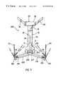
- FIG. 1is a top view of a chest exercise apparatus in accordance with the present invention.
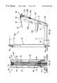
- FIG. 2is a cross sectional view of the chest exercise apparatus along the line II—II in FIG. 3 .
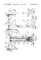
- FIG. 3is a side view of the chest exercise apparatus shown in FIG. 1 .
- FIG. 4is a perspective view of a pivoting pulley in accordance with the present invention.
- FIG. 5is a top view of the shoulder exercise apparatus in accordance with the present invention.
- FIG. 6is a cross sectional view of the shoulder exercise apparatus along the line VI—VI in FIG. 7 .
- FIG. 7is a side view of the shoulder exercise apparatus shown in FIG. 5 .
- FIG. 8is a top view of an abdominal exercise apparatus in accordance with the present invention.
- FIG. 9is a cross sectional view of the abdominal exercise apparatus along the line IX—IX in FIG. 10 .
- FIG. 10is a side view of the abdominal exercise apparatus as shown in FIG. 8 .
- FIG. 11is a top view of a biceps exercise apparatus in accordance with the present invention.
- FIG. 12is a cross sectional view of the biceps exercise along the line XII—XII in FIG. 13 .
- FIG. 13is a side view of a biceps exercise apparatus as shown in FIG. 10 .
- FIG. 14is a perspective view of a triceps exercise apparatus in accordance with the present invention.
- FIG. 15is a cross section view of the triceps exercise apparatus along the line XV—XV in FIG. 16 .
- FIG. 16is a side view of the triceps exercise apparatus as shown in FIG. 14 .
- FIG. 17is a top view of a rowing exercise apparatus is in accordance with the present invention.
- FIG. 18is a cross sectional view of the rowing exercise apparatus along the line XVIII—XVIII in FIG. 19 .
- FIG. 19is a side view of the rowing exercise apparatus as shown in FIG. 17 .
- FIG. 20is a detailed view of the leg support used in conjunction with the rowing exerciser apparatus.
- FIG. 21is a top view of a lat exercise apparatus in accordance with the present invention.
- FIG. 22is a cross sectional view of the lat exercise apparatus along the line XXII—XXII in FIG. 23 .
- FIG. 23is a side view of the lat exercise apparatus as shown in FIG. 22 .
- a family of exercise apparatusesis disclosed. Each member of the family is adapted for targeting a specific body part, or parts. However, and as discussed above in the Background of the Invention, the various exercise apparatuses making up the present family each include a substantially identical base structure around which the various exercise apparatuses are designed and constructed.
- Each exercise apparatusis constructed with a base structure 10 including a central support member 12 having a first end 14 to which a user support structure 16 is secured and a second end 18 to which a weight stack 20 is secured.
- a single cable 22actuates the weight stack 20 .
- the single cable 22is secured to the weight stack 20 for movement by an individual using a distinct exercise apparatus.
- Each apparatusfurther includes first and second support sleeves selectively secured to the base structure 16 for directing first and second strands 28 , 30 (i.e., opposite strands) of the cable 22 to a predetermined position for engagement by a user.
- the central support member 12is preferably a tubular member.
- the tubular construction of the central support member 12permits designers to pass the opposite cable strands 28 , 30 therethrough to facilitate the adaptation of the base structure 10 for targeting various body parts.
- the central support member 12is formed from steel, although those skilled in the art will appreciate the other materials which may be used in the construction of the disclosed exercise apparatuses without departing from the spirit of the present invention.
- the weight stack 20 secured to the second end 18 of the central support member 12is a generally conventional weight stack and includes vertical support members 32 aligning to support a stack of weight plates 34 to be moved via a pulley system which will be discussed below in greater detail.
- the weight stack 20is covered by a protective sleeve 36 positioned about the weight stack 20 .
- the weight stack 20is actuated by a single cable 22 which controls the movement of the weight stack 20 .
- the central portion 38 of the cable 22is passed through a first pulley 40 .
- a coupling member 42directly couples the stack of weight plates 34 to the first pulley 40 in a conventional manner.
- Opposite strands 28 , 30 of the cable 22then respectively extend over first and second upper pulleys 44 , 46 before passing over first and second lower pulleys 48 , 50 .
- the cable 22merely passes over the upper pulleys 44 , 46 before being positioned for engagement by the user.
- a variation such as thisdoes not limit the functionality of the present base structure 10 , as the variation only requires bypassing the lower pulleys 48 , 50 without modifying the base structure 10 itself.
- the angular orientation of the various pulleysmay be readily adjusted to accommodate the various apparatuses making up the present invention. In this way, the cable 22 may be readily oriented to suit the needs of specific apparatuses.
- the respective first and second strands 28 , 30 of the cable 22pass through the opening formed in the central support member and toward the first end 14 of the central support member 12 .
- the first and second strands 28 , 30 of the cableexit the central support member 12 for positioning in accordance with the specific use for which the base structure 10 is being applied.
- the respective ends 52 , 54 of the first and second strands 28 , 30are each provided with stop members 56 .
- the stop members 56control motion of the single cable 22 to allow exercise by pulling the first strand 28 alone, the second strand 30 alone, or both strands at the same time.
- First and second lateral support membersare also secured to the second end 18 of the central support member 12 .
- the lateral support members 58 , 60extend outwardly from the longitudinal axis of the central support member 12 and away from the first end 14 of the central support member 12 .
- the combination of the cental support member 12 , the first lateral support 58 and the second lateral support 60create a tripod foundation structure. This foundation structure supports the remaining components of the present exercise apparatuses, as well as users of the present exercise apparatuses.
- each specific family memberis created by selectively mounting desired support sleeves at various locations along the base structure 10 .
- various exercise apparatusesare created from a single base structure 10 by orienting support sleeves for access along general motion lines.
- Each of the family membersis discussed in below in detail. The following disclosure is not intended to be exhaustive of the many exercise apparatuses which may be manufactured from the disclosed base structure 10 , but merely as exemplary of the various apparatuses which may be fabricated in accordance with the present invention.
- a base structure 10which may be readily used in the manufacture of distinct exercise apparatuses facilitates a novel method for the manufacture of exercise apparatuses.
- a family of exercise apparatuses designed to target a variety of muscle groupsis manufactured by first creating a base structure 10 dimensioned for use in the development of a variety of distinct exercise apparatuses designed to target different muscle groups.
- the base structure 10includes a central support member 12 having a first end 14 to which a user support structure 16 is secured and a second end 18 to which a weight stack 20 is secured, wherein the weight stack 20 is actuated by a single cable 22 secured thereto for movement by an individual using a distinct exercise apparatus.
- First and second lateral support sleevesare then secured to the base structure 10 at distinct positions. The first and second support sleeves direct opposite strands 52 , 54 of the cable 22 to predetermined positions for engagement by a user to perform various exercises targeting different muscle groups.
- the chest exercise apparatus 100includes the base structure 10 discussed above.
- the base structure 10In order to accommodate the chest exercises being performed on the disclosed apparatus, the base structure 10 , and specifically the user support structure 16 , include a full seat 102 with an inclined backrest 104 .
- the seat 102is vertically adjustable to accommodate users of various sizes. While the present vertical adjustment mechanism is not critical to the invention disclosed in the present application, those skilled in the art will appreciate the variety of adjustment mechanism which may be used within the spirit of the present invention.
- the backrest 104is inclined at approximately an angle of 20°. While the specific orientation of the backrest 104 is considered ideal for the preferred embodiment of the present invention, it should be appreciated that the backrest 104 may be oriented at a variety of angles without departing from the spirit of the present invention.
- the backrest 104provides the support necessary for performing chest exercises as an individual faces toward the weight stack 20 in accordance with the preferred embodiment of the present invention. While a specific seat structure is disclosed in accordance with the present invention, other seat structures may be employed without departing from the spirit of the present invention.
- the single cable 22 coupled to the weight stack 20extends from the weight stack 20 and through the center of the central support member 12 toward the first end 14 of the central support member 12 .
- the respective strands 28 , 30 of the cable 22are guided along the back surface 106 of the support column 114 of seat 102 by a series of pulleys to first and second support sleeves 108 , 110 extending from opposite sides of the backrest 104 .
- each strand 28 , 30 of the cablerespectively engages a parallel oriented pulley 112 a , 112 b positioned adjacent the first end 14 of the central support member 12 .
- Each strand 28 , 30 of the cable 22then engages a transversely oriented pulley 116 a , 116 b positioned midway up the support column 114 .
- the transversely oriented pulleys 116 a , 116 bdirect the cable 22 into respective first and second support sleeves 108 , 110 .
- the support sleeves 108 , 110extend upwardly and outwardly such that the distal end 118 , 120 of each of the first and second support sleeves 108 , 110 terminates at a position approximately in line with the top portion of the backrest 104 and the extended elbows of an individual using the present chest exercise apparatus 100 .
- the distal ends 118 , 120 of the first and second support sleeves 108 , 110are positioned approximately 40 inches above the central support member 12 as the support sleeves 108 , 110 respectively extend upwardly at an angle of 25° with respect to a horizontal plane and rearwardly at an angle of 5° with respect to a vertical plane.
- First and second pivoting pulleys 122 , 124are respectively coupled to the distal ends 118 , 120 of the first and second support sleeves 108 , 110 .
- the strands 28 , 30 of the cable 22respectively exit the first and second support sleeves 108 , 110 , pass over the pivoting pulleys 122 , 124 and are ready for engagement by the user.
- the distal end 52 , 54 of each strand 28 , 30 of the cable 22may be fitted with a wide variety of grips known to those skilled in the art.
- Each pivoting pulley 122 , 124includes a frame 126 with a central pivot 128 for rotatably supporting a pulley member 130 .
- the frame 126is formed so as to cover the pulley member 130 and thereby prevent undesired access with the pulley member 130 as the cable 22 passes thereover.
- the frame 126is further provided with a counterweight 131 opposite the pulley member 130 .
- the frame 126further includes a cylindrical coupling member 132 shaped and dimensioned for pivotal attachment to the distal end 118 , 120 of a support sleeve 108 , 110 .
- the cylindrical coupling member 132provides an opening through which the cable 22 passes as it extends from the support sleeve 108 , 110 toward the pulley member 130 . In this way, the cable 22 passes along the axis about which the pivoting pulley pivots 122 , 124 relative to the support sleeve 108 , 110 to provide greater freedom of motion as an individual attempts to draw the cable 22 in various directions during exercise.
- pivoting pulley 122 , 124permits a great degree of flexibility with regard to the angle at which the cable 22 is drawn from the support sleeve 108 , 110 , the inclusion of the present pivoting pulleys 122 , 124 at the distal end 118 , 120 of each support sleeve 108 , 110 greatly increases the flexibility of the present exercise apparatus.
- an individualIn use, an individual is seated on the seat facing the weight stack. The individual will then grip the handles at the distal ends of the respective strands of the cable, and push the handles toward the weight stack to generate resistance from the weight stack. As shown in FIGS. 1 to 3 , the flexibility provided by the pivoting pulleys permits the individual to move in a wide variety of paths in order to equally exercise a wide variety of chest muscles.
- the present chest exercise apparatusis designed to be used with the user sitting and facing the weight stack
- the versatility provided by the design of the exercise apparatusprovides users with virtually unlimited possibilities with regard to the range of exercise motions that may be accommodated by the present exercise apparatus.
- a shoulder exercise apparatus 200in accordance with the present invention is disclosed.
- the shoulder exercise apparatus 200includes the base structure 10 discussed above.
- the user support structure 16includes a full seat 202 with an inclined backrest 204 .
- the seat 202is vertically adjustable and the backrest 204 provides support necessary for performing shoulder exercises as an individual faces toward the weight stack 20 in accordance with the preferred embodiment of the present invention. While a specific seat 202 structure is disclosed in accordance with the present invention, other seat structures may be employed without departing from the spirit of the present invention.
- the single cable 22 coupled to the weight stack 20 discussed aboveextends from the weight stack 20 and through the center of the central support member 12 toward the first end 14 of the central support member 12 .
- the respective strands 28 , 30 of the cable 22are directed by respective pulleys 206 , 207 to enter first and second support sleeves 208 , 210 secured to the first end 14 of the central support member 12 .
- the support sleeves 208 , 210extend slightly upwardly and outwardly such that the distal end 218 , 220 of each of the first and second support sleeves 208 , 210 terminates at a position approximately aligned with the shoulder position of an individual who might be utilizing the present shoulder exercise apparatus 200 .
- each support sleeve 208 , 210is positioned approximately 7 inches above the central support member 12 as the support sleeves 208 , 210 respectively extend upwardly at an angle of 10° relative to a horizontal plane and rearwardly at an angle of 7° relative to a vertical plane.
- First and second pivoting pulleys 222 , 224are respectively coupled to the distal ends 218 , 220 of the first and second support sleeves 208 , 210 .
- the strands 28 , 30 of the cable 22respectively exit the first and second support sleeves 208 , 210 , pass over the pivoting pulleys 222 , 224 and are ready for engagement by the user.
- the distal end 52 , 54 of each strand 28 , 30 of the cable 22may be fitted with a wide variety of grips known to those skilled in the art.
- the pivoting pulleys 222 , 224are identical to those discussed above with reference to FIG. 4 .
- an individualwill be seated on the seat facing the weight stack. The individual will then grip the handles at the distal end of each strand and push the handles upwardly to generate resistance from the weight stack.
- the flexibility provided by the pivoting pulleyspermits the individual to move in a wide variety of paths in order to equally exercise a wide variety of shoulder muscles.
- the present shoulder exercise apparatusis designed to be used with the user sitting and facing the weight stack
- the versatility provided by the design of the exercise apparatusprovides users with virtually unlimited possibilities with regard to the range of exercise motions that may be accommodated by the present exercise apparatus.
- an abdominal exercise apparatus 300in accordance with the present invention is disclosed.
- the abdominal exercise apparatus 300includes the base structure 10 discussed above.
- the base structure 10includes a user support structure 16 with an inclined backrest 304 similar to that disclosed with regard to the chest exercise apparatus 100 .
- the backrest 304provides the support necessary for performing abdominal exercises as an individual faces toward the weight stack 20 in accordance with the preferred embodiment of the present invention. While a specific seat 302 structure is disclosed in accordance with the present invention, other seat structures may be employed without departing from the spirit of the present invention.
- the single cable 22 coupled to the weight stack 20extends from the weight stack 20 and through the center of the central support member 12 toward the first end 14 of the central support member 12 .
- the respective strands 28 , 30 of the cable 22are guided along the back surface of a support column 314 of the seat 302 by a series of pulleys to first and second support sleeves 308 , 310 extending from opposite sides of the seat backrest 304 .
- the strands 28 , 30 of the cable 22are respectively guided by a first pair of pulleys 312 a , 312 b directing the cable 22 along the support column 314 .
- the strands 28 , 30 of the cable 22are then guided by a pair of transversely oriented pulleys 316 a , 316 b into the first and second support sleeves 308 , 310 .
- the first and second support sleeves 308 , 310extend upwardly and outwardly such that the distal end 318 , 320 of each support sleeve 308 , 310 terminates at a position approximately in line with the top portion of the seat backrest 304 and in line with the shoulders of an individual utilizing the present apparatus.
- each support sleeve 308 , 310is positioned approximately 50 inches above the central support member 12 as the support sleeves 308 , 310 respectively extend upwardly at and angle of 60° relative to a horizontal plane and rearwardly at an angle of 0° relative to a vertical plane.
- First and second pivoting pulleys 322 , 324are respectively coupled to distal ends 318 , 320 of the first and second support sleeves 308 , 310 .
- the strands 28 , 30 of the cable 22respectively exit the first and second support sleeves 308 , 310 pass over the pivoting pulleys 322 , 324 and are ready for engagement by the user.
- the distal end 52 , 54 of each strand 28 , 30 of the cable 22may be fitted to a wide variety of grips known to those skilled in art.
- the pivoting pulleysare the same as those disclosed in FIG. 4 .
- an individualIn use, an individual will be seated on the seat facing the weight stack. The individual will then grip the handles at the distal ends at the respective ends of the cable, and push the handles toward the weight stack to generate resistance from the weight stack. As shown in FIGS. 8 to 10 , the flexibility provided by the pivoting pulleys permits the individual to move in a wide variety of paths in order to equally exercise a wide variety of abdominal muscles.
- the present abdominal exercise apparatusis designed to be used with the user sitting and facing the weight stack
- the versatility provided by the design of the exercise apparatusprovides users with virtually unlimited possibilities with regard to the range of exercise motions that may be accommodated by the present exercise apparatus.
- a biceps exercise apparatus 400in accordance with present invention is disclosed.
- the biceps exercise apparatus 400includes the base structure 10 discussed above.
- the biceps exercise apparatus 400includes a simple seat 402 for supporting an individual.
- the seat 402 structuredoes not include a backrest since individuals utilizing the biceps exercise apparatus 400 will not require back support during the exercise.
- the single cable 22 coupled to the weight stack 20extends from the weight stack 20 and through the first and second lower pulleys 48 , 50 discussed above.
- the strands 28 , 30 of the cable 22do not extend through the central support member 12 . Rather, the strands 28 , 30 of the cable 22 extend into support sleeves 408 , 410 directly secured at the second end 18 of the central support member 12 .
- the support sleeves 408 , 410extend outwardly from the longitudinal axis of the central support member 12 and slightly toward the first end 14 of the central support member 12 .
- the distal end 418 , 420 of each of the first and second sleeves 408 , 410terminates at a position substantially outside the shoulder width of an individual who might be utilizing the exercise apparatus.
- the distal ends 418 , 420 of the first and second support sleeves 408 , 410tip up 5 inches from the ground while the support sleeves 408 , 410 respectively extend rearwardly at an angle of 25° relative to a vertical plane for a distance of approximately 15 inches.
- first and second pivoting pulleys 422 , 424are respectively coupled to the distal ends 418 , 422 of the first and second support sleeve 408 , 410 .
- the strands 28 , 30 of the cable 22respectively exit the first and second support sleeves 408 , 410 , pass over the pivoting pulleys 422 , 424 and are ready for engagement by the user.
- the pivoting pulleys 422 , 424are shown in greater detail in FIG. 4, and are discussed above.
- the distal ends 52 , 54 of each strand 28 , 30 of the cable 22may be fitted with a wide variety of grips known to those skilled in the art.
- an individualIn use, an individual will be seated on the seat facing the weight stack. The individual will then grip the handles at the distal ends of the respective ends of the cable, and pull the handle toward himself or herself to generate resistance from the weight stack. As shown in FIGS. 10 to 13 , the flexibility provided by the pivoting pulleys permits the individual to move in a wide variety of paths in order to equally exercise a wide variety of biceps muscles.
- the present biceps exercise apparatusis designed to be used with the user sitting and facing the weight stack
- the versatility provided by the design of the exercise apparatusprovides users with virtually unlimited possibilities with regard to the range of exercise motions that may be accommodated by the present exercise apparatus.
- a triceps exercise apparatus 500in accordance the present invention is disclosed.
- the triceps exercise apparatus 500includes the base structure 10 discussed above.
- the triceps exercise apparatus 500merely discloses a simple seat 502 for supporting a user. While a specific seat 502 structure is disclosed in accordance with the present invention, other seat structures may be employed without departing from the spirit of the present invention.
- the single cable 22 coupled to the weight stack 20does not extend through the first and second lower pulleys 48 , 50 as in the exercise apparatuses discussed above. Rather, the strands 28 , 30 of the cable 22 exit the first and second upper pulleys 44 , 46 and move directly to first and second support sleeves 508 , 510 secured at the upper end 62 of the weight stack 20 .
- the first and second support sleeves 508 , 510extend outwardly from the upper end 62 of the weight stack 20 such that the distal end 518 , 520 of each of the first and second support sleeve 518 , 520 terminates at a position approximately in line with the shoulders of an individual utilizing the present triceps exercise apparatus 500 . Given that the support sleeves 508 , 510 are secured at the upper end 62 of the weight stack 20 , the distal end 518 , 520 of each of the first and second support sleeve 508 , 510 will be slightly above the shoulders, and probably head, of an individual utilizing the present exercise apparatus.
- the first and second support sleeves 508 , 510extend outwardly perpendicular to the longitudinal axis of the weight stack 20 and within the horizontal plane in which the weight stack 20 sits.
- the first and second support sleeves 508 , 510extend outwardly a distance of 25 inches.
- First and second pivoting pulleys 522 , 524are respectively coupled to the distal ends 518 , 520 of the first and second support sleeves 508 , 510 .
- the strands 28 , 30 of the cable 22respectively exit the first and second support sleeves 508 , 510 , pass over the pivoting pulleys 522 , 524 and are ready for engagement by the user.
- the distal ends 52 , 54 of each strand 28 , 30 of the cable 22may be fitted with a wide variety of grips known to those skilled in the art.
- the pivoting pulleys 522 , 524are identical to those employed in the other exercise apparatuses and are shown in greater detail in FIG. 4 .
- the individualwill be seated on the seat facing the weight stack. The individual will then grip the handles at the distal ends of the respective ends of the cable, and push the handles toward the ground to generate resistance from the weight stack.
- the flexibility provided by the pivoting pulleyspermits the individual to move in a wide variety of paths in order to equally exercise a wide variety of triceps muscles.
- the present triceps exercise apparatusis designed to be used with the user sitting and facing the weight stack, the versatility provided by the design of the exercise apparatus provides users with virtually unlimited possibilities with regard to the range of exercise motions that may be accommodated by the present exercise apparatus.
- a rowing exercise apparatus 600in accordance with the present invention is disclosed.
- the rowing exercise apparatus 600is substantially identical to the triceps exercise apparatus 500 and as such only the use of the device will be disclosed herein.
- the rowing exercise apparatus 600is provided with a leg support 630 adjacent the user support 16 .
- the leg support 630includes an upwardly extending post 632 with a vertical bar 634 secured to its upper end.
- Pads 636 , 637are secured to the vertical bar and directed downwardly to engage the knees of an individual using the device.
- the pads 636 , 637are adjustably mounted within respective slots 638 , 640 formed in the vertical bar 634 . In this way, the pads 636 , 637 may be adjusted to accommodate users of varying sizes.
- an individualIn use, an individual will be seated on the seat facing the weight stack. The individual will then grip the handles at the distal ends of the respective ends of the cable, and pull the handles toward his or her chest to generate resistance from the weight stack. As shown in FIGS. 17 to 20 , the flexibility provided by the pivoting pulleys permits the individual to move in a wide variety of paths in order to equally exercise a wide variety of muscles.
- a lat exercise apparatus 700 in accordance the present inventionis disclosed.
- the lat exercise apparatus 700includes the base structure 10 discussed above.
- the lat exercise apparatus 700merely discloses a simple seat 702 for supporting a user. While a specific seat 702 structure is disclosed in accordance with the present invention, other seat structures may be employed without departing from the spirit of the present invention.
- the single cable 22 coupled to the weight stack 20does not extend through the first and second lower pulleys 48 , 50 as in the exercise apparatuses discussed above. Rather, the strands 28 , 30 of the cable 22 exit the first and second upper pulleys 44 , 46 and move directly to first and second support sleeves 708 , 710 secured at the upper end 62 of the weight stack 20 .
- the first and second support sleeve 708 , 710extend outwardly, upwardly and rearwardly from the upper end of the weight stack 20 such that the distal ends 718 , 720 of each of the first and second support sleeves 708 , 710 terminates at a position above the top of the weight stack 20 and the shoulders of an individual utilizing the present lat exercise apparatus 700 .
- the distal ends 718 , 720 of the first and second support sleeves 718 , 720are positioned approximately 80 inches above the central support member as the support sleeves respectively extend upwardly at an angle of 15° relative to a horizontal plane and rearwardly at an angle of 40° relative to a vertical plane.
- First and second pivoting pulleys 722 , 724are respectively coupled to the distal ends 718 , 720 of the first and second support sleeves 708 , 710 .
- the strands 28 , 30 of the cable 22respectively exit the first and second support sleeves 708 , 710 , pass over the pivoting pulleys 722 , 724 and are ready for engagement by the user.
- the distal ends 52 , 54 of each strand 28 , 30 of the cable 22may be fitted with a wide variety of grips known to those skilled in the art.
- the pivoting pulleys 722 , 724are identical to those employed in the other exercise apparatuses and are shown in greater detail in FIG. 4 .
- the individualwill be seated on the seat facing the weight stack. The individual will then grip the handles at the distal ends of the respective ends of the cable, and pull the handles toward his or her chest to generate resistance from the weight stack.
- the flexibility provided by the pivoting pulleyspermits the individual to move in a wide variety of paths in order to equally exercise a wide variety of lat muscles.
- the present lat exercise apparatusis designed to be used with the user sitting and facing the weight stack
- the versatility provided by the design of the exercise apparatusprovides users with virtually unlimited possibilities with regard to the range of exercise motions that may be accommodated by the present exercise apparatus.
Landscapes
- Health & Medical Sciences (AREA)
- Orthopedic Medicine & Surgery (AREA)
- General Health & Medical Sciences (AREA)
- Physical Education & Sports Medicine (AREA)
- Life Sciences & Earth Sciences (AREA)
- Biophysics (AREA)
- Rehabilitation Tools (AREA)
- Supplying Of Containers To The Packaging Station (AREA)
- Centrifugal Separators (AREA)
- Control Of Multiple Motors (AREA)
- Eye Examination Apparatus (AREA)
- Pharmaceuticals Containing Other Organic And Inorganic Compounds (AREA)
Abstract
Description
Claims (22)
Priority Applications (12)
| Application Number | Priority Date | Filing Date | Title |
|---|---|---|---|
| US09/379,307US6387020B1 (en) | 1999-08-23 | 1999-08-23 | Exercise apparatus |
| US09/437,316US6171219B1 (en) | 1999-08-23 | 1999-11-10 | Calf exercise apparatus |
| US09/437,317US6422980B1 (en) | 1999-08-23 | 1999-11-10 | Standing abdominal exercise apparatus |
| DE60043514TDE60043514D1 (en) | 1999-08-23 | 2000-08-18 | exercise machine |
| AU67654/00AAU6765400A (en) | 1999-08-23 | 2000-08-18 | Exercise apparatus |
| HK03101066.4AHK1049455A1 (en) | 1999-08-23 | 2000-08-18 | Exercise apparatus |
| PCT/US2000/021968WO2001014016A2 (en) | 1999-08-23 | 2000-08-18 | Exercise apparatus |
| AT00955447TATE451150T1 (en) | 1999-08-23 | 2000-08-18 | EXERCISE DEVICE |
| DE10084523TDE10084523T1 (en) | 1999-08-23 | 2000-08-18 | exerciser |
| DE20022662UDE20022662U1 (en) | 1999-08-23 | 2000-08-18 | exerciser |
| EP00955447AEP1276543B1 (en) | 1999-08-23 | 2000-08-18 | Exercise apparatus |
| US10/010,780US6712740B2 (en) | 1999-08-23 | 2001-12-06 | Exercise apparatus |
Applications Claiming Priority (1)
| Application Number | Priority Date | Filing Date | Title |
|---|---|---|---|
| US09/379,307US6387020B1 (en) | 1999-08-23 | 1999-08-23 | Exercise apparatus |
Related Child Applications (2)
| Application Number | Title | Priority Date | Filing Date |
|---|---|---|---|
| US09/437,317Continuation-In-PartUS6422980B1 (en) | 1999-08-23 | 1999-11-10 | Standing abdominal exercise apparatus |
| US09/437,316Continuation-In-PartUS6171219B1 (en) | 1999-08-23 | 1999-11-10 | Calf exercise apparatus |
Publications (1)
| Publication Number | Publication Date |
|---|---|
| US6387020B1true US6387020B1 (en) | 2002-05-14 |
Family
ID=23496705
Family Applications (1)
| Application Number | Title | Priority Date | Filing Date |
|---|---|---|---|
| US09/379,307Expired - LifetimeUS6387020B1 (en) | 1999-08-23 | 1999-08-23 | Exercise apparatus |
Country Status (7)
| Country | Link |
|---|---|
| US (1) | US6387020B1 (en) |
| EP (1) | EP1276543B1 (en) |
| AT (1) | ATE451150T1 (en) |
| AU (1) | AU6765400A (en) |
| DE (3) | DE10084523T1 (en) |
| HK (1) | HK1049455A1 (en) |
| WO (1) | WO2001014016A2 (en) |
Cited By (63)
| Publication number | Priority date | Publication date | Assignee | Title |
|---|---|---|---|---|
| US20020035017A1 (en)* | 2000-05-03 | 2002-03-21 | Victor Pertegaz-Esteban | Exercise equipment with multi-positioning handles |
| US20040072659A1 (en)* | 2002-09-30 | 2004-04-15 | Nerio Alessandri | Exercising machine |
| US20040082444A1 (en)* | 2002-08-08 | 2004-04-29 | Nautilus, Inc. | Dual-direction pulley system |
| US20050032611A1 (en)* | 2003-08-04 | 2005-02-10 | Webber Randall T. | Self-aligning pivoting seat exercise machine |
| US20050096196A1 (en)* | 2003-11-03 | 2005-05-05 | Webber Randall T. | Shoulder press exercise machine |
| US20050096198A1 (en)* | 2003-10-31 | 2005-05-05 | Webber Randall T. | Triceps dip exercise machine |
| US20050096197A1 (en)* | 2003-11-03 | 2005-05-05 | Webber Randall T. | Rigid arm pull down exercise machine |
| US20060128535A1 (en)* | 2004-12-13 | 2006-06-15 | Nautilus, Inc. | Arm assembly for exercise devices |
| US7083554B1 (en) | 1997-02-27 | 2006-08-01 | Nautilus, Inc. | Exercise machine with infinite position range limiter and automatic belt tensioning system |
| USD533910S1 (en) | 2005-03-15 | 2006-12-19 | Nautilus, Inc. | Exercise device |
| US20070293378A1 (en)* | 2003-08-04 | 2007-12-20 | Webber Randall T | Chest press exercise machine with self-aligning pivoting user support |
| US20070293377A1 (en)* | 2003-08-04 | 2007-12-20 | Webber Randall T | Lat exercise machine with self-aligning pivoting user support |
| US20080058181A1 (en)* | 2006-09-06 | 2008-03-06 | Webber Randall T | Arm exercise machine with self-aligning pivoting user support |
| US20080058177A1 (en)* | 2006-09-05 | 2008-03-06 | Webber Randall T | Leg exercise machine with self-aligning pivoting seat |
| US20080058176A1 (en)* | 2006-09-05 | 2008-03-06 | Webber Randall T | Chest press exercise machine with self-aligning pivoting user support |
| US20090036277A1 (en)* | 2007-08-02 | 2009-02-05 | Vectra Fitness, Inc. | Functional Training Exercise Apparatus and Methods |
| US20100009818A1 (en)* | 2008-07-09 | 2010-01-14 | Tom Simonson | Multi Axes Exercise Apparatus |
| US20100156760A1 (en)* | 2008-12-19 | 2010-06-24 | At&T Intellectual Property I, L.P. | Motion controlled multimedia content viewing method and system |
| US7938760B1 (en) | 2008-10-17 | 2011-05-10 | Hoist Fitness Systems, Inc. | Exercise machine with lifting arm |
| US7981010B1 (en) | 2003-08-04 | 2011-07-19 | Hoist Fitness Systems, Inc. | Exercise machine with multi-function user engagement device |
| US7993251B1 (en) | 2003-08-04 | 2011-08-09 | Hoist Fitness Systems, Inc. | Pectoral fly exercise machine |
| US20110207584A1 (en)* | 2010-02-25 | 2011-08-25 | Hoist Fitness Systems, Inc. | Calf Exercise Machine With Rocking User Support |
| US20110224058A1 (en)* | 2010-03-05 | 2011-09-15 | Hoist Fitness Systems, Inc. | Thigh exercise machine with rocking user support |
| US8734304B2 (en) | 2010-03-04 | 2014-05-27 | Hoist Fitness Systems, Inc. | Low back exercise machine with rocking user support |
| US9539458B1 (en)* | 2016-03-15 | 2017-01-10 | Michael Peter Ross | Multi-positioning exercise machine with dynamic resistance |
| US10449416B2 (en) | 2015-08-26 | 2019-10-22 | Icon Health & Fitness, Inc. | Strength exercise mechanisms |
| US10561894B2 (en) | 2016-03-18 | 2020-02-18 | Icon Health & Fitness, Inc. | Treadmill with removable supports |
| US10709925B2 (en) | 2013-03-14 | 2020-07-14 | Icon Health & Fitness, Inc. | Strength training apparatus |
| US10758767B2 (en) | 2013-12-26 | 2020-09-01 | Icon Health & Fitness, Inc. | Resistance mechanism in a cable exercise machine |
| US10786706B2 (en) | 2018-07-13 | 2020-09-29 | Icon Health & Fitness, Inc. | Cycling shoe power sensors |
| US10864407B2 (en) | 2016-03-18 | 2020-12-15 | Icon Health & Fitness, Inc. | Coordinated weight selection |
| US10918905B2 (en) | 2016-10-12 | 2021-02-16 | Icon Health & Fitness, Inc. | Systems and methods for reducing runaway resistance on an exercise device |
| US10940360B2 (en) | 2015-08-26 | 2021-03-09 | Icon Health & Fitness, Inc. | Strength exercise mechanisms |
| US10953305B2 (en) | 2015-08-26 | 2021-03-23 | Icon Health & Fitness, Inc. | Strength exercise mechanisms |
| US10994173B2 (en) | 2016-05-13 | 2021-05-04 | Icon Health & Fitness, Inc. | Weight platform treadmill |
| US11000730B2 (en) | 2018-03-16 | 2021-05-11 | Icon Health & Fitness, Inc. | Elliptical exercise machine |
| US11033777B1 (en) | 2019-02-12 | 2021-06-15 | Icon Health & Fitness, Inc. | Stationary exercise machine |
| US11058913B2 (en) | 2017-12-22 | 2021-07-13 | Icon Health & Fitness, Inc. | Inclinable exercise machine |
| US11058914B2 (en) | 2016-07-01 | 2021-07-13 | Icon Health & Fitness, Inc. | Cooling methods for exercise equipment |
| US11187285B2 (en) | 2017-12-09 | 2021-11-30 | Icon Health & Fitness, Inc. | Systems and methods for selectively rotationally fixing a pedaled drivetrain |
| US11298577B2 (en) | 2019-02-11 | 2022-04-12 | Ifit Inc. | Cable and power rack exercise machine |
| US11326673B2 (en) | 2018-06-11 | 2022-05-10 | Ifit Inc. | Increased durability linear actuator |
| US11451108B2 (en) | 2017-08-16 | 2022-09-20 | Ifit Inc. | Systems and methods for axial impact resistance in electric motors |
| US11534654B2 (en) | 2019-01-25 | 2022-12-27 | Ifit Inc. | Systems and methods for an interactive pedaled exercise device |
| US11534651B2 (en) | 2019-08-15 | 2022-12-27 | Ifit Inc. | Adjustable dumbbell system |
| US11673036B2 (en) | 2019-11-12 | 2023-06-13 | Ifit Inc. | Exercise storage system |
| US11700905B2 (en) | 2014-03-10 | 2023-07-18 | Ifit Inc. | Pressure sensor to quantify work |
| US11794070B2 (en) | 2019-05-23 | 2023-10-24 | Ifit Inc. | Systems and methods for cooling an exercise device |
| US11850497B2 (en) | 2019-10-11 | 2023-12-26 | Ifit Inc. | Modular exercise device |
| US11878199B2 (en) | 2021-02-16 | 2024-01-23 | Ifit Inc. | Safety mechanism for an adjustable dumbbell |
| US11931618B2 (en) | 2021-08-06 | 2024-03-19 | Hoist Fitness Systems, Inc. | Locking mechanism for simultaneously positioning an exercise arm in two perpendicular directions |
| US11931621B2 (en) | 2020-03-18 | 2024-03-19 | Ifit Inc. | Systems and methods for treadmill drift avoidance |
| US11951377B2 (en) | 2020-03-24 | 2024-04-09 | Ifit Inc. | Leaderboard with irregularity flags in an exercise machine system |
| US12029935B2 (en) | 2021-08-19 | 2024-07-09 | Ifit Inc. | Adjustment mechanism for an adjustable kettlebell |
| US12029961B2 (en) | 2020-03-24 | 2024-07-09 | Ifit Inc. | Flagging irregularities in user performance in an exercise machine system |
| US12176009B2 (en) | 2021-12-30 | 2024-12-24 | Ifit Inc. | Systems and methods for synchronizing workout equipment with video files |
| US12219201B2 (en) | 2021-08-05 | 2025-02-04 | Ifit Inc. | Synchronizing video workout programs across multiple devices |
| US12263371B2 (en) | 2021-04-27 | 2025-04-01 | Ifit Inc. | Devices, systems, and methods for rotating a tread belt in two directions |
| US12280294B2 (en) | 2021-10-15 | 2025-04-22 | Ifit Inc. | Magnetic clutch for a pedaled drivetrain |
| US12350573B2 (en) | 2021-04-27 | 2025-07-08 | Ifit Inc. | Systems and methods for cross-training on exercise devices |
| US12350547B2 (en) | 2022-02-28 | 2025-07-08 | Ifit Inc. | Devices, systems, and methods for moving a movable step through a transition zone |
| US12409375B2 (en) | 2022-03-18 | 2025-09-09 | Ifit Inc. | Systems and methods for haptic simulation in incline exercise devices |
| US12433815B2 (en) | 2020-10-02 | 2025-10-07 | Ifit Inc. | Massage roller with pressure sensors |
Families Citing this family (1)
| Publication number | Priority date | Publication date | Assignee | Title |
|---|---|---|---|---|
| EP2155340B1 (en) | 2007-12-21 | 2011-07-20 | Cybex International, Inc. | Exercise apparatus and method with selectively variable stabilization |
Citations (12)
| Publication number | Priority date | Publication date | Assignee | Title |
|---|---|---|---|---|
| US353089A (en) | 1836-08-10 | 1886-11-23 | John alexaedeb smith | |
| US457400A (en) | 1891-08-11 | Exercising apparatus | ||
| US1928089A (en) | 1929-07-29 | 1933-09-26 | Blickman Inc | Exercising apparatus |
| US2436987A (en) | 1944-10-02 | 1948-03-02 | Paul A Bailleaux | Exercising apparatus |
| US2977120A (en) | 1959-06-30 | 1961-03-28 | Wesley B Morris | Exercising device |
| US4603855A (en) | 1981-01-02 | 1986-08-05 | Sebelle Leslie W | Variable exercise apparatus |
| US4635926A (en)* | 1983-12-27 | 1987-01-13 | Minkow Roger E | Weight lifting type exercising device |
| US4826157A (en) | 1986-12-10 | 1989-05-02 | Fitzpatrick Patrick C | Physical exercising apparatus |
| US4907798A (en) | 1988-12-06 | 1990-03-13 | Burchatz Rory J | Multi function exercise machine |
| US4974838A (en) | 1989-09-27 | 1990-12-04 | Sollenberger Carl E | Exercise apparatus for performing free weight barbell exercises |
| US5267930A (en)* | 1993-01-06 | 1993-12-07 | Henes Richard W | Exercise machine employing improved leg and foot exercising fixture |
| US5738616A (en) | 1995-05-08 | 1998-04-14 | Robertson; Richard C. | Rotator cuff exercise machine |
Family Cites Families (7)
| Publication number | Priority date | Publication date | Assignee | Title |
|---|---|---|---|---|
| US321388A (en)* | 1885-06-30 | ruebsam | ||
| US2472391A (en)* | 1944-08-09 | 1949-06-07 | Luis G Albizu | Clinical exercise table |
| US4697809A (en)* | 1985-10-16 | 1987-10-06 | Diversified Products Corp. | Cable-operated exerciser |
| SU1725744A3 (en)* | 1990-05-14 | 1992-04-07 | Е. А. Широбоков | Apparatus for exercising muscles |
| US5362290A (en)* | 1993-06-30 | 1994-11-08 | Huang Shih Pin | Multi-purpose exerciser having a clutch means |
| DE19801672A1 (en)* | 1997-02-06 | 1998-11-26 | Matthias Bossert | Multi-gym training apparatus with rope-and-pulley operated weights |
| US5931767A (en)* | 1997-09-11 | 1999-08-03 | Morales; Luis | Shoulder exercise machine |
- 1999
- 1999-08-23USUS09/379,307patent/US6387020B1/ennot_activeExpired - Lifetime
- 2000
- 2000-08-18DEDE10084523Tpatent/DE10084523T1/ennot_activeCeased
- 2000-08-18HKHK03101066.4Apatent/HK1049455A1/enunknown
- 2000-08-18DEDE60043514Tpatent/DE60043514D1/ennot_activeExpired - Lifetime
- 2000-08-18AUAU67654/00Apatent/AU6765400A/ennot_activeAbandoned
- 2000-08-18EPEP00955447Apatent/EP1276543B1/ennot_activeExpired - Lifetime
- 2000-08-18DEDE20022662Upatent/DE20022662U1/ennot_activeExpired - Lifetime
- 2000-08-18WOPCT/US2000/021968patent/WO2001014016A2/enactiveApplication Filing
- 2000-08-18ATAT00955447Tpatent/ATE451150T1/ennot_activeIP Right Cessation
Patent Citations (12)
| Publication number | Priority date | Publication date | Assignee | Title |
|---|---|---|---|---|
| US457400A (en) | 1891-08-11 | Exercising apparatus | ||
| US353089A (en) | 1836-08-10 | 1886-11-23 | John alexaedeb smith | |
| US1928089A (en) | 1929-07-29 | 1933-09-26 | Blickman Inc | Exercising apparatus |
| US2436987A (en) | 1944-10-02 | 1948-03-02 | Paul A Bailleaux | Exercising apparatus |
| US2977120A (en) | 1959-06-30 | 1961-03-28 | Wesley B Morris | Exercising device |
| US4603855A (en) | 1981-01-02 | 1986-08-05 | Sebelle Leslie W | Variable exercise apparatus |
| US4635926A (en)* | 1983-12-27 | 1987-01-13 | Minkow Roger E | Weight lifting type exercising device |
| US4826157A (en) | 1986-12-10 | 1989-05-02 | Fitzpatrick Patrick C | Physical exercising apparatus |
| US4907798A (en) | 1988-12-06 | 1990-03-13 | Burchatz Rory J | Multi function exercise machine |
| US4974838A (en) | 1989-09-27 | 1990-12-04 | Sollenberger Carl E | Exercise apparatus for performing free weight barbell exercises |
| US5267930A (en)* | 1993-01-06 | 1993-12-07 | Henes Richard W | Exercise machine employing improved leg and foot exercising fixture |
| US5738616A (en) | 1995-05-08 | 1998-04-14 | Robertson; Richard C. | Rotator cuff exercise machine |
Non-Patent Citations (1)
| Title |
|---|
| Cybek "Modular" Brochure @ 1994.* |
Cited By (111)
| Publication number | Priority date | Publication date | Assignee | Title |
|---|---|---|---|---|
| US7083554B1 (en) | 1997-02-27 | 2006-08-01 | Nautilus, Inc. | Exercise machine with infinite position range limiter and automatic belt tensioning system |
| US7608028B2 (en) | 2000-05-03 | 2009-10-27 | Nautilus, Inc. | Exercise equipment with multi-positioning handles |
| US20020035017A1 (en)* | 2000-05-03 | 2002-03-21 | Victor Pertegaz-Esteban | Exercise equipment with multi-positioning handles |
| US7108641B2 (en) | 2000-05-03 | 2006-09-19 | Nautilus, Inc. | Exercise equipment with multi-positioning handles |
| US7223213B2 (en) | 2002-08-08 | 2007-05-29 | Nautilus, Inc. | Dual-direction pulley system |
| US20040082444A1 (en)* | 2002-08-08 | 2004-04-29 | Nautilus, Inc. | Dual-direction pulley system |
| US20040072659A1 (en)* | 2002-09-30 | 2004-04-15 | Nerio Alessandri | Exercising machine |
| US7670270B2 (en) | 2002-09-30 | 2010-03-02 | Technogym S.P.A. | Exercising machine |
| US7549949B2 (en) | 2003-08-04 | 2009-06-23 | Hoist Fitness Systems, Inc. | Chest press exercise machine with self-aligning pivoting user support |
| US7594880B2 (en) | 2003-08-04 | 2009-09-29 | Hoist Fitness Systems, Inc. | Self-aligning pivoting seat exercise machine |
| US7993251B1 (en) | 2003-08-04 | 2011-08-09 | Hoist Fitness Systems, Inc. | Pectoral fly exercise machine |
| US7794371B2 (en) | 2003-08-04 | 2010-09-14 | Hoist Fitness Systems, Inc. | Lat exercise machine with self-aligning pivoting user support |
| US20070293378A1 (en)* | 2003-08-04 | 2007-12-20 | Webber Randall T | Chest press exercise machine with self-aligning pivoting user support |
| US20070293377A1 (en)* | 2003-08-04 | 2007-12-20 | Webber Randall T | Lat exercise machine with self-aligning pivoting user support |
| US7981010B1 (en) | 2003-08-04 | 2011-07-19 | Hoist Fitness Systems, Inc. | Exercise machine with multi-function user engagement device |
| US20050032611A1 (en)* | 2003-08-04 | 2005-02-10 | Webber Randall T. | Self-aligning pivoting seat exercise machine |
| US20050096198A1 (en)* | 2003-10-31 | 2005-05-05 | Webber Randall T. | Triceps dip exercise machine |
| US7335140B2 (en) | 2003-10-31 | 2008-02-26 | Hoist Fitness Systems | Triceps dip exercise machine |
| US20050096197A1 (en)* | 2003-11-03 | 2005-05-05 | Webber Randall T. | Rigid arm pull down exercise machine |
| US7331911B2 (en) | 2003-11-03 | 2008-02-19 | Hoist Fitness Systems | Shoulder press exercise machine |
| US7361125B2 (en) | 2003-11-03 | 2008-04-22 | Hoist Fitness Systems, Inc. | Rigid arm pull down exercise machine |
| US20050096196A1 (en)* | 2003-11-03 | 2005-05-05 | Webber Randall T. | Shoulder press exercise machine |
| US7775945B2 (en) | 2004-12-13 | 2010-08-17 | Nautilus, Inc. | Arm assembly for exercise devices |
| US20060128535A1 (en)* | 2004-12-13 | 2006-06-15 | Nautilus, Inc. | Arm assembly for exercise devices |
| USD566798S1 (en) | 2005-03-15 | 2008-04-15 | Nautilus, Inc. | Exercise device |
| USD550789S1 (en) | 2005-03-15 | 2007-09-11 | Nautilus, Inc. | Exercise device |
| USD533910S1 (en) | 2005-03-15 | 2006-12-19 | Nautilus, Inc. | Exercise device |
| US7670269B2 (en) | 2006-09-05 | 2010-03-02 | Hoist Fitness Systems, Inc. | Chest press exercise machine with self-aligning pivoting user support |
| US20080058176A1 (en)* | 2006-09-05 | 2008-03-06 | Webber Randall T | Chest press exercise machine with self-aligning pivoting user support |
| US7563209B2 (en) | 2006-09-05 | 2009-07-21 | Hoist Fitness Systems, Inc. | Leg exercise machine with self-aligning pivoting seat |
| US20080058177A1 (en)* | 2006-09-05 | 2008-03-06 | Webber Randall T | Leg exercise machine with self-aligning pivoting seat |
| US20080058181A1 (en)* | 2006-09-06 | 2008-03-06 | Webber Randall T | Arm exercise machine with self-aligning pivoting user support |
| US7654940B2 (en) | 2006-09-06 | 2010-02-02 | Hoist Fitness Systems, Inc. | Arm exercise machine with self-aligning pivoting user support |
| US20090036277A1 (en)* | 2007-08-02 | 2009-02-05 | Vectra Fitness, Inc. | Functional Training Exercise Apparatus and Methods |
| US7909742B2 (en)* | 2007-08-02 | 2011-03-22 | Vectra Fitness, Inc. | Functional training exercise apparatus and methods |
| US20100009818A1 (en)* | 2008-07-09 | 2010-01-14 | Tom Simonson | Multi Axes Exercise Apparatus |
| US7938761B2 (en)* | 2008-07-09 | 2011-05-10 | Tom Simonson | Multi axes exercise apparatus |
| US11759668B2 (en) | 2008-10-17 | 2023-09-19 | Hoist Fitness Systems, Inc. | Exercise machine with lifting arm |
| US11000722B2 (en) | 2008-10-17 | 2021-05-11 | Hoist Fitness Systems, Inc. | Exercise machine with lifting arm |
| US7938760B1 (en) | 2008-10-17 | 2011-05-10 | Hoist Fitness Systems, Inc. | Exercise machine with lifting arm |
| US10646739B2 (en) | 2008-10-17 | 2020-05-12 | Hoist Fitness Systems, Inc. | Exercise machine with lifting arm |
| US10639513B2 (en) | 2008-10-17 | 2020-05-05 | Hoist Fitness Systems, Inc. | Exercise machine with lifting arm |
| US9861850B1 (en) | 2008-10-17 | 2018-01-09 | Hoist Fitness Systems, Inc. | Exercise machine with lifting arm |
| US20100156760A1 (en)* | 2008-12-19 | 2010-06-24 | At&T Intellectual Property I, L.P. | Motion controlled multimedia content viewing method and system |
| US20110207584A1 (en)* | 2010-02-25 | 2011-08-25 | Hoist Fitness Systems, Inc. | Calf Exercise Machine With Rocking User Support |
| US8177693B2 (en) | 2010-02-25 | 2012-05-15 | Hoist Fitness Systems, Inc. | Calf exercise machine with rocking user support |
| US8734304B2 (en) | 2010-03-04 | 2014-05-27 | Hoist Fitness Systems, Inc. | Low back exercise machine with rocking user support |
| US8562496B2 (en) | 2010-03-05 | 2013-10-22 | Hoist Fitness Systems, Inc. | Thigh exercise machine with rocking user support |
| US20110224058A1 (en)* | 2010-03-05 | 2011-09-15 | Hoist Fitness Systems, Inc. | Thigh exercise machine with rocking user support |
| US11338169B2 (en) | 2013-03-14 | 2022-05-24 | IFIT, Inc. | Strength training apparatus |
| US10953268B1 (en) | 2013-03-14 | 2021-03-23 | Icon Health & Fitness, Inc. | Strength training apparatus |
| US11878206B2 (en) | 2013-03-14 | 2024-01-23 | Ifit Inc. | Strength training apparatus |
| US10709925B2 (en) | 2013-03-14 | 2020-07-14 | Icon Health & Fitness, Inc. | Strength training apparatus |
| US10758767B2 (en) | 2013-12-26 | 2020-09-01 | Icon Health & Fitness, Inc. | Resistance mechanism in a cable exercise machine |
| US10967214B1 (en) | 2013-12-26 | 2021-04-06 | Icon Health & Fitness, Inc. | Cable exercise machine |
| US11700905B2 (en) | 2014-03-10 | 2023-07-18 | Ifit Inc. | Pressure sensor to quantify work |
| US10940360B2 (en) | 2015-08-26 | 2021-03-09 | Icon Health & Fitness, Inc. | Strength exercise mechanisms |
| US10449416B2 (en) | 2015-08-26 | 2019-10-22 | Icon Health & Fitness, Inc. | Strength exercise mechanisms |
| US10953305B2 (en) | 2015-08-26 | 2021-03-23 | Icon Health & Fitness, Inc. | Strength exercise mechanisms |
| US9539458B1 (en)* | 2016-03-15 | 2017-01-10 | Michael Peter Ross | Multi-positioning exercise machine with dynamic resistance |
| US10864407B2 (en) | 2016-03-18 | 2020-12-15 | Icon Health & Fitness, Inc. | Coordinated weight selection |
| US11565148B2 (en) | 2016-03-18 | 2023-01-31 | Ifit Inc. | Treadmill with a scale mechanism in a motor cover |
| US11013960B2 (en) | 2016-03-18 | 2021-05-25 | Icon Health & Fitness, Inc. | Exercise system including a stationary bicycle and a free weight cradle |
| US12029943B2 (en) | 2016-03-18 | 2024-07-09 | Ifit Inc. | Stationary exercise machine configured to execute a programmed workout with aerobic portions and lifting portions |
| US12029944B2 (en) | 2016-03-18 | 2024-07-09 | Ifit Inc. | Stationary exercise machine configured to execute a programmed workout with aerobic portions and lifting portions |
| US12023549B2 (en) | 2016-03-18 | 2024-07-02 | Ifit Inc. | Stationary exercise machine configured to execute a programmed workout with aerobic portions and lifting portions |
| US10561894B2 (en) | 2016-03-18 | 2020-02-18 | Icon Health & Fitness, Inc. | Treadmill with removable supports |
| US11794075B2 (en) | 2016-03-18 | 2023-10-24 | Ifit Inc. | Stationary exercise machine configured to execute a programmed workout with aerobic portions and lifting portions |
| US11779812B2 (en) | 2016-05-13 | 2023-10-10 | Ifit Inc. | Treadmill configured to automatically determine user exercise movement |
| US10994173B2 (en) | 2016-05-13 | 2021-05-04 | Icon Health & Fitness, Inc. | Weight platform treadmill |
| US11058914B2 (en) | 2016-07-01 | 2021-07-13 | Icon Health & Fitness, Inc. | Cooling methods for exercise equipment |
| US10918905B2 (en) | 2016-10-12 | 2021-02-16 | Icon Health & Fitness, Inc. | Systems and methods for reducing runaway resistance on an exercise device |
| US11451108B2 (en) | 2017-08-16 | 2022-09-20 | Ifit Inc. | Systems and methods for axial impact resistance in electric motors |
| US11680611B2 (en) | 2017-12-09 | 2023-06-20 | Ifit Inc. | Systems and methods for selectively rotationally fixing a pedaled drivetrain |
| US12270441B2 (en) | 2017-12-09 | 2025-04-08 | Ifit Inc. | Systems and methods for selectively rotationally fixing a pedaled drivetrain |
| US11187285B2 (en) | 2017-12-09 | 2021-11-30 | Icon Health & Fitness, Inc. | Systems and methods for selectively rotationally fixing a pedaled drivetrain |
| US11708874B2 (en) | 2017-12-09 | 2023-07-25 | Ifit Inc. | Systems and methods for selectively rotationally fixing a pedaled drivetrain |
| US11058913B2 (en) | 2017-12-22 | 2021-07-13 | Icon Health & Fitness, Inc. | Inclinable exercise machine |
| US11000730B2 (en) | 2018-03-16 | 2021-05-11 | Icon Health & Fitness, Inc. | Elliptical exercise machine |
| US11596830B2 (en) | 2018-03-16 | 2023-03-07 | Ifit Inc. | Elliptical exercise machine |
| US11326673B2 (en) | 2018-06-11 | 2022-05-10 | Ifit Inc. | Increased durability linear actuator |
| US10786706B2 (en) | 2018-07-13 | 2020-09-29 | Icon Health & Fitness, Inc. | Cycling shoe power sensors |
| US12005315B2 (en) | 2018-07-13 | 2024-06-11 | Ifit Inc. | Cycling shoe power sensors |
| US11534654B2 (en) | 2019-01-25 | 2022-12-27 | Ifit Inc. | Systems and methods for an interactive pedaled exercise device |
| US11642564B2 (en) | 2019-02-11 | 2023-05-09 | Ifit Inc. | Exercise machine |
| US11298577B2 (en) | 2019-02-11 | 2022-04-12 | Ifit Inc. | Cable and power rack exercise machine |
| US11452903B2 (en) | 2019-02-11 | 2022-09-27 | Ifit Inc. | Exercise machine |
| US11951358B2 (en) | 2019-02-12 | 2024-04-09 | Ifit Inc. | Encoding exercise machine control commands in subtitle streams |
| US11058918B1 (en) | 2019-02-12 | 2021-07-13 | Icon Health & Fitness, Inc. | Producing a workout video to control a stationary exercise machine |
| US11426633B2 (en) | 2019-02-12 | 2022-08-30 | Ifit Inc. | Controlling an exercise machine using a video workout program |
| US11033777B1 (en) | 2019-02-12 | 2021-06-15 | Icon Health & Fitness, Inc. | Stationary exercise machine |
| US11794070B2 (en) | 2019-05-23 | 2023-10-24 | Ifit Inc. | Systems and methods for cooling an exercise device |
| US11534651B2 (en) | 2019-08-15 | 2022-12-27 | Ifit Inc. | Adjustable dumbbell system |
| US12296247B2 (en) | 2019-10-11 | 2025-05-13 | Ifit Inc. | Modular exercise device |
| US11850497B2 (en) | 2019-10-11 | 2023-12-26 | Ifit Inc. | Modular exercise device |
| US11673036B2 (en) | 2019-11-12 | 2023-06-13 | Ifit Inc. | Exercise storage system |
| US11931621B2 (en) | 2020-03-18 | 2024-03-19 | Ifit Inc. | Systems and methods for treadmill drift avoidance |
| US11951377B2 (en) | 2020-03-24 | 2024-04-09 | Ifit Inc. | Leaderboard with irregularity flags in an exercise machine system |
| US12029961B2 (en) | 2020-03-24 | 2024-07-09 | Ifit Inc. | Flagging irregularities in user performance in an exercise machine system |
| US12433815B2 (en) | 2020-10-02 | 2025-10-07 | Ifit Inc. | Massage roller with pressure sensors |
| US12239872B2 (en) | 2021-02-16 | 2025-03-04 | Ifit Inc. | Safety mechanism for an adjustable dumbbell |
| US11878199B2 (en) | 2021-02-16 | 2024-01-23 | Ifit Inc. | Safety mechanism for an adjustable dumbbell |
| US12263371B2 (en) | 2021-04-27 | 2025-04-01 | Ifit Inc. | Devices, systems, and methods for rotating a tread belt in two directions |
| US12350573B2 (en) | 2021-04-27 | 2025-07-08 | Ifit Inc. | Systems and methods for cross-training on exercise devices |
| US12219201B2 (en) | 2021-08-05 | 2025-02-04 | Ifit Inc. | Synchronizing video workout programs across multiple devices |
| US11931618B2 (en) | 2021-08-06 | 2024-03-19 | Hoist Fitness Systems, Inc. | Locking mechanism for simultaneously positioning an exercise arm in two perpendicular directions |
| US12029935B2 (en) | 2021-08-19 | 2024-07-09 | Ifit Inc. | Adjustment mechanism for an adjustable kettlebell |
| US12280294B2 (en) | 2021-10-15 | 2025-04-22 | Ifit Inc. | Magnetic clutch for a pedaled drivetrain |
| US12176009B2 (en) | 2021-12-30 | 2024-12-24 | Ifit Inc. | Systems and methods for synchronizing workout equipment with video files |
| US12350547B2 (en) | 2022-02-28 | 2025-07-08 | Ifit Inc. | Devices, systems, and methods for moving a movable step through a transition zone |
| US12409375B2 (en) | 2022-03-18 | 2025-09-09 | Ifit Inc. | Systems and methods for haptic simulation in incline exercise devices |
Also Published As
| Publication number | Publication date |
|---|---|
| EP1276543A2 (en) | 2003-01-22 |
| WO2001014016A9 (en) | 2002-06-27 |
| AU6765400A (en) | 2001-03-19 |
| WO2001014016A3 (en) | 2002-10-24 |
| DE60043514D1 (en) | 2010-01-21 |
| HK1049455A1 (en) | 2003-05-16 |
| EP1276543B1 (en) | 2009-12-09 |
| ATE451150T1 (en) | 2009-12-15 |
| WO2001014016A2 (en) | 2001-03-01 |
| EP1276543A4 (en) | 2004-06-09 |
| DE10084523T1 (en) | 2003-12-24 |
| DE20022662U1 (en) | 2002-03-07 |
Similar Documents
| Publication | Publication Date | Title |
|---|---|---|
| US6387020B1 (en) | Exercise apparatus | |
| US6712740B2 (en) | Exercise apparatus | |
| US6296594B1 (en) | Quad/hamstring exercise apparatus | |
| US7775949B2 (en) | Shoulder stretcher assembly | |
| US7998042B2 (en) | Exercise system using exercise resistance cables | |
| EP1722868B1 (en) | Exercise system using exercise resistance cables | |
| US6746378B2 (en) | Lat pulldown weight training machine | |
| US7708670B2 (en) | Seated row exercise system | |
| US20020187879A1 (en) | Rowing weight training machine | |
| US4757992A (en) | Posterior shoulder exercise machine | |
| US20070298945A1 (en) | Rotating exerciser system and methods | |
| WO2001019460A2 (en) | Squat exercise apparatus | |
| US7601109B2 (en) | Abdominal exercise device | |
| US20050272573A1 (en) | Adjustable cable systems device | |
| US6206812B1 (en) | Stretching and conditioning fitness devices | |
| CA2217635A1 (en) | Exercise apparatus |
Legal Events
| Date | Code | Title | Description |
|---|---|---|---|
| AS | Assignment | Owner name:SIMONSON FAMILY LIMITED PARTNERSHIP, RLLP, THE, CO Free format text:ASSIGNMENT OF ASSIGNORS INTEREST;ASSIGNOR:SIMONSON, RAY;REEL/FRAME:010365/0094 Effective date:19991103 | |
| AS | Assignment | Owner name:SIMONSON FAMILY PARTNERSHIP, RLLLP, THE, COLORADO Free format text:CERTIFICAATE OF CORRECTION;ASSIGNOR:SIMONSON FAMILY PARTNERSHIP, RLLP THE;REEL/FRAME:010503/0668 Effective date:19991208 | |
| AS | Assignment | Owner name:SIMONSON FAMILY LIMITED PARTNERSHIP, RLLLP, THE, C Free format text:CERTIFICATE OF CORRECTION;ASSIGNOR:SIMONSON FAMILY LIMITED PARTNERSHIP, RLLP, THE;REEL/FRAME:011101/0846 Effective date:19991208 | |
| AS | Assignment | Owner name:THE SIMONSON FAMILY LIMITED PARTNERSHIP, RLLP, JOI Free format text:SECURITY INTEREST;ASSIGNOR:GROUND ZERO DESIGN CORPORATION, A UTAH CORPORATION;REEL/FRAME:011425/0169 Effective date:20001219 Owner name:GROUND ZERO DESIGN, LLC, A COLORADO LIMITED LIABIL Free format text:SECURITY INTEREST;ASSIGNOR:GROUND ZERO DESIGN CORPORATION, A UTAH CORPORATION;REEL/FRAME:011425/0169 Effective date:20001219 | |
| AS | Assignment | Owner name:GROUND ZERO DESIGN CORPORATION, COLORADO Free format text:ASSIGNMENT OF ASSIGNORS INTEREST;ASSIGNOR:SIMONSON FAMILY LIMITED PARTNERSHIP, RLLLP, THE;REEL/FRAME:011474/0390 Effective date:20001219 | |
| AS | Assignment | Owner name:FREE MOTION FITNESS, INC., UTAH Free format text:CHANGE OF NAME;ASSIGNOR:GROUND ZERO DESIGN CORPORATION;REEL/FRAME:012447/0272 Effective date:20011120 | |
| STCF | Information on status: patent grant | Free format text:PATENTED CASE | |
| CC | Certificate of correction | ||
| AS | Assignment | Owner name:ICON IP, INC., UTAH Free format text:ASSIGNMENT OF ASSIGNORS INTEREST;ASSIGNOR:FREE MOTION FITNESS, INC.;REEL/FRAME:016937/0458 Effective date:20051025 | |
| AS | Assignment | Owner name:ICON IP, INC., UTAH Free format text:ASSIGNMENT OF ASSIGNORS INTEREST;ASSIGNOR:FREE MOTION FITNESS, INC.;REEL/FRAME:016686/0423 Effective date:20051025 | |
| AS | Assignment | Owner name:BANK OF AMERICA, N.A., AS ADMINISTRATIVE AGENT, MASSACHUSETTS Free format text:PATENT COLLATERAL ASSIGNMENT AND SECURITY AGREEMENT;ASSIGNOR:ICON IP, INC.;REEL/FRAME:016735/0410 Effective date:20051031 Owner name:BANK OF AMERICA, N.A., AS ADMINISTRATIVE AGENT,MAS Free format text:PATENT COLLATERAL ASSIGNMENT AND SECURITY AGREEMENT;ASSIGNOR:ICON IP, INC.;REEL/FRAME:016735/0410 Effective date:20051031 Owner name:BANK OF AMERICA, N.A., AS ADMINISTRATIVE AGENT, MA Free format text:PATENT COLLATERAL ASSIGNMENT AND SECURITY AGREEMENT;ASSIGNOR:ICON IP, INC.;REEL/FRAME:016735/0410 Effective date:20051031 | |
| FPAY | Fee payment | Year of fee payment:4 | |
| AS | Assignment | Owner name:BACK BAY CAPITAL FUNDING LLC, MASSACHUSETTS Free format text:SECURITY AGREEMENT;ASSIGNOR:ICON IP, INC.;REEL/FRAME:016844/0452 Effective date:20051031 | |
| AS | Assignment | Owner name:ICON IP, INC., UTAH Free format text:RELEASE OF SECURITY INTEREST;ASSIGNOR:BACK BAY CAPITAL FUNDING LLC;REEL/FRAME:020666/0617 Effective date:20070906 Owner name:BANK OF AMERICA, N.A., AS ADMINISTRATIVE AGENT, CA Free format text:PATENT COLLATERAL ASSIGNMENT AND SECURITY AGREEMENT;ASSIGNOR:ICON IP, INC.;REEL/FRAME:020666/0637 Effective date:20070906 | |
| FPAY | Fee payment | Year of fee payment:8 | |
| AS | Assignment | Owner name:ICON IP, INC., A DELAWARE CORPORATION, UTAH Free format text:RELEASE OF SECURITY INTEREST;ASSIGNOR:BANK OF AMERICA, N.A., AS ADMINISTRATIVE AGENT;REEL/FRAME:025105/0106 Effective date:20100820 | |
| AS | Assignment | Owner name:BANK OF AMERICA, N.A., AS ADMINISTRATIVE AGENT, MA Free format text:SECURITY INTEREST;ASSIGNORS:ICON HEALTH & FITNESS, INC., A DELAWARE CORPORATION;HF HOLDINGS, INC., A DELAWARE CORPORATION;ICON INTERNATIONAL HOLDINGS, INC., A DELAWARE CORPORATION;AND OTHERS;REEL/FRAME:024953/0310 Effective date:20100729 | |
| AS | Assignment | Owner name:WILMINGTON TRUST FSB, AS COLLATERAL AGENT, MINNESO Free format text:SECURITY AGREEMENT;ASSIGNORS:ICON HEALTH & FITNESS, INC., A DELAWARE CORPORATION;ICON INTERNATIONAL HOLDINGS, INC., A DELAWARE CORPORATION;UNIVERSAL TECHNICAL SERVICES, A UTAH CORPORATION;AND OTHERS;REEL/FRAME:025309/0683 Effective date:20101008 | |
| AS | Assignment | Owner name:ICON IP, INC., UTAH Free format text:RELEASE OF SECURITY INTEREST;ASSIGNOR:BANK OF AMERICA, N.A., AS ADMINISTRATIVE AGENT;REEL/FRAME:025304/0570 Effective date:20100820 | |
| FPAY | Fee payment | Year of fee payment:12 | |
| AS | Assignment | Owner name:ICON HEALTH & FITNESS, INC., UTAH Free format text:ASSIGNMENT OF ASSIGNORS INTEREST;ASSIGNOR:ICON IP, INC.;REEL/FRAME:034650/0013 Effective date:20141216 | |
| AS | Assignment | Owner name:BANK OF AMERICA, N.A., AS ADMINISTRATIVE AGENT, MA Free format text:SECURITY AGREEMENT;ASSIGNORS:ICON HEALTH & FITNESS, INC.;ICON IP, INC.;REEL/FRAME:036104/0833 Effective date:20150710 | |
| AS | Assignment | Owner name:ICON DU CANADA INC., CANADA Free format text:RELEASE OF SECURITY INTEREST IN PATENTS;ASSIGNOR:BANK OF AMERICA, N.A., ACTING IN ITS CAPACITY AS AGENT FOR THE LENDERS;REEL/FRAME:039584/0575 Effective date:20160803 Owner name:ICON IP, INC., UTAH Free format text:RELEASE OF SECURITY INTEREST IN PATENTS;ASSIGNOR:BANK OF AMERICA, N.A., ACTING IN ITS CAPACITY AS AGENT FOR THE LENDERS;REEL/FRAME:039584/0575 Effective date:20160803 Owner name:HF HOLDINGS, INC., UTAH Free format text:RELEASE OF SECURITY INTEREST IN PATENTS;ASSIGNOR:BANK OF AMERICA, N.A., ACTING IN ITS CAPACITY AS AGENT FOR THE LENDERS;REEL/FRAME:039584/0575 Effective date:20160803 Owner name:FREE MOTION FITNESS, INC., UTAH Free format text:RELEASE OF SECURITY INTEREST IN PATENTS;ASSIGNOR:BANK OF AMERICA, N.A., ACTING IN ITS CAPACITY AS AGENT FOR THE LENDERS;REEL/FRAME:039584/0886 Effective date:20160803 Owner name:ICON HEALTH & FITNESS, INC, UTAH Free format text:RELEASE OF SECURITY INTEREST IN PATENTS;ASSIGNOR:BANK OF AMERICA, N.A., ACTING IN ITS CAPACITY AS AGENT FOR THE LENDERS;REEL/FRAME:039584/0575 Effective date:20160803 Owner name:ICON - ALTRA LLC, UTAH Free format text:RELEASE OF SECURITY INTEREST IN PATENTS;ASSIGNOR:BANK OF AMERICA, N.A., ACTING IN ITS CAPACITY AS AGENT FOR THE LENDERS;REEL/FRAME:039584/0575 Effective date:20160803 Owner name:ICON HEALTH & FITNESS, INC, UTAH Free format text:RELEASE OF SECURITY INTEREST IN PATENTS;ASSIGNOR:BANK OF AMERICA, N.A., ACTING IN ITS CAPACITY AS AGENT FOR THE LENDERS;REEL/FRAME:039584/0886 Effective date:20160803 Owner name:UNIVERSAL TECHNICAL SERVICES, UTAH Free format text:RELEASE OF SECURITY INTEREST IN PATENTS;ASSIGNOR:BANK OF AMERICA, N.A., ACTING IN ITS CAPACITY AS AGENT FOR THE LENDERS;REEL/FRAME:039584/0575 Effective date:20160803 Owner name:HF HOLDINGS, INC., UTAH Free format text:RELEASE OF SECURITY INTEREST IN PATENTS;ASSIGNOR:BANK OF AMERICA, N.A., ACTING IN ITS CAPACITY AS AGENT FOR THE LENDERS;REEL/FRAME:039584/0886 Effective date:20160803 Owner name:UNIVERSAL TECHNICAL SERVICES, UTAH Free format text:RELEASE OF SECURITY INTEREST IN PATENTS;ASSIGNOR:BANK OF AMERICA, N.A., ACTING IN ITS CAPACITY AS AGENT FOR THE LENDERS;REEL/FRAME:039584/0886 Effective date:20160803 Owner name:ICON - ALTRA LLC, UTAH Free format text:RELEASE OF SECURITY INTEREST IN PATENTS;ASSIGNOR:BANK OF AMERICA, N.A., ACTING IN ITS CAPACITY AS AGENT FOR THE LENDERS;REEL/FRAME:039584/0886 Effective date:20160803 Owner name:ICON DU CANADA INC., CANADA Free format text:RELEASE OF SECURITY INTEREST IN PATENTS;ASSIGNOR:BANK OF AMERICA, N.A., ACTING IN ITS CAPACITY AS AGENT FOR THE LENDERS;REEL/FRAME:039584/0886 Effective date:20160803 Owner name:ICON INTERNATIONAL HOLDINGS, INC., UTAH Free format text:RELEASE OF SECURITY INTEREST IN PATENTS;ASSIGNOR:BANK OF AMERICA, N.A., ACTING IN ITS CAPACITY AS AGENT FOR THE LENDERS;REEL/FRAME:039584/0575 Effective date:20160803 Owner name:FREE MOTION FITNESS, INC., UTAH Free format text:RELEASE OF SECURITY INTEREST IN PATENTS;ASSIGNOR:BANK OF AMERICA, N.A., ACTING IN ITS CAPACITY AS AGENT FOR THE LENDERS;REEL/FRAME:039584/0575 Effective date:20160803 Owner name:ICON INTERNATIONAL HOLDINGS, INC., UTAH Free format text:RELEASE OF SECURITY INTEREST IN PATENTS;ASSIGNOR:BANK OF AMERICA, N.A., ACTING IN ITS CAPACITY AS AGENT FOR THE LENDERS;REEL/FRAME:039584/0886 Effective date:20160803 Owner name:ICON IP, INC., UTAH Free format text:RELEASE OF SECURITY INTEREST IN PATENTS;ASSIGNOR:BANK OF AMERICA, N.A., ACTING IN ITS CAPACITY AS AGENT FOR THE LENDERS;REEL/FRAME:039584/0886 Effective date:20160803 | |
| AS | Assignment | Owner name:FREE MOTION FITNESS, INC., UTAH Free format text:RELEASE OF SECURITY INTEREST IN INTELLECTUAL PROPERTY;ASSIGNOR:WILMINGTON TRUST,NATIONAL ASSOCIATION (AS SUCCESSOR BY MERGER TO WILMINGTON TRUST FSB), AS COLLATERAL AGENT;REEL/FRAME:039610/0346 Effective date:20160803 Owner name:ICON IP, INC., UTAH Free format text:RELEASE OF SECURITY INTEREST IN INTELLECTUAL PROPERTY;ASSIGNOR:WILMINGTON TRUST,NATIONAL ASSOCIATION (AS SUCCESSOR BY MERGER TO WILMINGTON TRUST FSB), AS COLLATERAL AGENT;REEL/FRAME:039610/0346 Effective date:20160803 Owner name:ICON HEALTH & FITNESS, INC., UTAH Free format text:RELEASE OF SECURITY INTEREST IN INTELLECTUAL PROPERTY;ASSIGNOR:WILMINGTON TRUST,NATIONAL ASSOCIATION (AS SUCCESSOR BY MERGER TO WILMINGTON TRUST FSB), AS COLLATERAL AGENT;REEL/FRAME:039610/0346 Effective date:20160803 Owner name:UNIVERSAL TECHNICAL SERVICES, UTAH Free format text:RELEASE OF SECURITY INTEREST IN INTELLECTUAL PROPERTY;ASSIGNOR:WILMINGTON TRUST,NATIONAL ASSOCIATION (AS SUCCESSOR BY MERGER TO WILMINGTON TRUST FSB), AS COLLATERAL AGENT;REEL/FRAME:039610/0346 Effective date:20160803 Owner name:ICON INTERNATIONAL HOLDINGS, INC., UTAH Free format text:RELEASE OF SECURITY INTEREST IN INTELLECTUAL PROPERTY;ASSIGNOR:WILMINGTON TRUST,NATIONAL ASSOCIATION (AS SUCCESSOR BY MERGER TO WILMINGTON TRUST FSB), AS COLLATERAL AGENT;REEL/FRAME:039610/0346 Effective date:20160803 Owner name:ICON DU CANADA INC., UTAH Free format text:RELEASE OF SECURITY INTEREST IN INTELLECTUAL PROPERTY;ASSIGNOR:WILMINGTON TRUST,NATIONAL ASSOCIATION (AS SUCCESSOR BY MERGER TO WILMINGTON TRUST FSB), AS COLLATERAL AGENT;REEL/FRAME:039610/0346 Effective date:20160803 | |
| AS | Assignment | Owner name:JPMORGAN CHASE BANK, N.A., AS ADMINISTRATIVE AGENT Free format text:PATENT SECURITY AGREEMENT;ASSIGNORS:ICON HEALTH FITNESS, INC.;HF HOLDINGS, INC.;UNIVERSAL TECHNICAL SERVICES;AND OTHERS;REEL/FRAME:039669/0311 Effective date:20160803 Owner name:JPMORGAN CHASE BANK, N.A., AS ADMINISTRATIVE AGENT Free format text:PATENT SECURITY AGREEMENT;ASSIGNORS:ICON HEALTH & FITNESS, INC.;HF HOLDINGS, INC.;UNIVERSAL TECHNICAL SERVICES;AND OTHERS;REEL/FRAME:039669/0311 Effective date:20160803 | |
| AS | Assignment | Owner name:ICON IP, INC., UTAH Free format text:TERMINATION AND RELEASE OF SECURITY INTEREST IN PATENT RIGHTS;ASSIGNOR:JPMORGAN CHASE BANK, N.A., AS ADMINISTRATIVE AGENT;REEL/FRAME:052671/0737 Effective date:20200427 Owner name:ICON HEALTH & FITNESS, INC., UTAH Free format text:TERMINATION AND RELEASE OF SECURITY INTEREST IN PATENT RIGHTS;ASSIGNOR:JPMORGAN CHASE BANK, N.A., AS ADMINISTRATIVE AGENT;REEL/FRAME:052671/0737 Effective date:20200427 |