US6386577B1 - Side-collision air bag device - Google Patents
Side-collision air bag deviceDownload PDFInfo
- Publication number
- US6386577B1 US6386577B1US09/533,972US53397200AUS6386577B1US 6386577 B1US6386577 B1US 6386577B1US 53397200 AUS53397200 AUS 53397200AUS 6386577 B1US6386577 B1US 6386577B1
- Authority
- US
- United States
- Prior art keywords
- air bag
- lid
- module
- module case
- case body
- Prior art date
- Legal status (The legal status is an assumption and is not a legal conclusion. Google has not performed a legal analysis and makes no representation as to the accuracy of the status listed.)
- Expired - Fee Related
Links
Images


Classifications
- B—PERFORMING OPERATIONS; TRANSPORTING
- B60—VEHICLES IN GENERAL
- B60R—VEHICLES, VEHICLE FITTINGS, OR VEHICLE PARTS, NOT OTHERWISE PROVIDED FOR
- B60R21/00—Arrangements or fittings on vehicles for protecting or preventing injuries to occupants or pedestrians in case of accidents or other traffic risks
- B60R21/02—Occupant safety arrangements or fittings, e.g. crash pads
- B60R21/16—Inflatable occupant restraints or confinements designed to inflate upon impact or impending impact, e.g. air bags
- B60R21/20—Arrangements for storing inflatable members in their non-use or deflated condition; Arrangement or mounting of air bag modules or components
- B60R21/207—Arrangements for storing inflatable members in their non-use or deflated condition; Arrangement or mounting of air bag modules or components in vehicle seats
- B—PERFORMING OPERATIONS; TRANSPORTING
- B60—VEHICLES IN GENERAL
- B60N—SEATS SPECIALLY ADAPTED FOR VEHICLES; VEHICLE PASSENGER ACCOMMODATION NOT OTHERWISE PROVIDED FOR
- B60N2/00—Seats specially adapted for vehicles; Arrangement or mounting of seats in vehicles
- B60N2/58—Seat coverings
- B60N2/5816—Seat coverings attachments thereof
- B60N2/5825—Seat coverings attachments thereof by hooks, staples, clips, snap fasteners or the like
- B—PERFORMING OPERATIONS; TRANSPORTING
- B60—VEHICLES IN GENERAL
- B60N—SEATS SPECIALLY ADAPTED FOR VEHICLES; VEHICLE PASSENGER ACCOMMODATION NOT OTHERWISE PROVIDED FOR
- B60N2/00—Seats specially adapted for vehicles; Arrangement or mounting of seats in vehicles
- B60N2/58—Seat coverings
- B60N2002/5808—Seat coverings comprising opening zones for airbags
- B—PERFORMING OPERATIONS; TRANSPORTING
- B60—VEHICLES IN GENERAL
- B60R—VEHICLES, VEHICLE FITTINGS, OR VEHICLE PARTS, NOT OTHERWISE PROVIDED FOR
- B60R21/00—Arrangements or fittings on vehicles for protecting or preventing injuries to occupants or pedestrians in case of accidents or other traffic risks
- B60R21/02—Occupant safety arrangements or fittings, e.g. crash pads
- B60R21/16—Inflatable occupant restraints or confinements designed to inflate upon impact or impending impact, e.g. air bags
- B60R21/20—Arrangements for storing inflatable members in their non-use or deflated condition; Arrangement or mounting of air bag modules or components
- B60R21/217—Inflation fluid source retainers, e.g. reaction canisters; Connection of bags, covers, diffusers or inflation fluid sources therewith or together
- B60R21/2176—Inflation fluid source retainers, e.g. reaction canisters; Connection of bags, covers, diffusers or inflation fluid sources therewith or together the air bag components being completely enclosed in a soft or semi-rigid housing or cover
Definitions
- the present inventionrelates to a side-collision air bag device which is designed so that an air bag is deployed from an air bag module disposed in a side face of a seat back into a vehicle compartment to protect an occupant upon side-collision of a vehicle.
- a side-collision air bag device of the concerned typeis disclosed as second and third embodiments in Japanese Patent Application Laid-open No. 10-71918.
- This conventional deviceis designed so that a lid of a module case having the air bag module accommodated therein is exposed to the side face of the seat back whereby the air bag is expanded within the module case upon collision of the vehicle and forces the lid open to become deployed into the vehicle compartment.
- the present inventionhas been accomplished with the above circumstance in view, and it is an object of the present invention to ensure that, even if the door or the center pillar is deformed toward the seat back by a shock resulting from the collision, the air bag can be reliably deployed from the air bag module accommodated in the module case.
- a side-collision air bag devicecomprising an air bag module which is accommodated in a module case including a case body and a lid and which is disposed in a side face of a seat back so that an air bag is deployed through an opening, termed the “primary opening”, defined in the lid into a vehicle compartment by opening the lid exposed to the side face of the seat back by a pressure of the air bag expanded from the air bag module.
- a tear lineis formed in a wall of the case body and is broken by the pressure of the expanded air bag to open the wall in a direction different from a direction for opening the lid, whereby the air bag can be deployed into the vehicle compartment through a secondary opening defined in the wall.
- the lid of the module caseis opened by an expansion pressure, and the air bag is deployed through the primary opening defined in the case body into the vehicle compartment. If a door or a center pillar is deformed upon the collision to come close to the seat back, whereby the lid of the module case is held down so that it cannot be opened to form the primary opening, the tear line formed in the wall of the case body is broken by the pressure of expansion of the air bag to open the lid in a direction different from the direction of the primary opening formed by opening of the lid with respect to the module case and hence, the air bag can be deployed through a secondary opening defined in the case body without hindrance.
- FIG. 1is a perspective illustration of a seat provided with a side-collision air bag device according to an embodiment of the present invention
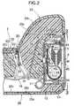
- FIG. 2is an enlarged sectional view taken along a line 2 — 2 in FIG. 1;
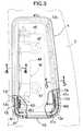
- FIG. 3is a view taken along a line 3 — 3 in FIG. 2;
- FIG. 4is an enlarged sectional view taken along a line 4 — 4 in FIG. 3;
- FIG. 5is an enlarged sectional view taken along a line 5 — 5 in FIG. 3;
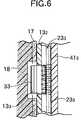
- FIG. 6is an enlarged sectional view taken along a line 6 — 6 in FIG. 2;
- FIG. 7is a view explaining the operation of the air bag device when a lid of a module case is opened.
- FIG. 8is a view explaining the operation of the air bag device when a case body of the module case is opened.
- a seat S for a driver in an automobile having right-hand driveis comprised of a seat cushion 1 disposed substantially horizontally, a seat back 2 extending rearwards and upwards from a rear end of the seat cushion 1 , and a head rest 3 mounted at upper end of the seat back 2 .
- An air bag module M accommodated in a module case 4is disposed in a right side face of the seat back 2 , and when the air bag module M is operated, an air bag 5 forces the module case 4 open to become deployed laterally and forwardly so as to intervene between a right side of an occupant sitting on the seat S and a left side of a right front door 6 (see FIG. 7 ).
- a module mounting bracket 12 made of a metal and extending forwardly in a vehicle bodyis fixed to a pipe frame 11 extending vertically along a right side edge of the seat back 2 .
- a module case mounting box 13 made of a resinis fixed to the module mounting bracket 12 , and the module case 4 having the air bag module M accommodated therein is fitted and fixed within the module case mounting box 13 .
- a spring 16is laid on an inner periphery of the pipe frame 11 , and a shape retaining member 17 made of a coarse blanket and a pad 18 made of a sponge are disposed to extend from a front surface of the spring 16 to a front surface of the module case 4 .
- a pad 19 made of a spongeis also disposed in an area surrounded by the spring 16 , the shape retaining member 17 and the module case 4 .
- a central portion of a front surface of the seat back 2is covered with a first cover member 22 , and laterally opposite sides and an upper portion of the first cover member 22 are covered with a second cover member 23 sewn at a seam 20 to the first cover member 22 , and a rear surface of the seat back 2 is covered with a third cover member 25 which covers a surface of a resinous plate 25 1 with a wadding 25 2 made of a sponge and a trim cover 25 3 made of leather or cloth.
- the first and second cover members 22 and 23have the substantially the same structure and are comprised respectively of a wadding cover 22 1 , 23 1 abutting against the pad 18 , a wadding 22 2 , 23 2 made of a thin sponge integrally coupled to a front surface of the wadding cover 22 1 , 23 1 , and a trim cover 22 3 , 23 3 made of leather or cloth superposed on a front surface of the wadding 22 2 , 23 2 .
- the winding 22 2 thereofis divided into two layers, and a single wadding cover 22 1 and a heater 26 are interposed between the two layers.
- a wire 32 made of stainless steelis accommodated within the hanging sack 30 , and a plurality of hooks 31 are locked at their one ends to the wire 32 and at the other ends to the spring 16 .
- the module case mounting box 13is a vessel-shaped member having an opened portion facing the right side of the seat back 2 , and has a flange 13 , extending outwards from the opened end thereof.
- a plurality of locking bores 13 3are defined in a front wall 13 2 of the module case mounting box 13 , and the plurality of hooks 33 provided at a rear edge of the trim cover 22 3 of the second covering member 23 are locked in the locking bore 13 3 from an inner surface of the front wall 13 2 of the module case mounting box 13 .
- the trim cover 23 3 of the second cover member 23is brought into abutment against the flange 13 1 of the module case mounting box 13 through the resinous plate 34 .
- the trim cover 25 3 of the third cover member 25is brought into abutment against the flange 13 1 of the module case mounting box 13 through the resinous plate 34 and then wound around an inner surface of a rear wall 13 4 of the module case mounting box 13 .
- Two tear lines 13 5 , 13 5are formed in lengthwise opposite ends of the inner surface of the front wall 13 2 of the module case mounting box 13 by reducing the thickness of the opposite ends so that the tear lines can be broken easily. Therefore, if a load is applied to the inner surface of the front wall 13 2 of the module case mounting box 13 , the tear lines 13 5 , 13 5 are broken, whereby the front wall 13 2 falls forwardly to form the principle or “primary” opening from the module box.
- module case 4The structure of the module case 4 will be described below with reference to FIGS. 2 to 5 .
- the resinous module case 4includes a vessel-shaped case body 41 , and a plate-shaped lid 43 which covers an opened end of the case body 41 .
- Five locking bores 41 2are defined in a rear wall 41 1 of the case body 41 , and five locking projections 43 1 integrally formed on a back of the lid 43 are engaged into the locking bores 41 2 .
- Four locking bores 41 4are also defined in a front wall 41 3 of the case body 41 , and four locking projections 43 2 integrally formed on the back of the lid 43 are engaged into the locking bores 41 4 . Therefore, the lid 43 is fixed to the case body 41 by the engagement of the locking projections 43 1 in the locking bores 41 2 and the engagement of the locking projections 43 2 in the locking bores 41 4 .
- Two tear lines 41 5 , 41 5are formed in lengthwise opposite ends of the inner surface of the front wall 41 3 of the case body 41 by reducing the thickness of the opposite ends so that the tear lines 41 5 , 41 5 can be broken easily. Therefore, if a load is applied to the inner surface of the front wall 41 3 of the case body 41 , the tear lines 41 5 , 41 5 are broken, whereby the front wall 13 2 falls forwardly to form the “primary” opening in the case body 41 .
- the air bag module M accommodated in the module case 4is comprised of an inflater 44 which is to be ignited by a signal from an acceleration sensor to generate a high-pressure gas, and the air bag 5 which expands by receiving the high-pressure gas supplied from the inflater 44 .
- Peripheral edges of two openings 41 7 , 41 7 defined in a bottom wall 41 6 of the case body 41are sandwiched between a retainer 45 retaining the inflater 44 and a stationary plate 46 , and the retainer 45 and the stationary plate 46 are fastened to each other by bolts 47 , 47 passed therethrough and by nuts 48 , 48 , whereby the air bag module M is fixed to the case body 41 .
- the lid 43 of the module case 4is substantially flush with the side face of the seat back 2 , and the peripheral edges of the second and third cover members 23 and 25 pushed against the peripheral edges of the lid 43 are fixed to the flange 13 1 of the module case mounting box 13 with the resinous plate 34 interposed therebetween.
- the inflater 44 of the air bag module Mis ignited to expand the air bag 5 by the high-pressure gas generated.
- the pressure resulting from the expansion of the air bagis applied to the inner surface of the lid 43 of the module case 4 , the locking projections 43 2 at the front edge of the lid 43 are deformed or broken to become separated from the locking bores 41 4 in the case body 41 , and the lid 43 is opened about a hinge provided by its rear edge, namely, about hinges provided by engaged portions of the locking projections 43 1 of the lid 43 and the locking bores 41 2 in the case body 41 .
- a primary opening 49is defined in a front portion of the module case 4 , so that the air bag 5 is deployed through the opening 49 to intervene between the occupant and the inner surface of the right front door 6 (see FIG. 7 ).
- the clearance between the inner surface of the right front door 6 and the lid 43 of the module case 4may be decreased, whereby the lid 43 may not be opened in some cases. Even when the lid is not opened, however, if the pressure of the expanded air bag 5 is applied to the front wall 41 3 of the case body 41 , the two tear lines 41 5 , 41 5 are broken, whereby the front wall 41 3 is turned forwardly.
- the module case mounting box 13is urged forwardly by the front wall 41 3 of the case body 41 turned forwardly, and the tear lines 13 5 , 13 5 are broken, whereby the front wall 13 2 is turned forward, while deforming the pad 18 of the seat back 2 .
- an alternate, secondary opening 50is defined in front of the case body 41 , and the air bag 5 is deployed through the secondary opening 50 along the inner surface of the right front door 6 without hindrance.
- the tear lines 41 5 , 41 5 in the case body 41have been formed in the inner surface of the front wall 41 3 in the embodiment, but tear lines 41 5 , 41 5 may be formed in an outer surface of the front wall 41 3 .
- the tear lines 41 5 , 41 5may be comprised of slits, or a large number of small bores or perforations continuously defined at small distances to make the wall of the case body frangible.
- module case 4has been mounted in the module case mounting box 13 fixed to the side face of the seat back 2 in the embodiment, but the module case 4 may be mounted directly in a recess defined in the side face of the seat back 2 .
- the lid of the module caseis opened by the pressure of the expansion of the air bag, and the air bag is normally deployed through the primary opening defined in the air bag module into the vehicle compartment.
- the tear line formed in the wall of the case bodyis broken by the pressure of expansion of the air bag to open the lid in an alternate direction different from the direction of normal, or “primary”, opening of the lid, and hence the air bag can be deployed without hindrance through the secondary opening defined by the breaking of the tear line.
Landscapes
- Engineering & Computer Science (AREA)
- Mechanical Engineering (AREA)
- Aviation & Aerospace Engineering (AREA)
- Transportation (AREA)
- Air Bags (AREA)
Abstract
Description
The present invention relates to a side-collision air bag device which is designed so that an air bag is deployed from an air bag module disposed in a side face of a seat back into a vehicle compartment to protect an occupant upon side-collision of a vehicle.
A side-collision air bag device of the concerned type is disclosed as second and third embodiments in Japanese Patent Application Laid-open No. 10-71918. This conventional device is designed so that a lid of a module case having the air bag module accommodated therein is exposed to the side face of the seat back whereby the air bag is expanded within the module case upon collision of the vehicle and forces the lid open to become deployed into the vehicle compartment.
In such conventional side-collision air bag device, there is a possibility that, when a door or a center pillar is deformed toward the inside of the vehicle compartment due to the side collision of the vehicle and is brought into contact with the side face of the seat back, the lid of the module case may be held by such an urging force and as a result, cannot be opened, whereby the smooth expansion of the air bag is impeded.
The present invention has been accomplished with the above circumstance in view, and it is an object of the present invention to ensure that, even if the door or the center pillar is deformed toward the seat back by a shock resulting from the collision, the air bag can be reliably deployed from the air bag module accommodated in the module case.
To achieve the above object, there is provided a side-collision air bag device comprising an air bag module which is accommodated in a module case including a case body and a lid and which is disposed in a side face of a seat back so that an air bag is deployed through an opening, termed the “primary opening”, defined in the lid into a vehicle compartment by opening the lid exposed to the side face of the seat back by a pressure of the air bag expanded from the air bag module. A tear line is formed in a wall of the case body and is broken by the pressure of the expanded air bag to open the wall in a direction different from a direction for opening the lid, whereby the air bag can be deployed into the vehicle compartment through a secondary opening defined in the wall.
With the above arrangement, when the air bag of the air bag module accommodated in the case body of the module case is expanded due to a side collision of the vehicle, the lid of the module case is opened by an expansion pressure, and the air bag is deployed through the primary opening defined in the case body into the vehicle compartment. If a door or a center pillar is deformed upon the collision to come close to the seat back, whereby the lid of the module case is held down so that it cannot be opened to form the primary opening, the tear line formed in the wall of the case body is broken by the pressure of expansion of the air bag to open the lid in a direction different from the direction of the primary opening formed by opening of the lid with respect to the module case and hence, the air bag can be deployed through a secondary opening defined in the case body without hindrance.
For a better understanding of the invention, its operating advantages and the specific objectives obtained by its use, reference should be made to the accompanying drawings and description which relate to a preferred embodiment thereof.
FIG. 1 is a perspective illustration of a seat provided with a side-collision air bag device according to an embodiment of the present invention;
FIG. 2 is an enlarged sectional view taken along aline 2—2 in FIG. 1;
FIG. 3 is a view taken along aline 3—3 in FIG. 2;
FIG. 4 is an enlarged sectional view taken along aline 4—4 in FIG. 3;
FIG. 5 is an enlarged sectional view taken along aline 5—5 in FIG. 3;
FIG. 6 is an enlarged sectional view taken along aline 6—6 in FIG. 2;
FIG. 7 is a view explaining the operation of the air bag device when a lid of a module case is opened; and
FIG. 8 is a view explaining the operation of the air bag device when a case body of the module case is opened.
As shown in FIG. 1, a seat S for a driver in an automobile having right-hand drive is comprised of aseat cushion 1 disposed substantially horizontally, aseat back 2 extending rearwards and upwards from a rear end of theseat cushion 1, and ahead rest 3 mounted at upper end of theseat back 2. An air bag module M accommodated in amodule case 4 is disposed in a right side face of theseat back 2, and when the air bag module M is operated, anair bag 5 forces themodule case 4 open to become deployed laterally and forwardly so as to intervene between a right side of an occupant sitting on the seat S and a left side of a right front door6 (see FIG.7).
As can be seen from a cross section of theseat back 2 shown in FIG. 2, amodule mounting bracket 12 made of a metal and extending forwardly in a vehicle body is fixed to apipe frame 11 extending vertically along a right side edge of theseat back 2. A modulecase mounting box 13 made of a resin is fixed to themodule mounting bracket 12, and themodule case 4 having the air bag module M accommodated therein is fitted and fixed within the modulecase mounting box 13. Aspring 16 is laid on an inner periphery of thepipe frame 11, and ashape retaining member 17 made of a coarse blanket and apad 18 made of a sponge are disposed to extend from a front surface of thespring 16 to a front surface of themodule case 4. Apad 19 made of a sponge is also disposed in an area surrounded by thespring 16, theshape retaining member 17 and themodule case 4.
A central portion of a front surface of theseat back 2 is covered with afirst cover member 22, and laterally opposite sides and an upper portion of thefirst cover member 22 are covered with asecond cover member 23 sewn at aseam 20 to thefirst cover member 22, and a rear surface of theseat back 2 is covered with athird cover member 25 which covers a surface of aresinous plate 251with awadding 252made of a sponge and atrim cover 253made of leather or cloth.
The first andsecond cover members wadding cover pad 18, awadding wadding cover trim cover wadding first cover member 22, the winding222thereof is divided into two layers, and asingle wadding cover 221and aheater 26 are interposed between the two layers.
A hangingsack 30 made by twice-folding a band-shaped material having a strength, such as a tricot, is integrally sewn to theseam 20 between the first andsecond cover members wire 32 made of stainless steel is accommodated within thehanging sack 30, and a plurality ofhooks 31 are locked at their one ends to thewire 32 and at the other ends to thespring 16.
As can be seen from FIGS. 2,3 and6, the modulecase mounting box 13 is a vessel-shaped member having an opened portion facing the right side of the seat back2, and has aflange 13, extending outwards from the opened end thereof. A plurality oflocking bores 133are defined in afront wall 132of the modulecase mounting box 13, and the plurality ofhooks 33 provided at a rear edge of thetrim cover 223of the second coveringmember 23 are locked in thelocking bore 133from an inner surface of thefront wall 132of the modulecase mounting box 13. At this time, thetrim cover 233of thesecond cover member 23 is brought into abutment against theflange 131of the modulecase mounting box 13 through theresinous plate 34. Thetrim cover 253of thethird cover member 25 is brought into abutment against theflange 131of the modulecase mounting box 13 through theresinous plate 34 and then wound around an inner surface of arear wall 134of the modulecase mounting box 13.
Twotear lines 135,135(see FIG. 3) are formed in lengthwise opposite ends of the inner surface of thefront wall 132of the modulecase mounting box 13 by reducing the thickness of the opposite ends so that the tear lines can be broken easily. Therefore, if a load is applied to the inner surface of thefront wall 132of the modulecase mounting box 13, thetear lines front wall 132falls forwardly to form the principle or “primary” opening from the module box.
The structure of themodule case 4 will be described below with reference to FIGS. 2 to5.
Theresinous module case 4 includes a vessel-shaped case body 41, and a plate-shaped lid 43 which covers an opened end of thecase body 41. Fivelocking bores 412are defined in arear wall 411of thecase body 41, and fivelocking projections 431integrally formed on a back of thelid 43 are engaged into thelocking bores 412. Fourlocking bores 414are also defined in afront wall 413of thecase body 41, and fourlocking projections 432integrally formed on the back of thelid 43 are engaged into thelocking bores 414. Therefore, thelid 43 is fixed to thecase body 41 by the engagement of thelocking projections 431in thelocking bores 412and the engagement of thelocking projections 432in thelocking bores 414.
Twotear lines 415,415(see FIG. 3) are formed in lengthwise opposite ends of the inner surface of thefront wall 413of thecase body 41 by reducing the thickness of the opposite ends so that thetear lines front wall 413of thecase body 41, thetear lines front wall 132falls forwardly to form the “primary” opening in thecase body 41.
The air bag module M accommodated in themodule case 4 is comprised of aninflater 44 which is to be ignited by a signal from an acceleration sensor to generate a high-pressure gas, and theair bag 5 which expands by receiving the high-pressure gas supplied from theinflater 44. Peripheral edges of twoopenings bottom wall 416of thecase body 41 are sandwiched between aretainer 45 retaining theinflater 44 and astationary plate 46, and theretainer 45 and thestationary plate 46 are fastened to each other bybolts nuts case body 41.
Thus, when themodule case 4 having the air bag module M accommodated therein is fitted and fixed in the modulecase mounting box 13 from sideways of theseat back 2, thelid 43 of themodule case 4 is substantially flush with the side face of theseat back 2, and the peripheral edges of the second andthird cover members lid 43 are fixed to theflange 131of the modulecase mounting box 13 with theresinous plate 34 interposed therebetween. By detachably mounting themodule case 4 to the side face of theseat back 2 in the above manner, it is ensured that themodule case 4 can be removed from theseat back 2 so that the maintenance of the air bag module M in themodule case 4 can be carried out easily.
The operation of the embodiment of the present invention having the above-described arrangement will be described below.
When a lateral acceleration equal to, or larger than a predetermined value upon side-collision of the vehicle has been detected, theinflater 44 of the air bag module M is ignited to expand theair bag 5 by the high-pressure gas generated. When the pressure resulting from the expansion of the air bag is applied to the inner surface of thelid 43 of themodule case 4, thelocking projections 432at the front edge of thelid 43 are deformed or broken to become separated from thelocking bores 414in thecase body 41, and thelid 43 is opened about a hinge provided by its rear edge, namely, about hinges provided by engaged portions of thelocking projections 431of thelid 43 and thelocking bores 412in thecase body 41. As a result, aprimary opening 49 is defined in a front portion of themodule case 4, so that theair bag 5 is deployed through theopening 49 to intervene between the occupant and the inner surface of the right front door6 (see FIG.7).
When theright front door 6 is deformed to come close to the seat back2 as a result of the vehicle being subjected to a rightward side collision, as shown in FIG. 8, the clearance between the inner surface of theright front door 6 and thelid 43 of themodule case 4 may be decreased, whereby thelid 43 may not be opened in some cases. Even when the lid is not opened, however, if the pressure of the expandedair bag 5 is applied to thefront wall 413of thecase body 41, the twotear lines front wall 413is turned forwardly. Then, the modulecase mounting box 13 is urged forwardly by thefront wall 413of thecase body 41 turned forwardly, and thetear lines front wall 132is turned forward, while deforming thepad 18 of the seat back2. As a result, an alternate,secondary opening 50 is defined in front of thecase body 41, and theair bag 5 is deployed through thesecondary opening 50 along the inner surface of theright front door 6 without hindrance.
For example, thetear lines case body 41 have been formed in the inner surface of thefront wall 413in the embodiment, buttear lines front wall 413. Further, thetear lines
In addition, themodule case 4 has been mounted in the modulecase mounting box 13 fixed to the side face of theseat back 2 in the embodiment, but themodule case 4 may be mounted directly in a recess defined in the side face of theseat back 2.
Consequently, as discussed above, when the air bag of the air bag module accommodated in the case body of the module case is expanded due to a side collision of the vehicle, the lid of the module case is opened by the pressure of the expansion of the air bag, and the air bag is normally deployed through the primary opening defined in the air bag module into the vehicle compartment. If the vehicle door or the center pillar thereof is deformed upon the collision to come close to the seat back, whereby the lid of the module case is held down so that it cannot be opened, the tear line formed in the wall of the case body is broken by the pressure of expansion of the air bag to open the lid in an alternate direction different from the direction of normal, or “primary”, opening of the lid, and hence the air bag can be deployed without hindrance through the secondary opening defined by the breaking of the tear line.
It will be understood that various changes in the details, materials and arrangements of parts which have been herein described and illustrated in order to explain the nature of the invention, may be made by those skilled in the art within the principle and scope of the invention as expressed in the appended claims.
Claims (4)
1. A side-collision air bag device, comprising:
an air bag module having an air bag stored in a module case which is adapted for installation in a seat in a vehicle compartment;
wherein said module case comprises:
a case body having a lid openable to define a primary opening through which said air bag is deployed from said air bag module into said vehicle compartment upon expansion of said air bag by pressurization thereof; and
a wall having a frangible portion defined by a tear line disposed in said case body other than said lid and facing in a direction different from that in which said lid faces, said tear line being broken by expansion of said air bag by pressurization thereof to define a secondary opening for deployment of said air bag into said vehicle compartment when deployment through said primary opening closed by said lid is prevented.
2. The side-collision air bag device according toclaim 1 in which said air bag module is installed in a side face of a back of said seat.
3. The side-collision air bag device according toclaim 1 in which said lid is disposed in facing relation to a side of said vehicle compartment and includes hinge means connecting said lid to said case body permitting pivotal movement of said lid with respect to said case body to form said primary opening.
4. The side-collision air bag device according toclaim 1 in which said wall containing said tear line is deformable upon breaking of said tear line by expansion of said air bag to form said secondary opening for deployment of said air bag when deployment through said primary opening closed by said lid is prevented.
Applications Claiming Priority (2)
| Application Number | Priority Date | Filing Date | Title |
|---|---|---|---|
| JP1999086913AJP3195308B6 (en) | 1999-03-29 | Side airbag device | |
| JP11-086913 | 1999-03-29 |
Publications (1)
| Publication Number | Publication Date |
|---|---|
| US6386577B1true US6386577B1 (en) | 2002-05-14 |
Family
ID=13900097
Family Applications (1)
| Application Number | Title | Priority Date | Filing Date |
|---|---|---|---|
| US09/533,972Expired - Fee RelatedUS6386577B1 (en) | 1999-03-29 | 2000-03-23 | Side-collision air bag device |
Country Status (1)
| Country | Link |
|---|---|
| US (1) | US6386577B1 (en) |
Cited By (88)
| Publication number | Priority date | Publication date | Assignee | Title |
|---|---|---|---|---|
| US20030030258A1 (en)* | 2001-08-02 | 2003-02-13 | Alban Bossenmaier | Arrangement of a vehicle seat in a vehicle and a method of making same |
| FR2850921A1 (en)* | 2003-02-06 | 2004-08-13 | Cera | Motor vehicles seat manufacturing method, involves providing cap with louver which opens under effect of pressure exerted by deployment of inflatable cushion, and mounting foam body on plate by placing cushion in rubber box |
| US20040239081A1 (en)* | 2003-04-02 | 2004-12-02 | Autoliv Development Ab | Air-bag unit mounted on a seat |
| US20050006933A1 (en)* | 2001-08-03 | 2005-01-13 | Claudio Bargheer | Safety device for a motor vehicle seat |
| DE102004040333A1 (en)* | 2004-08-17 | 2006-03-02 | Volkswagen Ag | Holding device for slip cover of backrest of car seat has rear holding latch that connects filing wire to backrest framework structure |
| US20060043712A1 (en)* | 2004-08-24 | 2006-03-02 | Sam Hakki | Collision air bag and flotation system |
| US20060113762A1 (en)* | 2004-12-01 | 2006-06-01 | Lear Corporation | Vehicle seat assembly with spaced air bag guide retainers |
| US20060113754A1 (en)* | 2004-12-01 | 2006-06-01 | Lear Corporation | Vehicle seat assembly |
| US20060113770A1 (en)* | 2004-12-01 | 2006-06-01 | Lear Corporation | Vehicle seat component side air bag module having air bag guide including flexible inner and outer panels attached by module connector and frame connector and trim cover attached by frame connector |
| US20060113764A1 (en)* | 2004-12-01 | 2006-06-01 | Lear Corporation | Vehicle seat assembly |
| US20060113772A1 (en)* | 2004-12-01 | 2006-06-01 | Lear Corporation | Vehicle seat component side air bag module having air bag guide including flexible inner and outer panels attached to a seat pad attachment wire and to the seat component frame |
| US20060113773A1 (en)* | 2004-12-01 | 2006-06-01 | Lear Corporation | Vehicle seat component side air bag module having air bag guide including flexible inner and outer panels attached to seat pad attachment wires |
| US20060113763A1 (en)* | 2004-12-01 | 2006-06-01 | Lear Corporation | Vehicle seat assembly with air bag seam opener |
| US20060113753A1 (en)* | 2004-12-01 | 2006-06-01 | Lear Corporation | Vehicle seat assembly |
| US20060113766A1 (en)* | 2004-12-01 | 2006-06-01 | Lear Corporation | Vehicle seat side air bag system |
| US20060163850A1 (en)* | 2005-01-25 | 2006-07-27 | Honda Motor Co., Ltd. | Seat for vehicle use |
| US20060279074A1 (en)* | 2005-06-13 | 2006-12-14 | Lear Corporation | Vehicle seat assembly |
| FR2887829A1 (en)* | 2005-07-01 | 2007-01-05 | Faurecia Sieges Automobile | Motor vehicle seat, has air bag module connected to frame and disposed in housing, and trapdoor, closing housing and covering module, comprising marginal fixation zone connected to frame and marginal retention zone engaged in slit |
| US20070057493A1 (en)* | 2005-09-14 | 2007-03-15 | Recaro Gmbh & Co. Kg | Vehicle seat, in particular a sports seat |
| US20070252368A1 (en)* | 2005-01-18 | 2007-11-01 | Autoliv Development Ab | Reversible Safety Padding or Plate |
| US7322597B2 (en) | 2004-12-01 | 2008-01-29 | Lear Corporation | Vehicle seat assembly with separable air bag guide retainers |
| US20080088159A1 (en)* | 2005-05-31 | 2008-04-17 | Bayerische Motoren Werke Aktiengesellschaft | Vehicle Seat Having Backrest Width Adjustment and Intergrated Seat Airbag |
| US20080203787A1 (en)* | 2005-07-22 | 2008-08-28 | Lear Corporation | Seat |
| US20080284143A1 (en)* | 2007-05-15 | 2008-11-20 | Lear Corporation | Vehicle seat having an integrated airbag module |
| US20090001783A1 (en)* | 2007-06-29 | 2009-01-01 | Toyota Motor Engineering & Manufacturing North America, Inc. | Vehicle seat having a side airbag deployment strap |
| US20090001784A1 (en)* | 2007-06-28 | 2009-01-01 | Wieczorek Joseph P | Side airbag connector assembly |
| US20090014990A1 (en)* | 2005-12-06 | 2009-01-15 | Takata-Petri Ag | Passenger restraint system |
| US20090243266A1 (en)* | 2008-03-28 | 2009-10-01 | Lear Corporation | Vehicle seat assembly with deflector inner panel air bag guide retainer |
| US20090315373A1 (en)* | 2008-06-24 | 2009-12-24 | Gm Global Technology Operations, Inc. | Vehicle Seat Side Air Bag |
| US20100156071A1 (en)* | 2008-12-18 | 2010-06-24 | Mazda Motor Corporation | Side airbag structure |
| US20110049849A1 (en)* | 2009-08-25 | 2011-03-03 | Hyundai Motor Company | Passenger seat air-bag module |
| US20110095578A1 (en)* | 2008-07-15 | 2011-04-28 | Lear Corporation | Vehicle seat assembly |
| US20110140396A1 (en)* | 2009-12-11 | 2011-06-16 | Toyota Boshoku Kabushiki Kaisha | Vehicle seat |
| US20110193327A1 (en)* | 2010-02-10 | 2011-08-11 | Lear Corporation | Vehicle seat assembly with seat pad protection member |
| US20120248745A1 (en)* | 2011-03-29 | 2012-10-04 | Kia Motors Corp. | Side airbag for vehicles |
| US20120299342A1 (en)* | 2011-05-25 | 2012-11-29 | Toyota Boshoku Kabushiki Kaisha | Vehicle seat with air bag |
| DE102011083759B3 (en)* | 2011-09-29 | 2013-02-28 | Lear Corporation | Vehicle seat assembly with rigid airbag protection element |
| DE102011116634A1 (en)* | 2011-10-20 | 2013-04-25 | Faurecia Autositze Gmbh | Backrest for vehicle seat, has side flanges with cover material whose one end is defined at attachment point that is provided at actuation units, and resilient sheet whose one end is connected with cover material at attachment point |
| US8439394B2 (en) | 2011-01-12 | 2013-05-14 | Lear Corporation | Air bag with integral protection member |
| US8573635B2 (en) | 2011-01-12 | 2013-11-05 | Lear Corporation | Vehicle seat assembly with air bag protection member |
| US20140042785A1 (en)* | 2012-08-07 | 2014-02-13 | Honda Motor Co., Ltd. | Vehicle seat device |
| EP2628634A4 (en)* | 2010-12-24 | 2014-05-07 | Honda Motor Co Ltd | VEHICLE SEAT BACKREST STRUCTURE |
| US8727374B1 (en)* | 2013-01-24 | 2014-05-20 | Ford Global Technologies, Llc | Vehicle seatback with side airbag deployment |
| US8752863B2 (en) | 2011-09-29 | 2014-06-17 | Lear Corporation | Vehicle seat assembly with air bag module having integral protection member |
| US20140291974A1 (en)* | 2013-03-28 | 2014-10-02 | Toyota Boshoku Kabushiki Kaisha | Vehicular seats |
| US8876154B2 (en) | 2012-03-30 | 2014-11-04 | Lear Corporation | Vehicle seat assembly having a back panel module |
| US8902582B2 (en) | 2012-05-22 | 2014-12-02 | Lear Corporation | Coldplate for use with a transformer in an electric vehicle (EV) or a hybrid-electric vehicle (HEV) |
| US8971038B2 (en) | 2012-05-22 | 2015-03-03 | Lear Corporation | Coldplate for use in an electric vehicle (EV) or a hybrid-electric vehicle (HEV) |
| US8971041B2 (en) | 2012-03-29 | 2015-03-03 | Lear Corporation | Coldplate for use with an inverter in an electric vehicle (EV) or a hybrid-electric vehicle (HEV) |
| US9076593B2 (en) | 2011-12-29 | 2015-07-07 | Lear Corporation | Heat conductor for use with an inverter in an electric vehicle (EV) or a hybrid-electric vehicle (HEV) |
| US20150246627A1 (en)* | 2012-10-01 | 2015-09-03 | Ts Tech Co., Ltd. | Seat backrest |
| US20150307000A1 (en)* | 2014-04-25 | 2015-10-29 | Toyota Boshoku Kabushiki Kaisha | Vehicle seat |
| US9362040B2 (en) | 2014-05-15 | 2016-06-07 | Lear Corporation | Coldplate with integrated electrical components for cooling thereof |
| DE102005057418B4 (en)* | 2004-12-01 | 2016-11-17 | Lear Corporation | Vehicle seat assembly |
| US20170015227A1 (en)* | 2015-07-13 | 2017-01-19 | Toyota Boshoku Kabushiki Kaisha | Vehicle seat |
| US9566930B2 (en) | 2015-03-02 | 2017-02-14 | Ford Global Technologies, Llc | Vehicle seat assembly with side-impact airbag deployment mechanism |
| US9615490B2 (en) | 2014-05-15 | 2017-04-04 | Lear Corporation | Coldplate with integrated DC link capacitor for cooling thereof |
| US9649962B2 (en) | 2013-01-24 | 2017-05-16 | Ford Global Technologies, Llc | Independent cushion extension and thigh support |
| US9707873B2 (en) | 2013-01-24 | 2017-07-18 | Ford Global Technologies, Llc | Flexible seatback system |
| US9707870B2 (en) | 2013-01-24 | 2017-07-18 | Ford Global Technologies, Llc | Flexible seatback system |
| US9774247B2 (en) | 2011-08-15 | 2017-09-26 | Lear Corporation | Power module cooling system |
| US20170282769A1 (en)* | 2016-04-01 | 2017-10-05 | Ford Global Technologies, Llc | Upholstered element for a vehicle seat |
| US9802512B1 (en) | 2016-04-12 | 2017-10-31 | Ford Global Technologies, Llc | Torsion spring bushing |
| US9834166B1 (en) | 2016-06-07 | 2017-12-05 | Ford Global Technologies, Llc | Side airbag energy management system |
| US9845029B1 (en) | 2016-06-06 | 2017-12-19 | Ford Global Technologies, Llc | Passive conformal seat with hybrid air/liquid cells |
| US9849856B1 (en) | 2016-06-07 | 2017-12-26 | Ford Global Technologies, Llc | Side airbag energy management system |
| US9849817B2 (en) | 2016-03-16 | 2017-12-26 | Ford Global Technologies, Llc | Composite seat structure |
| US9889773B2 (en) | 2016-04-04 | 2018-02-13 | Ford Global Technologies, Llc | Anthropomorphic upper seatback |
| US9914378B1 (en) | 2016-12-16 | 2018-03-13 | Ford Global Technologies, Llc | Decorative and functional upper seatback closeout assembly |
| US9925899B2 (en)* | 2012-11-26 | 2018-03-27 | Toyo Tire & Rubber Co., Ltd. | Seat pad |
| US9932012B1 (en)* | 2016-12-19 | 2018-04-03 | Ford Global Technologies, Llc | Inner carrier and back panel having alternating trim and side airbag attachments |
| US9994135B2 (en) | 2016-03-30 | 2018-06-12 | Ford Global Technologies, Llc | Independent cushion thigh support |
| US10046683B2 (en) | 2014-01-23 | 2018-08-14 | Ford Global Technologies, Llc | Suspension seat back and cushion system having an inner suspension panel |
| US10046682B2 (en) | 2015-08-03 | 2018-08-14 | Ford Global Technologies, Llc | Back cushion module for a vehicle seating assembly |
| US10065546B2 (en) | 2014-04-02 | 2018-09-04 | Ford Global Technologies, Llc | Vehicle seating assembly with manual independent thigh supports |
| US10166895B2 (en) | 2016-06-09 | 2019-01-01 | Ford Global Technologies, Llc | Seatback comfort carrier |
| US20190023216A1 (en)* | 2017-07-24 | 2019-01-24 | GM Global Technology Operations LLC | Seat assemblies including integrated airbag doors for motor vehicles |
| US10220737B2 (en) | 2016-04-01 | 2019-03-05 | Ford Global Technologies, Llc | Kinematic back panel |
| US10239431B2 (en) | 2016-09-02 | 2019-03-26 | Ford Global Technologies, Llc | Cross-tube attachment hook features for modular assembly and support |
| US10279714B2 (en) | 2016-08-26 | 2019-05-07 | Ford Global Technologies, Llc | Seating assembly with climate control features |
| US10286824B2 (en) | 2016-08-24 | 2019-05-14 | Ford Global Technologies, Llc | Spreader plate load distribution |
| US10286818B2 (en) | 2016-03-16 | 2019-05-14 | Ford Global Technologies, Llc | Dual suspension seating assembly |
| US10369905B2 (en) | 2014-10-03 | 2019-08-06 | Ford Global Technologies, Llc | Tuned flexible support member and flexible suspension features for comfort carriers |
| US10377279B2 (en) | 2016-06-09 | 2019-08-13 | Ford Global Technologies, Llc | Integrated decking arm support feature |
| US10391910B2 (en) | 2016-09-02 | 2019-08-27 | Ford Global Technologies, Llc | Modular assembly cross-tube attachment tab designs and functions |
| US10596936B2 (en) | 2017-05-04 | 2020-03-24 | Ford Global Technologies, Llc | Self-retaining elastic strap for vent blower attachment to a back carrier |
| US11214221B2 (en)* | 2018-08-07 | 2022-01-04 | Hyundai Mobis Co., Ltd. | Hard cover for side airbag |
| US11396249B2 (en)* | 2017-05-31 | 2022-07-26 | Kurabe Industrial Co., Ltd. | Ventilation mat |
Citations (10)
| Publication number | Priority date | Publication date | Assignee | Title |
|---|---|---|---|---|
| US5498030A (en)* | 1995-03-28 | 1996-03-12 | General Motors Corporation | Air bag module |
| US5651582A (en)* | 1994-12-20 | 1997-07-29 | Ikeda Bussan Co., Ltd. | Vehicular seat with side air-bag |
| US5676394A (en)* | 1996-09-03 | 1997-10-14 | Morton International, Inc. | Seat trim deployment cover for side airbag module |
| JPH1071918A (en) | 1997-07-08 | 1998-03-17 | Mazda Motor Corp | Energy absorbing structure for car body side part |
| US5799970A (en)* | 1996-10-01 | 1998-09-01 | Autoliv Asp, Inc. | Externally mounted side airbag module with decorative outer cover |
| US5863063A (en)* | 1997-09-23 | 1999-01-26 | Lear Corporation | Vehicle seat side airbag guide chute |
| US5890734A (en)* | 1997-03-07 | 1999-04-06 | Morton International, Inc. | Integral cover-deployment chute for side airbag module |
| US5924724A (en)* | 1996-09-27 | 1999-07-20 | Mitsubishi Jidosha Kogyo Kabushiki Kaisha | Airbag system |
| US5951039A (en)* | 1998-06-29 | 1999-09-14 | Lear Corp. | Side airbag closeout assembly for vehicular seats and method of installation |
| US5967603A (en)* | 1997-09-25 | 1999-10-19 | Johnson Controls Technology Company | Seat mounted airbag with deployment force concentrator |
- 2000
- 2000-03-23USUS09/533,972patent/US6386577B1/ennot_activeExpired - Fee Related
Patent Citations (10)
| Publication number | Priority date | Publication date | Assignee | Title |
|---|---|---|---|---|
| US5651582A (en)* | 1994-12-20 | 1997-07-29 | Ikeda Bussan Co., Ltd. | Vehicular seat with side air-bag |
| US5498030A (en)* | 1995-03-28 | 1996-03-12 | General Motors Corporation | Air bag module |
| US5676394A (en)* | 1996-09-03 | 1997-10-14 | Morton International, Inc. | Seat trim deployment cover for side airbag module |
| US5924724A (en)* | 1996-09-27 | 1999-07-20 | Mitsubishi Jidosha Kogyo Kabushiki Kaisha | Airbag system |
| US5799970A (en)* | 1996-10-01 | 1998-09-01 | Autoliv Asp, Inc. | Externally mounted side airbag module with decorative outer cover |
| US5890734A (en)* | 1997-03-07 | 1999-04-06 | Morton International, Inc. | Integral cover-deployment chute for side airbag module |
| JPH1071918A (en) | 1997-07-08 | 1998-03-17 | Mazda Motor Corp | Energy absorbing structure for car body side part |
| US5863063A (en)* | 1997-09-23 | 1999-01-26 | Lear Corporation | Vehicle seat side airbag guide chute |
| US5967603A (en)* | 1997-09-25 | 1999-10-19 | Johnson Controls Technology Company | Seat mounted airbag with deployment force concentrator |
| US5951039A (en)* | 1998-06-29 | 1999-09-14 | Lear Corp. | Side airbag closeout assembly for vehicular seats and method of installation |
Cited By (138)
| Publication number | Priority date | Publication date | Assignee | Title |
|---|---|---|---|---|
| US20030030258A1 (en)* | 2001-08-02 | 2003-02-13 | Alban Bossenmaier | Arrangement of a vehicle seat in a vehicle and a method of making same |
| US20050006933A1 (en)* | 2001-08-03 | 2005-01-13 | Claudio Bargheer | Safety device for a motor vehicle seat |
| US7100992B2 (en)* | 2001-08-03 | 2006-09-05 | Daimlerchrysler Ag | Safety device for a motor vehicle seat |
| FR2850921A1 (en)* | 2003-02-06 | 2004-08-13 | Cera | Motor vehicles seat manufacturing method, involves providing cap with louver which opens under effect of pressure exerted by deployment of inflatable cushion, and mounting foam body on plate by placing cushion in rubber box |
| EP1447284A1 (en)* | 2003-02-06 | 2004-08-18 | Centre d'Etude et de Recherche pour l'Automobile ( CERA) | Method of making a motor vehicle seat equipped with an airbag device |
| US20040239081A1 (en)* | 2003-04-02 | 2004-12-02 | Autoliv Development Ab | Air-bag unit mounted on a seat |
| US7267363B2 (en)* | 2003-04-02 | 2007-09-11 | Autoliv Development Ab | Air-bag unit mounted on a seat |
| DE102004040333A1 (en)* | 2004-08-17 | 2006-03-02 | Volkswagen Ag | Holding device for slip cover of backrest of car seat has rear holding latch that connects filing wire to backrest framework structure |
| US7882921B2 (en) | 2004-08-24 | 2011-02-08 | Sam Hakki | Collision air bag and flotation system |
| US20060043712A1 (en)* | 2004-08-24 | 2006-03-02 | Sam Hakki | Collision air bag and flotation system |
| US7232001B2 (en) | 2004-08-24 | 2007-06-19 | Sam Hakki | Collision air bag and flotation system |
| US20080309060A1 (en)* | 2004-08-24 | 2008-12-18 | Sam Hakki | Collision air bag and flotation system |
| US20060113754A1 (en)* | 2004-12-01 | 2006-06-01 | Lear Corporation | Vehicle seat assembly |
| US7195274B2 (en)* | 2004-12-01 | 2007-03-27 | Lear Corporation | Vehicle seat component side air bag module having air bag guide including flexible inner and outer panels attached by module connector and frame connector and trim cover attached by frame connector |
| US20060113753A1 (en)* | 2004-12-01 | 2006-06-01 | Lear Corporation | Vehicle seat assembly |
| US20060113766A1 (en)* | 2004-12-01 | 2006-06-01 | Lear Corporation | Vehicle seat side air bag system |
| US20060113773A1 (en)* | 2004-12-01 | 2006-06-01 | Lear Corporation | Vehicle seat component side air bag module having air bag guide including flexible inner and outer panels attached to seat pad attachment wires |
| US20060113772A1 (en)* | 2004-12-01 | 2006-06-01 | Lear Corporation | Vehicle seat component side air bag module having air bag guide including flexible inner and outer panels attached to a seat pad attachment wire and to the seat component frame |
| DE102005057497B4 (en)* | 2004-12-01 | 2012-07-26 | Lear Corp. | Side airbag system in a vehicle seat |
| US20060113764A1 (en)* | 2004-12-01 | 2006-06-01 | Lear Corporation | Vehicle seat assembly |
| US20060113770A1 (en)* | 2004-12-01 | 2006-06-01 | Lear Corporation | Vehicle seat component side air bag module having air bag guide including flexible inner and outer panels attached by module connector and frame connector and trim cover attached by frame connector |
| US20060113763A1 (en)* | 2004-12-01 | 2006-06-01 | Lear Corporation | Vehicle seat assembly with air bag seam opener |
| US7377542B2 (en)* | 2004-12-01 | 2008-05-27 | Lear Corporation | Vehicle seat side air bag system |
| US20060113762A1 (en)* | 2004-12-01 | 2006-06-01 | Lear Corporation | Vehicle seat assembly with spaced air bag guide retainers |
| DE102005057418B4 (en)* | 2004-12-01 | 2016-11-17 | Lear Corporation | Vehicle seat assembly |
| US7290792B2 (en) | 2004-12-01 | 2007-11-06 | Lear Corporation | Vehicle seat assembly |
| US7311325B2 (en)* | 2004-12-01 | 2007-12-25 | Lear Corporation | Vehicle seat assembly with air bag seam opener |
| US7322597B2 (en) | 2004-12-01 | 2008-01-29 | Lear Corporation | Vehicle seat assembly with separable air bag guide retainers |
| US7331601B2 (en)* | 2004-12-01 | 2008-02-19 | Lear Corporation | Vehicle seat component side air bag module having air bag guide including flexible inner and outer panels attached to seat pad attachment wires |
| US7334811B2 (en) | 2004-12-01 | 2008-02-26 | Lear Corporation | Vehicle seat assembly with spaced air bag guide retainers |
| US7357412B2 (en)* | 2004-12-01 | 2008-04-15 | Lear Corporation | Vehicle seat assembly |
| US7390015B2 (en)* | 2004-12-01 | 2008-06-24 | Lear Corporation | Vehicle seat component side air bag module having air bag guide including flexible inner and outer panels attached to a seat pad attachment wire and to the seat component frame |
| US20070252368A1 (en)* | 2005-01-18 | 2007-11-01 | Autoliv Development Ab | Reversible Safety Padding or Plate |
| US7726733B2 (en)* | 2005-01-18 | 2010-06-01 | Autoliv Development Ab | Reversible safety padding or plate |
| US7393005B2 (en)* | 2005-01-25 | 2008-07-01 | Honda Motor Co., Ltd. | Seat for vehicle use |
| US20060163850A1 (en)* | 2005-01-25 | 2006-07-27 | Honda Motor Co., Ltd. | Seat for vehicle use |
| US7641281B2 (en)* | 2005-05-31 | 2010-01-05 | Bayerische Motoren Werke Aktiengesellschaft | Vehicle seat having backrest width adjustment and integrated seat airbag |
| US20080088159A1 (en)* | 2005-05-31 | 2008-04-17 | Bayerische Motoren Werke Aktiengesellschaft | Vehicle Seat Having Backrest Width Adjustment and Intergrated Seat Airbag |
| US7441797B2 (en)* | 2005-06-13 | 2008-10-28 | Lear Corporation | Vehicle seat assembly |
| US20060279074A1 (en)* | 2005-06-13 | 2006-12-14 | Lear Corporation | Vehicle seat assembly |
| FR2887829A1 (en)* | 2005-07-01 | 2007-01-05 | Faurecia Sieges Automobile | Motor vehicle seat, has air bag module connected to frame and disposed in housing, and trapdoor, closing housing and covering module, comprising marginal fixation zone connected to frame and marginal retention zone engaged in slit |
| US20080203787A1 (en)* | 2005-07-22 | 2008-08-28 | Lear Corporation | Seat |
| US8075053B2 (en)* | 2005-07-22 | 2011-12-13 | Lear Corporation | Seat |
| US20070057493A1 (en)* | 2005-09-14 | 2007-03-15 | Recaro Gmbh & Co. Kg | Vehicle seat, in particular a sports seat |
| US7819423B2 (en)* | 2005-12-06 | 2010-10-26 | Takata-Petri Ag | Passenger restraint system |
| US8091920B2 (en) | 2005-12-06 | 2012-01-10 | Takata-Petri Ag | Passenger restraint system |
| US20090014990A1 (en)* | 2005-12-06 | 2009-01-15 | Takata-Petri Ag | Passenger restraint system |
| US20110012326A1 (en)* | 2005-12-06 | 2011-01-20 | Takata-Petri Ag | Passenger restraint system |
| US8256796B2 (en)* | 2005-12-06 | 2012-09-04 | Takata AG | Passenger restraint system |
| US20080284143A1 (en)* | 2007-05-15 | 2008-11-20 | Lear Corporation | Vehicle seat having an integrated airbag module |
| US8177256B2 (en) | 2007-05-15 | 2012-05-15 | Lear Corporation | Vehicle seat having an integrated airbag module |
| US20090001784A1 (en)* | 2007-06-28 | 2009-01-01 | Wieczorek Joseph P | Side airbag connector assembly |
| US7681910B2 (en) | 2007-06-28 | 2010-03-23 | Irvin Automotive Products, Inc. | Side airbag connector assembly |
| US7677594B2 (en)* | 2007-06-29 | 2010-03-16 | Toyota Motor Engineering & Manufacturing North America, Inc. | Vehicle seat having a side airbag deployment strap |
| US20090001783A1 (en)* | 2007-06-29 | 2009-01-01 | Toyota Motor Engineering & Manufacturing North America, Inc. | Vehicle seat having a side airbag deployment strap |
| US7883105B2 (en)* | 2008-03-28 | 2011-02-08 | Lear Corporation | Vehicle seat assembly with deflector inner panel air bag guide retainer |
| US20090243266A1 (en)* | 2008-03-28 | 2009-10-01 | Lear Corporation | Vehicle seat assembly with deflector inner panel air bag guide retainer |
| US20090315373A1 (en)* | 2008-06-24 | 2009-12-24 | Gm Global Technology Operations, Inc. | Vehicle Seat Side Air Bag |
| US7695064B2 (en) | 2008-06-24 | 2010-04-13 | Gm Global Technology Operations, Inc. | Vehicle seat side air bag |
| US8833852B2 (en) | 2008-07-15 | 2014-09-16 | Lear Corporation | Vehicle seat assembly |
| US20110095578A1 (en)* | 2008-07-15 | 2011-04-28 | Lear Corporation | Vehicle seat assembly |
| US20100156071A1 (en)* | 2008-12-18 | 2010-06-24 | Mazda Motor Corporation | Side airbag structure |
| US8152197B2 (en)* | 2008-12-18 | 2012-04-10 | Mazda Motor Corporation | Side airbag structure |
| US20110049849A1 (en)* | 2009-08-25 | 2011-03-03 | Hyundai Motor Company | Passenger seat air-bag module |
| US8196954B2 (en)* | 2009-08-25 | 2012-06-12 | Hyundai Motor Company | Passenger seat air-bag module |
| US20110140396A1 (en)* | 2009-12-11 | 2011-06-16 | Toyota Boshoku Kabushiki Kaisha | Vehicle seat |
| US8474858B2 (en)* | 2009-12-11 | 2013-07-02 | Toyota Boshoku Kabushiki Kaisha | Vehicle seat |
| US20110193327A1 (en)* | 2010-02-10 | 2011-08-11 | Lear Corporation | Vehicle seat assembly with seat pad protection member |
| US8672352B2 (en) | 2010-02-10 | 2014-03-18 | Lear Corporation | Vehicle seat assembly with seat pad protection member |
| US9771008B2 (en) | 2010-12-24 | 2017-09-26 | Honda Motor Co., Ltd. | Seat back structure for vehicle |
| US9056568B2 (en) | 2010-12-24 | 2015-06-16 | Honda Motor Co., Ltd. | Seat back structure for vehicle |
| EP2628634A4 (en)* | 2010-12-24 | 2014-05-07 | Honda Motor Co Ltd | VEHICLE SEAT BACKREST STRUCTURE |
| US8439394B2 (en) | 2011-01-12 | 2013-05-14 | Lear Corporation | Air bag with integral protection member |
| US8573635B2 (en) | 2011-01-12 | 2013-11-05 | Lear Corporation | Vehicle seat assembly with air bag protection member |
| US8590925B2 (en)* | 2011-03-29 | 2013-11-26 | Hyundai Motor Company | Side airbag for vehicles |
| US20120248745A1 (en)* | 2011-03-29 | 2012-10-04 | Kia Motors Corp. | Side airbag for vehicles |
| US20120299342A1 (en)* | 2011-05-25 | 2012-11-29 | Toyota Boshoku Kabushiki Kaisha | Vehicle seat with air bag |
| US8807594B2 (en)* | 2011-05-25 | 2014-08-19 | Toyota Boshoku Kabushiki Kaisha | Vehicle seat with air bag |
| US9774247B2 (en) | 2011-08-15 | 2017-09-26 | Lear Corporation | Power module cooling system |
| US8662530B2 (en) | 2011-09-29 | 2014-03-04 | Lear Corporation | Vehicle seat assembly with rigid air bag protection member |
| US8752863B2 (en) | 2011-09-29 | 2014-06-17 | Lear Corporation | Vehicle seat assembly with air bag module having integral protection member |
| DE102011083759B3 (en)* | 2011-09-29 | 2013-02-28 | Lear Corporation | Vehicle seat assembly with rigid airbag protection element |
| DE102011116634A1 (en)* | 2011-10-20 | 2013-04-25 | Faurecia Autositze Gmbh | Backrest for vehicle seat, has side flanges with cover material whose one end is defined at attachment point that is provided at actuation units, and resilient sheet whose one end is connected with cover material at attachment point |
| US9076593B2 (en) | 2011-12-29 | 2015-07-07 | Lear Corporation | Heat conductor for use with an inverter in an electric vehicle (EV) or a hybrid-electric vehicle (HEV) |
| US8971041B2 (en) | 2012-03-29 | 2015-03-03 | Lear Corporation | Coldplate for use with an inverter in an electric vehicle (EV) or a hybrid-electric vehicle (HEV) |
| US8876154B2 (en) | 2012-03-30 | 2014-11-04 | Lear Corporation | Vehicle seat assembly having a back panel module |
| US8902582B2 (en) | 2012-05-22 | 2014-12-02 | Lear Corporation | Coldplate for use with a transformer in an electric vehicle (EV) or a hybrid-electric vehicle (HEV) |
| US8971038B2 (en) | 2012-05-22 | 2015-03-03 | Lear Corporation | Coldplate for use in an electric vehicle (EV) or a hybrid-electric vehicle (HEV) |
| US9120406B2 (en)* | 2012-08-07 | 2015-09-01 | Ts Tech Co., Ltd. | Vehicle seat device |
| US20140042785A1 (en)* | 2012-08-07 | 2014-02-13 | Honda Motor Co., Ltd. | Vehicle seat device |
| US12059986B2 (en) | 2012-10-01 | 2024-08-13 | Ts Tech Co., Ltd. | Seat backrest |
| US20150246627A1 (en)* | 2012-10-01 | 2015-09-03 | Ts Tech Co., Ltd. | Seat backrest |
| US11364824B2 (en) | 2012-10-01 | 2022-06-21 | Ts Tech Co., Ltd. | Seat backrest |
| US10300816B2 (en) | 2012-10-01 | 2019-05-28 | Ts Tech Co., Ltd. | Seat backrest |
| US9694723B2 (en)* | 2012-10-01 | 2017-07-04 | Ts Tech Co., Ltd. | Seat backrest |
| US9925899B2 (en)* | 2012-11-26 | 2018-03-27 | Toyo Tire & Rubber Co., Ltd. | Seat pad |
| US9707873B2 (en) | 2013-01-24 | 2017-07-18 | Ford Global Technologies, Llc | Flexible seatback system |
| US9873360B2 (en) | 2013-01-24 | 2018-01-23 | Ford Global Technologies, Llc | Flexible seatback system |
| US9649962B2 (en) | 2013-01-24 | 2017-05-16 | Ford Global Technologies, Llc | Independent cushion extension and thigh support |
| US9873362B2 (en) | 2013-01-24 | 2018-01-23 | Ford Global Technologies, Llc | Flexible seatback system |
| US9707870B2 (en) | 2013-01-24 | 2017-07-18 | Ford Global Technologies, Llc | Flexible seatback system |
| US8727374B1 (en)* | 2013-01-24 | 2014-05-20 | Ford Global Technologies, Llc | Vehicle seatback with side airbag deployment |
| US9067559B2 (en)* | 2013-03-28 | 2015-06-30 | Toyota Boshoku Kabushiki Kaisha | Vehicular seats |
| US20140291974A1 (en)* | 2013-03-28 | 2014-10-02 | Toyota Boshoku Kabushiki Kaisha | Vehicular seats |
| US10046683B2 (en) | 2014-01-23 | 2018-08-14 | Ford Global Technologies, Llc | Suspension seat back and cushion system having an inner suspension panel |
| US10065546B2 (en) | 2014-04-02 | 2018-09-04 | Ford Global Technologies, Llc | Vehicle seating assembly with manual independent thigh supports |
| US9393893B2 (en)* | 2014-04-25 | 2016-07-19 | Toyota Boshoku Kabushiki Kaisha | Vehicle seat |
| US20150307000A1 (en)* | 2014-04-25 | 2015-10-29 | Toyota Boshoku Kabushiki Kaisha | Vehicle seat |
| US9615490B2 (en) | 2014-05-15 | 2017-04-04 | Lear Corporation | Coldplate with integrated DC link capacitor for cooling thereof |
| US9362040B2 (en) | 2014-05-15 | 2016-06-07 | Lear Corporation | Coldplate with integrated electrical components for cooling thereof |
| US10369905B2 (en) | 2014-10-03 | 2019-08-06 | Ford Global Technologies, Llc | Tuned flexible support member and flexible suspension features for comfort carriers |
| US9566930B2 (en) | 2015-03-02 | 2017-02-14 | Ford Global Technologies, Llc | Vehicle seat assembly with side-impact airbag deployment mechanism |
| US10040415B2 (en) | 2015-03-02 | 2018-08-07 | Ford Global Technologies, Llc | Vehicle seat assembly with side-impact airbag deployment mechanism |
| US9821695B2 (en)* | 2015-07-13 | 2017-11-21 | Toyota Boshoku Kabushiki Kaisha | Vehicle seat |
| US20170015227A1 (en)* | 2015-07-13 | 2017-01-19 | Toyota Boshoku Kabushiki Kaisha | Vehicle seat |
| US10046682B2 (en) | 2015-08-03 | 2018-08-14 | Ford Global Technologies, Llc | Back cushion module for a vehicle seating assembly |
| US10286818B2 (en) | 2016-03-16 | 2019-05-14 | Ford Global Technologies, Llc | Dual suspension seating assembly |
| US9849817B2 (en) | 2016-03-16 | 2017-12-26 | Ford Global Technologies, Llc | Composite seat structure |
| US9994135B2 (en) | 2016-03-30 | 2018-06-12 | Ford Global Technologies, Llc | Independent cushion thigh support |
| US20170282769A1 (en)* | 2016-04-01 | 2017-10-05 | Ford Global Technologies, Llc | Upholstered element for a vehicle seat |
| US10220737B2 (en) | 2016-04-01 | 2019-03-05 | Ford Global Technologies, Llc | Kinematic back panel |
| US9889773B2 (en) | 2016-04-04 | 2018-02-13 | Ford Global Technologies, Llc | Anthropomorphic upper seatback |
| US9802512B1 (en) | 2016-04-12 | 2017-10-31 | Ford Global Technologies, Llc | Torsion spring bushing |
| US9845029B1 (en) | 2016-06-06 | 2017-12-19 | Ford Global Technologies, Llc | Passive conformal seat with hybrid air/liquid cells |
| US9849856B1 (en) | 2016-06-07 | 2017-12-26 | Ford Global Technologies, Llc | Side airbag energy management system |
| US9834166B1 (en) | 2016-06-07 | 2017-12-05 | Ford Global Technologies, Llc | Side airbag energy management system |
| US10377279B2 (en) | 2016-06-09 | 2019-08-13 | Ford Global Technologies, Llc | Integrated decking arm support feature |
| US10166895B2 (en) | 2016-06-09 | 2019-01-01 | Ford Global Technologies, Llc | Seatback comfort carrier |
| US10286824B2 (en) | 2016-08-24 | 2019-05-14 | Ford Global Technologies, Llc | Spreader plate load distribution |
| US10279714B2 (en) | 2016-08-26 | 2019-05-07 | Ford Global Technologies, Llc | Seating assembly with climate control features |
| US10239431B2 (en) | 2016-09-02 | 2019-03-26 | Ford Global Technologies, Llc | Cross-tube attachment hook features for modular assembly and support |
| US10391910B2 (en) | 2016-09-02 | 2019-08-27 | Ford Global Technologies, Llc | Modular assembly cross-tube attachment tab designs and functions |
| US9914378B1 (en) | 2016-12-16 | 2018-03-13 | Ford Global Technologies, Llc | Decorative and functional upper seatback closeout assembly |
| US9932012B1 (en)* | 2016-12-19 | 2018-04-03 | Ford Global Technologies, Llc | Inner carrier and back panel having alternating trim and side airbag attachments |
| US10596936B2 (en) | 2017-05-04 | 2020-03-24 | Ford Global Technologies, Llc | Self-retaining elastic strap for vent blower attachment to a back carrier |
| US11396249B2 (en)* | 2017-05-31 | 2022-07-26 | Kurabe Industrial Co., Ltd. | Ventilation mat |
| US20190023216A1 (en)* | 2017-07-24 | 2019-01-24 | GM Global Technology Operations LLC | Seat assemblies including integrated airbag doors for motor vehicles |
| US11214221B2 (en)* | 2018-08-07 | 2022-01-04 | Hyundai Mobis Co., Ltd. | Hard cover for side airbag |
Also Published As
| Publication number | Publication date |
|---|---|
| JP2000280851A (en) | 2000-10-10 |
| JP3195308B2 (en) | 2001-08-06 |
Similar Documents
| Publication | Publication Date | Title |
|---|---|---|
| US6386577B1 (en) | Side-collision air bag device | |
| US5988674A (en) | Air bag apparatus | |
| EP0669230B1 (en) | Multi-directional air bag module door attachment | |
| US4925209A (en) | Assembly for mounting air bag cover | |
| US5564739A (en) | Side impact airbag module with soft cover | |
| EP0646501B1 (en) | Invisible seam deployment door installation with stabilized air bag deployment opening construction | |
| US5344182A (en) | Air bag retention in inflatable restraint systems | |
| US3904222A (en) | Occupant restraint system | |
| EP1780074B1 (en) | Passenger constraining apparatus | |
| US5676394A (en) | Seat trim deployment cover for side airbag module | |
| US6322101B1 (en) | Instrument panel integrally equipped with air bag door portion | |
| JPH08225057A (en) | Air bag installation for front passenger seat or rear seat | |
| US5876060A (en) | Seat mounted side impact module | |
| JPH0455149A (en) | Air bag device for assistant driver's seat | |
| JPH05319197A (en) | Air bag device for front passenger's seat | |
| EP0953482B1 (en) | Airbag device for driver | |
| JPH10157549A (en) | Airbag device for vehicle seat | |
| US5505484A (en) | Collapsible airbag canister | |
| KR100260874B1 (en) | Air bag module cover | |
| JP3330032B2 (en) | Airbag device | |
| JP3406164B2 (en) | Airbag device | |
| JP4379287B2 (en) | Cover body of airbag device | |
| JP3180475B2 (en) | Airbag door structure | |
| JP3488943B2 (en) | Side airbag device for vehicle seats | |
| JP3195308B6 (en) | Side airbag device |
Legal Events
| Date | Code | Title | Description |
|---|---|---|---|
| AS | Assignment | Owner name:HONDA GIKEN KOGYO KABUSHIKI KAISHA, JAPAN Free format text:ASSIGNMENT OF ASSIGNORS INTEREST;ASSIGNORS:KAN, MAKOTO;HONDA, TAKASHI;TAKEMURA, NAOTOSHI;AND OTHERS;REEL/FRAME:010642/0530 Effective date:20000310 | |
| FPAY | Fee payment | Year of fee payment:4 | |
| REMI | Maintenance fee reminder mailed | ||
| LAPS | Lapse for failure to pay maintenance fees | ||
| STCH | Information on status: patent discontinuation | Free format text:PATENT EXPIRED DUE TO NONPAYMENT OF MAINTENANCE FEES UNDER 37 CFR 1.362 | |
| FP | Expired due to failure to pay maintenance fee | Effective date:20100514 |