US6385981B1 - Capacity control of refrigeration systems - Google Patents
Capacity control of refrigeration systemsDownload PDFInfo
- Publication number
- US6385981B1 US6385981B1US09/882,074US88207401AUS6385981B1US 6385981 B1US6385981 B1US 6385981B1US 88207401 AUS88207401 AUS 88207401AUS 6385981 B1US6385981 B1US 6385981B1
- Authority
- US
- United States
- Prior art keywords
- refrigeration system
- recited
- valve
- variable flow
- economizer
- Prior art date
- Legal status (The legal status is an assumption and is not a legal conclusion. Google has not performed a legal analysis and makes no representation as to the accuracy of the status listed.)
- Expired - Fee Related
Links
- 238000005057refrigerationMethods0.000titleclaimsabstractdescription48
- 238000007906compressionMethods0.000claimsabstractdescription21
- 230000006835compressionEffects0.000claimsabstractdescription20
- 239000003507refrigerantSubstances0.000claimsdescription18
- 238000004891communicationMethods0.000claimsdescription4
- 238000001704evaporationMethods0.000claimsdescription3
- 238000000034methodMethods0.000abstractdescription5
- 238000001816coolingMethods0.000abstractdescription3
- 230000001172regenerating effectEffects0.000description7
- 239000007788liquidSubstances0.000description6
- 239000012530fluidSubstances0.000description5
- 239000000203mixtureSubstances0.000description4
- 230000003247decreasing effectEffects0.000description3
- CURLTUGMZLYLDI-UHFFFAOYSA-NCarbon dioxideChemical compoundO=C=OCURLTUGMZLYLDI-UHFFFAOYSA-N0.000description2
- 238000013461designMethods0.000description2
- 238000002347injectionMethods0.000description2
- 239000007924injectionSubstances0.000description2
- 239000007791liquid phaseSubstances0.000description2
- 229910002092carbon dioxideInorganic materials0.000description1
- 239000001569carbon dioxideSubstances0.000description1
- 230000005494condensationEffects0.000description1
- 238000009833condensationMethods0.000description1
- 238000010276constructionMethods0.000description1
- 230000001276controlling effectEffects0.000description1
- 230000001351cycling effectEffects0.000description1
- 238000011161developmentMethods0.000description1
- 238000010586diagramMethods0.000description1
- 230000000694effectsEffects0.000description1
- 230000003116impacting effectEffects0.000description1
- 238000012986modificationMethods0.000description1
- 230000004048modificationEffects0.000description1
- 230000001105regulatory effectEffects0.000description1
Images
Classifications
- F—MECHANICAL ENGINEERING; LIGHTING; HEATING; WEAPONS; BLASTING
- F25—REFRIGERATION OR COOLING; COMBINED HEATING AND REFRIGERATION SYSTEMS; HEAT PUMP SYSTEMS; MANUFACTURE OR STORAGE OF ICE; LIQUEFACTION SOLIDIFICATION OF GASES
- F25B—REFRIGERATION MACHINES, PLANTS OR SYSTEMS; COMBINED HEATING AND REFRIGERATION SYSTEMS; HEAT PUMP SYSTEMS
- F25B49/00—Arrangement or mounting of control or safety devices
- F25B49/02—Arrangement or mounting of control or safety devices for compression type machines, plants or systems
- F25B49/022—Compressor control arrangements
- F—MECHANICAL ENGINEERING; LIGHTING; HEATING; WEAPONS; BLASTING
- F04—POSITIVE - DISPLACEMENT MACHINES FOR LIQUIDS; PUMPS FOR LIQUIDS OR ELASTIC FLUIDS
- F04C—ROTARY-PISTON, OR OSCILLATING-PISTON, POSITIVE-DISPLACEMENT MACHINES FOR LIQUIDS; ROTARY-PISTON, OR OSCILLATING-PISTON, POSITIVE-DISPLACEMENT PUMPS
- F04C29/00—Component parts, details or accessories of pumps or pumping installations, not provided for in groups F04C18/00 - F04C28/00
- F04C29/0007—Injection of a fluid in the working chamber for sealing, cooling and lubricating
- F04C29/0014—Injection of a fluid in the working chamber for sealing, cooling and lubricating with control systems for the injection of the fluid
- F—MECHANICAL ENGINEERING; LIGHTING; HEATING; WEAPONS; BLASTING
- F04—POSITIVE - DISPLACEMENT MACHINES FOR LIQUIDS; PUMPS FOR LIQUIDS OR ELASTIC FLUIDS
- F04C—ROTARY-PISTON, OR OSCILLATING-PISTON, POSITIVE-DISPLACEMENT MACHINES FOR LIQUIDS; ROTARY-PISTON, OR OSCILLATING-PISTON, POSITIVE-DISPLACEMENT PUMPS
- F04C18/00—Rotary-piston pumps specially adapted for elastic fluids
- F04C18/30—Rotary-piston pumps specially adapted for elastic fluids having the characteristics covered by two or more of groups F04C18/02, F04C18/08, F04C18/22, F04C18/24, F04C18/48, or having the characteristics covered by one of these groups together with some other type of movement between co-operating members
- F04C18/34—Rotary-piston pumps specially adapted for elastic fluids having the characteristics covered by two or more of groups F04C18/02, F04C18/08, F04C18/22, F04C18/24, F04C18/48, or having the characteristics covered by one of these groups together with some other type of movement between co-operating members having the movement defined in group F04C18/08 or F04C18/22 and relative reciprocation between the co-operating members
- F04C18/344—Rotary-piston pumps specially adapted for elastic fluids having the characteristics covered by two or more of groups F04C18/02, F04C18/08, F04C18/22, F04C18/24, F04C18/48, or having the characteristics covered by one of these groups together with some other type of movement between co-operating members having the movement defined in group F04C18/08 or F04C18/22 and relative reciprocation between the co-operating members with vanes reciprocating with respect to the inner member
- F04C18/3441—Rotary-piston pumps specially adapted for elastic fluids having the characteristics covered by two or more of groups F04C18/02, F04C18/08, F04C18/22, F04C18/24, F04C18/48, or having the characteristics covered by one of these groups together with some other type of movement between co-operating members having the movement defined in group F04C18/08 or F04C18/22 and relative reciprocation between the co-operating members with vanes reciprocating with respect to the inner member the inner and outer member being in contact along one line or continuous surface substantially parallel to the axis of rotation
- F—MECHANICAL ENGINEERING; LIGHTING; HEATING; WEAPONS; BLASTING
- F25—REFRIGERATION OR COOLING; COMBINED HEATING AND REFRIGERATION SYSTEMS; HEAT PUMP SYSTEMS; MANUFACTURE OR STORAGE OF ICE; LIQUEFACTION SOLIDIFICATION OF GASES
- F25B—REFRIGERATION MACHINES, PLANTS OR SYSTEMS; COMBINED HEATING AND REFRIGERATION SYSTEMS; HEAT PUMP SYSTEMS
- F25B2309/00—Gas cycle refrigeration machines
- F25B2309/06—Compression machines, plants or systems characterised by the refrigerant being carbon dioxide
- F25B2309/061—Compression machines, plants or systems characterised by the refrigerant being carbon dioxide with cycle highest pressure above the supercritical pressure
- F—MECHANICAL ENGINEERING; LIGHTING; HEATING; WEAPONS; BLASTING
- F25—REFRIGERATION OR COOLING; COMBINED HEATING AND REFRIGERATION SYSTEMS; HEAT PUMP SYSTEMS; MANUFACTURE OR STORAGE OF ICE; LIQUEFACTION SOLIDIFICATION OF GASES
- F25B—REFRIGERATION MACHINES, PLANTS OR SYSTEMS; COMBINED HEATING AND REFRIGERATION SYSTEMS; HEAT PUMP SYSTEMS
- F25B2400/00—General features or devices for refrigeration machines, plants or systems, combined heating and refrigeration systems or heat-pump systems, i.e. not limited to a particular subgroup of F25B
- F25B2400/13—Economisers
- F—MECHANICAL ENGINEERING; LIGHTING; HEATING; WEAPONS; BLASTING
- F25—REFRIGERATION OR COOLING; COMBINED HEATING AND REFRIGERATION SYSTEMS; HEAT PUMP SYSTEMS; MANUFACTURE OR STORAGE OF ICE; LIQUEFACTION SOLIDIFICATION OF GASES
- F25B—REFRIGERATION MACHINES, PLANTS OR SYSTEMS; COMBINED HEATING AND REFRIGERATION SYSTEMS; HEAT PUMP SYSTEMS
- F25B2600/00—Control issues
- F25B2600/25—Control of valves
- F25B2600/2509—Economiser valves
- F—MECHANICAL ENGINEERING; LIGHTING; HEATING; WEAPONS; BLASTING
- F25—REFRIGERATION OR COOLING; COMBINED HEATING AND REFRIGERATION SYSTEMS; HEAT PUMP SYSTEMS; MANUFACTURE OR STORAGE OF ICE; LIQUEFACTION SOLIDIFICATION OF GASES
- F25B—REFRIGERATION MACHINES, PLANTS OR SYSTEMS; COMBINED HEATING AND REFRIGERATION SYSTEMS; HEAT PUMP SYSTEMS
- F25B41/00—Fluid-circulation arrangements
- F25B41/20—Disposition of valves, e.g. of on-off valves or flow control valves
- F25B41/22—Disposition of valves, e.g. of on-off valves or flow control valves between evaporator and compressor
- F—MECHANICAL ENGINEERING; LIGHTING; HEATING; WEAPONS; BLASTING
- F25—REFRIGERATION OR COOLING; COMBINED HEATING AND REFRIGERATION SYSTEMS; HEAT PUMP SYSTEMS; MANUFACTURE OR STORAGE OF ICE; LIQUEFACTION SOLIDIFICATION OF GASES
- F25B—REFRIGERATION MACHINES, PLANTS OR SYSTEMS; COMBINED HEATING AND REFRIGERATION SYSTEMS; HEAT PUMP SYSTEMS
- F25B9/00—Compression machines, plants or systems, in which the refrigerant is air or other gas of low boiling point
- F25B9/002—Compression machines, plants or systems, in which the refrigerant is air or other gas of low boiling point characterised by the refrigerant
- F25B9/008—Compression machines, plants or systems, in which the refrigerant is air or other gas of low boiling point characterised by the refrigerant the refrigerant being carbon dioxide
Definitions
- the inventionrelates to refrigeration systems using unloading rotary compressors.
- the main problem of controlling compression system capacityis to reduce both the capacity of the compressor and the power required to drive the compressor rotor to the same extent.
- One commonly utilized means of achieving a capacity reductionis to bypass a portion of the fluid from the discharge side of the compressor back to the suction side.
- This methodrequires an auxiliary pipe connecting the discharge and suction sides of the compressor with a valve located in the pipe. Such an arrangement reduces the system capacity since a smaller amount of fluid is directed to the main system circuit, but it does not reduce the power consumption since the compressor pumps the same amount of fluid.
- the systemis provided with an unloader valve which selectively communicates the economizer injection line back to suction.
- the fluid ports and passages necessary to achieve the economizer injectionare also utilized to achieve suction bypass unloading, and thus the compressor and system design and construction are simplified.
- the compressor chambercommunicates with the additional volume of the passages, thus impacting compressor efficiency. If the passages are made too small to reduce the impact on compressor efficiency, unloading capacity would not be enough.
- a pulsed flow capacity controlis achieved by rapidly cycling solenoid valves in the suction line, the economizer circuit, and in a bypass line with the percent of “open” time for the valve regulating the rate of flow.
- the provision of three modulating valvesresults in an increased complexity and a reduced reliability of the whole refrigeration system.
- the present inventionis directed to a method of reducing cooling capacity in a refrigeration system with a rotary compressor in such a way that the power requirement to drive the rotor is reduced to the same extent (or close to) as capacity is reduced. In an aspect of the invention this is accomplished without any impact on compressor efficiency at regular mode. In another aspect, this is accomplished without excessive complexity or low reliability.
- the present inventionprovides a refrigeration system comprising a main circuit, and a bypass circuit.
- the main circuitcomprises, in a closed loop, a compressor, a condenser unit, an expansion device, an evaporator unit, connecting piping and appropriate refrigeration control.
- the compressorincludes a housing, an inlet, an outlet, a compression region therebetween, an economizer port located in the compression region at a point where the port is in communication with the compression chamber after it has been closed for compression, and a variable flow valve associated with the economizer port.
- a body of the valveis a part of a body of the housing and a seat of the valve in a closed position is shaped to be contiguous with internal portion of the housing.
- the bypass circuithas a second solenoid valve located between the economizer port and the suction side of the compressor.
- the variable flow valve, a control system, and a transducer, reading parameters associated with a system capacity demand,are wired in an electrical circuit.
- the control systemactivates the valves based on the capacity demand.
- a refrigeration systemcomprising a main circuit, and an economizer circuit.
- the main circuitcomprises, in a closed loop, a compressor, a condenser unit, an expansion device, an evaporator unit, connecting piping and appropriate refrigeration control.
- the compressorincludes a housing, an inlet, an outlet, a compression region therebetween, an economizer port located in the compression region at a point where the port is in communication with the compression chamber after it has been closed for compression, and a variable flow valve associated with the economizer port.
- a body of the valveis a part of a body of the housing and a seat of the valve in a closed position is shaped to be contiguous with internal portion of the housing.
- the economizer circuitincludes a first solenoid valve, an additional expansion device and an economizing heat exchanger and is connected to the economizer port.
- the economizing heat exchangerprovides thermal contact between refrigerant in the main circuit after the condenser unit and evaporating refrigerant in the economizer circuit after the additional expansion device.
- the variable flow valve, a control system, and a transducer, reading parameters associated with a system capacity demand,are wired in an electrical circuit. The control system activates the valves based on the capacity demand.
- the refrigeration systemWhen the economizer and bypass circuits are applied together the refrigeration system includes a first solenoid valve in the bypass circuit and a second solenoid valve in the economizer circuit.
- the refrigeration systemhas an advantage in terms of the system simplicity and reliability since only one variable flow valve is required.
- the FIGUREis a schematic diagram of a Refrigeration System utilizing capacity control.
- a refrigeration systemrealizing abilities to increase and decrease capacity, consists of three circuits: a main circuit, an economizer circuit for the increased capacity mode, and a bypass circuit for the decreased capacity mode.
- the main circuitincludes a compressor 1 , a condenser 2 , a high pressure side 3 of a regenerative heat exchanger 4 , an expansion valve 5 , and an evaporator 6 .
- the compressor 1has the economizer port 7 , the variable flow (including a solenoid type) valve 8 , and the outlet 9 .
- a seat of the valve 8 in a closed positionis shaped to be contiguous with the wall portion of the compression chamber.
- the compressorcould be provided with a plurality of the economizer ports and seats providing contiguous shape of seats providing contiguous shape of seats in respect to the wall portion of the compression chamber.
- the economizer circuitincludes a solenoid valve 10 , an auxiliary expansion valve 11 , and a low pressure side 12 of the regenerative heat exchanger 4 .
- the bypass circuitincludes a solenoid valve 13 .
- Both economizer and bypass loopscommunicate with the economizer port 7 over the valve 8 and outlet 9 at one end.
- the economizer circuit at the other endis connected either to an outlet 14 of the high pressure side 3 of the regenerative heat exchanger 4 or, as an option, to an inlet 15 of the high pressure side 3 of the regenerative heat exchanger 4 .
- the bypass loop circuit at the other endis connected to the compressor suction line.
- valves 8 , 10 and 14are closed and the refrigeration system operates as follows.
- the compressor 1induces vapor at low pressure from the evaporator 6 , compresses it to high pressure, and discharges the compressed vapor into condenser 2 .
- condenser vaporIn the condenser vapor is liquefied.
- Liquid refrigerant after the condenser 2passes the high pressure side 3 of the regenerative heat exchanger 4 , expands in the expansion valve 5 from high pressure to low pressure turning the liquid into a mixture of vapor and liquid, and enters the evaporator 6 .
- the liquid phase of the mixtureis boiled out, absorbing heat from objects to be cooled. Vapor, appearing at the evaporator outlet, is induced by the compressor and the thermodynamic cycle is reproduced.
- valves 8 and 10are opened and the valve 13 is closed.
- a part of refrigerant flow at the outlet 14 (or at the inlet 15 as shown with a dashed line) of the regenerative heat exchanger 4is expanded in the expansion valve 11 from high pressure to low pressure turning the liquid to a mixture of vapor and liquid. Then the mixture enters the low pressure side 12 of the regenerative heat exchanger 4 .
- the liquid phaseis boiled out, subcooling liquid refrigerant flow in the high pressure side 3 . Vapor, appearing at the heat exchanger outlet 14 , is introduced into compression process over the economizer port 7 without any effect on refrigerant flow induced by the compressor 1 from the suction line. This additional subcooling increases total cooling capacity.
- valve 8is a solenoid one
- the systemgenerates two levels of system capacity: a nominal capacity, when the valve is closed, and a maximal capacity, when the valve is opened.
- valve 8is a control valve
- the systemgenerates any intermediate capacity from the nominal one, when the valve is completely closed, to the maximal one, when the valve is completely opened.
- the intermediate capacity between the nominal and maximal onesis provided at intermediate positions of the valve seat depending on the capacity demand.
- valve 8is a pulsing one
- the systemgenerates any intermediate capacity from the nominal one, when the valve is closed for the full pulsing cycle, to the maximal one, when the valve is opened for the full pulsing cycle.
- the intermediate capacity between the nominal and maximal onesis provided by the relation between the time or portion of the pulsing cycle when the valve seat is at an opened position, to the time or portion of the pulsing cycle when the valve seat is at a closed position, depending on the capacity demand.
- valve 10In the decreased capacity mode the valve 10 is closed and the valves 8 and 13 are opened. In this mode a part of the refrigerant flow from the economizer port 7 is returned back to the suction line, decreasing the amount of refrigerant circulating over the main circuit.
- valve 8is a solenoid one
- the systemgenerates two levels of system capacity: a nominal capacity, when the valve is closed, and a minimal capacity, when the valve is opened.
- valve 8is a control valve
- the systemgenerates any intermediate capacity from the nominal one, when the valve is closed, to the minimal one, when the valve is opened.
- the intermediate capacity between the nominal and maximal onesis provided at intermediate positions of the valve seat depending on the capacity demand.
- valve 8is a pulsing one
- the systemgenerates any intermediate capacity from the nominal one, when the valve is closed for the full pulsing cycle, to the minimal one, when the valve is opened for the full pulsing cycle.
- the intermediate capacity between the nominal and maximal onesis provided by the relation between the time or portion of the pulsing cycle when the valve seat is at an opened position, to the time or portion of the pulsing cycle when the valve seat is at a closed position, depending on the capacity demand.
- a transcritical refrigerantsuch as carbon dioxide
- a gas cooleris applied since instead of the condensation process the transcritical heat rejection process takes place.
- the refrigeration system described abovehas only one variable flow valve, which is an advantage in terms of the system simplicity and reliability.
Landscapes
- Engineering & Computer Science (AREA)
- Mechanical Engineering (AREA)
- General Engineering & Computer Science (AREA)
- Physics & Mathematics (AREA)
- Thermal Sciences (AREA)
- Applications Or Details Of Rotary Compressors (AREA)
Abstract
Description
This application is a continuation-in-part of the patent application “Capacity Control of Compressors” Ser. No. 09/526,453 dated Mar. 16, 2000.
The invention relates to refrigeration systems using unloading rotary compressors.
The main problem of controlling compression system capacity is to reduce both the capacity of the compressor and the power required to drive the compressor rotor to the same extent.
One commonly utilized means of achieving a capacity reduction is to bypass a portion of the fluid from the discharge side of the compressor back to the suction side. This method requires an auxiliary pipe connecting the discharge and suction sides of the compressor with a valve located in the pipe. Such an arrangement reduces the system capacity since a smaller amount of fluid is directed to the main system circuit, but it does not reduce the power consumption since the compressor pumps the same amount of fluid.
On the other hand, in many refrigeration or refrigerant compression applications, there are other times when it would be more desirable to have the ability to also achieve increased capacity. One way of achieving increased capacity is the inclusion of an economizer circuit into the refrigerant system. Typically, the economizer fluid is injected through an economizer port at a point after the compression chambers have been closed.
In one design, the system is provided with an unloader valve which selectively communicates the economizer injection line back to suction. In this arrangement, the fluid ports and passages necessary to achieve the economizer injection are also utilized to achieve suction bypass unloading, and thus the compressor and system design and construction are simplified. However, operating in regular mode, the compressor chamber communicates with the additional volume of the passages, thus impacting compressor efficiency. If the passages are made too small to reduce the impact on compressor efficiency, unloading capacity would not be enough.
As a further development a pulsed flow capacity control is achieved by rapidly cycling solenoid valves in the suction line, the economizer circuit, and in a bypass line with the percent of “open” time for the valve regulating the rate of flow. The provision of three modulating valves results in an increased complexity and a reduced reliability of the whole refrigeration system.
The present invention is directed to a method of reducing cooling capacity in a refrigeration system with a rotary compressor in such a way that the power requirement to drive the rotor is reduced to the same extent (or close to) as capacity is reduced. In an aspect of the invention this is accomplished without any impact on compressor efficiency at regular mode. In another aspect, this is accomplished without excessive complexity or low reliability.
The present invention provides a refrigeration system comprising a main circuit, and a bypass circuit. The main circuit comprises, in a closed loop, a compressor, a condenser unit, an expansion device, an evaporator unit, connecting piping and appropriate refrigeration control. The compressor includes a housing, an inlet, an outlet, a compression region therebetween, an economizer port located in the compression region at a point where the port is in communication with the compression chamber after it has been closed for compression, and a variable flow valve associated with the economizer port. A body of the valve is a part of a body of the housing and a seat of the valve in a closed position is shaped to be contiguous with internal portion of the housing. The bypass circuit has a second solenoid valve located between the economizer port and the suction side of the compressor. The variable flow valve, a control system, and a transducer, reading parameters associated with a system capacity demand, are wired in an electrical circuit. The control system activates the valves based on the capacity demand.
One more aspect of the invention there is provided a refrigeration system comprising a main circuit, and an economizer circuit. The main circuit comprises, in a closed loop, a compressor, a condenser unit, an expansion device, an evaporator unit, connecting piping and appropriate refrigeration control. The compressor includes a housing, an inlet, an outlet, a compression region therebetween, an economizer port located in the compression region at a point where the port is in communication with the compression chamber after it has been closed for compression, and a variable flow valve associated with the economizer port. A body of the valve is a part of a body of the housing and a seat of the valve in a closed position is shaped to be contiguous with internal portion of the housing. The economizer circuit includes a first solenoid valve, an additional expansion device and an economizing heat exchanger and is connected to the economizer port. The economizing heat exchanger provides thermal contact between refrigerant in the main circuit after the condenser unit and evaporating refrigerant in the economizer circuit after the additional expansion device. The variable flow valve, a control system, and a transducer, reading parameters associated with a system capacity demand, are wired in an electrical circuit. The control system activates the valves based on the capacity demand.
When the economizer and bypass circuits are applied together the refrigeration system includes a first solenoid valve in the bypass circuit and a second solenoid valve in the economizer circuit.
According to the invention the refrigeration system has an advantage in terms of the system simplicity and reliability since only one variable flow valve is required.
Preferred embodiments of the present invention are illustrated in the attached drawing, which is:
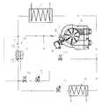
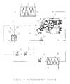
The FIGURE is a schematic diagram of a Refrigeration System utilizing capacity control.
A refrigeration system, realizing abilities to increase and decrease capacity, consists of three circuits: a main circuit, an economizer circuit for the increased capacity mode, and a bypass circuit for the decreased capacity mode.
The main circuit includes acompressor 1, acondenser 2, ahigh pressure side 3 of aregenerative heat exchanger 4, anexpansion valve 5, and anevaporator 6. Thecompressor 1 has theeconomizer port 7, the variable flow (including a solenoid type)valve 8, and theoutlet 9. A seat of thevalve 8 in a closed position is shaped to be contiguous with the wall portion of the compression chamber.
The compressor could be provided with a plurality of the economizer ports and seats providing contiguous shape of seats providing contiguous shape of seats in respect to the wall portion of the compression chamber.
The economizer circuit includes asolenoid valve 10, anauxiliary expansion valve 11, and alow pressure side 12 of theregenerative heat exchanger 4.
The bypass circuit includes asolenoid valve 13.
Both economizer and bypass loops, communicate with theeconomizer port 7 over thevalve 8 andoutlet 9 at one end. The economizer circuit at the other end is connected either to anoutlet 14 of thehigh pressure side 3 of theregenerative heat exchanger 4 or, as an option, to aninlet 15 of thehigh pressure side 3 of theregenerative heat exchanger 4. The bypass loop circuit at the other end is connected to the compressor suction line.
In the regular mode thevalves compressor 1 induces vapor at low pressure from theevaporator 6, compresses it to high pressure, and discharges the compressed vapor intocondenser 2. In the condenser vapor is liquefied. Liquid refrigerant after thecondenser 2 passes thehigh pressure side 3 of theregenerative heat exchanger 4, expands in theexpansion valve 5 from high pressure to low pressure turning the liquid into a mixture of vapor and liquid, and enters theevaporator 6. In theevaporator 6, the liquid phase of the mixture is boiled out, absorbing heat from objects to be cooled. Vapor, appearing at the evaporator outlet, is induced by the compressor and the thermodynamic cycle is reproduced.
In the increased capacity mode, thevalves valve 13 is closed. In this mode a part of refrigerant flow at the outlet14 (or at theinlet 15 as shown with a dashed line) of theregenerative heat exchanger 4 is expanded in theexpansion valve 11 from high pressure to low pressure turning the liquid to a mixture of vapor and liquid. Then the mixture enters thelow pressure side 12 of theregenerative heat exchanger 4. In theheat exchanger 4 the liquid phase is boiled out, subcooling liquid refrigerant flow in thehigh pressure side 3. Vapor, appearing at theheat exchanger outlet 14, is introduced into compression process over theeconomizer port 7 without any effect on refrigerant flow induced by thecompressor 1 from the suction line. This additional subcooling increases total cooling capacity.
If thevalve 8 is a solenoid one, then the system generates two levels of system capacity: a nominal capacity, when the valve is closed, and a maximal capacity, when the valve is opened.
If thevalve 8 is a control valve, then the system generates any intermediate capacity from the nominal one, when the valve is completely closed, to the maximal one, when the valve is completely opened. The intermediate capacity between the nominal and maximal ones is provided at intermediate positions of the valve seat depending on the capacity demand.
If thevalve 8 is a pulsing one, then the system generates any intermediate capacity from the nominal one, when the valve is closed for the full pulsing cycle, to the maximal one, when the valve is opened for the full pulsing cycle. The intermediate capacity between the nominal and maximal ones is provided by the relation between the time or portion of the pulsing cycle when the valve seat is at an opened position, to the time or portion of the pulsing cycle when the valve seat is at a closed position, depending on the capacity demand.
In the decreased capacity mode thevalve 10 is closed and thevalves economizer port 7 is returned back to the suction line, decreasing the amount of refrigerant circulating over the main circuit.
If thevalve 8 is a solenoid one, then the system generates two levels of system capacity: a nominal capacity, when the valve is closed, and a minimal capacity, when the valve is opened.
If thevalve 8 is a control valve, then the system generates any intermediate capacity from the nominal one, when the valve is closed, to the minimal one, when the valve is opened. The intermediate capacity between the nominal and maximal ones is provided at intermediate positions of the valve seat depending on the capacity demand.
If thevalve 8 is a pulsing one, then the system generates any intermediate capacity from the nominal one, when the valve is closed for the full pulsing cycle, to the minimal one, when the valve is opened for the full pulsing cycle. The intermediate capacity between the nominal and maximal ones is provided by the relation between the time or portion of the pulsing cycle when the valve seat is at an opened position, to the time or portion of the pulsing cycle when the valve seat is at a closed position, depending on the capacity demand.
If a transcritical refrigerant (such as carbon dioxide) is applied, than instead of thecondenser 2, a gas cooler is applied since instead of the condensation process the transcritical heat rejection process takes place.
The refrigeration system described above has only one variable flow valve, which is an advantage in terms of the system simplicity and reliability.
While certain preferred embodiments of the present invention have been disclosed in detail, it is to be understood that various modifications in its structure may be adopted without departing from the spirit of the invention or the scope of the following claims
Claims (27)
1. A refrigeration system comprising:
(a) a compressor unit including a housing, a suction side and a discharge side, an economizer port located at a point after the compression chambers have been closed for compression; a variable flow valve associated with said economizer port, which in an opened position provides communication between said compression chamber and an external outlet of said economizer port over said economizer port; a body of said valve being a part of a body of said housing and a seat of said valve in a closed position is shaped to be contiguous with internal portion of said housing;
(b) a closed main circuit including said compressor, a condenser unit, an expansion device, an evaporator unit, connecting piping and appropriate refrigeration control;
(c) a bypass circuit between said external outlet and said suction side; and
(d) an electrical circuit including said variable flow valve, a control system, and a transducer reading parameters associated with a system capacity demand.
2. A refrigeration system as recited inclaim 1 wherein said compressor unit is a rotary vane compressor unit.
3. A refrigeration system as recited inclaim 1 wherein said condenser unit is a gas cooler unit providing transcritical heat rejection.
4. A refrigeration system as recited inclaim 1 wherein said port and said seat of said variable flow valve consists of plurality of ports and seats.
5. A refrigeration system as recited inclaim 1 wherein said variable flow valve is a solenoid valve.
6. A refrigeration system as recited inclaim 1 wherein said variable flow valve is a control valve.
7. A refrigeration system as recited inclaim 1 wherein said variable flow valve is a pulsing valve.
8. A refrigeration system as recited inclaim 1 wherein said transducer is a refrigerant pressure transducer.
9. A refrigeration system as recited inclaim 1 wherein said transducer is a temperature transducer.
10. A refrigeration system comprising:
(a) a compressor unit including a housing, a suction side and a discharge side, an economizer port located at a point after the compression chambers have been closed for compression; a variable flow valve associated with said economizer port, which in an opened position provides communication between said compression chamber and an external outlet of said economizer port over said economizer port; a body of said valve being a part of a body of said housing and a seat of said valve in a closed position is shaped to be contiguous with internal portion of said housing;
(b) a closed main circuit including said compressor, a condenser unit, an expansion device, an evaporator unit, connecting piping and appropriate refrigeration control;
(c) an economizer circuit between said discharge side after said condenser unit and said external outlet including an additional expansion device and an economizing heat exchanger therebetween; said economizing heat exchanger providing thermal contact between refrigerant flow in said main circuit after said condenser unit and between evaporating refrigerant in said economizer circuit after said additional expansion device;
(d) an electrical circuit including said variable flow valve, a control system, and a transducer reading parameters associated with a system capacity demand.
11. A refrigeration system as recited inclaim 10 wherein said compressor unit is a rotary compressor unit.
12. A refrigeration system as recited inclaim 10 wherein said condenser unit is a gas cooler unit providing transcritical heat rejection.
13. A refrigeration system as recited inclaim 10 wherein said port and said seat of said variable flow valve consists of plurality of ports and seats.
14. A refrigeration system as recited inclaim 10 wherein said variable flow valve is a solenoid valve.
15. A refrigeration system as recited inclaim 10 wherein said variable flow valve is a control valve.
16. A refrigeration system as recited inclaim 10 wherein said variable flow valve is a pulsing valve.
17. A refrigeration system as recited inclaim 10 wherein said transducer is a refrigerant pressure transducer.
18. A refrigeration system as recited inclaim 10 wherein said transducer is a temperature transducer.
19. A refrigeration system as recited inclaim 10 wherein said refrigeration system further includes a first solenoid valve in said bypass circuit, an economizer circuit between said discharge side after said condenser unit and said external outlet including a second solenoid valve, an additional expansion device and an economizing heat exchanger therebetween; said economizing heat exchanger providing thermal contact between refrigerant flow in said main circuit after said condenser unit and between evaporating refrigerant in said economizer circuit after said additional expansion device; said first and second solenoid valves are electrically connected to a control system.
20. A refrigeration system as recited inclaim 19 wherein said compressor unit is a rotary compressor unit.
21. A refrigeration system as recited inclaim 19 wherein said condenser unit is a gas cooler unit providing transcritical heat rejection.
22. A refrigeration system as recited inclaim 19 wherein said port and said seat of said variable flow valve consists of plurality of ports and seats.
23. A refrigeration system as recited inclaim 19 wherein said variable flow valve is a solenoid valve.
24. A refrigeration system as recited inclaim 19 wherein said variable flow valve is a control valve.
25. A refrigeration system as recited inclaim 19 wherein said variable flow valve is a pulsing valve.
26. A refrigeration system as recited inclaim 19 wherein said transducer is a refrigerant pressure transducer.
27. A refrigeration system as recited inclaim 19 wherein said transducer is a temperature transducer.
Priority Applications (1)
| Application Number | Priority Date | Filing Date | Title |
|---|---|---|---|
| US09/882,074US6385981B1 (en) | 2000-03-16 | 2001-06-18 | Capacity control of refrigeration systems |
Applications Claiming Priority (2)
| Application Number | Priority Date | Filing Date | Title |
|---|---|---|---|
| US09/526,453US6428284B1 (en) | 2000-03-16 | 2000-03-16 | Rotary vane compressor with economizer port for capacity control |
| US09/882,074US6385981B1 (en) | 2000-03-16 | 2001-06-18 | Capacity control of refrigeration systems |
Related Parent Applications (2)
| Application Number | Title | Priority Date | Filing Date |
|---|---|---|---|
| US09/526,453Continuation-In-PartUS6428284B1 (en) | 2000-03-16 | 2000-03-16 | Rotary vane compressor with economizer port for capacity control |
| US09/526,453DivisionUS6428284B1 (en) | 2000-03-16 | 2000-03-16 | Rotary vane compressor with economizer port for capacity control |
Publications (2)
| Publication Number | Publication Date |
|---|---|
| US20020021972A1 US20020021972A1 (en) | 2002-02-21 |
| US6385981B1true US6385981B1 (en) | 2002-05-14 |
Family
ID=24097410
Family Applications (2)
| Application Number | Title | Priority Date | Filing Date |
|---|---|---|---|
| US09/526,453Expired - Fee RelatedUS6428284B1 (en) | 2000-03-16 | 2000-03-16 | Rotary vane compressor with economizer port for capacity control |
| US09/882,074Expired - Fee RelatedUS6385981B1 (en) | 2000-03-16 | 2001-06-18 | Capacity control of refrigeration systems |
Family Applications Before (1)
| Application Number | Title | Priority Date | Filing Date |
|---|---|---|---|
| US09/526,453Expired - Fee RelatedUS6428284B1 (en) | 2000-03-16 | 2000-03-16 | Rotary vane compressor with economizer port for capacity control |
Country Status (2)
| Country | Link |
|---|---|
| US (2) | US6428284B1 (en) |
| CA (2) | CA2310871A1 (en) |
Cited By (41)
| Publication number | Priority date | Publication date | Assignee | Title |
|---|---|---|---|---|
| US6571576B1 (en)* | 2002-04-04 | 2003-06-03 | Carrier Corporation | Injection of liquid and vapor refrigerant through economizer ports |
| US6640567B2 (en)* | 2000-09-25 | 2003-11-04 | Sun Gelm Kim | Air conditioning system with low compression load |
| US6694750B1 (en)* | 2002-08-21 | 2004-02-24 | Carrier Corporation | Refrigeration system employing multiple economizer circuits |
| US6694763B2 (en)* | 2002-05-30 | 2004-02-24 | Praxair Technology, Inc. | Method for operating a transcritical refrigeration system |
| US20040177631A1 (en)* | 2003-03-14 | 2004-09-16 | Alexander Lifson | Vapor compression system |
| US6820434B1 (en)* | 2003-07-14 | 2004-11-23 | Carrier Corporation | Refrigerant compression system with selective subcooling |
| US20050044864A1 (en)* | 2003-09-02 | 2005-03-03 | Manole Dan M. | Apparatus for the storage and controlled delivery of fluids |
| US20050044865A1 (en)* | 2003-09-02 | 2005-03-03 | Manole Dan M. | Multi-stage vapor compression system with intermediate pressure vessel |
| US6883341B1 (en)* | 2003-11-10 | 2005-04-26 | Carrier Corporation | Compressor with unloader valve between economizer line and evaporator inlet |
| US20050086970A1 (en)* | 2003-10-24 | 2005-04-28 | Alexander Lifson | Combined expansion device and four-way reversing valve in economized heat pumps |
| US20050132729A1 (en)* | 2003-12-23 | 2005-06-23 | Manole Dan M. | Transcritical vapor compression system and method of operating including refrigerant storage tank and non-variable expansion device |
| US20050235689A1 (en)* | 2004-04-22 | 2005-10-27 | Alexander Lifson | Control scheme for multiple operating parameters in economized refrigerant system |
| US20050247071A1 (en)* | 2004-05-10 | 2005-11-10 | York International Corporation | Capacity control for economizer refrigeration systems |
| US20060083626A1 (en)* | 2004-10-19 | 2006-04-20 | Manole Dan M | Compressor and hermetic housing with minimal housing ports |
| US20060168997A1 (en)* | 2005-01-31 | 2006-08-03 | Sanyo Electric Co., Ltd. | Refrigerating device and refrigerator |
| US20070251256A1 (en)* | 2006-03-20 | 2007-11-01 | Pham Hung M | Flash tank design and control for heat pumps |
| US20080034777A1 (en)* | 2006-08-11 | 2008-02-14 | Larry Copeland | Gas engine driven heat pump system with integrated heat recovery and energy saving subsystems |
| US20080041072A1 (en)* | 2004-05-12 | 2008-02-21 | Electro Industries, Inc. | Heat pump with accumulator at boost compressor output |
| US20080078204A1 (en)* | 2006-10-02 | 2008-04-03 | Kirill Ignatiev | Refrigeration system |
| US20080092573A1 (en)* | 2005-02-02 | 2008-04-24 | Carrier Corporation | Refrigerating System with Economizing Cycle |
| US20080098760A1 (en)* | 2006-10-30 | 2008-05-01 | Electro Industries, Inc. | Heat pump system and controls |
| WO2008076120A1 (en)* | 2006-12-21 | 2008-06-26 | Carrier Corporation | Free-cooling limitation control for air conditioning systems |
| US20080209930A1 (en)* | 2005-12-16 | 2008-09-04 | Taras Michael F | Heat Pump with Pulse Width Modulation Control |
| US20080236179A1 (en)* | 2006-10-02 | 2008-10-02 | Kirill Ignatiev | Injection system and method for refrigeration system compressor |
| US20080276638A1 (en)* | 2004-05-12 | 2008-11-13 | Electro Industries, Inc. | Heat pump with forced air heating regulated by withdrawal of heat to a radiant heating system |
| WO2008156482A1 (en)* | 2007-06-19 | 2008-12-24 | Carrier Corporation | Thermoelectric cooler for economized refrigerant cycle performance boost |
| US20080314055A1 (en)* | 2006-01-27 | 2008-12-25 | Alexander Lifson | Refrigerant System Unloading By-Pass Into Evaporator Inlet |
| US20090025410A1 (en)* | 2005-07-29 | 2009-01-29 | Daikin Industries, Ltd. | Refrigeration System |
| US20090095442A1 (en)* | 2007-10-11 | 2009-04-16 | Earth To Air Systems, Llc | Advanced DX System Design Improvements |
| US20090326716A1 (en)* | 2003-10-31 | 2009-12-31 | Akihiro Kodama | Control device for an auger type ice making machine |
| US20090320506A1 (en)* | 2006-09-18 | 2009-12-31 | Alexander Lifson | Refrigerant system with expansion device bypass |
| US20100005831A1 (en)* | 2007-02-02 | 2010-01-14 | Carrier Corporation | Enhanced refrigerant system |
| US7647790B2 (en) | 2006-10-02 | 2010-01-19 | Emerson Climate Technologies, Inc. | Injection system and method for refrigeration system compressor |
| US7716943B2 (en) | 2004-05-12 | 2010-05-18 | Electro Industries, Inc. | Heating/cooling system |
| US20130061607A1 (en)* | 2011-09-08 | 2013-03-14 | Linde Aktiengesellschaft | Cooling system |
| US20130174590A1 (en)* | 2012-01-09 | 2013-07-11 | Thermo King Corporation | Economizer combined with a heat of compression system |
| US20130219927A1 (en)* | 2012-02-23 | 2013-08-29 | Byeongsu Kim | Air conditioner and control method thereof |
| US8539785B2 (en) | 2009-02-18 | 2013-09-24 | Emerson Climate Technologies, Inc. | Condensing unit having fluid injection |
| US10288335B2 (en)* | 2012-09-28 | 2019-05-14 | Electrolux Home Products Corporation N.V. | Refrigerator having a refrigeration system with first and second conduit paths |
| US11300341B2 (en) | 2017-06-08 | 2022-04-12 | Carrier Corporation | Method of control for economizer of transport refrigeration units |
| US11725851B2 (en) | 2017-03-31 | 2023-08-15 | Carrier Corporation | Multiple stage refrigeration system and control method thereof |
Families Citing this family (27)
| Publication number | Priority date | Publication date | Assignee | Title |
|---|---|---|---|---|
| NO20014258D0 (en)* | 2001-09-03 | 2001-09-03 | Sinvent As | Cooling and heating system |
| US6886528B2 (en)* | 2002-04-16 | 2005-05-03 | Richard G. James | Rotary machine |
| TWI301188B (en)* | 2002-08-30 | 2008-09-21 | Sanyo Electric Co | Refrigeant cycling device and compressor using the same |
| US20070039351A1 (en)* | 2003-02-28 | 2007-02-22 | Cheolho Bai | Refrigeration system having an integrated bypass system |
| DK1498667T3 (en)* | 2003-07-18 | 2010-08-16 | Star Refrigeration | Improved transcritical cooling cycle |
| JP2006077998A (en)* | 2004-09-07 | 2006-03-23 | Matsushita Electric Ind Co Ltd | Refrigeration cycle apparatus and control method |
| DE102005038273A1 (en)* | 2005-08-02 | 2007-02-08 | Linde Ag | Machine with a rotatable rotor |
| WO2007111595A1 (en)* | 2006-03-27 | 2007-10-04 | Carrier Corporation | Refrigerating system with parallel staged economizer circuits discharging to interstage pressures of a main compressor |
| US20090025405A1 (en) | 2007-07-27 | 2009-01-29 | Johnson Controls Technology Company | Economized Vapor Compression Circuit |
| US7856834B2 (en) | 2008-02-20 | 2010-12-28 | Trane International Inc. | Centrifugal compressor assembly and method |
| US8037713B2 (en) | 2008-02-20 | 2011-10-18 | Trane International, Inc. | Centrifugal compressor assembly and method |
| US7975506B2 (en)* | 2008-02-20 | 2011-07-12 | Trane International, Inc. | Coaxial economizer assembly and method |
| US9353765B2 (en)* | 2008-02-20 | 2016-05-31 | Trane International Inc. | Centrifugal compressor assembly and method |
| EP2357431A1 (en) | 2010-02-01 | 2011-08-17 | Javier Cano Cavanillas | Variable capacity refrigeration system |
| EP2612035A2 (en) | 2010-08-30 | 2013-07-10 | Oscomp Systems Inc. | Compressor with liquid injection cooling |
| US9267504B2 (en) | 2010-08-30 | 2016-02-23 | Hicor Technologies, Inc. | Compressor with liquid injection cooling |
| JP2012137207A (en)* | 2010-12-24 | 2012-07-19 | Mitsubishi Electric Corp | Refrigerating cycle apparatus |
| KR101241183B1 (en)* | 2011-03-08 | 2013-03-13 | 비아이피 주식회사 | Electric power generation system using fluid circulation |
| US20150047385A1 (en)* | 2013-08-15 | 2015-02-19 | Heat Pump Technologies, LLC | Partitioned evaporator for a reversible heat pump system operating in the heating mode |
| BR102014007254A2 (en) | 2014-03-26 | 2015-12-08 | Whirlpool Sa | fluid selector device for reciprocating compressor and acoustic filter provided with fluid selector device |
| JP6418838B2 (en)* | 2014-07-31 | 2018-11-07 | エドワーズ株式会社 | Dry pump and exhaust gas treatment method |
| CN106855329B (en) | 2015-12-08 | 2020-08-28 | 开利公司 | Refrigeration system and starting control method thereof |
| WO2018011841A1 (en)* | 2016-07-11 | 2018-01-18 | 三菱電機株式会社 | Refrigerating and air-conditioning apparatus |
| US20230375237A1 (en)* | 2020-09-29 | 2023-11-23 | Johnson Controls Tyco IP Holdings LLP | Economizer port valve |
| US20220128283A1 (en)* | 2020-10-23 | 2022-04-28 | General Electric Company | Vapor cycle system for cooling components and associated method |
| WO2025074504A1 (en)* | 2023-10-03 | 2025-04-10 | 三菱電機株式会社 | Screw compressor and refrigeration cycle device |
| CN119860377A (en)* | 2023-10-19 | 2025-04-22 | Lg电子株式会社 | Rotary compressor and refrigeration cycle device comprising same |
Citations (12)
| Publication number | Priority date | Publication date | Assignee | Title |
|---|---|---|---|---|
| US4727725A (en)* | 1985-05-20 | 1988-03-01 | Hitachi, Ltd. | Gas injection system for screw compressor |
| US5167130A (en)* | 1992-03-19 | 1992-12-01 | Morris Jr William F | Screw compressor system for reverse cycle defrost having relief regulator valve and economizer port |
| US5603227A (en)* | 1995-11-13 | 1997-02-18 | Carrier Corporation | Back pressure control for improved system operative efficiency |
| US5775117A (en)* | 1995-10-30 | 1998-07-07 | Shaw; David N. | Variable capacity vapor compression cooling system |
| US5899091A (en)* | 1997-12-15 | 1999-05-04 | Carrier Corporation | Refrigeration system with integrated economizer/oil cooler |
| US5996364A (en)* | 1998-07-13 | 1999-12-07 | Carrier Corporation | Scroll compressor with unloader valve between economizer and suction |
| US6047556A (en)* | 1997-12-08 | 2000-04-11 | Carrier Corporation | Pulsed flow for capacity control |
| US6058727A (en)* | 1997-12-19 | 2000-05-09 | Carrier Corporation | Refrigeration system with integrated oil cooling heat exchanger |
| US6058729A (en)* | 1998-07-02 | 2000-05-09 | Carrier Corporation | Method of optimizing cooling capacity, energy efficiency and reliability of a refrigeration system during temperature pull down |
| US6122924A (en)* | 1999-06-30 | 2000-09-26 | Carrier Corporation | Hot gas compressor bypass using oil separator circuit |
| US6138467A (en)* | 1998-08-20 | 2000-10-31 | Carrier Corporation | Steady state operation of a refrigeration system to achieve optimum capacity |
| US6202438B1 (en)* | 1999-11-23 | 2001-03-20 | Scroll Technologies | Compressor economizer circuit with check valve |
Family Cites Families (5)
| Publication number | Priority date | Publication date | Assignee | Title |
|---|---|---|---|---|
| US3912422A (en)* | 1971-01-04 | 1975-10-14 | Whirlpool Co | Liquid relief valve in cylinder for compressor |
| US4068981A (en)* | 1976-07-13 | 1978-01-17 | Frick Company | Blade-type rotary compressor with full unloading and oil sealed interfaces |
| US4502850A (en)* | 1981-04-07 | 1985-03-05 | Nippon Soken, Inc. | Rotary compressor |
| JPS63289286A (en)* | 1987-05-20 | 1988-11-25 | Matsushita Electric Ind Co Ltd | capacity control compressor |
| US5199855A (en)* | 1990-09-27 | 1993-04-06 | Zexel Corporation | Variable capacity compressor having a capacity control system using an electromagnetic valve |
- 2000
- 2000-03-16USUS09/526,453patent/US6428284B1/ennot_activeExpired - Fee Related
- 2000-06-06CACA002310871Apatent/CA2310871A1/ennot_activeAbandoned
- 2000-07-06CACA002313560Apatent/CA2313560A1/ennot_activeAbandoned
- 2001
- 2001-06-18USUS09/882,074patent/US6385981B1/ennot_activeExpired - Fee Related
Patent Citations (12)
| Publication number | Priority date | Publication date | Assignee | Title |
|---|---|---|---|---|
| US4727725A (en)* | 1985-05-20 | 1988-03-01 | Hitachi, Ltd. | Gas injection system for screw compressor |
| US5167130A (en)* | 1992-03-19 | 1992-12-01 | Morris Jr William F | Screw compressor system for reverse cycle defrost having relief regulator valve and economizer port |
| US5775117A (en)* | 1995-10-30 | 1998-07-07 | Shaw; David N. | Variable capacity vapor compression cooling system |
| US5603227A (en)* | 1995-11-13 | 1997-02-18 | Carrier Corporation | Back pressure control for improved system operative efficiency |
| US6047556A (en)* | 1997-12-08 | 2000-04-11 | Carrier Corporation | Pulsed flow for capacity control |
| US5899091A (en)* | 1997-12-15 | 1999-05-04 | Carrier Corporation | Refrigeration system with integrated economizer/oil cooler |
| US6058727A (en)* | 1997-12-19 | 2000-05-09 | Carrier Corporation | Refrigeration system with integrated oil cooling heat exchanger |
| US6058729A (en)* | 1998-07-02 | 2000-05-09 | Carrier Corporation | Method of optimizing cooling capacity, energy efficiency and reliability of a refrigeration system during temperature pull down |
| US5996364A (en)* | 1998-07-13 | 1999-12-07 | Carrier Corporation | Scroll compressor with unloader valve between economizer and suction |
| US6138467A (en)* | 1998-08-20 | 2000-10-31 | Carrier Corporation | Steady state operation of a refrigeration system to achieve optimum capacity |
| US6122924A (en)* | 1999-06-30 | 2000-09-26 | Carrier Corporation | Hot gas compressor bypass using oil separator circuit |
| US6202438B1 (en)* | 1999-11-23 | 2001-03-20 | Scroll Technologies | Compressor economizer circuit with check valve |
Cited By (77)
| Publication number | Priority date | Publication date | Assignee | Title |
|---|---|---|---|---|
| US6640567B2 (en)* | 2000-09-25 | 2003-11-04 | Sun Gelm Kim | Air conditioning system with low compression load |
| US6571576B1 (en)* | 2002-04-04 | 2003-06-03 | Carrier Corporation | Injection of liquid and vapor refrigerant through economizer ports |
| US6694763B2 (en)* | 2002-05-30 | 2004-02-24 | Praxair Technology, Inc. | Method for operating a transcritical refrigeration system |
| US6694750B1 (en)* | 2002-08-21 | 2004-02-24 | Carrier Corporation | Refrigeration system employing multiple economizer circuits |
| US6955059B2 (en)* | 2003-03-14 | 2005-10-18 | Carrier Corporation | Vapor compression system |
| US20040177631A1 (en)* | 2003-03-14 | 2004-09-16 | Alexander Lifson | Vapor compression system |
| US6820434B1 (en)* | 2003-07-14 | 2004-11-23 | Carrier Corporation | Refrigerant compression system with selective subcooling |
| US20050044864A1 (en)* | 2003-09-02 | 2005-03-03 | Manole Dan M. | Apparatus for the storage and controlled delivery of fluids |
| US6959557B2 (en) | 2003-09-02 | 2005-11-01 | Tecumseh Products Company | Apparatus for the storage and controlled delivery of fluids |
| US20050044865A1 (en)* | 2003-09-02 | 2005-03-03 | Manole Dan M. | Multi-stage vapor compression system with intermediate pressure vessel |
| US6923011B2 (en) | 2003-09-02 | 2005-08-02 | Tecumseh Products Company | Multi-stage vapor compression system with intermediate pressure vessel |
| US20050086970A1 (en)* | 2003-10-24 | 2005-04-28 | Alexander Lifson | Combined expansion device and four-way reversing valve in economized heat pumps |
| US6892553B1 (en)* | 2003-10-24 | 2005-05-17 | Carrier Corporation | Combined expansion device and four-way reversing valve in economized heat pumps |
| US20090326716A1 (en)* | 2003-10-31 | 2009-12-31 | Akihiro Kodama | Control device for an auger type ice making machine |
| US7788934B2 (en)* | 2003-10-31 | 2010-09-07 | Hoshizaki Denki Kabushiki Kaisha | Control device for an auger type ice making machine |
| CN1878993B (en)* | 2003-11-10 | 2010-04-14 | 开利公司 | Compressor with unloader valve between economizer line and evaporator inlet |
| WO2005047783A1 (en)* | 2003-11-10 | 2005-05-26 | Carrier Corporation | Compressor with unloader valve between economizer line and evaporator inlet |
| US20050097908A1 (en)* | 2003-11-10 | 2005-05-12 | Alexander Lifson | Compressor with unloader valve between economizer line and evaporator inlet |
| US6883341B1 (en)* | 2003-11-10 | 2005-04-26 | Carrier Corporation | Compressor with unloader valve between economizer line and evaporator inlet |
| US20050132729A1 (en)* | 2003-12-23 | 2005-06-23 | Manole Dan M. | Transcritical vapor compression system and method of operating including refrigerant storage tank and non-variable expansion device |
| US7096679B2 (en) | 2003-12-23 | 2006-08-29 | Tecumseh Products Company | Transcritical vapor compression system and method of operating including refrigerant storage tank and non-variable expansion device |
| US7997091B2 (en)* | 2004-04-22 | 2011-08-16 | Carrier Corporation | Control scheme for multiple operating parameters in economized refrigerant system |
| US20050235689A1 (en)* | 2004-04-22 | 2005-10-27 | Alexander Lifson | Control scheme for multiple operating parameters in economized refrigerant system |
| US6973797B2 (en) | 2004-05-10 | 2005-12-13 | York International Corporation | Capacity control for economizer refrigeration systems |
| US20050247071A1 (en)* | 2004-05-10 | 2005-11-10 | York International Corporation | Capacity control for economizer refrigeration systems |
| US20080276638A1 (en)* | 2004-05-12 | 2008-11-13 | Electro Industries, Inc. | Heat pump with forced air heating regulated by withdrawal of heat to a radiant heating system |
| US20080041072A1 (en)* | 2004-05-12 | 2008-02-21 | Electro Industries, Inc. | Heat pump with accumulator at boost compressor output |
| US7849700B2 (en) | 2004-05-12 | 2010-12-14 | Electro Industries, Inc. | Heat pump with forced air heating regulated by withdrawal of heat to a radiant heating system |
| US7802441B2 (en) | 2004-05-12 | 2010-09-28 | Electro Industries, Inc. | Heat pump with accumulator at boost compressor output |
| US7716943B2 (en) | 2004-05-12 | 2010-05-18 | Electro Industries, Inc. | Heating/cooling system |
| US20060083626A1 (en)* | 2004-10-19 | 2006-04-20 | Manole Dan M | Compressor and hermetic housing with minimal housing ports |
| US20060168997A1 (en)* | 2005-01-31 | 2006-08-03 | Sanyo Electric Co., Ltd. | Refrigerating device and refrigerator |
| US20080092573A1 (en)* | 2005-02-02 | 2008-04-24 | Carrier Corporation | Refrigerating System with Economizing Cycle |
| US7654109B2 (en)* | 2005-02-02 | 2010-02-02 | Carrier Corporation | Refrigerating system with economizing cycle |
| US8151584B2 (en)* | 2005-07-29 | 2012-04-10 | Daikin Industries Ltd. | Refrigeration system |
| US20090025410A1 (en)* | 2005-07-29 | 2009-01-29 | Daikin Industries, Ltd. | Refrigeration System |
| US20080209930A1 (en)* | 2005-12-16 | 2008-09-04 | Taras Michael F | Heat Pump with Pulse Width Modulation Control |
| US20080314055A1 (en)* | 2006-01-27 | 2008-12-25 | Alexander Lifson | Refrigerant System Unloading By-Pass Into Evaporator Inlet |
| US8069683B2 (en) | 2006-01-27 | 2011-12-06 | Carrier Corporation | Refrigerant system unloading by-pass into evaporator inlet |
| US8020402B2 (en) | 2006-03-20 | 2011-09-20 | Emerson Climate Technologies, Inc. | Flash tank design and control for heat pumps |
| US8505331B2 (en) | 2006-03-20 | 2013-08-13 | Emerson Climate Technologies, Inc. | Flash tank design and control for heat pumps |
| US20080047284A1 (en)* | 2006-03-20 | 2008-02-28 | Emerson Climate Technologies, Inc. | Flash tank design and control for heat pumps |
| US20080047292A1 (en)* | 2006-03-20 | 2008-02-28 | Emerson Climate Technologies, Inc. | Flash tank design and control for heat pumps |
| US20110139794A1 (en)* | 2006-03-20 | 2011-06-16 | Emerson Climate Technologies, Inc. | Flash tank design and control for heat pumps |
| US7827809B2 (en) | 2006-03-20 | 2010-11-09 | Emerson Climate Technologies, Inc. | Flash tank design and control for heat pumps |
| US20070251256A1 (en)* | 2006-03-20 | 2007-11-01 | Pham Hung M | Flash tank design and control for heat pumps |
| US7503184B2 (en) | 2006-08-11 | 2009-03-17 | Southwest Gas Corporation | Gas engine driven heat pump system with integrated heat recovery and energy saving subsystems |
| US20080034777A1 (en)* | 2006-08-11 | 2008-02-14 | Larry Copeland | Gas engine driven heat pump system with integrated heat recovery and energy saving subsystems |
| US20090320506A1 (en)* | 2006-09-18 | 2009-12-31 | Alexander Lifson | Refrigerant system with expansion device bypass |
| US8136364B2 (en)* | 2006-09-18 | 2012-03-20 | Carrier Corporation | Refrigerant system with expansion device bypass |
| US20080078204A1 (en)* | 2006-10-02 | 2008-04-03 | Kirill Ignatiev | Refrigeration system |
| US20100095704A1 (en)* | 2006-10-02 | 2010-04-22 | Kirill Ignatiev | Injection System and Method for Refrigeration System Compressor |
| US7647790B2 (en) | 2006-10-02 | 2010-01-19 | Emerson Climate Technologies, Inc. | Injection system and method for refrigeration system compressor |
| US8769982B2 (en) | 2006-10-02 | 2014-07-08 | Emerson Climate Technologies, Inc. | Injection system and method for refrigeration system compressor |
| US8181478B2 (en) | 2006-10-02 | 2012-05-22 | Emerson Climate Technologies, Inc. | Refrigeration system |
| US20080236179A1 (en)* | 2006-10-02 | 2008-10-02 | Kirill Ignatiev | Injection system and method for refrigeration system compressor |
| US20080098760A1 (en)* | 2006-10-30 | 2008-05-01 | Electro Industries, Inc. | Heat pump system and controls |
| US20100023166A1 (en)* | 2006-12-21 | 2010-01-28 | Carrier Corporation | Free-cooling limitation control for air conditioning systems |
| WO2008076120A1 (en)* | 2006-12-21 | 2008-06-26 | Carrier Corporation | Free-cooling limitation control for air conditioning systems |
| CN101611277B (en)* | 2006-12-21 | 2011-11-16 | 开利公司 | Free-cooling limitation control for air conditioning systems |
| US20100005831A1 (en)* | 2007-02-02 | 2010-01-14 | Carrier Corporation | Enhanced refrigerant system |
| US20100122540A1 (en)* | 2007-06-19 | 2010-05-20 | Taras Michael F | Thermoelectric cooler for economized refrigerant cycle performance boost |
| WO2008156482A1 (en)* | 2007-06-19 | 2008-12-24 | Carrier Corporation | Thermoelectric cooler for economized refrigerant cycle performance boost |
| CN101688706B (en)* | 2007-06-19 | 2013-04-10 | 开利公司 | Thermoelectric cooler for economized refrigerant cycle performance boost |
| US8109110B2 (en)* | 2007-10-11 | 2012-02-07 | Earth To Air Systems, Llc | Advanced DX system design improvements |
| US20090095442A1 (en)* | 2007-10-11 | 2009-04-16 | Earth To Air Systems, Llc | Advanced DX System Design Improvements |
| US9494356B2 (en) | 2009-02-18 | 2016-11-15 | Emerson Climate Technologies, Inc. | Condensing unit having fluid injection |
| US8539785B2 (en) | 2009-02-18 | 2013-09-24 | Emerson Climate Technologies, Inc. | Condensing unit having fluid injection |
| US20130061607A1 (en)* | 2011-09-08 | 2013-03-14 | Linde Aktiengesellschaft | Cooling system |
| US20130174590A1 (en)* | 2012-01-09 | 2013-07-11 | Thermo King Corporation | Economizer combined with a heat of compression system |
| US9062903B2 (en)* | 2012-01-09 | 2015-06-23 | Thermo King Corporation | Economizer combined with a heat of compression system |
| US9612042B2 (en) | 2012-01-09 | 2017-04-04 | Thermo King Corporation | Method of operating a refrigeration system in a null cycle |
| US9347697B2 (en)* | 2012-02-23 | 2016-05-24 | Lg Electronics Inc. | Air conditioner and control method thereof |
| US20130219927A1 (en)* | 2012-02-23 | 2013-08-29 | Byeongsu Kim | Air conditioner and control method thereof |
| US10288335B2 (en)* | 2012-09-28 | 2019-05-14 | Electrolux Home Products Corporation N.V. | Refrigerator having a refrigeration system with first and second conduit paths |
| US11725851B2 (en) | 2017-03-31 | 2023-08-15 | Carrier Corporation | Multiple stage refrigeration system and control method thereof |
| US11300341B2 (en) | 2017-06-08 | 2022-04-12 | Carrier Corporation | Method of control for economizer of transport refrigeration units |
Also Published As
| Publication number | Publication date |
|---|---|
| CA2313560A1 (en) | 2001-09-16 |
| US20020021972A1 (en) | 2002-02-21 |
| US6428284B1 (en) | 2002-08-06 |
| CA2310871A1 (en) | 2001-09-16 |
Similar Documents
| Publication | Publication Date | Title |
|---|---|---|
| US6385981B1 (en) | Capacity control of refrigeration systems | |
| JP3051405B2 (en) | A scroll compressor with an unloading valve between the economizer and the suction section | |
| US6923016B2 (en) | Refrigeration cycle apparatus | |
| KR100309975B1 (en) | Capacity control device | |
| US7100386B2 (en) | Economizer/by-pass port inserts to control port size | |
| US6698234B2 (en) | Method for increasing efficiency of a vapor compression system by evaporator heating | |
| EP1492986B1 (en) | Injection of liquid and vapor refrigerant through economizer ports | |
| US6931867B2 (en) | Cooling system with isolation valve | |
| KR101280155B1 (en) | Heat pump device, two-stage compressor, and method of operating heat pump device | |
| US7293428B2 (en) | Refrigerating machine | |
| JPH11193967A (en) | Refrigerating cycle | |
| JPS60261A (en) | refrigeration cycle | |
| JPH0448160A (en) | Freezing cycle device | |
| WO2019171600A1 (en) | Refrigeration cycle device | |
| JP4407000B2 (en) | Refrigeration system using CO2 refrigerant | |
| JP2003065615A (en) | refrigerator | |
| JP5538061B2 (en) | Refrigeration equipment | |
| KR20030043038A (en) | Refrigerating cycle and control method | |
| JP3617742B2 (en) | Scroll compressor and air conditioner | |
| JPS61114058A (en) | Heat pump type refrigerator | |
| JP2003121012A (en) | Method for controlling vapor compression type refrigerating cycle and vapor compression type refrigerating circuit in automotive air-conditioner | |
| JPH0518613A (en) | Refrigeration cycle equipment | |
| GB2438794A (en) | Refrigeration plant for transcritical operation with an economiser | |
| KR0115172Y1 (en) | Over load preventor in rotary compressor | |
| CN119412820A (en) | Cooling systems and data centers |
Legal Events
| Date | Code | Title | Description |
|---|---|---|---|
| AS | Assignment | Owner name:MOBILE CLIMATE CONTROL INDUSTRIES INC., ONTARIO Free format text:ASSIGNMENT OF ASSIGNORS INTEREST;ASSIGNOR:VAISMAN, IGO;REEL/FRAME:012719/0035 Effective date:20020320 | |
| REMI | Maintenance fee reminder mailed | ||
| LAPS | Lapse for failure to pay maintenance fees | ||
| STCH | Information on status: patent discontinuation | Free format text:PATENT EXPIRED DUE TO NONPAYMENT OF MAINTENANCE FEES UNDER 37 CFR 1.362 | |
| FP | Lapsed due to failure to pay maintenance fee | Effective date:20060514 |