US6385739B1 - Self-test electronic assembly and test system - Google Patents
Self-test electronic assembly and test systemDownload PDFInfo
- Publication number
- US6385739B1 US6385739B1US09/357,183US35718399AUS6385739B1US 6385739 B1US6385739 B1US 6385739B1US 35718399 AUS35718399 AUS 35718399AUS 6385739 B1US6385739 B1US 6385739B1
- Authority
- US
- United States
- Prior art keywords
- test
- self
- testing
- assembly
- security
- Prior art date
- Legal status (The legal status is an assumption and is not a legal conclusion. Google has not performed a legal analysis and makes no representation as to the accuracy of the status listed.)
- Expired - Lifetime
Links
Images


Classifications
- G—PHYSICS
- G06—COMPUTING OR CALCULATING; COUNTING
- G06F—ELECTRIC DIGITAL DATA PROCESSING
- G06F11/00—Error detection; Error correction; Monitoring
- G06F11/22—Detection or location of defective computer hardware by testing during standby operation or during idle time, e.g. start-up testing
- G06F11/26—Functional testing
- G06F11/263—Generation of test inputs, e.g. test vectors, patterns or sequences ; with adaptation of the tested hardware for testability with external testers
- G06F11/2635—Generation of test inputs, e.g. test vectors, patterns or sequences ; with adaptation of the tested hardware for testability with external testers using a storage for the test inputs, e.g. test ROM, script files
- G—PHYSICS
- G06—COMPUTING OR CALCULATING; COUNTING
- G06F—ELECTRIC DIGITAL DATA PROCESSING
- G06F11/00—Error detection; Error correction; Monitoring
- G06F11/006—Identification
- G—PHYSICS
- G06—COMPUTING OR CALCULATING; COUNTING
- G06F—ELECTRIC DIGITAL DATA PROCESSING
- G06F11/00—Error detection; Error correction; Monitoring
- G06F11/22—Detection or location of defective computer hardware by testing during standby operation or during idle time, e.g. start-up testing
- G06F11/2205—Detection or location of defective computer hardware by testing during standby operation or during idle time, e.g. start-up testing using arrangements specific to the hardware being tested
- G06F11/2236—Detection or location of defective computer hardware by testing during standby operation or during idle time, e.g. start-up testing using arrangements specific to the hardware being tested to test CPU or processors
- G—PHYSICS
- G06—COMPUTING OR CALCULATING; COUNTING
- G06F—ELECTRIC DIGITAL DATA PROCESSING
- G06F11/00—Error detection; Error correction; Monitoring
- G06F11/22—Detection or location of defective computer hardware by testing during standby operation or during idle time, e.g. start-up testing
- G06F11/2268—Logging of test results
- G—PHYSICS
- G06—COMPUTING OR CALCULATING; COUNTING
- G06F—ELECTRIC DIGITAL DATA PROCESSING
- G06F11/00—Error detection; Error correction; Monitoring
- G06F11/22—Detection or location of defective computer hardware by testing during standby operation or during idle time, e.g. start-up testing
- G06F11/2294—Detection or location of defective computer hardware by testing during standby operation or during idle time, e.g. start-up testing by remote test
Definitions
- the inventionrelates to the field of electronic assemblies. More particularly, the invention relates to a method and device, or network of devices, for self-testing of electronic assemblies for quality control in manufacturing, as well as for ongoing in-situ testing and reporting.
- test equipment for sensitive analog and digital circuitstypically includes complex external control and monitoring hardware. For many manufacturing facilities, the testing process proves to be difficult, and is often inconsistent.
- U.S. Pat. No. 5,450,576discloses a system for coordinating “initialization and self-test operations in a multiprocessor system”, which “facilitates the use of central processing units based around different microprocessor types”.
- Kennedydiscloses storing “configuration information, initialization self-test code, and boot code specific to each processor, memory module, or I/O circuit board in non-executable form in a non-volatile memory, and storing the executable portion of the code needed by the initial boot processor in a centrally accessible non-volatile memory”.
- Kennedydiscloses a system for coordinating basic initialization and self-test operations in a multiprocessor system, the system does not gather and store readable information regarding individual components, nor does it retrievably store the results of self-testing internally. As well, Kennedy fails to disclose self-testing of output and input signals through loopback circuitry, nor does he disclose a security architecture for access to stored information.
- Kennedydiscloses a system for coordinating basic initialization and self-test operations in a multiprocessor system, the system does not gather and store readable information regarding individual components, nor does it retrievably store the results of self-testing internally. As well, Kennedy fails to disclose self-testing of output and input signals through loopback circuitry, nor does he disclose a security architecture for access to stored information.
- U.S. Pat . No. 4,740,887discloses a method and system “for improving the reliability of an electronic system formed of subsystems which perform different functions”, whereby an “electronic system is analyzed to determine which of the subsystems is most likely to cause a system failure and these subsystems are targeted for monitoring and/or correction” by an microcontroller unit which is not part of the electronic system.
- the external microcontroller unit“monitors the inputs and outputs of the targeted subsystems and determines when an output is inappropriate for the corresponding input.
- Rutenbergdiscloses the testing of an electronic system, and the storage of detected errors, Rutenberg fails to disclose the self-testing and test result storage within the electronic system itself. As well, Rutenberg fails to disclose the self-testing of output and input signals through loopback circuitry, or a security architecture for limited access to stored information.
- V. Kadakia, C. Holt, and R. Moore, Digital Circuit Module Test SystemU.S. Pat. No. 4,000,460 (Dec. 28, 1976), disclose an apparatus for “automatic production testing of large digital circuit modules”, whereby a “test station, under computer control, applies test bit patterns and clock pulses to the module under test, analyzes the resultant outputs, and isolates any fault found to one or several IC's.
- the test stationcontains power supplies and air cooling for the module, and a keyboard display and printer for use by the test operator. Test programs are developed off-line and are loaded from magnetic tape into a disk pack where they are available to the computer”. While Kadakia et al.
- a central problem of all secure communicationsis the secure distribution of security keys to the communicating parties.
- the creation of a secure communication channelrequires that parties to the communication each have a copy of an appropriate security key, such as to establish communication, or to decrypt communication information.
- security keysare commonly accomplished through separate channels.
- security keysmay be sent through regular surface mail, or spoken over a telephone connection.
- Such distributionis undesirable, and is impractical for broad consumer-oriented electronic assemblies, such as for distributed television viewing systems.
- An alternative mechanism for the distribution of security keysuses a “smart card” technology, wherein a small microcontroller is embedded, such as on a business-card sized package.
- the microcontrollerstores the key in a secure memory, and provides a communication protocol for authenticating and decrypting messages.
- Such a mechanismis unsatisfactory, due to unreliability of physical connections for communication, ease of attack on the security protocol, ease of duplication, and the lack of security for internal operations, such as for access to internal storage devices.
- a self-test electronic assemblyperforms self-testing, such as diagnostic or run-in testing of components and circuits, based upon internally stored test procedures.
- the results of self-testingare stored internally to the device, providing information regarding the self-test electronic assembly, both during the manufacturing process, and preferably for ongoing in-situ operation.
- a test systemis preferably linked to one or more self-test electronic assemblies, and provides loopback circuitry for each installed self-test electronic assembly, whereby the self-test electronic assemblies can further test components, circuitry, and security encoding and decoding operation.
- the preferred test rackalso provides efficient and consistent monitoring and quality control over the self-testing of self-test electronic assemblies.
- the self-test electronic assembliespreferably monitor operating parameters, and continue to periodically perform self-testing, while storing the information within the device, and preferably transmitting the information to an external location.
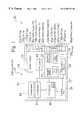
- FIG. 1is a block diagram of a self-test electronic assembly unit
- FIG. 2is a block diagram of a multiple bay test rack, housing one or more self-test electronic assembly units, connected to a command unit and one or more display monitors;
- FIG. 3is a block diagram of loop back connections for the self-test system
- FIG. 4is a front view of a spring loaded back plane and a back plane support bracket
- FIG. 5is a front oblique view of a back plane and backplane to assembly connectors
- FIG. 6is a back view of a test bay mechanism
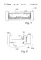
- FIG. 7is a front view of a test bay mechanism
- FIG. 8is a right side view of a test bay mechanism
- FIG. 9is a front perspective view of a test bay mechanism
- FIG. 10is a rear top perspective view of a test bay mechanism
- FIG. 11is a front view of a multiple bay test rack enclosure
- FIG. 12is a side view of a multiple bay test rack enclosure
- FIG. 13is a rear view of a multiple bay test rack enclosure
- FIG. 14is a bottom perspective view of a multiple bay test rack enclosure
- FIG. 15is a first block diagram for an assembly which can perform self-testing
- FIG. 16is a second block diagram for the assembly which can perform self-testing shown in FIG. 15;
- FIG. 17is a detailed block diagram of preferred generation, storage and transfer of security keys during the manufacturing process
- FIG. 18is a flowchart showing the generation, storage and transfer of security keys within a security microprocessor.
- FIG. 19is a system block diagram of an installed preferred self-test assembly in communication with a central computer.
- FIG. 1is a block diagram of a self-test electronic assembly unit 10 , which includes circuitry 14 comprising a plurality of interconnected components 16 within a base, chassis, or enclosure 12 .
- One or more of the components 16may include electronically readable information 17 , such as component model number, component serial number, or component batch number.
- the circuitry 14 shown within FIG. 1also includes a processor 18 and storage 20 .
- the storage 20comprises one or more memory devices, such as but not limited to programmable read only memory (PROM), programmable random access memory (PRAM), flash memory, one or more hard drives, or removable media.
- PROMprogrammable read only memory
- PROMprogrammable random access memory
- flash memoryone or more hard drives, or removable media.
- the storage media 20includes test logic 22 and sample data 23 , which are used by the self-test electronic assembly 10 to conduct various self-testing, such as functional diagnostic testing and/or extended burn-in testing.
- the self-test electronic assembly 10stores the retrievable test results 24 internally, such as within memory 20 .
- a critical and time-consuming element of most conventional manufacturing processesis the testing of manufactured goods.
- the self-test electronic assembly 10provides efficient and consistent self-testing, and stores results internally, thereby increasing manufacturing speed, and improving the quality of each of the manufactured self-test assemblies 10 .
- the self-test-electronic assembly 10also typically includes a retrievable serial number 29 , and in preferred embodiments, includes security software, by which the self-test electronic assembly 10 may establish security keys 270 , 272 (FIG. 17 ).
- the self-test electronic assembly 10includes a temperature sensor 28 and a cooling fan 26 .
- the temperature sensor 28logs it, ambient or internal operating temperatures for the self-test electronic assembly 10 , such as during initial testing, as well as during ongoing operation for the assembly 10 .
- the processor 18controllably powers the cooling fan 26 in response to elevated ambient or internal operating temperatures measured by the temperature sensor 28 .
- the self-test electronic assembly 10has a connection interface 30 , which includes various input and output signal connectors and a power connector 48 a .
- the preferred embodiment shown in FIG. 1has a connection interface 30 that includes video output 32 a , video input 34 a , right channel audio output 36 a , left channel audio output 38 a , left channel audio input 40 a , right channel audio input 42 a , a modem connector 44 a , an RF connector 47 a , and a power connector 48 a .
- Preferred embodimentsoptionally include S-video output 31 a , S-video input 33 a , serial port and IR blaster connections.
- the self-test assembly 10When the preferred embodiment of the self-test assembly 10 shown in FIG. 1 is installed by the final user (FIG. 19 ), the self-test assembly 10 is typically connected to an incoming television signal cable 296 , a telephone line 292 , and a television set 294 , as well as to supplementary components, such as video cassette recorder 270 , a stereo system 266 , audio speakers 268 a , 268 b , and other devices, such as remote controllers, video game devices, or Internet connection devices (e.g. such as a WebTVTM console and remote WebTVTM keyboard).
- supplementary componentssuch as video cassette recorder 270 , a stereo system 266 , audio speakers 268 a , 268 b , and other devices, such as remote controllers, video game devices, or Internet connection devices (e.g. such as a WebTVTM console and remote WebTVTM keyboard).
- the detailed test results 24which are stored internally, provide valuable and consistent information 24 to guide the troubleshooting and repair of failed units 10 .
- the detailed and logged test results 24accompany the assembly 10 , and are easily accessible, to troubleshoot an fix failed assembly units 10 , without requiring a technician to manually tag and list detected problems.
- the overall yield of truly acceptable assembly units 10is therefore increased, since the rigorous and uniform self-testing ensures high quality of passing assembly units 10 , and fixable assembly units 10 are identifiable and efficiently remedied.
- FIG. 2is a block diagram of a test system 50 for self-test assemblies 10 .
- the self-test system 50is typically used in conjunction with the manufacture of self-test assemblies 10 , in which the condition of components 16 , circuits 14 , and self-test assemblies 10 are to be tested for quality and performance, such as before distribution and eventual shipment to a customer.
- a multiple bay test rack 52typically includes one or more test banks 54 , which contains a plurality of test bays 56 .
- the multiple bay test rack 52allows self-testing of large numbers of self-test electronic assemblies 10 at a time, from one or more manufacturing facilities 53 .
- the internal test procedures 22 stored within each assembly 10combined with the use of one or more multiple bay test racks 52 , allow efficient and similar diagnostic and run-in tests to be performed at one or more test system areas 50 .
- Each test bay 56provides a separable backplane connection 104 (FIG. 4) to an installed self-test electronic assembly unit 10 .
- Each test bay 56is also connected to the status module 51 , through a simulated PSTN phone line connection 58 and a modem 60 , to a terminal server 62 .
- test results on all units and yield informationis monitored.
- This datacan also be monitored from a remote location.
- a remote locationFor example, while a corporate office is located in a first location (e.g. California), a related manufacturing facility may commonly be located at a remote domestic of international location (e.g. Mexico, Europe). A user at a remote location may therefore monitor test results, yield data and failure information, in real time and dynamically.
- the terminal server 62is connected to a computer station 64 , which includes a computer 66 having internal storage 63 , a connected monitor 68 , and one or more input devices 70 , such as a keyboard and mouse.
- the computer 64self-test system software which typically includes a graphic user interface 65 , allowing a test operator to quickly review the operation of the test system 50 .
- each terminal server 62allows the routing of test information from eight test bays 56 and eight self-test assembly units 10 , with eight dedicated modems 60 and phone line connections 58 to the terminal server 62 .
- each terminal server 62allows the connection and testing of sixteen self-test assembly units 10 , whereby all sixteen self-test assembly units 10 are individually connected to the terminal server 62 and computer 64 .
- the self-test electronic assemblies 10typically arrive at the testing area 50 from an assembly area 53 , typically without bezel and cover installed on the enclosure 12 . Each self-test electronic assembly 10 is then placed into a test bay 56 within the test rack 52 .
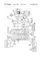
- FIG. 3is a block diagram 90 of loop back connections 92 for each test bay 56 of a test rack 52 within a self-test system 50 .
- Each test bay 56 within the test rack 52preferably includes a back plane 104 (FIG. 4 ), which includes loop back circuits 92 a - 92 n for modem, power, video, audio, serial port, and IR blaster interfaces. The test operator or technician is therefore not required to manually connect cables to a self-test electronic assembly 10 .
- the service operatoris only required to place a built self-test assembly 10 into a vacant tray 154 (FIGS. 8 , 9 ) in a test bay 56 , and slide the tray 154 into the test bay 56 .
- the connection interface 30is connected to the backplane 104 .
- connection interface 30The connectors 31 a , 32 a , 33 a , 34 a , 36 a , 38 a , 40 a , 42 a , 44 a , 46 a , 47 a , 48 a on the connection interface 30 are mate with the matching rear connectors on the backplane 104 , and the tray 154 and installed self-test electronic assembly 10 moves automatically back into the test rack chassis 150 (FIGS. 8 , 9 ).
- FIG. 4is a front view 100 of a back plane 104 attached to a back plane support bracket 102 by spring-loaded attachment 106 . Movement of the back plane 104 is limited by one or more back plane stops 108 . One or more alignment holes 110 are defined in the back plane support bracket 102 , and allow the back plane support bracket to slide in relation to a test bay assembly 150 (FIGS. 7 - 10 ).
- FIG. 5is a front oblique view of a back plane 104 and backplane support bracket 102 .
- the back planeincludes connectors video output 32 b , video input 34 b , right channel audio output 36 b , left channel audio output 38 b , left channel audio input 40 b , right channel audio input 42 b , a modem connector 44 b , an RF connector 47 b , and a power connector 48 b , which mate to the connection interface 30 of an installed self-test assembly 10 .
- FIG. 6is a back view of a test chassis mechanism 150 .
- the back plane 104provides a connection to the test system 50 , and provides removable connections to an installed self-test assembly.
- FIG. 7is a front view of a test chassis mechanism 150 , with an installed assembly chassis 12 .
- the connection interface 30 of the assembly chassis 12connects to the various connectors 32 b - 48 b in the spring loaded back plane 104 .
- FIG. 8is a right side view of a test bay mechanism 150 , which includes one or more slides 152 in a mobile frame 154 .
- An air cylinderis preferably used to move the mobile frame 154 in relation to the rear stationary frame 158 .
- FIG. 9is a front perspective view of a test bay mechanism 150 .
- the alignment holes 110 in the back plane support bracketmove along alignment slides 152 .
- FIG. 10is a rear top perspective view of a test bay mechanism.
- the test bay mechanism 150preferably includes a switch, which senses if a self-test assembly 10 is installed within the test frame 154 . When an operator installs a self-test assembly 10 , the switch closes, which is then sensed through a connection contact in the serial port. The serial port feeds back to the test system 51 , which allows the test system 51 to detect if a whether self-test assembly 10 is installed. If the self-test assembly 10 begins proper communication and self-testing, the control system monitors the self-test sequence. Alternatively, if the self-test assembly 10 is installed, but does not respond to further communication, the control system 50 , 51 can detect and display an early failure of the assembly 10 . In one embodiment, such a failure may be transferred to an indicator light at the test bay 56 , or is displayed on the command computer user interface 65 .
- FIG. 11is a front view 162 of a test cabinet 160 for a multiple bay test rack enclosure 52 , having a plurality of test bays 56 , louvered panels 164 , a lower area for test rack parts or tools, or for supplementary equipment cooling fans.
- the test cabinet 160also includes rolling and locking casters 168 , whereby the test cabinet 52 may be moved, such as within the test facility 150 .
- FIG. 12is a side view of a multiple bay test cabinet 160 for a test rack enclosure 52 , having a front side 162 which allows self-test assemblies 10 to be removably installed into test bays 56 , and a back side 172 , which allows rear access and rear door hinges 170 , for power connections 78 and modem connections 58 .
- FIG. 13is a rear view 172 of a multiple bay test rack enclosure 52 .
- Rear doors 174 having ventilation louvers 176are hingeably mounted 170 on the rear side 172 of the test cabinet 160 .
- FIG. 14is a bottom perspective view of a test cabinet 160 for a multiple bay test rack enclosure 52 .
- Self-test assemblies 10typically start their self-test procedures as soon as they are installed in the test rack 52 , and typically are not required to wait until each test bay 56 in the test rack 52 is filled with self-test assemblies 10 , to proceed with self-testing. Ongoing diagnostic or run-in testing is monitored through the command module 64 (FIG. 2 ).
- test procedure software 22 and test data 23are typically loaded onto and stored within memory 20 of each self-test assembly 10 when the self-test assembly is initially installed in a test bay 56 .
- Each self-test assembly 10then tests itself, based on the stored test procedures 22 . Since each self-test assembly 10 tests itself, the time required to test one self-test assembly 10 is the same as the time required to test a large number of self-test assemblies 10 (e.g. 200 units).
- the test system 50is therefore scalable, and the capacity can easily be increased, with the addition of test racks 52 of test bays 56 , without requiring more operators for the manufacturing test area 50 , and without increasing the test time for each self-test electronic assembly 10 .
- the video 41 and audio 43 , 45 test output connections of each the self-test assemblies 10are preferably connected to a display monitor 76 , which receives and displays test result information from each self-test assembly 10 .
- the test rack 52is connected 72 to one or more test display monitors 76 .
- a video selector switch 74is connected to the video output ports 72 of each test bay 56 , and is switchably connected to a single display monitor 76 , such that the output signals from a selected self-test assembly 10 is selectably monitored by an operator.
- each test bay 56are each connected to a separate, dedicated display monitor 76 , such that the output signals from several selected self-test assemblies 10 can be monitored concurrently by an operator.
- separate, dedicated 13 ′′ television monitors 76are used, each having composite (i.e. video and audio) signal connections.
- the placement of individual dedicated monitors 76 next to each test bay 56allows operators to easily view the ongoing testing of self-test assemblies, and allows operators to easily distinguish passing units 10 or failed units 10 . Therefore, passing self-test assemblies 10 are prevented from being placed into a reject area 84 , while faulty assemblies 10 are more fully prevented from being placed into a passing area 80 .
- the test rack 52can be a functional diagnostic self-test station, or can be a “burn-in” self-test station.
- a functional diagnostic test stationtypically performs all functional tests once, while a bum-in station typically performs functional tests repeatedly, such that self-test assemblies 10 are commonly run for several hours (e.g. 4,8, or 24 hours).
- Each bay 56 within a test rack 52is typically separately reconfigurable, such as for either functional testing or for “burn-in” testing.
- the command station 64typically displays which type of testing is performed for the selected bay 56 .
- all bays 56 in a single rackare configured similarly (e.g. either each bay 56 in a test rack is used for function testing, or alternatively, each bay 56 in a test rack 52 is used for bum-in testing).
- the user interface display 65 on the command station 64is preferably color-coded, providing a distinguishable display for the type of testing performed. While a display monitor 76 receives and displays test information and results from a single self-test assembly 10 , the user interface 65 on the command station 64 can display the testing status of one or more self-test assemblies concurrently. When displaying the status for a self-test assembly, a displayed color for an installed assembly is typically used to distinguish a “passing” assembly from a “failed” assembly. For example, in one embodiment, the displayed color for a test bay on the user interface 65 is green for a “passing” unit, displayed color for a test bay on the user interface turns red for a “failed” unit. The colored indicator flashes while testing is in progress, and remains solid (either green or red) when testing is completed.
- each self-test assembly 10or alternatively, the test bay 56 in which a self-test assembly 10 is installed, includes light emitting diodes (LED's) for testing purposes, in similar colors and operation to the displayed colors on the user interface 65 . If a self-test assembly 10 fails, a red test LED is illuminated on the self-test assembly 10 , whereas if the self-test assembly passes all tests, a green test LED is illuminated on the self-test assembly 10 . While the self-test assembly is testing, the green test LED blinks.
- the preferred test LED's on the chassis 12 of a self-test assemblyprovide an efficient local determination of the status of tests, so that a test operator or technician can quickly and accurately identify and divert passing or failed self-test assemblies correctly.
- a self-test electronic assembly 10is placed within the test rack 52 , it is automatically powered on.
- the processorestablishes a PPP connection, and performs an FTP get to obtain and store the required test logic 22 .
- the processor 18then executes a diagnostic testing script, based upon the stored test logic 22 .
- the self-test electronic assembly 10performs several diagnostic tests while installed within the test rack 52 .
- the self-test electronic assembly 10updates the server 62 with the results, either on a continuous basis, as tests are performed, or as a final test report, when all functional tests are complete.
- Each testbuilds increasing confidence in a self-test electronic assembly 10 , as it checks components 16 and circuitry 14 , such as flash memory, system RAM disk, and signal encoders and decoders (FIGS. 15 , 16 ).
- Diagnostic testingruns in each self-test electronic assembly 10 as a stand-alone process, since the test logic and control 22 resides within the self-test electronic assembly 10 , and the processor 18 performs the required tests, and creates a report card 24 . Since each self-test electronic assembly 10 is responsible for it's own testing, an increase in the number of self-test electronic assembly units 10 within a test rack 52 does not increase the test time. It takes the same amount of time to test thirty-two units 10 as it does to test a single unit 10 .
- the self-test electronic assembly 10is able to perform testing of several of the components 16 and circuitry 14 , by sending signals 32 , 36 , 38 , 46 through loop-back circuits 92 a - 92 e , and processing or comparing the “received” signals 34 , 40 , 42 , 47 (e.g. such as audio or video signals) to the original data 23 , to confirm component and assembly performance.
- the processor 18controllably sends one or more stored test signals 23 out from the output ports, which are then looped back to the input ports of self-test assembly unit 10 .
- the returning signalsare then processed (e.g. such as through decoding components 16 ).
- the processor 18compares the received and processed signal to the original stored signal 23 , to confirm that the returning signal is correct (e.g. identical to the original stored test images located on the storage drive 20 ).
- the self-test assembly unit 10can also receive a standard television signal feed (e.g. having both video and audio signals), which it processes, and the performs audio and video loopback testing.
- the self-test assembly unit 10can perform testing of the transmission reception, processing, encoding, and decoding of other data, such as over the connected serial modem 60 .
- the self-test assembly unit 10provides full encoding and decoding of signals.
- the self-test assembly 10tests the encoding and decoding operations, typically be taking a test signal, such as stored data 23 or received signal data, encoding the signal, sending the signal through the output ports, (e.g. 32 , 36 , 38 ), across the loopback circuits 92 , and into the input ports (e.g. 34 , 40 , 42 ), where the self-test assembly decodes the encoded data, and compares the decoded data to the original signal 23 , and distinguishes whether or not the self-test assembly unit 10 received the same signal 23 that was originally encoded and transmitted.
- a test signalsuch as stored data 23 or received signal data
- the user interface 65 running on the test server 62displays the ongoing or final status of the tests.
- a self-test assembly 10 which is being testedis shown in the selected test bay 56 within the user interface 65 , and is indicated by the color yellow, with a display message, indicating the “TESTING” status. If the self-test electronic assembly 10 passes all the required tests, the displayed bay for the installed self-test electronic assembly 10 turns green, and displays a “SHIP IT” message, whereby the operator can remove the desired self-test assembly 10 from the test rack 52 , and place it in a packing and shipping area 80 (FIG. 2 ).
- the display indicatorturns red, and displays a “FAILED” message, whereby the operator can remove the desired self-test assembly 10 from the test rack 52 , and place it in either a repair area 82 or a reject area 84 (FIG. 2 ).
- the command module 64quickly receives a signal which indicates that one or more key functional areas 14 , 16 of the self-test assembly 10 is faulty, so that the assembly may be properly routed to either a repair area 82 or to a reject area 84 .
- the self-test assembly unit 10stores the test results 24 as a retrievable log file. There is no requirement from an external operator to determine which part of the device failed, or a requirement to tag.
- the retrievable log file 24is stored within the device 10 , and therefore accompanies with the assembly 10 , if it is transferred from the testing area to a repair area 82 .
- the log file 24can be retrieved, and is matched to the serial number 29 (FIG. 1) on the chassis 12 .
- Run-in Testingis typically done on a sampled basis, either before or after functional diagnostic testing. In one embodiment, prior to functional diagnostic testing, a selected percentage of self-test assembly units 10 are tested (e.g. ten percent) for a specified extended time period (e.g. for four hours).
- run-in testingtypically includes the same tests as functional testing, the functional tests are repeatedly performed during the defined run-in period.
- the test rack 52 used for run-in testingcan also be configured to perform extended run-in tests. Since the same fixture 52 is preferably used for both functional testing and for extended run-in (burn-in) testing, there is no need for separate test fixtures, or for separate upkeep and training for separate test racks 52 .
- test rack 52For run-in testing, self-test electronic assemblies 10 are placed into the test rack 52 , as described above.
- the output signal portse.g. the audio and video (A/V) ports
- A/Vaudio and video
- Connections to the test server 72 , one or more display monitors 76 , and power 78are also made automatically by the test rack 52 .
- each of the self-test assemblies 10can either start run-in testing as soon as they are installed into a test bay 56 , or all self-test assemblies can be started at one time, such as when all test bays 56 within a test rack 52 contain a self-test assembly 10 .
- the user interface 65 running on the command module 64typically shows the status of tests at all times during run-in testing.
- a display monitor 68 , 76 attached to the system 50displays either a “PASS” or a “FAIL” message. Failure information is stored within each self-test assembly 10 , and is also preferably stored in a log file on the disk drive 63 of the control unit 64 .
- test user interface 65collects all the process information, and stores yield data and failure information, such that no manual operation is required from the operator, either for testing, or for SPC data collection.
- the self-test assembliesUpon successful completion of either diagnostic and run-in tests, the self-test assemblies automatically exit the self-testing mode.
- the passing self-test assembliesare then typically moved, either manually by an operator, or automatically, in a robotic manufacturing and testing facility 53 , 50 to a packing area 80 .
- Outer covers and bezelsare then typically installed on passing self-test assemblies 10 , which are then prepared for shipment (e.g. visual inspection, bagging), and are then packed, typically with supplementary materials, such as connection cabling and manuals.
- the retrievable data 24 within a “failed” self-test assembly 10is preferably used in a troubleshooting and repair area 82 .
- Each testcreates a standard output, and a standard error file, within the test results 24 .
- the most likely source or sources of any problemcan often be determined (e.g. a particular video path, or one or more chips).
- the retrievable data 24is preferably used for failure analysis and repair, thus eliminating the need for manual tagging or data entry by an operator.
- a repair area computer 83is connected to the self-test assembly 10 , and retrieves the stored test results and error file 24 .
- the repair area computer 83preferably includes failure analysis software, which analyzes the retrieved test report 24 , and suggests potential problems, and preferably suggests solutions.
- the repair computer 83may suggest that the repair technician test one or more components 16 (e.g. such as suggesting that the technician measure voltage across pins on a microprocessor).
- the repair computer 83also preferably shows graphically the desired (or problematic) sample pin signal waveforms.
- the softwarepreferably suggests further analysis or solutions.
- a statistical display on the repair computer 83accompanies potential reported problems.
- either the self-test assembly 10 , or the repair computer 83preferably reports the statistical likelihood of the source of the reported problem (e.g. such as a reported “ninety percent chance of a problem at a first component 16 a , as detected by a voltage between pin 1 and 8 , and a ten percent chance of a problem at a second component 16 b , as detected by a voltage between pin 1 and 16 ).
- the self-test assembly 10 , test system 50 , and repair computer 83can therefore build “wisdom” to troubleshoot assemblies 10 , based upon prior testing and solutions on one or more self-test assemblies 10 , and also from input from technicians and engineers.
- the stored test report 24 within each self-test assemblytherefore provides a valuable tool that helps a technician troubleshoot and repair the self-test assembly 10 .
- the stored and retrievable test report 24therefore helps to diagnose and correct problems efficiently, and lowers the required skill level of repair technicians, thus lowering the average price for self-test assemblies 10 .
- a summary fileis prepared at the command computer 64 , and is preferably printed, which shows the quantity of self-test electronic assemblies 10 tested, the serial number 29 of each tested assembly 10 , the test results for each assembly 10 , the overall yield (i.e. percent self-test electronic assemblies 10 passed for total of self-test electronic assemblies 10 tested), and a summary of the types of errors or rejected self-test assemblies 10 throughout the shift or day.
- the server 62is also preferably interconnected to the manufacturing area 53 , so that the results of testing status, units tested, and yield are optionally viewed, either in real time, or in storage for later retrieval, for review and reporting.
- the test system 50preferably reports which assemblies 10 have been tested, and what the current yield of the facility 53 , 50 (i.e. percent passing) for the time period.
- the daily yieldis accessible.
- the weekly yieldis accessible. While this type of report is desirable in manufacturing environments, the level of automation offered by the self-test assemblies 10 and self-test system 50 is unique. Furthermore, the level of diagnostic testing and troubleshooting information provided by each self-test assembly 10 is unique.
- Self-test electronic assembly units 10typically include a distinct identification (e.g. a serial number) 29 , which allows a test operator or user to determine the date of manufacture and manufacture site.
- a distinct identificatione.g. a serial number
- Bar codes on components and chassisare sometimes used for identification.
- Bar code readerstypically come into visual contact with the bar codes on the components and chassis along the assembly line.
- External meanssuch as supplementary computers, may be used to log the identifying bar codes, to track the components and their associated assemblies.
- the self-test electronic assembly 10preferably tracks and logs the identity of it's components internally.
- Components 16 within a self-test assembly 10commonly have unique system identification 17 , which can often be determined by the processor 18 .
- each drive 20has a unique serial number 17 . Therefore, each self-test assembly unit 10 has a unique system identifier 29 , and drive serial number 17 .
- identifying informationwhich may be detected and stored.
- the stepping number 17 on the CPU 18 and on other components 16such as on an encoder or decoder may also be identified.
- each self-test assembly 10preferably reads all available identification strings 17 from components 16 which include such information 17 (such as for an encoder), and logs the accessible identification strings 17 , such as within memory 20 .
- the self-test electronic assembly 10preferably keeps track of all accessible information 17 , and automatically links them to the serial number 29 of each self-test electronic assembly 10 .
- the internal, stored status 24 of a self-test electronic assembly 10therefore preferably includes functional test information, as well as all readable component information 17 .
- the command station 64preferably provides a display or warning, such as for a plurality identified failed self-test assemblies, which have an identified particular component 16 that is faulty. For example, if a new batch of encoders arrive at a manufacturing facility 53 (each having a trackable stepping number 17 ), for which a large percentage of self-test assemblies fail encoding and decoding loopback tests, the test system 51 preferably identifies the common problem, and preferably links the problem to the similar recorded stepping number 17 of the new batch of decoders.
- FIG. 15is a first circuit block diagram 170 a for a preferred self-test electronic assembly.
- FIG. 16is a second circuit block diagram 170 b for the self-test assembly 10 shown in FIG. 15 . While a basic self-test assembly 10 may be implemented for a wide variety of manufactured goods, the preferred self-test assembly embodiment 10 shown in FIG. 15 and FIG. 16 receives television program scheduling data, provides a time shifting system for television viewing, and also provides program guide data and control.
- the microprocessor 18is an IBM PPC403GCX processor.
- the serial port 172 of the processor 18is linked to glue logic 174 , security microprocessor 176 , IR board 178 , and IR output jack 180 .
- the processor 18is also linked to a reset 182 , as well as to an address bus 184 and a data bus 186 .
- a series of Address MUX's 188are attached to the address bus 184 , and are also linked to a series of EDO_DRAM 190 , which are also connected to the data bus 186 .
- Flash memory 192is also linked to the address bus 184 and data bus 186 .
- a DSS port UART 194is linked to the address bus 184 and data bus 186 , and is connected to a DSS Port XVR 196 and a DSS I/O Jack 198 .
- a modem MCU 200which in one embodiment is a Rockwell Part No. RC336LU, is linked to the address bus 184 and data bus 186 , and is connected to a modem MDP 202 , which in one embodiment is a Rockwell Part No. RC336LDU. Flash memory 204 and SRAM memory 206 are also linked to the modem MCU 200 and to modem MDP 202 .
- DAA devices 208 , 210 , and 212are Krypton Part Nos. K951C, K934L, and K952 respectively.
- DAA 212is also connected to RJ 11 connector 214 .
- a 12 C bus 216is connected to a clock chip 218 , and to a battery 220 .
- the address bus 184 , data bus 186 , and 12 C bus 216are attached to media switch ASIC 222 .
- the media switch ASIC 222is attached to an IDE interface 224 , an MPEG2 A/V decoder 226 (which in one embodiment is an IBM CS 22 ), and an MPEG2 video encoder 228 (which in one embodiment is a Sony Part No. CXD1922Q).
- Test logic 22is input through IDE interface 224 .
- An MPEG2 audio encoder 230is also linked to the media switch ASIC 222 , and to the MPEG2 video encoder 228 .
- the MPEG2 video encoder 228uses SDRAM 232 .
- a bus switch 234is also linked to the address bus 184 , the data bus 186 , and to both the MPEG2 video encoder 228 and the MPEG2 audio encoder 230 .
- An NTSC video encoder 236(which in one embodiment is a Brooktree Part No. BT865A) is linked to the MPEG2 AN decoder 226 .
- the NTSC video encoder 236is attached to a dual op-amp 238 (which in one embodiment is an Elantec Part No. EL2250C), which is attached to RCA stacks 240 , 242 .
- the NTSC video encoder 236also includes S-video output connection 31 .
- An audio mixer crystal 244(which in one embodiment is an IBM Part No.
- CS4333is attached to media switch ASIC 222 , and to a quad op-amp 246 (which in one embodiment is a Motorola Part No. MS33204D), which includes RCA stack connectors 36 , 38 .
- a 3 in 1 tuner 248(which in one embodiment is an Alps Part No. TMDH2xxxx series) is attached to the NTSC video encoder 236 , to the quad op-amp 246 , and is linked to an MTS audio decoder 250 , and to an NTSC video decoder 252 .
- the preferred embodiment of the self-test assembly 10 shown in FIG. 15 and FIG. 16is used as the platform for delivering a distributed television service.
- a key element for providing an economic and viable distributed television serviceis the provision for secure, authenticated communications between each receiver self-test assembly and a central database 264 (FIG. 19) of television viewing information. Therefore, preferred embodiments of the self-test electronic assembly 10 operate under a secure architecture. As well, secure, authenticated communications are preferred for other embodiments of the self-test assembly 10 .
- FIG. 17is a detailed block diagram of the transfer of a security software module 25 (FIG. 1) into the security microprocessor 176 , and the subsequent generation, storage and transfer of security keys 270 , 272 within the security microprocessor 176 during the manufacturing process.
- the security software module 25includes an authentication algorithm 258 , an encryption and decryption algorithm 260 , and a key generation algorithm 262 .
- FIG. 18is a flowchart 278 showing the generation, storage and transfer of security keys 270 , 272 within the security microprocessor 176 .
- the assemblyWhen the self-test electronic assembly 10 is initially booted (or when self-testing is completed), the assembly generates it's own secret key 270 , to restrict access into and out of the assembly 10 .
- the internal security microprocessor 176downloads 264 the security software module 25 to internal memory 266 .
- the security microprocessor 176then runs the internally programmed security software 25 to generate a security key pair 268 , comprising a public key 272 and a private key 270 .
- the private key 270is stored 274 within the internal memory 266 of the security microprocessor 176 , and the public key 272 is sent 276 , along with the test data, to the command unit 62 , 64 .
- the security processor 176then preferably disables changes to the security microprocessor software environment (e.g. such as by blowing a hardware fuse), thus preventing unauthorized use, access, or modification.
- the private key 270is used as an authentication and security mechanism to pass session keys to the self-test electronic assembly 10 , as well as to authenticate external services.
- the private key 270never appears on any of the buses (e.g. data bus 186 ) of the self-test assembly 10 , nor is it ever transferred from the assembly 10 .
- the external systemuses the private key 270 to communicate with the self-test assembly 10 and control it, and to authenticate the system 50 to the self-test assembly 10 , thereby accessing data and operational history about the self-test assembly 10 . Therefore, the self-test assembly generates its own private key 270 , and transfers the public key 276 , which allows the system 50 to communicate with the self-test assembly 10 .
- each self-test assembly 10Since each self-test assembly 10 generates its own secret private key 270 internally, and does not distribute the private key 270 externally, access to the self-test assembly 10 is strictly controlled.
- a qualified external systeme.g. the test system 51 or other qualified system
- each public key 272is only valid for a particular self-test assembly 10 . Therefore, the self-test assembly 10 establishes a secure, encrypted communication channel to qualified external systems.
- Diagnostic testing of the preferred circuitry 14 shown in FIG. 15 and FIG. 16consists of a series of core functional test units, designated as Core 0 functionality tests, Core 1 functionality tests, and Core 2 functionality tests.
- Core 0 functionality test procedures 22reside in flash memory, and in one embodiment consists of Flash/CRC tests, Power PC internal tests, System RAM memory tests, and Disk/IDE component tests.
- Core 1 functionality test procedures 22are typically stored in Kernel memory, and typically consist of a series of register tests on the level of the integrated circuits (IC's), which for the embodiment shown include the user level harness test, MediaSwitch register test, MPEG video encoder register test, MPEG audio encoder register test, a 12 C register test (for the NTSC encoder, NTSC decoder stereo (MSP) encoder, RTC, and tuner), 12 S register test, MPEG decoder register test, MPEG AV decoder SDRAM tests, and MPEG video encoder SDRAM tests.
- IC'sintegrated circuits
- Core 2 functionality test procedures 22consist of full audio/visual (A/V), IR, and serial port loopback tests.
- the Core 2 functionality test proceduresare located on Kernel memory, and typically consist of YUV colorbars and their encoded video representation on the storage drive, a series of decode, encode, decode loopback operations and comparison of video signals, audio standard signals and their encoded representation on the storage drive, a series of decode, encode, decode and comparison of the audio signals, VBI testing (which is performed on the RF, composite, and S-Video I/O's), IR loopback and programming, temperature sensing, time and date set operations, cooling fan testing, serial port testing, IR blaster connector testing, and modem command testing.
- the modem testingtypically starts with UUT dialing an external modem (e.g. test modem 60 ), through a PSTN simulator 58 , and sending a test file to the test PC 64 through a terminal server 62 . Diagnostic tests are completed, even if there is an early failure, or if multiple failures are logged. The failure information is stored in a log file 24 on the 15 S self-test assembly drive 20 .
- an external modeme.g. test modem 60
- PSTN simulator 58e.g. test modem 60
- test filee.g. test PC 64
- the failure informationis stored in a log file 24 on the 15 S self-test assembly drive 20 .
- the techniques described for the self-test assembly 10may be implemented on a wide variety of manufactured goods.
- the preferred self-test assembly embodiment 10 shown in FIG. 15 and FIG. 16receives television program scheduling data, provides a time shifting system for television viewing, and also provides program guide data and control.
- FIG. 19is a system block diagram of an installed preferred self-test assembly 10 in communication with a central computer 284 .
- a self-test assembly 10is typically connected to power 298 , an incoming television signal cable 292 , a telephone line 290 , and a television set 294 , as well as to supplementary components, such as video cassette recorder 295 , a stereo system 286 , audio speakers 298 a , 298 b , and other devices, such as remote controllers, video game devices, or Internet connection devices (e.g. such as a WebTVTM console and remote WebTVTM keyboard).
- the self-test assemblyis also connected, such as through the telephone network 290 , to a central system 284 .
- the preferred self-test assembly 10selectively captures programming signals, and stores them (e.g. to an internal disk drive), for later retrieval and viewing).
- the program guide datahelps the device controllably capture and store selected programs for the viewer, and preferably suggests available programming which matches an entered profile for the viewer.
- the preferred self-test assembly 10optionally delivers suggestions on further viewing, based on the viewer's viewing habits (e.g. the self-test assembly 10 may detect if a viewer typically watches “do-it-yourself” type shows, and preferably suggests similar shows, or portions of upcoming shows, which offer related programming content, such as woodworking, gardening, or home maintenance programming).
- the preferred self-test assembly 10can also communicate information back to the central system 284 , such as operating parameters (e.g. measured temperature), or retrieved test results of periodic self-testing (thus tracking the long-term performance of the assembly).
- the preferred self-test assembly 10can optionally communicate television viewing histories back to a central system 284 as well, where the central system 284 typically aggregates viewing information from a plurality of viewers, thus producing statistical viewing data, as desired. The aggregation of viewing data provides valuable information, without using or disseminating the viewing data of individuals.
- each assembled unit 10when the assembled units 10 are distributed to and operated at external locations 282 , each assembled unit 10 continues to monitor itself, and keeps track of external operation conditions, such as power failures, ambient or internal operating temperature.
- a temperature sensor 28is preferably used to track ambient or operating temperature, whereby a fan 26 may be run, as necessary.
- the self-test assemblycontinues to measure the temperature, and stores the information internally 24 .
- the self-test assembly unit 10communicates a central server 284 , through the modem connection 44 , and transfers such stored information.
- the central server 284receives and stores monitoring information from one or more assembled units 10 .
- the central server 284 or a connected computer 64preferably cross-correlates the in-situ performance of each assembled unit 10 to the original test data and manufacture date for the assembled unit 10 and internal components 16 a - 6 n , 20 , 22 , 26 , 28 .
- the systemtherefore provides a statistical mean-time to failure of the assemblies, and for any of the tracked components within the assembly.
- the self test assembly 10provides information on critical components,both during testing and after testing.
- Critical componentsare commonly defined as a small percentage of components within an assembly (e.g. 10 percent) which provide a high percentage of the manufacturing cost and reliable functionality for the assembly (e.g. 90 percent).
- the MPEG encoder, decoders, microprocessor 18 , and memory 20can presently be considered to be critical components 16 , due to their presently high cost, and their relative mean time between failure (as compared to other components 16 within the assembly 10 ).
- the self-test assembly 10preferably builds a database record based upon the components and test results for a period of time.
- the database recordis periodically sent to the central system 264 , and a central database is built, over time, both for each self-test assembly 10 , and for related self-test assemblies 10 (e.g. such as similar components 16 , circuitry 14 , or manufacture date).
- a self-test assembly 10preferably includes output to the user, depending on either the operating parameters or the test results.
- a self-test assembly 10that measures an extending operating temperature of 130 degrees Fahrenheit, the self-test assembly 10 can preferably output a message to the user to check the installed location (e.g. such as near a window in direct sunlight S, or near a heater).
- the apparatus and techniquescan be implemented for other devices and other testing and operating environments.
- the self-test electronic assembly 10 and its methods of useare described herein in connection with specific hardware, such as microprocessors, encoders, decoders, and signal processing devices, the apparatus and techniques can be implemented with other analog or digital components and circuitry, or any combination thereof, as desired.
Landscapes
- Engineering & Computer Science (AREA)
- Theoretical Computer Science (AREA)
- General Engineering & Computer Science (AREA)
- Quality & Reliability (AREA)
- Physics & Mathematics (AREA)
- General Physics & Mathematics (AREA)
- Computer Hardware Design (AREA)
- Test And Diagnosis Of Digital Computers (AREA)
- Testing Electric Properties And Detecting Electric Faults (AREA)
- Tests Of Electronic Circuits (AREA)
Abstract
Description
Claims (37)
Priority Applications (10)
| Application Number | Priority Date | Filing Date | Title |
|---|---|---|---|
| US09/357,183US6385739B1 (en) | 1999-07-19 | 1999-07-19 | Self-test electronic assembly and test system |
| CN200410030440.8ACN1282082C (en) | 1999-07-19 | 2000-07-12 | Self-test electronic assembly and test system |
| CNB008130043ACN100437507C (en) | 1999-07-19 | 2000-07-12 | Self-testing electronic assembly and testing system |
| DE60018574TDE60018574T2 (en) | 1999-07-19 | 2000-07-12 | SELF-TESTING ELECTRONIC DEVICE AND TEST METHOD THEREFOR |
| PCT/US2000/018955WO2001006370A1 (en) | 1999-07-19 | 2000-07-12 | Self-test electronic assembly and test system |
| AU59306/00AAU5930600A (en) | 1999-07-19 | 2000-07-12 | Self-test electronic assembly and test system |
| EP00945344AEP1203294B1 (en) | 1999-07-19 | 2000-07-12 | Self-test electronic assembly and test system |
| TW089114394ATW470878B (en) | 1999-07-19 | 2000-07-18 | Self-test electronic assembly and test system |
| US10/097,761US6643798B2 (en) | 1999-07-19 | 2002-03-14 | Self-test electronic assembly and test system |
| HK05104634.9AHK1071941B (en) | 1999-07-19 | 2005-06-01 | Self-test electronic assembly and test system |
Applications Claiming Priority (1)
| Application Number | Priority Date | Filing Date | Title |
|---|---|---|---|
| US09/357,183US6385739B1 (en) | 1999-07-19 | 1999-07-19 | Self-test electronic assembly and test system |
Related Child Applications (1)
| Application Number | Title | Priority Date | Filing Date |
|---|---|---|---|
| US10/097,761ContinuationUS6643798B2 (en) | 1999-07-19 | 2002-03-14 | Self-test electronic assembly and test system |
Publications (1)
| Publication Number | Publication Date |
|---|---|
| US6385739B1true US6385739B1 (en) | 2002-05-07 |
Family
ID=23404630
Family Applications (2)
| Application Number | Title | Priority Date | Filing Date |
|---|---|---|---|
| US09/357,183Expired - LifetimeUS6385739B1 (en) | 1999-07-19 | 1999-07-19 | Self-test electronic assembly and test system |
| US10/097,761Expired - LifetimeUS6643798B2 (en) | 1999-07-19 | 2002-03-14 | Self-test electronic assembly and test system |
Family Applications After (1)
| Application Number | Title | Priority Date | Filing Date |
|---|---|---|---|
| US10/097,761Expired - LifetimeUS6643798B2 (en) | 1999-07-19 | 2002-03-14 | Self-test electronic assembly and test system |
Country Status (7)
| Country | Link |
|---|---|
| US (2) | US6385739B1 (en) |
| EP (1) | EP1203294B1 (en) |
| CN (2) | CN100437507C (en) |
| AU (1) | AU5930600A (en) |
| DE (1) | DE60018574T2 (en) |
| TW (1) | TW470878B (en) |
| WO (1) | WO2001006370A1 (en) |
Cited By (86)
| Publication number | Priority date | Publication date | Assignee | Title |
|---|---|---|---|---|
| US20020014699A1 (en)* | 2000-05-10 | 2002-02-07 | Matsushita Electric Industrial Co., Ltd. | Semiconductor device, function setting method thereof, and evaluation method thereof |
| US20020055791A1 (en)* | 2000-03-27 | 2002-05-09 | Hiroshi Okamoto | Electronic equipment operating component function setting system |
| US20020071568A1 (en)* | 2000-09-08 | 2002-06-13 | Timothy Shuttleworth | Self-diagnostic system for monitoring electrical equipment |
| US20020104046A1 (en)* | 2001-01-31 | 2002-08-01 | Mohammad Saleem C. | Method and system for automatically testing a universal serial bus peripheral design |
| US6479310B1 (en)* | 2000-01-03 | 2002-11-12 | Motorola, Inc. | Method for testing a semiconductor integrated circuit device |
| US20030182074A1 (en)* | 2002-03-25 | 2003-09-25 | Gateway, Inc. | Automated method for installing and configuring a test suite on a unit under test |
| US20030184035A1 (en)* | 2002-04-01 | 2003-10-02 | Hyo-Sun Yu | Cart for electric or electronic devices having a testing function |
| US20030191805A1 (en)* | 2002-02-11 | 2003-10-09 | Seymour William Brian | Methods, apparatus, and systems for on-line seminars |
| US6643798B2 (en)* | 1999-07-19 | 2003-11-04 | Tivo, Inc. | Self-test electronic assembly and test system |
| US6671847B1 (en)* | 2000-11-08 | 2003-12-30 | Intel Corporation | I/O device testing method and apparatus |
| US6701003B1 (en)* | 2000-04-10 | 2004-03-02 | Innoventions, Inc. | Component identification system for electronic board testers |
| US20040045020A1 (en)* | 2002-08-29 | 2004-03-04 | Witt Jeffrey Michael | Commercial identification system |
| US6708327B1 (en)* | 1999-10-14 | 2004-03-16 | Techonline, Inc. | System for accessing and testing evaluation modules via a global computer network |
| US20040059903A1 (en)* | 2002-09-25 | 2004-03-25 | Smith John V. | Control system and method for rack mounted computer units |
| US20040073388A1 (en)* | 2002-10-15 | 2004-04-15 | Jonathan Dorny | Computerized methods for data loggers |
| US6725407B2 (en)* | 1999-09-23 | 2004-04-20 | Infineon Technologies Ag | Method and configuration for protecting data during a self-test of a microcontroller |
| US20040078185A1 (en)* | 2002-10-17 | 2004-04-22 | International Business Machines Corporation | Method and apparatus for automated analysis of hard disk drive performance |
| US20040102916A1 (en)* | 2002-11-21 | 2004-05-27 | Zhiguo Chen | Method for testing I/O ports of a computer motherboard |
| USD492209S1 (en) | 2003-03-12 | 2004-06-29 | Mitchell B. Nesenoff | Panel tester |
| EP1441491A1 (en)* | 2003-01-21 | 2004-07-28 | Agilent Technologies, Inc. | System and method for testing portable communications devices |
| US20040164166A1 (en)* | 2002-07-18 | 2004-08-26 | Intermec Ip Corp. | Indicator for communicating system status information |
| US20040177013A1 (en)* | 2003-02-27 | 2004-09-09 | Fenghua Zhou | Periodical auditing system and method |
| US20040215410A1 (en)* | 2003-04-25 | 2004-10-28 | Johan Siegers | System and method for fingerprinting of semiconductor processing tools |
| US20040221206A1 (en)* | 2001-05-29 | 2004-11-04 | Jacky Derouault | Device for validating an integrated circuit |
| US20040260984A1 (en)* | 2003-06-23 | 2004-12-23 | Samsung Electronics Co., Ltd. | Disc drive failure diagnostic system and method |
| US20050024545A1 (en)* | 2003-07-30 | 2005-02-03 | Borden George R. | Fast forward and skip remote control |
| US20050053008A1 (en)* | 2002-03-04 | 2005-03-10 | Griesing John Robert | Wireless device isolation in a controlled RF test environment |
| KR100501412B1 (en)* | 2002-12-10 | 2005-07-18 | 한국전자통신연구원 | Appratus and Method for Enterprise JavaBean Component Testing |
| US20050183128A1 (en)* | 2004-02-18 | 2005-08-18 | Inter-Cite Video Inc. | System and method for the automated, remote diagnostic of the operation of a digital video recording network |
| US20050194448A1 (en)* | 2002-07-18 | 2005-09-08 | Dusio Joseph M. | Enhanced system management and user assistance through software monitoring |
| US20060041887A1 (en)* | 2002-07-18 | 2006-02-23 | Intermec Ip Corp. | Expert system for solution management |
| US20060074807A1 (en)* | 2004-10-06 | 2006-04-06 | Sony Corporation | Method and system for content sharing and authentication between multiple devices |
| US20060075441A1 (en)* | 2004-10-06 | 2006-04-06 | Sony Corporation | Method and system for a personal video recorder comprising multiple removable storage/tuner units |
| US7075893B1 (en)* | 2002-03-04 | 2006-07-11 | Azimuth Systems, Inc. | Test system for simulating a wireless environment and method of using same |
| US20060224926A1 (en)* | 2005-03-30 | 2006-10-05 | Advantest Corporation | Diagnostic program, a switching program, a testing apparatus, and a diagnostic method |
| US7174233B1 (en)* | 2005-08-29 | 2007-02-06 | International Business Machines Corporation | Quality/reliability system and method in multilevel manufacturing environment |
| US7200775B1 (en) | 2002-10-04 | 2007-04-03 | American Megatrends, Inc. | Method and data structures for use in providing on-demand computer diagnostics |
| US7231549B1 (en)* | 2002-10-04 | 2007-06-12 | American Megatrends, Inc. | Method and apparatus for providing on-demand computer diagnostics |
| US7293203B1 (en)* | 2003-04-23 | 2007-11-06 | Network Appliance, Inc. | System and method for logging disk failure analysis in disk nonvolatile memory |
| US7334166B1 (en) | 2002-10-04 | 2008-02-19 | American Megatrends, Inc. | Method, system, and apparatus for providing and utilizing server-side entry points for use in diagnostics on-demand services |
| US20080077821A1 (en)* | 2006-09-22 | 2008-03-27 | Shenzhen Futaihong Precision Industrial Co.,Ltd. | Testing system and testing method thereof |
| US20080150539A1 (en)* | 2005-02-01 | 2008-06-26 | Siemens Aktiengesellschaft | Method and Circuit Arrangement for Verifying Electrical Contacts Between a First Output Pin of a First Power Switch of a Power Switch Device and an External Node and a Second Ouput Pin of a Second Power Switch of Said Power Switch Device and Said Node |
| US7401003B2 (en)* | 2002-02-04 | 2008-07-15 | Samsung Electronics Co., Ltd. | Diagnosis method and apparatus for peripheral device of host |
| US7457725B1 (en)* | 2003-06-24 | 2008-11-25 | Cisco Technology Inc. | Electronic component reliability determination system and method |
| US7483269B1 (en) | 2005-09-30 | 2009-01-27 | Maxtor Corporation | Test rack adapter for hard disk drive |
| US7529975B1 (en)* | 2008-03-31 | 2009-05-05 | International Business Machines Corporation | Method for testing processor subassemblies |
| EP2180706A2 (en) | 2003-12-18 | 2010-04-28 | Tivo, Inc. | Method of sharing personal media using a digital recorder |
| US7761259B1 (en) | 2004-05-26 | 2010-07-20 | William Brian Seymour | Methods and systems for testing evaluation modules |
| EP2268023A2 (en) | 2003-12-18 | 2010-12-29 | TiVo, Inc. | Method of sharing personal media using a digital recorder |
| EP2270732A1 (en) | 2002-01-08 | 2011-01-05 | TiVo, Inc. | Electronic content distribution and exchange system |
| US7984428B1 (en) | 2004-05-26 | 2011-07-19 | United Business Media Llc | Methods and systems for testing evaluation modules |
| US20110178627A1 (en)* | 2010-01-15 | 2011-07-21 | Rockwell Automation Technologies, Inc. | Integrated menu-driven manufacturing method and system |
| US8051447B2 (en) | 2007-12-19 | 2011-11-01 | Verizon Patent And Licensing Inc. | Condensed program guide for media content access systems and methods |
| US8069461B2 (en) | 2006-03-30 | 2011-11-29 | Verizon Services Corp. | On-screen program guide with interactive programming recommendations |
| US8103965B2 (en) | 2007-06-28 | 2012-01-24 | Verizon Patent And Licensing Inc. | Media content recording and healing statuses |
| WO2012030059A3 (en)* | 2010-09-02 | 2012-04-19 | 주식회사 지오네트 | Electronic card module including function of storing information regarding fabrication/maintenance/driving of a product |
| EP2490369A2 (en) | 2004-04-12 | 2012-08-22 | TiVo, Inc. | Multicasting multimedia content distribution system |
| US8352990B2 (en) | 2010-05-10 | 2013-01-08 | Encore Interactive Inc. | Realtime broadcast stream and control data conversion system and method |
| TWI383165B (en)* | 2005-12-16 | 2013-01-21 | Hon Hai Prec Ind Co Ltd | System and method of testing and repairing circuit boards online |
| US8418217B2 (en) | 2006-09-06 | 2013-04-09 | Verizon Patent And Licensing Inc. | Systems and methods for accessing media content |
| US8464295B2 (en) | 2006-10-03 | 2013-06-11 | Verizon Patent And Licensing Inc. | Interactive search graphical user interface systems and methods |
| US8510780B2 (en) | 2006-12-21 | 2013-08-13 | Verizon Patent And Licensing Inc. | Program guide navigation tools for media content access systems and methods |
| US8515773B2 (en) | 2001-08-01 | 2013-08-20 | Sony Corporation | System and method for enabling distribution and brokering of content information |
| US20130246848A1 (en)* | 2012-03-13 | 2013-09-19 | Invensense, Inc. | Method and system providng a self-test on one or more sensors coupled to a device |
| US8566874B2 (en) | 2006-10-03 | 2013-10-22 | Verizon Patent And Licensing Inc. | Control tools for media content access systems and methods |
| US8719893B2 (en) | 1999-03-15 | 2014-05-06 | Sony Corporation | Secure module and a method for providing a dedicated on-site media service |
| US8726159B2 (en) | 2007-01-05 | 2014-05-13 | Verizon Patent And Licensing Inc. | Content level navigation systems and methods |
| US20150324261A1 (en)* | 2009-02-05 | 2015-11-12 | Micron Technology, Inc. | Data Encoding Using Spare Channels in a Memory System |
| US9305590B2 (en) | 2007-10-16 | 2016-04-05 | Seagate Technology Llc | Prevent data storage device circuitry swap |
| US9384104B2 (en)* | 2013-11-27 | 2016-07-05 | International Business Machines Corporation | Testing a processor assembly |
| US9477287B1 (en)* | 2012-06-28 | 2016-10-25 | Amazon Technologies, Inc. | Optimizing computing resources |
| US20170102878A1 (en)* | 2015-10-09 | 2017-04-13 | Dell Products, Lp | System and Method for Monitoring Parameters at a Data Storage Device |
| US9679602B2 (en) | 2006-06-14 | 2017-06-13 | Seagate Technology Llc | Disc drive circuitry swap |
| US9836376B2 (en) | 2009-09-24 | 2017-12-05 | Contec, Llc | Method and system for automated test of end-user devices |
| US10103967B2 (en) | 2016-11-10 | 2018-10-16 | Contec, Llc | Systems and methods for testing electronic devices using master-slave test architectures |
| US10462456B2 (en) | 2016-04-14 | 2019-10-29 | Contec, Llc | Automated network-based test system for set top box devices |
| US10567975B2 (en) | 2005-10-04 | 2020-02-18 | Hoffberg Family Trust 2 | Multifactorial optimization system and method |
| US10581855B1 (en)* | 2017-02-08 | 2020-03-03 | Square, Inc. | Secured device manufacturing self-test |
| US10779056B2 (en) | 2016-04-14 | 2020-09-15 | Contec, Llc | Automated network-based test system for set top box devices |
| US11055695B2 (en)* | 2017-06-12 | 2021-07-06 | Discover Financial Services | Automated system and method for testing bank identification numbers in a networked system |
| US11234045B2 (en)* | 2016-09-29 | 2022-01-25 | D&M Holdings, Inc. | Audio-visual device |
| US11301840B1 (en) | 2015-03-30 | 2022-04-12 | Block, Inc. | Systems and methods for provisioning point of sale terminals |
| US20220317150A1 (en)* | 2021-04-05 | 2022-10-06 | Doble Engineering Company | Configurable test instrument for power equipment |
| CN115599427A (en)* | 2022-11-08 | 2023-01-13 | 无锡翼盟电子科技有限公司(Cn) | Efficient chip production method |
| USD978686S1 (en) | 2021-04-05 | 2023-02-21 | Doble Engineering Company | Configurable test instrument for power equipment |
| US11622424B2 (en) | 2019-06-06 | 2023-04-04 | Nxp Usa, Inc. | Detector for heating appliance |
Families Citing this family (84)
| Publication number | Priority date | Publication date | Assignee | Title |
|---|---|---|---|---|
| US6360053B1 (en) | 1998-08-07 | 2002-03-19 | Replaytv, Inc. | Method and apparatus for fast forwarding and rewinding in a video recording device |
| US7035528B1 (en) | 1999-10-05 | 2006-04-25 | Digital Networks North America, Inc. | Providing audience flow in a personal television device |
| US6654546B1 (en) | 1999-10-05 | 2003-11-25 | Digital Networks North America, Inc | Field upgradeable recording device |
| US6681616B2 (en) | 2000-02-23 | 2004-01-27 | Caliper Technologies Corp. | Microfluidic viscometer |
| US7040144B2 (en) | 2000-02-23 | 2006-05-09 | Caliper Life Sciences, Inc. | Microfluidic viscometer |
| IL151122A0 (en) | 2000-02-23 | 2003-04-10 | Caliper Techn Corp | Multi-reservoir pressure control system |
| US8214422B1 (en) | 2001-08-19 | 2012-07-03 | The Directv Group, Inc. | Methods and apparatus for sending content between client devices |
| US9602862B2 (en) | 2000-04-16 | 2017-03-21 | The Directv Group, Inc. | Accessing programs using networked digital video recording devices |
| US7917008B1 (en) | 2001-08-19 | 2011-03-29 | The Directv Group, Inc. | Interface for resolving recording conflicts with network devices |
| US8875198B1 (en) | 2001-08-19 | 2014-10-28 | The Directv Group, Inc. | Network video unit |
| US7917602B2 (en) | 2000-08-08 | 2011-03-29 | The Directv Group, Inc. | Method and system for remote television replay control |
| US9171851B2 (en) | 2000-08-08 | 2015-10-27 | The Directv Group, Inc. | One click web records |
| US10390074B2 (en) | 2000-08-08 | 2019-08-20 | The Directv Group, Inc. | One click web records |
| WO2002033975A2 (en) | 2000-10-15 | 2002-04-25 | Sonicblue Incorporated | Method and system for dynamic ad placement |
| AU2002243393A1 (en) | 2000-12-27 | 2002-07-24 | Sonicblue Incorporated | Advertisements in a television recordation system |
| WO2002091182A2 (en)* | 2001-05-08 | 2002-11-14 | Teradyne, Inc. | Facilitating comparisons between simulated and actual behavior of electronic devices |
| US20030033406A1 (en)* | 2001-06-14 | 2003-02-13 | Rekesh John | Apparatus for and a method of network load testing |
| DE10139245A1 (en)* | 2001-08-09 | 2003-02-27 | Grieshaber Vega Kg | Protocol converter for communication between data processing devices and the data transmission system using them |
| US7636931B2 (en) | 2001-08-17 | 2009-12-22 | Igt | Interactive television devices and systems |
| US7146572B2 (en)* | 2001-10-09 | 2006-12-05 | National Instruments Corporation | System and method for configuring database result logging for a test executive sequence |
| GB0127234D0 (en) | 2001-11-13 | 2002-01-02 | British Sky Broadcasting Ltd | Improvements in receivers for television signals |
| US6953730B2 (en) | 2001-12-20 | 2005-10-11 | Micron Technology, Inc. | Low-temperature grown high quality ultra-thin CoTiO3 gate dielectrics |
| US7023470B2 (en)* | 2002-01-22 | 2006-04-04 | Hewlett-Packard Development Company, L.P. | Self-testing video display devices and method of use thereof |
| US7251413B2 (en) | 2002-04-26 | 2007-07-31 | Digital Networks North America, Inc. | System and method for improved blackfield detection |
| US8155498B2 (en) | 2002-04-26 | 2012-04-10 | The Directv Group, Inc. | System and method for indexing commercials in a video presentation |
| US7589029B2 (en) | 2002-05-02 | 2009-09-15 | Micron Technology, Inc. | Atomic layer deposition and conversion |
| US7464307B2 (en)* | 2003-03-25 | 2008-12-09 | Intel Corporation | High performance serial bus testing methodology |
| US7343520B2 (en)* | 2003-04-01 | 2008-03-11 | Raytheon Company | Common built in test (BIT) software architecture |
| EP1711154A4 (en) | 2003-12-23 | 2011-11-30 | Directv Group Inc | METHOD AND APPARATUS FOR DISTRIBUTING MULTIMEDIA DATA IN A CARD PAYMENT ARCHITECTURE FOR REMOTE READING WITHIN AN ENTERPRISE |
| KR20050072256A (en)* | 2004-01-06 | 2005-07-11 | 엘지전자 주식회사 | Method for managing and reproducing a menu sound of high density optical disc |
| CN100530128C (en)* | 2004-03-12 | 2009-08-19 | 鸿富锦精密工业(深圳)有限公司 | Motherboard function test board |
| DE102004026126B3 (en)* | 2004-05-28 | 2006-01-19 | Fujitsu Siemens Computers Gmbh | Data processing apparatus with a means for recording operating status data |
| US7588988B2 (en) | 2004-08-31 | 2009-09-15 | Micron Technology, Inc. | Method of forming apparatus having oxide films formed using atomic layer deposition |
| US7117112B2 (en)* | 2004-09-22 | 2006-10-03 | Research In Motion Limited | Method and system for the interactive testing of assembled wireless communication devices |
| US7165003B2 (en)* | 2004-09-22 | 2007-01-16 | Research In Motion Limited | Method and system for testing assembled mobile devices |
| CN100344164C (en)* | 2004-11-03 | 2007-10-17 | 南京Lg同创彩色显示系统有限责任公司 | Image quality tester for plasma display device |
| US7630708B2 (en)* | 2005-03-11 | 2009-12-08 | Yahoo! Inc. | Tester for determining the validity of a feature in a remote device |
| US7765080B2 (en)* | 2005-05-19 | 2010-07-27 | Nextest Systems Corporation | System for testing smart cards and method for same |
| US7624318B2 (en) | 2005-09-27 | 2009-11-24 | International Business Machines Corporation | Method and apparatus for automatically identifying multiple combinations of operational and non-operational components on integrated circuit chips with a single part number |
| CN1967275A (en)* | 2005-11-18 | 2007-05-23 | 鸿富锦精密工业(深圳)有限公司 | PCB Online testing and maintain system and method thereof |
| US20070162446A1 (en)* | 2006-01-12 | 2007-07-12 | Appenzeller David P | Method of testing a multi-processor unit microprocessor |
| US20070253162A1 (en)* | 2006-05-01 | 2007-11-01 | Herschel Naghi | Cooling system for a consumer electronics device |
| US7840846B2 (en)* | 2006-10-30 | 2010-11-23 | International Business Machines Corporation | Point of sale system boot failure detection |
| CN100559352C (en)* | 2006-12-14 | 2009-11-11 | 英业达股份有限公司 | Test system and method for establishing mainboard management control connection by using local loop |
| TW200905212A (en)* | 2007-07-27 | 2009-02-01 | Inventec Appliances Corp | System and method for inspecting electronic device |
| US8300153B2 (en)* | 2008-03-06 | 2012-10-30 | Advanced Testing Technologies, Inc. | Video selection display unit for multiple devices |
| US20090262455A1 (en)* | 2008-04-17 | 2009-10-22 | Teradyne, Inc. | Temperature Control Within Disk Drive Testing Systems |
| US8209713B1 (en) | 2008-07-11 | 2012-06-26 | The Directv Group, Inc. | Television advertisement monitoring system |
| US7877636B2 (en)* | 2008-08-28 | 2011-01-25 | Honeywell International Inc. | System and method for detecting temporal relationships uniquely associated with an underlying root cause |
| US9653004B2 (en)* | 2008-10-16 | 2017-05-16 | Cypress Semiconductor Corporation | Systems and methods for downloading code and data into a secure non-volatile memory |
| US20100146578A1 (en)* | 2008-12-06 | 2010-06-10 | Mallya Arvind R | System and method for providing an embedded test signal from a multimedia processor |
| EP2437887B1 (en) | 2009-06-04 | 2016-05-11 | Lockheed Martin Corporation | Multiple-sample microfluidic chip for dna analysis |
| TWI464439B (en)* | 2010-03-31 | 2014-12-11 | Hon Hai Prec Ind Co Ltd | System and method for checking a machine |
| US9258175B1 (en) | 2010-05-28 | 2016-02-09 | The Directv Group, Inc. | Method and system for sharing playlists for content stored within a network |
| US20110318146A1 (en)* | 2010-06-29 | 2011-12-29 | Christopher James Bruno | Removing bays of a test system |
| CN101873622B (en)* | 2010-06-29 | 2012-10-10 | 青岛海信移动通信技术股份有限公司 | Method and device for testing encryption unit |
| US8938749B2 (en)* | 2010-08-31 | 2015-01-20 | At&T Intellectual Property I, L.P. | System and method to troubleshoot a set top box device |
| US8961764B2 (en) | 2010-10-15 | 2015-02-24 | Lockheed Martin Corporation | Micro fluidic optic design |
| CN102735953A (en)* | 2011-04-15 | 2012-10-17 | 纬创资通股份有限公司 | Automatic change testing arrangement |
| US10271047B2 (en)* | 2011-10-19 | 2019-04-23 | FedEx Supply Chain Logistics & Electronics, Inc. | Test fixture for testing set-top boxes |
| US9322054B2 (en) | 2012-02-22 | 2016-04-26 | Lockheed Martin Corporation | Microfluidic cartridge |
| CN103294577A (en)* | 2012-03-01 | 2013-09-11 | 英华达(上海)科技有限公司 | Detecting system and method for adjusting sequence of test projects in diagnositc program |
| TWI456222B (en)* | 2012-06-29 | 2014-10-11 | Hon Tech Inc | Electronic component test grading equipment, test grading method and finished electronic component |
| WO2014035462A2 (en)* | 2012-09-01 | 2014-03-06 | Promptlink Communications, Inc. | Functional verification process and universal platform for high-volume reverse logistics of cpe devices |
| US10976359B2 (en)* | 2012-09-01 | 2021-04-13 | Promptlink Communications, Inc. | Functional verification process and universal platform for high-volume reverse logistics of CPE devices |
| US9107098B2 (en) | 2012-10-08 | 2015-08-11 | Netgear, Inc. | Near-field MIMO wireless test systems, structures, and processes |
| WO2014065843A2 (en)* | 2012-10-27 | 2014-05-01 | Promptlink Communications, Inc. | Quick connection of multiple interfaces using multi-pin cable and connectors to support high-volume testing of devices with a plurality of interfaces |
| US8989244B2 (en) | 2012-12-10 | 2015-03-24 | Netgear, Inc. | Beacon detection structures, systems and processes for interference testing |
| US8824588B2 (en)* | 2012-12-10 | 2014-09-02 | Netgear, Inc. | Near-field MIMO wireless transmit power measurement test systems, structures, and processes |
| US11284063B2 (en) | 2012-12-28 | 2022-03-22 | Promptlink Communications, Inc. | Video quality analysis and detection of blockiness, artifacts and color variation for high-volume testing of devices using automated video testing system |
| CN103914368B (en)* | 2012-12-31 | 2017-05-24 | 百度国际科技(深圳)有限公司 | Security software performance test method, system and device |
| US9295169B1 (en)* | 2013-09-16 | 2016-03-22 | Advanced Testing Technologies, Inc. | Common chassis for instrumentation |
| US9488673B1 (en) | 2013-09-16 | 2016-11-08 | Advanced Testing Technologies, Inc. | Multi-standard instrumentation chassis |
| CN103595862B (en)* | 2013-10-25 | 2016-02-03 | 福州瑞芯微电子股份有限公司 | A kind of test macro of MIPI DSI controller |
| US10419957B2 (en) | 2014-05-15 | 2019-09-17 | Promptlink Communications, Inc. | High-volume wireless device testing |
| JP6468846B2 (en)* | 2015-01-07 | 2019-02-13 | ルネサスエレクトロニクス株式会社 | Image encoding / decoding system and diagnostic method thereof |
| CN105740118B (en)* | 2016-01-29 | 2018-03-23 | 硅谷数模半导体(北京)有限公司 | Chip method for detecting abnormality and device and circuit board method for detecting abnormality and device |
| CN107580215A (en)* | 2017-09-25 | 2018-01-12 | 深圳市九洲电器有限公司 | Set top box component quality feedback method and system |
| TWI662407B (en)* | 2017-12-13 | 2019-06-11 | 緯創資通股份有限公司 | Computer apparatus, diagnostic method and non-transitory computer-readable storage medium |
| US10929261B1 (en)* | 2018-06-25 | 2021-02-23 | Amazon Technologies, Inc. | Device diagnosis |
| TWI675614B (en)* | 2018-08-17 | 2019-10-21 | 英業達股份有限公司 | server |
| CN110991124B (en)* | 2018-09-29 | 2022-04-12 | 长鑫存储技术有限公司 | Integrated circuit repairing method and device, storage medium and electronic equipment |
| US11293956B2 (en)* | 2020-05-28 | 2022-04-05 | Nanning Fugui Precision Industrial Co., Ltd. | Real-time power monitoring method, electronic device and computer program product |
| GB2620944A (en)* | 2022-07-26 | 2024-01-31 | Pitpatpet Ltd | System and method for testing a device on production line |
Citations (28)
| Publication number | Priority date | Publication date | Assignee | Title |
|---|---|---|---|---|
| US4000460A (en) | 1974-07-01 | 1976-12-28 | Xerox Corporation | Digital circuit module test system |
| US4517154A (en)* | 1982-07-27 | 1985-05-14 | General Electric Company | Self-test subsystem for nuclear reactor protection system |
| US4602127A (en) | 1984-03-09 | 1986-07-22 | Micro Processor Systems, Inc. | Diagnostic data recorder |
| US4740887A (en) | 1984-05-04 | 1988-04-26 | Gould Inc. | Method and system for improving the operational reliability of electronic systems formed of subsystems which perform different functions |
| US4791365A (en) | 1985-09-27 | 1988-12-13 | Kombinat Veb Keramische Werke Hermsdorf | Position responsive control signal generator having relatively movable sensor and magnetic flux concentrators |
| US5068851A (en)* | 1989-08-01 | 1991-11-26 | Digital Equipment Corporation | Apparatus and method for documenting faults in computing modules |
| US5107498A (en)* | 1988-09-19 | 1992-04-21 | Hitach, Ltd. | Automatic testing method for information processing devices |
| US5450576A (en) | 1991-06-26 | 1995-09-12 | Ast Research, Inc. | Distributed multi-processor boot system for booting each processor in sequence including watchdog timer for resetting each CPU if it fails to boot |
| US5554144A (en) | 1994-02-28 | 1996-09-10 | The Procter & Gamble Company | Absorbent article with multiple zone structural elastic-like film web extensible waist feature |
| US5557558A (en)* | 1992-02-19 | 1996-09-17 | Nec Corporation | Microprocessor with self-diagnostic test function |
| US5557678A (en)* | 1994-07-18 | 1996-09-17 | Bell Atlantic Network Services, Inc. | System and method for centralized session key distribution, privacy enhanced messaging and information distribution using a split private key public cryptosystem |
| US5615335A (en)* | 1994-11-10 | 1997-03-25 | Emc Corporation | Storage system self-test apparatus and method |
| US5627842A (en) | 1993-01-21 | 1997-05-06 | Digital Equipment Corporation | Architecture for system-wide standardized intra-module and inter-module fault testing |
| US5638382A (en)* | 1994-06-29 | 1997-06-10 | Intel Corporation | Built-in self test function for a processor including intermediate test results |
| US5689565A (en) | 1995-06-29 | 1997-11-18 | Microsoft Corporation | Cryptography system and method for providing cryptographic services for a computer application |
| US5715399A (en) | 1995-03-30 | 1998-02-03 | Amazon.Com, Inc. | Secure method and system for communicating a list of credit card numbers over a non-secure network |
| US5724273A (en)* | 1994-10-20 | 1998-03-03 | Tandem Computers Incorporated | Method and apparatus for analyzing test results obtained by applying a binary table and a suite of test scripts to a test subsystem control facility for a distributed systems network |
| EP0831401A1 (en) | 1996-09-20 | 1998-03-25 | Nec Corporation | Semiconductor integrated circuit device containing means for storing chip specific information |
| US5737419A (en)* | 1994-11-09 | 1998-04-07 | Bell Atlantic Network Services, Inc. | Computer system for securing communications using split private key asymmetric cryptography |
| US5748735A (en)* | 1994-07-18 | 1998-05-05 | Bell Atlantic Network Services, Inc. | Securing E-mail communications and encrypted file storage using yaksha split private key asymmetric cryptography |
| US5799088A (en)* | 1993-12-01 | 1998-08-25 | Raike; William Michael | Non-deterministic public key encrypton system |
| US5812668A (en) | 1996-06-17 | 1998-09-22 | Verifone, Inc. | System, method and article of manufacture for verifying the operation of a remote transaction clearance system utilizing a multichannel, extensible, flexible architecture |
| US5815657A (en) | 1996-04-26 | 1998-09-29 | Verifone, Inc. | System, method and article of manufacture for network electronic authorization utilizing an authorization instrument |
| US5822737A (en) | 1996-02-05 | 1998-10-13 | Ogram; Mark E. | Financial transaction system |
| US5828840A (en) | 1996-08-06 | 1998-10-27 | Verifone, Inc. | Server for starting client application on client if client is network terminal and initiating client application on server if client is non network terminal |
| WO1999009623A1 (en) | 1997-08-19 | 1999-02-25 | Mission Technology | Circuit board arrangement |
| US6073085A (en)* | 1994-03-11 | 2000-06-06 | Physio-Control Manufacturing Corporation | System for automatically testing an electronic device during quiescent periods |
| US6189114B1 (en)* | 1997-08-08 | 2001-02-13 | International Business Machines Corporation | Data processing system diagnostics |
Family Cites Families (7)
| Publication number | Priority date | Publication date | Assignee | Title |
|---|---|---|---|---|
| US5638238A (en)* | 1991-09-11 | 1997-06-10 | Matsushita Electric Industrial Co., Ltd. | Magnetic head device with magnetic tape guides |
| US5553144A (en)* | 1993-03-11 | 1996-09-03 | International Business Machines Corporation | Method and system for selectively altering data processing system functional characteristics without mechanical manipulation |
| US5499294A (en)* | 1993-11-24 | 1996-03-12 | The United States Of America As Represented By The Administrator Of The National Aeronautics And Space Administration | Digital camera with apparatus for authentication of images produced from an image file |
| US5557743A (en)* | 1994-04-05 | 1996-09-17 | Motorola, Inc. | Protection circuit for a microprocessor |
| US6343361B1 (en)* | 1998-11-13 | 2002-01-29 | Tsunami Security, Inc. | Dynamic challenge-response authentication and verification of identity of party sending or receiving electronic communication |
| US6154543A (en)* | 1998-11-25 | 2000-11-28 | Hush Communications Anguilla, Inc. | Public key cryptosystem with roaming user capability |
| US6385739B1 (en)* | 1999-07-19 | 2002-05-07 | Tivo Inc. | Self-test electronic assembly and test system |
- 1999
- 1999-07-19USUS09/357,183patent/US6385739B1/ennot_activeExpired - Lifetime
- 2000
- 2000-07-12EPEP00945344Apatent/EP1203294B1/ennot_activeExpired - Lifetime
- 2000-07-12CNCNB008130043Apatent/CN100437507C/ennot_activeExpired - Lifetime
- 2000-07-12WOPCT/US2000/018955patent/WO2001006370A1/enactiveIP Right Grant
- 2000-07-12DEDE60018574Tpatent/DE60018574T2/ennot_activeExpired - Lifetime
- 2000-07-12AUAU59306/00Apatent/AU5930600A/ennot_activeAbandoned
- 2000-07-12CNCN200410030440.8Apatent/CN1282082C/ennot_activeExpired - Lifetime
- 2000-07-18TWTW089114394Apatent/TW470878B/ennot_activeIP Right Cessation
- 2002
- 2002-03-14USUS10/097,761patent/US6643798B2/ennot_activeExpired - Lifetime
Patent Citations (29)
| Publication number | Priority date | Publication date | Assignee | Title |
|---|---|---|---|---|
| US4000460A (en) | 1974-07-01 | 1976-12-28 | Xerox Corporation | Digital circuit module test system |
| US4517154A (en)* | 1982-07-27 | 1985-05-14 | General Electric Company | Self-test subsystem for nuclear reactor protection system |
| US4602127A (en) | 1984-03-09 | 1986-07-22 | Micro Processor Systems, Inc. | Diagnostic data recorder |
| US4740887A (en) | 1984-05-04 | 1988-04-26 | Gould Inc. | Method and system for improving the operational reliability of electronic systems formed of subsystems which perform different functions |
| US4791365A (en) | 1985-09-27 | 1988-12-13 | Kombinat Veb Keramische Werke Hermsdorf | Position responsive control signal generator having relatively movable sensor and magnetic flux concentrators |
| US5107498A (en)* | 1988-09-19 | 1992-04-21 | Hitach, Ltd. | Automatic testing method for information processing devices |
| US5068851A (en)* | 1989-08-01 | 1991-11-26 | Digital Equipment Corporation | Apparatus and method for documenting faults in computing modules |
| US5659748A (en) | 1991-06-26 | 1997-08-19 | Ast Research, Inc. | Booting of multiprocessor system from a boot ROM of narrower width than the system memory |
| US5450576A (en) | 1991-06-26 | 1995-09-12 | Ast Research, Inc. | Distributed multi-processor boot system for booting each processor in sequence including watchdog timer for resetting each CPU if it fails to boot |
| US5557558A (en)* | 1992-02-19 | 1996-09-17 | Nec Corporation | Microprocessor with self-diagnostic test function |
| US5627842A (en) | 1993-01-21 | 1997-05-06 | Digital Equipment Corporation | Architecture for system-wide standardized intra-module and inter-module fault testing |
| US5799088A (en)* | 1993-12-01 | 1998-08-25 | Raike; William Michael | Non-deterministic public key encrypton system |
| US5554144A (en) | 1994-02-28 | 1996-09-10 | The Procter & Gamble Company | Absorbent article with multiple zone structural elastic-like film web extensible waist feature |
| US6073085A (en)* | 1994-03-11 | 2000-06-06 | Physio-Control Manufacturing Corporation | System for automatically testing an electronic device during quiescent periods |
| US5638382A (en)* | 1994-06-29 | 1997-06-10 | Intel Corporation | Built-in self test function for a processor including intermediate test results |
| US5557678A (en)* | 1994-07-18 | 1996-09-17 | Bell Atlantic Network Services, Inc. | System and method for centralized session key distribution, privacy enhanced messaging and information distribution using a split private key public cryptosystem |
| US5748735A (en)* | 1994-07-18 | 1998-05-05 | Bell Atlantic Network Services, Inc. | Securing E-mail communications and encrypted file storage using yaksha split private key asymmetric cryptography |
| US5724273A (en)* | 1994-10-20 | 1998-03-03 | Tandem Computers Incorporated | Method and apparatus for analyzing test results obtained by applying a binary table and a suite of test scripts to a test subsystem control facility for a distributed systems network |
| US5737419A (en)* | 1994-11-09 | 1998-04-07 | Bell Atlantic Network Services, Inc. | Computer system for securing communications using split private key asymmetric cryptography |
| US5615335A (en)* | 1994-11-10 | 1997-03-25 | Emc Corporation | Storage system self-test apparatus and method |
| US5715399A (en) | 1995-03-30 | 1998-02-03 | Amazon.Com, Inc. | Secure method and system for communicating a list of credit card numbers over a non-secure network |
| US5689565A (en) | 1995-06-29 | 1997-11-18 | Microsoft Corporation | Cryptography system and method for providing cryptographic services for a computer application |
| US5822737A (en) | 1996-02-05 | 1998-10-13 | Ogram; Mark E. | Financial transaction system |
| US5815657A (en) | 1996-04-26 | 1998-09-29 | Verifone, Inc. | System, method and article of manufacture for network electronic authorization utilizing an authorization instrument |
| US5812668A (en) | 1996-06-17 | 1998-09-22 | Verifone, Inc. | System, method and article of manufacture for verifying the operation of a remote transaction clearance system utilizing a multichannel, extensible, flexible architecture |
| US5828840A (en) | 1996-08-06 | 1998-10-27 | Verifone, Inc. | Server for starting client application on client if client is network terminal and initiating client application on server if client is non network terminal |
| EP0831401A1 (en) | 1996-09-20 | 1998-03-25 | Nec Corporation | Semiconductor integrated circuit device containing means for storing chip specific information |
| US6189114B1 (en)* | 1997-08-08 | 2001-02-13 | International Business Machines Corporation | Data processing system diagnostics |
| WO1999009623A1 (en) | 1997-08-19 | 1999-02-25 | Mission Technology | Circuit board arrangement |
Non-Patent Citations (4)
| Title |
|---|
| Introducing InstaBuy, CyberCash, 1998. |
| Sun Microsystems, Inc., The JAVA Wallet Architecture White Paper, Jan. 1998. |
| Sun Microsystems, Inc., The Java Wallet, java.sun.com 1995-1998. |
| The Home Account Solution, Home Account Network, Inc., 1998. |
Cited By (141)
| Publication number | Priority date | Publication date | Assignee | Title |
|---|---|---|---|---|
| US8719893B2 (en) | 1999-03-15 | 2014-05-06 | Sony Corporation | Secure module and a method for providing a dedicated on-site media service |
| US6643798B2 (en)* | 1999-07-19 | 2003-11-04 | Tivo, Inc. | Self-test electronic assembly and test system |
| US6725407B2 (en)* | 1999-09-23 | 2004-04-20 | Infineon Technologies Ag | Method and configuration for protecting data during a self-test of a microcontroller |
| US20040267502A1 (en)* | 1999-10-14 | 2004-12-30 | Techonline, Inc. | System for accessing and testing evaluation modules via a global computer network |
| US7444256B2 (en)* | 1999-10-14 | 2008-10-28 | Cmp Media Llc | System and method for testing hardware or software modules via a computer network |
| US6708327B1 (en)* | 1999-10-14 | 2004-03-16 | Techonline, Inc. | System for accessing and testing evaluation modules via a global computer network |
| US6479310B1 (en)* | 2000-01-03 | 2002-11-12 | Motorola, Inc. | Method for testing a semiconductor integrated circuit device |
| US7162313B2 (en)* | 2000-03-27 | 2007-01-09 | Westwood Co., Ltd. | Electronic equipment operating component function setting system |
| US6754544B2 (en)* | 2000-03-27 | 2004-06-22 | Westwood Co., Ltd. | Electronic equipment operating component function setting system |
| US20020055791A1 (en)* | 2000-03-27 | 2002-05-09 | Hiroshi Okamoto | Electronic equipment operating component function setting system |
| US6701003B1 (en)* | 2000-04-10 | 2004-03-02 | Innoventions, Inc. | Component identification system for electronic board testers |
| US20020014699A1 (en)* | 2000-05-10 | 2002-02-07 | Matsushita Electric Industrial Co., Ltd. | Semiconductor device, function setting method thereof, and evaluation method thereof |
| US20020071568A1 (en)* | 2000-09-08 | 2002-06-13 | Timothy Shuttleworth | Self-diagnostic system for monitoring electrical equipment |
| US8090112B2 (en)* | 2000-09-08 | 2012-01-03 | Harman International Industries, Incorporated | Self-diagnostic system for monitoring electrical equipment |
| US20060275932A1 (en)* | 2000-10-05 | 2006-12-07 | Matsushita Electric Industrial Co., Ltd. | Semiconductor device, function setting method thereof, and evaluation method thereof |
| US7148503B2 (en)* | 2000-10-05 | 2006-12-12 | Matsushita Electric Industrial Co., Ltd. | Semiconductor device, function setting method thereof, and evaluation method thereof |
| US6671847B1 (en)* | 2000-11-08 | 2003-12-30 | Intel Corporation | I/O device testing method and apparatus |
| US20020104046A1 (en)* | 2001-01-31 | 2002-08-01 | Mohammad Saleem C. | Method and system for automatically testing a universal serial bus peripheral design |
| US20040221206A1 (en)* | 2001-05-29 | 2004-11-04 | Jacky Derouault | Device for validating an integrated circuit |
| US7353430B2 (en)* | 2001-05-29 | 2008-04-01 | Nxp B.V. | Device for validating an integrated circuit |
| US8515773B2 (en) | 2001-08-01 | 2013-08-20 | Sony Corporation | System and method for enabling distribution and brokering of content information |
| EP2270732A1 (en) | 2002-01-08 | 2011-01-05 | TiVo, Inc. | Electronic content distribution and exchange system |
| US7401003B2 (en)* | 2002-02-04 | 2008-07-15 | Samsung Electronics Co., Ltd. | Diagnosis method and apparatus for peripheral device of host |
| US20030191805A1 (en)* | 2002-02-11 | 2003-10-09 | Seymour William Brian | Methods, apparatus, and systems for on-line seminars |
| US20050053008A1 (en)* | 2002-03-04 | 2005-03-10 | Griesing John Robert | Wireless device isolation in a controlled RF test environment |
| US7075893B1 (en)* | 2002-03-04 | 2006-07-11 | Azimuth Systems, Inc. | Test system for simulating a wireless environment and method of using same |
| US20030182074A1 (en)* | 2002-03-25 | 2003-09-25 | Gateway, Inc. | Automated method for installing and configuring a test suite on a unit under test |
| US6889157B2 (en)* | 2002-03-25 | 2005-05-03 | Gateway, Inc. | Automated method for installing and configuring a test suite on a unit under test |
| US20030184035A1 (en)* | 2002-04-01 | 2003-10-02 | Hyo-Sun Yu | Cart for electric or electronic devices having a testing function |
| US20040164166A1 (en)* | 2002-07-18 | 2004-08-26 | Intermec Ip Corp. | Indicator for communicating system status information |
| US7325741B2 (en)* | 2002-07-18 | 2008-02-05 | Intermec Ip Corp. | Enhanced system management and user assistance through software monitoring |
| US20050194448A1 (en)* | 2002-07-18 | 2005-09-08 | Dusio Joseph M. | Enhanced system management and user assistance through software monitoring |
| US20060041887A1 (en)* | 2002-07-18 | 2006-02-23 | Intermec Ip Corp. | Expert system for solution management |
| US20040045020A1 (en)* | 2002-08-29 | 2004-03-04 | Witt Jeffrey Michael | Commercial identification system |
| US20040059903A1 (en)* | 2002-09-25 | 2004-03-25 | Smith John V. | Control system and method for rack mounted computer units |
| US7231549B1 (en)* | 2002-10-04 | 2007-06-12 | American Megatrends, Inc. | Method and apparatus for providing on-demand computer diagnostics |
| US7200775B1 (en) | 2002-10-04 | 2007-04-03 | American Megatrends, Inc. | Method and data structures for use in providing on-demand computer diagnostics |
| US7334166B1 (en) | 2002-10-04 | 2008-02-19 | American Megatrends, Inc. | Method, system, and apparatus for providing and utilizing server-side entry points for use in diagnostics on-demand services |
| US20050144356A1 (en)* | 2002-10-15 | 2005-06-30 | Remote Data Systems, Inc. | Computerized methods for data loggers |
| US20050144355A1 (en)* | 2002-10-15 | 2005-06-30 | Remote Data Systems, Inc. | Computerized methods for data loggers |
| US20050149663A1 (en)* | 2002-10-15 | 2005-07-07 | Remote Data Systems, Inc. | Computerized methods for data loggers |
| US6895347B2 (en) | 2002-10-15 | 2005-05-17 | Remote Data Systems, Inc. | Computerized methods for data loggers |
| US20040073388A1 (en)* | 2002-10-15 | 2004-04-15 | Jonathan Dorny | Computerized methods for data loggers |
| US7117107B2 (en) | 2002-10-15 | 2006-10-03 | Remote Data Systems, Inc. | Computerized methods for data loggers |
| US7254525B2 (en)* | 2002-10-17 | 2007-08-07 | Hitachi Global Storage Technologies Netherlands B.V. | Method and apparatus for automated analysis of hard disk drive performance |
| US20040078185A1 (en)* | 2002-10-17 | 2004-04-22 | International Business Machines Corporation | Method and apparatus for automated analysis of hard disk drive performance |
| US20040102916A1 (en)* | 2002-11-21 | 2004-05-27 | Zhiguo Chen | Method for testing I/O ports of a computer motherboard |
| US6792378B2 (en)* | 2002-11-21 | 2004-09-14 | Via Technologies, Inc. | Method for testing I/O ports of a computer motherboard |
| KR100501412B1 (en)* | 2002-12-10 | 2005-07-18 | 한국전자통신연구원 | Appratus and Method for Enterprise JavaBean Component Testing |
| US20040203467A1 (en)* | 2003-01-21 | 2004-10-14 | Liu Jerry J. | System and method for testing portable communication devices |
| EP1441491A1 (en)* | 2003-01-21 | 2004-07-28 | Agilent Technologies, Inc. | System and method for testing portable communications devices |
| US7321766B2 (en) | 2003-01-21 | 2008-01-22 | Agilent Technologies, Inc | System and method for testing portable communication devices |
| US20040177013A1 (en)* | 2003-02-27 | 2004-09-09 | Fenghua Zhou | Periodical auditing system and method |
| USD492209S1 (en) | 2003-03-12 | 2004-06-29 | Mitchell B. Nesenoff | Panel tester |
| US7996724B1 (en) | 2003-04-23 | 2011-08-09 | Netapp, Inc. | System and method for logging disk failure analysis in disk nonvolatile memory |
| US7293203B1 (en)* | 2003-04-23 | 2007-11-06 | Network Appliance, Inc. | System and method for logging disk failure analysis in disk nonvolatile memory |
| US6889149B2 (en) | 2003-04-25 | 2005-05-03 | Asm International N.V. | System and method for fingerprinting of semiconductor processing tools |
| US20040215410A1 (en)* | 2003-04-25 | 2004-10-28 | Johan Siegers | System and method for fingerprinting of semiconductor processing tools |
| US7921332B2 (en) | 2003-06-23 | 2011-04-05 | Samsung Electronics Co., Ltd. | Disc drive failure diagnostic system and method |
| US20040260984A1 (en)* | 2003-06-23 | 2004-12-23 | Samsung Electronics Co., Ltd. | Disc drive failure diagnostic system and method |
| US7457725B1 (en)* | 2003-06-24 | 2008-11-25 | Cisco Technology Inc. | Electronic component reliability determination system and method |
| US20050024545A1 (en)* | 2003-07-30 | 2005-02-03 | Borden George R. | Fast forward and skip remote control |
| US7116891B2 (en) | 2003-07-30 | 2006-10-03 | Sharp Laboratories Of America, Inc. | Fast forward and skip remote control |
| EP2268023A2 (en) | 2003-12-18 | 2010-12-29 | TiVo, Inc. | Method of sharing personal media using a digital recorder |
| EP2180706A2 (en) | 2003-12-18 | 2010-04-28 | Tivo, Inc. | Method of sharing personal media using a digital recorder |
| US20050183128A1 (en)* | 2004-02-18 | 2005-08-18 | Inter-Cite Video Inc. | System and method for the automated, remote diagnostic of the operation of a digital video recording network |
| US7388601B2 (en) | 2004-02-18 | 2008-06-17 | Inter-cité Vidéo Inc. | System and method for the automated, remote diagnostic of the operation of a digital video recording network |
| EP2490369A2 (en) | 2004-04-12 | 2012-08-22 | TiVo, Inc. | Multicasting multimedia content distribution system |
| US7761259B1 (en) | 2004-05-26 | 2010-07-20 | William Brian Seymour | Methods and systems for testing evaluation modules |
| US7984428B1 (en) | 2004-05-26 | 2011-07-19 | United Business Media Llc | Methods and systems for testing evaluation modules |
| US20060074807A1 (en)* | 2004-10-06 | 2006-04-06 | Sony Corporation | Method and system for content sharing and authentication between multiple devices |
| US20060075441A1 (en)* | 2004-10-06 | 2006-04-06 | Sony Corporation | Method and system for a personal video recorder comprising multiple removable storage/tuner units |
| US8768844B2 (en) | 2004-10-06 | 2014-07-01 | Sony Corporation | Method and system for content sharing and authentication between multiple devices |
| US20080150539A1 (en)* | 2005-02-01 | 2008-06-26 | Siemens Aktiengesellschaft | Method and Circuit Arrangement for Verifying Electrical Contacts Between a First Output Pin of a First Power Switch of a Power Switch Device and an External Node and a Second Ouput Pin of a Second Power Switch of Said Power Switch Device and Said Node |
| US7719286B2 (en)* | 2005-02-01 | 2010-05-18 | Siemens Aktiengesellschaft | Method and circuit arrangement for verifying electrical contacts between a first output pin of a first power switch of a power switch device and an external node and a second output pin of a second power switch of said power switch device and said node |
| US7802140B2 (en)* | 2005-03-30 | 2010-09-21 | Advantest Corporation | Diagnostic program, a switching program, a testing apparatus, and a diagnostic method |
| US20060224926A1 (en)* | 2005-03-30 | 2006-10-05 | Advantest Corporation | Diagnostic program, a switching program, a testing apparatus, and a diagnostic method |
| TWI403894B (en)* | 2005-03-30 | 2013-08-01 | Advantest Corp | Diagnosis program, switching program, testing device and diagnosis method |
| US7174233B1 (en)* | 2005-08-29 | 2007-02-06 | International Business Machines Corporation | Quality/reliability system and method in multilevel manufacturing environment |
| US7483269B1 (en) | 2005-09-30 | 2009-01-27 | Maxtor Corporation | Test rack adapter for hard disk drive |
| US10567975B2 (en) | 2005-10-04 | 2020-02-18 | Hoffberg Family Trust 2 | Multifactorial optimization system and method |
| TWI383165B (en)* | 2005-12-16 | 2013-01-21 | Hon Hai Prec Ind Co Ltd | System and method of testing and repairing circuit boards online |
| US8069461B2 (en) | 2006-03-30 | 2011-11-29 | Verizon Services Corp. | On-screen program guide with interactive programming recommendations |
| US8677415B2 (en) | 2006-03-30 | 2014-03-18 | Verizon Services Corp. | On-screen program guide with interactive programming recommendations |
| US9084029B2 (en) | 2006-03-30 | 2015-07-14 | Verizon Patent And Licensing Inc. | On-screen program guide with interactive programming recommendations |
| US9679602B2 (en) | 2006-06-14 | 2017-06-13 | Seagate Technology Llc | Disc drive circuitry swap |
| US8418217B2 (en) | 2006-09-06 | 2013-04-09 | Verizon Patent And Licensing Inc. | Systems and methods for accessing media content |
| US8881217B2 (en) | 2006-09-06 | 2014-11-04 | Verizon Patent And Licensing Inc. | Systems and methods for accessing media content |
| US20080077821A1 (en)* | 2006-09-22 | 2008-03-27 | Shenzhen Futaihong Precision Industrial Co.,Ltd. | Testing system and testing method thereof |
| US7802143B2 (en)* | 2006-09-22 | 2010-09-21 | Shenzhen Futaihong Precision Industry Co., Ltd. | Testing system and testing method thereof |
| US8464295B2 (en) | 2006-10-03 | 2013-06-11 | Verizon Patent And Licensing Inc. | Interactive search graphical user interface systems and methods |
| US8566874B2 (en) | 2006-10-03 | 2013-10-22 | Verizon Patent And Licensing Inc. | Control tools for media content access systems and methods |
| US8973040B2 (en) | 2006-10-03 | 2015-03-03 | Verizon Patent And Licensing Inc. | Control tools for media content access systems and methods |
| US8935728B2 (en) | 2006-12-21 | 2015-01-13 | Verizon Patent And Licensing Inc. | Program guide navigation tools for media content access systems and methods |
| US8510780B2 (en) | 2006-12-21 | 2013-08-13 | Verizon Patent And Licensing Inc. | Program guide navigation tools for media content access systems and methods |
| US9167190B2 (en) | 2006-12-21 | 2015-10-20 | Verizon Patent And Licensing Inc. | Program guide navigation tools for media content access systems and methods |
| US8726159B2 (en) | 2007-01-05 | 2014-05-13 | Verizon Patent And Licensing Inc. | Content level navigation systems and methods |
| US9959908B2 (en) | 2007-06-28 | 2018-05-01 | Verizon Patent And Licensing Inc. | Media content recording and healing statuses |
| US8103965B2 (en) | 2007-06-28 | 2012-01-24 | Verizon Patent And Licensing Inc. | Media content recording and healing statuses |
| US9305590B2 (en) | 2007-10-16 | 2016-04-05 | Seagate Technology Llc | Prevent data storage device circuitry swap |
| US10222934B2 (en) | 2007-12-19 | 2019-03-05 | Verizon Patent And Licensing Inc. | Condensed program guide for media content access systems and methods |
| US8051447B2 (en) | 2007-12-19 | 2011-11-01 | Verizon Patent And Licensing Inc. | Condensed program guide for media content access systems and methods |
| US7529975B1 (en)* | 2008-03-31 | 2009-05-05 | International Business Machines Corporation | Method for testing processor subassemblies |
| US11829267B2 (en) | 2009-02-05 | 2023-11-28 | Lodestar Licensing Group, Llc | Data encoding using spare channels in a memory system |
| US10698776B2 (en) | 2009-02-05 | 2020-06-30 | Micron Technology, Inc. | Data encoding using spare channels |
| US9946612B2 (en)* | 2009-02-05 | 2018-04-17 | Micron Technology, Inc. | Data encoding using spare channels |
| US11494277B2 (en) | 2009-02-05 | 2022-11-08 | Micron Technology, Inc. | Data encoding using spare channels in a memory system |
| US20150324261A1 (en)* | 2009-02-05 | 2015-11-12 | Micron Technology, Inc. | Data Encoding Using Spare Channels in a Memory System |
| US9836376B2 (en) | 2009-09-24 | 2017-12-05 | Contec, Llc | Method and system for automated test of end-user devices |
| US9836375B2 (en)* | 2009-09-24 | 2017-12-05 | Contec, Llc | Method and system for automated test of multi-media user devices |
| US10846189B2 (en) | 2009-09-24 | 2020-11-24 | Contec Llc | Method and system for automated test of end-user devices |
| US20110178627A1 (en)* | 2010-01-15 | 2011-07-21 | Rockwell Automation Technologies, Inc. | Integrated menu-driven manufacturing method and system |
| US9128481B2 (en)* | 2010-01-15 | 2015-09-08 | Rockwell Automation Technologies, Inc. | Integrated menu-driven manufacturing method and system |
| US8352990B2 (en) | 2010-05-10 | 2013-01-08 | Encore Interactive Inc. | Realtime broadcast stream and control data conversion system and method |
| US8839313B2 (en) | 2010-05-10 | 2014-09-16 | Encore Interactive Inc. | Realtime broadcast stream and control data conversion system and method |
| US8625289B2 (en) | 2010-09-02 | 2014-01-07 | Xeonet Co., Ltd. | Electronic card module including function of storing information regarding fabrication/maintenance/driving of a product |
| WO2012030059A3 (en)* | 2010-09-02 | 2012-04-19 | 주식회사 지오네트 | Electronic card module including function of storing information regarding fabrication/maintenance/driving of a product |
| US8996919B2 (en)* | 2012-03-13 | 2015-03-31 | Invensense, Inc. | Method and system providng a self-test on one or more sensors coupled to a device |
| US20130246848A1 (en)* | 2012-03-13 | 2013-09-19 | Invensense, Inc. | Method and system providng a self-test on one or more sensors coupled to a device |
| US9477287B1 (en)* | 2012-06-28 | 2016-10-25 | Amazon Technologies, Inc. | Optimizing computing resources |
| US9384104B2 (en)* | 2013-11-27 | 2016-07-05 | International Business Machines Corporation | Testing a processor assembly |
| US11301840B1 (en) | 2015-03-30 | 2022-04-12 | Block, Inc. | Systems and methods for provisioning point of sale terminals |
| US11887022B2 (en) | 2015-03-30 | 2024-01-30 | Block, Inc | Systems and methods for provisioning point of sale terminals |
| US20170102878A1 (en)* | 2015-10-09 | 2017-04-13 | Dell Products, Lp | System and Method for Monitoring Parameters at a Data Storage Device |
| US10055127B2 (en)* | 2015-10-09 | 2018-08-21 | Dell Products, Lp | System and method for monitoring parameters at a data storage device |
| US10779056B2 (en) | 2016-04-14 | 2020-09-15 | Contec, Llc | Automated network-based test system for set top box devices |
| US10462456B2 (en) | 2016-04-14 | 2019-10-29 | Contec, Llc | Automated network-based test system for set top box devices |
| US11902616B2 (en) | 2016-09-29 | 2024-02-13 | D&M Holdings, Inc. | Audio-visual device |
| US11234045B2 (en)* | 2016-09-29 | 2022-01-25 | D&M Holdings, Inc. | Audio-visual device |
| US10757002B2 (en) | 2016-11-10 | 2020-08-25 | Contec, Llc | Systems and methods for testing electronic devices using master-slave test architectures |
| US11509563B2 (en) | 2016-11-10 | 2022-11-22 | Contec, Llc | Systems and methods for testing electronic devices using master-slave test architectures |
| US10103967B2 (en) | 2016-11-10 | 2018-10-16 | Contec, Llc | Systems and methods for testing electronic devices using master-slave test architectures |
| US10284456B2 (en) | 2016-11-10 | 2019-05-07 | Contec, Llc | Systems and methods for testing electronic devices using master-slave test architectures |
| US10581855B1 (en)* | 2017-02-08 | 2020-03-03 | Square, Inc. | Secured device manufacturing self-test |
| US11055695B2 (en)* | 2017-06-12 | 2021-07-06 | Discover Financial Services | Automated system and method for testing bank identification numbers in a networked system |
| US11622424B2 (en) | 2019-06-06 | 2023-04-04 | Nxp Usa, Inc. | Detector for heating appliance |
| US20220317150A1 (en)* | 2021-04-05 | 2022-10-06 | Doble Engineering Company | Configurable test instrument for power equipment |
| US11614465B2 (en)* | 2021-04-05 | 2023-03-28 | Doble Engineering Company | Configurable test instrument for power equipment |
| USD978686S1 (en) | 2021-04-05 | 2023-02-21 | Doble Engineering Company | Configurable test instrument for power equipment |
| USD1026694S1 (en) | 2021-04-05 | 2024-05-14 | Doble Engineering Company | Configurable test instrument for power equipment |
| CN115599427A (en)* | 2022-11-08 | 2023-01-13 | 无锡翼盟电子科技有限公司(Cn) | Efficient chip production method |
Also Published As
| Publication number | Publication date |
|---|---|
| CN1550987A (en) | 2004-12-01 |
| AU5930600A (en) | 2001-02-05 |
| CN1375085A (en) | 2002-10-16 |
| HK1071941A1 (en) | 2005-08-05 |
| WO2001006370A1 (en) | 2001-01-25 |
| EP1203294B1 (en) | 2005-03-09 |
| DE60018574T2 (en) | 2006-01-19 |
| CN100437507C (en) | 2008-11-26 |
| US20020091966A1 (en) | 2002-07-11 |
| DE60018574D1 (en) | 2005-04-14 |
| EP1203294A1 (en) | 2002-05-08 |
| CN1282082C (en) | 2006-10-25 |
| TW470878B (en) | 2002-01-01 |
| US6643798B2 (en) | 2003-11-04 |
Similar Documents
| Publication | Publication Date | Title |
|---|---|---|
| US6385739B1 (en) | Self-test electronic assembly and test system | |
| CA2472871C (en) | System and method for the automated, remote diagnostic of the operation of a digital video recording network | |
| KR100498499B1 (en) | Apparatus for testing hard disk driver | |
| US8876002B2 (en) | Systems for configuring voting machines, docking device for voting machines, warehouse support and asset tracking of voting machines | |
| JP3256527B2 (en) | Computer system for analyzing failures during manufacturing using state and attribute information | |
| US20090089854A1 (en) | Arrangement and method for managing testing and repair of set-top boxes | |
| CN104980312A (en) | A Portable Testing Apparatus And Method | |
| US6904373B2 (en) | USB-controllable power supply | |
| US20060173591A1 (en) | Network coupled diagnosis and maintenance system | |
| US7047093B2 (en) | Semiconductor manufacturing apparatus and its diagnosis apparatus and operating system | |
| WO2006133106A2 (en) | System and methods for functional testing of embedded processor-based systems | |
| US6931564B2 (en) | Failure isolation in a distributed processing system employing relative location information | |
| CN117579672A (en) | Radio frequency automatic comprehensive test platform and test method based on python | |
| US5794007A (en) | System and method for programming programmable electronic components using board-level automated test equipment | |
| US20050283694A1 (en) | Built-in-test diagnostic and maintenance support system and process | |
| CN101784905A (en) | Verification of design information for controlling manufacture of a system on a ship | |
| CN111447495A (en) | Automatic production test system for network video recorder | |
| US7360212B2 (en) | Build automation and verification for modular servers | |
| KR20230000096A (en) | Device test jig and device test system comprising the device test jig | |
| HK1071941B (en) | Self-test electronic assembly and test system | |
| US7078886B2 (en) | Appliance for reading identification connectors | |
| KR20090000737U (en) | Automatic Test Control System of Digital Video Recorder | |
| AU780493B2 (en) | Video lottery terminal operation | |
| CN120446624A (en) | Aging test system, method, device and program product for aerosol generating equipment | |
| CN119689994A (en) | A storage device for distributed control system card |
Legal Events
| Date | Code | Title | Description |
|---|---|---|---|
| AS | Assignment | Owner name:TIVO, INC., CALIFORNIA Free format text:ASSIGNMENT OF ASSIGNORS INTEREST;ASSIGNORS:BARTON, JAMES M.;TAHMASSEBI, SHAHIN;PLATT, DAVID;REEL/FRAME:010124/0258 Effective date:19990713 | |
| STCF | Information on status: patent grant | Free format text:PATENTED CASE | |
| FPAY | Fee payment | Year of fee payment:4 | |
| AS | Assignment | Owner name:CITYGROUP GLOBAL MARKETS REALTY CORP.,NEW YORK Free format text:SECURITY AGREEMENT;ASSIGNOR:TIVO INC.;REEL/FRAME:018866/0510 Effective date:20070125 Owner name:CITYGROUP GLOBAL MARKETS REALTY CORP., NEW YORK Free format text:SECURITY AGREEMENT;ASSIGNOR:TIVO INC.;REEL/FRAME:018866/0510 Effective date:20070125 | |
| AS | Assignment | Owner name:CITIGROUP GLOBAL MARKETS REALTY CORP., NEW YORK Free format text:CORRECTIVE ASSIGNMENT TO CORRECT THE NAME OF RECEIVING PARTY PREVIOUSLY RECORDED ON REEL 018866 FRAME 0510;ASSIGNOR:TIVO INC.;REEL/FRAME:018875/0933 Effective date:20070125 Owner name:CITIGROUP GLOBAL MARKETS REALTY CORP.,NEW YORK Free format text:CORRECTIVE ASSIGNMENT TO CORRECT THE NAME OF RECEIVING PARTY PREVIOUSLY RECORDED ON REEL 018866 FRAME 0510. ASSIGNOR(S) HEREBY CONFIRMS THE SECURITY AGREEMENT;ASSIGNOR:TIVO INC.;REEL/FRAME:018875/0933 Effective date:20070125 Owner name:CITIGROUP GLOBAL MARKETS REALTY CORP., NEW YORK Free format text:CORRECTIVE ASSIGNMENT TO CORRECT THE NAME OF RECEIVING PARTY PREVIOUSLY RECORDED ON REEL 018866 FRAME 0510. ASSIGNOR(S) HEREBY CONFIRMS THE SECURITY AGREEMENT;ASSIGNOR:TIVO INC.;REEL/FRAME:018875/0933 Effective date:20070125 | |
| FPAY | Fee payment | Year of fee payment:8 | |
| AS | Assignment | Owner name:TIVO INC., CALIFORNIA Free format text:RELEASE BY SECURED PARTY;ASSIGNOR:CITIGROUP GLOBAL MARKETS REALTY CORP., AS ADMINISTRATIVE AGENT;REEL/FRAME:026250/0086 Effective date:20110429 | |
| FPAY | Fee payment | Year of fee payment:12 | |
| AS | Assignment | Owner name:MORGAN STANLEY SENIOR FUNDING, INC., AS COLLATERAL AGENT, MARYLAND Free format text:SECURITY INTEREST;ASSIGNOR:TIVO SOLUTIONS INC.;REEL/FRAME:041076/0051 Effective date:20160915 Owner name:MORGAN STANLEY SENIOR FUNDING, INC., AS COLLATERAL Free format text:SECURITY INTEREST;ASSIGNOR:TIVO SOLUTIONS INC.;REEL/FRAME:041076/0051 Effective date:20160915 | |
| AS | Assignment | Owner name:TIVO SOLUTIONS INC., CALIFORNIA Free format text:CHANGE OF NAME;ASSIGNOR:TIVO INC.;REEL/FRAME:041714/0500 Effective date:20160908 | |
| AS | Assignment | Owner name:TIVO SOLUTIONS INC., CALIFORNIA Free format text:RELEASE OF SECURITY INTEREST IN PATENT RIGHTS;ASSIGNOR:MORGAN STANLEY SENIOR FUNDING, INC., AS COLLATERAL AGENT;REEL/FRAME:051109/0969 Effective date:20191122 |