US6385334B1 - System and method for adjusting stereo camera - Google Patents
System and method for adjusting stereo cameraDownload PDFInfo
- Publication number
- US6385334B1 US6385334B1US09/265,379US26537999AUS6385334B1US 6385334 B1US6385334 B1US 6385334B1US 26537999 AUS26537999 AUS 26537999AUS 6385334 B1US6385334 B1US 6385334B1
- Authority
- US
- United States
- Prior art keywords
- image
- stereo camera
- camera
- correction value
- regions
- Prior art date
- Legal status (The legal status is an assumption and is not a legal conclusion. Google has not performed a legal analysis and makes no representation as to the accuracy of the status listed.)
- Expired - Lifetime
Links
- 238000000034methodMethods0.000titleclaimsdescription15
- 238000012937correctionMethods0.000claimsabstractdescription61
- 230000001131transforming effectEffects0.000claimsabstractdescription38
- PXFBZOLANLWPMH-UHFFFAOYSA-N16-EpiaffinineNatural productsC1C(C2=CC=CC=C2N2)=C2C(=O)CC2C(=CC)CN(C)C1C2COPXFBZOLANLWPMH-UHFFFAOYSA-N0.000claimsabstractdescription27
- 230000003287optical effectEffects0.000claimsabstractdescription27
- 238000013519translationMethods0.000claimsabstractdescription22
- 230000000052comparative effectEffects0.000abstractdescription35
- 238000012545processingMethods0.000abstractdescription24
- 230000009466transformationEffects0.000description16
- 230000015654memoryEffects0.000description13
- 238000010586diagramMethods0.000description7
- 238000010276constructionMethods0.000description3
- 230000008859changeEffects0.000description2
- 238000006073displacement reactionMethods0.000description2
- 238000003702image correctionMethods0.000description2
- 238000012423maintenanceMethods0.000description2
- NCGICGYLBXGBGN-UHFFFAOYSA-N3-morpholin-4-yl-1-oxa-3-azonia-2-azanidacyclopent-3-en-5-imine;hydrochlorideChemical compoundCl.[N-]1OC(=N)C=[N+]1N1CCOCC1NCGICGYLBXGBGN-UHFFFAOYSA-N0.000description1
- 230000006870functionEffects0.000description1
- 238000004519manufacturing processMethods0.000description1
- 238000012986modificationMethods0.000description1
- 230000004048modificationEffects0.000description1
- 238000005070samplingMethods0.000description1
- 230000001360synchronised effectEffects0.000description1
Images


Classifications
- H—ELECTRICITY
- H04—ELECTRIC COMMUNICATION TECHNIQUE
- H04N—PICTORIAL COMMUNICATION, e.g. TELEVISION
- H04N13/00—Stereoscopic video systems; Multi-view video systems; Details thereof
- H04N13/20—Image signal generators
- H04N13/204—Image signal generators using stereoscopic image cameras
- H04N13/239—Image signal generators using stereoscopic image cameras using two 2D image sensors having a relative position equal to or related to the interocular distance
- H—ELECTRICITY
- H04—ELECTRIC COMMUNICATION TECHNIQUE
- H04N—PICTORIAL COMMUNICATION, e.g. TELEVISION
- H04N13/00—Stereoscopic video systems; Multi-view video systems; Details thereof
- H04N13/10—Processing, recording or transmission of stereoscopic or multi-view image signals
- H04N13/106—Processing image signals
- H04N13/111—Transformation of image signals corresponding to virtual viewpoints, e.g. spatial image interpolation
- H—ELECTRICITY
- H04—ELECTRIC COMMUNICATION TECHNIQUE
- H04N—PICTORIAL COMMUNICATION, e.g. TELEVISION
- H04N13/00—Stereoscopic video systems; Multi-view video systems; Details thereof
- H04N13/20—Image signal generators
- H04N13/204—Image signal generators using stereoscopic image cameras
- H04N13/246—Calibration of cameras
- H—ELECTRICITY
- H04—ELECTRIC COMMUNICATION TECHNIQUE
- H04N—PICTORIAL COMMUNICATION, e.g. TELEVISION
- H04N13/00—Stereoscopic video systems; Multi-view video systems; Details thereof
- H04N13/20—Image signal generators
- H04N13/296—Synchronisation thereof; Control thereof
- H—ELECTRICITY
- H04—ELECTRIC COMMUNICATION TECHNIQUE
- H04N—PICTORIAL COMMUNICATION, e.g. TELEVISION
- H04N13/00—Stereoscopic video systems; Multi-view video systems; Details thereof
- H04N13/10—Processing, recording or transmission of stereoscopic or multi-view image signals
- H04N13/106—Processing image signals
- H04N13/167—Synchronising or controlling image signals
- H—ELECTRICITY
- H04—ELECTRIC COMMUNICATION TECHNIQUE
- H04N—PICTORIAL COMMUNICATION, e.g. TELEVISION
- H04N13/00—Stereoscopic video systems; Multi-view video systems; Details thereof
- H04N13/10—Processing, recording or transmission of stereoscopic or multi-view image signals
- H04N13/189—Recording image signals; Reproducing recorded image signals
- H—ELECTRICITY
- H04—ELECTRIC COMMUNICATION TECHNIQUE
- H04N—PICTORIAL COMMUNICATION, e.g. TELEVISION
- H04N13/00—Stereoscopic video systems; Multi-view video systems; Details thereof
- H04N13/20—Image signal generators
- H04N13/204—Image signal generators using stereoscopic image cameras
- H04N13/25—Image signal generators using stereoscopic image cameras using two or more image sensors with different characteristics other than in their location or field of view, e.g. having different resolutions or colour pickup characteristics; using image signals from one sensor to control the characteristics of another sensor
- H—ELECTRICITY
- H04—ELECTRIC COMMUNICATION TECHNIQUE
- H04N—PICTORIAL COMMUNICATION, e.g. TELEVISION
- H04N13/00—Stereoscopic video systems; Multi-view video systems; Details thereof
- H04N2013/0074—Stereoscopic image analysis
- H04N2013/0081—Depth or disparity estimation from stereoscopic image signals
- H—ELECTRICITY
- H04—ELECTRIC COMMUNICATION TECHNIQUE
- H04N—PICTORIAL COMMUNICATION, e.g. TELEVISION
- H04N13/00—Stereoscopic video systems; Multi-view video systems; Details thereof
- H04N2013/0074—Stereoscopic image analysis
- H04N2013/0092—Image segmentation from stereoscopic image signals
Definitions
- the present inventionrelates generally to a stereo camera system and method for adjusting the deviation of an optical axis of a stereo camera.
- Japanese Patent Laid-Open No. 5-157557discloses that a holding member for connecting and holding a pair of video cameras has parallelism adjusting means for adjusting the arrangement of pixels of an image sensor of one of the video cameras so as to be parallel to the arrangement of pixels of an image sensor of the other video camera, and an optical axis adjusting member for adjusting the optical axis of one of the video cameras so as to be parallel to the optical axis of the other video camera, so that the correlation between the two cameras is mechanically adjusted and held.
- the stereo cameraEven if the stereo camera is fixed once, the deviation of the stereo camera is easily caused with secular change. Conventionally, if such a deviation is caused, the stereo camera must be mechanically readjusted. Therefore, it is not only required to carry out the complicated operation, but it also takes a lot of time to readjust the stereo camera, so that there is a limit to the mechanical adjustment to ensure required accuracy.
- Japanese Patent Application No. 9-117268which is assigned to the present Assignee and incorporated herein by reference, discloses a technique for electrically adjusting the optical position of a stereo camera without the need of any mechanical adjustments.
- This techniquecan accurately adjust the optical position of a stereo camera to a level, at which it is difficult to mechanically adjust the optical position of the stereo camera, and easily readjust the deviation due to secular change after the adjustment.
- a stereo camera adjusting systemfor adjusting an optical axis of a stereo camera having first and second cameras arranged at regular intervals, the system comprising: image adjusting means for geometrically transforming an image, which is picked up by the second camera, by a translation correction and a rotation correction, and for geometrically transforming an image, which is picked up by the first camera, by a rotation correction; and correction operating means for calculating a difference between corresponding positions of the images, which are picked up by the first and second cameras, on the basis of distance data obtained by stereo-processing the pair of images picked up by the first and second cameras, and for setting a transforming value for the image transformation so as to remove the difference.
- the correction operating meansmay calculate the difference on the basis of two distant regions substantially at the same distance and one near region.
- the correction operating meansmay define a range including regions corresponding to the regions, in the image picked up by the second camera, on the basis of distance data of the distant regions of the image picked up by the first camera, and search the defined range to derive the distant regions of the image picked up by the second camera.
- the image adjusting meansmay geometrically transform the image, which is picked up by the second camera, by a horizontal translation correction and a vertical translation correction, and the correction operating means may calculate a transforming value for the image transformation based on the horizontal translation correction for the image picked up by the second camera, on the basis of a deviation between the positions of the regions of the images picked up by the first and second cameras, and distances of the regions.
- the correction operating meansmay set the transforming value for the image transformation on the basis of a pair of images of a landscape picked up by the first and second cameras.
- a stereo camera adjusting methodfor adjusting an optical axis of a stereo camera having first and second cameras provided at regular intervals, the method comprising the steps of: calculating a difference between corresponding positions of images picked up by the first and second cameras, on the basis of distance data obtained by stereo-processing the pair of images picked up by the first and second cameras; setting a translation correction value and a rotation correction value for the second camera so as to remove the calculated difference; and geometrically transforming the image picked up by the second camera, by a translation correction and a rotation correction, on the basis of the set translation correction value and the set rotation correction value for the second camera.
- the stereo camera adjusting methodmay further comprise the steps of: setting a rotation correction value for the first camera so as to remove the calculated difference; and geometrically transforming the image picked up by the first camera, by a rotation correction on the basis of the set rotation correction value for the first camera.
- a difference between corresponding positions of images picked up by first and second camerasis calculated. Then, an image transforming value for a rotation correction in the image picked up by the first camera, and image transforming values for a translation correction and a rotation correction in horizontal and vertical directions in the image picked up by the second camera are set so as to remove the difference. Then, the images picked up by the first and second cameras are geometrically transformed to automatically correct the age-based deviation of the optical axis of the stereo camera.
- the age-based deviation of the optical axis of the stereo camerais automatically adjusted while maintaining the operating state thereof from an early stage, in which it is possible to disregard the influence on ranging accuracy, it is possible to always use the stereo camera in an accurately adjusted state, and it is not required to stop the operation of the stereo camera in a field unlike the technique for picking up an image of a special adjusting pattern to adjust the optical position of the stereo camera, so that there are excellent advantages in that it is possible to achieve maintenance free.
- the difference between the corresponding positionsis preferably calculated on the basis of two distant regions, which are arranged substantially at the same distance, and one near region.
- two distant regionswhich are arranged substantially at the same distance, and one near region.
- the positions of the distant regions of the image picked up by the second cameramay be obtained by adding distance data to the positions of the distant regions of the image picked up by the first camera, defining a range including corresponding regions, in the image picked up by the second camera, and searching the defined range.
- the horizontal translation correction for the image picked up by the second cameramay be calculated on the basis of the deviations of the positions of the respective regions in the images picked up by the first and second cameras, and the distances of the respective regions.
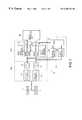
- FIG. 1is a block diagram of a preferred embodiment of a stereo camera adjusting system according to the present invention
- FIG. 2is a block diagram showing the detail of an image adjusting part (an affine transforming circuit) of FIG. 1;
- FIGS. 3A and 3Bare schematic diagrams showing the whole constructions of a stereo camera adjusting system according to the present invention.
- FIG. 4is a timing chart showing the image capturing timing and affine transforming timing in the image adjusting part of FIG. 1;
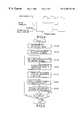
- FIG. 5is a flow chart of an image correcting routine in a correction operating part of FIG. 1;
- FIG. 6is a schematic diagram for explaining corresponding regions between a reference image and a comparative image
- FIG. 7is a schematic diagram for explaining an angle of rotation in the affine transformation of a comparative image
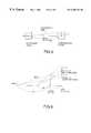
- FIG. 8is a schematic diagram for explaining the deviation of a horizontal line of a main camera from a base line.
- FIG. 9is a schematic diagram for explaining a camera system viewed from side.
- FIGS. 1 through 9show the preferred embodiment of the present invention.
- FIGS. 3A and 3Bare top and side views of a stereo camera, respectively.
- a stereo camera 1comprises two cameras 2 and 3 synchronized with each other.
- Each of the cameras 2 and 3is provided with an image sensor, such as a charge coupled device (CCD), therein and capable of changing the shutter speed thereof.
- One camera (first camera) 2serves as a main camera for picking up a reference image for a stereo processing
- the other camera (second camera) 3serves as a sub-camera for picking up a comparative image for the stereo processing.
- These cameras 2 and 3are provided on a stay 4 at-regular intervals.
- Two images picked up by the cameras 2 and 3are inputted to a stereo processing unit 40 via an image input unit 10 .
- the stereo processing unit 40the conformity of the two images with each other is estimated by the stereo matching to calculate a three-dimensional position of an object, to recognize an image of the object, and so forth.
- the two cameras 2 and 3are adjusted to be fixed on the stay 4 so that the optical axes thereof are parallel to each other at an initial manufacturing stage.
- the deviations of the optical axesare gradually caused in usual use, and the ranging accuracy is gradually lowered in the long run, so that errors can not disregarded finally.
- the image input unit 10 provided between the cameras 2 , 3 and the stereo processing unit 40has the function of adjusting the optical positions of the cameras 2 and 3 by an image correction, to automatically correct the deviations of images picked up by the cameras 2 and 3 to precisely and equivalently adjust the optical axes of the cameras 2 and 3 in a stage that the deviations of the optical axes of the cameras 2 and 3 are minor, i.e., in an early stage that mismatching is small during the stereo matching in the stereo processing unit 40 .
- FIG. 1the detail of the image input unit 10 of FIG. 3 will be described below.
- the image input unit 10comprises: an image input part 10 a for inputting a picked-up image; an image adjusting part 10 b for carrying out a geometrical transformation, such as rotation and parallel displacement of the image; and a correction operating part 10 c for calculating an transforming value for the image.
- the image input part 10 ahas analog interfaces 11 and 12 for adjusting analog images, which are outputted from the cameras 2 and 3 , to downstream input ranges, and A/D converters 13 and 14 for transforming the analog images into digital images having predetermined brightness and gradation (e.g., a gray scale of 256 gradations).
- predetermined brightness and gradatione.g., a gray scale of 256 gradations.
- the image adjusting part 10 bhas input image memories 15 and 16 for temporarily storing the digitized images, and affine transforming circuits 17 and 18 for carrying out a geometrical transformation, such as rotation and parallel displacement, of the digital images stored in the input image memories 15 and 16 to output the geometrically transformed images to the stereo processing unit 40 .
- affine transforming circuits 17 and 18for carrying out a geometrical transformation, such as rotation and parallel displacement, of the digital images stored in the input image memories 15 and 16 to output the geometrically transformed images to the stereo processing unit 40 .
- the affine transforming circuits 17 and 18carry out corrections when the corresponding points of the images picked up by the cameras 2 and 3 move geometrically from the original positions due to the deviations of the optical axes.
- the internal construction of the affine transforming circuits 17is shown in FIG. 2 .
- the affine transforming circuit 17comprises: an image memory data interface 20 for writing data into the input image memory 15 and for reading data out of the input image memory 15 ; an image memory address interface 21 for addressing the input image memory 15 ; an input image writing address generating circuit 22 for generating an address when the image data outputted from the A/D converter 13 are written in the input image memory 15 ; an inverse affine transformation reading address generating circuit 23 for generating an address, which is used for reading the image data out of the input image memory 15 to geometrically transform the image, by the inverse affine transformation; and an interpolation operating circuit 24 for carrying out the linear interpolation of data, which have been read by the inverse affine transformation, to output transformed image data.
- the original image before transformation and the transformed imageare digital images wherein pixels are arranged in the form of a grid, and the concentration values of the pixels on the transformed image are given by the concentration values of the corresponding pixel positions derived by the inverse affine transformation of the original image.
- the corresponding pixel positions derived by the inverse affine transformationare not generally integer pixel positions, so that the pixels on the transformed image do not correspond to any pixels on the original image. Therefore, the interpolation operating circuit 24 carries out the linear interpolation using the concentration values of four surrounding pixels, to closely derive the concentration values of the pixels on the transformed image.
- image signals outputted from the cameras 2 and 3e.g., image signals, such as NTSC picture signals, outputted from the cameras 2 and 3 in synchronism with a line synchronizing signal and a frame synchronizing signal, are sampled in a sampling period of a field signal, the affine transforming circuits 17 and 18 transform the sampled image in the next field interval.
- image signals outputted from the cameras 2 and 3e.g., image signals, such as NTSC picture signals, outputted from the cameras 2 and 3 in synchronism with a line synchronizing signal and a frame synchronizing signal
- the gain offset and so forth of image signals outputted from the cameras 2 and 3are adjusted to the input ranges of the A/D converters 13 and 14 by means of the analog interfaces 11 and 12 .
- the digital image data converted by the A/D converters 13 and 14are stored in the input image memories 15 and 16 in accordance with addresses generated by the input image writing address generating circuits 22 and 22 of the affine transforming circuits 17 and 18 .
- the concentration data at addresses generated by the inverse affine transformation reading address generating circuits 23 and 23 of the affine transforming circuits 17 and 18are read out of the input image memories 15 and 16 .
- the interpolation operations of the concentration dataare carried out by means of the interpolation operating circuits 24 and 24 of the affine transforming circuits 17 and 18 to output the transformed images to the stereo processing unit 40 .
- the correction values for the variations of optical axes of the cameras 2 and 3i.e., the image transforming values in the affine transforming circuit 17 and 18
- a special adjusting patternarranged at a known distance (a distance by which a parallax can be inversely calculated).
- the correction valuesare operated by the correction operating part 10 c to be fed to the affine transforming circuits 17 and 18 as the image transforming values to automatically make an adjustment.
- the correction operating part 10 ccomprises a computer having a CPU 31 , image memories 32 and 33 and so forth.
- the correction operating part 10 cis connected to the A/D converters 13 and 14 of the image input unit 10 via the image memories 32 and 33 , and to the stereo processing unit 40 . It is noted that the correction operating part 10 c may be a part of the stereo processing unit 40 and carry out the correction processing as a background job of the stereo image processing.
- FIG. 5is an image correcting routine executed by the CPU 31 of the correction operating part 10 c every a predetermined period.
- this routineat step S 100 , the results of a group filter, which are obtained when images of a landscape picked up by the cameras 2 and 3 are processed to extract three-dimensional object data from a distance image, are read out of the stereo processing unit 40 , and some small regions for operating correction values are set in the image picked up by the main camera 2 , i.e., in a reference image.
- each of the small regionsis a region of 16 ⁇ 16 pixels, the half or more of which include corresponding distance image data.
- the small regionsthree regions including two distant regions at a long distance of about 50 to 60 m and one near region at a short distance of up to about 5 m are selected.
- the two distant regionsare spaced from each other so as to have substantially the same distance data.
- the group filteris a software filter for detecting a group having an image deviation similar to those of surrounding pixels to efficiently remove noises included in the distance image.
- Such a group filteris disclosed in Japanese Patent Application No. 9-86877, which is assigned to the present Assignee and incorporated herein by reference.
- step S 110distance data (deviation) are added to the positions of the respective regions of the reference image set at step S 100 , to define a range for searching the corresponding regions in the image picked up by the sub-camera 3 , i.e., in the comparative image.
- this rangeis searched to derive the positions of the regions at a resolution of one pixel or less (e.g., a resolution of 1/10 pixels) by the sub-pixel processing.
- the position coordinates (Xc 1 , Yc 1 ) and (Xc 2 , Yc 2 ) of two distant regions # 1 C and # 2 C and the position coordinate (Xc 3 , Yc 3 ) of one near region # 3 C of the comparative imageare derived for the position coordinates (Xr 1 , Yr 1 ) and (Xr 2 , Yr 2 ) of two distant regions # 1 R and # 2 R and the position coordinate (Xr 3 , Yr 3 ) of one near region # 3 R of the reference image.
- a difference between the Y components of the position coordinates of one of the two distant regions on the reference image side and the corresponding distant region on the comparative image sidee.g., a difference (Yr 1 ⁇ Yc 1 ) between the Y components of the position coordinate (Xr 1 , Yr 1 ) of the left distant region # 1 R on the reference image side and the position coordinate (Xc 1 , Yc 1 ) of the corresponding left distant region # 1 C on the comparative image side in FIG.
- a Y direction translation correction valuei.e., as an image translating transformation value in Y directions, to parallel-displace the image (the comparative image) of the sub-camera 3 in Y directions.
- step S 140an X direction translation correction value for the comparative image is derived to be added to the set value of the affine transforming circuit 18 on the comparative image side to parallel-displace the image of the sub-camera 3 in X directions.
- This X direction translation correction valuecan be given by a deviation Z 0 between the reference and comparative images at infilty.
- the deviation Z 0 at infinitycan be represented by the following formula (1) using a distance d 1 to the distant region, a distance d 3 to the near region, a deviation Z 1 between the reference and comparative images in the distant region, and a deviation Z 3 between the reference and comparative images in the near region.
- ⁇ Z 0is a translation amount of the comparative image in lateral directions (X directions).
- the comparative imageis rotated so that the position of the Y coordinate of the other region of the comparative image is coincident with that of the reference image. That is, as shown in FIG. 7, the comparative image is rotated about the position coordinate (Xr 1 , Yr 1 ) of the left distant region # 1 R of the reference image so that the Y coordinate value Yc 2 of the right distant region # 2 C of the comparative image is coincident with the Y coordinate value Yr 2 of the right distant region # 2 R of the reference image.
- a coordinate (Xc 2 ′, Yc 2 ′) after rotationcan be represented by the following formula ( 2 ).
- ( Xc2 ′ Yc2 ′ )( cos ⁇ ⁇ ⁇ - sin ⁇ ⁇ ⁇ sin ⁇ ⁇ ⁇ cos ⁇ ⁇ ⁇ ) ⁇ ( Xc2 - Xr1 Yc2 - Yr2 ) + ( Xr1 Yr1 ) ( 2 )
- the angle of rotation ⁇can be derived by the following formula (6). Tis angle of rotation ⁇ is added to the set value of the affine transforming circuit 18 on the comparative image side as an image rotating transformation value about the coordinate (Xr 1 , Yr 1 ) to rotate the image (the comparative image) of the sub-camera 3 .
- the near region # 3 C of the comparative imageis also rotated.
- the base lines of the cameras 2 and 3are not parallel to the horizontal line of the main camera 2 so that the horizontal line of the main camera 2 is inclined by an angle ⁇ with respect to the base lines as shown in FIG. 8, there is a difference ⁇ Ym ⁇ Ys between the Y coordinate value Yr 3 of the near region # 3 R of the reference image and the Y coordinate value Yc 3 of the near region # 3 C of the comparative image after rotation as shown in FIG. 9 .
- the rotation by the angle of rotation ⁇ about the coordinate (Xr 1 , Yr 1 ) on the reference image sideis added to the set value in order to remove the difference ⁇ Ym ⁇ Ys.
- the angle of rotation ⁇can be derived from the base length B of the cameras 2 and 3 and a deviation ⁇ Y between the centers of the reference and comparative images on a focal plane.
- the deviation ⁇ Ycan be derived using the focal point f, the distance d 1 to the distant region, the distance d 3 to the near region and the difference ⁇ Ym ⁇ Ys on the basis of the geometrical relationship when the camera system is viewed from side as shown in FIG. 9 .
- the deviation ⁇ Ycan be derived by the following formula (7) using the difference ⁇ m ⁇ Ys between the deviation ⁇ Ym of the near region from the center of the reference image formed on the CCD surface (image picked-up surface) and the deviation ⁇ Ys of the near region from the center of the comparative image formed on the CCD surface. From the deviation ⁇ Y and the base length B, the angle of rotation ⁇ can be finally derived by the following formula (8)
- ⁇ Y( ⁇ Ym ⁇ Ys ) ⁇ d 1 ⁇ d 3 /( f ⁇ ( d 1 ⁇ d 3 )) (7)
- the routinegoes from the above step S 160 to step S 170 wherein it is examined whether the angles of rotation ⁇ and ⁇ are sufficiently small to be within a range of allowable values.
- the routinereturns to the step S 120 wherein the position of the corresponding region of the comparative image is determined by the sub-pixel processing again. Then, the same processing is repeated, and when the angles of rotation ⁇ and ⁇ are sufficiently small below the allowable value, the routine ends.
- the deviations of the optical axes of the cameras 2 and 3 gradually caused in usual usecan be automatically corrected while maintaining the operation state in the field.
Landscapes
- Engineering & Computer Science (AREA)
- Multimedia (AREA)
- Signal Processing (AREA)
- Measurement Of Optical Distance (AREA)
- Length Measuring Devices By Optical Means (AREA)
- Stereoscopic And Panoramic Photography (AREA)
- Studio Devices (AREA)
- Image Analysis (AREA)
- Image Input (AREA)
- Image Processing (AREA)
Abstract
Description
1. Field of the Invention
The present invention relates generally to a stereo camera system and method for adjusting the deviation of an optical axis of a stereo camera.
2. Related Background Art
As a three-dimensional measuring technique based on images, there is known an image processing based on a so-called stereo method for deriving a correlation between a pair of images, which are obtained by picking up an object from different positions by two cameras (a stereo camera), to derive a distance by a parallax for the same object on the basis of the principle of triangulation using camera parameters, such as the mounting position and focal length of the stereo camera.
In this image processing based on the stereo method, two picture signals obtained by the stereo camera are sequentially shifted to be superposed on each other to derive a position at which the two picture signals are coincident with each other. Therefore, it is desired that there are no deviations other than the parallax between the two picture signals, so that the optical positioning of the stereo camera is important.
Thus, Japanese Patent Laid-Open No. 5-157557 discloses that a holding member for connecting and holding a pair of video cameras has parallelism adjusting means for adjusting the arrangement of pixels of an image sensor of one of the video cameras so as to be parallel to the arrangement of pixels of an image sensor of the other video camera, and an optical axis adjusting member for adjusting the optical axis of one of the video cameras so as to be parallel to the optical axis of the other video camera, so that the correlation between the two cameras is mechanically adjusted and held.
However, even if the stereo camera is fixed once, the deviation of the stereo camera is easily caused with secular change. Conventionally, if such a deviation is caused, the stereo camera must be mechanically readjusted. Therefore, it is not only required to carry out the complicated operation, but it also takes a lot of time to readjust the stereo camera, so that there is a limit to the mechanical adjustment to ensure required accuracy.
In order to cope with this problem, Japanese Patent Application No. 9-117268, which is assigned to the present Assignee and incorporated herein by reference, discloses a technique for electrically adjusting the optical position of a stereo camera without the need of any mechanical adjustments. This technique can accurately adjust the optical position of a stereo camera to a level, at which it is difficult to mechanically adjust the optical position of the stereo camera, and easily readjust the deviation due to secular change after the adjustment.
However, since the technique disclosed in Japanese Patent Application No. 9-117268 is designed to pick up an image of a special adjusting pattern by means of a stereo camera to correct the optical position of the stereo camera, it is required to periodically stop the operation of the stereo camera in an image processing field to adjust the optical position of the stereo camera, so that it is required to care maintenance.
It is therefore an object of the present invention to eliminate the aforementioned problems and to provide a stereo camera adjusting system and method capable of automatically adjusting the age-based deviation of the optical axis of a stereo camera while maintaining the operating state thereof from an early stage, in which it is possible to disregard the influence on ranging accuracy.
In order to accomplish the aforementioned and other objects, according to one aspect of the present invention, there is provided a stereo camera adjusting system for adjusting an optical axis of a stereo camera having first and second cameras arranged at regular intervals, the system comprising: image adjusting means for geometrically transforming an image, which is picked up by the second camera, by a translation correction and a rotation correction, and for geometrically transforming an image, which is picked up by the first camera, by a rotation correction; and correction operating means for calculating a difference between corresponding positions of the images, which are picked up by the first and second cameras, on the basis of distance data obtained by stereo-processing the pair of images picked up by the first and second cameras, and for setting a transforming value for the image transformation so as to remove the difference.
The correction operating means may calculate the difference on the basis of two distant regions substantially at the same distance and one near region. The correction operating means may define a range including regions corresponding to the regions, in the image picked up by the second camera, on the basis of distance data of the distant regions of the image picked up by the first camera, and search the defined range to derive the distant regions of the image picked up by the second camera. The image adjusting means may geometrically transform the image, which is picked up by the second camera, by a horizontal translation correction and a vertical translation correction, and the correction operating means may calculate a transforming value for the image transformation based on the horizontal translation correction for the image picked up by the second camera, on the basis of a deviation between the positions of the regions of the images picked up by the first and second cameras, and distances of the regions. The correction operating means may set the transforming value for the image transformation on the basis of a pair of images of a landscape picked up by the first and second cameras.
According to another aspect of the present invention, there is provided a stereo camera adjusting method for adjusting an optical axis of a stereo camera having first and second cameras provided at regular intervals, the method comprising the steps of: calculating a difference between corresponding positions of images picked up by the first and second cameras, on the basis of distance data obtained by stereo-processing the pair of images picked up by the first and second cameras; setting a translation correction value and a rotation correction value for the second camera so as to remove the calculated difference; and geometrically transforming the image picked up by the second camera, by a translation correction and a rotation correction, on the basis of the set translation correction value and the set rotation correction value for the second camera.
The stereo camera adjusting method may further comprise the steps of: setting a rotation correction value for the first camera so as to remove the calculated difference; and geometrically transforming the image picked up by the first camera, by a rotation correction on the basis of the set rotation correction value for the first camera.
That is, according to the present invention, on the basis of distance data obtained by processing a pair of images of a landscape picked up by a stereo camera, a difference between corresponding positions of images picked up by first and second cameras is calculated. Then, an image transforming value for a rotation correction in the image picked up by the first camera, and image transforming values for a translation correction and a rotation correction in horizontal and vertical directions in the image picked up by the second camera are set so as to remove the difference. Then, the images picked up by the first and second cameras are geometrically transformed to automatically correct the age-based deviation of the optical axis of the stereo camera.
Thus, since the age-based deviation of the optical axis of the stereo camera is automatically adjusted while maintaining the operating state thereof from an early stage, in which it is possible to disregard the influence on ranging accuracy, it is possible to always use the stereo camera in an accurately adjusted state, and it is not required to stop the operation of the stereo camera in a field unlike the technique for picking up an image of a special adjusting pattern to adjust the optical position of the stereo camera, so that there are excellent advantages in that it is possible to achieve maintenance free.
The difference between the corresponding positions is preferably calculated on the basis of two distant regions, which are arranged substantially at the same distance, and one near region. Thus, it is possible to simultaneously carry out corrections for relative positions of the respective images and a correction for causing the horizontal line of the first camera to be parallel to the base line of the stereo camera.
In addition, the positions of the distant regions of the image picked up by the second camera may be obtained by adding distance data to the positions of the distant regions of the image picked up by the first camera, defining a range including corresponding regions, in the image picked up by the second camera, and searching the defined range. The horizontal translation correction for the image picked up by the second camera may be calculated on the basis of the deviations of the positions of the respective regions in the images picked up by the first and second cameras, and the distances of the respective regions.
A preferred embodiment of the present invention will become understood from the following detailed description referring to the accompanying drawings.
In the drawings:
FIG. 1 is a block diagram of a preferred embodiment of a stereo camera adjusting system according to the present invention;
FIG. 2 is a block diagram showing the detail of an image adjusting part (an affine transforming circuit) of FIG. 1;
FIGS. 3A and 3B are schematic diagrams showing the whole constructions of a stereo camera adjusting system according to the present invention;
FIG. 4 is a timing chart showing the image capturing timing and affine transforming timing in the image adjusting part of FIG. 1;
FIG. 5 is a flow chart of an image correcting routine in a correction operating part of FIG. 1;
FIG. 6 is a schematic diagram for explaining corresponding regions between a reference image and a comparative image;
FIG. 7 is a schematic diagram for explaining an angle of rotation in the affine transformation of a comparative image;
FIG. 8 is a schematic diagram for explaining the deviation of a horizontal line of a main camera from a base line; and
FIG. 9 is a schematic diagram for explaining a camera system viewed from side.
Referring now to the accompanying drawings, the preferred embodiment of the present invention will be described below. FIGS. 1 through 9 show the preferred embodiment of the present invention.
First, referring to FIGS. 3A and 3B, the whole construction of the preferred embodiment of the present invention will be described. Furthermore, FIGS. 3A and 3B are top and side views of a stereo camera, respectively. In FIGS. 3A and 3B, astereo camera 1 comprises twocameras cameras cameras stay 4 at-regular intervals.
Two images picked up by thecameras stereo processing unit 40 via animage input unit 10. In thestereo processing unit 40, the conformity of the two images with each other is estimated by the stereo matching to calculate a three-dimensional position of an object, to recognize an image of the object, and so forth. In this case, the twocameras stay 4 so that the optical axes thereof are parallel to each other at an initial manufacturing stage. However, there are the possibilities that the deviations of the optical axes are gradually caused in usual use, and the ranging accuracy is gradually lowered in the long run, so that errors can not disregarded finally.
For that reason, theimage input unit 10 provided between thecameras stereo processing unit 40 has the function of adjusting the optical positions of thecameras cameras cameras cameras stereo processing unit 40.
Referring now to FIG. 1, the detail of theimage input unit 10 of FIG. 3 will be described below.
As shown in FIG. 1, theimage input unit 10 comprises: animage input part 10afor inputting a picked-up image; animage adjusting part 10bfor carrying out a geometrical transformation, such as rotation and parallel displacement of the image; and acorrection operating part 10cfor calculating an transforming value for the image.
Theimage input part 10ahasanalog interfaces cameras D converters
Theimage adjusting part 10bhasinput image memories affine transforming circuits input image memories stereo processing unit 40.
Theaffine transforming circuits cameras affine transforming circuits affine transforming circuits 17 is shown in FIG.2.
Theaffine transforming circuit 17 comprises: an imagememory data interface 20 for writing data into theinput image memory 15 and for reading data out of theinput image memory 15; an imagememory address interface 21 for addressing theinput image memory 15; an input image writingaddress generating circuit 22 for generating an address when the image data outputted from the A/D converter 13 are written in theinput image memory 15; an inverse affine transformation readingaddress generating circuit 23 for generating an address, which is used for reading the image data out of theinput image memory 15 to geometrically transform the image, by the inverse affine transformation; and aninterpolation operating circuit 24 for carrying out the linear interpolation of data, which have been read by the inverse affine transformation, to output transformed image data.
That is, in the geometrical transformation of the image using theaffine transforming circuits interpolation operating circuit 24 carries out the linear interpolation using the concentration values of four surrounding pixels, to closely derive the concentration values of the pixels on the transformed image.
As shown in FIG. 4, when image signals outputted from thecameras cameras affine transforming circuits
That is, the gain offset and so forth of image signals outputted from thecameras D converters D converters input image memories address generating circuits affine transforming circuits address generating circuits affine transforming circuits input image memories interpolation operating circuits affine transforming circuits stereo processing unit 40.
The correction values for the variations of optical axes of thecameras affine transforming circuit correction operating part 10cto be fed to theaffine transforming circuits
Thecorrection operating part 10ccomprises a computer having aCPU 31,image memories correction operating part 10cis connected to the A/D converters image input unit 10 via theimage memories stereo processing unit 40. It is noted that thecorrection operating part 10cmay be a part of thestereo processing unit 40 and carry out the correction processing as a background job of the stereo image processing.
Referring to a flow chart of FIG. 5, the image correction carried out by theimage adjusting part 10band thecorrection operating part 10cwill be described below.
FIG. 5 is an image correcting routine executed by theCPU 31 of thecorrection operating part 10cevery a predetermined period. In this routine, at step S100, the results of a group filter, which are obtained when images of a landscape picked up by thecameras stereo processing unit 40, and some small regions for operating correction values are set in the image picked up by themain camera 2, i.e., in a reference image.
For example, it is assumed that each of the small regions is a region of 16×16 pixels, the half or more of which include corresponding distance image data. As the small regions, three regions including two distant regions at a long distance of about 50 to 60 m and one near region at a short distance of up to about 5 m are selected. The two distant regions are spaced from each other so as to have substantially the same distance data. Furthermore, the group filter is a software filter for detecting a group having an image deviation similar to those of surrounding pixels to efficiently remove noises included in the distance image. Such a group filter is disclosed in Japanese Patent Application No. 9-86877, which is assigned to the present Assignee and incorporated herein by reference.
Then, the routine goes to step S110 wherein distance data (deviation) are added to the positions of the respective regions of the reference image set at step S100, to define a range for searching the corresponding regions in the image picked up by thesub-camera 3, i.e., in the comparative image. Then, at step S120, this range is searched to derive the positions of the regions at a resolution of one pixel or less (e.g., a resolution of 1/10 pixels) by the sub-pixel processing.
As a result, as shown in FIG. 6, in a coordinate system wherein the origin is arranged at a left-upper comer of an image and X and Y coordinates are arranged in horizontal and vertical directions, the position coordinates (Xc1, Yc1) and (Xc2, Yc2) of two distant regions #1C and #2C and the position coordinate (Xc3, Yc3) of one nearregion # 3C of the comparative image are derived for the position coordinates (Xr1, Yr1) and (Xr2, Yr2) of two distant regions #1R and #2R and the position coordinate (Xr3, Yr3) of one nearregion # 3R of the reference image.
Subsequently, at step S130, a difference between the Y components of the position coordinates of one of the two distant regions on the reference image side and the corresponding distant region on the comparative image side, e.g., a difference (Yr1−Yc1) between the Y components of the position coordinate (Xr1, Yr1) of the leftdistant region # 1R on the reference image side and the position coordinate (Xc1, Yc1) of the corresponding left distant region #1C on the comparative image side in FIG. 6, is derived to be added to the set value of theaffine transforming circuit 18 on the comparative image side as a Y direction translation correction value, i.e., as an image translating transformation value in Y directions, to parallel-displace the image (the comparative image) of the sub-camera3 in Y directions.
Then, the routine goes to step S140 wherein an X direction translation correction value for the comparative image is derived to be added to the set value of theaffine transforming circuit 18 on the comparative image side to parallel-displace the image of the sub-camera3 in X directions. This X direction translation correction value can be given by a deviation Z0 between the reference and comparative images at infilty. The deviation Z0 at infinity can be represented by the following formula (1) using a distance d1 to the distant region, a distance d3 to the near region, a deviation Z1 between the reference and comparative images in the distant region, and a deviation Z3 between the reference and comparative images in the near region. Thus, it is assumed that −Z0 is a translation amount of the comparative image in lateral directions (X directions).
Originally, at the corresponding points of the reference and comparative images, only X coordinates in horizontal directions must be different to detect a parallax, and Y coordinates must be the same. Therefore, at the above step S130, the positions of the Y coordinates of one of the two distant regions in the reference and comparative images are caused to be coincident wit each other, and at the above step S140, the position of the X coordinate in the reference image is adjusted to a position, at which the original parallax is to be detected.
Then, at step S150, the comparative image is rotated so that the position of the Y coordinate of the other region of the comparative image is coincident with that of the reference image. That is, as shown in FIG. 7, the comparative image is rotated about the position coordinate (Xr1, Yr1) of the leftdistant region # 1R of the reference image so that the Y coordinate value Yc2 of the right distant region #2C of the comparative image is coincident with the Y coordinate value Yr2 of the rightdistant region # 2R of the reference image. When the coordinate (Xc2, Yc2) is rotated about the coordinate (Xr1, Yr1) by an angle of rotation θ, a coordinate (Xc2′, Yc2′) after rotation can be represented by the following formula (2).

If the Y coordinate value Yc2′ of the region #2C of the comparative image after rotation is coincident with the Y coordinate value Yr2 of theregion # 2R of the reference image, and the above formula (2) is rearranged with respect to only Y components assuming that Yc2′=Yr2, the following formula (3) can be obtained.
Moreover, if Yr2−Yr1=A, Xc2−Xr1=B, Yc2−Yr1=C, and cos θ=±(1−sin2θ)½ are substituted for the above formula (3) to solve the formula (3) with respect to sin θ, the following formula (4) can be obtained.
When Yr2=Yc2 and A=C, i.e., when the Y coordinate value of the rightdistant region # 2R of the reference image has been coincident with the Y coordinate value of the right distant region #2C of the comparative image, the above formula (4) is 0 since rotation is not required. In this case, it can be seen from the following formula (5) that the sign of the second term of the numerator of the above formula (4) must be negative.
Therefore, the angle of rotation θ can be derived by the following formula (6). Tis angle of rotation θ is added to the set value of theaffine transforming circuit 18 on the comparative image side as an image rotating transformation value about the coordinate (Xr1, Yr1) to rotate the image (the comparative image) of thesub-camera 3.
By this rotation of the comparative image, thenear region # 3C of the comparative image is also rotated. When the base lines of thecameras main camera 2 so that the horizontal line of themain camera 2 is inclined by an angle φ with respect to the base lines as shown in FIG. 8, there is a difference ΔYm−ΔYs between the Y coordinate value Yr3 of thenear region # 3R of the reference image and the Y coordinate value Yc3 of thenear region # 3C of the comparative image after rotation as shown in FIG.9.
Therefore, at the next step S160, the rotation by the angle of rotation φ about the coordinate (Xr1, Yr1) on the reference image side is added to the set value in order to remove the difference ΔYm−ΔYs. As can be seen clearly from FIG. 8, the angle of rotation φ can be derived from the base length B of thecameras
That is, the deviation ΔY can be derived by the following formula (7) using the difference Δm−ΔYs between the deviation ΔYm of the near region from the center of the reference image formed on the CCD surface (image picked-up surface) and the deviation ΔYs of the near region from the center of the comparative image formed on the CCD surface. From the deviation ΔY and the base length B, the angle of rotation φ can be finally derived by the following formula (8)

When the comparative and reference images are rotated in the above manner, the routine goes from the above step S160 to step S170 wherein it is examined whether the angles of rotation θ and φ are sufficiently small to be within a range of allowable values. When the angles of rotation θ and φ have not reached the allowable values, the routine returns to the step S120 wherein the position of the corresponding region of the comparative image is determined by the sub-pixel processing again. Then, the same processing is repeated, and when the angles of rotation θ and φ are sufficiently small below the allowable value, the routine ends.
Thus, the deviations of the optical axes of thecameras
While the presently preferred embodiment of the present invention has been shown and described, it is to be understood that this disclosure is for the purpose of illustration and that various changes and modifications may be made without departing from the scope of the invention as set forth in the appended claims.
Claims (6)
1. A stereo camera adjusting system for adjusting an optical axis of a stereo camera having first and second cameras arranged at regular intervals, comprising:
image adjusting means for geometrically transforming one of a first image picked up by said first camera and a second image picked up by said second camera by a translation correction value and a rotation correction value; and
correction operating means for calculating said translation correction value and said rotation correction value based on coordinate differences of a plurality of corresponding positions between said first image and said second image, wherein said corresponding positions include at least a position at long range from said stereo camera and a position at short range near said stereo camera.
2. The stereo camera adjusting system as set forth inclaim 1 , wherein said correction operating means calculates a vertical direction translation correction value based on a deviation of coordinates between said first image and said second image at said corresponding positions at long range and then calculates a horizontal direction translation correction value given by a deviation at infinity between said first image and said second image based on distances to said corresponding positions at long range and short range.
3. The stereo camera adjusting system as set forth inclaim 2 , wherein said correction operating means further calculates said rotation correction value based on coordinate differences of two corresponding positions at long range and one corresponding position at short range between said first image and said second image.
4. The stereo camera adjusting system as set forth inclaim 1 , wherein said image adjusting means is an affine transforming circuit.
5. A stereo camera adjusting method for adjusting an optical axis of a stereo camera having first and second cameras arranged at regular intervals and a transforming circuit having image transforming values for transforming first and second images picked up by said first and second cameras, respectively, comprising:
calculating a translation correction value and a rotation correction value based on coordinate differences of a plurality of corresponding positions between said first and second images, said corresponding positions include at least a position at long range from said stereo camera and a position at short range near said stereo camera; and
correcting said image transforming values by said translation correction value and said rotation correction value.
6. The stereo camera adjusting method as set forth inclaim 5 , wherein said calculating further comprises:
calculating a vertical direction translation correction value based on a deviation of coordinates between said first and second images at said corresponding positions at long range;
calculating a horizontal direction translation correction value given by a deviation at infinity between said first and second images based on distances to said corresponding positions at long range and short range; and
calculating said rotation correction value based on coordinate differences of two corresponding positions at long range and one corresponding position at short range between said first and second images.
Applications Claiming Priority (2)
| Application Number | Priority Date | Filing Date | Title |
|---|---|---|---|
| JP06157798AJP4172554B2 (en) | 1998-03-12 | 1998-03-12 | Stereo camera adjustment device |
| JP10-061577 | 1998-03-12 |
Publications (1)
| Publication Number | Publication Date |
|---|---|
| US6385334B1true US6385334B1 (en) | 2002-05-07 |
Family
ID=13175130
Family Applications (1)
| Application Number | Title | Priority Date | Filing Date |
|---|---|---|---|
| US09/265,379Expired - LifetimeUS6385334B1 (en) | 1998-03-12 | 1999-03-10 | System and method for adjusting stereo camera |
Country Status (4)
| Country | Link |
|---|---|
| US (1) | US6385334B1 (en) |
| EP (1) | EP0942610B1 (en) |
| JP (1) | JP4172554B2 (en) |
| DE (1) | DE69918347T2 (en) |
Cited By (39)
| Publication number | Priority date | Publication date | Assignee | Title |
|---|---|---|---|---|
| US20030185421A1 (en)* | 2002-03-28 | 2003-10-02 | Kabushiki Kaisha Toshiba | Image processing apparatus and method |
| US20050089212A1 (en)* | 2002-03-27 | 2005-04-28 | Sanyo Electric Co., Ltd. | Method and apparatus for processing three-dimensional images |
| US20050286760A1 (en)* | 2004-06-23 | 2005-12-29 | Kabushiki Kaisha Topcon | Method for associating stereo image and three-dimensional data preparation system |
| US6985619B1 (en)* | 1999-09-22 | 2006-01-10 | Fuji Jukogyo Kabushiki Kaisha | Distance correcting apparatus of surroundings monitoring system and vanishing point correcting apparatus thereof |
| US20060013438A1 (en)* | 2004-07-13 | 2006-01-19 | Susumu Kubota | Obstacle detection apparatus and a method therefor |
| US20060115117A1 (en)* | 2004-11-30 | 2006-06-01 | Honda Motor Co. Ltd. | Position detecting apparatus and method of correcting data therein |
| US20060114320A1 (en)* | 2004-11-30 | 2006-06-01 | Honda Motor Co. Ltd. | Position detecting apparatus and method of correcting data therein |
| US20060115126A1 (en)* | 2004-11-30 | 2006-06-01 | Honda Motor Co., Ltd. | Vehicle vicinity monitoring apparatus |
| US20060115163A1 (en)* | 2004-11-30 | 2006-06-01 | Honda Motor Co., Ltd. | Apparatus for and method of extracting image |
| US20060204037A1 (en)* | 2004-11-30 | 2006-09-14 | Honda Motor Co., Ltd. | Vehicle vicinity monitoring apparatus |
| US7190389B1 (en)* | 1999-07-07 | 2007-03-13 | Pentax Corporation | Stereo camera |
| US7248287B1 (en)* | 1999-09-22 | 2007-07-24 | Fuji Jukagyo Kabushiki Kaisha | Method for examining shooting direction of camera apparatus, device thereof and structure for installing sensor |
| US20070248260A1 (en)* | 2006-04-20 | 2007-10-25 | Nokia Corporation | Supporting a 3D presentation |
| US20080049100A1 (en)* | 2006-08-24 | 2008-02-28 | Real D | Algorithmic interaxial reduction |
| US20090046924A1 (en)* | 2007-06-28 | 2009-02-19 | Noboru Morimitsu | Stereo-image processing apparatus |
| US20090187308A1 (en)* | 2008-01-18 | 2009-07-23 | Noboru Morimitsu | Vehicle Surroundings Monitoring Apparatus |
| US7685521B1 (en)* | 1999-03-23 | 2010-03-23 | Canon Kabushiki Kaisha | Information searching apparatus, method and memory medium therefor |
| US20110025825A1 (en)* | 2009-07-31 | 2011-02-03 | 3Dmedia Corporation | Methods, systems, and computer-readable storage media for creating three-dimensional (3d) images of a scene |
| US20110025830A1 (en)* | 2009-07-31 | 2011-02-03 | 3Dmedia Corporation | Methods, systems, and computer-readable storage media for generating stereoscopic content via depth map creation |
| US20110211751A1 (en)* | 2010-02-26 | 2011-09-01 | Sony Corporation | Method and apparatus for determining misalignment |
| US20110292182A1 (en)* | 2010-05-27 | 2011-12-01 | Kabushiki Kaisha Toshiba | Camera module and image recording method |
| US8274552B2 (en) | 2010-12-27 | 2012-09-25 | 3Dmedia Corporation | Primary and auxiliary image capture devices for image processing and related methods |
| US20120274627A1 (en)* | 2011-04-27 | 2012-11-01 | Aptina Imaging Corporation | Self calibrating stereo camera |
| US20130088579A1 (en)* | 2010-06-16 | 2013-04-11 | Cinetools Co., Ltd. | Device for optical axis alignment for image capturing |
| US8630755B2 (en) | 2010-09-28 | 2014-01-14 | Kabushiki Kaisha Topcon | Automatic taking-off and landing system |
| US8666571B2 (en) | 2011-01-04 | 2014-03-04 | Kabushiki Kaisha Topcon | Flight control system for flying object |
| JP2014072592A (en)* | 2012-09-28 | 2014-04-21 | Hitachi Automotive Systems Ltd | Image pick-up device |
| US9020666B2 (en) | 2011-04-28 | 2015-04-28 | Kabushiki Kaisha Topcon | Taking-off and landing target instrument and automatic taking-off and landing system |
| US20150271474A1 (en)* | 2014-03-21 | 2015-09-24 | Omron Corporation | Method and Apparatus for Detecting and Mitigating Mechanical Misalignments in an Optical System |
| US9185388B2 (en) | 2010-11-03 | 2015-11-10 | 3Dmedia Corporation | Methods, systems, and computer program products for creating three-dimensional video sequences |
| US9344701B2 (en) | 2010-07-23 | 2016-05-17 | 3Dmedia Corporation | Methods, systems, and computer-readable storage media for identifying a rough depth map in a scene and for determining a stereo-base distance for three-dimensional (3D) content creation |
| US9380292B2 (en) | 2009-07-31 | 2016-06-28 | 3Dmedia Corporation | Methods, systems, and computer-readable storage media for generating three-dimensional (3D) images of a scene |
| US9544575B2 (en) | 2011-09-28 | 2017-01-10 | Kabushiki Kaisha Topcon | Image acquiring device and image acquiring system |
| US20180139388A1 (en)* | 2016-03-30 | 2018-05-17 | Shanghai Bizhi Bionic Technology Co., Ltd | Image processing method and system for vision system |
| US10007998B2 (en) | 2015-03-20 | 2018-06-26 | Ricoh Company, Ltd. | Image processor, apparatus, and control system for correction of stereo images |
| US10200671B2 (en) | 2010-12-27 | 2019-02-05 | 3Dmedia Corporation | Primary and auxiliary image capture devices for image processing and related methods |
| US10539412B2 (en) | 2014-07-31 | 2020-01-21 | Hewlett-Packard Development Company, L.P. | Measuring and correcting optical misalignment |
| US10580163B2 (en)* | 2016-08-19 | 2020-03-03 | SCREEN Holdings Co., Ltd. | Displacement detecting apparatus, displacement detecting method and substrate processing apparatus |
| US10796425B1 (en)* | 2016-09-06 | 2020-10-06 | Amazon Technologies, Inc. | Imagery-based member deformation gauge |
Families Citing this family (24)
| Publication number | Priority date | Publication date | Assignee | Title |
|---|---|---|---|---|
| JP3280001B2 (en)* | 1999-09-16 | 2002-04-30 | 富士重工業株式会社 | Stereo image misalignment adjustment device |
| JP3263931B2 (en)* | 1999-09-22 | 2002-03-11 | 富士重工業株式会社 | Stereo matching device |
| JP3349121B2 (en) | 1999-09-22 | 2002-11-20 | 富士重工業株式会社 | Stereo camera mounting structure |
| DE10151417A1 (en)* | 2001-10-18 | 2003-05-08 | Siemens Ag | System and method for processing image data |
| DE10156535C1 (en) | 2001-11-14 | 2003-06-26 | Siemens Ag | breakers |
| US20040070667A1 (en)* | 2002-10-10 | 2004-04-15 | Fuji Photo Optical Co., Ltd. | Electronic stereoscopic imaging system |
| JP4828274B2 (en)* | 2006-03-27 | 2011-11-30 | 株式会社エヌ・ティ・ティ・データ | Structure abnormality determination system, structure abnormality determination method, and program |
| JP2008040115A (en)* | 2006-08-04 | 2008-02-21 | Fuji Heavy Ind Ltd | Stereo camera |
| JP4867837B2 (en)* | 2007-07-30 | 2012-02-01 | 株式会社島津製作所 | Motion tracker device |
| JP5031494B2 (en)* | 2007-09-07 | 2012-09-19 | 株式会社 ニコンビジョン | Telescope system |
| GB2473247B (en)* | 2009-09-04 | 2015-02-11 | Sony Corp | A method and apparatus for image alignment |
| GB2477333B (en)* | 2010-01-29 | 2014-12-03 | Sony Corp | A method and apparatus for creating a stereoscopic image |
| JP5444065B2 (en)* | 2010-03-19 | 2014-03-19 | 富士フイルム株式会社 | Compound eye imaging apparatus and control method thereof |
| JP5682265B2 (en)* | 2010-12-01 | 2015-03-11 | 株式会社リコー | Ranging device and imaging device |
| FR2972061B1 (en)* | 2011-02-24 | 2013-11-15 | Mobiclip | METHOD OF CALIBRATING A STEREOSCOPIC VIEWING DEVICE |
| JP5672112B2 (en)* | 2011-03-30 | 2015-02-18 | 富士通株式会社 | Stereo image calibration method, stereo image calibration apparatus, and computer program for stereo image calibration |
| JP5718149B2 (en)* | 2011-05-19 | 2015-05-13 | シャープ株式会社 | Image correction method and stereoscopic image photographing apparatus |
| JP2012022716A (en)* | 2011-10-21 | 2012-02-02 | Fujifilm Corp | Apparatus, method and program for processing three-dimensional image, and three-dimensional imaging apparatus |
| EP2757524B1 (en)* | 2013-01-16 | 2018-12-19 | Honda Research Institute Europe GmbH | Depth sensing method and system for autonomous vehicles |
| JP6521796B2 (en)* | 2015-08-26 | 2019-05-29 | 株式会社Subaru | Stereo image processing device |
| US20180091797A1 (en)* | 2016-09-27 | 2018-03-29 | The Boeing Company | Apparatus and method of compensating for relative motion of at least two aircraft-mounted cameras |
| KR101973655B1 (en)* | 2018-03-05 | 2019-08-26 | 주식회사 디아이블 | Method and apparatus for automatic identification of sports court and subsequent in/out determination |
| JP7109386B2 (en)* | 2019-01-22 | 2022-07-29 | 日立Astemo株式会社 | Image processing device |
| WO2025134302A1 (en)* | 2023-12-21 | 2025-06-26 | Astemo株式会社 | Image processing apparatus |
Citations (6)
| Publication number | Priority date | Publication date | Assignee | Title |
|---|---|---|---|---|
| JPH05157557A (en) | 1991-12-09 | 1993-06-22 | Mitsubishi Electric Corp | Onboard distance detector |
| US5699444A (en)* | 1995-03-31 | 1997-12-16 | Synthonics Incorporated | Methods and apparatus for using image data to determine camera location and orientation |
| US5748199A (en)* | 1995-12-20 | 1998-05-05 | Synthonics Incorporated | Method and apparatus for converting a two dimensional motion picture into a three dimensional motion picture |
| JPH10307352A (en) | 1997-05-07 | 1998-11-17 | Fuji Heavy Ind Ltd | Adjustment device for stereoscopic camera |
| US6028954A (en)* | 1988-11-18 | 2000-02-22 | Industrial Science & Technology, Kozo Iizuka, Director-General Of Agency | Method and apparatus for three-dimensional position measurement |
| US6031941A (en)* | 1995-12-27 | 2000-02-29 | Canon Kabushiki Kaisha | Three-dimensional model data forming apparatus |
Family Cites Families (5)
| Publication number | Priority date | Publication date | Assignee | Title |
|---|---|---|---|---|
| DE69417824T4 (en)* | 1993-08-26 | 2000-06-29 | Matsushita Electric Industrial Co., Ltd. | Stereoscopic scanner |
| JPH0814861A (en)* | 1994-07-01 | 1996-01-19 | Canon Inc | Measuring method and device for three-dimensional shape |
| JP3103478B2 (en)* | 1994-06-02 | 2000-10-30 | キヤノン株式会社 | Compound eye imaging device |
| JPH0843055A (en)* | 1994-07-29 | 1996-02-16 | Canon Inc | Three-dimensional object shape recognition method and device |
| US6118475A (en)* | 1994-06-02 | 2000-09-12 | Canon Kabushiki Kaisha | Multi-eye image pickup apparatus, and method and apparatus for measuring or recognizing three-dimensional shape |
- 1998
- 1998-03-12JPJP06157798Apatent/JP4172554B2/ennot_activeExpired - Lifetime
- 1999
- 1999-03-10USUS09/265,379patent/US6385334B1/ennot_activeExpired - Lifetime
- 1999-03-11EPEP99104888Apatent/EP0942610B1/ennot_activeExpired - Lifetime
- 1999-03-11DEDE69918347Tpatent/DE69918347T2/ennot_activeExpired - Lifetime
Patent Citations (6)
| Publication number | Priority date | Publication date | Assignee | Title |
|---|---|---|---|---|
| US6028954A (en)* | 1988-11-18 | 2000-02-22 | Industrial Science & Technology, Kozo Iizuka, Director-General Of Agency | Method and apparatus for three-dimensional position measurement |
| JPH05157557A (en) | 1991-12-09 | 1993-06-22 | Mitsubishi Electric Corp | Onboard distance detector |
| US5699444A (en)* | 1995-03-31 | 1997-12-16 | Synthonics Incorporated | Methods and apparatus for using image data to determine camera location and orientation |
| US5748199A (en)* | 1995-12-20 | 1998-05-05 | Synthonics Incorporated | Method and apparatus for converting a two dimensional motion picture into a three dimensional motion picture |
| US6031941A (en)* | 1995-12-27 | 2000-02-29 | Canon Kabushiki Kaisha | Three-dimensional model data forming apparatus |
| JPH10307352A (en) | 1997-05-07 | 1998-11-17 | Fuji Heavy Ind Ltd | Adjustment device for stereoscopic camera |
Cited By (81)
| Publication number | Priority date | Publication date | Assignee | Title |
|---|---|---|---|---|
| US7685521B1 (en)* | 1999-03-23 | 2010-03-23 | Canon Kabushiki Kaisha | Information searching apparatus, method and memory medium therefor |
| US7190389B1 (en)* | 1999-07-07 | 2007-03-13 | Pentax Corporation | Stereo camera |
| US7800688B2 (en) | 1999-09-22 | 2010-09-21 | Fuji Jukogyo Kabushiki Kaisha | Method for examining shooting direction of camera apparatus, device thereof and structure for installing sensor |
| US6985619B1 (en)* | 1999-09-22 | 2006-01-10 | Fuji Jukogyo Kabushiki Kaisha | Distance correcting apparatus of surroundings monitoring system and vanishing point correcting apparatus thereof |
| US20100302370A1 (en)* | 1999-09-22 | 2010-12-02 | Fuji Jukogyo Kabushiki Kaisha | Method for examining shooting direction of camera apparatus, device thereof and structure for installing sensor |
| US8508657B2 (en)* | 1999-09-22 | 2013-08-13 | Fuji Jukogyo Kabushiki Kaisha | Method for examining shooting direction of camera apparatus, device thereof and structure for installing sensor |
| US7248287B1 (en)* | 1999-09-22 | 2007-07-24 | Fuji Jukagyo Kabushiki Kaisha | Method for examining shooting direction of camera apparatus, device thereof and structure for installing sensor |
| US8724886B2 (en) | 2002-03-27 | 2014-05-13 | Sanyo Electric Co., Ltd. | Method and apparatus for processing three-dimensional images |
| US8577127B2 (en) | 2002-03-27 | 2013-11-05 | Sanyo Electric Co., Ltd. | Method and apparatus for processing three-dimensional images |
| US8559703B2 (en) | 2002-03-27 | 2013-10-15 | Sanyo Electric Co., Ltd. | Method and apparatus for processing three-dimensional images |
| US20050089212A1 (en)* | 2002-03-27 | 2005-04-28 | Sanyo Electric Co., Ltd. | Method and apparatus for processing three-dimensional images |
| US8577128B2 (en) | 2002-03-27 | 2013-11-05 | Sanyo Electric Co., Ltd. | Method and apparatus for processing three-dimensional images |
| US20110103680A1 (en)* | 2002-03-27 | 2011-05-05 | Sanyo Electric Co., Ltd. | Method and apparatus for processing three-dimensional images |
| US8879824B2 (en) | 2002-03-27 | 2014-11-04 | Sanyo Electric Co., Ltd. | Method and apparatus for processing three-dimensional images |
| US8472702B2 (en) | 2002-03-27 | 2013-06-25 | Sanyo Electric Co., Ltd. | Method and apparatus for processing three-dimensional images |
| US8417024B2 (en) | 2002-03-27 | 2013-04-09 | Sanyo Electric Co., Ltd. | Method and apparatus for processing three-dimensional images |
| US8369607B2 (en)* | 2002-03-27 | 2013-02-05 | Sanyo Electric Co., Ltd. | Method and apparatus for processing three-dimensional images |
| US8254668B2 (en) | 2002-03-27 | 2012-08-28 | Sanyo Electric Co., Ltd. | Method and apparatus for processing three-dimensional images |
| US8131064B2 (en) | 2002-03-27 | 2012-03-06 | Sanyo Electric Co., Ltd. | Method and apparatus for processing three-dimensional images |
| US20110157174A1 (en)* | 2002-03-27 | 2011-06-30 | Sanyo Electric Co., Ltd. | Method and apparatus for processing three-dimensional images |
| US20030185421A1 (en)* | 2002-03-28 | 2003-10-02 | Kabushiki Kaisha Toshiba | Image processing apparatus and method |
| US7149327B2 (en)* | 2002-03-28 | 2006-12-12 | Kabushiki Kaisha Toshiba | Image processing apparatus and method |
| US7804996B2 (en)* | 2004-06-23 | 2010-09-28 | Kabushiki Kaisha Topcon | Method for associating stereo image and three-dimensional data preparation system |
| US20050286760A1 (en)* | 2004-06-23 | 2005-12-29 | Kabushiki Kaisha Topcon | Method for associating stereo image and three-dimensional data preparation system |
| US20060013438A1 (en)* | 2004-07-13 | 2006-01-19 | Susumu Kubota | Obstacle detection apparatus and a method therefor |
| US7599521B2 (en) | 2004-11-30 | 2009-10-06 | Honda Motor Co., Ltd. | Vehicle vicinity monitoring apparatus |
| US7567688B2 (en)* | 2004-11-30 | 2009-07-28 | Honda Motor Co., Ltd. | Apparatus for and method of extracting image |
| US20060204037A1 (en)* | 2004-11-30 | 2006-09-14 | Honda Motor Co., Ltd. | Vehicle vicinity monitoring apparatus |
| US20060114320A1 (en)* | 2004-11-30 | 2006-06-01 | Honda Motor Co. Ltd. | Position detecting apparatus and method of correcting data therein |
| US20060115117A1 (en)* | 2004-11-30 | 2006-06-01 | Honda Motor Co. Ltd. | Position detecting apparatus and method of correcting data therein |
| US7616806B2 (en) | 2004-11-30 | 2009-11-10 | Honda Motor Co., Ltd. | Position detecting apparatus and method of correcting data therein |
| US7590263B2 (en) | 2004-11-30 | 2009-09-15 | Honda Motor Co., Ltd. | Vehicle vicinity monitoring apparatus |
| US7620237B2 (en)* | 2004-11-30 | 2009-11-17 | Honda Motor Co., Ltd. | Position detecting apparatus and method of correcting data therein |
| US20060115126A1 (en)* | 2004-11-30 | 2006-06-01 | Honda Motor Co., Ltd. | Vehicle vicinity monitoring apparatus |
| US20060115163A1 (en)* | 2004-11-30 | 2006-06-01 | Honda Motor Co., Ltd. | Apparatus for and method of extracting image |
| US20070248260A1 (en)* | 2006-04-20 | 2007-10-25 | Nokia Corporation | Supporting a 3D presentation |
| US20080049100A1 (en)* | 2006-08-24 | 2008-02-28 | Real D | Algorithmic interaxial reduction |
| US8736672B2 (en)* | 2006-08-24 | 2014-05-27 | Reald Inc. | Algorithmic interaxial reduction |
| WO2008024316A3 (en)* | 2006-08-24 | 2008-10-16 | Real D | Algorithmic interaxial reduction |
| US20090046924A1 (en)* | 2007-06-28 | 2009-02-19 | Noboru Morimitsu | Stereo-image processing apparatus |
| US8417022B2 (en)* | 2007-06-28 | 2013-04-09 | Fuji Jukogyo Kabushiki Kaisha | Stereo-image processing apparatus |
| US8160301B2 (en)* | 2008-01-18 | 2012-04-17 | Fuji Jukogyo Kabushiki Kaisha | Vehicle surroundings monitoring apparatus |
| US20090187308A1 (en)* | 2008-01-18 | 2009-07-23 | Noboru Morimitsu | Vehicle Surroundings Monitoring Apparatus |
| US8508580B2 (en) | 2009-07-31 | 2013-08-13 | 3Dmedia Corporation | Methods, systems, and computer-readable storage media for creating three-dimensional (3D) images of a scene |
| US12034906B2 (en) | 2009-07-31 | 2024-07-09 | 3Dmedia Corporation | Methods, systems, and computer-readable storage media for generating three-dimensional (3D) images of a scene |
| US8436893B2 (en) | 2009-07-31 | 2013-05-07 | 3Dmedia Corporation | Methods, systems, and computer-readable storage media for selecting image capture positions to generate three-dimensional (3D) images |
| US20110025825A1 (en)* | 2009-07-31 | 2011-02-03 | 3Dmedia Corporation | Methods, systems, and computer-readable storage media for creating three-dimensional (3d) images of a scene |
| US8810635B2 (en) | 2009-07-31 | 2014-08-19 | 3Dmedia Corporation | Methods, systems, and computer-readable storage media for selecting image capture positions to generate three-dimensional images |
| US20110025830A1 (en)* | 2009-07-31 | 2011-02-03 | 3Dmedia Corporation | Methods, systems, and computer-readable storage media for generating stereoscopic content via depth map creation |
| US11044458B2 (en) | 2009-07-31 | 2021-06-22 | 3Dmedia Corporation | Methods, systems, and computer-readable storage media for generating three-dimensional (3D) images of a scene |
| US9380292B2 (en) | 2009-07-31 | 2016-06-28 | 3Dmedia Corporation | Methods, systems, and computer-readable storage media for generating three-dimensional (3D) images of a scene |
| US20110025829A1 (en)* | 2009-07-31 | 2011-02-03 | 3Dmedia Corporation | Methods, systems, and computer-readable storage media for selecting image capture positions to generate three-dimensional (3d) images |
| US20110211751A1 (en)* | 2010-02-26 | 2011-09-01 | Sony Corporation | Method and apparatus for determining misalignment |
| US8494307B2 (en)* | 2010-02-26 | 2013-07-23 | Sony Corporation | Method and apparatus for determining misalignment |
| US9143762B2 (en)* | 2010-05-27 | 2015-09-22 | Kabushiki Kaisha Toshiba | Camera module and image recording method |
| US20110292182A1 (en)* | 2010-05-27 | 2011-12-01 | Kabushiki Kaisha Toshiba | Camera module and image recording method |
| US20130088579A1 (en)* | 2010-06-16 | 2013-04-11 | Cinetools Co., Ltd. | Device for optical axis alignment for image capturing |
| US9344701B2 (en) | 2010-07-23 | 2016-05-17 | 3Dmedia Corporation | Methods, systems, and computer-readable storage media for identifying a rough depth map in a scene and for determining a stereo-base distance for three-dimensional (3D) content creation |
| US8630755B2 (en) | 2010-09-28 | 2014-01-14 | Kabushiki Kaisha Topcon | Automatic taking-off and landing system |
| US9185388B2 (en) | 2010-11-03 | 2015-11-10 | 3Dmedia Corporation | Methods, systems, and computer program products for creating three-dimensional video sequences |
| US10200671B2 (en) | 2010-12-27 | 2019-02-05 | 3Dmedia Corporation | Primary and auxiliary image capture devices for image processing and related methods |
| US11388385B2 (en) | 2010-12-27 | 2022-07-12 | 3Dmedia Corporation | Primary and auxiliary image capture devices for image processing and related methods |
| US8441520B2 (en) | 2010-12-27 | 2013-05-14 | 3Dmedia Corporation | Primary and auxiliary image capture devcies for image processing and related methods |
| US10911737B2 (en) | 2010-12-27 | 2021-02-02 | 3Dmedia Corporation | Primary and auxiliary image capture devices for image processing and related methods |
| US8274552B2 (en) | 2010-12-27 | 2012-09-25 | 3Dmedia Corporation | Primary and auxiliary image capture devices for image processing and related methods |
| US8666571B2 (en) | 2011-01-04 | 2014-03-04 | Kabushiki Kaisha Topcon | Flight control system for flying object |
| US20120274627A1 (en)* | 2011-04-27 | 2012-11-01 | Aptina Imaging Corporation | Self calibrating stereo camera |
| US8797387B2 (en)* | 2011-04-27 | 2014-08-05 | Aptina Imaging Corporation | Self calibrating stereo camera |
| US9020666B2 (en) | 2011-04-28 | 2015-04-28 | Kabushiki Kaisha Topcon | Taking-off and landing target instrument and automatic taking-off and landing system |
| US9544575B2 (en) | 2011-09-28 | 2017-01-10 | Kabushiki Kaisha Topcon | Image acquiring device and image acquiring system |
| US10602129B2 (en) | 2011-09-28 | 2020-03-24 | Kabushiki Kaisha Topcon | Image acquiring device and image acquiring system |
| JP2014072592A (en)* | 2012-09-28 | 2014-04-21 | Hitachi Automotive Systems Ltd | Image pick-up device |
| US10627218B2 (en) | 2012-09-28 | 2020-04-21 | Hitachi Automotive Systems, Ltd. | Imaging apparatus |
| US10085001B2 (en)* | 2014-03-21 | 2018-09-25 | Omron Corporation | Method and apparatus for detecting and mitigating mechanical misalignments in an optical system |
| US20150271474A1 (en)* | 2014-03-21 | 2015-09-24 | Omron Corporation | Method and Apparatus for Detecting and Mitigating Mechanical Misalignments in an Optical System |
| US10539412B2 (en) | 2014-07-31 | 2020-01-21 | Hewlett-Packard Development Company, L.P. | Measuring and correcting optical misalignment |
| US10007998B2 (en) | 2015-03-20 | 2018-06-26 | Ricoh Company, Ltd. | Image processor, apparatus, and control system for correction of stereo images |
| US10567657B2 (en)* | 2016-03-30 | 2020-02-18 | Shanghai Bizhi Bionic Technology Co., Ltd | Image processing method and system for vision system |
| US20180139388A1 (en)* | 2016-03-30 | 2018-05-17 | Shanghai Bizhi Bionic Technology Co., Ltd | Image processing method and system for vision system |
| US10580163B2 (en)* | 2016-08-19 | 2020-03-03 | SCREEN Holdings Co., Ltd. | Displacement detecting apparatus, displacement detecting method and substrate processing apparatus |
| US10796425B1 (en)* | 2016-09-06 | 2020-10-06 | Amazon Technologies, Inc. | Imagery-based member deformation gauge |
Also Published As
| Publication number | Publication date |
|---|---|
| DE69918347D1 (en) | 2004-08-05 |
| EP0942610B1 (en) | 2004-06-30 |
| EP0942610A2 (en) | 1999-09-15 |
| EP0942610A3 (en) | 2001-03-07 |
| JP4172554B2 (en) | 2008-10-29 |
| DE69918347T2 (en) | 2005-06-30 |
| JPH11259632A (en) | 1999-09-24 |
Similar Documents
| Publication | Publication Date | Title |
|---|---|---|
| US6385334B1 (en) | System and method for adjusting stereo camera | |
| US7139424B2 (en) | Stereoscopic image characteristics examination system | |
| Shah et al. | A simple calibration procedure for fish-eye (high distortion) lens camera | |
| JP3261115B2 (en) | Stereo image processing device | |
| JP3792832B2 (en) | Stereo camera adjustment device | |
| US6373518B1 (en) | Image correction apparatus for stereo camera | |
| US7268803B1 (en) | Image processing method and apparatus, digital camera, image processing system and computer readable medium | |
| JP3263931B2 (en) | Stereo matching device | |
| CN110830781B (en) | Automatic projected image correction method and system based on binocular vision | |
| JP3728900B2 (en) | Calibration method and apparatus, and calibration data generation method | |
| CN107077743A (en) | Systems and methods for dynamic calibration of array cameras | |
| JP2003304561A (en) | Stereo image processing device | |
| CN115719320A (en) | Tilt correction dense matching method based on remote sensing image | |
| JPH11325890A (en) | Picture correcting apparatus for stereoscopic camera | |
| JP4172555B2 (en) | Stereo camera adjustment device | |
| JP4285618B2 (en) | Stereo camera self-diagnosis device | |
| JP4324271B2 (en) | Image processing apparatus and method | |
| GB2560243B (en) | Apparatus and method for registering recorded images. | |
| JPH11190611A (en) | Three-dimensional measuring method and three-dimensional measuring processor using this method | |
| US20250029281A1 (en) | Depth mapping apparatus | |
| JPH06273172A (en) | Image processing device using stereo camera | |
| JP2000074665A (en) | Device and method for generating distance image | |
| JPH10267616A (en) | Method and apparatus for calibration as well as method and apparatus for correction | |
| JP3446471B2 (en) | Stereo image processing device | |
| JPH10215467A (en) | Position measuring method and position measuring system |
Legal Events
| Date | Code | Title | Description |
|---|---|---|---|
| AS | Assignment | Owner name:FUJI JUKOGYO KABUSHIKI KAISHA, JAPAN Free format text:ASSIGNMENT OF ASSIGNORS INTEREST;ASSIGNORS:SANEYOSHI, KEIJI;TSUCHIYA, HIDEAKI;REEL/FRAME:009828/0361 Effective date:19990302 | |
| STCF | Information on status: patent grant | Free format text:PATENTED CASE | |
| FEPP | Fee payment procedure | Free format text:PAYOR NUMBER ASSIGNED (ORIGINAL EVENT CODE: ASPN); ENTITY STATUS OF PATENT OWNER: LARGE ENTITY | |
| FPAY | Fee payment | Year of fee payment:4 | |
| FPAY | Fee payment | Year of fee payment:8 | |
| FPAY | Fee payment | Year of fee payment:12 | |
| AS | Assignment | Owner name:FUJI JUKOGYO KABUSHIKI KAISHA, JAPAN Free format text:CHANGE OF ADDRESS;ASSIGNOR:FUJI JUKOGYO KABUSHIKI KAISHA;REEL/FRAME:033989/0220 Effective date:20140818 | |
| AS | Assignment | Owner name:SUBARU CORPORATION, JAPAN Free format text:CHANGE OF NAME;ASSIGNOR:FUJI JUKOGYO KABUSHIKI KAISHA;REEL/FRAME:042624/0886 Effective date:20170401 |