US6385228B1 - Coherent beam combiner for a high power laser - Google Patents
Coherent beam combiner for a high power laserDownload PDFInfo
- Publication number
- US6385228B1 US6385228B1US09/495,019US49501900AUS6385228B1US 6385228 B1US6385228 B1US 6385228B1US 49501900 AUS49501900 AUS 49501900AUS 6385228 B1US6385228 B1US 6385228B1
- Authority
- US
- United States
- Prior art keywords
- sbs
- comb
- mirror
- phase
- brillouin scattering
- Prior art date
- Legal status (The legal status is an assumption and is not a legal conclusion. Google has not performed a legal analysis and makes no representation as to the accuracy of the status listed.)
- Expired - Fee Related
Links
- 230000001427coherent effectEffects0.000titledescription3
- 238000000034methodMethods0.000claimsdescription14
- 239000007789gasSubstances0.000claimsdescription7
- 239000007788liquidSubstances0.000claimsdescription6
- 238000011068loading methodMethods0.000claimsdescription6
- IJGRMHOSHXDMSA-UHFFFAOYSA-NAtomic nitrogenChemical compoundN#NIJGRMHOSHXDMSA-UHFFFAOYSA-N0.000claimsdescription4
- 230000008569processEffects0.000claimsdescription4
- 230000004044responseEffects0.000claimsdescription4
- 239000000758substrateSubstances0.000claimsdescription4
- 230000002123temporal effectEffects0.000claimsdescription4
- VZGDMQKNWNREIO-UHFFFAOYSA-NtetrachloromethaneChemical compoundClC(Cl)(Cl)ClVZGDMQKNWNREIO-UHFFFAOYSA-N0.000claimsdescription4
- 239000007787solidSubstances0.000claimsdescription3
- 239000011248coating agentSubstances0.000claimsdescription2
- 238000000576coating methodMethods0.000claimsdescription2
- 229910052757nitrogenInorganic materials0.000claimsdescription2
- 230000007480spreadingEffects0.000claimsdescription2
- 229910052724xenonInorganic materials0.000claimsdescription2
- FHNFHKCVQCLJFQ-UHFFFAOYSA-Nxenon atomChemical compound[Xe]FHNFHKCVQCLJFQ-UHFFFAOYSA-N0.000claimsdescription2
- 238000002156mixingMethods0.000abstractdescription13
- 230000003287optical effectEffects0.000abstractdescription7
- 238000012994industrial processingMethods0.000abstract1
- 239000002184metalSubstances0.000abstract1
- 238000005480shot peeningMethods0.000abstract1
- 238000004381surface treatmentMethods0.000abstract1
- 230000003993interactionEffects0.000description3
- 239000000463materialSubstances0.000description3
- 230000004075alterationEffects0.000description2
- 230000021615conjugationEffects0.000description2
- 238000012986modificationMethods0.000description2
- 230000004048modificationEffects0.000description2
- 239000011149active materialSubstances0.000description1
- 230000003321amplificationEffects0.000description1
- 238000013459approachMethods0.000description1
- 230000007423decreaseEffects0.000description1
- -1e.g.Substances0.000description1
- 238000000605extractionMethods0.000description1
- 239000011521glassSubstances0.000description1
- 230000006872improvementEffects0.000description1
- 230000000977initiatory effectEffects0.000description1
- 230000007246mechanismEffects0.000description1
- 238000003199nucleic acid amplification methodMethods0.000description1
- RVZRBWKZFJCCIB-UHFFFAOYSA-NperfluorotributylamineChemical compoundFC(F)(F)C(F)(F)C(F)(F)C(F)(F)N(C(F)(F)C(F)(F)C(F)(F)C(F)(F)F)C(F)(F)C(F)(F)C(F)(F)C(F)(F)FRVZRBWKZFJCCIB-UHFFFAOYSA-N0.000description1
- 230000001902propagating effectEffects0.000description1
- 238000002310reflectometryMethods0.000description1
- 239000002918waste heatSubstances0.000description1
Images


Classifications
- H—ELECTRICITY
- H01—ELECTRIC ELEMENTS
- H01S—DEVICES USING THE PROCESS OF LIGHT AMPLIFICATION BY STIMULATED EMISSION OF RADIATION [LASER] TO AMPLIFY OR GENERATE LIGHT; DEVICES USING STIMULATED EMISSION OF ELECTROMAGNETIC RADIATION IN WAVE RANGES OTHER THAN OPTICAL
- H01S3/00—Lasers, i.e. devices using stimulated emission of electromagnetic radiation in the infrared, visible or ultraviolet wave range
- H01S3/23—Arrangements of two or more lasers not provided for in groups H01S3/02 - H01S3/22, e.g. tandem arrangements of separate active media
- H01S3/2383—Parallel arrangements
- H—ELECTRICITY
- H01—ELECTRIC ELEMENTS
- H01S—DEVICES USING THE PROCESS OF LIGHT AMPLIFICATION BY STIMULATED EMISSION OF RADIATION [LASER] TO AMPLIFY OR GENERATE LIGHT; DEVICES USING STIMULATED EMISSION OF ELECTROMAGNETIC RADIATION IN WAVE RANGES OTHER THAN OPTICAL
- H01S3/00—Lasers, i.e. devices using stimulated emission of electromagnetic radiation in the infrared, visible or ultraviolet wave range
- H01S3/005—Optical devices external to the laser cavity, specially adapted for lasers, e.g. for homogenisation of the beam or for manipulating laser pulses, e.g. pulse shaping
- H—ELECTRICITY
- H01—ELECTRIC ELEMENTS
- H01S—DEVICES USING THE PROCESS OF LIGHT AMPLIFICATION BY STIMULATED EMISSION OF RADIATION [LASER] TO AMPLIFY OR GENERATE LIGHT; DEVICES USING STIMULATED EMISSION OF ELECTROMAGNETIC RADIATION IN WAVE RANGES OTHER THAN OPTICAL
- H01S3/00—Lasers, i.e. devices using stimulated emission of electromagnetic radiation in the infrared, visible or ultraviolet wave range
- H01S3/10—Controlling the intensity, frequency, phase, polarisation or direction of the emitted radiation, e.g. switching, gating, modulating or demodulating
- H01S3/10076—Controlling the intensity, frequency, phase, polarisation or direction of the emitted radiation, e.g. switching, gating, modulating or demodulating using optical phase conjugation, e.g. phase conjugate reflection
- H—ELECTRICITY
- H01—ELECTRIC ELEMENTS
- H01S—DEVICES USING THE PROCESS OF LIGHT AMPLIFICATION BY STIMULATED EMISSION OF RADIATION [LASER] TO AMPLIFY OR GENERATE LIGHT; DEVICES USING STIMULATED EMISSION OF ELECTROMAGNETIC RADIATION IN WAVE RANGES OTHER THAN OPTICAL
- H01S3/00—Lasers, i.e. devices using stimulated emission of electromagnetic radiation in the infrared, visible or ultraviolet wave range
- H01S3/23—Arrangements of two or more lasers not provided for in groups H01S3/02 - H01S3/22, e.g. tandem arrangements of separate active media
- H01S3/2308—Amplifier arrangements, e.g. MOPA
- H01S3/2325—Multi-pass amplifiers, e.g. regenerative amplifiers
- H—ELECTRICITY
- H01—ELECTRIC ELEMENTS
- H01S—DEVICES USING THE PROCESS OF LIGHT AMPLIFICATION BY STIMULATED EMISSION OF RADIATION [LASER] TO AMPLIFY OR GENERATE LIGHT; DEVICES USING STIMULATED EMISSION OF ELECTROMAGNETIC RADIATION IN WAVE RANGES OTHER THAN OPTICAL
- H01S3/00—Lasers, i.e. devices using stimulated emission of electromagnetic radiation in the infrared, visible or ultraviolet wave range
- H01S3/30—Lasers, i.e. devices using stimulated emission of electromagnetic radiation in the infrared, visible or ultraviolet wave range using scattering effects, e.g. stimulated Brillouin or Raman effects
- H01S3/305—Lasers, i.e. devices using stimulated emission of electromagnetic radiation in the infrared, visible or ultraviolet wave range using scattering effects, e.g. stimulated Brillouin or Raman effects in a gas
- H—ELECTRICITY
- H01—ELECTRIC ELEMENTS
- H01S—DEVICES USING THE PROCESS OF LIGHT AMPLIFICATION BY STIMULATED EMISSION OF RADIATION [LASER] TO AMPLIFY OR GENERATE LIGHT; DEVICES USING STIMULATED EMISSION OF ELECTROMAGNETIC RADIATION IN WAVE RANGES OTHER THAN OPTICAL
- H01S3/00—Lasers, i.e. devices using stimulated emission of electromagnetic radiation in the infrared, visible or ultraviolet wave range
- H01S3/30—Lasers, i.e. devices using stimulated emission of electromagnetic radiation in the infrared, visible or ultraviolet wave range using scattering effects, e.g. stimulated Brillouin or Raman effects
- H01S3/307—Lasers, i.e. devices using stimulated emission of electromagnetic radiation in the infrared, visible or ultraviolet wave range using scattering effects, e.g. stimulated Brillouin or Raman effects in a liquid
Definitions
- the present inventionrelates to a phase conjugate laser mirror employing Brillouin-enhanced four wave mixing which allows multiple independent laser apertures to be phase locked producing an array of diffraction-limited beams with no piston phase errors.
- Phase conjugate mirrors employing Stimulated Brillouin Scatteringhave become very useful and in some cases essential in high power laser systems.
- SBSStimulated Brillouin Scattering
- These mirrorsplaced at the end of an amplifier chain somewhere in the mid-range of the amplification path, reflect the light with a phase wave front that is nearly exactly the inverse of that of the incoming laser beam.
- the reflected lightretraces its path through the amplifiers, canceling out any wave front distortions that accumulated in the forward direction. This results in near aberration free output beams that exhibit the minimum beam divergence allowed by optical diffraction, hence the description “diffraction-limited.”
- the mechanism responsible for the reflectivity of the SBS mirrorsis the generation of an intense acoustic wave inside the SBS nonlinear material.
- This acoustic waveserves as a very efficient Bragg grating which reflects the incoming light. Since the acoustic grating travels at the speed of sound through the material, in the same direction as the input light, the reflected light is frequency shifted from the input light by 100 MHz to >10 GHz, depending on the SBS medium.
- the frequency shifted outputis referred to as the Stokes wave and the frequency shift is referred to as the Stokes shift.
- the active material for the conjugatorshas most often been a liquid or high pressure gas.
- SBSstimulated Brillouin scattering
- the present inventionis a technique in which multiple beams from separate laser amplifiers can be combined into a single phase locked beam.
- phase conjugator materialssuch as liquids (CC14, fluorinert) and high pressure gases (100 atmospheres of V2 or Xe)
- this techniquecan be used for relatively long pulses of 200 ns to over 1 ms and for shorter pulses in the 1 to 200 ns range.
- the techniquecan be used for pulses in the sub-nanosecond range, provided a sufficiently fast response (broad-bandwidth) phase conjugation medium is employed.
- the physical dimensions of the systemmust be sized so that the round trip path through the combiner does not exceed the physical length of the pulse (the beam must overlap itself within the combiner).
- the techniquecorrects for wavefront distortion introduced by thermally-loaded amplifiers and passive errors in other optical components.
- the present techniqueovercomes limitations, especially in temporal phase instability, that were encountered by previous inventions employing only a simple focusing SBS setup.
- multiple beamswere focused into a single SBS cell with an attempt to overlap all of the foci.
- Good spatial overlapis generated only over relatively small volumes.
- the present inventionfolds the beams within the SBS cell, causing them to cross paths multiple times.
- This SBS phase conjugate mirror designprovides for overlap between the first and third (last) foci in the SBS medium. Once the SBS process is above threshold, the four wave mixing interaction at this crossing causes Stokes shifted light to be scattered from the input beam around the optical loop and directly into the Stokes output beam.
- This inventionhas a basis-in U.S. Pat. No. 5,689,363, incorporated herein by reference, where the architecture is described for a high energy, high average power laser system employing a single frequency oscillator and a Nd:glass amplifier.
- the patentdiscusses a four-wave mixing SBS phase conjugator that reduces the threshold for SBS initiation and reliably phase conjugates a beam with a pulse duration of >1 ns. Also briefly mentioned in the patent is the idea of combining multiple beams in a single 4-wave mixing phase conjugator.
- the present inventionprovides a more robust extension to phase locking of multiple beams, the technique of using a “comb” mirror optical architecture and the extension of this concept to shorter laser pulses.
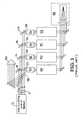
- FIG. 1shows the output of a single frequency master oscillator split into four beams, and directed through separate amplifier chains.
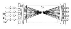
- FIGS. 2A-Cshow the beams entering the conjugator horizontally, propagating over the top of the input mirror, through one of a pair of confocal lenses and focusing inside the cell.
- FIG. 2Dshows a combined beam block/high reflector of the present invention.
- FIG. 3Ashows the beam path for a single input beam.
- FIG. 3Bshows the beam paths for four input beams.
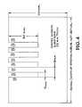
- FIG. 4shows an embodiment of the comb mirror with cutout sections that allow passage of the input beam and reflective areas that reflect one or more beams back for a third pass through the phase conjugator.
- This inventioncombines multiple beams (four in the case of the incorporated patent, but not limited to four) into a single phase locked output beam.
- the output 11 of a single frequency master oscillator 12is split by beamsplitters 14 , 16 , 18 , and 20 into four beams 22 , 24 , 26 and 28 , and directed through separate Faraday isolators 30 , 32 , 34 and 36 amplifier chains 38 , 40 , 42 and 44 .
- the present inventionprovides new ways for combining the four beams within the SBS phase conjugator 46 .
- the beamsare then recombined into a single phase conjugator 46 and routed in a Brillouin-enhanced four wave mixing optical loop, as shown in FIGS. 2A-C.
- the reference beam 100is made to pass through the cell 3 times, with its third pass focus overlapping the focus point of the first pass beam. All beams, including the reference, overlap in a first and second focus. Until the SBS process reaches threshold, the beams transmit through the cell, with the reference beam exiting after three focus passes as shown in FIG. 2 b , and the other beams 102 exiting to a beam block 110 after 2 focus passes (FIG. 2 C).
- each beamretraces its path and is reflected by polarizing beamsplitter 48 out of the system as a spatially coherent phase-locked output beam 50 .
- the beamsenter the conjugator horizontally, propagate over the top of the second pass HR mirror/beam block mirror, propagate through one of a pair of confocal lenses 104 and focus inside the cell.
- the beamscome through focus, pass through a second lens 106 which recollimates them and then hit the rear mirror 108 and are reflected back through the lens and focused in the cell again.
- thisis accomplished by the use of an integral beam block/high reflector (HR) mirror 110 (as shown in FIG. 2D) which includes a beam block portion 112 and an HR portion 114 .
- the beamsexit the cell and the lens and then all but one beam is blocked from reentry into the cell.
- HRhigh reflector
- One beamis selected to be reflected back through the lens and into the cell. This beam is made to focus at the initial multiple beam overlap point, forms a four-wave mixing interaction and generates a reflected array of beams that are all phase locked to each other after they retrace their paths through the amplifier chains and are rejoined in the output.
- This techniqueworks to phase lock the beams but can be limited in specific setups such as in amplifiers that are comprised of rectangular slabs of modest or large (10:1) height to width aspect ratio and in which the beams are zig-zagged through the amplifiers in the width dimension.
- the distortions of the slabs in the non-zig-zag (vertical) dimensioncan impart distortions on the wavefront that spread the beams in the vertical dimension and can cause portions of the beams (and consequently the phase information) to be clipped by the first or second high reflecting mirror. Beam spread due to wavefront errors is minimized at the input to the SBS mirror by optically relaying an image of the amplifier aperture to the first SBS loop mirror.
- propagation in the three passes through the SBS mediumtakes the beam out of the relay image plane and can cause beam distortions that increase the size of the beam. This causes a loss of beam aperture, energy, and phase information which, at the highest average powers of the laser amplifier system, undesirably degrades performance.
- the problemcan be solved with a unique “comb” mirror and a beam setup that enables multiple beams to be combined in a 4-wave mixing architecture that results in good beam mixing and hence highly robust and reliable phase conjugation.
- the comb mirror architecture and a beam pathis shown in FIG. 3 A.
- An input beam 200passes between teeth 1 and 2 of comb mirror 202 , to be focussed at a first focus point by lens 204 of a confocal 1:1 telescope. This foci is located near the center of SBS cell 206 .
- the beamis then recollimated by lens 208 , is reflected from tooth 9 of comb mirror 210 .
- This reflected beamagain passes through lens 208 which brings the beam to a second focus point in the SBS cell 46 after which the beam is recollimated by lens 204 to reflect from tooth 1 of comb mirror 202 .
- This reflected beamagain passes through lens 204 which brings the beam to a focus which overlaps the first focus point, after which the beam expands, is recollimated by lens 208 and exits the system between teeth 9 and 10 of comb mirror 210 .
- beams which enter the system between any of the pairs of teeth of comb mirror 202will be focussed onto the first focus point, reflected by one of the teeth of comb mirror 208 and focussed onto the second focus point to then be reflected by one of the teeth of comb mirror 202 to overlap the first focal point.
- the corresponding reflected beams from comb mirror 110will overlap at the second focus point.
- FIG. 3Bshows the SBS phase conjugator system of FIG. 3A with three additional input beams 212 , 214 and 216 .
- the figureillustrates the overlapping foci of the first and third passes of each beam and further illustrates the overlapping foci of each beam's second pass.
- Input beam 200enters between teeth 1 and 2 and exits between teeth 9 and 10 .
- Input beam 212enters between teeth 2 and 3 and exits between teeth 8 and 9 .
- Input beam 214enters between teeth 3 and 4 and exits between teeth 7 and 8 .
- Input beam 216enters between teeth 4 and 5 and exits between teeth 6 and 7 .
- the SBS phase conjugator systemhas been described using comb mirrors having 5 teeth for a system having 4 input beams; however, comb mirrors having any greater number of teeth for use in a SBS phase conjugator system are contemplated and taught by the present invention.
- the comb mirroritself, shown in one embodiment in FIG. 4, has cutout sections 120 that allow the input beam to pass and reflective areas 122 that reflect one or more beams back for a third pass through the phase conjugator.
- the cut outscan be actual physical cut outs in the mirror substrate or transparent windows in the reflective coating of a solid mirror substrate. Because of the zig-zag nature of the amplifier, thermal loading spreads the beams in the vertical dimension but negligibly in the horizontal. The vertical spreading of the beams is accommodated by the large vertical cut outs and because of the near total lack of spread of the beams in the horizontal dimension, the beams pass completely through the comb cut outs at all power loadings.
- One embodiment of the comb mirroris about 150 mm by 100 mm and the comb cut outs are 9 mm by 50 mm.
- the comb mirror architectureis found to greatly improved multi-beam locking performance under all conditions. This is attributed to the fact that the multiple beams are focused into the SBS gain medium and the four wave mixing loop is all formed by horizontal beam deflections, keeping all of the input beams and subsequent folded passes approximately in a single plane. This improves overlap and mixing between the beams where weak four wave mixing interactions, even at lower intensities away from focus, contribute to the improvement in overall stability.
- high pressure gassesthat have an acoustic response time in the range of 15 ns are the preferred SBS gain media.
- Gasescan include nitrogen or xenon at 40 to 100 atmospheres pressure.
- the preferred SBS gain mediamay be a liquid, e.g., Carbon tetrachloride and certain freon or fluorinerts. In all, this four wave mixing/comb mirror phase locking technique can produce solidly phase locked beams for short and long pulse laser amplifier systems.
Landscapes
- Physics & Mathematics (AREA)
- Electromagnetism (AREA)
- Engineering & Computer Science (AREA)
- Plasma & Fusion (AREA)
- Optics & Photonics (AREA)
- Optical Modulation, Optical Deflection, Nonlinear Optics, Optical Demodulation, Optical Logic Elements (AREA)
Abstract
Description
Claims (20)
Priority Applications (1)
| Application Number | Priority Date | Filing Date | Title |
|---|---|---|---|
| US09/495,019US6385228B1 (en) | 1999-01-29 | 2000-01-31 | Coherent beam combiner for a high power laser |
Applications Claiming Priority (2)
| Application Number | Priority Date | Filing Date | Title |
|---|---|---|---|
| US11776899P | 1999-01-29 | 1999-01-29 | |
| US09/495,019US6385228B1 (en) | 1999-01-29 | 2000-01-31 | Coherent beam combiner for a high power laser |
Publications (1)
| Publication Number | Publication Date |
|---|---|
| US6385228B1true US6385228B1 (en) | 2002-05-07 |
Family
ID=26815630
Family Applications (1)
| Application Number | Title | Priority Date | Filing Date |
|---|---|---|---|
| US09/495,019Expired - Fee RelatedUS6385228B1 (en) | 1999-01-29 | 2000-01-31 | Coherent beam combiner for a high power laser |
Country Status (1)
| Country | Link |
|---|---|
| US (1) | US6385228B1 (en) |
Cited By (34)
| Publication number | Priority date | Publication date | Assignee | Title |
|---|---|---|---|---|
| US6693943B1 (en) | 2002-10-04 | 2004-02-17 | The Regents Of The University Of California | Phased laser array for generating a powerful laser beam |
| US20040146083A1 (en)* | 2002-09-12 | 2004-07-29 | Bodo Ehlers | Apparatus for shaping the output beam of semiconductor lasers |
| US20050000953A1 (en)* | 2003-07-03 | 2005-01-06 | Perozek Paul Michael | Reducing electromagnetic feedback during laser shock peening |
| US20050040149A1 (en)* | 2003-08-22 | 2005-02-24 | Rockstroh Todd Jay | Single head laser high throughput laser shock peening |
| US20050207465A1 (en)* | 2004-03-18 | 2005-09-22 | The Regents Of The University Of California | Phasing surface emitting diode laser outputs into a coherent laser beam |
| US20050281101A1 (en)* | 2004-06-18 | 2005-12-22 | Bruland Kelly J | Semiconductor structure processing using multiple laterally spaced laser beam spots with on-axis offset |
| US20050281102A1 (en)* | 2004-06-18 | 2005-12-22 | Bruland Kelly J | Semiconductor structure processing using multiple laterally spaced laser beam spots with joint velocity profiling |
| US20050279736A1 (en)* | 2004-06-18 | 2005-12-22 | Bruland Kelly J | Semiconductor structure processing using multiple laser beam spots spaced on-axis with cross-axis offset |
| US20050282407A1 (en)* | 2004-06-18 | 2005-12-22 | Bruland Kelly J | Semiconductor structure processing using multiple laser beam spots spaced on-axis delivered simultaneously |
| US20050282367A1 (en)* | 2004-06-18 | 2005-12-22 | Bruland Kelly J | Semiconductor structure processing using multiple laser beam spots spaced on-axis on non-adjacent structures |
| US20050282319A1 (en)* | 2004-06-18 | 2005-12-22 | Bruland Kelly J | Semiconductor structure processing using multiple laser beam spots overlapping lengthwise on a structure |
| US20050282406A1 (en)* | 2004-06-18 | 2005-12-22 | Bruland Kelly J | Semiconductor structure processing using multiple laterally spaced laser beam spots delivering multiple blows |
| US20060006158A1 (en)* | 2004-07-09 | 2006-01-12 | Lawrence Wayne L | Continuous motion laser shock peening |
| US20060078015A1 (en)* | 2004-10-07 | 2006-04-13 | United States Of America As Represented By The Dept Of The Army | Zonal lenslet array |
| US20060171428A1 (en)* | 2005-02-03 | 2006-08-03 | Pd-Ld, Inc. | High-power, phased-locked, laser arrays |
| US20060215972A1 (en)* | 2002-03-15 | 2006-09-28 | Pd-Ld, Inc. | Fiber optic devices having volume Bragg grating elements |
| US20060251143A1 (en)* | 2003-07-03 | 2006-11-09 | Volodin Boris L | Apparatus and methods for altering a characteristic of light-emitting device |
| US20070053393A1 (en)* | 2003-09-03 | 2007-03-08 | Korea Advanced Institute Of Science And Technology | Apparatus and method for self-phase control with stimulated brillouin scattering phase conjugate mirror |
| US7239777B1 (en) | 2006-03-09 | 2007-07-03 | Lockheed Martin Coherent Technologies, Inc. | Method and apparatus to coherently combine high-power beams in self-imaging waveguides |
| US20070211995A1 (en)* | 2006-03-09 | 2007-09-13 | Christensen Scott E | Laser beam transformation and combination using tapered waveguides |
| WO2007129794A1 (en)* | 2006-05-09 | 2007-11-15 | Korea Advanced Institute Of Science And Technology | Confocal laser glass-cutting apparatus using stimulated brillouin scattering- phase conjugate mirror |
| US20080121627A1 (en)* | 2004-06-18 | 2008-05-29 | Electro Scientific Industries, Inc. | Methods and systems for semiconductor structure processing using multiple laser beam spots |
| US20090086297A1 (en)* | 2002-03-15 | 2009-04-02 | Pd-Ld, Inc. | Bragg grating elements for optical devices |
| US20090142073A1 (en)* | 2007-11-30 | 2009-06-04 | Smith Irl W | Method and apparatus for maintaining a coherent combined beam during arbitrary steering |
| US20090153950A1 (en)* | 2006-03-08 | 2009-06-18 | Korea Advanced Institute Of Science And Technology | Phase Stabilization Device For Stimulated Brillouin Scattering Phase Conjugate Mirrors And Light Amplification Apparatus Using The Same |
| US20100164603A1 (en)* | 2008-12-30 | 2010-07-01 | Hafez Walid M | Programmable fuse and anti-fuse elements and methods of changing conduction states of same |
| US7792003B2 (en) | 2003-09-26 | 2010-09-07 | Pd-Ld, Inc. | Methods for manufacturing volume Bragg grating elements |
| CN101907781A (en)* | 2010-07-13 | 2010-12-08 | 杭州电子科技大学 | A method for manufacturing an optical flat plate with beam converging function |
| US8169693B1 (en) | 2009-08-13 | 2012-05-01 | The United States Of America As Represented By The Secretary Of The Air Force | Fiber bundle phase conjugate mirror |
| CN104269733A (en)* | 2014-10-25 | 2015-01-07 | 哈尔滨工业大学 | Two-dimensional waveguide type medium pond used for amplifying serial laser beam combinations with Brillouin amplifier |
| CN104682188A (en)* | 2015-03-31 | 2015-06-03 | 吕志伟 | Modular non-collinear serial beam-forming laser based on stimulated Brillouin scattering |
| CN104882771A (en)* | 2015-06-16 | 2015-09-02 | 吕志伟 | High energy and high power SBS beam combining method and beam combining laser |
| CN110021873A (en)* | 2019-05-28 | 2019-07-16 | 长春理工大学 | A kind of laser based on cascade stimulated scattering |
| US11698304B2 (en)* | 2019-02-15 | 2023-07-11 | Wayne State University | Apparatuses, systems, and methods for detecting materials based on Raman spectroscopy |
Citations (1)
| Publication number | Priority date | Publication date | Assignee | Title |
|---|---|---|---|---|
| US5880873A (en)* | 1997-05-16 | 1999-03-09 | The Regents Of The University Of California | All solid-state SBS phase conjugate mirror |
- 2000
- 2000-01-31USUS09/495,019patent/US6385228B1/ennot_activeExpired - Fee Related
Patent Citations (1)
| Publication number | Priority date | Publication date | Assignee | Title |
|---|---|---|---|---|
| US5880873A (en)* | 1997-05-16 | 1999-03-09 | The Regents Of The University Of California | All solid-state SBS phase conjugate mirror |
Cited By (79)
| Publication number | Priority date | Publication date | Assignee | Title |
|---|---|---|---|---|
| US7949216B2 (en) | 2002-03-15 | 2011-05-24 | Pd-Ld, Inc. | Bragg grating elements for optical devices |
| US20060215972A1 (en)* | 2002-03-15 | 2006-09-28 | Pd-Ld, Inc. | Fiber optic devices having volume Bragg grating elements |
| US20090086297A1 (en)* | 2002-03-15 | 2009-04-02 | Pd-Ld, Inc. | Bragg grating elements for optical devices |
| US7528385B2 (en) | 2002-03-15 | 2009-05-05 | Pd-Ld, Inc. | Fiber optic devices having volume Bragg grating elements |
| US7817888B2 (en) | 2002-03-15 | 2010-10-19 | Pd-Ld, Inc. | Bragg grating elements for optical devices |
| US20040146083A1 (en)* | 2002-09-12 | 2004-07-29 | Bodo Ehlers | Apparatus for shaping the output beam of semiconductor lasers |
| US7065105B2 (en)* | 2002-09-12 | 2006-06-20 | Fraunhofer Usa, Inc. | Apparatus for shaping the output beam of semiconductor lasers |
| US6693943B1 (en) | 2002-10-04 | 2004-02-17 | The Regents Of The University Of California | Phased laser array for generating a powerful laser beam |
| US7633985B2 (en) | 2003-07-03 | 2009-12-15 | Pd-Ld, Inc. | Apparatus and methods for altering a characteristic of light-emitting device |
| US6917012B2 (en) | 2003-07-03 | 2005-07-12 | General Electric Company | Reducing electromagnetic feedback during laser shock peening |
| US9793674B2 (en) | 2003-07-03 | 2017-10-17 | Necsel Intellectual Property, Inc. | Chirped Bragg grating elements |
| US7796673B2 (en) | 2003-07-03 | 2010-09-14 | Pd-Ld, Inc. | Apparatus and methods for altering a characteristic of a light-emitting device |
| US20080253424A1 (en)* | 2003-07-03 | 2008-10-16 | Boris Leonidovich Volodin | Use of Volume Bragg Gratings For The Conditioning Of Laser Emission Characteristics |
| US7697589B2 (en) | 2003-07-03 | 2010-04-13 | Pd-Ld, Inc. | Use of volume Bragg gratings for the conditioning of laser emission characteristics |
| US20080267246A1 (en)* | 2003-07-03 | 2008-10-30 | Pd-Ld, Inc. | Apparatus And Methods For Altering A Characteristic Of A Light-Emitting Device |
| US7590162B2 (en) | 2003-07-03 | 2009-09-15 | Pd-Ld, Inc. | Chirped bragg grating elements |
| US10205295B2 (en) | 2003-07-03 | 2019-02-12 | Necsel Intellectual Property, Inc. | Chirped Bragg grating elements |
| US8306088B2 (en) | 2003-07-03 | 2012-11-06 | Pd-Ld, Inc. | Bragg grating elements for the conditioning of laser emission characteristics |
| US20070047608A1 (en)* | 2003-07-03 | 2007-03-01 | Pd-Ld, Inc. | Use of volume bragg gratings for the conditioning of laser emission characteristics |
| US20060256830A1 (en)* | 2003-07-03 | 2006-11-16 | Pd-Ld, Inc. | Bragg grating elements for the conditioning of laser emission characteristics |
| US20050000953A1 (en)* | 2003-07-03 | 2005-01-06 | Perozek Paul Michael | Reducing electromagnetic feedback during laser shock peening |
| US20060251143A1 (en)* | 2003-07-03 | 2006-11-09 | Volodin Boris L | Apparatus and methods for altering a characteristic of light-emitting device |
| US20060251134A1 (en)* | 2003-07-03 | 2006-11-09 | Volodin Boris L | Apparatus and methods for altering a characteristic of a light-emitting device |
| US20050040149A1 (en)* | 2003-08-22 | 2005-02-24 | Rockstroh Todd Jay | Single head laser high throughput laser shock peening |
| US6900409B2 (en) | 2003-08-22 | 2005-05-31 | General Electric Company | Single head laser high throughput laser shock peening |
| US20070053393A1 (en)* | 2003-09-03 | 2007-03-08 | Korea Advanced Institute Of Science And Technology | Apparatus and method for self-phase control with stimulated brillouin scattering phase conjugate mirror |
| US7436581B2 (en)* | 2003-09-03 | 2008-10-14 | Korea Advanced Institute Of Science And Technology (Kaist) | Apparatus and method for self-phase control with stimulated Brillouin scattering phase conjugate mirror |
| US7792003B2 (en) | 2003-09-26 | 2010-09-07 | Pd-Ld, Inc. | Methods for manufacturing volume Bragg grating elements |
| US7120184B2 (en) | 2004-03-18 | 2006-10-10 | The Regents Of The University Of California | Phasing surface emitting diode laser outputs into a coherent laser beam |
| US20050207465A1 (en)* | 2004-03-18 | 2005-09-22 | The Regents Of The University Of California | Phasing surface emitting diode laser outputs into a coherent laser beam |
| US20050279736A1 (en)* | 2004-06-18 | 2005-12-22 | Bruland Kelly J | Semiconductor structure processing using multiple laser beam spots spaced on-axis with cross-axis offset |
| US7935941B2 (en) | 2004-06-18 | 2011-05-03 | Electro Scientific Industries, Inc. | Semiconductor structure processing using multiple laser beam spots spaced on-axis on non-adjacent structures |
| US7425471B2 (en) | 2004-06-18 | 2008-09-16 | Electro Scientific Industries, Inc. | Semiconductor structure processing using multiple laser beam spots spaced on-axis with cross-axis offset |
| US20050282319A1 (en)* | 2004-06-18 | 2005-12-22 | Bruland Kelly J | Semiconductor structure processing using multiple laser beam spots overlapping lengthwise on a structure |
| US20050281101A1 (en)* | 2004-06-18 | 2005-12-22 | Bruland Kelly J | Semiconductor structure processing using multiple laterally spaced laser beam spots with on-axis offset |
| US8383982B2 (en) | 2004-06-18 | 2013-02-26 | Electro Scientific Industries, Inc. | Methods and systems for semiconductor structure processing using multiple laser beam spots |
| US20050281102A1 (en)* | 2004-06-18 | 2005-12-22 | Bruland Kelly J | Semiconductor structure processing using multiple laterally spaced laser beam spots with joint velocity profiling |
| US8148211B2 (en) | 2004-06-18 | 2012-04-03 | Electro Scientific Industries, Inc. | Semiconductor structure processing using multiple laser beam spots spaced on-axis delivered simultaneously |
| US20080121627A1 (en)* | 2004-06-18 | 2008-05-29 | Electro Scientific Industries, Inc. | Methods and systems for semiconductor structure processing using multiple laser beam spots |
| US20110186555A1 (en)* | 2004-06-18 | 2011-08-04 | Bruland Kelly J | System for semiconductor structure processing using multiple laser beam spots |
| US7435927B2 (en) | 2004-06-18 | 2008-10-14 | Electron Scientific Industries, Inc. | Semiconductor link processing using multiple laterally spaced laser beam spots with on-axis offset |
| US7923306B2 (en) | 2004-06-18 | 2011-04-12 | Electro Scientific Industries, Inc. | Semiconductor structure processing using multiple laser beam spots |
| US20050279739A1 (en)* | 2004-06-18 | 2005-12-22 | Bruland Kelly J | Semiconductor structure processing using multiple laser beam spots spaced on-axis to increase single-blow throughput |
| US20050282407A1 (en)* | 2004-06-18 | 2005-12-22 | Bruland Kelly J | Semiconductor structure processing using multiple laser beam spots spaced on-axis delivered simultaneously |
| US7629234B2 (en) | 2004-06-18 | 2009-12-08 | Electro Scientific Industries, Inc. | Semiconductor structure processing using multiple laterally spaced laser beam spots with joint velocity profiling |
| US7633034B2 (en) | 2004-06-18 | 2009-12-15 | Electro Scientific Industries, Inc. | Semiconductor structure processing using multiple laser beam spots overlapping lengthwise on a structure |
| US20050282406A1 (en)* | 2004-06-18 | 2005-12-22 | Bruland Kelly J | Semiconductor structure processing using multiple laterally spaced laser beam spots delivering multiple blows |
| US20050282367A1 (en)* | 2004-06-18 | 2005-12-22 | Bruland Kelly J | Semiconductor structure processing using multiple laser beam spots spaced on-axis on non-adjacent structures |
| US7687740B2 (en) | 2004-06-18 | 2010-03-30 | Electro Scientific Industries, Inc. | Semiconductor structure processing using multiple laterally spaced laser beam spots delivering multiple blows |
| US8319150B2 (en) | 2004-07-09 | 2012-11-27 | General Electric Company | Continuous motion laser shock peening |
| US20060006158A1 (en)* | 2004-07-09 | 2006-01-12 | Lawrence Wayne L | Continuous motion laser shock peening |
| US20060078015A1 (en)* | 2004-10-07 | 2006-04-13 | United States Of America As Represented By The Dept Of The Army | Zonal lenslet array |
| US20100027103A1 (en)* | 2004-10-07 | 2010-02-04 | United States Of America, As Represented By The Secretary Of Army | Zonal Lenslet Array |
| US7619811B2 (en)* | 2004-10-07 | 2009-11-17 | The United States of America as represented by the Secretary of the Army Pentagon | Zonal lenslet array |
| US7957056B2 (en)* | 2004-10-07 | 2011-06-07 | The United States Of America As Represented By The Secretary Of The Army | Zonal lenslet array |
| WO2006083998A3 (en)* | 2005-02-03 | 2007-09-20 | Pd Ld Inc | High-power, phased-locked, laser arrays |
| US20060171428A1 (en)* | 2005-02-03 | 2006-08-03 | Pd-Ld, Inc. | High-power, phased-locked, laser arrays |
| US7949030B2 (en)* | 2005-02-03 | 2011-05-24 | Pd-Ld, Inc. | High-power, phased-locked, laser arrays |
| US20090153950A1 (en)* | 2006-03-08 | 2009-06-18 | Korea Advanced Institute Of Science And Technology | Phase Stabilization Device For Stimulated Brillouin Scattering Phase Conjugate Mirrors And Light Amplification Apparatus Using The Same |
| US8035890B2 (en)* | 2006-03-08 | 2011-10-11 | Korea Advanced Institute Of Science And Technology | Phase stabilization device for stimulated brillouin scattering phase conjugate mirrors and light amplification apparatus using the same |
| US7313299B2 (en) | 2006-03-09 | 2007-12-25 | Lockheed Martin Coherent Technologies, Inc. | Laser beam transformation and combination using tapered waveguides |
| US7239777B1 (en) | 2006-03-09 | 2007-07-03 | Lockheed Martin Coherent Technologies, Inc. | Method and apparatus to coherently combine high-power beams in self-imaging waveguides |
| US20070211995A1 (en)* | 2006-03-09 | 2007-09-13 | Christensen Scott E | Laser beam transformation and combination using tapered waveguides |
| WO2007129794A1 (en)* | 2006-05-09 | 2007-11-15 | Korea Advanced Institute Of Science And Technology | Confocal laser glass-cutting apparatus using stimulated brillouin scattering- phase conjugate mirror |
| US20090142073A1 (en)* | 2007-11-30 | 2009-06-04 | Smith Irl W | Method and apparatus for maintaining a coherent combined beam during arbitrary steering |
| WO2009073158A1 (en)* | 2007-11-30 | 2009-06-11 | Raytheon Company | Method and apparatus for maintaining a coherent combined beam during arbitrary steering |
| US8594511B2 (en) | 2007-11-30 | 2013-11-26 | Raytheon Company | Method and apparatus for maintaining a coherent combined beam during arbitrary steering |
| US20100164603A1 (en)* | 2008-12-30 | 2010-07-01 | Hafez Walid M | Programmable fuse and anti-fuse elements and methods of changing conduction states of same |
| US8169693B1 (en) | 2009-08-13 | 2012-05-01 | The United States Of America As Represented By The Secretary Of The Air Force | Fiber bundle phase conjugate mirror |
| CN101907781B (en)* | 2010-07-13 | 2012-04-18 | 杭州电子科技大学 | A method for manufacturing an optical flat plate with beam converging function |
| CN101907781A (en)* | 2010-07-13 | 2010-12-08 | 杭州电子科技大学 | A method for manufacturing an optical flat plate with beam converging function |
| CN104269733A (en)* | 2014-10-25 | 2015-01-07 | 哈尔滨工业大学 | Two-dimensional waveguide type medium pond used for amplifying serial laser beam combinations with Brillouin amplifier |
| CN104269733B (en)* | 2014-10-25 | 2017-02-22 | 哈尔滨工业大学 | Two-dimensional waveguide type medium pond used for amplifying serial laser beam combinations with Brillouin amplifier |
| CN104682188A (en)* | 2015-03-31 | 2015-06-03 | 吕志伟 | Modular non-collinear serial beam-forming laser based on stimulated Brillouin scattering |
| CN104682188B (en)* | 2015-03-31 | 2017-10-31 | 吕志伟 | Modular non-collinear serial beam combination laser based on stimulated Brillouin scattering |
| CN104882771A (en)* | 2015-06-16 | 2015-09-02 | 吕志伟 | High energy and high power SBS beam combining method and beam combining laser |
| US11698304B2 (en)* | 2019-02-15 | 2023-07-11 | Wayne State University | Apparatuses, systems, and methods for detecting materials based on Raman spectroscopy |
| CN110021873A (en)* | 2019-05-28 | 2019-07-16 | 长春理工大学 | A kind of laser based on cascade stimulated scattering |
| CN110021873B (en)* | 2019-05-28 | 2023-10-13 | 长春理工大学 | Laser based on cascade stimulated scattering |
Similar Documents
| Publication | Publication Date | Title |
|---|---|---|
| US6385228B1 (en) | Coherent beam combiner for a high power laser | |
| US6198069B1 (en) | Laser beam temporal and spatial tailoring for laser shock processing | |
| EP0259439B1 (en) | Efficient phase conjugate laser | |
| EP1192690B1 (en) | Multi-pass optical amplifier | |
| KR101405548B1 (en) | Spatial filters for high average power lasers | |
| EP0745282B1 (en) | System for minimizing the depolarization of a laser beam due to thermally induced birefringence | |
| US5790574A (en) | Low cost, high average power, high brightness solid state laser | |
| US5434875A (en) | Low cost, high average power, high brightness solid state laser | |
| US6081543A (en) | Stretcher-compressor assembly having a single grating | |
| US5644424A (en) | Laser amplifier and method | |
| US8670175B2 (en) | Method and system for compact and efficient high energy pulsed laser amplifier | |
| WO1996042129A1 (en) | Long-pulse-width narrow-bandwidth laser | |
| US4156852A (en) | Multipass laser amplification with near-field far-field optical separation | |
| US5832020A (en) | Solid-state laser forming highly-repetitive, high-energy and high-power laser beam | |
| US5880873A (en) | All solid-state SBS phase conjugate mirror | |
| EP0792530A1 (en) | Low cost, high average power, high brightness solid state laser | |
| US7133427B2 (en) | Phase conjugate laser and method with improved fidelity | |
| US20100034222A1 (en) | Laser source for lidar application | |
| US5535049A (en) | Phase and birefringence aberration correction | |
| US20230275385A1 (en) | Short pulse laser system | |
| EP1794853B1 (en) | Spatial filter for phase conjugate laser | |
| Rockwell et al. | Energy scaling of phase-conjugate lasers and Brillouin conjugators | |
| Zeitner et al. | High modal discrimination for laser resonators with Gaussian output beam | |
| US6693943B1 (en) | Phased laser array for generating a powerful laser beam | |
| Basov et al. | Explosively pumped photodissociation lasers with phase conjugation |
Legal Events
| Date | Code | Title | Description |
|---|---|---|---|
| AS | Assignment | Owner name:CALIFORNIA, REGENTS OF THE UNIVERSITY OF, THE, CAL Free format text:ASSIGNMENT OF ASSIGNORS INTEREST;ASSIGNORS:HACKEL, LLOYD A.;DANE, C. BRENT;REEL/FRAME:010745/0584 Effective date:20000301 Owner name:REGENTS OF THE UNIVERSITY OF CALIFORNIA, THE, CALI Free format text:ASSIGNMENT OF ASSIGNORS INTEREST;ASSIGNORS:HACKEL, LLOYD A.;DANE, C. BRENT;REEL/FRAME:010745/0584 Effective date:20000301 | |
| AS | Assignment | Owner name:ENERGY, U.S. DEPARTMENT OF, CALIFORNIA Free format text:CONFIRMATORY LICENSE;ASSIGNOR:CALIFORNIA, UNIVERSITY OF;REEL/FRAME:010946/0651 Effective date:20000607 | |
| FPAY | Fee payment | Year of fee payment:4 | |
| AS | Assignment | Owner name:LAWRENCE LIVERMORE NATIONAL SECURITY LLC, CALIFORN Free format text:ASSIGNMENT OF ASSIGNORS INTEREST;ASSIGNOR:THE REGENTS OF THE UNIVERSITY OF CALIFORNIA;REEL/FRAME:021217/0050 Effective date:20080623 | |
| FEPP | Fee payment procedure | Free format text:PAYOR NUMBER ASSIGNED (ORIGINAL EVENT CODE: ASPN); ENTITY STATUS OF PATENT OWNER: LARGE ENTITY Free format text:PAT HOLDER NO LONGER CLAIMS SMALL ENTITY STATUS, ENTITY STATUS SET TO UNDISCOUNTED (ORIGINAL EVENT CODE: STOL); ENTITY STATUS OF PATENT OWNER: LARGE ENTITY | |
| REMI | Maintenance fee reminder mailed | ||
| FPAY | Fee payment | Year of fee payment:8 | |
| SULP | Surcharge for late payment | Year of fee payment:7 | |
| REMI | Maintenance fee reminder mailed | ||
| LAPS | Lapse for failure to pay maintenance fees | ||
| STCH | Information on status: patent discontinuation | Free format text:PATENT EXPIRED DUE TO NONPAYMENT OF MAINTENANCE FEES UNDER 37 CFR 1.362 | |
| FP | Lapsed due to failure to pay maintenance fee | Effective date:20140507 |