US6385197B1 - Virtual port trunking method and apparatus - Google Patents
Virtual port trunking method and apparatusDownload PDFInfo
- Publication number
- US6385197B1 US6385197B1US09/350,748US35074899AUS6385197B1US 6385197 B1US6385197 B1US 6385197B1US 35074899 AUS35074899 AUS 35074899AUS 6385197 B1US6385197 B1US 6385197B1
- Authority
- US
- United States
- Prior art keywords
- port
- ports
- virtual port
- network
- physical ports
- Prior art date
- Legal status (The legal status is an assumption and is not a legal conclusion. Google has not performed a legal analysis and makes no representation as to the accuracy of the status listed.)
- Expired - Lifetime
Links
- 238000000034methodMethods0.000titleclaimsabstractdescription18
- 238000004891communicationMethods0.000claimsabstractdescription13
- 238000013507mappingMethods0.000claimsdescription16
- 238000001914filtrationMethods0.000claimsdescription3
- 230000000873masking effectEffects0.000claims2
- 230000004044responseEffects0.000claims1
- 230000009467reductionEffects0.000abstractdescription3
- 238000012545processingMethods0.000abstractdescription2
- 238000007726management methodMethods0.000description60
- 239000003795chemical substances by applicationSubstances0.000description14
- 230000006870functionEffects0.000description7
- 108700010388MIBsProteins0.000description4
- 230000007246mechanismEffects0.000description4
- 230000008569processEffects0.000description4
- 238000007792additionMethods0.000description3
- 230000002776aggregationEffects0.000description3
- 238000004220aggregationMethods0.000description3
- 238000012217deletionMethods0.000description3
- 230000037430deletionEffects0.000description3
- 239000000523sampleSubstances0.000description3
- 230000009471actionEffects0.000description2
- 230000008901benefitEffects0.000description2
- 238000006243chemical reactionMethods0.000description2
- 238000010586diagramMethods0.000description2
- 238000012423maintenanceMethods0.000description2
- 239000011159matrix materialSubstances0.000description2
- 238000012544monitoring processMethods0.000description2
- 238000004458analytical methodMethods0.000description1
- 238000004364calculation methodMethods0.000description1
- 239000007795chemical reaction productSubstances0.000description1
- 238000013523data managementMethods0.000description1
- 238000013461designMethods0.000description1
- 238000003745diagnosisMethods0.000description1
- 238000005516engineering processMethods0.000description1
- 230000008447perceptionEffects0.000description1
- 230000000704physical effectEffects0.000description1
- 238000013439planningMethods0.000description1
- 230000011218segmentationEffects0.000description1
- 230000007480spreadingEffects0.000description1
- 230000007704transitionEffects0.000description1
Images


Classifications
- H—ELECTRICITY
- H04—ELECTRIC COMMUNICATION TECHNIQUE
- H04L—TRANSMISSION OF DIGITAL INFORMATION, e.g. TELEGRAPHIC COMMUNICATION
- H04L41/00—Arrangements for maintenance, administration or management of data switching networks, e.g. of packet switching networks
- H04L41/02—Standardisation; Integration
- H04L41/0213—Standardised network management protocols, e.g. simple network management protocol [SNMP]
- H—ELECTRICITY
- H04—ELECTRIC COMMUNICATION TECHNIQUE
- H04L—TRANSMISSION OF DIGITAL INFORMATION, e.g. TELEGRAPHIC COMMUNICATION
- H04L45/00—Routing or path finding of packets in data switching networks
- H04L45/24—Multipath
- H04L45/245—Link aggregation, e.g. trunking
- H—ELECTRICITY
- H04—ELECTRIC COMMUNICATION TECHNIQUE
- H04L—TRANSMISSION OF DIGITAL INFORMATION, e.g. TELEGRAPHIC COMMUNICATION
- H04L49/00—Packet switching elements
- H04L49/35—Switches specially adapted for specific applications
- H04L49/351—Switches specially adapted for specific applications for local area network [LAN], e.g. Ethernet switches
- H—ELECTRICITY
- H04—ELECTRIC COMMUNICATION TECHNIQUE
- H04L—TRANSMISSION OF DIGITAL INFORMATION, e.g. TELEGRAPHIC COMMUNICATION
- H04L49/00—Packet switching elements
- H04L49/10—Packet switching elements characterised by the switching fabric construction
- H04L49/101—Packet switching elements characterised by the switching fabric construction using crossbar or matrix
- Y—GENERAL TAGGING OF NEW TECHNOLOGICAL DEVELOPMENTS; GENERAL TAGGING OF CROSS-SECTIONAL TECHNOLOGIES SPANNING OVER SEVERAL SECTIONS OF THE IPC; TECHNICAL SUBJECTS COVERED BY FORMER USPC CROSS-REFERENCE ART COLLECTIONS [XRACs] AND DIGESTS
- Y02—TECHNOLOGIES OR APPLICATIONS FOR MITIGATION OR ADAPTATION AGAINST CLIMATE CHANGE
- Y02D—CLIMATE CHANGE MITIGATION TECHNOLOGIES IN INFORMATION AND COMMUNICATION TECHNOLOGIES [ICT], I.E. INFORMATION AND COMMUNICATION TECHNOLOGIES AIMING AT THE REDUCTION OF THEIR OWN ENERGY USE
- Y02D30/00—Reducing energy consumption in communication networks
- Y02D30/50—Reducing energy consumption in communication networks in wire-line communication networks, e.g. low power modes or reduced link rate
Definitions
- the present inventionrelates generally to the management of network switches and more particularly to a mechanism for simplifying the maintenance of the ports of a network switch.
- FIG. 1shows a typical network management model 100 .
- the underlying baseconsists of the network management applications 110 used to manage the network. These management applications should have a consistent end-user interface and preferably a command data repository. It goes without saying that the user interface must be intuitive, user friendly, customizable, and consistent across all the applications.
- a common data repository 120is desirable to avoid duplication of data and to allow access to the stored information by all applications.
- network management applications 110should snap together seamlessly with desktop and business management applications.
- MIBManagement Information Base
- the MIBis a collection of information (or objects) about the managed device. Although the term MIB can be used to mean many different things, we use it to mean the actual data stored in an SNMP device or the description of that data. These MIB objects are standardized across a class of devices, so a management station can retrieve all object information from various devices or cause an action to take place at an agent by manipulating these objects. The configuration settings of a device can also be changed by this method.
- SNMP management systemscan manage these devices from a central site and view information graphically.
- the many SNMP management applications available todayusually run on most of the current operating systems, such as UNIX, Windows (TM) 98 , and Windows NT (TM) 5.0.
- Most high-end productsare designed to cope with relatively large networks and thus run on powerful machines using the scaleable UNIX operating system.
- the SNMP operational modelis based on four elements: the management station, the management agent, the network management protocol, and the Management Information Base (MIB).
- the management stationserves as an interface tool to the managed elements of the network.
- the management stationusually has a graphical user interface that is used to monitor and control the network via a network interface card (NIC).
- NICnetwork interface card
- FIG. 2shows a network system 200 comprising a network manager 210 and a network agent 220 .
- the network management protocol used for intercommunication between the management station and the agentsis actually called SNMP and has the following defined functions:
- GetNextallows the management station to retrieve the next sequential information in the management objects from the agent.
- Trapis an unsolicited message from the agent to the management station that notifies the management station of any important events.
- a managed devicehas a management agent that responds to requests for information and requests for actions from the management station. This agent may also provide the management station with unsolicited information by means of a trap. Key network devices, such as hubs, routers, and bridges, must therefore provide this management agent (often referred to as an SNMP agent or as being SNMP-capable) for them to be manageable via the SNMP management station.
- This management agent(often referred to as an SNMP agent or as being SNMP-capable) for them to be manageable via the SNMP management station.
- RMONis especially useful in monitoring and managing LANs.
- RMONwas drafted by the IETF and became a proposed standard in 1992 as RFC number 1271.
- the RMON specificationwas developed to provide traffic statistics and analysis on many network parameters for comprehensive network fault diagnosis, planning, and performance tuning. Ethernet was the initial focus and is described in the RFC 1271, but the remote monitoring functions were also extended to Token Ring in 1993 as RFC 1513.
- RMONprovides a standard set of MIBs that collect rich network statistical information not available through the basic SNMP MIBs. This information is basically everything you ever wanted to know about switches, so it is crucial in the management of network systems.
- RMONallows proactive network diagnostics by utilization of its powerful Alarm group.
- the Alarm groupenables thresholds to be set for critical network parameters to automatically deliver alerts to centrally located management consoles. This is especially critical when managing Gigabit Ethernet switches, because full-wire speed management at that speed is virtually impossible.
- RMONis especially critical for managing switches from a remote location because a switch keeps a full MIB information on a per-port basis, not a per-device basis. If you used regular SNMP to monitor a switch, port by port, it would result in a huge amount of SNMP traffic. With RMON support internal to the switch, this can be a quick and easy task.
- An RMON-enabled switchis responsible for collecting and acting on its own data as well as forwarding information to a central management station.
- Configuration managementconsists of two major elements. One is the tracking of the physical and logical configuration of your network, and the second pertains to the configuration and upgrading of network devices such as hubs, switches, and routers.
- Configuration management of the physical and logical topologyis probably the most important part of network management in that the user cannot accurately manage a network unless the user can manage the configuration of the network. This is often done with help from powerful network configuration tools. Some network configuration tools will allow for both a physical and logical version of the network to be drawn, and keep a history of adds, moves, and changes to the network. This history becomes especially important when making the transition from shared media to a switch environment. It may be advantageous to go back to a previous configuration should there be problems with the new one, so make sure to back up this precious data often. Changes, additions, and deletions from the network need to dynamically update the configuration application's database to ensure consistency between the mapping of the real network and what the application represents.
- DMTFDesktop Management Task Force
- the industry working groupsare defining a standard way to attribute a managed object, such as a router, switch, hub or NIC, to a particular database scheme.
- the database schemewill use this information to map network objects, PCs, and servers into an overall configuration.
- the advantage of this methodis the configuration will automatically be updated when a network device changes its location or configuration.
- Performance managementis important for determining whether the user need to upgrade an existing network to Switched or Fast Ethernet. Performance management, however, needs to be a continuous task. Performance management can also help identify areas where switching or Fast Ethernet technology is not being utilized to its full extent.
- the usercan either configure the management station to poll for this data or set some thresholds in the switch and then perform calculations to compare the performance of that segment to some predetermined values. It is important to have some idea of what the baseline figures should be to make sensible decisions. Some applications can be used to monitor segments for a period of time and then recommend threshold figures. Having said that, traffic patterns vary from segment to segment and are generally based on intimate knowledge of the network and the perception of how it should behave.
- trunking groupscomprising five trunking links connecting five ports of node 1 and five ports of node 4
- port information on all five trunking ports of node 1 and node 4are required to be stored in the network manager.
- port configuration data of a total of 10 ports(5 ports from node 1 and 5 ports from node 2 ) are maintained in the network manager. Because of the trunking definition, the port information on each of these trunking ports on either node are very similar, and redundant.
- the present inventiondiscloses a novel virtual port method and apparatus for use in the communication between multiple nodes in a network system.
- the virtual port conceptis implemented in a switching unit comprising a plurality of physical ports.
- at least one virtual portcan be defined by the user to represent a corresponding number of group of physical ports.
- a single virtual port identificationcan be used by the network manager to identify all the physical ports belonging to a trunking group.
- FIG. 1shows a typical network management model.
- FIG. 2shows a conventional network system having a network manager and a network agent.
- FIG. 3shows a simplified network control system having a network manager and a plurality of network nodes connected to the network manager.
- FIG. 4shows a port mapping table according to the present invention.
- FIG. 5shows a virtual port table illustrating the port assignment for the example as shown in FIGS. 3 and 4.
- FIG. 6shows a virtual port table of another preferred embodiment according to the present invention.
- FIG. 7is a flow chart showing the process in the node side to handle requests from the network manager.
- FIG. 8shows a block diagram of a preferred embodiment of a switching unit according to the present invention.
- FIG. 3shows a simplified network control system comprising a network manager 310 and a plurality of network nodes connected to the network manager.
- node 1 320node 1 320
- node 5 330node 3 340
- nodes 1 , 3 , and 5represent three separate switching units.
- Each of nodes 1 , 2 , and 3is connected to other nodes and/or other end-users.
- the switching units 320 , 330 , 340are controlled by the network manager 310 through a group of control signals. 350 a,b,c.
- control signals 350 a,b,ccan in fact be embedded in the communication channels between the SNMP manager 310 and the switching units 320 , 330 , 340 in the network system.
- the network manager 310is a SNMP manager responsible for managing the entire network.
- the SNMP manager 310maintains and stores network data and information about the entire network and each of the units connected. These information, for example, contain network and node configuration data and performance information. More specifically, the configuration data contains individual port information of each node in the network. Under this port information, trunking and spanning tree information of each node are maintained in the SNMP manager 310 .
- nodes 1 , 3 , and 5are switching units (switch 1 , switch 2 , switch 3 ).
- Each of these switching units 320 , 330 , 340supports a plurality of communication ports for network communicating with other nodes and/or end-users.
- each of ports 1 , 2 , 3 , 7 , 8 , and 22 of switch 1 320independently connects to other node or end-user in the network.
- two groups of the ports in switch 1 320are trunked together for port aggregations.
- ports 3 , 4 and 7 of switch 1are trunked together to handle the network communications between switch 1 320 and switch 3 340 .
- ports 13 and 14are trunked together to handle the network communications between switch 1 320 and switch 5 330 .
- a trunking groupis a logical collection of physical ports that are treated as a single entity for forwarding and filtering purposes.
- EBEE 802.3 adspecifies a data terminal equipment (DTE) to data terminal equipment (DTE) logical link that consists of N parallel instances of an 802.3 point-to-point link segment.
- the logical linksupports existing 802.3 MAC clients.
- 802.3 addefines the necessary management objects and protocols to support link aggregation, including identification, addition and deletion of link segments to and from the logical link.
- the purpose of trunkingis to increase link availability and bandwidth between DTEs by specifying the necessary mechanisms for parallel link segment aggregation.
- the network manager 310In order to provide network management functions such as the configuration management and performance management as described above, conventionally, the network manager 310 is required to have knowledge of all the port definition and assignment of each port belonging to each node in the network.
- the SNMP manager 310usually maintains a database showing all port information of each node connected in the network system.
- the SNMP manager 310maintains a database having the following information: number of nodes in the network, identification of each node in the network; number of ports in each of the nodes; identification (port information) of each of the ports in each node.
- the network manager 310contains information that switch 1 320 has 26 ports numbered 1 to 26 .
- the network manageris required to maintain information that ports 3 , 4 , 7 of switch 1 320 are trunked together as the first trunking group 360 and ports 13 and 14 switch 1 320 are trunked together as the second trunking group.
- the network manager 310is not required to maintain all port information on each node in the network. Most importantly, the network manager is only required to maintain a single virtual port information for an entire trunking group. Specifically, multiple ports are grouped together to form a virtual port so that the network manager can refer to the virtual port for addressing the entire group of trunking ports. This virtual port representation of multiple ports is especially. valuable for port trunking purpose because each of these multiple ports performs similar network functions (i.e. communication between two individual ports).
- switch 1 320comprises 26 physical ports.
- ports 1 to 24are regular 10 BASE-T/100 BASE-TX communication ports
- ports 25 , 26are gigabit ports used mainly for uplinking.
- each of these 26 physical portsis able to connect to another node or end users. In some cases, some of these ports can be left open and unused.
- FIG. 4shows a port mapping table 400 according to the present invention.
- the port mapping table 400comprises three portions: the first portion (PP 410 ), the second portion (VP 420 ), and the third portion (LP 430 ). Each of these three portions represents a different port assignment of switch 1 320 in the network system as shown in FIG. 3 .
- the first portion 410represents the physical port assignments of switch 1 320 .
- the second portion 420represents the virtual port assignments of switch 1 320 .
- the third portion 430represents the logical port assignments of switch 1 320 .
- the first portion 410represents all the physical ports available in switch 1 320 .
- switch 1 320has 26 physical ports named port 1 to port 26 .
- port 1 of switch 1 320connects to port 23 of node 2 .
- Port 22 of switch 1connects to port 13 of node 7 (node 7 not shown in FIG. 3 ).
- the two trunking groupi.e. the first trunking group 360 and the second trunking group 361 ) comprises ports 3 , 4 and 7 and ports 13 and 14 , respectively.
- the second portion 420 of FIG. 4illustrates the virtual port concept according to the present invention.
- the second portion 420shows an additional four virtual ports: port 27 , port 28 , port 29 , and port 30 in switch 1 320 .
- Each of these four virtual portsi.e. port 27 , port 28 , port 29 , and port 30
- one of the four virtual port numbersi.e. 27 - 30
- the SNMP manager 310views the entire group of links as a single port having the aggregated communication capacity.
- virtual port 27is viewed by the SNMP manager 310 as a single port connected to node 2 , having a combined network capacity of ports 3 , 4 , and 7 .
- the SNMP manager 310simply views the entire trunking group as a single port. The resolution of this virtual port into its component ports of physical ports 3 , 4 , and 7 is performed in the switching unit alone. Thus, the entire trunking operation is thereby transparent to the network manager 310 .
- the port configuration information and data maintained in the network manager 310refers to the logical port numbers, instead of the physical port numbers in the conventional system. Because of the reduction of port numbers due to the combination of multiple physical ports into virtual ports, the port management functions required to be performed by the network manager 310 will be greatly reduced.
- the third portion 430 of the port assignment table as shown in FIG. 4shows the entire logical port assignment for switch 1 320 according to the present invention.
- the logical ports as defined in this embodimentcomprise both the physical ports and the virtual ports.
- the physical portsare numbered 1 to 26
- the virtual portsare numbered 27 - 30 .
- virtual port 27is defined as the first trunking group comprising physical ports 3 , 4 , and 7
- virtual port 28is defined as the second trunking group comprising physical ports 13 , and 14 .
- ports 3 , 4 , and 7are then hidden in the logical port table.
- ports 13 and 14are hidden in the logical port table because of the assignment of virtual port 28 .
- the complete logical port assignment of switch 1 320are ports 1 - 2 , 5 - 6 , 8 - 12 , 15 - 28 , wherein ports 1 - 2 , 5 - 6 , 8 - 12 , 15 - 26 correspond to physical ports and ports 27 - 28 correspond to logical ports.
- ports 1 - 2 , 5 - 6 , 8 - 12 , 15 - 26 of switch 1 320are the remaining physical ports after trunking.
- Port 27is a virtual port representing the first trunking group of physical ports 3 , 4 and 7 .
- Port 28is another virtual port representing physicals ports 13 and 14 .
- the port assignment of switch 1 320 as seen by the network manager 310comprises only 23 logical ports: ports 1 - 2 , 5 - 6 , 8 - 12 , 15 - 28 .
- the number of portsis reduced by three because of the assignment of the two virtual ports according to the present invention.
- the network manager 310will have less overhead in maintaining the configuration data.
- less network control trafficis needed between the network manager and the node because of not necessary to control the number of trunking ports in group.
- the switching unit 310will send an enterprise-specific trap to the network manager 310 to signify that the switching unit 310 recognizes some changes in the status of an virtual port in the switching unit 310 .
- These changesfor example, include status information on any of the ports, and addition or deletion of a physical port(s) from any of the virtual ports (i.e. port 27 and port 28 ), etc.
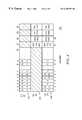
- FIG. 5shows a table 510 illustrating the virtual port assignment to the example as shown in FIGS. 3 and 4.
- this table 510is maintained in the switch which supports the virtual port function.
- the table conversion using this virtual port tableis performed in the switch so that the port configuration data maintenance in the network manager is reduced.
- switch 1 320is capable of handling up to 4 virtual ports.
- the number of 4 virtual portsis chosen for illustration purposes only. Other numbers of virtual ports can be similarly implemented.
- virtual port 27is assigned as a port representing the first trunking group comprising physical ports 3 , 4 and 7 of switch 1 320 .
- Virtual port 28is assigned as a port representing the second trunking group comprising physical ports 13 and 14 of switch 1 320 .
- virtual ports 29 and 30are not assigned with any physical ports by the user.
- FIG. 6shows a virtual port table 600 of another preferred embodiment according to the present invention.
- This table 600is similar to the table 500 as shown in FIG. 5 .
- the differenceis the additional third column.
- This third column of FIG. 6illustrates another feature of the present invention. That is, the present invention can also handle stacked switching systems.
- a stacked switching systemis a group of individual switches connected together as a stacked switching unit.
- a novel switching systemis disclosed with a copending patent application titled “Intelligent Stacked Switching System” by the same inventor Tomoyuki Sugihara, filed on Jun. 24, 1999, which is hereby incorporated by reference in its entirety.
- the tablecomprises an additional “Stacked ID” column which contains stacked unit IDs corresponding to the physical ports for trunking.
- the first entryrepresents all the virtual port information of virtual port 27 .
- virtual port 27is assigned as the first trunking group.
- virtual port 27comprises physical ports 3 , 4 and 7 from the first stacked unit (i.e. S 1 )
- the second entry of the tablerepresents all the virtual port information for virtual port 28 .
- virtual port 28is assigned as the second trunking group.
- the second trunking groupcomprises physical member ports 13 and 14 from the first stacked unit (i.e. S 1 ).
- virtual port 27 of stacked switching unit 1may comprises physical ports 1 , 5 of first stacked switching unit and ports 8 , 14 of the second stacked switching unit.
- the member ports information in each virtual portwill contain the stacked unit numbers, in addition to the port numbers as shown in FIG. 6 .
- virtual port 27 of stacked switching unit 1may contain the following information: 0101 , 0105 , 0208 , 0214 (wherein the first two digits refer to the stacked unit number and the final two digits refer to the physical port number, i.e. in an “uupp” format).
- a more sophisticated stacked controlleris needed to interpret the both the stacked unit ID and physical port numbers.
- FIG. 7is a flow chart showing the process in the node side to handle requests from the network manager.
- Step 710represents the beginning of the process.
- a SNMP requestis received by the node.
- a determinationis performed to determine whether the SNMP request is a virtual port request or a physical port request. This determination can be performed in the agent by comparing the requested port number with a port assignment table as shown in FIG. 5 or 6 .
- the port destination uuppindicates a virtual port is requested
- the appropriate conversionis performed according to the port assignment table so that the requested information from the corresponding physical ports are retrieved in Step 740 .
- the requested informationis then returned to the SNMP network manager in Step 760 .
- Step 750the corresponding physical port is accessed in Step 750 .
- the requested informationis then returned to the SNMP network manager in Step 770 .
- the processis ended in Step 780 .
- FIG. 8shows a block diagram of a preferred embodiment of each of the switches according to the present invention.
- each switching unit 800comprises a switching matrix 810 having eight bus ports 811 a,b,c,d,e,f,g,h:
- three of the eight bus portsare ethernet ports 811 a,b,c, and two of the eight bus ports are gigabit uplink ports 811 d,e.
- the remaining three bus ports 811 f,g,hare reserved for the stacking links between switching units.
- each of the three ethernet ports 811 a,b,csupports eight ethernet ports 10 Base-T/100 Base-TX ethernet ports. Each of them has eight MII fast internet ports and connects to two quad magnetic devices.
- each of these ethernet port controllersis supported by two separate memory ports for storing data management information such as address lookup data and input/output buffered data. Individual users can connect to the switching unit through any of these 24 ethernet ports. It should be noted that the present invention could be used in either the half-duplex or full-duplex connection.
- each of the two gigabit uplink ports 811 d,eis responsible for gigabit uplink. As shown in the figure, each of these two gigabit uplink ports 811 d,e is supported by three memory modules for storing address lookup data and buffered data packet.
- the remaining three ports 811 f,g,h of the switching matrix 810are specifically reserved for stacking purposes. By connecting one or more of these three ports 811 f,g,h to the stacking ports of other switching unit(s), a stacked switching system is created.
- the three set of the 10 BASE-T/100 BASE-TX ports as shown in the figureare numbered as ports 1 - 24 .
- Ports 25 and 26are two gigaports for uplink purpose.
- any combination of ports chosen from ports 1 - 26can be assigned as virtual ports 27 , 28 , 29 or 30 .
Landscapes
- Engineering & Computer Science (AREA)
- Computer Networks & Wireless Communication (AREA)
- Signal Processing (AREA)
- Data Exchanges In Wide-Area Networks (AREA)
- Paper (AREA)
- Coupling Device And Connection With Printed Circuit (AREA)
- Cameras Adapted For Combination With Other Photographic Or Optical Apparatuses (AREA)
- Catching Or Destruction (AREA)
- Multiple-Way Valves (AREA)
- Use Of Switch Circuits For Exchanges And Methods Of Control Of Multiplex Exchanges (AREA)
- Communication Control (AREA)
- Small-Scale Networks (AREA)
Abstract
Description
Claims (12)
Priority Applications (12)
| Application Number | Priority Date | Filing Date | Title |
|---|---|---|---|
| US09/350,748US6385197B1 (en) | 1999-07-09 | 1999-07-09 | Virtual port trunking method and apparatus |
| DE60031274TDE60031274T2 (en) | 1999-07-09 | 2000-07-06 | MULTIPLE CONNECTION METHOD AND DEVICE FOR VITUOUS PORTS |
| AT00948505TATE342622T1 (en) | 1999-07-09 | 2000-07-06 | MULTIPLE CONNECTION METHOD AND DEVICE FOR VITUAL PORTS |
| PCT/US2000/016310WO2001005101A1 (en) | 1999-07-09 | 2000-07-06 | A virtual port trunking method and apparatus |
| EP06021195AEP1760936B1 (en) | 1999-07-09 | 2000-07-06 | A virtual port trunking method and apparatus |
| DE60040700TDE60040700D1 (en) | 1999-07-09 | 2000-07-06 | Multi-port Virtual Port Method and Device |
| JP2001510195AJP3740060B2 (en) | 1999-07-09 | 2000-07-06 | Virtual port trunking method and apparatus |
| EP06021194.3AEP1750392B1 (en) | 1999-07-09 | 2000-07-06 | A virtual port trunking method and apparatus |
| EP00948505AEP1192760B1 (en) | 1999-07-09 | 2000-07-06 | A virtual port trunking method and apparatus |
| AT06021195TATE413037T1 (en) | 1999-07-09 | 2000-07-06 | MULTIPLE CONNECTION METHOD AND DEVICE FOR VIRTUAL PORTS |
| EP09006323.1AEP2088712B1 (en) | 1999-07-09 | 2000-07-06 | A virtual port trunking method and apparatus |
| AU61985/00AAU6198500A (en) | 1999-07-09 | 2000-07-06 | A virtual port trunking method and apparatus |
Applications Claiming Priority (1)
| Application Number | Priority Date | Filing Date | Title |
|---|---|---|---|
| US09/350,748US6385197B1 (en) | 1999-07-09 | 1999-07-09 | Virtual port trunking method and apparatus |
Publications (1)
| Publication Number | Publication Date |
|---|---|
| US6385197B1true US6385197B1 (en) | 2002-05-07 |
Family
ID=23378012
Family Applications (1)
| Application Number | Title | Priority Date | Filing Date |
|---|---|---|---|
| US09/350,748Expired - LifetimeUS6385197B1 (en) | 1999-07-09 | 1999-07-09 | Virtual port trunking method and apparatus |
Country Status (7)
| Country | Link |
|---|---|
| US (1) | US6385197B1 (en) |
| EP (4) | EP2088712B1 (en) |
| JP (1) | JP3740060B2 (en) |
| AT (2) | ATE342622T1 (en) |
| AU (1) | AU6198500A (en) |
| DE (2) | DE60031274T2 (en) |
| WO (1) | WO2001005101A1 (en) |
Cited By (35)
| Publication number | Priority date | Publication date | Assignee | Title |
|---|---|---|---|---|
| US20020071386A1 (en)* | 2000-12-07 | 2002-06-13 | Gronke Edward P. | Technique to provide automatic failover for channel-based communications |
| US20020143960A1 (en)* | 2000-08-02 | 2002-10-03 | Erez Goren | Virtual network generation system and method |
| US20020159446A1 (en)* | 2001-04-27 | 2002-10-31 | Foster Michael S. | Method and system for interswitch load balancing in a communications network |
| US20030028681A1 (en)* | 2001-08-02 | 2003-02-06 | International Business Machines Corporation | Apparatus and method for port sharing among a plurality of server processes |
| US20030212767A1 (en)* | 2002-05-07 | 2003-11-13 | Siew-Hong Yang-Huffman | Dynamic network configuration system and method |
| US6671739B1 (en)* | 2000-07-10 | 2003-12-30 | International Business Machines Corporation | Controlling network access by modifying packet headers at a local hub |
| US20040017816A1 (en)* | 2002-06-04 | 2004-01-29 | Prashanth Ishwar | Managing traffic in a multiport network node using logical ports |
| US6687751B1 (en)* | 2000-01-28 | 2004-02-03 | 3Com Corporation | Multi-point link aggregation spoofing |
| US20040246911A1 (en)* | 2001-10-17 | 2004-12-09 | Bonsma Erwin R | Network location management system |
| WO2005109718A1 (en)* | 2004-05-05 | 2005-11-17 | Gigamon Systems Llc | Asymmetric packet switch and a method of use |
| US20050265385A1 (en)* | 2004-05-28 | 2005-12-01 | International Business Machines Corp. | Virtual USB communications port |
| US20060195594A1 (en)* | 2004-12-22 | 2006-08-31 | Fujitsu Limited | Communication system |
| US20060194386A1 (en)* | 2005-02-25 | 2006-08-31 | Dell Products L.P. | Method and apparatus for supporting port aggregation of serial attached SCSI wide ports via virtual ports |
| US20060193266A1 (en)* | 2005-02-25 | 2006-08-31 | Ip Infusion, Inc. A Delaware Corporation | Hardware abstraction layer |
| ES2259264A1 (en)* | 2004-07-23 | 2006-09-16 | Mitsubishi Denki Kabushiki Kaisha | Network management system |
| US7145866B1 (en)* | 2001-03-01 | 2006-12-05 | Emc Corporation | Virtual network devices |
| US7197545B1 (en)* | 2000-08-28 | 2007-03-27 | Sanavigator, Inc. | Techniques for dynamically loading modules for devices discovered in a storage network |
| US20070214412A1 (en)* | 2002-09-30 | 2007-09-13 | Sanavigator, Inc. | Method and System for Generating a Network Monitoring Display with Animated Utilization Information |
| US7464174B1 (en) | 2005-03-07 | 2008-12-09 | Pericom Semiconductor Corp. | Shared network-interface controller (NIC) using advanced switching (AS) turn-pool routing field to select from among multiple contexts for multiple processors |
| US20090064181A1 (en)* | 2003-11-19 | 2009-03-05 | International Business Machines Corporation | Unobtrusive port and protocol sharing among server processes |
| KR100893259B1 (en)* | 2002-09-09 | 2009-04-17 | 주식회사 케이티 | Network management system and management method |
| US7606230B1 (en) | 2004-05-10 | 2009-10-20 | Marvell International Ltd. | Link aggregation for routed ports |
| US7889748B1 (en)* | 2007-02-02 | 2011-02-15 | Gigamon Llc. | Mapping a port on a packet switch appliance |
| US7917854B1 (en)* | 2002-10-28 | 2011-03-29 | Nortel Networks Limited | Telecommunications network administration graphical user interface |
| US20150172093A1 (en)* | 2013-12-16 | 2015-06-18 | Hitachi, Ltd. | Management apparatus, management method, and management program |
| US20160043902A1 (en)* | 2013-04-19 | 2016-02-11 | Hangzhou H3C Technologies Co., Ltd. | Topology discovery in a stacked switches system |
| US9537798B1 (en) | 2016-01-19 | 2017-01-03 | International Business Machines Corporation | Ethernet link aggregation with shared physical ports |
| US9628374B1 (en) | 2016-01-19 | 2017-04-18 | International Business Machines Corporation | Ethernet link aggregation with shared physical ports |
| CN111585815A (en)* | 2020-05-09 | 2020-08-25 | 浙江大华技术股份有限公司 | Port data acquisition method and device |
| US10756984B2 (en) | 2015-04-13 | 2020-08-25 | Wirepath Home Systems, Llc | Method and apparatus for creating and managing network device port VLAN configurations |
| US11068362B2 (en) | 2013-03-06 | 2021-07-20 | Fortinet, Inc. | High-availability cluster architecture and protocol |
| US11223531B2 (en) | 2010-07-06 | 2022-01-11 | Nicira, Inc. | Method and apparatus for interacting with a network information base in a distributed network control system with multiple controller instances |
| US11677588B2 (en)* | 2010-07-06 | 2023-06-13 | Nicira, Inc. | Network control apparatus and method for creating and modifying logical switching elements |
| CN117478502A (en)* | 2023-12-27 | 2024-01-30 | 中国石油集团东方地球物理勘探有限责任公司 | Dual positioning system and method |
| US11979280B2 (en) | 2010-07-06 | 2024-05-07 | Nicira, Inc. | Network control apparatus and method for populating logical datapath sets |
Families Citing this family (3)
| Publication number | Priority date | Publication date | Assignee | Title |
|---|---|---|---|---|
| US7388831B2 (en)* | 2000-07-26 | 2008-06-17 | Pluris, Inc. | Method and apparatus for bond management according to hierarchy |
| CN101023606A (en)* | 2004-06-30 | 2007-08-22 | 西门子公司 | Method and device for obtaining optical power level in PON |
| CN100442873C (en)* | 2005-12-08 | 2008-12-10 | 华为技术有限公司 | A data management system and method for a digital trunking system |
Citations (7)
| Publication number | Priority date | Publication date | Assignee | Title |
|---|---|---|---|---|
| US5509123A (en) | 1994-03-22 | 1996-04-16 | Cabletron Systems, Inc. | Distributed autonomous object architectures for network layer routing |
| US5737518A (en)* | 1996-07-31 | 1998-04-07 | Novell, Inc. | Method and apparatus for testing an object management system |
| US5764638A (en) | 1995-09-14 | 1998-06-09 | Level One Communications, Inc. | Method and apparatus for filtering and forwarding messages in a computer network using a last source address |
| EP0891061A2 (en) | 1997-07-08 | 1999-01-13 | Hewlett-Packard Company | Method and system for link level server/switch trunking |
| US5982753A (en)* | 1997-06-09 | 1999-11-09 | Fluke Corporation | Method of testing a switched local area network |
| US6108782A (en)* | 1996-12-13 | 2000-08-22 | 3Com Corporation | Distributed remote monitoring (dRMON) for networks |
| US6167403A (en)* | 1997-06-23 | 2000-12-26 | Compaq Computer Corporation | Network device with selectable trap definitions |
- 1999
- 1999-07-09USUS09/350,748patent/US6385197B1/ennot_activeExpired - Lifetime
- 2000
- 2000-07-06EPEP09006323.1Apatent/EP2088712B1/ennot_activeExpired - Lifetime
- 2000-07-06WOPCT/US2000/016310patent/WO2001005101A1/enactiveIP Right Grant
- 2000-07-06EPEP06021195Apatent/EP1760936B1/ennot_activeExpired - Lifetime
- 2000-07-06JPJP2001510195Apatent/JP3740060B2/ennot_activeExpired - Lifetime
- 2000-07-06AUAU61985/00Apatent/AU6198500A/ennot_activeAbandoned
- 2000-07-06DEDE60031274Tpatent/DE60031274T2/ennot_activeExpired - Lifetime
- 2000-07-06ATAT00948505Tpatent/ATE342622T1/ennot_activeIP Right Cessation
- 2000-07-06EPEP00948505Apatent/EP1192760B1/ennot_activeExpired - Lifetime
- 2000-07-06DEDE60040700Tpatent/DE60040700D1/ennot_activeExpired - Lifetime
- 2000-07-06ATAT06021195Tpatent/ATE413037T1/ennot_activeIP Right Cessation
- 2000-07-06EPEP06021194.3Apatent/EP1750392B1/ennot_activeExpired - Lifetime
Patent Citations (7)
| Publication number | Priority date | Publication date | Assignee | Title |
|---|---|---|---|---|
| US5509123A (en) | 1994-03-22 | 1996-04-16 | Cabletron Systems, Inc. | Distributed autonomous object architectures for network layer routing |
| US5764638A (en) | 1995-09-14 | 1998-06-09 | Level One Communications, Inc. | Method and apparatus for filtering and forwarding messages in a computer network using a last source address |
| US5737518A (en)* | 1996-07-31 | 1998-04-07 | Novell, Inc. | Method and apparatus for testing an object management system |
| US6108782A (en)* | 1996-12-13 | 2000-08-22 | 3Com Corporation | Distributed remote monitoring (dRMON) for networks |
| US5982753A (en)* | 1997-06-09 | 1999-11-09 | Fluke Corporation | Method of testing a switched local area network |
| US6167403A (en)* | 1997-06-23 | 2000-12-26 | Compaq Computer Corporation | Network device with selectable trap definitions |
| EP0891061A2 (en) | 1997-07-08 | 1999-01-13 | Hewlett-Packard Company | Method and system for link level server/switch trunking |
Non-Patent Citations (1)
| Title |
|---|
| "Dynamic Bandwidth Allocation for Striping and HUnt Groups in a Switced Network" Jun. 1993, IBM Technical Disclosure Bulletin. vol. 36 No. 06A, pp. 145, 146.* |
Cited By (90)
| Publication number | Priority date | Publication date | Assignee | Title |
|---|---|---|---|---|
| US6687751B1 (en)* | 2000-01-28 | 2004-02-03 | 3Com Corporation | Multi-point link aggregation spoofing |
| US6671739B1 (en)* | 2000-07-10 | 2003-12-30 | International Business Machines Corporation | Controlling network access by modifying packet headers at a local hub |
| US20020143960A1 (en)* | 2000-08-02 | 2002-10-03 | Erez Goren | Virtual network generation system and method |
| US7197545B1 (en)* | 2000-08-28 | 2007-03-27 | Sanavigator, Inc. | Techniques for dynamically loading modules for devices discovered in a storage network |
| US20020071386A1 (en)* | 2000-12-07 | 2002-06-13 | Gronke Edward P. | Technique to provide automatic failover for channel-based communications |
| US6888792B2 (en)* | 2000-12-07 | 2005-05-03 | Intel Corporation | Technique to provide automatic failover for channel-based communications |
| US7145866B1 (en)* | 2001-03-01 | 2006-12-05 | Emc Corporation | Virtual network devices |
| US20020184529A1 (en)* | 2001-04-27 | 2002-12-05 | Foster Michael S. | Communicating data through a network |
| US7068666B2 (en) | 2001-04-27 | 2006-06-27 | The Boeing Company | Method and system for virtual addressing in a communications network |
| US20020159453A1 (en)* | 2001-04-27 | 2002-10-31 | Foster Michael S. | Method and system for label table caching in a routing device |
| US20020188754A1 (en)* | 2001-04-27 | 2002-12-12 | Foster Michael S. | Method and system for domain addressing in a communications network |
| US20020159446A1 (en)* | 2001-04-27 | 2002-10-31 | Foster Michael S. | Method and system for interswitch load balancing in a communications network |
| US20030202536A1 (en)* | 2001-04-27 | 2003-10-30 | Foster Michael S. | Integrated analysis of incoming data transmissions |
| US20030204618A1 (en)* | 2001-04-27 | 2003-10-30 | Foster Michael S. | Using virtual identifiers to process received data routed through a network |
| US20020159389A1 (en)* | 2001-04-27 | 2002-10-31 | Foster Michael S. | Method and system for connection preemption in a communications network |
| US20020159452A1 (en)* | 2001-04-27 | 2002-10-31 | Foster Michael S. | Method and system for virtual addressing in a communications network |
| US20040004966A1 (en)* | 2001-04-27 | 2004-01-08 | Foster Michael S. | Using virtual identifiers to route transmitted data through a network |
| US7068667B2 (en) | 2001-04-27 | 2006-06-27 | The Boeing Company | Method and system for path building in a communications network |
| US20020159451A1 (en)* | 2001-04-27 | 2002-10-31 | Foster Michael S. | Method and system for path building in a communications network |
| US20020159468A1 (en)* | 2001-04-27 | 2002-10-31 | Foster Michael S. | Method and system for administrative ports in a routing device |
| US20020159456A1 (en)* | 2001-04-27 | 2002-10-31 | Foster Michael S. | Method and system for multicasting in a routing device |
| US7042877B2 (en) | 2001-04-27 | 2006-05-09 | The Boeing Company | Integrated analysis of incoming data transmissions |
| US6996058B2 (en) | 2001-04-27 | 2006-02-07 | The Boeing Company | Method and system for interswitch load balancing in a communications network |
| US20030028681A1 (en)* | 2001-08-02 | 2003-02-06 | International Business Machines Corporation | Apparatus and method for port sharing among a plurality of server processes |
| US6950873B2 (en)* | 2001-08-02 | 2005-09-27 | International Business Machines Corporation | Apparatus and method for port sharing a plurality of server processes |
| US7586853B2 (en)* | 2001-10-17 | 2009-09-08 | British Telecommunications Plc | Network location management system |
| US20040246911A1 (en)* | 2001-10-17 | 2004-12-09 | Bonsma Erwin R | Network location management system |
| US20030212767A1 (en)* | 2002-05-07 | 2003-11-13 | Siew-Hong Yang-Huffman | Dynamic network configuration system and method |
| US20040017816A1 (en)* | 2002-06-04 | 2004-01-29 | Prashanth Ishwar | Managing traffic in a multiport network node using logical ports |
| US7519056B2 (en) | 2002-06-04 | 2009-04-14 | Alcatel-Lucent Usa Inc. | Managing traffic in a multiport network node using logical ports |
| KR100893259B1 (en)* | 2002-09-09 | 2009-04-17 | 주식회사 케이티 | Network management system and management method |
| US8862998B2 (en) | 2002-09-30 | 2014-10-14 | Brocade Communications Systems, Inc. | Method and system for generating a network monitoring display with animated utilization information |
| US20070214412A1 (en)* | 2002-09-30 | 2007-09-13 | Sanavigator, Inc. | Method and System for Generating a Network Monitoring Display with Animated Utilization Information |
| US7917854B1 (en)* | 2002-10-28 | 2011-03-29 | Nortel Networks Limited | Telecommunications network administration graphical user interface |
| US20090064181A1 (en)* | 2003-11-19 | 2009-03-05 | International Business Machines Corporation | Unobtrusive port and protocol sharing among server processes |
| US8010683B2 (en)* | 2003-11-19 | 2011-08-30 | International Business Machines Corporation | Unobtrusive port and protocol sharing among server processes |
| US7440467B2 (en) | 2004-05-05 | 2008-10-21 | Gigamon Systems Llc | Asymmetric packet switch and a method of use |
| US20050265364A1 (en)* | 2004-05-05 | 2005-12-01 | Tom Gallatin | Asymmetric packet switch and a method of use |
| US9391925B2 (en) | 2004-05-05 | 2016-07-12 | Gigamon Inc. | Packet switch methods and systems |
| US8391286B2 (en) | 2004-05-05 | 2013-03-05 | Gigamon Llc | Packet switch methods |
| US20110216771A1 (en)* | 2004-05-05 | 2011-09-08 | Gigamon Systems Llc. | Asymmetric packet switch and a method of use |
| US20050254490A1 (en)* | 2004-05-05 | 2005-11-17 | Tom Gallatin | Asymmetric packet switch and a method of use |
| US7424018B2 (en) | 2004-05-05 | 2008-09-09 | Gigamon Systems Llc | Asymmetric packet switch and a method of use |
| US20050265248A1 (en)* | 2004-05-05 | 2005-12-01 | Tom Gallatin | Asymmetric packets switch and a method of use |
| US7436832B2 (en) | 2004-05-05 | 2008-10-14 | Gigamon Systems Llc | Asymmetric packets switch and a method of use |
| US9231889B2 (en) | 2004-05-05 | 2016-01-05 | Gigamon Inc. | Packet switch and method of use |
| US9225669B2 (en) | 2004-05-05 | 2015-12-29 | Gigamon Inc. | Packet switch and method of use |
| US9077656B2 (en) | 2004-05-05 | 2015-07-07 | Gigamon Inc. | Packet switch methods and systems |
| US20110044349A1 (en)* | 2004-05-05 | 2011-02-24 | Gigamon Llc. | Packet switch and method of use |
| WO2005109718A1 (en)* | 2004-05-05 | 2005-11-17 | Gigamon Systems Llc | Asymmetric packet switch and a method of use |
| US20090135835A1 (en)* | 2004-05-05 | 2009-05-28 | Gigamon Systems Llc | Asymmetric packet switch and a method of use |
| US7835358B2 (en) | 2004-05-05 | 2010-11-16 | Gigamon Llc. | Packet switch and method of use |
| US7792047B2 (en) | 2004-05-05 | 2010-09-07 | Gigamon Llc. | Asymmetric packet switch and a method of use |
| US7606230B1 (en) | 2004-05-10 | 2009-10-20 | Marvell International Ltd. | Link aggregation for routed ports |
| US8085778B1 (en) | 2004-05-10 | 2011-12-27 | Marvell International Ltd. | Voltage regulator |
| US7675937B2 (en) | 2004-05-28 | 2010-03-09 | International Business Machines Corporation | Virtual USB communications port |
| US7688851B2 (en) | 2004-05-28 | 2010-03-30 | International Business Machines Corporation | Virtual USB communications port |
| US20050265385A1 (en)* | 2004-05-28 | 2005-12-01 | International Business Machines Corp. | Virtual USB communications port |
| US20080232398A1 (en)* | 2004-05-28 | 2008-09-25 | International Business Machines Corporation | Virtual usb communications port |
| US20080181236A1 (en)* | 2004-05-28 | 2008-07-31 | International Business Machines Corporation | Virtual usb communications port |
| US7400648B2 (en) | 2004-05-28 | 2008-07-15 | International Business Machines Corporation | Virtual USB communications port |
| ES2259264A1 (en)* | 2004-07-23 | 2006-09-16 | Mitsubishi Denki Kabushiki Kaisha | Network management system |
| ES2259264B1 (en)* | 2004-07-23 | 2007-10-01 | Mitsubishi Denki Kabushiki Kaisha | NETWORK MANAGEMENT SYSTEM. |
| US8335843B2 (en)* | 2004-12-22 | 2012-12-18 | Fujitsu Limited | Communication system having multiple communication lines between a transmitter and a receiver |
| US20060195594A1 (en)* | 2004-12-22 | 2006-08-31 | Fujitsu Limited | Communication system |
| CN101129032B (en)* | 2005-02-25 | 2012-07-04 | Ip输入公司 | Hardware abstraction layer |
| WO2006091923A1 (en)* | 2005-02-25 | 2006-08-31 | Ip Infusion, Inc. | Hardware abstraction layer |
| US8254285B2 (en)* | 2005-02-25 | 2012-08-28 | Ip Infusion, Inc. | Hardware abstraction layer |
| US20060194386A1 (en)* | 2005-02-25 | 2006-08-31 | Dell Products L.P. | Method and apparatus for supporting port aggregation of serial attached SCSI wide ports via virtual ports |
| US20060193266A1 (en)* | 2005-02-25 | 2006-08-31 | Ip Infusion, Inc. A Delaware Corporation | Hardware abstraction layer |
| US7464174B1 (en) | 2005-03-07 | 2008-12-09 | Pericom Semiconductor Corp. | Shared network-interface controller (NIC) using advanced switching (AS) turn-pool routing field to select from among multiple contexts for multiple processors |
| US8570862B1 (en) | 2007-02-02 | 2013-10-29 | Gigamon Inc. | Mapping a port on a packet switch appliance |
| US7889748B1 (en)* | 2007-02-02 | 2011-02-15 | Gigamon Llc. | Mapping a port on a packet switch appliance |
| US11677588B2 (en)* | 2010-07-06 | 2023-06-13 | Nicira, Inc. | Network control apparatus and method for creating and modifying logical switching elements |
| US11979280B2 (en) | 2010-07-06 | 2024-05-07 | Nicira, Inc. | Network control apparatus and method for populating logical datapath sets |
| US12028215B2 (en) | 2010-07-06 | 2024-07-02 | Nicira, Inc. | Distributed network control system with one master controller per logical datapath set |
| US11876679B2 (en) | 2010-07-06 | 2024-01-16 | Nicira, Inc. | Method and apparatus for interacting with a network information base in a distributed network control system with multiple controller instances |
| US11539591B2 (en) | 2010-07-06 | 2022-12-27 | Nicira, Inc. | Distributed network control system with one master controller per logical datapath set |
| US11509564B2 (en) | 2010-07-06 | 2022-11-22 | Nicira, Inc. | Method and apparatus for replicating network information base in a distributed network control system with multiple controller instances |
| US11223531B2 (en) | 2010-07-06 | 2022-01-11 | Nicira, Inc. | Method and apparatus for interacting with a network information base in a distributed network control system with multiple controller instances |
| US11068362B2 (en) | 2013-03-06 | 2021-07-20 | Fortinet, Inc. | High-availability cluster architecture and protocol |
| US20160043902A1 (en)* | 2013-04-19 | 2016-02-11 | Hangzhou H3C Technologies Co., Ltd. | Topology discovery in a stacked switches system |
| US9769027B2 (en)* | 2013-04-19 | 2017-09-19 | Hewlett Packard Enterprise Development Lp | Topology discovery in a stacked switches system |
| US20150172093A1 (en)* | 2013-12-16 | 2015-06-18 | Hitachi, Ltd. | Management apparatus, management method, and management program |
| US10756984B2 (en) | 2015-04-13 | 2020-08-25 | Wirepath Home Systems, Llc | Method and apparatus for creating and managing network device port VLAN configurations |
| US9628374B1 (en) | 2016-01-19 | 2017-04-18 | International Business Machines Corporation | Ethernet link aggregation with shared physical ports |
| US9537798B1 (en) | 2016-01-19 | 2017-01-03 | International Business Machines Corporation | Ethernet link aggregation with shared physical ports |
| CN111585815A (en)* | 2020-05-09 | 2020-08-25 | 浙江大华技术股份有限公司 | Port data acquisition method and device |
| CN117478502B (en)* | 2023-12-27 | 2024-03-19 | 中国石油集团东方地球物理勘探有限责任公司 | Dual positioning system and method |
| CN117478502A (en)* | 2023-12-27 | 2024-01-30 | 中国石油集团东方地球物理勘探有限责任公司 | Dual positioning system and method |
Also Published As
| Publication number | Publication date |
|---|---|
| DE60031274D1 (en) | 2006-11-23 |
| EP2088712A1 (en) | 2009-08-12 |
| JP3740060B2 (en) | 2006-01-25 |
| EP1192760A1 (en) | 2002-04-03 |
| EP1760936A1 (en) | 2007-03-07 |
| EP1760936B1 (en) | 2008-10-29 |
| DE60040700D1 (en) | 2008-12-11 |
| EP1750392B1 (en) | 2014-11-12 |
| ATE342622T1 (en) | 2006-11-15 |
| EP2088712B1 (en) | 2014-12-03 |
| DE60031274T2 (en) | 2007-05-24 |
| EP1760936A9 (en) | 2008-02-13 |
| EP1750392A2 (en) | 2007-02-07 |
| JP2003504961A (en) | 2003-02-04 |
| WO2001005101A1 (en) | 2001-01-18 |
| WO2001005101A9 (en) | 2002-05-02 |
| EP1750392A3 (en) | 2007-03-07 |
| EP1192760B1 (en) | 2006-10-11 |
| AU6198500A (en) | 2001-01-30 |
| ATE413037T1 (en) | 2008-11-15 |
Similar Documents
| Publication | Publication Date | Title |
|---|---|---|
| US6385197B1 (en) | Virtual port trunking method and apparatus | |
| US6167052A (en) | Establishing connectivity in networks | |
| US5982753A (en) | Method of testing a switched local area network | |
| CN1756189B (en) | SNMP-based IP Network Topology Discovery Method | |
| US6898183B1 (en) | Method of determining a data link path in a managed network | |
| EP1309129A2 (en) | Method and apparatus for automatic load-balancing on multisegment devices | |
| US7020145B1 (en) | Network topology manager | |
| EP2748992A2 (en) | System and methods for managing network hardware address requests with a controller | |
| CN102714611B (en) | The configuration of network link in virtual connection environment | |
| US6954462B1 (en) | Method and apparatus for determining a multilayer switching path | |
| US7797634B2 (en) | Method and apparatus for displaying network fabric data | |
| US20040064538A1 (en) | System and method of a management information base (MIB) Autocast in a communications network | |
| Cisco | Product Overview | |
| Cisco | Product Overview | |
| Cisco | Product Overview | |
| Cisco | Product Overview | |
| Cisco | Product Overview | |
| Cisco | Product Overview | |
| Cisco | Product Overview | |
| Cisco | Product Overview | |
| Cisco | Product Overview | |
| Cisco | Configuring the Catalyst 3920 | |
| HK1100109A (en) | A virtual port trunking method and apparatus | |
| Cisco | Product Overview | |
| HK1100990A (en) | A virtual port trunking method and apparatus |
Legal Events
| Date | Code | Title | Description |
|---|---|---|---|
| AS | Assignment | Owner name:ALLIED TELESYN INTERNATIONAL CORP., CALIFORNIA Free format text:ASSIGNMENT OF ASSIGNORS INTEREST;ASSIGNOR:SUHIHARA, TOMOYUKI;REEL/FRAME:010345/0883 Effective date:19990722 | |
| STCF | Information on status: patent grant | Free format text:PATENTED CASE | |
| FPAY | Fee payment | Year of fee payment:4 | |
| AS | Assignment | Owner name:ALLIED TELESYN, INC., CALIFORNIA Free format text:CHANGE OF NAME;ASSIGNOR:ALLIED TELESYN INTERNATIONAL CORP.;REEL/FRAME:018296/0248 Effective date:20011128 Owner name:ALLIED TELESIS, INC., WASHINGTON Free format text:CHANGE OF NAME;ASSIGNOR:ALLIED TELESYN, INC.;REEL/FRAME:018296/0271 Effective date:20060104 | |
| AS | Assignment | Owner name:ALLIED TELESIS, INC., WASHINGTON Free format text:CHANGE OF NAME;ASSIGNOR:ALLIED TELESYN, INC.;REEL/FRAME:018350/0125 Effective date:20051220 | |
| AS | Assignment | Owner name:ARCHER CAPITAL FUND, L.P., NEW YORK Free format text:SECURITY AGREEMENT;ASSIGNORS:ALLIED TELESIS, INC.;ALLIED TELESIS CAPITAL CORP.;REEL/FRAME:019995/0087 Effective date:20071019 | |
| AS | Assignment | Owner name:ALLIED TELESIS, INC., WASHINGTON Free format text:CHANGE OF NAME;ASSIGNOR:ALLIED TELESYN, INC.;REEL/FRAME:020417/0305 Effective date:20051220 Owner name:ALLIED TELESIS, INC.,WASHINGTON Free format text:CHANGE OF NAME;ASSIGNOR:ALLIED TELESYN, INC.;REEL/FRAME:020417/0305 Effective date:20051220 | |
| AS | Assignment | Owner name:SILICON VALLEY BANK, CALIFORNIA Free format text:SECURITY AGREEMENT;ASSIGNOR:ALLIED TELESIS, INC.;REEL/FRAME:021669/0455 Effective date:20080915 | |
| FPAY | Fee payment | Year of fee payment:8 | |
| AS | Assignment | Owner name:ALLIED TELESIS INC, CALIFORNIA Free format text:RELEASE BY SECURED PARTY;ASSIGNOR:SILICON VALLEY BANK;REEL/FRAME:031362/0631 Effective date:20130828 | |
| FPAY | Fee payment | Year of fee payment:12 |