US6385184B2 - Base station apparatus and transmission power control method - Google Patents
Base station apparatus and transmission power control methodDownload PDFInfo
- Publication number
- US6385184B2 US6385184B2US09/306,397US30639799AUS6385184B2US 6385184 B2US6385184 B2US 6385184B2US 30639799 AUS30639799 AUS 30639799AUS 6385184 B2US6385184 B2US 6385184B2
- Authority
- US
- United States
- Prior art keywords
- data
- power control
- transmission power
- slot
- received
- Prior art date
- Legal status (The legal status is an assumption and is not a legal conclusion. Google has not performed a legal analysis and makes no representation as to the accuracy of the status listed.)
- Expired - Lifetime
Links
Images


Classifications
- H—ELECTRICITY
- H04—ELECTRIC COMMUNICATION TECHNIQUE
- H04W—WIRELESS COMMUNICATION NETWORKS
- H04W52/00—Power management, e.g. Transmission Power Control [TPC] or power classes
- H04W52/04—Transmission power control [TPC]
- H04W52/54—Signalisation aspects of the TPC commands, e.g. frame structure
- H—ELECTRICITY
- H04—ELECTRIC COMMUNICATION TECHNIQUE
- H04W—WIRELESS COMMUNICATION NETWORKS
- H04W52/00—Power management, e.g. Transmission Power Control [TPC] or power classes
- H04W52/04—Transmission power control [TPC]
- H04W52/06—TPC algorithms
- H04W52/08—Closed loop power control
- H—ELECTRICITY
- H04—ELECTRIC COMMUNICATION TECHNIQUE
- H04W—WIRELESS COMMUNICATION NETWORKS
- H04W52/00—Power management, e.g. Transmission Power Control [TPC] or power classes
- H04W52/04—Transmission power control [TPC]
- H04W52/06—TPC algorithms
- H04W52/10—Open loop power control
- H—ELECTRICITY
- H04—ELECTRIC COMMUNICATION TECHNIQUE
- H04W—WIRELESS COMMUNICATION NETWORKS
- H04W52/00—Power management, e.g. Transmission Power Control [TPC] or power classes
- H04W52/04—Transmission power control [TPC]
- H04W52/18—TPC being performed according to specific parameters
- H04W52/24—TPC being performed according to specific parameters using SIR [Signal to Interference Ratio] or other wireless path parameters
- H—ELECTRICITY
- H04—ELECTRIC COMMUNICATION TECHNIQUE
- H04W—WIRELESS COMMUNICATION NETWORKS
- H04W52/00—Power management, e.g. Transmission Power Control [TPC] or power classes
- H04W52/04—Transmission power control [TPC]
- H04W52/18—TPC being performed according to specific parameters
- H04W52/26—TPC being performed according to specific parameters using transmission rate or quality of service QoS [Quality of Service]
- H04W52/267—TPC being performed according to specific parameters using transmission rate or quality of service QoS [Quality of Service] taking into account the information rate
- H—ELECTRICITY
- H04—ELECTRIC COMMUNICATION TECHNIQUE
- H04W—WIRELESS COMMUNICATION NETWORKS
- H04W52/00—Power management, e.g. Transmission Power Control [TPC] or power classes
- H04W52/04—Transmission power control [TPC]
- H04W52/54—Signalisation aspects of the TPC commands, e.g. frame structure
- H04W52/58—Format of the TPC bits
- H—ELECTRICITY
- H04—ELECTRIC COMMUNICATION TECHNIQUE
- H04W—WIRELESS COMMUNICATION NETWORKS
- H04W88/00—Devices specially adapted for wireless communication networks, e.g. terminals, base stations or access point devices
- H04W88/02—Terminal devices
- H—ELECTRICITY
- H04—ELECTRIC COMMUNICATION TECHNIQUE
- H04W—WIRELESS COMMUNICATION NETWORKS
- H04W88/00—Devices specially adapted for wireless communication networks, e.g. terminals, base stations or access point devices
- H04W88/08—Access point devices
Definitions
- the present inventionrelates to base station apparatususes carrying out transmission power control in CDMA communications and their transmission power control methods.
- a CDMA (Code Division Multiple Access) systemis one of the multiple access system technologies used in radio communication systems using mobile telephones and portable telephones, etc. when a plurality of stations carry out communications simultaneously on a same frequency band.
- the CDMA systemimplements multiple accesses by spread spectrum communications in which information signals are transmitted with their spectrum spread over a sufficiently wide band relative to the original information bandwidth.
- a direct sequence systemis a system in which a spreading code which has a faster transmission rate than the transmission rate of an information signal is directly carried on the information signal at the time of spreading.
- signals from a plurality of mobile stationsare multiplexed on a same frequency area and same time zone.
- the CDMA system using direct sequencehas a so-called “near-far” problem.
- This “near-far” problemoccurs when a desired transmitting station is located far and another undesired transmitting station (interfering station) is near, which causes the reception power of a received signal from the interfering station to be greater than that from the desired transmitting station, preventing the stations using only processing gain (spreading gain) from suppressing correlation between spreading codes, which disables communications.
- processing gainspreading gain
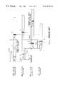
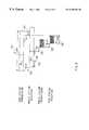
- FIG. 1shows a slot configuration on a time scale when carrying out conventional transmission power control.
- Pilot data 1is a signal with a fixed information pattern and is used by a mobile station to estimate channel conditions for demodulation and measure SIR (signal to interference ratio) and transmission power control data 2 is used as a transmission power control command.
- Signals on the uplink from a mobile station to a base station as well as signals on the downlink from a base station to a mobile stationare transmitted as slot cycle signals and a 1 ⁇ 2 slot timing offset (TShift) is added to the downlink to minimize a transmission power control delay.
- THziftslot timing offset
- a signal sent from a base stationis received by a mobile station with a propagation delay of TDelay (corresponding to the distance from the base station to the mobile station).
- the mobile stationmeasures reception SIR according to pilot data 4 at the start of a slot. Then, the mobile station compares this SIR measurement result with a given reference SIR and if the reception SIR is lower, generates a transmission power control bit which instructs the base station to increase transmission power, and if the reception SIR is higher, generates a transmission power control bit as a command to instruct the base station to lower transmission power.
- This transmission power control bitis embedded as transmission power control data 5 on the uplink and transmitted.
- a signal sent from the mobile stationis received by the base station with a delay of TDelay.
- the base stationdetects transmission power control data 6 and determines the transmission power value on the downlink from the result and reflects it in the transmission power at the start of the next downlink slot.
- a signal sent from the mobile stationis received by the base station with a delay of TDelay.
- the base stationmeasures SIR according to pilot data 7 at the start of a slot and compares the reception SIR and a reference SIR as in the case of the mobile station, generates a transmission power control bit which is a command to instruct whether to increase/decrease transmission power and embeds it in transmission power control data 8 on the downlink and transmits it.
- a signal sent from the base stationis received by the mobile station with a delay of TDelay.
- the mobile stationdetects transmission power control data 9 and determines the transmission power value on the uplink from the result and reflects it in the transmission power at the start of the next uplink slot.
- the uplink slothas a timing offset of 1 ⁇ 2 slot with respect to the downlink slot
- transmission power controlis carried out with one time slot control delay (the result of control 1 slot before is reflected) for both the downlink and uplink.
- signals 11 to 13 sent from the base stationare received by the mobile station with a propagation delay of TDelay (corresponding to the distance from the base station to the mobile station) and the mobile station measures the reception SIR from pilot data 14 at the start of a slot.
- the mobile stationcompares this SIR measurement result with a reference SIR and embeds the result as transmission power control data 15 on the uplink and transmits it.
- a signal sent from the mobile stationis received by the base station with a delay of TDelay.
- the base stationdetects transmission power control data 16 and determines the transmission power value of the downlink from the result and reflects it in the transmission power at the start of the next downlink slot.
- a signal sent from the mobile station on the uplinkis received by the base station with a delay of TDelay.
- the base stationmeasures SIR according to pilot data 17 at the start of a slot and compares the reception SIR with a reference SIR as in the case of the mobile station, generates a transmission power control bit which is a command to instruct whether to increase/decrease transmission power and embeds it in transmission power control data 18 on the downlink and transmits it.
- a signal sent from the base stationis received by the mobile station with a delay of TDelay.
- the mobile stationdetects transmission power control data 19 and determines the transmission power value on the uplink from the result and reflects it in the transmission power at the start of the next downlink slot.
- the ratios of the pilot data length and transmission power control bit length to the slot lengthmay increase, causing a transmission power control delay due to a closed loop to increase.
- a transmission power control delayincreases, transmission power control is not reflected in the next slot, disabling appropriate transmission power control according to changes in a communication environment.
- the inventorcame to come up with the present invention by discovering by focusing on a data slot configuration that adequately changing the arrangement of a slot configuration could prevent transmission power control from failing to catch the next slot when pilot data and transmission power control data are relatively long.
- the arrangement of the slot configurationis performed by taking into account a propagation delay from abase station to a mobile station, the pilot data length for measuring the quality of the received signal, and time factors that could possibly cause control delays including the processing time after the mobile station has received the last part of the pilot data until it measures the quality of the received signal and embeds transmission power control data, a propagation delay from the mobile station to the base station, and the processing time after the base station has received the transmission power control data until it detects the transmission power control data and changes the power, etc.
- FIG. 1is a slot configuration diagram of a signal transmitted/received at a high transmission rate in a conventional radio communication system
- FIG. 2is a slot configuration diagram of a signal transmitted/received at a low transmission rate in the conventional radio communication system
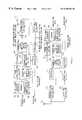
- FIG. 3is a block diagram showing the configuration of a radio communication system according to embodiments of the present invention.
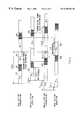
- FIG. 4is a slot configuration diagram of a signal transmitted/received by a base station apparatus and mobile station apparatus according to Embodiment 1 of the present invention
- FIG. 5is a slot configuration diagram of a signal transmitted/received by a base station apparatus and mobile station apparatus according to Embodiment 2 of the present invention
- FIG. 6is a slot configuration diagram of a signal transmitted/received by a base station apparatus and mobile station apparatus according to Embodiment 3 of the present invention.
- FIG. 7is a slot configuration diagram of a signal transmitted/received by a base station apparatus and mobile station apparatus according to Embodiment 4 of the present invention.
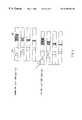
- FIG. 8is a slot configuration diagram of a signal transmitted/received by a base station apparatus and mobile station apparatus according to Embodiment 5 of the present invention.
- FIG. 9is a schematic showing the time necessary for transmission power control processing on the downlink according to the embodiments of the present invention.
- FIG. 10is a schematic showing the time necessary for transmission power control processing on the uplink according to the embodiments of the present invention.
- FIG. 3is a block diagram showing the configuration of a radio communication system according to Embodiment 1 of the present invention.
- This radio communication systemcomprises a base station apparatus and mobile station apparatus.
- transmission data to the mobile stationare input to encoder 102 for forward error correction(FEC) and encoding.
- the encoded datais input to frame configuration section 104 .
- Pilot signal generator 101generates pilot signals with fixed data patterns and outputs them to frame configuration section 104 .
- Frame configuration section 104arranges the output data of encoder 102 , a pilot signal from pilot signal generator 101 and a transmission power control bit which is the output of transmission power control bit generator 103 to the determined position, and outputs it to spreader 105 . This arrangement is determined by taking into account processing delays and propagation delays required for transmission power control. Furthermore, frame configuration section 104 provides a slot offset, that is, it shifts slots by a given time.
- Spreader 105carries out spreading processing and outputs the spread signal to transmission signal amplitude control section 106 .
- Transmission signal amplitude control section 106controls the amplitude of the input signal and outputs the signal to adder 107 .
- Adder 107adds up the output of transmission signal amplitude control section 106 and signals from the transmission section for other mobile stations and outputs the result to transmission RF section 108 .
- Transmission RF section 108carries out modulation and frequency conversion on the input and transmits the signal from antenna 109 .
- a signal of the mobile station received through antenna 109is subjected to frequency conversion and demodulation in reception RF section and output to correlator 111 and the reception processing section for other mobile stations.
- Correlator 111despreads the signal using the spreading code used for mobile station transmission, separates a desired wave signal and outputs it to decoder 112 and reception SIR measuring apparatus 113 .
- Decoder 112decodes the input and obtains received data.
- Reception SIR measuring apparatus 113measures reception SIR from the received signal and outputs the result to transmission power control bit generator 103 .
- Transmission power control bit generator 103compares the input reception SIR with a reference SIR and generates transmission power control data.
- the transmission power control data detected by decoder 112are output to transmission power control section 114 where the transmission power value is determined.
- This transmission power valueis sent to transmission signal amplitude control section 106 and transmission RF section 108 and the transmission power is controlled according to this transmission power value.
- the mobile station apparatushas the same structure as that of the base station apparatus except sections for multiplexing and distributing signals from other mobile stations and transmission signal amplitude control section 106 that controls the amplitude of a transmission signal by multiplexing. That is, pilot signal generator 101 to spreader 105 and adder 107 to antenna 109 correspond to antenna 115 to transmission power control section 126 , respectively and these sections operate identically.
- the slot configuration for the downlinkis the same as the conventional one. With respect to the slot configuration for the uplink, it is different from the conventional one in that pilot data are separated from transmission power control data in the slot, and is different in the offset between the uplink and the downlink.
- a signal sent from the base station(signal made up of pilot data 201 , transmission power control data 202 and data 203 ) is received by the mobile station with a propagation delay of TDelay (corresponding to the distance from the base station to the mobile station).
- the mobile stationmeasures reception SIR according to pilot data 204 at the start of a slot. It compares this SIR measurement result with a reference SIR and if the reception SIR is lower, generates a transmission power control bit as a command to instruct the base station to increase transmission power, and if the reception SIR is higher, generates a transmission power control bit as a command to instruct the base station to lower transmission power.
- This transmission power control bitis embedded as transmission power control data 205 on the uplink and transmitted.
- data locations in the slotare determined by taking account of a delay. More specifically, data are located in such a way that pilot data 204 is separated from transmission power control data 205 , that is, some data are inserted between the pilot data and transmission power control data. Furthermore, the slot is shifted by TShift. This allows the transmission power control bit obtained by the SIR measurement to be included in transmission power control data 205 on the uplink without delays. In other words, the transmission power control data on the uplink can be reflected in the slot without delays.
- a signal sent from the mobile stationis received by the base station with a delay of TDelay.
- the base stationdetects transmission power control data 206 and determines the transmission power value on the downlink from the result and reflects it in the transmission power at the start of the next downlink slot.
- a signal sent from the mobile stationis received by the base station with a delay of TDelay.
- the base-stationmeasures SIR from pilot data 207 at the start of a slot and compares the reception SIR with a reference SIR as in the case of the mobile station, generates a transmission power control bit which is a command to instruct whether to increase or decrease transmission power and embeds it in transmission power control data 208 on the downlink and transmits it.
- the slot sent from the mobile stationhas a configuration in which the pilot data is separated from the transmission power control data and thus the transmission power control bit based on the SIR measurement result of pilot data 207 can be embedded in transmission power control data 208 of the next slot. Therefore, the transmission power control data on the downlink can be reflected in the slot without delays.
- a signal sent from the base stationis received by the mobile station with a delay of TDelay.
- the mobile stationdetects transmission power control data 209 and determines the transmission power value on the uplink from the result and reflects it in the transmission power at the start of the next uplink slot.
- the radio communication systemplaces the pilot data separate from the transmission power control data in a slot for the uplink and provides an appropriate slot offset between the uplink and downlink, which allows the pilot data and transmission power control data locations to be determined adequately. It also allows the slot locational relationship between the uplink and downlink to be arranged adequately, making it possible to minimize control delays in closed-loop transmission power control at various transmission rates and suppress deterioration of the measurement accuracy caused by shortening the time for measuring the quality of the received signal.
- the present embodimentis capable of implementing a control delay of closed-loop transmission power control in one time slot for both the uplink and downlink without reducing the SIR measurement time even for low rate transmission.
- FIG. 5is a slot configuration diagram of a signal transmitted/received by a radio communication system according to Embodiment 2 of the present invention.
- the slot configuration for the uplinkis the same as the conventional one, but the slot configuration for the downlink is different from that of Embodiment 1 in that the pilot data are separated from the transmission power control data in the slot, and is different from Embodiment 1 in the slot offset between the downlink and uplink. It performs transmission power control in the same way as for Embodiment 1.
- the base stationdetermines data locations in the slot by taking delays into account. More specifically, data are located in such a way that pilot data 301 is separated from transmission power control data 302 , that is, data 303 are inserted between pilot data 301 and transmission power control data 302 .
- the mobile stationmeasures SIR using received pilot data 304 and embeds the result in transmission power control data 305 . Furthermore, the slot is shifted by TShift. This allows transmission power control of the next slot to be performed without delays according to the transmission power control value of transmission power control data 308 . As a result, the transmission power control data of the uplink can be reflected in the slot without delays.
- the base stationmeasures SIR according to pilot data 307 at the start of a slot and generates a transmission power control bit according to the result, embeds it in transmission power control data 302 on the downlink and transmits it.
- the slot sent to the mobile stationhas such a configuration that the pilot data are separated from the transmission power control data, making it possible to embed the transmission power control bit based on the SIR measurement result of pilot data 307 in transmission power control data 302 of the next slot. Therefore, the transmission power control data of the uplink can be reflected in the next slot without delays.
- the base stationdetects transmission power control data 306 , determines the transmission power value of the downlink from this result and reflects it in the transmission power at the start of the downlink slot.
- the radio communication systemplaces the pilot data separate from the transmission power control data for the downlink even for low rate transmission and adequately provides a slot offset between the uplink and downlink, making it possible to implement control delays in closed-loop transmission power control with one time slot without reducing the SIR measurement time.
- FIG. 6is a slot configuration diagram of a signal transmitted/received by a radio communication system according to Embodiment 3 of the present invention.
- the present embodimentplaces pilot data separate from the transmission power control data in a slot for both the uplink and downlink and provides an appropriate slot offset between the uplink and downlink.
- the present embodimentalso performs transmission power control using the same method as that in Embodiment 1.
- the base station and mobile stationdetermine data locations in the slot by taking delays into account. More specifically, data are located in such a way that pilot data 401 is separated from transmission power control data 402 , that is, data 403 is inserted between pilot data 401 and transmission power control data 402 .
- the mobile stationmeasures SIR using received pilot data 404 and embeds the result in transmission power control data 405 . Furthermore, the slot is shifted by TShift. This allows transmission power control of the next slot to be performed without delays according to the transmission power control value of transmission power control data 406 . As a result, the transmission power control data of the uplink can be reflected in the slot without delays.
- the base stationmeasures SIR according to pilot data 407 at the start of a slot and generates a transmission power control bit according to the result, embeds it in transmission power control data 408 on the downlink and transmits it.
- the slot sent to the mobile stationhas such a configuration that the pilot data are separate from the transmission power control data, making it possible to reflect the transmission power control bit of transmission power control data 409 based on the SIR measurement result of pilot data 407 in the start of the next uplink slot.
- the radio communication systemplaces the pilot data separate from the transmission power control data for the downlink even for low rate transmission and adequately provides a slot offset between the uplink and downlink, making it possible to implement control delays in closed-loop transmission power control with one time slot without reducing the SIR measurement time for both the uplink and downlink.
- FIG. 7is a slot configuration diagram of a signal transmitted/received in a radio communication system according to Embodiment 4 of the present invention.
- data 501is assigned to Ich on the uplink
- control informationsuch as pilot data 502 , transmission power control data 503 and rate information 504 is assigned to Qch.
- the percentage of the pilot datais greater no matter what the transmission rate may be.
- the present embodimentalso places the pilot data separate from the transmission power control data of the uplink, provides an appropriate slot offset between the uplink and downlink and performs transmission power control through operations similar to those in Embodiment 1.
- the transmission/reception apparatuscan, by placing the pilot data separate from the transmission power control data and providing an appropriate slot offset between the uplink and downlink, minimize control delays in closed-loop transmission power control for both the uplink and downlink without reducing the SIR measurement time.
- FIG. 8is a slot configuration diagram of a signal transmitted/received by a radio communication system according to Embodiment 5 of the present invention.
- the absolute times of pilot data 601 and transmission power control data 602vary depending on the rate of the slot configuration. Therefore, the ratios of the pilot data and transmission power control data to the slot each vary depending on the transmission rate.
- slots with other transmission ratesare formed with their pilot data and transmission power control data locations matched with those of the slot configuration with the lowest possible transmission rate. That is, as shown in FIG. 8, slots are configured in such a way that the distance (data length) between pilot data 601 and the transmission power control data is kept constant for different transmission rates. At this time, it is possible to perform transmission power control in the same way as for the embodiment above by carrying out the same processing as that in the above embodiment for all possible transmission rates.
- the transmission/reception apparatuscan, for different transmission rates, minimize control delays in closed-loop transmission power control for both the uplink and downlink while keeping the slot offset between the uplink and downlink constant, without reducing the SIR measurement time. It also eliminates the necessity of changing a slot offset between the uplink and downlink for communications with different transmission rates, eliminating the necessity of complicated processing by changing transmission rates.
- the present embodimenttakes as an example the case where slots are configured in such a way that the distance (data length) between pilot data 601 and the transmission power control data is kept constant for different transmission rates.
- the effects of the present embodimentwill be further enhanced if data locations are determined in such a way that other pilot data and transmission power control data locations are shifted so as to fit within the pilot data length and transmission power control data length corresponding to the lowest transmission rate.
- FIG. 9shows the time required for processing transmission power control on the downlink.
- the possible control delay timecan be expressed in the following expression.
- Transmission power control delay time (downlink)TDelay+TPLMS+TMS 1 +TDelay+TTPCBS+TBS 1
- FIG. 10shows the processing time required for transmission power control processing on the uplink.
- the possible control delay timecan be expressed in the following expression.
- Transmission power control delay time (uplink)TDelay+TPLBS+TBS 2 +TDelay+TTPCMS+TMS 2
- the pilot data lengthis the data length to measure SIR, and if SIR is also measured using data other than the pilot data this value includes that length.
- the slot configuration method in the present embodimentallows the optimal slot configuration to be assigned with a minimum control delay in closed-loop transmission power control.
- Embodiments 1 to 5 aboveare explained by taking as an example the case where SIR is used as the quality of the received signal, but the present invention can also be implemented in the same way using other parameters as the quality of the received signal.
- the base station apparatus and transmission power control method of the present inventionplaces pilot data and transmission power control data independently of each other in a transmission/reception apparatus which carries out closed-loop type transmission power control and places slots by providing an offset in the slot locational relationship between the uplink and downlink, making it possible to minimize control delays in closed-loop transmission power control at various transmission rates and suppress deterioration in the measurement accuracy caused by reducing the SIR measurement time.
Landscapes
- Engineering & Computer Science (AREA)
- Computer Networks & Wireless Communication (AREA)
- Signal Processing (AREA)
- Quality & Reliability (AREA)
- Mobile Radio Communication Systems (AREA)
- Cable Transmission Systems, Equalization Of Radio And Reduction Of Echo (AREA)
Abstract
Description
Claims (15)
Priority Applications (4)
| Application Number | Priority Date | Filing Date | Title |
|---|---|---|---|
| US09/648,753US6487188B1 (en) | 1998-05-08 | 2000-08-28 | Radio communication system, mobile station apparatus, base station apparatus, and transmission power control method |
| US09/649,005US6526032B1 (en) | 1998-05-08 | 2000-08-28 | Base station apparatus and transmission power control method |
| US09/648,754US6590883B1 (en) | 1998-05-08 | 2000-08-28 | Base station apparatus and transmission power control method |
| US10/022,214US6490263B2 (en) | 1998-05-08 | 2001-12-20 | Radio communication apparatus and radio communication method |
Applications Claiming Priority (2)
| Application Number | Priority Date | Filing Date | Title |
|---|---|---|---|
| JP10-126225 | 1998-05-08 | ||
| JP12622598AJP3286247B2 (en) | 1998-05-08 | 1998-05-08 | Wireless communication system |
Related Child Applications (5)
| Application Number | Title | Priority Date | Filing Date |
|---|---|---|---|
| US09/648,753ContinuationUS6487188B1 (en) | 1998-05-08 | 2000-08-28 | Radio communication system, mobile station apparatus, base station apparatus, and transmission power control method |
| US09/648,754ContinuationUS6590883B1 (en) | 1998-05-08 | 2000-08-28 | Base station apparatus and transmission power control method |
| US09/649,005ContinuationUS6526032B1 (en) | 1998-05-08 | 2000-08-28 | Base station apparatus and transmission power control method |
| US09/885,822ContinuationUS6367305B2 (en) | 1999-05-07 | 2001-06-20 | System for anchoring frames to a platform |
| US10/022,214ContinuationUS6490263B2 (en) | 1998-05-08 | 2001-12-20 | Radio communication apparatus and radio communication method |
Publications (2)
| Publication Number | Publication Date |
|---|---|
| US20010046219A1 US20010046219A1 (en) | 2001-11-29 |
| US6385184B2true US6385184B2 (en) | 2002-05-07 |
Family
ID=14929863
Family Applications (5)
| Application Number | Title | Priority Date | Filing Date |
|---|---|---|---|
| US09/306,397Expired - LifetimeUS6385184B2 (en) | 1998-05-08 | 1999-05-06 | Base station apparatus and transmission power control method |
| US09/649,005Expired - LifetimeUS6526032B1 (en) | 1998-05-08 | 2000-08-28 | Base station apparatus and transmission power control method |
| US09/648,753Expired - LifetimeUS6487188B1 (en) | 1998-05-08 | 2000-08-28 | Radio communication system, mobile station apparatus, base station apparatus, and transmission power control method |
| US09/648,754Expired - LifetimeUS6590883B1 (en) | 1998-05-08 | 2000-08-28 | Base station apparatus and transmission power control method |
| US10/022,214Expired - LifetimeUS6490263B2 (en) | 1998-05-08 | 2001-12-20 | Radio communication apparatus and radio communication method |
Family Applications After (4)
| Application Number | Title | Priority Date | Filing Date |
|---|---|---|---|
| US09/649,005Expired - LifetimeUS6526032B1 (en) | 1998-05-08 | 2000-08-28 | Base station apparatus and transmission power control method |
| US09/648,753Expired - LifetimeUS6487188B1 (en) | 1998-05-08 | 2000-08-28 | Radio communication system, mobile station apparatus, base station apparatus, and transmission power control method |
| US09/648,754Expired - LifetimeUS6590883B1 (en) | 1998-05-08 | 2000-08-28 | Base station apparatus and transmission power control method |
| US10/022,214Expired - LifetimeUS6490263B2 (en) | 1998-05-08 | 2001-12-20 | Radio communication apparatus and radio communication method |
Country Status (9)
| Country | Link |
|---|---|
| US (5) | US6385184B2 (en) |
| EP (6) | EP1418683A1 (en) |
| JP (1) | JP3286247B2 (en) |
| KR (6) | KR100340360B1 (en) |
| CN (3) | CN1893306B (en) |
| CA (1) | CA2270798C (en) |
| DE (5) | DE69914828T2 (en) |
| MY (1) | MY124604A (en) |
| SG (1) | SG92636A1 (en) |
Cited By (22)
| Publication number | Priority date | Publication date | Assignee | Title |
|---|---|---|---|---|
| US6487188B1 (en)* | 1998-05-08 | 2002-11-26 | Matsushita Electric Industrial Co., Ltd. | Radio communication system, mobile station apparatus, base station apparatus, and transmission power control method |
| US20020176362A1 (en)* | 2001-03-21 | 2002-11-28 | Lg Electronics Inc. | Method for retransmitting data through a reverse link in packet data communication system using automatic repeat request |
| US20030032431A1 (en)* | 2001-08-13 | 2003-02-13 | Samsung Electronics Co., Ltd. | Method of supporting reverse FCH gating in base station of a mobile communication system |
| US6654358B1 (en)* | 1998-07-07 | 2003-11-25 | Samsung Electronics Co., Ltd. | Method for transmitting power control signal in mobile communication system |
| US20040052229A1 (en)* | 2002-09-12 | 2004-03-18 | Interdigital Technology Corporation | System for efficient recovery of Node-B buffered data following MAC layer reset |
| US6747969B1 (en)* | 1999-11-23 | 2004-06-08 | Olaf Hirsch | Transmission gap interference measurement |
| US20040110475A1 (en)* | 2002-12-09 | 2004-06-10 | Victor Korol | Method and apparatus to control power of transmitter |
| US20040165554A1 (en)* | 2002-04-05 | 2004-08-26 | Interdigital Technology Corporation | System for efficient recovery of node B buffered data following serving high speed downlink shared channel cell change |
| US20050058154A1 (en)* | 2001-03-21 | 2005-03-17 | Lg Electronics Inc. | Packet transmitting method in mobile communication system |
| RU2253947C2 (en)* | 2002-05-11 | 2005-06-10 | Самсунг Электроникс Ко.,Лтд | Method for determining displacement of power hs-pdsch in asynchronous cdma movile communications system and appropriate method for transferring required information |
| KR100515416B1 (en)* | 2002-12-05 | 2005-09-15 | 엘지전자 주식회사 | Common power control channel control method in mobile communication system |
| US20060023629A1 (en)* | 2004-07-16 | 2006-02-02 | Samsung Electronics Co., Ltd. | Method and apparatus for performing autonomous transmission in a mobile communication system for supporting an enhanced uplink dedicated channel |
| US6999427B1 (en)* | 1999-07-21 | 2006-02-14 | Ntt Docomo, Inc. | CDMA reception apparatus and received signal power measuring apparatus in CDMA mobile communication system |
| US7089028B1 (en)* | 1999-01-16 | 2006-08-08 | Koninklijke Philips Electronics N.V. | Radio communication system |
| US20080214196A1 (en)* | 2007-01-22 | 2008-09-04 | Qualcomm Incorporated | Techniques for high data rates with improved channel reference |
| US20100041429A1 (en)* | 2008-08-18 | 2010-02-18 | Qualcomm, Incorporated | System and method for processing power control commands in a wireless communication system |
| US20100049021A1 (en)* | 2006-03-28 | 2010-02-25 | Jina Arvind N | Devices, systems, methods and tools for continuous analyte monitoring |
| US20100118840A1 (en)* | 2007-08-02 | 2010-05-13 | Fujitsu Limited | Pilot arrangement method in mobile radio communication system and transmitter/receiver adopting same |
| USRE41444E1 (en) | 1997-12-30 | 2010-07-20 | Panasonic Corporation | CDMA radio multiplex transmitting device and a CDMA radio multiplex receiving device |
| US20110212744A1 (en)* | 2010-02-26 | 2011-09-01 | Hitachi, Ltd. | Transmit power control method for radio communication system and radio base station device |
| US20140241288A1 (en)* | 2001-03-29 | 2014-08-28 | Samsung Electronics Co., Ltd. | Method of controlling reverse transmission in a mobile communication system |
| US20170006554A1 (en)* | 2011-06-13 | 2017-01-05 | Interdigital Patent Holdings, Inc. | Method for controlling transmit power of a mobile station |
Families Citing this family (64)
| Publication number | Priority date | Publication date | Assignee | Title |
|---|---|---|---|---|
| US6885652B1 (en) | 1995-06-30 | 2005-04-26 | Interdigital Technology Corporation | Code division multiple access (CDMA) communication system |
| US7020111B2 (en) | 1996-06-27 | 2006-03-28 | Interdigital Technology Corporation | System for using rapid acquisition spreading codes for spread-spectrum communications |
| US7123600B2 (en) | 1995-06-30 | 2006-10-17 | Interdigital Technology Corporation | Initial power control for spread-spectrum communications |
| US7929498B2 (en)* | 1995-06-30 | 2011-04-19 | Interdigital Technology Corporation | Adaptive forward power control and adaptive reverse power control for spread-spectrum communications |
| ZA965340B (en) | 1995-06-30 | 1997-01-27 | Interdigital Tech Corp | Code division multiple access (cdma) communication system |
| CN1136741C (en)* | 1996-11-27 | 2004-01-28 | 株式会社日立制作所 | Transmission power control method for mobile communication system, mobile terminal and base station |
| US20020051434A1 (en)* | 1997-10-23 | 2002-05-02 | Ozluturk Fatih M. | Method for using rapid acquisition spreading codes for spread-spectrum communications |
| JP3881770B2 (en)* | 1998-03-10 | 2007-02-14 | 松下電器産業株式会社 | Mobile station apparatus and communication method |
| JP2000252952A (en)* | 1999-03-02 | 2000-09-14 | Nec Corp | Machine and method for receiving cdma |
| JP2000341212A (en)* | 1999-05-27 | 2000-12-08 | Nec Corp | Cdma base station transmission power control circuit, base station device with same, and tpc timing method |
| JP4481545B2 (en)* | 1999-09-30 | 2010-06-16 | テレフオンアクチーボラゲット エル エム エリクソン(パブル) | Power control method and power control apparatus |
| KR100407940B1 (en)* | 1999-10-28 | 2003-12-01 | 엘지전자 주식회사 | Power control method for common packet channel |
| JP2001186082A (en)* | 1999-12-24 | 2001-07-06 | Matsushita Electric Ind Co Ltd | CDMA mobile communication system and method |
| ATE255789T1 (en)* | 2000-02-08 | 2003-12-15 | Cit Alcatel | METHOD FOR SETTING A TRANSMISSION QUALITY SET VALUE FOR TRANSMIT POWER CONTROL IN A MOBILE RADIO TRANSMISSION SYSTEM |
| JP2001320326A (en)* | 2000-03-03 | 2001-11-16 | Sony Corp | Communication system, communication method and equipment |
| SG109450A1 (en)* | 2000-04-06 | 2005-03-30 | Ntt Docomo Inc | Multicast signal transmission power control method and base station using the same |
| KR20010107139A (en)* | 2000-05-25 | 2001-12-07 | 박종섭 | Appartus for controlling forward link power applied orthogonal transmit diversity in mobile communication system |
| EP1168654B1 (en)* | 2000-06-28 | 2006-08-16 | Samsung Electronics Co. Ltd. | Pilot channel power measurement means for a mobile station in asynchronous CDMA communication system |
| KR100678150B1 (en)* | 2000-06-29 | 2007-02-01 | 삼성전자주식회사 | Link adaptation system and method for code division multiple access system |
| JP3479836B2 (en) | 2000-09-18 | 2003-12-15 | 日本電気株式会社 | CDMA receiver |
| US8842642B2 (en) | 2000-10-19 | 2014-09-23 | Ipr Licensing, Inc. | Transmitting acknowledgement messages using a staggered uplink time slot |
| US7433340B1 (en)* | 2000-10-19 | 2008-10-07 | Interdigital Technology Corporation | Staggering forward and reverse wireless channel allocation timing |
| US6947748B2 (en) | 2000-12-15 | 2005-09-20 | Adaptix, Inc. | OFDMA with adaptive subcarrier-cluster configuration and selective loading |
| SE0004923D0 (en)* | 2000-12-29 | 2000-12-29 | Ericsson Telefon Ab L M | Method and system of transmission power control |
| US6725055B2 (en)* | 2001-01-05 | 2004-04-20 | Telefonaktiebolaget Lm Ericsson (Publ) | SIR estimation using delay time of power control commands |
| JP3838487B2 (en)* | 2001-08-10 | 2006-10-25 | 株式会社エヌ・ティ・ティ・ドコモ | Radio communication system, communication terminal apparatus, base station apparatus, and transmission power control method |
| DE60235638D1 (en)* | 2001-10-20 | 2010-04-22 | Korea Electronics Telecomm | PERFORMANCE CONTROL DEVICE WITH CLOSED LOOP FOR A MOBILE SATELLITE COMMUNICATION SYSTEM AND METHOD THEREFOR |
| SG110012A1 (en)* | 2001-12-28 | 2005-04-28 | Ntt Docomo Inc | Radio communication system, base station, relay station, mobile station, and packet transmission control method |
| KR100547848B1 (en)* | 2002-01-16 | 2006-02-01 | 삼성전자주식회사 | Method and apparatus for forward channel state information transmission and reception in multi-carrier mobile communication system |
| EP1511340A1 (en)* | 2002-05-31 | 2005-03-02 | Mitsubishi Denki Kabushiki Kaisha | Communication system |
| DE60319089T2 (en) | 2002-06-06 | 2009-03-26 | Ntt Docomo, Inc. | PACKAGE COMMUNICATION SYSTEM, PACKAGE COMMUNICATION METHOD, BASIC STATION, MOBILE STATION, CONTROLLER AND PACKAGE COMMUNICATION PROGRAM |
| US20040081131A1 (en) | 2002-10-25 | 2004-04-29 | Walton Jay Rod | OFDM communication system with multiple OFDM symbol sizes |
| US8208364B2 (en)* | 2002-10-25 | 2012-06-26 | Qualcomm Incorporated | MIMO system with multiple spatial multiplexing modes |
| US7986742B2 (en) | 2002-10-25 | 2011-07-26 | Qualcomm Incorporated | Pilots for MIMO communication system |
| US8320301B2 (en) | 2002-10-25 | 2012-11-27 | Qualcomm Incorporated | MIMO WLAN system |
| KR20040047348A (en)* | 2002-11-29 | 2004-06-05 | 유티스타콤코리아 유한회사 | Method for controlling access channel of mobile station |
| US7092731B2 (en)* | 2003-03-06 | 2006-08-15 | Lucent Technologies Inc. | Method for improving capacity of a reverse link channel in a wireless network |
| CN1875655B (en)* | 2003-10-02 | 2010-12-01 | 高通股份有限公司 | System and method for exchanging control data using multiple slot formats |
| US7474643B2 (en)* | 2003-10-02 | 2009-01-06 | Qualcomm Incorporated | Systems and methods for communicating control data using multiple slot formats |
| DE60330405D1 (en)* | 2003-10-07 | 2010-01-14 | Ericsson Telefon Ab L M | METHOD AND SYSTEM FOR TRANSMISSION CONTROL |
| US9473269B2 (en) | 2003-12-01 | 2016-10-18 | Qualcomm Incorporated | Method and apparatus for providing an efficient control channel structure in a wireless communication system |
| JP4967658B2 (en)* | 2004-08-11 | 2012-07-04 | 日本電気株式会社 | Pilot signal transmission method and radio communication system capable of measuring reception quality with high accuracy |
| GB2417167B (en)* | 2004-08-13 | 2007-02-14 | Ipwireless Inc | Apparatus and method for communicating user equipment specific information in cellular communication system |
| CN1324824C (en)* | 2004-11-19 | 2007-07-04 | 中兴通讯股份有限公司 | Mapping method for terminal synchronous control command in multiple time slot communication system |
| KR20060063632A (en)* | 2004-12-03 | 2006-06-12 | 삼성전자주식회사 | Apparatus and Method for Allocating Pilot Tone Power in Mobile Communication System |
| WO2007020575A1 (en)* | 2005-08-16 | 2007-02-22 | Koninklijke Philips Electronics N.V. | Format adaptation of a control channel for discontinuous data transmission |
| KR100913089B1 (en)* | 2006-02-07 | 2009-08-21 | 엘지전자 주식회사 | Method for Transmitting Pilot for Multiple Carrier System |
| US7853281B2 (en)* | 2006-04-14 | 2010-12-14 | Qualcomm Incorporated | Methods and apparatus for tracking wireless terminal power information |
| US20080039128A1 (en)* | 2006-08-09 | 2008-02-14 | Telefonaktiebolaget Lm Ericsson (Publ) | Propagation delay based transmit power control |
| CN101507170B (en)* | 2006-08-25 | 2012-12-26 | 高通股份有限公司 | CDMA wireless communication systems |
| WO2008147150A1 (en)* | 2007-05-30 | 2008-12-04 | Electronics And Telecommunications Research Institute | Radio resource reallocating method for circuit mode |
| CN101359937B (en)* | 2007-08-01 | 2012-07-18 | 中兴通讯股份有限公司 | Enhanced Uplink Power Control Method |
| TWI407722B (en)* | 2008-04-30 | 2013-09-01 | Ind Tech Res Inst | Method for operation of synchronous harq in a wireless communication system |
| US8248973B2 (en)* | 2008-04-30 | 2012-08-21 | Industrial Technology Research Institute | Method for operation of synchronous HARQ in a wireless communication system |
| JP5359254B2 (en) | 2008-12-19 | 2013-12-04 | 富士通株式会社 | Transmission power control information setting method |
| EP2312279A1 (en)* | 2009-10-07 | 2011-04-20 | Dresser Wayne AB | Fluid meter with pressure protection |
| US8724610B2 (en)* | 2010-01-28 | 2014-05-13 | Alcatel Lucent | Interference reduction for wireless networks |
| US20150071089A1 (en)* | 2013-09-06 | 2015-03-12 | Qualcomm Incorporated | Devices and methods for decreasing awake state durations in access terminals operating in a slotted idle mode |
| CN104909890A (en)* | 2015-06-01 | 2015-09-16 | 刘彬 | Effervescent water soluble fertilizer with efficacy of improving ground temperature |
| JP7049035B2 (en)* | 2017-01-09 | 2022-04-06 | ノキア テクノロジーズ オサケユイチア | Flexible instructions for transmission timing |
| CN108632965B (en)* | 2017-03-24 | 2023-08-22 | 华为技术有限公司 | Method and equipment for controlling uplink transmitting power |
| JP7230024B2 (en)* | 2018-07-06 | 2023-02-28 | 株式会社Nttドコモ | Terminal, wireless communication method, base station and system |
| KR102023708B1 (en) | 2019-04-23 | 2019-09-20 | 정광천 | Auto supply machine for egg packing plate cover and egg packing plate packing system |
| CN113543297B (en)* | 2020-04-14 | 2023-02-10 | 海能达通信股份有限公司 | Uplink power control method and related device |
Citations (12)
| Publication number | Priority date | Publication date | Assignee | Title |
|---|---|---|---|---|
| US5566165A (en)* | 1994-05-12 | 1996-10-15 | Ntt Mobile Communications Network Inc. | Transmission power control method and a communication system using the same |
| US5590409A (en)* | 1994-05-12 | 1996-12-31 | Ntt Mobile Communications Network Inc. | Transmission power control method and a transmission power control apparatus |
| US5604730A (en) | 1994-07-25 | 1997-02-18 | Qualcomm Incorporated | Remote transmitter power control in a contention based multiple access system |
| US5621723A (en) | 1994-09-27 | 1997-04-15 | Gte Laboratories Incorporated | Power control in a CDMA network |
| WO1997034387A1 (en) | 1996-03-15 | 1997-09-18 | Motorola Inc. | Method and apparatus for power control in a communication system |
| EP0810743A2 (en) | 1996-05-30 | 1997-12-03 | Nec Corporation | Mobile communication system with transmission power control |
| JPH1051354A (en) | 1996-05-30 | 1998-02-20 | N T T Ido Tsushinmo Kk | Ds-cdma transmission method |
| US5737327A (en) | 1996-03-29 | 1998-04-07 | Motorola, Inc. | Method and apparatus for demodulation and power control bit detection in a spread spectrum communication system |
| US5815798A (en) | 1995-06-02 | 1998-09-29 | Dsc Communications Corporation | Apparatus and method of controlling transmitting power in a subscriber terminal of a wireless telecommunications system |
| US5839056A (en)* | 1995-08-31 | 1998-11-17 | Nokia Telecommunications Oy | Method and apparatus for controlling transmission power of a radio transmitter |
| US6034952A (en)* | 1996-04-12 | 2000-03-07 | Ntt Mobile Communications Networks, Inc. | Method and instrument for measuring receiving SIR and transmission power controller |
| US6166622A (en) | 1998-10-28 | 2000-12-26 | Texas Instruments Incorporated | Time slot structure for improved TPC estimation in WCDMA |
Family Cites Families (16)
| Publication number | Priority date | Publication date | Assignee | Title |
|---|---|---|---|---|
| SE467332B (en)* | 1990-06-21 | 1992-06-29 | Ericsson Telefon Ab L M | PROCEDURE FOR POWER CONTROL IN A DIGITAL MOBILE PHONE SYSTEM |
| FI925472L (en)* | 1992-12-01 | 1994-06-02 | Nokia Mobile Phones Ltd | Data transfer method and system |
| US5396516A (en)* | 1993-02-22 | 1995-03-07 | Qualcomm Incorporated | Method and system for the dynamic modification of control paremeters in a transmitter power control system |
| JP2937681B2 (en)* | 1993-03-18 | 1999-08-23 | 沖電気工業株式会社 | Transmission power control method |
| US5404376A (en) | 1993-09-09 | 1995-04-04 | Ericsson-Ge Mobile Communications Inc. | Navigation assistance for call handling in mobile telephone systems |
| US5802044A (en)* | 1996-04-26 | 1998-09-01 | Motorola, Inc. | Multicarrier reverse link timing synchronization system, device and method |
| JPH09312881A (en) | 1996-05-22 | 1997-12-02 | N T T Ido Tsushinmo Kk | Configuration method for radio channel in cdma mobile radio communication system |
| JPH10145293A (en) | 1996-11-07 | 1998-05-29 | Hitachi Ltd | Transmission power control method and communication device for CDMA mobile communication system |
| US6173162B1 (en) | 1997-06-16 | 2001-01-09 | Telefonaktiebolaget Lm Ericsson (Publ) | Multiple code channel power control in a radio communication system |
| CA2236066A1 (en)* | 1997-07-19 | 1999-01-19 | Mitsuru Uesugi | Cdma communication system and apparatus |
| JPH1198032A (en)* | 1997-07-19 | 1999-04-09 | Matsushita Electric Ind Co Ltd | CDMA communication device and CDMA communication method |
| US6208632B1 (en)* | 1998-01-29 | 2001-03-27 | Sharp Laboratories Of America | System and method for CDMA channel estimation |
| US6208871B1 (en)* | 1998-02-27 | 2001-03-27 | Motorola, Inc. | Method and apparatus for providing a time adjustment to a wireless communication system |
| GB9805860D0 (en)* | 1998-03-20 | 1998-05-13 | Philips Electronics Nv | Timing control of transmission time slot |
| JP3286247B2 (en)* | 1998-05-08 | 2002-05-27 | 松下電器産業株式会社 | Wireless communication system |
| DE60010633T2 (en)* | 1999-06-28 | 2004-09-23 | Samsung Electronics Co., Ltd., Suwon | DEVICE AND METHOD FOR CONTROLLING THE STRENGTH OF A DOWNWARD CONNECTION IN AN INTERRUPTED TRANSMISSION MODE IN A MOBILE COMMUNICATION SYSTEM |
- 1998
- 1998-05-08JPJP12622598Apatent/JP3286247B2/ennot_activeExpired - Lifetime
- 1999
- 1999-05-04MYMYPI99001747Apatent/MY124604A/enunknown
- 1999-05-04KRKR1019990016016Apatent/KR100340360B1/ennot_activeExpired - Lifetime
- 1999-05-04CACA 2270798patent/CA2270798C/ennot_activeExpired - Lifetime
- 1999-05-06DEDE1999614828patent/DE69914828T2/ennot_activeExpired - Lifetime
- 1999-05-06EPEP20040002568patent/EP1418683A1/ennot_activeCeased
- 1999-05-06USUS09/306,397patent/US6385184B2/ennot_activeExpired - Lifetime
- 1999-05-06EPEP20010109055patent/EP1117193B1/ennot_activeExpired - Lifetime
- 1999-05-06EPEP20010109058patent/EP1117195B1/ennot_activeExpired - Lifetime
- 1999-05-06SGSG9902132Apatent/SG92636A1/enunknown
- 1999-05-06EPEP20010109056patent/EP1117194B1/ennot_activeExpired - Lifetime
- 1999-05-06DEDE1999614780patent/DE69914780T2/ennot_activeExpired - Lifetime
- 1999-05-06DEDE69942596Tpatent/DE69942596D1/ennot_activeExpired - Lifetime
- 1999-05-06EPEP20070023775patent/EP1906547B1/ennot_activeExpired - Lifetime
- 1999-05-06EPEP19990108976patent/EP0955735B1/ennot_activeExpired - Lifetime
- 1999-05-06DEDE1999614930patent/DE69914930T2/ennot_activeExpired - Lifetime
- 1999-05-06DEDE1999610413patent/DE69910413T2/ennot_activeExpired - Lifetime
- 1999-05-07CNCN2006101006195Apatent/CN1893306B/ennot_activeExpired - Lifetime
- 1999-05-07CNCN99106376Apatent/CN1110920C/ennot_activeExpired - Lifetime
- 1999-05-07CNCNB021470189Apatent/CN1288866C/ennot_activeExpired - Lifetime
- 2000
- 2000-08-28USUS09/649,005patent/US6526032B1/ennot_activeExpired - Lifetime
- 2000-08-28USUS09/648,753patent/US6487188B1/ennot_activeExpired - Lifetime
- 2000-08-28USUS09/648,754patent/US6590883B1/ennot_activeExpired - Lifetime
- 2001
- 2001-09-17KRKR10-2001-0057227Apatent/KR100462955B1/ennot_activeExpired - Lifetime
- 2001-09-17KRKR1020010057229Apatent/KR100363368B1/ennot_activeExpired - Lifetime
- 2001-12-20USUS10/022,214patent/US6490263B2/ennot_activeExpired - Lifetime
- 2002
- 2002-02-20KRKR10-2002-0008966Apatent/KR100367270B1/ennot_activeExpired - Lifetime
- 2002-02-20KRKR10-2002-0008962Apatent/KR100367268B1/ennot_activeExpired - Lifetime
- 2002-02-20KRKR10-2002-0008964Apatent/KR100367269B1/ennot_activeExpired - Lifetime
Patent Citations (14)
| Publication number | Priority date | Publication date | Assignee | Title |
|---|---|---|---|---|
| US5566165A (en)* | 1994-05-12 | 1996-10-15 | Ntt Mobile Communications Network Inc. | Transmission power control method and a communication system using the same |
| US5590409A (en)* | 1994-05-12 | 1996-12-31 | Ntt Mobile Communications Network Inc. | Transmission power control method and a transmission power control apparatus |
| US5604730A (en) | 1994-07-25 | 1997-02-18 | Qualcomm Incorporated | Remote transmitter power control in a contention based multiple access system |
| US5621723A (en) | 1994-09-27 | 1997-04-15 | Gte Laboratories Incorporated | Power control in a CDMA network |
| US5815798A (en) | 1995-06-02 | 1998-09-29 | Dsc Communications Corporation | Apparatus and method of controlling transmitting power in a subscriber terminal of a wireless telecommunications system |
| US5839056A (en)* | 1995-08-31 | 1998-11-17 | Nokia Telecommunications Oy | Method and apparatus for controlling transmission power of a radio transmitter |
| WO1997034387A1 (en) | 1996-03-15 | 1997-09-18 | Motorola Inc. | Method and apparatus for power control in a communication system |
| US5737327A (en) | 1996-03-29 | 1998-04-07 | Motorola, Inc. | Method and apparatus for demodulation and power control bit detection in a spread spectrum communication system |
| US6034952A (en)* | 1996-04-12 | 2000-03-07 | Ntt Mobile Communications Networks, Inc. | Method and instrument for measuring receiving SIR and transmission power controller |
| EP0810743A2 (en) | 1996-05-30 | 1997-12-03 | Nec Corporation | Mobile communication system with transmission power control |
| JPH09321699A (en) | 1996-05-30 | 1997-12-12 | Nec Corp | Mobile communication system |
| JPH1051354A (en) | 1996-05-30 | 1998-02-20 | N T T Ido Tsushinmo Kk | Ds-cdma transmission method |
| US6097711A (en) | 1996-05-30 | 2000-08-01 | Ntt Mobile Communications Network Inc. | DS-CDMA transmission method |
| US6166622A (en) | 1998-10-28 | 2000-12-26 | Texas Instruments Incorporated | Time slot structure for improved TPC estimation in WCDMA |
Non-Patent Citations (3)
| Title |
|---|
| "Effects of SIR-based Transmit Power Control for Coherent DS-CDMA Mobile Communication", by Shunsuke SEO et al., Techinal Report of IEICE, pp. 43-48, Feb. 1997, with an English language Abstract. |
| European Search Report dated Nov. 21, 2001, (EP 99 10 8976) & (EP 01 10 9058). |
| European Search Report dated Nov. 23, 2001, (EP 01 10 9056) & (EP 01 10 9055). |
Cited By (56)
| Publication number | Priority date | Publication date | Assignee | Title |
|---|---|---|---|---|
| USRE41444E1 (en) | 1997-12-30 | 2010-07-20 | Panasonic Corporation | CDMA radio multiplex transmitting device and a CDMA radio multiplex receiving device |
| US6487188B1 (en)* | 1998-05-08 | 2002-11-26 | Matsushita Electric Industrial Co., Ltd. | Radio communication system, mobile station apparatus, base station apparatus, and transmission power control method |
| US6490263B2 (en)* | 1998-05-08 | 2002-12-03 | Matshushita Electric Industrial Co., Ltd. | Radio communication apparatus and radio communication method |
| US6526032B1 (en)* | 1998-05-08 | 2003-02-25 | Matsushita Electric Industrial Co., Ltd. | Base station apparatus and transmission power control method |
| US6590883B1 (en) | 1998-05-08 | 2003-07-08 | Matsushita Electric Industrial Co., Ltd. | Base station apparatus and transmission power control method |
| US6654358B1 (en)* | 1998-07-07 | 2003-11-25 | Samsung Electronics Co., Ltd. | Method for transmitting power control signal in mobile communication system |
| US7089028B1 (en)* | 1999-01-16 | 2006-08-08 | Koninklijke Philips Electronics N.V. | Radio communication system |
| US7649859B2 (en) | 1999-07-21 | 2010-01-19 | Ntt Docomo, Inc. | Channel identifier assigning method and mobile communications system |
| US6999427B1 (en)* | 1999-07-21 | 2006-02-14 | Ntt Docomo, Inc. | CDMA reception apparatus and received signal power measuring apparatus in CDMA mobile communication system |
| US20060062186A1 (en)* | 1999-07-21 | 2006-03-23 | Masafumi Usuda | Channel identifier assigning method and mobile communication system |
| US6747969B1 (en)* | 1999-11-23 | 2004-06-08 | Olaf Hirsch | Transmission gap interference measurement |
| US8189556B2 (en) | 2001-03-21 | 2012-05-29 | Lg Electronics Inc. | Packet transmitting method in mobile communication system |
| US20050058154A1 (en)* | 2001-03-21 | 2005-03-17 | Lg Electronics Inc. | Packet transmitting method in mobile communication system |
| US7580427B2 (en)* | 2001-03-21 | 2009-08-25 | Lg Electronics Inc. | Method for retransmitting data through a reverse link in packet data communication system using automatic repeat request |
| US20020176362A1 (en)* | 2001-03-21 | 2002-11-28 | Lg Electronics Inc. | Method for retransmitting data through a reverse link in packet data communication system using automatic repeat request |
| US9356728B2 (en)* | 2001-03-29 | 2016-05-31 | Samsung Electronics Co., Ltd | Method of controlling reverse transmission in a mobile communication system |
| US20140241288A1 (en)* | 2001-03-29 | 2014-08-28 | Samsung Electronics Co., Ltd. | Method of controlling reverse transmission in a mobile communication system |
| US20030032431A1 (en)* | 2001-08-13 | 2003-02-13 | Samsung Electronics Co., Ltd. | Method of supporting reverse FCH gating in base station of a mobile communication system |
| US7139574B2 (en)* | 2001-08-13 | 2006-11-21 | Samsung Electronics Co., Ltd. | Method of supporting reverse FCH gating in base station of a mobile communication system |
| US8085729B2 (en) | 2002-04-05 | 2011-12-27 | Interdigital Technology Corporation | High speed downlink shared control channel cell change |
| US8085728B2 (en) | 2002-04-05 | 2011-12-27 | Interdigital Technology Corporation | High speed downlink shared control channel cell change |
| US20060256745A1 (en)* | 2002-04-05 | 2006-11-16 | Interdigital Technology Corporation | HS-DSCH inter-node B cell change |
| US20060153137A1 (en)* | 2002-04-05 | 2006-07-13 | Interdigital Technology Corporation | High speed downlink shared control channel cell change |
| US20060126567A1 (en)* | 2002-04-05 | 2006-06-15 | Interdigital Technology Corporation | High speed downlink shared control channel cell change |
| US8837431B2 (en) | 2002-04-05 | 2014-09-16 | Intel Corporation | HS-DSCH inter-node B cell change |
| US8085726B2 (en) | 2002-04-05 | 2011-12-27 | Interdigital Technology Corporation | High speed downlink shared channel cell change |
| US20040165554A1 (en)* | 2002-04-05 | 2004-08-26 | Interdigital Technology Corporation | System for efficient recovery of node B buffered data following serving high speed downlink shared channel cell change |
| US8130721B2 (en) | 2002-04-05 | 2012-03-06 | Interdigital Technology Corporation | HS-DSCH inter-node B cell change |
| US9220037B2 (en) | 2002-04-05 | 2015-12-22 | Intel Corporation | HS-DSCH inter-node B cell change |
| RU2253947C2 (en)* | 2002-05-11 | 2005-06-10 | Самсунг Электроникс Ко.,Лтд | Method for determining displacement of power hs-pdsch in asynchronous cdma movile communications system and appropriate method for transferring required information |
| US9319946B2 (en) | 2002-09-12 | 2016-04-19 | Interdigital Technology Corporation | System for efficient recovery of Node-B buffered data following MAC layer reset |
| US8693435B2 (en) | 2002-09-12 | 2014-04-08 | Interdigital Technology Corporation | System for efficient recovery of node-B buffered data following MAC layer reset |
| US20100202398A1 (en)* | 2002-09-12 | 2010-08-12 | Interdigital Technology Corporation | System for efficient recovery of node-b buffered data following mac layer reset |
| US7706405B2 (en) | 2002-09-12 | 2010-04-27 | Interdigital Technology Corporation | System for efficient recovery of Node-B buffered data following MAC layer reset |
| US10172048B2 (en) | 2002-09-12 | 2019-01-01 | Interdigital Technology Corporation | System for efficient recovery of node-B buffered data following MAC layer reset |
| US20040052229A1 (en)* | 2002-09-12 | 2004-03-18 | Interdigital Technology Corporation | System for efficient recovery of Node-B buffered data following MAC layer reset |
| KR100515416B1 (en)* | 2002-12-05 | 2005-09-15 | 엘지전자 주식회사 | Common power control channel control method in mobile communication system |
| US7120400B2 (en)* | 2002-12-09 | 2006-10-10 | Intel Corporation | Method and apparatus to control power of transmitter |
| US20040110475A1 (en)* | 2002-12-09 | 2004-06-10 | Victor Korol | Method and apparatus to control power of transmitter |
| US7756087B2 (en) | 2004-07-16 | 2010-07-13 | Samsung Electronics Co., Ltd. | Method and apparatus for performing non-scheduled transmission in a mobile communication system for supporting an enhanced uplink data channel |
| RU2305371C2 (en)* | 2004-07-16 | 2007-08-27 | Самсунг Электроникс Ко., Лтд. | Method and device for executing unplanned transfer in mobile communication system for supporting improved dedicated uplink channel |
| US20060023629A1 (en)* | 2004-07-16 | 2006-02-02 | Samsung Electronics Co., Ltd. | Method and apparatus for performing autonomous transmission in a mobile communication system for supporting an enhanced uplink dedicated channel |
| US20100049021A1 (en)* | 2006-03-28 | 2010-02-25 | Jina Arvind N | Devices, systems, methods and tools for continuous analyte monitoring |
| US8081997B2 (en)* | 2007-01-22 | 2011-12-20 | Qualcomm Incorporated | Power and/or data rate control based on pilot channel information |
| US20080214196A1 (en)* | 2007-01-22 | 2008-09-04 | Qualcomm Incorporated | Techniques for high data rates with improved channel reference |
| US20100220685A1 (en)* | 2007-08-02 | 2010-09-02 | Fujitsu Limited | Pilot arrangement method in mobile radio communication system and transmitter/receiver adopting same |
| US8503284B2 (en) | 2007-08-02 | 2013-08-06 | Fujitsu Limited | Pilot arrangement method in mobile radio communication system and transmitter/receiver adopting same |
| US8619541B2 (en) | 2007-08-02 | 2013-12-31 | Fujitsu Limited | Pilot arrangement method in mobile radio communication system and transmitter/receiver adopting same |
| US20100118840A1 (en)* | 2007-08-02 | 2010-05-13 | Fujitsu Limited | Pilot arrangement method in mobile radio communication system and transmitter/receiver adopting same |
| US9485067B2 (en) | 2007-08-02 | 2016-11-01 | Fujitsu Limited | Pilot arrangement method in mobile radio communication system and transmitter/receiver adopting same |
| US20100041429A1 (en)* | 2008-08-18 | 2010-02-18 | Qualcomm, Incorporated | System and method for processing power control commands in a wireless communication system |
| US8611941B2 (en)* | 2008-08-18 | 2013-12-17 | Qualcomm Incorporated | System and method for processing power control commands in a wireless communication system |
| US20110212744A1 (en)* | 2010-02-26 | 2011-09-01 | Hitachi, Ltd. | Transmit power control method for radio communication system and radio base station device |
| US8560000B2 (en)* | 2010-02-26 | 2013-10-15 | Hitachi, Ltd. | Transmit power control method for reducing cellular interference in cellular radio communication system and radio base station device for implementing the same |
| US20170006554A1 (en)* | 2011-06-13 | 2017-01-05 | Interdigital Patent Holdings, Inc. | Method for controlling transmit power of a mobile station |
| US9832738B2 (en)* | 2011-06-13 | 2017-11-28 | Interdigital Patent Holdings, Inc. | Method for controlling transmit power of a mobile station |
Also Published As
Similar Documents
| Publication | Publication Date | Title |
|---|---|---|
| US6385184B2 (en) | Base station apparatus and transmission power control method | |
| KR100576594B1 (en) | Transmission power control method and apparatus in communication system | |
| KR100417113B1 (en) | Transmission power control method and mobile communication system | |
| US20020064133A1 (en) | Simplified quality indicator bit test procedures | |
| CA2401897C (en) | A radio communication system, a mobile station apparatus and a base station apparatus | |
| JP3561493B2 (en) | Wireless communication system, mobile station device and base station device | |
| JP3286308B2 (en) | Wireless communication system | |
| JP3215699B1 (en) | Transmission power control method | |
| JP3561492B2 (en) | Wireless communication system | |
| JP3242098B2 (en) | Communication base station device and communication terminal device |
Legal Events
| Date | Code | Title | Description |
|---|---|---|---|
| AS | Assignment | Owner name:MATSUSHITA ELECTRIC INDUSTRIAL CO., LTD., JAPAN Free format text:ASSIGNMENT OF ASSIGNORS INTEREST;ASSIGNORS:KITADE, TAKASHI;MIYA, KAZUYUKI;HAYASHI, MASAKI;REEL/FRAME:009955/0420 Effective date:19990217 | |
| STCF | Information on status: patent grant | Free format text:PATENTED CASE | |
| FEPP | Fee payment procedure | Free format text:PAYOR NUMBER ASSIGNED (ORIGINAL EVENT CODE: ASPN); ENTITY STATUS OF PATENT OWNER: LARGE ENTITY | |
| FPAY | Fee payment | Year of fee payment:4 | |
| FPAY | Fee payment | Year of fee payment:8 | |
| FEPP | Fee payment procedure | Free format text:PAYER NUMBER DE-ASSIGNED (ORIGINAL EVENT CODE: RMPN); ENTITY STATUS OF PATENT OWNER: LARGE ENTITY Free format text:PAYOR NUMBER ASSIGNED (ORIGINAL EVENT CODE: ASPN); ENTITY STATUS OF PATENT OWNER: LARGE ENTITY | |
| FPAY | Fee payment | Year of fee payment:12 | |
| AS | Assignment | Owner name:PANASONIC INTELLECTUAL PROPERTY CORPORATION OF AMERICA, CALIFORNIA Free format text:ASSIGNMENT OF ASSIGNORS INTEREST;ASSIGNOR:PANASONIC CORPORATION;REEL/FRAME:033033/0163 Effective date:20140527 Owner name:PANASONIC INTELLECTUAL PROPERTY CORPORATION OF AME Free format text:ASSIGNMENT OF ASSIGNORS INTEREST;ASSIGNOR:PANASONIC CORPORATION;REEL/FRAME:033033/0163 Effective date:20140527 |