US6384982B1 - Compact image display system for eyeglasses or other head-borne frames - Google Patents
Compact image display system for eyeglasses or other head-borne framesDownload PDFInfo
- Publication number
- US6384982B1 US6384982B1US09/653,751US65375100AUS6384982B1US 6384982 B1US6384982 B1US 6384982B1US 65375100 AUS65375100 AUS 65375100AUS 6384982 B1US6384982 B1US 6384982B1
- Authority
- US
- United States
- Prior art keywords
- lens
- display
- optical
- light
- image
- Prior art date
- Legal status (The legal status is an assumption and is not a legal conclusion. Google has not performed a legal analysis and makes no representation as to the accuracy of the status listed.)
- Expired - Lifetime
Links
- 230000003287optical effectEffects0.000claimsabstractdescription161
- 230000037361pathwayEffects0.000claimsabstractdescription11
- 239000000463materialSubstances0.000claimsdescription22
- 230000010287polarizationEffects0.000claimsdescription19
- 239000004973liquid crystal related substanceSubstances0.000claimsdescription18
- 238000000576coating methodMethods0.000claimsdescription16
- 239000011248coating agentSubstances0.000claimsdescription10
- 238000005286illuminationMethods0.000claimsdescription8
- 230000010354integrationEffects0.000abstractdescription3
- 210000003128headAnatomy0.000description29
- 238000003384imaging methodMethods0.000description24
- 239000011521glassSubstances0.000description19
- 238000013461designMethods0.000description16
- 238000000034methodMethods0.000description11
- 238000013459approachMethods0.000description9
- 230000004438eyesightEffects0.000description8
- 230000007246mechanismEffects0.000description8
- 230000008901benefitEffects0.000description7
- 239000007787solidSubstances0.000description7
- 238000012937correctionMethods0.000description6
- 150000001875compoundsChemical class0.000description5
- 230000006378damageEffects0.000description5
- 239000002184metalSubstances0.000description5
- 230000000007visual effectEffects0.000description5
- 230000008859changeEffects0.000description4
- 238000004891communicationMethods0.000description4
- 230000000694effectsEffects0.000description4
- 239000010408filmSubstances0.000description4
- 238000007654immersionMethods0.000description4
- 230000006872improvementEffects0.000description4
- 239000011159matrix materialSubstances0.000description4
- 210000001747pupilAnatomy0.000description4
- 230000004075alterationEffects0.000description3
- 230000005540biological transmissionEffects0.000description3
- 230000001427coherent effectEffects0.000description3
- 238000005516engineering processMethods0.000description3
- 239000000835fiberSubstances0.000description3
- 238000000465mouldingMethods0.000description3
- 239000004593EpoxySubstances0.000description2
- VYPSYNLAJGMNEJ-UHFFFAOYSA-NSilicium dioxideChemical compoundO=[Si]=OVYPSYNLAJGMNEJ-UHFFFAOYSA-N0.000description2
- 239000000853adhesiveSubstances0.000description2
- 230000001070adhesive effectEffects0.000description2
- 239000012530fluidSubstances0.000description2
- 239000005350fused silica glassSubstances0.000description2
- 238000001746injection mouldingMethods0.000description2
- 238000003780insertionMethods0.000description2
- 230000037431insertionEffects0.000description2
- 239000007788liquidSubstances0.000description2
- 238000003754machiningMethods0.000description2
- 239000004033plasticSubstances0.000description2
- 229920003023plasticPolymers0.000description2
- 229920003229poly(methyl methacrylate)Polymers0.000description2
- 239000004926polymethyl methacrylateSubstances0.000description2
- 230000005855radiationEffects0.000description2
- 210000001525retinaAnatomy0.000description2
- NNWNNQTUZYVQRK-UHFFFAOYSA-N5-bromo-1h-pyrrolo[2,3-c]pyridine-2-carboxylic acidChemical compoundBrC1=NC=C2NC(C(=O)O)=CC2=C1NNWNNQTUZYVQRK-UHFFFAOYSA-N0.000description1
- 229920002574CR-39Polymers0.000description1
- 244000261422Lysimachia clethroidesSpecies0.000description1
- 208000027418Wounds and injuryDiseases0.000description1
- 230000009286beneficial effectEffects0.000description1
- 238000005266castingMethods0.000description1
- 239000004568cementSubstances0.000description1
- 230000006835compressionEffects0.000description1
- 238000007906compressionMethods0.000description1
- 239000012141concentrateSubstances0.000description1
- 239000004020conductorSubstances0.000description1
- 239000002537cosmeticSubstances0.000description1
- 230000007423decreaseEffects0.000description1
- 230000001419dependent effectEffects0.000description1
- 238000011161developmentMethods0.000description1
- 239000006185dispersionSubstances0.000description1
- 238000006073displacement reactionMethods0.000description1
- 230000009189divingEffects0.000description1
- 239000003814drugSubstances0.000description1
- 230000008030eliminationEffects0.000description1
- 238000003379elimination reactionMethods0.000description1
- 230000007613environmental effectEffects0.000description1
- 239000003822epoxy resinSubstances0.000description1
- 230000002349favourable effectEffects0.000description1
- 230000004907fluxEffects0.000description1
- 230000006870functionEffects0.000description1
- 230000005484gravityEffects0.000description1
- 239000013056hazardous productSubstances0.000description1
- 238000010348incorporationMethods0.000description1
- 238000002347injectionMethods0.000description1
- 239000007924injectionSubstances0.000description1
- 208000014674injuryDiseases0.000description1
- 238000007689inspectionMethods0.000description1
- 230000033001locomotionEffects0.000description1
- 239000012778molding materialSubstances0.000description1
- 239000000178monomerSubstances0.000description1
- 239000013307optical fiberSubstances0.000description1
- 238000004806packaging method and processMethods0.000description1
- 230000005043peripheral visionEffects0.000description1
- 229920003223poly(pyromellitimide-1,4-diphenyl ether)Polymers0.000description1
- 239000004417polycarbonateSubstances0.000description1
- 229920000515polycarbonatePolymers0.000description1
- 229920005668polycarbonate resinPolymers0.000description1
- 239000004431polycarbonate resinSubstances0.000description1
- 229920000647polyepoxidePolymers0.000description1
- 229920000642polymerPolymers0.000description1
- 238000004382pottingMethods0.000description1
- 230000001681protective effectEffects0.000description1
- 230000001105regulatory effectEffects0.000description1
- 238000011160researchMethods0.000description1
- 239000005336safety glassSubstances0.000description1
- 238000007493shaping processMethods0.000description1
- 230000005236sound signalEffects0.000description1
- 125000006850spacer groupChemical group0.000description1
- 238000003860storageMethods0.000description1
- 239000000126substanceSubstances0.000description1
- 239000010409thin filmSubstances0.000description1
- 239000011800void materialSubstances0.000description1
- XLYOFNOQVPJJNP-UHFFFAOYSA-NwaterSubstancesOXLYOFNOQVPJJNP-UHFFFAOYSA-N0.000description1
Images


Classifications
- G—PHYSICS
- G02—OPTICS
- G02B—OPTICAL ELEMENTS, SYSTEMS OR APPARATUS
- G02B27/00—Optical systems or apparatus not provided for by any of the groups G02B1/00 - G02B26/00, G02B30/00
- G02B27/01—Head-up displays
- G02B27/017—Head mounted
- G—PHYSICS
- G02—OPTICS
- G02B—OPTICAL ELEMENTS, SYSTEMS OR APPARATUS
- G02B27/00—Optical systems or apparatus not provided for by any of the groups G02B1/00 - G02B26/00, G02B30/00
- G02B27/01—Head-up displays
- G02B27/017—Head mounted
- G02B27/0172—Head mounted characterised by optical features
- G—PHYSICS
- G02—OPTICS
- G02B—OPTICAL ELEMENTS, SYSTEMS OR APPARATUS
- G02B27/00—Optical systems or apparatus not provided for by any of the groups G02B1/00 - G02B26/00, G02B30/00
- G02B27/01—Head-up displays
- G02B27/017—Head mounted
- G02B27/0176—Head mounted characterised by mechanical features
- G—PHYSICS
- G02—OPTICS
- G02B—OPTICAL ELEMENTS, SYSTEMS OR APPARATUS
- G02B27/00—Optical systems or apparatus not provided for by any of the groups G02B1/00 - G02B26/00, G02B30/00
- G02B27/10—Beam splitting or combining systems
- G02B27/1066—Beam splitting or combining systems for enhancing image performance, like resolution, pixel numbers, dual magnifications or dynamic range, by tiling, slicing or overlapping fields of view
- G—PHYSICS
- G02—OPTICS
- G02B—OPTICAL ELEMENTS, SYSTEMS OR APPARATUS
- G02B27/00—Optical systems or apparatus not provided for by any of the groups G02B1/00 - G02B26/00, G02B30/00
- G02B27/10—Beam splitting or combining systems
- G02B27/1073—Beam splitting or combining systems characterized by manufacturing or alignment methods
- G—PHYSICS
- G02—OPTICS
- G02B—OPTICAL ELEMENTS, SYSTEMS OR APPARATUS
- G02B27/00—Optical systems or apparatus not provided for by any of the groups G02B1/00 - G02B26/00, G02B30/00
- G02B27/10—Beam splitting or combining systems
- G02B27/14—Beam splitting or combining systems operating by reflection only
- G02B27/144—Beam splitting or combining systems operating by reflection only using partially transparent surfaces without spectral selectivity
- G—PHYSICS
- G02—OPTICS
- G02C—SPECTACLES; SUNGLASSES OR GOGGLES INSOFAR AS THEY HAVE THE SAME FEATURES AS SPECTACLES; CONTACT LENSES
- G02C11/00—Non-optical adjuncts; Attachment thereof
- G02C11/06—Hearing aids
- G—PHYSICS
- G02—OPTICS
- G02C—SPECTACLES; SUNGLASSES OR GOGGLES INSOFAR AS THEY HAVE THE SAME FEATURES AS SPECTACLES; CONTACT LENSES
- G02C11/00—Non-optical adjuncts; Attachment thereof
- G02C11/10—Electronic devices other than hearing aids
- G—PHYSICS
- G02—OPTICS
- G02C—SPECTACLES; SUNGLASSES OR GOGGLES INSOFAR AS THEY HAVE THE SAME FEATURES AS SPECTACLES; CONTACT LENSES
- G02C7/00—Optical parts
- G02C7/02—Lenses; Lens systems ; Methods of designing lenses
- G02C7/08—Auxiliary lenses; Arrangements for varying focal length
- G02C7/086—Auxiliary lenses located directly on a main spectacle lens or in the immediate vicinity of main spectacles
- G—PHYSICS
- G02—OPTICS
- G02C—SPECTACLES; SUNGLASSES OR GOGGLES INSOFAR AS THEY HAVE THE SAME FEATURES AS SPECTACLES; CONTACT LENSES
- G02C7/00—Optical parts
- G02C7/10—Filters, e.g. for facilitating adaptation of the eyes to the dark; Sunglasses
- G02C7/101—Filters, e.g. for facilitating adaptation of the eyes to the dark; Sunglasses having an electro-optical light valve
- G—PHYSICS
- G02—OPTICS
- G02C—SPECTACLES; SUNGLASSES OR GOGGLES INSOFAR AS THEY HAVE THE SAME FEATURES AS SPECTACLES; CONTACT LENSES
- G02C7/00—Optical parts
- G02C7/12—Polarisers
- G—PHYSICS
- G02—OPTICS
- G02B—OPTICAL ELEMENTS, SYSTEMS OR APPARATUS
- G02B27/00—Optical systems or apparatus not provided for by any of the groups G02B1/00 - G02B26/00, G02B30/00
- G02B27/01—Head-up displays
- G02B27/0101—Head-up displays characterised by optical features
- G02B2027/011—Head-up displays characterised by optical features comprising device for correcting geometrical aberrations, distortion
- G—PHYSICS
- G02—OPTICS
- G02B—OPTICAL ELEMENTS, SYSTEMS OR APPARATUS
- G02B27/00—Optical systems or apparatus not provided for by any of the groups G02B1/00 - G02B26/00, G02B30/00
- G02B27/01—Head-up displays
- G02B27/0101—Head-up displays characterised by optical features
- G02B2027/0132—Head-up displays characterised by optical features comprising binocular systems
- G—PHYSICS
- G02—OPTICS
- G02B—OPTICAL ELEMENTS, SYSTEMS OR APPARATUS
- G02B27/00—Optical systems or apparatus not provided for by any of the groups G02B1/00 - G02B26/00, G02B30/00
- G02B27/01—Head-up displays
- G02B27/0101—Head-up displays characterised by optical features
- G02B2027/0138—Head-up displays characterised by optical features comprising image capture systems, e.g. camera
- G—PHYSICS
- G02—OPTICS
- G02B—OPTICAL ELEMENTS, SYSTEMS OR APPARATUS
- G02B27/00—Optical systems or apparatus not provided for by any of the groups G02B1/00 - G02B26/00, G02B30/00
- G02B27/01—Head-up displays
- G02B27/017—Head mounted
- G02B2027/0178—Eyeglass type
- G—PHYSICS
- G02—OPTICS
- G02B—OPTICAL ELEMENTS, SYSTEMS OR APPARATUS
- G02B27/00—Optical systems or apparatus not provided for by any of the groups G02B1/00 - G02B26/00, G02B30/00
- G02B27/01—Head-up displays
- G02B27/0179—Display position adjusting means not related to the information to be displayed
- G02B2027/0187—Display position adjusting means not related to the information to be displayed slaved to motion of at least a part of the body of the user, e.g. head, eye
- G—PHYSICS
- G02—OPTICS
- G02B—OPTICAL ELEMENTS, SYSTEMS OR APPARATUS
- G02B27/00—Optical systems or apparatus not provided for by any of the groups G02B1/00 - G02B26/00, G02B30/00
- G02B27/01—Head-up displays
- G02B2027/0192—Supplementary details
- G02B2027/0196—Supplementary details having transparent supporting structure for display mounting, e.g. to a window or a windshield
- G—PHYSICS
- G02—OPTICS
- G02B—OPTICAL ELEMENTS, SYSTEMS OR APPARATUS
- G02B27/00—Optical systems or apparatus not provided for by any of the groups G02B1/00 - G02B26/00, G02B30/00
- G02B27/01—Head-up displays
- G02B2027/0192—Supplementary details
- G02B2027/0198—System for aligning or maintaining alignment of an image in a predetermined direction
- G—PHYSICS
- G02—OPTICS
- G02B—OPTICAL ELEMENTS, SYSTEMS OR APPARATUS
- G02B5/00—Optical elements other than lenses
- G02B5/30—Polarising elements
Definitions
- Head mounted image displayse.g. helmets, goggles, and eyeglasses incorporating miniature displays
- other compact display systemswhich provide data in alphanumeric, video, or graphic form have applications in avionics, medicine, entertainment, and wearable computers, as well as numerous other fields. See for example U.S. Pat. Nos. 5,348,477, 5,281,960, 4,806,001 and 5,162,828.
- see-through systemsin which the displayed electronic image is combined with the ambient imagery so that the user can see both images
- see-around systemsin which the displayed image occludes a part of the ambient imagery
- full-immersion systemsin which the entire ambient image is blocked, so that the user sees only the electronically generated image. All three types of systems use various means, including lenses and the like, to project the image into the viewer's eyes.
- the simplest systemsare of the see-around type in which the electronic display is provided with one or more lenses and suspended in front of the user's eyes.
- a principal limitation of the deviceis that the display and optical system must be moved with respect to the head, or the head must be moved, to enable the user to see ambient imagery in the occluded field. A significant part of the occlusion results from the supporting structure and housing, as well as from the display itself.
- a second limitation of such devicesis that the device is suspended from the head (or helmet, strap or other support borne by the head), so that the mass of apparatus adds an undesirable weight and/or torque to the head.
- a third limitation of the deviceis that position of the exit pupil of the optical system cannot be fixed accurately, meaning that the exit pupil of the optical system must be large enough to accommodate various motions of the device that occur during use.
- Full-immersion systemshave many of the same limitations as see-around systems.
- the head mounted systemmust be removed to view any ambient imagery.
- the systemscomprise displays and lens systems similar to the see-around display, or comprise a display, lens system and reflective screen. These systems involve high weight, torque and volume.
- See-through systemsinvolve the most complex optical designs.
- the see-through systemcomprises a display, lens system, and viewing screen or combiner. All of the limitations of the see-around display are shared by the see-through display, except for the need to remove the head-mounted system to see ambient images. However, for this benefit, it is necessary to add further optical components and thus weight to the system.
- All three of the above head mounted display typeshave the further limitation of requiring that the optical systems be mounted in goggles, helmets, strap-on bands, unusually bulky sunglasses frames having large visors and the like, rather than more conventional optical supports (such as the more simple support provided by conventional eyeglass frames). This limitation requires users to become accustomed to wearing such devices.
- a further and key limitation of the prior art eyeglass displaysis the use of optical paths external to the eyeglasses system.
- Welchdescribes a system comprising an image relay and a set of lenses and screens mounted external to an eyeglass frame and eyeglass lens.
- the use of a free space optical path, combiners and the likemake miniaturization in a form approaching conventional eyeglasses quite difficult. Furness et al., in U.S. Pat. No.
- a high degree of occlusionis also present in an eyeglass mounted display offered for sale by Albacomp Computers Corp.
- Other companiessuch as Liquid Image or Virtual Vision, provide displays that are suspended by a cable, gooseneck fixture or other mechanical support in front of one or both of the user's eyes.
- displays from Reflection Technologyhave been mounted on eyewear in order to provide a computer display in a mobile fashion, but this approach also highly limits the user's view of the surroundings.
- head-mounted and helmet-mounted display systemsare based on miniature displays having a diagonal dimension of 4 cm or less.
- the display systems that use such miniature displaysmust provide a lens near the eye for magnification, and to make possible comfortable viewing at near distances.
- the lens and any other associated optics that must be placed near the eyeare termed the “eyepiece.”
- Most prior art head-mounted systemsalso place the display (for example a miniature liquid crystal flat panel display) near the eye as well, which requires both a support fixture for the eyepiece, and a conduit for electrical cables to the display.
- These componentswires, liquid crystal display, and any other required circuits
- Such systemsblock a portion of the user's visual field, and also obscure the user's face. Obscuration of the face reduces the desirability of using the device in social occasions.
- a helmet-mounted displayis also known in which the image is provided by a glass fixture suspended in front of the user's face.
- the glass fixtureis mounted to the helmet and contains an eyepiece near the eye.
- the glass fixtureserves as a mechanical support for the eyepiece as well as an image conduit for the display which is mounted to the helmet.
- the limitation of this systemis its size and weight, and its configuration as a helmet.
- the present inventionrelates to a compact, light weight head-borne image display system for use with a user's eye.
- the image display systemincludes a support frame configured to be supported by the user's head.
- a display assemblyis supported by the support frame in front of an eye of the user.
- the display assemblycomprises a display element operative to provide an image separate from ambient light.
- An optical relayhaving two optical surfaces is arranged to permit passage of ambient light through the two optical surfaces toward the user's eye.
- An optical pathwayis disposed internally within the optical relay to receive light from the display element.
- the optical pathwayhas at least a portion disposed along and between the two optical surfaces of the optical relay.
- An eyepiece assemblyis disposed internally within the optical relay and comprises an interface disposed to redirect light, which has passed along at least the portion of the optical pathway, out of the optical relay to the user's eye.
- the optical relay and eyepiece assemblyare formed with one or more combiners comprising internal totally internally reflecting surfaces, partially silvered mirrors, or dielectric coatings, or holographic or diffractive surfaces and one or more optical surfaces for vergence correction, so that the image from the display element is relayed to the user's eye by a partially or fully reflecting surface located in the field of view of the user. Additionally, since the optical relay is at least partially transparent to external rays, with partially silvered mirrors or dielectric coatings, ambient scenery is presented relatively unimpeded to the user.
- optical elementsmay be mounted to a head-borne frame or embedded within an eyeglass frame or lens so that optical surfaces (lenses or reflectors) may be added to the system to add magnification to the display or to correct the vision of the user in the manner of conventional eyeglasses.
- optical surfacessuch as face masks, goggles, or head sets.
- the display elementmay be mounted to a frame, such as an eyeglass frame, either lens holder or temple, or a face mask frame, or a head set, for example via a boom.
- the display elementalso may be located remote from the eyeglasses lens, if present, by using an image conduit such as a graded index lens conduit, a coherent fiber optic bundle, or a lens image relay so that the display may be located behind the head if desired for balancing the system weight on the head, or for relocating a source of heat (the display or backlight) away from the face, or for cosmetic or other reasons.
- the image display systemprovides a compact device that may be remountably attached to a head-borne frame.
- the display devicemay comprise a housing assembly having a mounting mechanism disposed to removably mount to the head-borne frame of the eyewear at a location outside of a user's field of view.
- Circuitrymay be disposed within the housing assembly to receive data or video signals.
- the display or electronic imaging assemblymay be supported by the housing assembly outside of the user's field of view and in communication with the circuitry within the housing assembly to produce an image.
- the display devicecan be made adjustable to allow the user to position the image in a convenient location in the user's field of view.
- the devicecan be added to or removed from eyeglasses or other head gear with little discomfort to the user.
- This inventionprovides a new approach to a light weight, compact, ergonomic, display system that combines an image relay system and mechanical support with a simple mounting system that can be applied to eyeglasses or other head gear.
- the display deviceprovides several improvements on the prior art, including the use of a miniature flat panel display mounted near the glasses combined with a transparent optomechanical fixture that suspends the eyepiece near the eye.
- the display devicecan be mounted to eyeglasses or other head gear, does not significantly obscure the field of view of the user, does not hide the user's face, provides a largely undistorted view of the displayed image as well as of the ambient scene, and is low in weight. Similarly, the view of the user's eye to another observer is largely undistorted as well.
- the display deviceis able to provide an image in a see-through manner, so that the user sees a superposition of the image from the display and the ambient image.
- FIG. 1is a prior art see-through head mounted display system
- FIG. 2is a prior art see-around head mounted display system
- FIG. 3is a head mounted image combining lens system of the present invention
- FIG. 4is a further embodiment of a head mounted image combining lens system of the present invention.
- FIG. 5Ais a front view of a portion of an eyeglass frame for an image combining system with the combiner removed;
- FIG. 5Bis a side view of a mount for attachment of an optical path from an image source to the eyeglass frame
- FIG. 5Cis a top view of a portion of the eyeglass frame of FIG. 5A with the mount removed;
- FIG. 5Dis a side view of the portion of the eyeglass frame of FIG. 5A with the mount and combiner removed;
- FIG. 5Eis a front view of the portion of the eyeglass frame of FIG. 5A with the mount and combiner removed;
- FIG. 6Ais a front view of an eyeglass frame for a binocular image combining system
- FIG. 6Bis a front view of a further embodiment of an eyeglass frame for a binocular image combining system
- FIG. 7is a further embodiment of an image combining lens system of the present invention.
- FIG. 8is a still further embodiment of an image combining lens system of the present invention.
- FIG. 9is a still further embodiment of an image combining lens system of the present invention.
- FIG. 10is a still further embodiment of an image combining lens system of the present invention.
- FIG. 11is a still further embodiment of an image combining lens system of the present invention.
- FIG. 12is a still further embodiment of an image combining lens system of the present invention.
- FIG. 13is a still further embodiment of an image combining lens system of the present invention.
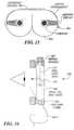
- FIG. 15is a face mask structure with integrated image combining system and computer circuits according to the present invention.
- FIG. 16is a side view of a face mask incorporating an internal optical relay and eyepiece assembly
- FIG. 17is a side view of a further embodiment of a face mask incorporating an internal optical relay and eyepiece assembly
- FIG. 18is a side view of a still further embodiment of a face mask incorporating an internal optical relay and eyepiece assembly
- FIG. 19is a schematic view of an adjustment mechanism
- FIG. 20is a side view of a head set and display assembly of the present invention.
- FIG. 21is a front view of an alternative embodiment of a head set and display assembly
- FIG. 22is a schematic view illustrating a display assembly and microphone
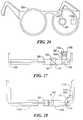
- FIG. 23is a side view of an eyeglass temple according to the present invention.
- FIG. 24is a top view of the eyeglass temple of FIG. 23;
- FIG. 25is a side view of an alternative embodiment of an eyeglass temple according to the present invention.
- FIG. 26is a schematic perspective view of a pair of eyeglasses built according to the present invention.
- FIG. 27is a top plan view, partially cut away, of the eyeglasses of FIG. 26.
- FIG. 28is a plan view of a further embodiment of a pair of eyeglasses according to the present invention.
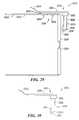
- FIG. 29is a plan view of a display device mounted to a pair of eyeglass frames according the present invention.
- FIG. 30is a plan view of the display device of FIG. 29;
- FIG. 31is a plan view of an imaging assembly and optical element of the display device of FIG. 29;
- FIG. 32is an exploded view of a housing assembly of the display device of FIG. 29;
- FIG. 33is a cross-sectional view of the housing assembly of FIG. 32;
- FIG. 34is a cross-sectional view of the display device of FIG. 29;
- FIG. 35is a cross-sectional view taken along line 6 — 6 of FIG. 34;
- FIG. 36is a plan view of a further embodiment of a display device using a swivel fixture
- FIG. 37is a plan view of the display device of FIG. 36;
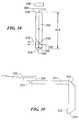
- FIG. 38is a plan view of a further embodiment of an optical element
- FIG. 39is a plan view of a further embodiment of the display device using a graded index lens
- FIG. 40is a plan view of a still further embodiment of the display device illustrating an alternative optical path and optical element
- FIG. 41is a plan view of a further embodiment of the display device using a link element
- FIG. 42is a plan view of the display device of FIG. 41;
- FIG. 43is a side view of a further embodiment of the display device using a mounting along the outer bottom edge of an eyeglass frame;
- FIG. 44is a plan view of a further embodiment having a rotatable adjustment mechanism.
- FIG. 45is a still further embodiment having a reflective liquid crystal display and display illuminator.
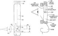
- FIG. 1illustrates a prior art see-through head mounted display system based on lenses and combiners.
- a display 10 and back light 20are mounted with a lens 50 above the user's line of sight. Rays 80 from the display 10 pass through the lens 50 and reflect from the combiner 40 toward the user's eye. Rays 60 from the ambient scene pass through lens 30 and also pass through combiner 40 and are coincident with rays 80 from the display. Thus the user perceives an image comprising the superposition of rays from the display and the ambient scene.
- the lenses in this systemprovide appropriate vergence for the rays so that the image is perceived at the desired depth.
- the size of the various parts in this systemare on the order of 0.5 to 2.0 inches to provide a large exit pupil and require housing and frames that make the system bulky. Additionally, the weight is distributed in such a way as to produce an undesirable torque on the user's head.
- FIG. 2illustrates another prior art head mounted display approach involving a see-around technology.
- a display 10 and backlight 20are mounted with a lens 110 so that rays 100 travel to the eye with appropriate vergence.
- This display systemhaving fewer parts, is somewhat lighter than the see-through display, but it occludes ambient rays. Additionally, both see-around and see-through displays mounted from hats or headbands have a tendency to snag on items in the environment.
- FIG. 3An image source or display 320 and a lens 330 are mounted at the edge of a second “lens” or lens system 300 hereinafter referred to as “main lens” 300 .
- Main lens 300is more specifically in the form of an eyeglass lens (with or without vision-correcting optical power) and an eyepiece assembly shown here as insert 301 , formed for example in the manner of a bifocal insert. It will thus be appreciated that main lens 300 replaces the single lens (or lens system in the case of a bifocal lens) in an eyeglass frame.
- the main lens 300may be more precisely referred to as an optical system comprising embedded lenses and other optical components and surfaces, but is referred to here as main lens 300 for simplicity.
- the term “lens” in general hereinrefers to a surface with optical power and/or to sets of multiple surfaces of optical power, either refractive, diffractive, reflective or otherwise in nature.
- the insert 301 in the main lens 300comprises two materials of different indices of refraction, n 1 and n 2 , with n 1 being greater than n 2 , so that light rays 308 from the image source 320 traveling through the material of higher refractive index and subsequently incident at the interface 302 between the materials are totally internally reflected toward a third lens 340 .
- Ambient light rays 306pass through the interface 302 and are refracted away from the third lens 340 thus improving contrast of the displayed image.
- the two lenses 330 and 340are chosen such that the combined optical power forms a microscope thus allowing the image from the display to be viewed with the desired magnification.
- an air or other fluid filled gapmay be provided between the materials, or the lower index material may comprise air, another fluid or vacuum, so that if fused silica is used for the main lens 300 , the critical angle for total internal reflection will be 43 degrees.
- the angle of the interface 310may be designed for satisfying the condition that the angle of incidence exceed the critical angle for total internal reflection, and also for satisfying the optical requirements for positioning the image to be viewed.
- the optical interface shown hereis planar; however, it may be curved to provide an optical power.
- An alternative embodimentcomprises the use of an insert 301 comprising materials having thin-film interference coatings at the interface to combine the light paths, as is commonly accomplished in dielectric beam splitters and combiners.
- the display 320may comprise a miniature flat panel display, a cathode ray tube or a scanning display as described in U.S. Pat. No. 5,715,337, assigned to the assignee of the present application and incorporated herein by reference.
- the display 320may be responsive to RF video signals with the RF link being analog or digital depending on particular application requirements and available technology.
- FIG. 4illustrates another method of forming the image combining system.
- a cube beam splitter 801 used in reverse as a combinerreplaces the totally reflecting surface described earlier.
- the cube beam splitterfor example Edmund Scientific Part A45,111, has the advantage over the totally internally reflecting surface of introducing practically no refraction of ambient rays; however, the cube beam splitter only passes approximately 50% of the ambient and display light to the eye.
- beam splitter 801comprises a polarizing beam splitter
- display 320provides polarized light (such as from a liquid crystal display or laser-scanned display)
- reflection in the range of 75 to 99%may be obtained, depending on wavelength of the display emission and optical design of the coatings in cube 801 .
- the cubemay also serve as an analyzer for a liquid crystal display, since it efficiently passes one polarization and not the other.
- a housing 820provides a means to hold two glass or plastic plates 810 that are joined to the cube 801 , the plates and other internal parts comprising the main lens 300 .
- Light rays from an image sourceare incident through a hole 821 (see FIG. 6A) in housing 820 .
- Ambient rayspass through one of three paths.
- the first path 830passes through optional polarizing layer 804 , through glass 810 , through cube 801 , through second glass 810 , and then to the eye.
- a second path 831passes through optional polarizing layer 804 , glass 810 , optional polarizing layer 802 , second glass 810 , and then to the eye.
- the purpose of the optional polarizing layersis to make possible an adjustment of the light level of the ambient scene reaching the eye to provide a balancing of the light level between the display and the ambient scenery, which is made possible by mounting optional polarizer 804 on a rotating bezel 803 .
- a third path 832passes through optional polarizing layer 804 , glass 810 , optional polarizing layer 802 , cube 801 , and then through second glass 810 to the eye.
- Light passing along path 832will suffer some distortion owing to the off-axis passage through the cube. This effect can be minimized by shaping the beam splitter in a conical form, and by filling the void 806 with a compound optically matched to the cube 801 .
- the cube beam splitter 801may be designed and oriented to be sensitive to polarization as previously described, and oriented such that when aligned with the polarizing layer 802 , the cube 801 and polarizer 802 absorb equal amounts of rays 830 , 832 , and 831 . If properly aligned, the net transmission of polarized light across the main lens 300 is uniform and the external polarizer 804 may be rotated to adjust the light level of the ambient scene as viewed through the cube or otherwise.
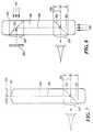
- FIGS. 5A-5E and 6 Aillustrate some of the details of the assembly of an eyeglass frame for the device shown in FIG. 4.
- a triangular block 822receives a pipe 823 which houses the optical path from the display, described further below.
- a mirror 824reflects rays on the light path through an angle of 90°, through the opening 821 to the combiner 801 .
- the block 822may be mounted to the housing 820 in any suitable manner, for example, by screws 825 .
- Two housings 820are assembled to form a pair of eyeglasses, as shown in FIG. 6 A.
- the cube 801 in position 301 , lens 340 and display 320may also be formed within the main lens 300 as a solid casting, which can then be mounted in conventional eyeglass frames 830 , as shown in FIG. 6 B.
- FIG. 7shows another embodiment in which the lenses 330 and 340 are replaced by lenses 360 and 370 respectively, which may be glued to the main lens 300 or which may be formed as part of the main lens 300 if for example the lens is injection molded.
- the main lens 300can be formed as a single solid piece by embedding the optical parts in a solid clear or tinted material, such as an optical cement, polycarbonate, epoxy, polymethyl methacrylate, or glass.
- the moldis provided with surfaces that will yield the desired optical power and/or reflections at various places on or within the main lens 300 .
- the main lens 300may also be formed from a plurality of cast, molded, or machined parts which are then bonded together to form a solid unit, or alternatively which are mounted in the manner shown in FIGS. 4 to 6 .
- a further embodiment of this inventioncomprises the use of an integrated lens 360 with a separate lens 340 or vice versa. Additionally, lenses 330 and 340 , or 360 and 370 , or any combination, may comprise achromatic lenses for color correcting dispersion effects in the optical system, or other lens combinations to reduce image aberrations. It should be recognized that lens 360 is optional and may be eliminated in systems requiring simple magnifying optics.
- FIG. 8Another embodiment of the lens system is shown in FIG. 8 .
- the lens 360 and display 320are moved to a position behind the main lens 300 .
- a reflecting surface 325is provided in the form of a second insert 326 in the main lens 300 for the purpose of directing the incident image to the insert 301 .
- Reflecting surface 325may be of the type implemented in the insert 301 , which itself may comprise cube 802 , or alternatively may be replaced by a mirror mounted internal to the main lens 300 or externally, as shown in FIG. 5 A.
- the insert 301 or insert 326may act as the analyzing polarizer (the analyzer) for the case in which the image source 320 is a liquid crystal display.
- the mirrormay be designed to protect the user's eye in the unlikely event that the display regulating system fails.
- the mirror(at surface 325 ), functioning as an optical fuse, may protect the user from injury by being designed to absorb some of the incident light.
- one or more layers of materials having low thermal conductivitymay be provided beneath the reflective layer of the mirror. With such an arrangement, the light beam may be made to heat the mirror faster than it heats the retina, thereby resulting in damage to the mirror more quickly than to the eye.
- One of the low conductivity layers beneath the mirrormay comprise a material with a high coefficient of thermal expansion which would lead to a bubble or other de-focusing mechanism at the mirror designed to occur at a threshold energy flux below the damage threshold of the retina.
- the image sourcemay also supply infra-red (IR) radiation to enhance this effect.
- IR radiationwould be removed by a filter elsewhere in the system to prevent it from reaching the user's eye.
- the displaymay be back-lit as previously disclosed, or may be illuminated by ambient light rays 401 and/or 402 and/or 403 .
- Such a designcan work with the totally internally reflecting insert 326 , or with a partially or fully reflecting mirror surface 325 , or with a surface with a dielectric coating.
- a fraction of the rays 401 , 402 , and 403will propagate to the display through the combiner 325 . These rays will then be reflected from the display into the optical path leading to the eye.
- the optical systemmay be provided with a condensing or collecting lens to gather and concentrate the rays 401 , 402 , and 403 .
- the rays 401 , 402 , and 403may be supplied by a lamp mounted optically to the main lens 300 for viewing when insufficient ambient light is available.
- insert 326may comprise a polarizing beam splitter which can act as a polarizer and analyzer for the display.
- This embodimentmay be further improved by adding a crossed rotating system of polarizers as is well known in the art to provide an adjustment in the light level of the ambient scenery. In this way, the light from the display and the ambient scenery light level may be balanced.
- the adjustmentmay be made electronically, and a sensor may be employed for automatic compensation or balance between the relative brightness of the images.
- a further improvement to the designs in the foregoing figurescan be made by adding a fourth lens 410 on the front of the main lens 300 over the insert, as shown in FIG. 9 .
- the lens 410being generally of a negative power, counters the positive optical power of the lens 370 so that rays 306 from the ambient scene can be viewed without significant magnification, while rays from the display, which do not pass through lens 410 , are viewed with magnification.
- the lens 410may have positive or negative optical power depending on the specific vision correction requirements of the user. Alternatively, the optical power of lens 410 may be chosen to provide magnification in the manner of a jeweler's loop.
- lens surfacesmay be added on either side of the main lens 300 to correct the vision of the user, in the manner of ordinary eyeglasses, and any of the microscope lenses may be adjusted in optical power to correct the user's vision.
- Other lensesmay be added to further correct the vision through lenses 370 and 410 . Note also that these lenses may also be incorporated substantially within the volume of the main lens 300 .
- the index of refraction n and the radius of curvature of the lensesmust be corrected from their values in air to obtain the desired optical power, within the potting, molding, or machined medium.
- the indices of refraction of the compounds and the lens materialmay be chosen from many compounds having indices in the range of 1.4 to 1.6 for optical polymers or glass, and 1.5 to 2.0 for various other optical materials.
- the optical powermay be developed by providing an air gap or vacuum within the molding material or by materials of low refractive index, with the radius of curvature appropriately designed. Another approach is to fill such a gap with a liquid of high or low refractive index. A further alternative is to employ diffractive or holographic lens elements within the main lens 300 .
- FIG. 10shows another embodiment in which several field lenses 901 , 902 are provided within the main lens 300 .
- Such field lenseshave the beneficial effect of distributing the optical power, thus reducing the need for high optical power at the eye lens.
- Such lensesalso can serve to increase the field of view.
- These lenses and the other optical partsmay be formed, for example, by the injection molding or machining of multiple parts, followed by coating of the interior surfaces with metal or dielectric layers, and followed further by the assembly of the parts to form the main lens 300 with embedded optical surfaces. Additionally, if the optical power of lenses 901 and 902 is sufficient, lenses 370 and 410 are not needed.
- main lens 300in order to form a main lens 300 well-suited for incorporation in an eyeglass frame, it is desirable to maintain the thickness 934 of the main lens 300 within the range of conventional eyewear (less than 25 mm and preferably in the range of 1 mm to 15 mm).
- the surfaces of main lens 300form an aperture stop in the internal optical path which is of a dimension equal to the thickness 934 .
- the partially reflective interface 324also forms a stop. Depending on the magnification of the lenses, these stops may restrict the field of view of the image from the display. This invention overcomes some of the limitations of these stops by using field lenses 901 , 902 .
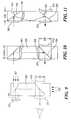
- FIG. 11A second method of overcoming the stop introduced by the main lens 300 thickness 934 is shown in FIG. 11 .
- the interfaces 324 , 325are set at angles 455 and 456 less than 45° so that the thickness 934 of the main lens 300 may be reduced.
- the optical pathrequires one or more reflections from the interior surfaces of main lens 300 , which occur by total internal reflection as previously discussed. In such a case, embedded lenses 901 are canted appropriately, as shown in the figure.
- FIG. 12illustrates how the main lens 300 can be formed using a concave mirror in the eyepiece.
- Linearly polarized light from a display 978such as a liquid crystal display, and back light 977 , enters the main lens through optional lens 979 , and reflects from mirror 980 .
- the lighttravels between the surfaces of main lens 300 to a polarizing beam splitter coating 981 which passes linearly polarized light of one polarization, and which reflects linearly polarized light of the orthogonal polarization.
- the polarization of the display and beam splitter surfacesare arranged so that the light from the display is passed by the beam splitter 981 through a quarter wave plate 982 to a concave mirror 983 .
- the optical power of the concave mirrormodifies the vergence of the light from the display so that the image is magnified and placed at a conveniently distance for viewing.
- the lightis reflected by mirror 983 and travels back through the quarter wave plate 982 .
- the quarter wave plateis oriented so that the polarization of the light, which has passed twice through the plate, is rotated into the orientation which is reflected by coating 981 .
- the viewersees a virtual image in front of the glasses at a distance determined by the optical powers of the mirror 983 and 979 , and the distances between the optical surfaces, by methods well-known in the imaging optics art.
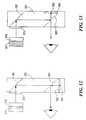
- the mirror 983 and quarter wave plate 982may be placed relative to the optical path as shown in FIG. 13 .
- the mirror 982must be partially silvered to permit the passage of ambient light to the viewer's eye.
- the method shown in FIG. 11, in which total internal reflection is used to change the angle of incidence upon the beam splitter coating,may be used with the approach shown in FIGS. 12 and 13 to increase the field of view.
- lens 410(FIG. 9) may be changed to an opaque disc to convert the see-through system to a see-around system.
- the insert 301may be increased in extent to a large field of view, and the front surface of the main lens 300 may be provided with an opaque cover to form a full immersion system. Any of the opaque covers may be replaced by a liquid crystal shutter that can be electronically adjusted to reduce the light level of the ambient scenery or to block it out entirely. Photochromic materials may also be applied to control ambient light.
- a mirror or a prism with a totally internally reflecting hypotenuse as previously describedmay be used to form the insert 301 .
- Such a deviceis no longer a combiner, but rather is a simple reflector which is all that is needed in a see-around system. This has an advantage over other reflector systems, because the reflecting surface is provided within the main lens 300 and therefore has safety and durability advantages over other approaches.
- a further manner of forming the image combineruses binary optics to form a diffractive optical element having a binary surface structure formed in a surface characterized in the simplest case by an angle 310 (FIG. 3) with respect to the base of the main lens 300 .
- the advantage of a diffractive optical elementis that the angle 310 may be made large while still directing light through lens 340 , whereas at a reflective surface the angles are fixed by the law of reflection. This permits the field of view through lens 340 to be large, while also permitting the thickness of the main lens 300 to remain relatively small.
- Lens 340 and other lensesmay also comprise diffractive optical elements.
- a disadvantagemay be undesirable wavelength-dependent effects that could be present in a color system.
- the flexibility inherent in the optical design of the complete system described above, such as the ease of insertion of counterbalancing diffractive optical elements elsewhere in the optical pathmakes possible the compensation for chromatic effects, if any.
- the lenses described in the various embodimentsmay be selected to form an achromatic optical relay to remove chromatic aberrations inherent in the various parts of the lens system. It may also be seen that features of the various embodiments may be combined. Additionally, although the figures show singlet lenses, any of the lenses may be replaced by combinations of multiple lenses or surfaces designed to reduce distortion, improve field flatness or add other improvements to the resultant image seen by the user.
- the main lensmay be fashioned in a wide variety of shapes, as shown in FIG. 14 .
- the cross sectionshows one possible internal optical design in which the light is relayed to the eyepiece by a mirror 325 .
- the eyepiececomprises a polarizing beam combiner 920 , quarter wave plate 930 and concave mirror 900 .
- the internal optical pathmay be the same for each of the shapes shown, which are formed using standard edge grinding techniques.
- the shape of the main lensmay even be simply the rectangular section comprising the optical path.
- the lenses of these various shapesmay be held in a standard eyeglass frame, or an unconventional stylized frame resembling an eyeglass frame, or by any other head-mounted structure including booms, eyeglass clip-on devices or other appliances.
- FIG. 15shows an example of the integration of the optical system 870 , a face mask structure 872 , and computer circuits 874 to form a completely integrated computer within a face mask system. This is possible in systems in which the face mask provides sufficient area at the edge for integrated circuit mounting. As the size of integrated circuits decreases, it will become possible to mount displays and circuits in this way on eyeglasses.
- the displaycan be mounted directly to the edge of the lens, as indicated in FIG. 15 .
- circuitry and displayscan also be potted within the face mask at its edge to yield hermetic protection from water.
- FIG. 15shows two displays, which allow generation of a stereo image.
- the combinerscan be located directly within the ordinary field of view (as shown) or can be located out of the ordinary field of view such that, to see the display, the user must look up, down, or to the side, to wherever the optical system has been placed.
- Suitable displays for a face maskare active matrix electroluminescent displays or active matrix liquid crystal displays, which are commercially available.
- FIG. 16illustrates a face mask 510 or goggles having a display assembly including an internal optical relay 512 and eyepiece 514 embedded within a solid face mask visor 516 .
- the visoris held in position by a rubberized housing or face mask frame 518 as is commonly provided in SCUBA masks, ski masks, and other face mask systems.
- the visortypically has a thickness of between 4 mm and 12 mm.
- the display assemblyincludes a display which may be mounted directly against the visor or may be placed in a housing 520 so that the display is in optical communication with the optical relay in the housing.
- FIG. 17shows an alternative embodiment in which the display assembly is provided in the face mask, for example, behind an exterior visor 516 ′.
- the optical relay 512 ′protrudes through an opening 522 in the face mask frame 518 .
- the openingmay be at the top of the frame above the eye, as shown, or in some other location.
- the use of a clear optical relayminimizes interference with vision.
- the optical relaymay be slidable within the housing to provide a vertical adjustment.
- the display housing and cablesmay be shaped to conform to the shape of the face mask frame.
- the optical relay and eye pieceextend in the cavity behind an exterior face mask visor.
- This exterior visormay include an ultraviolet filter or other sun filter or shade, ballistic protective shield, chemical shield, or other visor intended to protect the face.
- the optical coatings on the exterior shielddo not interfere with the visibility of the eyepiece.
- the optical deviceis protected by the exterior visor.
- the devicemay be positioned in front of the exterior shield.
- the devicemay be remountably clipped to the face mask frame, which may be useful for quick attachment and detachment of the display device.
- a further alternativeis the use of both an exterior visor 516 ′ and interior visor 516 ′′, illustrated in FIG. 18 .
- the optical relaymay be located in a cavity or space 524 between the exterior and interior visors.
- the interior visorcan be used to provide a greater degree of ballistic or other protection and may also protect the face from contact with the optical relay in the event of an accidental compression of the face mask against the face.
- FIG. 19illustrates a detail of one possible adjustment mechanism for the display shown in FIG. 17 .
- the optical relayextends through a ball and socket joint 526 mounted within the face mask frame 518 .
- the optical relay 514 ′can slide back and forth to provide a translational adjustment of the position of the eyepiece. Additionally, the ball can rotate in the socket to provide a range of angular adjustments of position of the eyepiece 514 ′.
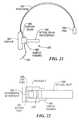
- a display device on a head-born audio set 530(an audio head-set) is shown in FIG. 20 .
- the head-setincludes a frame 532 , a head pad 534 for wearing over the user's head, and an ear cup 536 which fits over the user's ear.
- a boom 538is attached to the frame of the device in the manner of a mic boom to extend near the user's mouth.
- the display housing 540is mounted on a display boom 542 which is attached to the frame so that the optical relay and eyepiece are positioned in front of the eye.
- the display boommay be attached to the frame in any suitable manner, such as with a bolt and nut to provide an adjustable clamping mechanism 544 .
- FIG. 21shows an alternative embodiment in which the display assembly 552 is attached to a head band 554 , such as head bands which are customarily used for light weight audio head transducers.
- This type of head bandmay include transducers mounted in one or two ear cups 556 .
- a pad 558may be provided at the other end of the head band.
- a boom 560is attached to the head band 554 to support the display in a housing 560 , optical relay and eyepiece 562 , and cable 564 .
- the boommay be remountably attached to the head band if desired.
- the head bandmay include no transducers, in which case a simple pad is mounted at each end of the head band.
- the display housingmay also include a miniature microphone 566 customarily used in hearing aids, as shown in FIG. 22 .
- the microphonemay comprise a differential noise cancelling design or phased array positioned to preferentially collect audio signals from the direction of the user's mouth.
- FIG. 22shows a differential microphone in acoustic communication with the environment through top and bottom acoustic ports 568 , 570 . Sound enters the two ports and is acoustically subtracted at the microphone so that only the difference in acoustic signals is converted to an electrical signal.
- the microphoneselects sounds from the area of the user's mouth, which enter the lower acoustic port in greater magnitude than the top port, whereas other environmental sounds enter the ports in approximately equal magnitude.
- the portscan be configured mechanically to provide the greatest possible acoustic selectivity for the user's voice.
- the display housing 560can incorporate a noise cancelling microphone design.
- the microphoneis in electrical communication with audio circuits in the computer or other device through wires in the cabling. In this way, the system may obviate the need for a separate microphone.
- FIGS. 23 and 24show a temple design for remountable attachment to eyeglasses.
- the temple 574is provided with a series of drilled and tapped holes 576 which provide a mounting surface for remountable displays, cameras, audio or other hardware.
- the templemay comprise metal stock with a square cross section having a cross sectional length in the range of 2 mm to 6 mm. Alternatively, to reduce the weight of such a system, the cross section may be minimal (nominally 1 mm) except at the locations of the attachment holes 578 , as shown in FIG. 25 .
- FIGS. 26 and 27Eyeglasses displays built in accordance with the invention described herein are illustrated in FIGS. 26 and 27.
- the main lens 300is housed in a commercial eyeglass frame 830 .
- the main lens 300comprises an embedded polarizing beam splitting cube 801 and an embedded prism 1100 which serve to reflect light from the active matrix liquid crystal display 320 .
- the displayis lit by backlight 1103 and the display and light are contained in housing 1105 .
- the displayis connected electrically to electronic circuits (not shown in FIGS. 26 or 27 ).
- the display 320is mounted optically to spacer 1101 so that the index of refraction of the medium between the display and the surface of lens 370 is relatively well-matched to minimize internal reflections, the indices of refraction of the materials being in the range of 1.4 to 1.6.
- the display 320is positioned so that the polarization of light emitted by the display is in a favorable direction for reflection by cube 801 toward the eye, with minimal transmission through the cube's interface.
- Lens 370a singlet plano-convex lens having a positive power, reduces the vergence of rays from the cube 801 , thus enabling the user to perceive a virtual image at approximately 50 cm.
- Lens 410a singlet plano-concave lens having a negative power, pre-corrects light from the ambient scene so that in combination lenses 370 and 410 transmit light relatively free of vergence change.
- the optimized selection of the relative power and spacing of lenses 410 and 370 , and/or the use of multiple lenses (doublets for example) as provided for in this invention,will yield reduced overall distortion of the ambient image as seen through the cube.
- the overall thickness of the main lens 300 ( 934 in FIG. 10) in this embodimentis 6.25 mm.
- FIG. 28illustrates a method of packaging a flat backlight 1110 , display 320 and prism 1111 within the temple 1112 of eyeglasses to conceal the display.
- the mirror 983 and plate 982can be embedded within the main lens 300 as shown in FIG. 28 or as previously described herein. Prescriptive correction may be obtained by bonding lenses 1200 to the front surfaces, as shown in FIG. 28, or to the inside surface.
- prescriptive correction curvaturemay be formed integrally to main lens 300 .
- the lenses 1200may be concave or convey. Sensors and lenses (i.e. a camera system) can be added, as can an eyetracking system, both of which have been previously described herein.
- the appearance of the main lens 300is similar to a bifocal lens.
- FIG. 28shows a monocular system; however, two main lenses 300 , left and right, may be employed for a binocular system.
- the left main lens 300may house the display system, while the right main lens 300 may house a sensor system.
- the presence of embedded opticscan be further disguised by using polarizing, photochromic, tinted, or reflective films in the manner of sunglasses. The result is an eyeglasses display system having the aesthetic appeal of conventional eyewear, with no display, camera, or eyetracker evident upon casual inspection.
- FIG. 29A display device mountable to an eyeglass frame is illustrated generally in FIG. 29 .
- the display device 2010comprises an imaging assembly 2012 (see FIGS. 32 - 34 ), an optical element 2014 , and a housing assembly 2016 which is removably mountable to eyeglass frames 2018 .
- the housing assembly 16includes an enclosure 2020 for containing circuitry 2022 for receiving data or images relayed to the display device 2010 and for containing the imaging assembly.
- the circuitrymay include integrated or discrete circuits which are connected to the imaging assembly.
- Light from the imaging assemblyis relayed via the optical element 2014 through the eyeglass lens 2024 to the user's eye.
- the optical element 14comprises a transparent fixture or relay 2026 and an eyepiece assembly 2028 which, in the embodiment shown in FIGS. 29 through 31, comprises a mirror 2030 and lens 2032 .
- the housing assembly 2016is mounted to the temple 2034 of the user's glasses 2018 by a clamping assembly 2036 illustrated by a mounting fixture 2038 and clamps 2040 .
- the relay 2026 and eyepiece assembly 2028are positioned in front of the user's eyeglass lens 2024 so that the image is viewed through the eye lens 2032 which is positioned by the user in a convenient location for viewing.
- the housing assemblyis located substantially outside the user's field of view, which means that the housing assembly does not block the user's main field of view.
- the main field of viewis defined by the view through the lens.
- the main field of viewis defined by the area bounded by about 45° to the sides of a line looking ahead and about 20° above and below the line the looking ahead.
- the imaging assembly 2012may comprise a transmissive or reflective miniature active matrix liquid crystal display (AMLCD), an electroluminescent display, or any other miniature flat panel display having a screen diagonal of less than 2 cm.
- AMLCDtransmissive or reflective miniature active matrix liquid crystal display
- electroluminescent displayor any other miniature flat panel display having a screen diagonal of less than 2 cm.
- the Kopin Cyber Display P/N KCD-QMO2-AAis suitable.
- the imaging componentmay comprise a scanning display as described in U.S. Pat. No. 5,715,337 or any number of other imaging elements formed from liquid crystals, light emitting diodes, electroluminescent materials or field emissions displays.
- FIGS. 32 through 34an AMLCD image generator 2040 with a backlight 2042 is shown.
- the backlightmay be made from any number of illuminators such as light emitting diodes, incandescent lamps, lasers, or other light emitting devices.
- the backlightis repositioned as a front light by methods known in the art
- the optical element 14preferably comprises five optical surfaces 2044 , 2046 , 2048 , 2049 , and 2050 (FIG. 34 ).
- the optical element 2014is preferably rectangular in cross section, as shown in FIG. 35 .
- the surfaces 2052 and 2053may optionally also be of optical quality, or may be frosted or blackened, and may or may not be optically parallel.
- sections of the optical relay 2026 within the user's main field of vieware optically clear and of uniform index of refraction.
- the surfaces 2049 and 2050are polished and optically parallel so that ray 2054 representing a ray from the ambient scene traverses the relay with little or no change in propagation angle.
- Surface 2044which may optionally be formed by a lens 2045 , receives rays created by the imaging assembly.
- the rayspropagate through the relay 2026 to the surface 2046 , which comprises a mirror 2030 in the embodiment illustrated in FIGS. 30 through 36.
- the sides of the relay 2026are preferably parallel to minimize refraction and thus displacement in the image.
- the mirror 2030reflects the light toward the surface 2048 of the lens 2032 .
- the lens 2032modifies the vergence of the rays from the imaging assembly 2012 so that the image can be viewed with magnification and with the image formed at a comfortable distance between about 25 cm and infinity, depending on lens positions and focal lengths.
- the typical focal lengths of the lenses 2045 and 2032are in the range of 20 to 100 mm.
- the lens surfaces 2044 and 2048modify the vergence of the light from the imaging assembly to create a virtual image in front of the user at a distance of between 25 cm (close) and infinity.
- the distance of the virtual imagemay be set by selection of the focal length of the lens surfaces 2044 and 2048 and by adjustment of the distances between the lens surfaces 2044 and 2048 and the imaging assembly.
- Other folds using mirrorsmay be added to the optical path to relay the light on other optical paths if desired, or the light may be relayed by total internal reflections occurring along the sides of the relay 2026 .
- FIGS. 29-31illustrate in particular a “see-around” embodiment of the invention.
- the relay 2026serves both as a mechanism for transmitting the image to the eyepiece assembly, and also as a structural member for supporting the eyepiece assembly in the user's field of view. Since the relay 2026 is transparent, the occlusion of the user's visual field is minimal or for certain see-through designs (for example FIG. 38 ), zero, and the obscuration of the user's face is minimal.
- a covercould be placed over or formed within the optical element to block ambient light from passing through the optical element if desired, for example, to reduce glint or other undesirable reflections.
- the optical element 2014can be swung out of the user's visual field when not in use, so that the obscuration can conveniently be eliminated.
- the inventionthereby provides a miniature, clear, optical element 2014 so that the user's vision is not significantly impeded by the presence of the display.
- the present inventioncan be made very small, because the imaging assembly is located at the side of the user's eyeglasses, thereby minimizing the amount of structure in front of the user's eye.
- the housing assembly 2016comprises a body 2060 , preferably having an open side 2062 which is covered by one or more coverplates. In the embodiment shown, two coverplates 2064 , 2066 are used.
- the components to receive the data and/or drive the displayare mounted within a cavity 2068 in the body.
- Data or imagesmay be relayed to the device by a cable 2070 which enters the body 2060 through an aperture 2072 at one end thereof.
- the cablemay comprise wire, one or more optical fibers as described in U.S. Pat. No. 5,715,337, or a fiber optic coherent bundle image conduit.
- the data or imagesmay be relayed to the device by radio frequency (RF) transmission.
- RFradio frequency
- the coverplates 2064 and 2066are affixed to the body 2066 in any known manner, such as with screws or adhesive, after insertion of the components.
- the componentsinclude a flexible circuit 2074 made of Kapton or other material known in the art, upon which is provided metal conductors or traces which connect the various components, such as terminating resistors 2076 , 2078 to input cable 2070 .
- the flexible circuitalso connects the cable to one or more LEDs that form the backlight 2042 , and the second flexible circuit 2080 that connects the system to the display 2040 .
- the displayis visible through an opening 2082 in the coverplate.
- the optical element 2014may be affixed to the coverplate 2066 at a collar 2084 .
- the collarmay be affixed to the coverplate in any known manner or may be formed integrally with the coverplate, such as by molding.
- the optical element 2014may be held in place by friction so that adjustments in focus may be made by the user, simply by moving the optical element 2014 with respect to the imaging assembly, by sliding the optical element within the collar 2084 .
- a friction lockmay be added to lock the optical element in a desired position relative to the imaging assembly, as would be known by those of skill in the art.
- the optical elementmay be fixed in place by adhesive, screws, or any other manner known in the art.
- the position of the optical element 2014 in the collaris adjusted during assembly to provide the required distance between the optical surfaces of the optical element and the imaging assembly.
- this distanceis 10 to 15 mm, but it can be zero if the cavity between the imaging assembly and the entrance surface 2044 of the optical element 2014 is filled with index of refraction-matched epoxy.
- the clamping assembly 2036may be affixed to the housing assembly in any suitable manner.
- the mounting fixture 2038may be adhesively or otherwise fastened to the coverplate 2064 .
- the clamps 2040may be configured to allow the display device to be positioned at a variety of elevations with respect to the temple.
- the body 2060may be attached to the mounting fixture 2038 by a rotary joint formed by discs 2650 and 2660 , as illustrated in FIG. 44 . These discs rotate with respect to each other about a central pivot point and may have click stops built within to hold the device at various predefined angles with respect to the eyeglass temples, as would be known by those of skill in the art.
- the optical element 2014may be mounted on a swivel fixture 2090 as shown in FIGS. 36 through 37.
- the swivel fixture 2090pivots around a pin 2092 so that the device can fold up in a compact form for storage or convenience while remaining attached to the eyeglasses.
- the eyepiece assembly 2128comprises a polarization beam-splitter coating 2129 , quarterwave plate 2131 , and focusing mirror 2130 .
- Polarized light from the displayis passed by the beam-splitter coating 2129 , through the quarterwave plate 2131 , to the focusing mirror 2130 .
- the reflected lightpasses again through the quarterwave plate 2131 , and the light, having passed twice through the properly oriented quarterwave plate, has a polarization which is rotated in a direction orthogonal to the original polarization, and the light is therefore reflected by the coating 2129 to the eye, as shown by light ray 2135 .
- Light having polarization oriented properly with respect to the beam splitter 2129 from the ambient beyond the device, represented by light ray 2137passes through the eyepiece.
- FIG. 39Yet another embodiment is shown in FIG. 39 .
- the imageis relayed from an image assembly in the housing 2226 to the eye lens 2232 by an image relay comprising a graded index lens 2211 and mirrors 2215 and 2228 .
- the relaymay comprise a coherent fiber bundle or conventional lens relay.
- Such image relaysmay be formed from polished glass to reduce the obscuration and to improve peripheral vision.
- This embodimentfurther removes obscuring surfaces from the user's face.
- the devicefunctions in the following way.
- the imageis provided by a display as previously described.
- the imageis placed at the focal plane of the relay 2211 .
- For the graded index relaythis is accomplished through a reflection at mirror 2213 , so that the object image is at the entrance pupil of the relay system.
- the relayforms an image at its distal end which is relayed to the eyepiece assembly 2228 by a mirror 2215 .
- FIG. 40illustrates another embodiment of the remountable display device.
- the lightis relayed from an imaging assembly in the housing 2366 along an optical conduit 2313 to a reflective surface 2315 .
- the reflective surfacemay comprise a polished glass surface, in which the reflection occurs by total internal reflection, or it may comprise a metal or other coating intended to reflect the rays from the imaging assembly within the display housing toward the eyepiece assembly 2319 along the light path 2317 . Any number of folds of this type may be incorporated to cause the eyepiece and housing assembly to be placed in convenient, ergonomic, or aesthetic locations.
- the housing assemblymay be fixed to the frame 2318 in a position in which it is easy to attach or detach the device.
- Ergonomic considerationsinclude obtaining a degree of balance in the device which can be the result of placing the housing and part of the optical conduit over the frame so that the device's center of gravity resides over the frame.
- Aesthetic considerationsinclude minimizing the amount of surface area of the device around the user's face.
- FIGS. 41 and 42illustrate a further embodiment of the display device with a link element 2411 that connects the imaging assembly and optical element 2414 to the housing assembly 2416 .
- the housing assemblyincludes a main body 2460 which contains the connections for the cable and the flexible circuits as well as electronic components.
- a further body 2466supports the imaging assembly.
- the link element 2411connects the main body 2460 and the further body 2466 and provides a support for wires connecting the components in the main body with the imaging assembly.
- the link elementallows the optical element to be folded out of view, as shown in FIG. 12, without adjusting the mounting mechanism that attaches the housing to the temple of the user's eyeglasses.
- the link elementalso allows some adjustment of the position of the optical element in front of the eyeglass lens.
- FIG. 43illustrates a method of remountably attaching the device to the eyeglass frame front 2700 .
- a clamping apparatus 2701 hinged at point 2710 and drawn together by spring 2703is affixed to the bottom of the frame front below the lens.
- the clampmay be shaped in a manner similar to the curvature of the frame to provide increased contact area between the clamp and the frame front.
- Small handles 2720are provided to apply force against the spring 2703 to release the clamp.
- Affixed to the clamp 2701is the housing 2090 of the display device that has been previously described.
- the optical relay 2026extends into the user's main field of view to provide an image. Any of the foregoing adjustments and pivots may be implemented in order to position the image at a location convenient for viewing.
- This inventionmay be used with a reflective liquid crystal display, as shown in FIG. 45.
- a compact illuminatoris formed from a polarization beam splitter cube 3105 or other polarization splitting optical element.
- LEDs 3140 or another illumination sourceprovides light, represented for simplicity by single ray 3141 , to the display by reflection from beam splitter interface 3106 .
- This interfacereflects one linear polarization and transmits the other, represented for simplicity by ray 3142 , to a black surface 3107 .
- the black surfaceabsorbs the transmitted light.
- the reflected lightfurther reflects from display 3100 which rotates the polarization of the bright pixels so that the interface 3106 acts as an analyzer in a manner well known in the art. Films may be used to improve the uniformity of the image.
- Film 3120may comprise for example a linear polarizer designed to pre-absorb the undesired polarization to reduce reflections and improve contrast.
- Film 3110may comprise a diffuser to improve the uniformity of the illumination.
- the display and illumination systemproduce an image which is viewed along the optical axis represented by ray 3200 . While FIG. 45 shows the illuminator placed near the display, it may also be combined with various components of the viewing optics and may be placed in alternative locations.
- the inventionalso includes methods for viewing a display with high magnification and high resolution. For cases in which the display is small and the degree of magnification large, additional optical surfaces may be introduced to magnify the image and reduce or eliminate distortions, by techniques that are well known in the art.
- This inventionincludes any number of lenses, mirrors, stops, and other optical surfaces arranged to provide magnification, focus adjustment, aberration control, and other features consistent with the foregoing specifications.
- Alternative embodimentsinclude various forms of eyepiece, illumination optics, and mounting fixtures.
- Two display devices operated in cooperation, one device in front of each of the two lenses of a pair of eyeglasses,can also be used if desired to provide a binocular display.
- the componentsmay be formed from a variety of suitable materials.
- the optical relaymay be formed from glass or a plastic material such as polycarbonate resin, allyl diglycol carbonate monomer, polymethyl methacrylate, or epoxy resin.
Landscapes
- Physics & Mathematics (AREA)
- General Physics & Mathematics (AREA)
- Optics & Photonics (AREA)
- Health & Medical Sciences (AREA)
- Ophthalmology & Optometry (AREA)
- General Health & Medical Sciences (AREA)
- Acoustics & Sound (AREA)
- Otolaryngology (AREA)
- Spectroscopy & Molecular Physics (AREA)
- Engineering & Computer Science (AREA)
- Manufacturing & Machinery (AREA)
- Devices For Indicating Variable Information By Combining Individual Elements (AREA)
- Liquid Crystal (AREA)
Abstract
Description
Claims (14)
Priority Applications (1)
| Application Number | Priority Date | Filing Date | Title |
|---|---|---|---|
| US09/653,751US6384982B1 (en) | 1996-10-08 | 2000-09-01 | Compact image display system for eyeglasses or other head-borne frames |
Applications Claiming Priority (6)
| Application Number | Priority Date | Filing Date | Title |
|---|---|---|---|
| US2799896P | 1996-10-08 | 1996-10-08 | |
| US08/844,098US5886822A (en) | 1996-10-08 | 1997-04-18 | Image combining system for eyeglasses and face masks |
| US6443097P | 1997-10-30 | 1997-10-30 | |
| US09/170,887US6023372A (en) | 1997-10-30 | 1998-10-14 | Light weight, compact remountable electronic display device for eyeglasses or other head-borne eyewear frames |
| US09/271,597US6204974B1 (en) | 1996-10-08 | 1999-03-17 | Compact image display system for eyeglasses or other head-borne frames |
| US09/653,751US6384982B1 (en) | 1996-10-08 | 2000-09-01 | Compact image display system for eyeglasses or other head-borne frames |
Related Parent Applications (1)
| Application Number | Title | Priority Date | Filing Date |
|---|---|---|---|
| US09/271,597DivisionUS6204974B1 (en) | 1996-10-08 | 1999-03-17 | Compact image display system for eyeglasses or other head-borne frames |
Publications (1)
| Publication Number | Publication Date |
|---|---|
| US6384982B1true US6384982B1 (en) | 2002-05-07 |
Family
ID=23036259
Family Applications (3)
| Application Number | Title | Priority Date | Filing Date |
|---|---|---|---|
| US09/271,597Expired - LifetimeUS6204974B1 (en) | 1996-10-08 | 1999-03-17 | Compact image display system for eyeglasses or other head-borne frames |
| US09/652,629Expired - LifetimeUS6356392B1 (en) | 1996-10-08 | 2000-08-31 | Compact image display system for eyeglasses or other head-borne frames |
| US09/653,751Expired - LifetimeUS6384982B1 (en) | 1996-10-08 | 2000-09-01 | Compact image display system for eyeglasses or other head-borne frames |
Family Applications Before (2)
| Application Number | Title | Priority Date | Filing Date |
|---|---|---|---|
| US09/271,597Expired - LifetimeUS6204974B1 (en) | 1996-10-08 | 1999-03-17 | Compact image display system for eyeglasses or other head-borne frames |
| US09/652,629Expired - LifetimeUS6356392B1 (en) | 1996-10-08 | 2000-08-31 | Compact image display system for eyeglasses or other head-borne frames |
Country Status (4)
| Country | Link |
|---|---|
| US (3) | US6204974B1 (en) |
| EP (1) | EP1169663A4 (en) |
| JP (1) | JP2002539498A (en) |
| WO (1) | WO2000055676A1 (en) |
Cited By (312)
| Publication number | Priority date | Publication date | Assignee | Title |
|---|---|---|---|---|
| US20020176173A1 (en)* | 2001-04-30 | 2002-11-28 | Song Young-Ran | Wearable display system and process thereof |
| US20030068057A1 (en)* | 2001-10-06 | 2003-04-10 | Miller Eric C. | Information system using eyewear for communication |
| US20030090439A1 (en)* | 2001-09-07 | 2003-05-15 | Spitzer Mark B. | Light weight, compact, remountable face-supported electronic display |
| US20030218718A1 (en)* | 2002-01-11 | 2003-11-27 | Renaud Moliton | Ophthalmic lens having a projection insert |
| US6680802B1 (en)* | 1999-08-05 | 2004-01-20 | Olympus Optical Co., Ltd. | Head-mounted image video display |
| US20040108981A1 (en)* | 2002-12-10 | 2004-06-10 | Atika El Sayed | Novel mobile audio visual system for managing the information |
| US20040156114A1 (en)* | 2003-01-03 | 2004-08-12 | Sayed Atika El | Facial mounting equipped with a lateral device for diffusion of virtual images towards a user's pupil |
| US20040156012A1 (en)* | 2002-07-26 | 2004-08-12 | James Jannard | Electronic eyewear with hands-free operation |
| US20040160573A1 (en)* | 2000-06-02 | 2004-08-19 | James Jannard | Wireless interactive headset |
| US20040174608A1 (en)* | 2003-03-05 | 2004-09-09 | 3M Innovative Properties Company | Diffractive lens optical design |
| US20040178970A1 (en)* | 2002-12-10 | 2004-09-16 | Ingineo Sas | Face-mounted apparatus having spectacles and a video display integrated into the spectacles |
| US20040212776A1 (en)* | 2003-04-25 | 2004-10-28 | Spitzer Mark B. | Binocular viewing system |
| US20050007667A1 (en)* | 2003-07-10 | 2005-01-13 | Fergason John D. | Light sensor arrangement for auto-darkening lenses and method |
| US20050180687A1 (en)* | 2002-03-21 | 2005-08-18 | Yaakov Amitai | Light guide optical device |
| US20050201585A1 (en)* | 2000-06-02 | 2005-09-15 | James Jannard | Wireless interactive headset |
| US20050237271A1 (en)* | 2002-08-12 | 2005-10-27 | Scalar Corporation | Image display device |
| FR2872587A1 (en)* | 2004-07-02 | 2006-01-06 | Essilor Int | OPHTHALMIC DISPLAY HAVING A DEVICE FOR ADJUSTING THE USER'S PUPILLARY DISTANCE |
| FR2873212A1 (en)* | 2004-07-16 | 2006-01-20 | Essilor Int | OPTHALMIC LENS FOR REALIZING AN OPTICAL DISPLAY |
| US20060023160A1 (en)* | 2004-08-02 | 2006-02-02 | Cartier Jon P | Lens structure and method of making the same |
| US20060055786A1 (en)* | 2004-03-09 | 2006-03-16 | Viosport | Portable camera and wiring harness |
| EP1643401A1 (en)* | 2004-10-01 | 2006-04-05 | General Electric Company | Method and apparatus for surgical operating room information display gaze detection and user prioritization for control |
| US20060072067A1 (en)* | 2000-06-02 | 2006-04-06 | Jannard James H | Eyeglass with MP3 player |
| WO2006048564A1 (en)* | 2004-11-05 | 2006-05-11 | Essilor International, Cie Generale D'optique | Ophthalmic display comprising an ophthalmic lens and an optical image |
| USD523005S1 (en) | 2003-12-31 | 2006-06-13 | Eyeneo Sas | Video display control unit comprising charging base and control unit box |
| US20060192307A1 (en)* | 2005-02-25 | 2006-08-31 | Eugene Giller | Method for producing high quality optical parts by casting |
| US20060192306A1 (en)* | 2005-02-25 | 2006-08-31 | The Microoptical Corporation | Manufacturing methods for embedded optical system |
| US20060238877A1 (en)* | 2003-05-12 | 2006-10-26 | Elbit Systems Ltd. Advanced Technology Center | Method and system for improving audiovisual communication |
| US20070047091A1 (en)* | 2005-03-22 | 2007-03-01 | The Microoptical Corporaiton | Optical system using total internal reflection images |
| US20070064888A1 (en)* | 2005-09-14 | 2007-03-22 | Pat Nola | Method and system for call initiation in a video relay service |
| US20070064894A1 (en)* | 2005-09-14 | 2007-03-22 | Armstrong Edward F | Method, system and device for relay call transfer service |
| US20070064097A1 (en)* | 2005-09-14 | 2007-03-22 | Cupal Matthew D | Method and system for auto configuration in a video phone system |
| US20070081646A1 (en)* | 2005-09-23 | 2007-04-12 | Cupal Matthew D | Method and system for visual spatial caller identification |
| US20070097513A1 (en)* | 2003-09-10 | 2007-05-03 | Yaakov Amitai | Substrate-guided optical devices |
| USD547346S1 (en) | 2004-03-09 | 2007-07-24 | V.I.O., Inc. | Camera |
| US20070184881A1 (en)* | 2006-02-06 | 2007-08-09 | James Wahl | Headset terminal with speech functionality |
| WO2007110551A1 (en)* | 2006-03-28 | 2007-10-04 | Panagiotis Pavlopoulos | System for hearing-impaired people |
| JP2007537610A (en)* | 2004-05-11 | 2007-12-20 | エルビット・システムズ・リミテッド | Audiovisual communication improvement method and system |
| USD558761S1 (en) | 2005-09-19 | 2008-01-01 | Vocollect, Inc. | Portable processing terminal |
| US20080064326A1 (en)* | 2006-08-24 | 2008-03-13 | Stephen Joseph Foster | Systems and Methods for Casting Captions Associated With A Media Stream To A User |
| DE102006047201A1 (en)* | 2006-10-05 | 2008-04-10 | Carl Zeiss Ag | Respirator and face protective mask for use by fireman, has imaging optics comprising one partial optics that is arranged within mask body and another optics that is positioned relative to mask body via by moving imaging generation module |
| USD567218S1 (en) | 2005-11-16 | 2008-04-22 | Vocollect, Inc. | Control panel for a headset |
| USD567219S1 (en) | 2005-11-15 | 2008-04-22 | Vocollect, Inc. | Headset |
| WO2008076774A3 (en)* | 2006-12-14 | 2008-09-04 | Oakley Inc | Wearable high resolution audio visual interface |
| US20080291277A1 (en)* | 2007-01-12 | 2008-11-27 | Jacobsen Jeffrey J | Monocular display device |
| US7461936B2 (en) | 2000-06-02 | 2008-12-09 | Oakley, Inc. | Eyeglasses with detachable adjustable electronics module |
| WO2008149172A1 (en)* | 2007-06-07 | 2008-12-11 | Panagiotis Pavlopoulos | An eyewear comprising at least one display device |
| US7511684B2 (en) | 2006-07-31 | 2009-03-31 | Motorola, Inc. | Image alignment method for binocular eyewear displays |
| US20090207478A1 (en)* | 2005-10-11 | 2009-08-20 | Ram Oron | Optical power limiting and switching combined device and a method for protecting imaging and non-imaging sensors |
| USD605629S1 (en) | 2008-09-29 | 2009-12-08 | Vocollect, Inc. | Headset |
| USD609236S1 (en)* | 2007-03-09 | 2010-02-02 | Brother Industries, Ltd. | Image display device |
| US20100026970A1 (en)* | 2007-03-26 | 2010-02-04 | Brother Kogyo Kabushiki Kaisha | Image display device |
| US20100033830A1 (en)* | 2008-08-11 | 2010-02-11 | Man Fat Yung | Wearable image display device |
| US20100053549A1 (en)* | 2008-09-04 | 2010-03-04 | Jerome Legerton | Method and apparatus for constructing a contact lens with optics |
| US20100053121A1 (en)* | 2008-09-04 | 2010-03-04 | Randall Sprague | System and apparatus for deflection optics |
| US20100053030A1 (en)* | 2008-09-04 | 2010-03-04 | Sprague Randall B | Method and apparatus to process display and non-display information |
| US20100061680A1 (en)* | 2007-01-31 | 2010-03-11 | Ram Oron | Resettable optical fuse |
| US20100149618A1 (en)* | 2008-09-04 | 2010-06-17 | Randall Sprague | System and apparatus for pixel matrix see-through display panels |
| US7773767B2 (en) | 2006-02-06 | 2010-08-10 | Vocollect, Inc. | Headset terminal with rear stability strap |
| US20100265163A1 (en)* | 2008-09-04 | 2010-10-21 | Jerome Legerton | System and apparatus for display panels |
| USD626949S1 (en) | 2008-02-20 | 2010-11-09 | Vocollect Healthcare Systems, Inc. | Body-worn mobile device |
| US7859660B2 (en)* | 2001-03-20 | 2010-12-28 | Kaiser Optical Systems | Laser indication light configuration |
| US20110164221A1 (en)* | 2010-01-04 | 2011-07-07 | Elbit Systems Of America, Llc | System and Method for Efficiently Delivering Rays from a Light Source to Create an Image |
| USD643013S1 (en) | 2010-08-20 | 2011-08-09 | Vocollect Healthcare Systems, Inc. | Body-worn mobile device |
| USD643400S1 (en) | 2010-08-19 | 2011-08-16 | Vocollect Healthcare Systems, Inc. | Body-worn mobile device |
| CN102200641A (en)* | 2010-03-24 | 2011-09-28 | 奥林巴斯株式会社 | Head-mounted type display device |
| EP2369385A2 (en) | 2010-03-11 | 2011-09-28 | Kilolambda Technologies Ltd. | Nanotube based optical fuse device and method |
| US8128422B2 (en) | 2002-06-27 | 2012-03-06 | Vocollect, Inc. | Voice-directed portable terminals for wireless communication systems |
| US20120075168A1 (en)* | 2010-09-14 | 2012-03-29 | Osterhout Group, Inc. | Eyepiece with uniformly illuminated reflective display |
| US8160287B2 (en) | 2009-05-22 | 2012-04-17 | Vocollect, Inc. | Headset with adjustable headband |
| US8184068B1 (en)* | 2010-11-08 | 2012-05-22 | Google Inc. | Processing objects for separate eye displays |
| US8189263B1 (en) | 2011-04-01 | 2012-05-29 | Google Inc. | Image waveguide with mirror arrays |
| US8270086B1 (en) | 2006-12-04 | 2012-09-18 | Bae Systems Oasys Llc | Uni-directional beam splitter coating |
| US8294994B1 (en) | 2011-08-12 | 2012-10-23 | Google Inc. | Image waveguide having non-parallel surfaces |
| EP2541699A2 (en) | 2011-06-30 | 2013-01-02 | Kilolambda Technologies Ltd. | Nanotube based optical fuse device and method |
| US8386261B2 (en) | 2008-11-14 | 2013-02-26 | Vocollect Healthcare Systems, Inc. | Training/coaching system for a voice-enabled work environment |
| US8417185B2 (en) | 2005-12-16 | 2013-04-09 | Vocollect, Inc. | Wireless headset and method for robust voice data communication |
| US8438659B2 (en) | 2009-11-05 | 2013-05-07 | Vocollect, Inc. | Portable computing device and headset interface |
| US8463090B2 (en) | 2010-03-11 | 2013-06-11 | Kilolambda Technologies Ltd. | Nanotube based optical fuse device and method |
| US8467133B2 (en) | 2010-02-28 | 2013-06-18 | Osterhout Group, Inc. | See-through display with an optical assembly including a wedge-shaped illumination system |
| US8472119B1 (en) | 2011-08-12 | 2013-06-25 | Google Inc. | Image waveguide having a bend |
| US8471967B2 (en) | 2011-07-15 | 2013-06-25 | Google Inc. | Eyepiece for near-to-eye display with multi-reflectors |
| US8472120B2 (en) | 2010-02-28 | 2013-06-25 | Osterhout Group, Inc. | See-through near-eye display glasses with a small scale image source |
| WO2013096052A2 (en) | 2011-12-19 | 2013-06-27 | Dolby Laboratories Licensing Corporation | Highly-extensible and versatile personal display |
| US8477425B2 (en) | 2010-02-28 | 2013-07-02 | Osterhout Group, Inc. | See-through near-eye display glasses including a partially reflective, partially transmitting optical element |
| US8482859B2 (en) | 2010-02-28 | 2013-07-09 | Osterhout Group, Inc. | See-through near-eye display glasses wherein image light is transmitted to and reflected from an optically flat film |
| US8488246B2 (en) | 2010-02-28 | 2013-07-16 | Osterhout Group, Inc. | See-through near-eye display glasses including a curved polarizing film in the image source, a partially reflective, partially transmitting optical element and an optically flat film |
| US8503087B1 (en) | 2010-11-02 | 2013-08-06 | Google Inc. | Structured optical surface |
| US8508851B2 (en) | 2011-07-20 | 2013-08-13 | Google Inc. | Compact see-through display system |
| US8526820B1 (en)* | 2010-09-07 | 2013-09-03 | The Boeing Company | High pressure display |
| US8576143B1 (en) | 2010-12-20 | 2013-11-05 | Google Inc. | Head mounted display with deformation sensors |
| US8582209B1 (en) | 2010-11-03 | 2013-11-12 | Google Inc. | Curved near-to-eye display |
| US8588448B1 (en) | 2008-09-09 | 2013-11-19 | Energy Telecom, Inc. | Communication eyewear assembly |
| US8659397B2 (en) | 2010-07-22 | 2014-02-25 | Vocollect, Inc. | Method and system for correctly identifying specific RFID tags |
| US8666212B1 (en) | 2011-04-28 | 2014-03-04 | Google Inc. | Head mounted display using a fused fiber bundle |
| US8670000B2 (en) | 2011-09-12 | 2014-03-11 | Google Inc. | Optical display system and method with virtual image contrast control |
| WO2014051840A1 (en) | 2012-09-28 | 2014-04-03 | Google Inc. | Photo-chromic coating for optics |
| US8699842B2 (en) | 2011-05-27 | 2014-04-15 | Google Inc. | Image relay waveguide and method of producing same |
| US8744113B1 (en) | 2012-12-13 | 2014-06-03 | Energy Telecom, Inc. | Communication eyewear assembly with zone of safety capability |
| US8743464B1 (en) | 2010-11-03 | 2014-06-03 | Google Inc. | Waveguide with embedded mirrors |
| US8749886B2 (en) | 2012-03-21 | 2014-06-10 | Google Inc. | Wide-angle wide band polarizing beam splitter |
| US8760765B2 (en) | 2012-03-19 | 2014-06-24 | Google Inc. | Optical beam tilt for offset head mounted display |
| US8760762B1 (en) | 2011-08-12 | 2014-06-24 | Google Inc. | Image waveguide utilizing two mirrored or polarized surfaces |
| US8767305B2 (en) | 2011-08-02 | 2014-07-01 | Google Inc. | Method and apparatus for a near-to-eye display |
| US8767306B1 (en) | 2011-09-22 | 2014-07-01 | Google Inc. | Display system |
| US8773599B2 (en) | 2011-10-24 | 2014-07-08 | Google Inc. | Near-to-eye display with diffraction grating that bends and focuses light |
| US8787970B2 (en) | 2001-06-21 | 2014-07-22 | Oakley, Inc. | Eyeglasses with electronic components |
| US8786686B1 (en) | 2011-09-16 | 2014-07-22 | Google Inc. | Head mounted display eyepiece with integrated depth sensing |
| US8817379B2 (en) | 2011-07-12 | 2014-08-26 | Google Inc. | Whole image scanning mirror display system |
| US8814691B2 (en) | 2010-02-28 | 2014-08-26 | Microsoft Corporation | System and method for social networking gaming with an augmented reality |
| US8823740B1 (en) | 2011-08-15 | 2014-09-02 | Google Inc. | Display system |
| US8848289B2 (en) | 2012-03-15 | 2014-09-30 | Google Inc. | Near-to-eye display with diffractive lens |
| US8867139B2 (en) | 2012-11-30 | 2014-10-21 | Google Inc. | Dual axis internal optical beam tilt for eyepiece of an HMD |
| US8867131B1 (en) | 2012-03-06 | 2014-10-21 | Google Inc. | Hybrid polarizing beam splitter |
| US8873148B1 (en)* | 2011-12-12 | 2014-10-28 | Google Inc. | Eyepiece having total internal reflection based light folding |
| US20140362445A1 (en)* | 2013-06-07 | 2014-12-11 | Stefan Welker | Carrier device for an electronic display unit |
| US8922898B2 (en) | 2008-09-04 | 2014-12-30 | Innovega Inc. | Molded lens with nanofilaments and related methods |
| US8941560B2 (en) | 2011-09-21 | 2015-01-27 | Google Inc. | Wearable computer with superimposed controls and instructions for external device |
| CN104350763A (en)* | 2012-06-06 | 2015-02-11 | 谷歌公司 | External vibration reduction in bone-conduction speaker |
| US9013793B2 (en) | 2011-09-21 | 2015-04-21 | Google Inc. | Lightweight eyepiece for head mounted display |
| US9069115B2 (en) | 2013-04-25 | 2015-06-30 | Google Inc. | Edge configurations for reducing artifacts in eyepieces |
| TWI490547B (en)* | 2013-05-07 | 2015-07-01 | Shinyoptics Corp | Autofocus head mounted display |
| US9087471B2 (en) | 2011-11-04 | 2015-07-21 | Google Inc. | Adaptive brightness control of head mounted display |
| US20150205127A1 (en)* | 2014-01-21 | 2015-07-23 | Osterhout Group, Inc. | See-through computer display systems |
| US9091851B2 (en) | 2010-02-28 | 2015-07-28 | Microsoft Technology Licensing, Llc | Light control in head mounted displays |
| US9097891B2 (en) | 2010-02-28 | 2015-08-04 | Microsoft Technology Licensing, Llc | See-through near-eye display glasses including an auto-brightness control for the display brightness based on the brightness in the environment |
| US9097890B2 (en) | 2010-02-28 | 2015-08-04 | Microsoft Technology Licensing, Llc | Grating in a light transmissive illumination system for see-through near-eye display glasses |
| US20150219899A1 (en)* | 2014-01-31 | 2015-08-06 | Corey Mack | Augmented Reality Eyewear and Methods for Using Same |
| US9116337B1 (en) | 2012-03-21 | 2015-08-25 | Google Inc. | Increasing effective eyebox size of an HMD |
| US9129295B2 (en) | 2010-02-28 | 2015-09-08 | Microsoft Technology Licensing, Llc | See-through near-eye display glasses with a fast response photochromic film system for quick transition from dark to clear |
| US9134534B2 (en) | 2010-02-28 | 2015-09-15 | Microsoft Technology Licensing, Llc | See-through near-eye display glasses including a modular image source |
| WO2015150401A1 (en)* | 2014-04-02 | 2015-10-08 | Essilor International (Compagnie Generale D'optique) | Method of calculating an optical system according to a given spectacle frame |
| WO2015157016A1 (en)* | 2014-04-09 | 2015-10-15 | 3M Innovative Properties Company | Head mounted display and low conspicuity pupil illuminator |
| WO2015158601A1 (en)* | 2014-04-14 | 2015-10-22 | Essilor International (Compagnie Generale D'optique) | Method of calculating an optical system of a progressive addition ophthalmic lens being arranged to output a supplementary image |
| US9182596B2 (en) | 2010-02-28 | 2015-11-10 | Microsoft Technology Licensing, Llc | See-through near-eye display glasses with the optical assembly including absorptive polarizers or anti-reflective coatings to reduce stray light |
| US9194995B2 (en) | 2011-12-07 | 2015-11-24 | Google Inc. | Compact illumination module for head mounted display |
| US20150359681A1 (en)* | 2014-06-16 | 2015-12-17 | International Business Machines Corporation | Non-invasive vision enhancement |
| US9217868B2 (en) | 2007-01-12 | 2015-12-22 | Kopin Corporation | Monocular display device |
| US9223134B2 (en) | 2010-02-28 | 2015-12-29 | Microsoft Technology Licensing, Llc | Optical imperfections in a light transmissive illumination system for see-through near-eye display glasses |
| US9229227B2 (en) | 2010-02-28 | 2016-01-05 | Microsoft Technology Licensing, Llc | See-through near-eye display glasses with a light transmissive wedge shaped illumination system |
| US9239415B2 (en) | 2012-03-08 | 2016-01-19 | Google Inc. | Near-to-eye display with an integrated out-looking camera |
| WO2016025443A1 (en)* | 2014-08-13 | 2016-02-18 | 3M Innovative Properties Company | Head-mounted display system and components |
| US9285589B2 (en) | 2010-02-28 | 2016-03-15 | Microsoft Technology Licensing, Llc | AR glasses with event and sensor triggered control of AR eyepiece applications |
| US9285591B1 (en) | 2014-08-29 | 2016-03-15 | Google Inc. | Compact architecture for near-to-eye display system |
| US9329388B1 (en) | 2011-04-28 | 2016-05-03 | Google Inc. | Heads-up display for a large transparent substrate |
| US9341843B2 (en) | 2010-02-28 | 2016-05-17 | Microsoft Technology Licensing, Llc | See-through near-eye display glasses with a small scale image source |
| US9366862B2 (en) | 2010-02-28 | 2016-06-14 | Microsoft Technology Licensing, Llc | System and method for delivering content to a group of see-through near eye display eyepieces |
| US9366869B2 (en) | 2014-11-10 | 2016-06-14 | Google Inc. | Thin curved eyepiece for see-through head wearable display |
| US9377625B2 (en) | 2014-01-21 | 2016-06-28 | Osterhout Group, Inc. | Optical configurations for head worn computing |
| US9377627B2 (en) | 2010-03-29 | 2016-06-28 | Brother Kogyo Kabushiki Kaisha | Head-mountable display device with pivoting circuit support |
| US9389422B1 (en) | 2013-12-23 | 2016-07-12 | Google Inc. | Eyepiece for head wearable display using partial and total internal reflections |
| US9395544B2 (en) | 2014-03-13 | 2016-07-19 | Google Inc. | Eyepiece with switchable reflector for head wearable display |
| US9401540B2 (en) | 2014-02-11 | 2016-07-26 | Osterhout Group, Inc. | Spatial location presentation in head worn computing |
| US9423842B2 (en) | 2014-09-18 | 2016-08-23 | Osterhout Group, Inc. | Thermal management for head-worn computer |
| US9423612B2 (en) | 2014-03-28 | 2016-08-23 | Osterhout Group, Inc. | Sensor dependent content position in head worn computing |
| EP3032314A3 (en)* | 2014-12-12 | 2016-08-31 | Samsung Display Co., Ltd. | Electro-optical device and wearable electronic device |
| US9448409B2 (en) | 2014-11-26 | 2016-09-20 | Osterhout Group, Inc. | See-through computer display systems |
| US9459455B2 (en) | 2013-12-19 | 2016-10-04 | Google Inc. | See-through eyepiece for head wearable display |
| US9494800B2 (en) | 2014-01-21 | 2016-11-15 | Osterhout Group, Inc. | See-through computer display systems |
| US9511650B2 (en) | 2014-03-30 | 2016-12-06 | Bob Momot | Adjustable opacity control based on operator and light source position |
| US20160357024A1 (en)* | 2015-02-05 | 2016-12-08 | Boe Technology Group Co., Ltd. | 3d display glasses |
| US9519092B1 (en) | 2012-03-21 | 2016-12-13 | Google Inc. | Display method |
| US9523856B2 (en) | 2014-01-21 | 2016-12-20 | Osterhout Group, Inc. | See-through computer display systems |
| US9529195B2 (en) | 2014-01-21 | 2016-12-27 | Osterhout Group, Inc. | See-through computer display systems |
| US9529192B2 (en) | 2014-01-21 | 2016-12-27 | Osterhout Group, Inc. | Eye imaging in head worn computing |
| US9532715B2 (en) | 2014-01-21 | 2017-01-03 | Osterhout Group, Inc. | Eye imaging in head worn computing |
| US9547465B2 (en) | 2014-02-14 | 2017-01-17 | Osterhout Group, Inc. | Object shadowing in head worn computing |
| US9575321B2 (en) | 2014-06-09 | 2017-02-21 | Osterhout Group, Inc. | Content presentation in head worn computing |
| US9606354B2 (en) | 2014-07-17 | 2017-03-28 | Google Inc. | Heads-up display with integrated display and imaging system |
| KR20170039294A (en)* | 2014-08-07 | 2017-04-10 | 마이크로소프트 테크놀로지 라이센싱, 엘엘씨 | Near eye display with a spherical mirror and a decoupled aspherical element |
| US9619201B2 (en) | 2000-06-02 | 2017-04-11 | Oakley, Inc. | Eyewear with detachable adjustable electronics module |
| US9651784B2 (en) | 2014-01-21 | 2017-05-16 | Osterhout Group, Inc. | See-through computer display systems |
| US9651787B2 (en) | 2014-04-25 | 2017-05-16 | Osterhout Group, Inc. | Speaker assembly for headworn computer |
| US9672210B2 (en) | 2014-04-25 | 2017-06-06 | Osterhout Group, Inc. | Language translation with head-worn computing |
| US9671613B2 (en) | 2014-09-26 | 2017-06-06 | Osterhout Group, Inc. | See-through computer display systems |
| US9684172B2 (en) | 2014-12-03 | 2017-06-20 | Osterhout Group, Inc. | Head worn computer display systems |
| USD792400S1 (en) | 2014-12-31 | 2017-07-18 | Osterhout Group, Inc. | Computer glasses |
| US9715112B2 (en) | 2014-01-21 | 2017-07-25 | Osterhout Group, Inc. | Suppression of stray light in head worn computing |
| US9720231B2 (en) | 2012-09-26 | 2017-08-01 | Dolby Laboratories Licensing Corporation | Display, imaging system and controller for eyewear display device |
| US9720260B2 (en) | 2013-06-12 | 2017-08-01 | Oakley, Inc. | Modular heads-up display system |
| US9720234B2 (en) | 2014-01-21 | 2017-08-01 | Osterhout Group, Inc. | See-through computer display systems |
| US9720258B2 (en) | 2013-03-15 | 2017-08-01 | Oakley, Inc. | Electronic ornamentation for eyewear |
| US9729767B2 (en) | 2013-03-22 | 2017-08-08 | Seiko Epson Corporation | Infrared video display eyewear |
| USD794637S1 (en) | 2015-01-05 | 2017-08-15 | Osterhout Group, Inc. | Air mouse |
| US9740280B2 (en) | 2014-01-21 | 2017-08-22 | Osterhout Group, Inc. | Eye imaging in head worn computing |
| US9746686B2 (en) | 2014-05-19 | 2017-08-29 | Osterhout Group, Inc. | Content position calibration in head worn computing |
| US9753288B2 (en) | 2014-01-21 | 2017-09-05 | Osterhout Group, Inc. | See-through computer display systems |
| US9759917B2 (en) | 2010-02-28 | 2017-09-12 | Microsoft Technology Licensing, Llc | AR glasses with event and sensor triggered AR eyepiece interface to external devices |
| US9766463B2 (en) | 2014-01-21 | 2017-09-19 | Osterhout Group, Inc. | See-through computer display systems |
| US9784973B2 (en) | 2014-02-11 | 2017-10-10 | Osterhout Group, Inc. | Micro doppler presentations in head worn computing |
| US9798148B2 (en) | 2014-07-08 | 2017-10-24 | Osterhout Group, Inc. | Optical configurations for head-worn see-through displays |
| US9811152B2 (en) | 2014-01-21 | 2017-11-07 | Osterhout Group, Inc. | Eye imaging in head worn computing |
| US9810906B2 (en) | 2014-06-17 | 2017-11-07 | Osterhout Group, Inc. | External user interface for head worn computing |
| US9827835B2 (en)* | 2013-09-26 | 2017-11-28 | Valeo Vision | Driving assistance device and method |
| US9829707B2 (en) | 2014-08-12 | 2017-11-28 | Osterhout Group, Inc. | Measuring content brightness in head worn computing |
| US9836122B2 (en) | 2014-01-21 | 2017-12-05 | Osterhout Group, Inc. | Eye glint imaging in see-through computer display systems |
| US9841599B2 (en) | 2014-06-05 | 2017-12-12 | Osterhout Group, Inc. | Optical configurations for head-worn see-through displays |
| US9852545B2 (en) | 2014-02-11 | 2017-12-26 | Osterhout Group, Inc. | Spatial location presentation in head worn computing |
| US9864211B2 (en) | 2012-02-17 | 2018-01-09 | Oakley, Inc. | Systems and methods for removably coupling an electronic device to eyewear |
| EP2649485A4 (en)* | 2010-12-08 | 2018-01-17 | Microsoft Technology Licensing, LLC | Sympathetic optic adaptation for see-through display |
| US9897811B2 (en) | 2016-04-07 | 2018-02-20 | Google Llc | Curved eyepiece with color correction for head wearable display |
| US9897809B2 (en) | 2013-09-26 | 2018-02-20 | Valeo Vision | Data-display glasses comprising an anti-glare screen |
| US9910284B1 (en) | 2016-09-08 | 2018-03-06 | Osterhout Group, Inc. | Optical systems for head-worn computers |
| US9915823B1 (en) | 2014-05-06 | 2018-03-13 | Google Llc | Lightguide optical combiner for head wearable display |
| US9915831B2 (en) | 2013-09-26 | 2018-03-13 | Valeo Vision | Adaptive optical filter for spectacle lenses |
| US9939934B2 (en) | 2014-01-17 | 2018-04-10 | Osterhout Group, Inc. | External user interface for head worn computing |
| US9939646B2 (en) | 2014-01-24 | 2018-04-10 | Osterhout Group, Inc. | Stray light suppression for head worn computing |
| US9946074B2 (en) | 2016-04-07 | 2018-04-17 | Google Llc | See-through curved eyepiece with patterned optical combiner |
| US9952664B2 (en) | 2014-01-21 | 2018-04-24 | Osterhout Group, Inc. | Eye imaging in head worn computing |
| US9958684B1 (en) | 2017-04-28 | 2018-05-01 | Microsoft Technology Licensing, Llc | Compact display engine with MEMS scanners |
| US9965681B2 (en) | 2008-12-16 | 2018-05-08 | Osterhout Group, Inc. | Eye imaging in head worn computing |
| US9971150B1 (en) | 2017-04-28 | 2018-05-15 | Microsoft Technology Licensing, Llc | Compact display engine with MEMS scanners |
| US10062182B2 (en) | 2015-02-17 | 2018-08-28 | Osterhout Group, Inc. | See-through computer display systems |
| US10073275B2 (en) | 2013-09-26 | 2018-09-11 | Valeo Vision | Anti-glare 3D glasses |
| US10073264B2 (en) | 2007-08-03 | 2018-09-11 | Lumus Ltd. | Substrate-guide optical device |
| US10078224B2 (en) | 2014-09-26 | 2018-09-18 | Osterhout Group, Inc. | See-through computer display systems |
| US10129395B1 (en) | 2017-10-26 | 2018-11-13 | Sorenson Ip Holdings Llc | Systems and related methods for visual indication of callee ID information for an incoming communication request in a hearing-impaired environment |
| US10133070B2 (en) | 2016-10-09 | 2018-11-20 | Lumus Ltd. | Aperture multiplier using a rectangular waveguide |
| US10146054B2 (en) | 2015-07-06 | 2018-12-04 | Google Llc | Adding prescriptive correction to eyepieces for see-through head wearable displays |
| US10162180B2 (en) | 2015-06-04 | 2018-12-25 | Google Llc | Efficient thin curved eyepiece for see-through head wearable display |
| US10180572B2 (en) | 2010-02-28 | 2019-01-15 | Microsoft Technology Licensing, Llc | AR glasses with event and user action control of external applications |
| US10191279B2 (en) | 2014-03-17 | 2019-01-29 | Osterhout Group, Inc. | Eye imaging in head worn computing |
| US10195982B2 (en) | 2013-09-26 | 2019-02-05 | Valeo Vision | Driving assistance method and device |
| US10222617B2 (en) | 2004-12-22 | 2019-03-05 | Oakley, Inc. | Wearable electronically enabled interface system |
| US10250822B2 (en) | 2011-06-10 | 2019-04-02 | Flir Systems, Inc. | Wearable apparatus with integrated infrared imaging module |
| US10254545B2 (en) | 2013-09-26 | 2019-04-09 | Valeo Vision | Data-display glasses comprising an anti-glare screen |
| US10254856B2 (en) | 2014-01-17 | 2019-04-09 | Osterhout Group, Inc. | External user interface for head worn computing |
| US10261321B2 (en) | 2005-11-08 | 2019-04-16 | Lumus Ltd. | Polarizing optical system |
| US10302835B2 (en) | 2017-02-22 | 2019-05-28 | Lumus Ltd. | Light guide optical assembly |
| US10338390B2 (en) | 2016-06-17 | 2019-07-02 | Google Llc | Method for fabricating a curved eyepiece |
| US10338400B2 (en) | 2017-07-03 | 2019-07-02 | Holovisions LLC | Augmented reality eyewear with VAPE or wear technology |
| US20190204601A1 (en)* | 2017-12-29 | 2019-07-04 | Letinar Co., Ltd. | Augmented reality optics system with pin mirror |
| US20190204600A1 (en)* | 2017-12-29 | 2019-07-04 | Letinar Co., Ltd. | Augmented reality optics system with pinpoint mirror |
| US10359633B2 (en)* | 2015-05-04 | 2019-07-23 | Lg Innotek Co., Ltd. | Head-mounted display |
| US10422995B2 (en) | 2017-07-24 | 2019-09-24 | Mentor Acquisition One, Llc | See-through computer display systems with stray light management |
| US10437031B2 (en) | 2016-11-08 | 2019-10-08 | Lumus Ltd. | Light-guide device with optical cutoff edge and corresponding production methods |
| EP2829056B1 (en)* | 2012-03-19 | 2019-10-16 | Flir Systems, Inc. | Wearable apparatus with integrated infrared imaging module |
| US10466491B2 (en) | 2016-06-01 | 2019-11-05 | Mentor Acquisition One, Llc | Modular systems for head-worn computers |
| US10481319B2 (en) | 2017-03-22 | 2019-11-19 | Lumus Ltd. | Overlapping facets |
| EP3574368A1 (en)* | 2017-01-25 | 2019-12-04 | tooz technologies GmbH | Spectacle lens for a display device which can be placed on the head of a user and generates an image |
| US10506220B2 (en) | 2018-01-02 | 2019-12-10 | Lumus Ltd. | Augmented reality displays with active alignment and corresponding methods |
| US10520732B2 (en) | 2012-05-21 | 2019-12-31 | Lumus Ltd. | Head-mounted display eyeball tracker integrated system |
| US10520731B2 (en) | 2014-11-11 | 2019-12-31 | Lumus Ltd. | Compact head-mounted display system protected by a hyperfine structure |
| US10539787B2 (en) | 2010-02-28 | 2020-01-21 | Microsoft Technology Licensing, Llc | Head-worn adaptive display |
| US10551544B2 (en) | 2018-01-21 | 2020-02-04 | Lumus Ltd. | Light-guide optical element with multiple-axis internal aperture expansion |
| US10558050B2 (en) | 2014-01-24 | 2020-02-11 | Mentor Acquisition One, Llc | Haptic systems for head-worn computers |
| US10558420B2 (en) | 2014-02-11 | 2020-02-11 | Mentor Acquisition One, Llc | Spatial location presentation in head worn computing |
| US10578869B2 (en) | 2017-07-24 | 2020-03-03 | Mentor Acquisition One, Llc | See-through computer display systems with adjustable zoom cameras |
| WO2020060989A1 (en)* | 2018-09-17 | 2020-03-26 | Marsupial Holdings, Inc. | Mask with integrated display system |
| US10642044B2 (en) | 2014-04-09 | 2020-05-05 | 3M Innovative Properties Company | Near-eye display system having a pellicle as a combiner |
| US20200142276A1 (en)* | 2018-11-02 | 2020-05-07 | Gary Sharp Innovations, Llc | Compact polarization-based multi-pass optical architectures |
| US10649220B2 (en) | 2014-06-09 | 2020-05-12 | Mentor Acquisition One, Llc | Content presentation in head worn computing |
| US10663740B2 (en) | 2014-06-09 | 2020-05-26 | Mentor Acquisition One, Llc | Content presentation in head worn computing |
| US10684478B2 (en) | 2016-05-09 | 2020-06-16 | Mentor Acquisition One, Llc | User interface systems for head-worn computers |
| US10684687B2 (en) | 2014-12-03 | 2020-06-16 | Mentor Acquisition One, Llc | See-through computer display systems |
| US10732415B2 (en) | 2005-02-10 | 2020-08-04 | Lumus Ltd. | Substrate-guide optical device |
| US10824253B2 (en) | 2016-05-09 | 2020-11-03 | Mentor Acquisition One, Llc | User interface systems for head-worn computers |
| US10853589B2 (en) | 2014-04-25 | 2020-12-01 | Mentor Acquisition One, Llc | Language translation with head-worn computing |
| US10860100B2 (en) | 2010-02-28 | 2020-12-08 | Microsoft Technology Licensing, Llc | AR glasses with predictive control of external device based on event input |
| US10859834B2 (en) | 2017-07-03 | 2020-12-08 | Holovisions | Space-efficient optical structures for wide field-of-view augmented reality (AR) eyewear |
| CN112099234A (en)* | 2020-09-30 | 2020-12-18 | 北京零境科技有限公司 | Glasses with mixed reality function |
| US10895679B2 (en) | 2017-04-06 | 2021-01-19 | Lumus Ltd. | Light-guide optical element and method of its manufacture |
| US10908426B2 (en) | 2014-04-23 | 2021-02-02 | Lumus Ltd. | Compact head-mounted display system |
| US10969584B2 (en) | 2017-08-04 | 2021-04-06 | Mentor Acquisition One, Llc | Image expansion optic for head-worn computer |
| US11103122B2 (en) | 2014-07-15 | 2021-08-31 | Mentor Acquisition One, Llc | Content presentation in head worn computing |
| US11104272B2 (en) | 2014-03-28 | 2021-08-31 | Mentor Acquisition One, Llc | System for assisted operator safety using an HMD |
| WO2021191002A1 (en)* | 2020-03-27 | 2021-09-30 | Richemont International Sa | Electronic watchmaker's loupe, electronic watchmaker's loupe assembly and method for carrying out a check of a watch product, in particular a watch mechanism |
| US11227294B2 (en) | 2014-04-03 | 2022-01-18 | Mentor Acquisition One, Llc | Sight information collection in head worn computing |
| US11243434B2 (en) | 2017-07-19 | 2022-02-08 | Lumus Ltd. | LCOS illumination via LOE |
| US11262587B2 (en) | 2018-05-22 | 2022-03-01 | Lumus Ltd. | Optical system and method for improvement of light field uniformity |
| US11269182B2 (en) | 2014-07-15 | 2022-03-08 | Mentor Acquisition One, Llc | Content presentation in head worn computing |
| KR20220039849A (en)* | 2013-11-27 | 2022-03-29 | 매직 립, 인코포레이티드 | Virtual and augmented reality systems and methods |
| KR20220047138A (en)* | 2020-10-08 | 2022-04-15 | 엘지디스플레이 주식회사 | Head-Mounted Display |
| CN114755832A (en)* | 2022-04-27 | 2022-07-15 | 盐城鸿石智能科技有限公司 | Head-mounted intelligent glasses capable of being adjusted in multiple directions |
| US11409105B2 (en) | 2017-07-24 | 2022-08-09 | Mentor Acquisition One, Llc | See-through computer display systems |
| US11448816B2 (en) | 2019-01-24 | 2022-09-20 | Lumus Ltd. | Optical systems including light-guide optical elements with two-dimensional expansion |
| KR20220142632A (en)* | 2021-04-15 | 2022-10-24 | 주식회사 글랙스 | Wearable display system for improving use convenience to eyeglass wearer |
| US11487110B2 (en) | 2014-01-21 | 2022-11-01 | Mentor Acquisition One, Llc | Eye imaging in head worn computing |
| US11500143B2 (en) | 2017-01-28 | 2022-11-15 | Lumus Ltd. | Augmented reality imaging system |
| US11523092B2 (en) | 2019-12-08 | 2022-12-06 | Lumus Ltd. | Optical systems with compact image projector |
| US11526003B2 (en) | 2018-05-23 | 2022-12-13 | Lumus Ltd. | Optical system including light-guide optical element with partially-reflective internal surfaces |
| US11543583B2 (en) | 2018-09-09 | 2023-01-03 | Lumus Ltd. | Optical systems including light-guide optical elements with two-dimensional expansion |
| US11561335B2 (en) | 2019-12-05 | 2023-01-24 | Lumus Ltd. | Light-guide optical element employing complementary coated partial reflectors, and light-guide optical element having reduced light scattering |
| US11630260B2 (en) | 2020-05-24 | 2023-04-18 | Lumus Ltd. | Production method and corresponding structures of compound light-guide optical elements |
| US11662591B1 (en)* | 2022-07-01 | 2023-05-30 | Brelyon Inc. | Display systems and imaging systems with dynamically controllable optical path lengths |
| US11669163B2 (en) | 2014-01-21 | 2023-06-06 | Mentor Acquisition One, Llc | Eye glint imaging in see-through computer display systems |
| US11737666B2 (en) | 2014-01-21 | 2023-08-29 | Mentor Acquisition One, Llc | Eye imaging in head worn computing |
| US11789264B2 (en) | 2021-07-04 | 2023-10-17 | Lumus Ltd. | Display with stacked light-guide elements providing different parts of field of view |
| US11796729B2 (en) | 2021-02-25 | 2023-10-24 | Lumus Ltd. | Optical aperture multipliers having a rectangular waveguide |
| US11822088B2 (en) | 2021-05-19 | 2023-11-21 | Lumus Ltd. | Active optical engine |
| US11849262B2 (en) | 2019-03-12 | 2023-12-19 | Lumus Ltd. | Image projector |
| US11860369B2 (en) | 2021-03-01 | 2024-01-02 | Lumus Ltd. | Optical system with compact coupling from a projector into a waveguide |
| US11886008B2 (en) | 2021-08-23 | 2024-01-30 | Lumus Ltd. | Methods of fabrication of compound light-guide optical elements having embedded coupling-in reflectors |
| US11885966B2 (en) | 2019-12-30 | 2024-01-30 | Lumus Ltd. | Optical systems including light-guide optical elements with two-dimensional expansion |
| US11892644B2 (en) | 2014-01-21 | 2024-02-06 | Mentor Acquisition One, Llc | See-through computer display systems |
| TWI832747B (en)* | 2023-01-17 | 2024-02-11 | 鴻海精密工業股份有限公司 | Head-mounted device |
| US11914187B2 (en) | 2019-07-04 | 2024-02-27 | Lumus Ltd. | Image waveguide with symmetric beam multiplication |
| US11914161B2 (en) | 2019-06-27 | 2024-02-27 | Lumus Ltd. | Apparatus and methods for eye tracking based on eye imaging via light-guide optical element |
| EP3353588B1 (en)* | 2015-09-25 | 2024-03-27 | tooz technologies GmbH | Display apparatus comprising an imaging optical unit |
| US12093453B2 (en) | 2014-01-21 | 2024-09-17 | Mentor Acquisition One, Llc | Eye glint imaging in see-through computer display systems |
| US12105281B2 (en) | 2014-01-21 | 2024-10-01 | Mentor Acquisition One, Llc | See-through computer display systems |
| US12112089B2 (en) | 2014-02-11 | 2024-10-08 | Mentor Acquisition One, Llc | Spatial location presentation in head worn computing |
| US12124050B2 (en) | 2019-02-28 | 2024-10-22 | Lumus Ltd. | Compact collimated image projector |
| US12124037B2 (en) | 2020-05-24 | 2024-10-22 | Lumus Ltd. | Compound light-guide optical elements |
| US12135445B2 (en) | 2019-04-15 | 2024-11-05 | Lumus Ltd. | Method of fabricating a light-guide optical element |
| US12140790B2 (en) | 2019-07-18 | 2024-11-12 | Lumus Ltd. | Encapsulated light-guide optical element |
| US12210157B2 (en) | 2019-04-04 | 2025-01-28 | Lumus Ltd. | Air-gap free perpendicular near-eye display |
| US12222508B2 (en) | 2020-08-26 | 2025-02-11 | Lumus Ltd. | Generation of color images using white light as source |
| US12298511B2 (en) | 2022-07-01 | 2025-05-13 | Brelyon Inc. | Display and imaging systems with 1D-1D optical surfaces for stereoscopic and monocular depth programming |
| US12306422B2 (en) | 2022-07-01 | 2025-05-20 | Brelyon Inc. | Full lightfield with monocular and stereoscopic depth control via monocular-to-binocular hybridization |
| US12320983B1 (en) | 2022-08-18 | 2025-06-03 | Lumus Ltd. | Image projector with polarizing catadioptric collimator |
| US12372799B2 (en) | 2020-05-12 | 2025-07-29 | Lumus Ltd. | Rotatable lightpipe |
| US12443294B2 (en) | 2024-06-24 | 2025-10-14 | Mentor Acquisition One, Llc | External user interface for head worn computing |
Families Citing this family (191)
| Publication number | Priority date | Publication date | Assignee | Title |
|---|---|---|---|---|
| US6950094B2 (en) | 1998-03-30 | 2005-09-27 | Agilent Technologies, Inc | Seeing eye mouse for a computer system |
| US7953824B2 (en)* | 1998-08-06 | 2011-05-31 | Digimarc Corporation | Image sensors worn or attached on humans for imagery identification |
| US6832245B1 (en)* | 1999-12-01 | 2004-12-14 | At&T Corp. | System and method for analyzing communications of user messages to rank users and contacts based on message content |
| US6690351B1 (en)* | 2000-04-06 | 2004-02-10 | Xybernaut Corporation | Computer display optimizer |
| US7048370B2 (en)* | 2000-07-27 | 2006-05-23 | Charmed Technology, Inc. | Magnetic mount eyeglasses display system |
| US20020082498A1 (en)* | 2000-10-05 | 2002-06-27 | Siemens Corporate Research, Inc. | Intra-operative image-guided neurosurgery with augmented reality visualization |
| US6891518B2 (en)* | 2000-10-05 | 2005-05-10 | Siemens Corporate Research, Inc. | Augmented reality visualization device |
| KR100444981B1 (en) | 2000-12-15 | 2004-08-21 | 삼성전자주식회사 | Wearable display system |
| US6639706B2 (en)* | 2001-01-24 | 2003-10-28 | Kollsman, Inc. | Optical path switch and method of using thereof |
| US7474335B2 (en)* | 2001-01-31 | 2009-01-06 | International Business Machines Corporation | Method, apparatus and program storage device for image position stabilizer |
| US20030058543A1 (en)* | 2001-02-21 | 2003-03-27 | Sheedy James B. | Optically corrective lenses for a head-mounted computer display |
| US6919867B2 (en)* | 2001-03-29 | 2005-07-19 | Siemens Corporate Research, Inc. | Method and apparatus for augmented reality visualization |
| US6856578B2 (en)* | 2001-05-22 | 2005-02-15 | Daniel J. Magine | Underwater alert system |
| SE0102584D0 (en)* | 2001-07-23 | 2001-07-23 | Ck Man Ab | Methods and apparatus for image presentation |
| US6775060B2 (en)* | 2001-07-26 | 2004-08-10 | The Schepens Eye Research Institute, Inc. | Bioptic telescope system embedded into a spectacle lens |
| FR2828743B1 (en)* | 2001-08-14 | 2004-02-27 | Essilor Int | METHOD FOR MOLDING A LENS HAVING AN INSERT |
| JP4022099B2 (en)* | 2002-05-14 | 2007-12-12 | 松下電器産業株式会社 | Video display device |
| JP2004021078A (en)* | 2002-06-19 | 2004-01-22 | Nikon Corp | Combiner optical system and information display device |
| US8174436B2 (en) | 2002-07-08 | 2012-05-08 | American Underwater Products, Inc. | Dive computer with global positioning system receiver |
| US9443039B2 (en) | 2002-07-08 | 2016-09-13 | Pelagic Pressure Systems Corp. | Systems and methods for dive computers with remote upload capabilities |
| WO2004005953A2 (en) | 2002-07-08 | 2004-01-15 | American Underwater Products Dba Oceanic | Dive computer with global positioning system receiver |
| JP4492536B2 (en)* | 2003-04-28 | 2010-06-30 | 株式会社ニコン | Image combiner and image display device |
| TWI220628B (en)* | 2003-05-21 | 2004-08-21 | Benq Corp | Image auto-calibration system and method for digital image extraction apparatuses |
| DE50305854D1 (en) | 2003-09-03 | 2007-01-11 | Zeiss Carl | HMD (Head Mounted Display) device with an aspheric surface imaging optics |
| FR2864630B1 (en)* | 2003-12-24 | 2006-03-10 | Essilor Int | PROCESS FOR PRODUCING AN OPTICAL CONDUIT OF THERMOPLASTIC MATERIAL |
| FR2866442B1 (en)* | 2004-02-18 | 2006-08-04 | Essilor Int | ORPHTHALMIC DISPLAY HAVING OPTALMIC LENS AND OPTICAL IMAGER |
| JP4605152B2 (en)* | 2004-03-12 | 2011-01-05 | 株式会社ニコン | Image display optical system and image display apparatus |
| US7185983B2 (en)* | 2004-04-13 | 2007-03-06 | Andrew Nelson | System and method for displaying information on athletic eyewear |
| US7129887B2 (en)* | 2004-04-15 | 2006-10-31 | Lockheed Martin Ms2 | Augmented reality traffic control center |
| JPWO2006001254A1 (en)* | 2004-06-29 | 2008-04-17 | 株式会社ニコン | Image combiner and image display device |
| US8778022B2 (en) | 2004-11-02 | 2014-07-15 | E-Vision Smart Optics Inc. | Electro-active intraocular lenses |
| FR2883078B1 (en)* | 2005-03-10 | 2008-02-22 | Essilor Int | OPTICAL IMAGER FOR REALIZING AN OPTICAL DISPLAY |
| IL173361A (en)* | 2005-09-12 | 2012-03-29 | Elbit Systems Ltd | Near eye display system |
| IL171820A (en)* | 2005-11-08 | 2014-04-30 | Lumus Ltd | Polarizing optical device for light coupling |
| FR2894682B1 (en)* | 2005-12-13 | 2008-02-15 | Essilor Int | DISPLAY TO BE MOUNTED ON A PAIR OF GOGGLES |
| DE102006022834A1 (en)* | 2006-05-16 | 2007-11-22 | Wacker Chemie Ag | Improvement of elastic recovery in alkoxysilane crosslinked polymers |
| EP1870063A3 (en)* | 2006-06-20 | 2009-02-04 | SPERIAN Welding Protection AG | Glare shield unit for a portable glare shield device |
| US20080013037A1 (en)* | 2006-07-17 | 2008-01-17 | Carollo Jerome T | Eyeglass-mounted virtual display system |
| EP1884819A1 (en)* | 2006-08-02 | 2008-02-06 | Swiss Medical Technology GmbH | Eyewear with segmented look-through elements |
| JP4999408B2 (en)* | 2006-09-11 | 2012-08-15 | スカラ株式会社 | Head mounted display device and image display device |
| US20090322972A1 (en)* | 2006-10-24 | 2009-12-31 | Sanyo Electric Co., Ltd. | Optical unit and head mounted display apparatus |
| JP2008134619A (en)* | 2006-10-24 | 2008-06-12 | Sanyo Electric Co Ltd | Optical unit and head mounted display device |
| FR2909189B1 (en)* | 2006-11-23 | 2009-01-30 | Essilor Int | OPTO-ELECTRONIC DISPLAY ARRANGEMENT |
| US7797124B2 (en) | 2006-12-28 | 2010-09-14 | American Underwater Products, Inc. | Dive computer with free dive mode and wireless data transmission |
| EP2115528B1 (en) | 2007-01-25 | 2017-03-29 | Rodenstock GmbH | Glasses and eyeglass lens for data reflection |
| GB0704971D0 (en)* | 2007-03-15 | 2007-04-25 | Lewis Marcus | Display device |
| US9043128B2 (en) | 2007-04-23 | 2015-05-26 | Pelagic Pressure Systems | Dive computer incorporating stored dive site information |
| US8549415B2 (en)* | 2007-05-04 | 2013-10-01 | Apple Inc. | Automatically adjusting media display in a personal display system |
| US10613355B2 (en)* | 2007-05-04 | 2020-04-07 | E-Vision, Llc | Moisture-resistant eye wear |
| US9116340B2 (en) | 2007-05-14 | 2015-08-25 | Kopin Corporation | Mobile wireless display for accessing data from a host and method for controlling |
| US8855719B2 (en)* | 2009-05-08 | 2014-10-07 | Kopin Corporation | Wireless hands-free computing headset with detachable accessories controllable by motion, body gesture and/or vocal commands |
| US8825468B2 (en)* | 2007-07-31 | 2014-09-02 | Kopin Corporation | Mobile wireless display providing speech to speech translation and avatar simulating human attributes |
| JP4395802B2 (en)* | 2007-11-29 | 2010-01-13 | ソニー株式会社 | Image display device |
| JP2009159381A (en)* | 2007-12-27 | 2009-07-16 | Brother Ind Ltd | Monocular image forming apparatus |
| WO2009120984A1 (en) | 2008-03-28 | 2009-10-01 | Kopin Corporation | Handheld wireless display device having high-resolution display suitable for use as a mobile internet device |
| US8355671B2 (en)* | 2008-01-04 | 2013-01-15 | Kopin Corporation | Method and apparatus for transporting video signal over Bluetooth wireless interface |
| JP5212901B2 (en) | 2008-09-25 | 2013-06-19 | ブラザー工業株式会社 | Glasses-type image display device |
| JP5341462B2 (en) | 2008-10-14 | 2013-11-13 | キヤノン株式会社 | Aberration correction method, image processing apparatus, and image processing system |
| FR2938934B1 (en) | 2008-11-25 | 2017-07-07 | Essilor Int - Cie Generale D'optique | GLASSES OF EYEWEAR PROVIDING OPHTHALMIC VISION AND ADDITIONAL VISION |
| DE102009010537B4 (en) | 2009-02-25 | 2018-03-01 | Carl Zeiss Smart Optics Gmbh | Beam combiner and use of such in a display device |
| DE102009010538B4 (en) | 2009-02-25 | 2022-02-03 | tooz technologies GmbH | Multifunctional glass with an optically effective surface, which at least partially has a Fresnel structure with a number of Fresnel segments, and a method for producing such an optical multifunctional glass |
| US9465218B2 (en) | 2009-02-25 | 2016-10-11 | Carl Zeiss Ag | Display device comprising multifunction glass, production method and optical element having a Fresnel structure |
| US8004769B2 (en)* | 2009-03-05 | 2011-08-23 | Nabes, Llc | Binocular apparatus and system |
| JP2010226660A (en)* | 2009-03-25 | 2010-10-07 | Olympus Corp | Spectacle mount type image display device |
| JP2010231119A (en)* | 2009-03-30 | 2010-10-14 | Brother Ind Ltd | Glasses-type image display device |
| PT104493B (en)* | 2009-04-05 | 2016-11-18 | Ampornrat Fangchaiyapum | EYE-SCREEN DISPLAY |
| US8159751B2 (en)* | 2009-04-05 | 2012-04-17 | Miguel Marques Martins | Apparatus for head mounted image display |
| WO2010129679A1 (en) | 2009-05-08 | 2010-11-11 | Kopin Corporation | Remote control of host application using motion and voice commands |
| US20100302233A1 (en)* | 2009-05-26 | 2010-12-02 | Holland David Ames | Virtual Diving System and Method |
| JP2011048440A (en)* | 2009-08-25 | 2011-03-10 | Toshiba Tec Corp | Cooking assistance terminal and program |
| JP2011059444A (en)* | 2009-09-10 | 2011-03-24 | Olympus Corp | Spectacles-type image display device |
| ITRM20090582A1 (en)* | 2009-11-11 | 2011-05-12 | Pasquale Lanciano | INCREASED REALITY SYSTEM |
| FR2952728B1 (en)* | 2009-11-16 | 2012-06-15 | Sagem Defense Securite | DEVICE FOR VISUALIZING IMAGES SUPERIMPOSED TO AN IMAGE OF AN ENVIRONMENTAL SCENE, AND METHOD OF MANUFACTURING THE SAME |
| US9250444B2 (en) | 2009-11-21 | 2016-02-02 | Immy Inc. | Head mounted display device |
| US8665177B2 (en)* | 2010-02-05 | 2014-03-04 | Kopin Corporation | Touch sensor for controlling eyewear |
| US20110213664A1 (en)* | 2010-02-28 | 2011-09-01 | Osterhout Group, Inc. | Local advertising content on an interactive head-mounted eyepiece |
| US8964298B2 (en) | 2010-02-28 | 2015-02-24 | Microsoft Corporation | Video display modification based on sensor input for a see-through near-to-eye display |
| US12436411B2 (en) | 2010-07-02 | 2025-10-07 | E-Vision Optics, Llc | Moisture-resistant eye wear |
| WO2012037290A2 (en)* | 2010-09-14 | 2012-03-22 | Osterhout Group, Inc. | Eyepiece with uniformly illuminated reflective display |
| US8446676B2 (en)* | 2010-09-16 | 2013-05-21 | Olympus Corporation | Head-mounted display device |
| US8706170B2 (en) | 2010-09-20 | 2014-04-22 | Kopin Corporation | Miniature communications gateway for head mounted display |
| US9316827B2 (en) | 2010-09-20 | 2016-04-19 | Kopin Corporation | LifeBoard—series of home pages for head mounted displays (HMD) that respond to head tracking |
| US9377862B2 (en) | 2010-09-20 | 2016-06-28 | Kopin Corporation | Searchlight navigation using headtracker to reveal hidden or extra document data |
| US8736516B2 (en) | 2010-09-20 | 2014-05-27 | Kopin Corporation | Bluetooth or other wireless interface with power management for head mounted display |
| US10013976B2 (en) | 2010-09-20 | 2018-07-03 | Kopin Corporation | Context sensitive overlays in voice controlled headset computer displays |
| US8862186B2 (en) | 2010-09-21 | 2014-10-14 | Kopin Corporation | Lapel microphone micro-display system incorporating mobile information access system |
| CN102445768B (en)* | 2010-10-01 | 2014-10-08 | 奥林巴斯株式会社 | Device-mounting support member |
| CN103124542B (en)* | 2010-10-08 | 2015-11-25 | 皇家飞利浦电子股份有限公司 | For providing protective eye lens, the system and method for feedback |
| JP5698578B2 (en)* | 2011-03-24 | 2015-04-08 | オリンパス株式会社 | Head-mounted display device |
| CN109116985A (en) | 2011-05-10 | 2019-01-01 | 寇平公司 | The method that control information is shown |
| US9285592B2 (en) | 2011-08-18 | 2016-03-15 | Google Inc. | Wearable device with input and output structures |
| JP5614386B2 (en)* | 2011-08-23 | 2014-10-29 | ブラザー工業株式会社 | Head mounted display |
| US20130088413A1 (en)* | 2011-10-05 | 2013-04-11 | Google Inc. | Method to Autofocus on Near-Eye Display |
| US20130176626A1 (en)* | 2012-01-05 | 2013-07-11 | Google Inc. | Wearable device assembly with input and output structures |
| CA3167661A1 (en) | 2012-01-06 | 2013-07-11 | E-Vision Smart Optics, Inc. | Eyewear docking station and electronic module |
| US9529197B2 (en)* | 2012-03-21 | 2016-12-27 | Google Inc. | Wearable device with input and output structures |
| US8976085B2 (en)* | 2012-01-19 | 2015-03-10 | Google Inc. | Wearable device with input and output structures |
| US8971023B2 (en) | 2012-03-21 | 2015-03-03 | Google Inc. | Wearable computing device frame |
| US9277334B1 (en) | 2012-03-21 | 2016-03-01 | Google Inc. | Wearable computing device authentication using bone conduction |
| US9291823B2 (en)* | 2012-03-30 | 2016-03-22 | Google Inc. | Wearable device with input and output structures |
| WO2013152205A1 (en) | 2012-04-05 | 2013-10-10 | Augmented Vision Inc. | Wide-field of view (fov) imaging devices with active foveation capability |
| US8929954B2 (en) | 2012-04-25 | 2015-01-06 | Kopin Corporation | Headset computer (HSC) as auxiliary display with ASR and HT input |
| US9442290B2 (en) | 2012-05-10 | 2016-09-13 | Kopin Corporation | Headset computer operation using vehicle sensor feedback for remote control vehicle |
| WO2013176079A1 (en)* | 2012-05-21 | 2013-11-28 | オリンパス株式会社 | Eyeglasses-shaped wearable device and front and temple parts of eyeglasses-shaped wearable device |
| US9378028B2 (en) | 2012-05-31 | 2016-06-28 | Kopin Corporation | Headset computer (HSC) with docking station and dual personality |
| WO2013185224A1 (en)* | 2012-06-12 | 2013-12-19 | Recon Instruments Inc. | Heads up display systems for glasses |
| JP5973803B2 (en)* | 2012-06-22 | 2016-08-23 | オリンパス株式会社 | Head-mounted electronic device |
| KR101321157B1 (en)* | 2012-08-07 | 2013-10-23 | 한양대학교 산학협력단 | Wearable display deice having sliding structure |
| KR101396005B1 (en) | 2012-08-07 | 2014-05-16 | 한양대학교 산학협력단 | Wearable Display Deice |
| USD713406S1 (en) | 2012-11-30 | 2014-09-16 | Kopin Corporation | Headset computer with reversible display |
| US9160064B2 (en) | 2012-12-28 | 2015-10-13 | Kopin Corporation | Spatially diverse antennas for a headset computer |
| US9134793B2 (en) | 2013-01-04 | 2015-09-15 | Kopin Corporation | Headset computer with head tracking input used for inertial control |
| US20140218269A1 (en)* | 2013-02-07 | 2014-08-07 | Google Inc., | Modular frame construction for head mountable display |
| US9301085B2 (en) | 2013-02-20 | 2016-03-29 | Kopin Corporation | Computer headset with detachable 4G radio |
| EP2972547B1 (en) | 2013-03-15 | 2024-10-23 | Immy Inc. | Head mounted display with non-pupil forming optical path |
| US9488836B2 (en)* | 2013-05-02 | 2016-11-08 | Microsoft Technology Licensing, Llc | Spherical interface for binocular display |
| EP3000243A2 (en)* | 2013-05-22 | 2016-03-30 | Starkey Laboratories, Inc. | Augmented reality multisensory display device incorporated with hearing assistance device features |
| US9740030B2 (en) | 2013-05-23 | 2017-08-22 | Omnivision Technologies, Inc. | Near-eye display systems, devices and methods |
| DE102013214700B4 (en)* | 2013-07-26 | 2020-08-06 | tooz technologies GmbH | Spectacle lens and display device with such a spectacle lens |
| US9264824B2 (en) | 2013-07-31 | 2016-02-16 | Starkey Laboratories, Inc. | Integration of hearing aids with smart glasses to improve intelligibility in noise |
| US10310597B2 (en) | 2013-09-03 | 2019-06-04 | Tobii Ab | Portable eye tracking device |
| US10686972B2 (en) | 2013-09-03 | 2020-06-16 | Tobii Ab | Gaze assisted field of view control |
| CN113576398A (en) | 2013-09-03 | 2021-11-02 | 托比股份公司 | Portable eye tracking device |
| MX2016004537A (en)* | 2013-10-15 | 2017-05-10 | Castar Inc | System and method for reconfigurable projected augmented/virtual reality appliance. |
| EP2889668A1 (en)* | 2013-12-26 | 2015-07-01 | ESSILOR INTERNATIONAL (Compagnie Générale d'Optique) | A method of determining an optical equipment |
| EP2904450A4 (en)* | 2013-12-31 | 2015-10-28 | Alpha Primitus Inc | OPTIMIZED LENS FOR DISPLAYED IMAGE |
| KR102201736B1 (en)* | 2014-01-15 | 2021-01-12 | 엘지전자 주식회사 | Detachable Head Mounted Display Device and and Controlling Method Thereof |
| WO2015114675A1 (en)* | 2014-01-28 | 2015-08-06 | オリンパス株式会社 | Head-mounted display device and light-guiding prism |
| DE102014207495B3 (en) | 2014-04-17 | 2015-05-07 | Carl Zeiss Ag | Spectacle lens for a display device that can be placed on the head of a user and forms an image |
| US9851575B2 (en) | 2014-05-15 | 2017-12-26 | Omnivision Technologies, Inc. | Wafer-level liquid-crystal-on-silicon projection assembly, systems and methods |
| JP2014212526A (en)* | 2014-06-03 | 2014-11-13 | 株式会社ニコン | Head-mounted display device |
| KR101652475B1 (en)* | 2014-06-11 | 2016-08-30 | 안병영 | Glasses appear in the back of the image |
| US9952883B2 (en) | 2014-08-05 | 2018-04-24 | Tobii Ab | Dynamic determination of hardware |
| RU2579804C1 (en)* | 2014-09-16 | 2016-04-10 | Самсунг Электроникс Ко., Лтд. | Optical device for generating augmented reality images |
| US9821893B2 (en) | 2014-10-06 | 2017-11-21 | Pelagic Pressure Systems Corp. | System and methods for configurable dive masks with multiple interfaces |
| SG11201703102VA (en) | 2014-11-13 | 2017-05-30 | Heptagon Micro Optics Pte Ltd | Manufacture of optical light guides |
| TWI551887B (en)* | 2014-11-26 | 2016-10-01 | 中強光電股份有限公司 | Virtual image display apparatus |
| US9504876B2 (en)* | 2015-03-19 | 2016-11-29 | In Creative Co., Ltd. | Scuba mask structure and manufacturing process thereof |
| WO2016157486A1 (en)* | 2015-04-01 | 2016-10-06 | フォーブ インコーポレーテッド | Head mounted display |
| US10460165B2 (en)* | 2015-04-01 | 2019-10-29 | Fove, Inc. | Head mounted display |
| US10222619B2 (en) | 2015-07-12 | 2019-03-05 | Steven Sounyoung Yu | Head-worn image display apparatus for stereoscopic microsurgery |
| US10007115B2 (en)* | 2015-08-12 | 2018-06-26 | Daqri, Llc | Placement of a computer generated display with focal plane at finite distance using optical devices and a see-through head-mounted display incorporating the same |
| US10429646B2 (en) | 2015-10-28 | 2019-10-01 | Google Llc | Free space optical combiner with prescription integration |
| US9927619B2 (en) | 2015-11-06 | 2018-03-27 | Omnivision Technologies, Inc. | Pupillary adjustable head mounted device |
| JPWO2017170864A1 (en)* | 2016-03-31 | 2018-09-20 | オリンパス株式会社 | Glasses-type image display device |
| US10215986B2 (en)* | 2016-05-16 | 2019-02-26 | Microsoft Technology Licensing, Llc | Wedges for light transformation |
| WO2017205804A1 (en)* | 2016-05-26 | 2017-11-30 | Aferzon Medical, LLC | System for stereoscopic visualization enabling depth perception of a surgical field |
| DE102016115937B4 (en) | 2016-07-01 | 2022-07-07 | tooz technologies GmbH | Free-form Fresnel surface, method for producing a free-form Fresnel surface, method for creating a design data set, computer program and spectacle lens |
| US10649209B2 (en) | 2016-07-08 | 2020-05-12 | Daqri Llc | Optical combiner apparatus |
| US10466481B2 (en)* | 2016-07-14 | 2019-11-05 | Lenovo (Beijing) Co., Ltd. | Electronic device |
| US10203489B2 (en)* | 2016-08-02 | 2019-02-12 | Apple Inc. | Optical system for head-mounted display |
| KR102570188B1 (en)* | 2016-11-03 | 2023-08-25 | 아르테이아 테크놀로지스(쑤저우) 컴퍼니 리미티드 | vision aid device |
| US10690918B2 (en) | 2016-12-19 | 2020-06-23 | United States Of America As Represented By The Administrator Of Nasa | Optical head-mounted displays for laser safety eyewear |
| US10437070B2 (en)* | 2016-12-23 | 2019-10-08 | Realwear, Inc. | Interchangeable optics for a head-mounted display |
| US11507216B2 (en) | 2016-12-23 | 2022-11-22 | Realwear, Inc. | Customizing user interfaces of binary applications |
| US11099716B2 (en) | 2016-12-23 | 2021-08-24 | Realwear, Inc. | Context based content navigation for wearable display |
| US10936872B2 (en) | 2016-12-23 | 2021-03-02 | Realwear, Inc. | Hands-free contextually aware object interaction for wearable display |
| US10481678B2 (en) | 2017-01-11 | 2019-11-19 | Daqri Llc | Interface-based modeling and design of three dimensional spaces using two dimensional representations |
| CA3057878A1 (en) | 2017-03-27 | 2018-10-04 | Avegant Corp. | Steerable foveal display |
| US10634921B2 (en) | 2017-06-01 | 2020-04-28 | NewSight Reality, Inc. | See-through near eye optical display |
| US11119353B2 (en) | 2017-06-01 | 2021-09-14 | E-Vision Smart Optics, Inc. | Switchable micro-lens array for augmented reality and mixed reality |
| US10466487B2 (en) | 2017-06-01 | 2019-11-05 | PogoTec, Inc. | Releasably attachable augmented reality system for eyewear |
| US10884246B2 (en) | 2017-06-01 | 2021-01-05 | NewSight Reality, Inc. | Releasably attachable augmented reality system for eyewear |
| US10634912B2 (en) | 2017-06-01 | 2020-04-28 | NewSight Reality, Inc. | See-through near eye optical module |
| US10521658B2 (en)* | 2017-07-07 | 2019-12-31 | Facebook Technologies, Llc | Embedded eye tracker with dichroic mirror |
| US10925484B2 (en)* | 2017-09-14 | 2021-02-23 | Orthozon Technologies, Llc | Interpupillary calibration system, apparatus, and method for stereoscopic visualization |
| US11822082B2 (en)* | 2018-01-09 | 2023-11-21 | Goer Optical Technology Co., Ltd. | AR display method, apparatus and device provided micro mirror array |
| JP7118650B2 (en)* | 2018-01-18 | 2022-08-16 | キヤノン株式会社 | Display device |
| US10488666B2 (en) | 2018-02-10 | 2019-11-26 | Daqri, Llc | Optical waveguide devices, methods and systems incorporating same |
| CN110161688B (en)* | 2018-02-12 | 2024-07-19 | 优奈柯恩(北京)科技有限公司 | Refractive correction AR display device and wearable AR device |
| IL259276B (en)* | 2018-05-10 | 2021-08-31 | Veeride Ltd | Smartphone-assisted portable augmented reality (ar) device and clip-on unit for adjustable attachment to a user’s spectacles |
| US11415812B2 (en) | 2018-06-26 | 2022-08-16 | Lumus Ltd. | Compact collimating optical device and system |
| WO2020023266A1 (en)* | 2018-07-23 | 2020-01-30 | Magic Leap, Inc. | Systems and methods for external light management |
| US12298519B2 (en) | 2018-09-24 | 2025-05-13 | Apple Inc. | Display system with interchangeable lens |
| EP3891546A4 (en) | 2018-12-07 | 2022-08-24 | Avegant Corp. | STEERING POSITIONING ELEMENT |
| CN113631986A (en) | 2018-12-10 | 2021-11-09 | 脸谱科技有限责任公司 | Adaptive viewport for an hyper-focal viewport (HVP) display |
| US11125993B2 (en) | 2018-12-10 | 2021-09-21 | Facebook Technologies, Llc | Optical hyperfocal reflective systems and methods, and augmented reality and/or virtual reality displays incorporating same |
| CN113412442B (en) | 2019-01-07 | 2025-01-10 | 阿维甘特公司 | Controlling the system and rendering pipeline |
| CN113544573B (en) | 2019-01-09 | 2023-05-30 | 元平台技术有限公司 | Non-uniform sub-pupil reflectors and methods in optical waveguides for AR, HMD and HUD applications |
| WO2020205784A1 (en) | 2019-03-29 | 2020-10-08 | Avegant Corp. | Steerable hybrid display using a waveguide |
| EP3963388A1 (en)* | 2019-05-03 | 2022-03-09 | 3M Innovative Properties Company | Optical system |
| WO2020226791A1 (en)* | 2019-05-07 | 2020-11-12 | Apple Inc. | Adjustment mechanism for head-mounted display |
| KR102723835B1 (en) | 2019-06-21 | 2024-10-31 | 애플 인크. | Display and vision correction system with removable lenses |
| WO2021018394A1 (en)* | 2019-07-31 | 2021-02-04 | Huawei Technologies Co., Ltd. | A light deflecting device, an imaging device, and an electronic device |
| US10775632B1 (en)* | 2019-10-30 | 2020-09-15 | Rockwell Collins, Inc. | Augmented reality light security shutter |
| WO2021142486A1 (en) | 2020-01-06 | 2021-07-15 | Avegant Corp. | A head mounted system with color specific modulation |
| US11954249B1 (en)* | 2020-06-26 | 2024-04-09 | Apple Inc. | Head-mounted systems with sensor for eye monitoring |
| AU2021331833A1 (en) | 2020-08-23 | 2023-03-09 | Lumus Ltd. | Optical system for two-dimensional expansion of an image reducing glints and ghosts from the waveguide |
| DE202021104723U1 (en) | 2020-09-11 | 2021-10-18 | Lumus Ltd. | Image projector coupled to an optical light guide element |
| US11863730B2 (en) | 2021-12-07 | 2024-01-02 | Snap Inc. | Optical waveguide combiner systems and methods |
| DE102023201496A1 (en)* | 2023-02-21 | 2024-08-22 | Robert Bosch Gesellschaft mit beschränkter Haftung | Device for precise alignment of a projection module to a projection surface, method for producing the device |
Citations (111)
| Publication number | Priority date | Publication date | Assignee | Title |
|---|---|---|---|---|
| GB301672A (en) | 1928-01-24 | 1928-12-06 | John William Hasselkus | Improvements in and relating to prismatic systems suitable for telescopes |
| US3192826A (en) | 1960-11-02 | 1965-07-06 | Voigtlaender Ag | Block type albada viewfinder with indicator viewing mirror and lens carried by frontelement |
| US3216308A (en) | 1961-10-05 | 1965-11-09 | Marvin J Northcutt | Aircraft landing sight including collimating mangin mirror and corrector lens |
| US3229580A (en) | 1964-02-10 | 1966-01-18 | Gerald L J Mitchell | Exterior viewer for automotive vehicles |
| US3524710A (en) | 1965-04-12 | 1970-08-18 | Glenn E Rickert | Self-luminous reflex sight |
| US3610825A (en) | 1969-06-04 | 1971-10-05 | Hughes Aircraft Co | Image control apparatus for a vision system |
| DE2205325A1 (en) | 1972-02-04 | 1973-04-05 | ||
| US3787109A (en) | 1972-06-28 | 1974-01-22 | Honeywell Inc | Inside helmet sight apparatus |
| US3885095A (en) | 1973-04-30 | 1975-05-20 | Hughes Aircraft Co | Combined head-up multisensor display |
| US3915548A (en) | 1973-04-30 | 1975-10-28 | Hughes Aircraft Co | Holographic lens and liquid crystal image source for head-up display |
| US3923370A (en) | 1974-10-15 | 1975-12-02 | Honeywell Inc | Head mounted displays |
| US3936605A (en) | 1972-02-14 | 1976-02-03 | Textron, Inc. | Eyeglass mounted visual display |
| US3940204A (en) | 1975-01-23 | 1976-02-24 | Hughes Aircraft Company | Optical display systems utilizing holographic lenses |
| USRE28847E (en) | 1972-06-28 | 1976-06-08 | Honeywell Inc. | Inside helmet sight display apparatus |
| US4052073A (en) | 1975-11-06 | 1977-10-04 | Miller Franklin E | Blackjack play director |
| US4082432A (en) | 1975-01-09 | 1978-04-04 | Sundstrand Data Control, Inc. | Head-up visual display system using on-axis optics with image window at the focal plane of the collimating mirror |
| US4195915A (en) | 1978-05-05 | 1980-04-01 | Hughes Aircraft Company | Liquid crystal image projector system |
| US4218111A (en) | 1978-07-10 | 1980-08-19 | Hughes Aircraft Company | Holographic head-up displays |
| US4447128A (en) | 1982-12-03 | 1984-05-08 | Hughes Aircraft Company | Diffraction head up display solar radiation filter |
| US4550984A (en) | 1982-02-26 | 1985-11-05 | Thomson Csf | Head-mounted or helmet-mounted sighting device |
| US4649434A (en) | 1984-01-23 | 1987-03-10 | Weinblatt Lee S | Eyeglass-frame mountable view monitoring device |
| US4665385A (en) | 1985-02-05 | 1987-05-12 | Henderson Claude L | Hazardous condition monitoring system |
| US4664475A (en) | 1985-08-14 | 1987-05-12 | Hughes Aircraft Company | Combiner mounting and stowage mechanism |
| DE3623206A1 (en) | 1986-07-10 | 1988-01-21 | Udo Dipl Ing Kopmann | Night-vision device (nightviewer, night sight equipment, night security device) |
| US4722601A (en) | 1983-07-23 | 1988-02-02 | Ferranti Plc | Apparatus for determining the direction of a line of sight |
| US4751691A (en) | 1987-07-01 | 1988-06-14 | Perera Kalukapuge T | Optical projection time-piece attachment for spectacles or combination thereof |
| US4753514A (en) | 1986-05-12 | 1988-06-28 | Iota Instrumentation Co. | Headwear-mounted periscopic display device |
| US4799765A (en) | 1986-03-31 | 1989-01-24 | Hughes Aircraft Company | Integrated head-up and panel display unit |
| US4806001A (en) | 1986-01-28 | 1989-02-21 | Olympus Optical Co., Ltd. | Objective for an endoscope |
| US4806011A (en) | 1987-07-06 | 1989-02-21 | Bettinger David S | Spectacle-mounted ocular display apparatus |
| US4818048A (en) | 1987-01-06 | 1989-04-04 | Hughes Aircraft Company | Holographic head-up control panel |
| US4826287A (en) | 1987-01-20 | 1989-05-02 | Hughes Aircraft Company | Display system having coma-control plate in relay lens |
| US4853306A (en) | 1987-09-21 | 1989-08-01 | Hughes Aircraft Company | Method and apparatus for dehydrating dichromatic gelatin holograms |
| US4852988A (en) | 1988-09-12 | 1989-08-01 | Applied Science Laboratories | Visor and camera providing a parallax-free field-of-view image for a head-mounted eye movement measurement system |
| US4867551A (en) | 1988-07-11 | 1989-09-19 | Perera Kalukapuge T | Display projection optical system for spectacles or sunglasses |
| US4869575A (en) | 1986-05-12 | 1989-09-26 | Iota Instrumentation Company | Headwear-mounted periscopic display device |
| US4884137A (en) | 1986-07-10 | 1989-11-28 | Varo, Inc. | Head mounted video display and remote camera system |
| US4902083A (en) | 1988-05-31 | 1990-02-20 | Reflection Technology, Inc. | Low vibration resonant scanning unit for miniature optical display apparatus |
| US4934773A (en) | 1987-07-27 | 1990-06-19 | Reflection Technology, Inc. | Miniature video display system |
| US4961626A (en) | 1989-02-21 | 1990-10-09 | United Techologies Corporation | Direct incorporation of night vision in a helmet mounted display |
| US4968117A (en) | 1983-09-02 | 1990-11-06 | Hughes Aircraft Company | Graded index asperhic combiners and display system utilizing same |
| US4973139A (en) | 1989-04-07 | 1990-11-27 | Hughes Aircraft Company | Automotive head-up display |
| US4973132A (en) | 1989-10-27 | 1990-11-27 | Hughes Aircraft Company | Polarized holographic heads up display |
| US4988183A (en) | 1988-06-13 | 1991-01-29 | Konan Camera Research Institute, Inc. | Eye movement inspection device |
| US5003300A (en) | 1987-07-27 | 1991-03-26 | Reflection Technology, Inc. | Head mounted display for miniature video display system |
| US5013134A (en) | 1989-09-28 | 1991-05-07 | Hughes Aircraft Company | Ghost-free automotive head-up display employing a wedged windshield |
| US5028119A (en) | 1989-04-07 | 1991-07-02 | Hughes Aircraft Company | Aircraft head-up display |
| US5044709A (en) | 1988-11-30 | 1991-09-03 | Hughes Aircraft Company | LED array polarized image source/0 degree hologram virtual image head up display |
| US5050962A (en) | 1989-06-14 | 1991-09-24 | Thomson-Csf | Display device for ergonomic sights with a large field of observation |
| US5129716A (en) | 1987-10-23 | 1992-07-14 | Laszlo Holakovszky | Stereoscopic video image display appliance wearable on head like spectacles |
| US5138470A (en) | 1990-12-14 | 1992-08-11 | Hughes Aircraft Company | Guard holograms |
| US5162828A (en) | 1986-09-25 | 1992-11-10 | Furness Thomas A | Display system for a head mounted viewing transparency |
| US5184250A (en) | 1990-06-01 | 1993-02-02 | Thomson-Csf | Device for the display of simulated images for helmets |
| US5212471A (en) | 1989-10-27 | 1993-05-18 | Hughes Aircraft Company | Polarized heads up display |
| US5214425A (en) | 1991-05-30 | 1993-05-25 | Hughes Aircraft Company | Superimposed tell-tales |
| US5231379A (en) | 1987-09-18 | 1993-07-27 | Hughes Flight Dynamics, Inc. | Automobile head-up display system with apparatus for positioning source information |
| US5281960A (en) | 1991-11-19 | 1994-01-25 | Silhouette Technology, Inc. | Helmet mounted display |
| US5281957A (en) | 1984-11-14 | 1994-01-25 | Schoolman Scientific Corp. | Portable computer and head mounted display |
| US5309169A (en) | 1993-02-01 | 1994-05-03 | Honeywell Inc. | Visor display with fiber optic faceplate correction |
| US5320538A (en) | 1992-09-23 | 1994-06-14 | Hughes Training, Inc. | Interactive aircraft training system and method |
| US5325386A (en) | 1992-04-21 | 1994-06-28 | Bandgap Technology Corporation | Vertical-cavity surface emitting laser assay display system |
| US5334991A (en) | 1992-05-15 | 1994-08-02 | Reflection Technology | Dual image head-mounted display |
| US5348477A (en) | 1992-04-10 | 1994-09-20 | Cae Electronics Ltd. | High definition television head mounted display unit |
| US5359669A (en) | 1992-04-13 | 1994-10-25 | Motorola, Inc. | Remote retinal scan identifier |
| US5367345A (en) | 1992-02-14 | 1994-11-22 | Da Silva Jean Pierre M | Audio-adapted eyeglass retainer |
| US5369415A (en) | 1992-06-29 | 1994-11-29 | Motorola, Inc. | Direct retinal scan display with planar imager |
| US5381267A (en) | 1993-04-12 | 1995-01-10 | Hughes Aircraft Company | Movable head-up-display (HUD) combiner assembly including locking linkage mechanism |
| US5384654A (en) | 1993-05-10 | 1995-01-24 | Olympus Optical Co., Ltd. | Image observation device |
| US5392158A (en) | 1991-11-01 | 1995-02-21 | Sega Enterprises, Ltd. | Head-mounted image display |
| US5416876A (en) | 1994-01-28 | 1995-05-16 | Hughes Training, Inc. | Fiber optic ribbon subminiature display for head/helmet mounted display |
| US5446507A (en) | 1993-12-03 | 1995-08-29 | General Scientific Corporation | Spectacle frame for telemicroscopes and the like |
| US5455591A (en) | 1994-06-30 | 1995-10-03 | Hughes Aircraft Company | Precision high speed perspective transformation from range-azimuth format to elevation-azimuth format |
| US5459612A (en) | 1992-08-12 | 1995-10-17 | Gec-Marconi Limited | Display system |
| US5469185A (en) | 1992-03-02 | 1995-11-21 | Motorola, Inc. | Remote sensory unit and driver |
| US5491510A (en) | 1993-12-03 | 1996-02-13 | Texas Instruments Incorporated | System and method for simultaneously viewing a scene and an obscured object |
| US5506728A (en) | 1994-06-10 | 1996-04-09 | Kaiser Aerospace & Electronics Corporation | Dual combiner eyepiece |
| US5519410A (en) | 1993-03-05 | 1996-05-21 | Hughes Aircraft Company | Virtual image display management system with head-up display |
| US5537253A (en) | 1993-02-01 | 1996-07-16 | Honeywell Inc. | Head mounted display utilizing diffractive optical elements |
| US5539578A (en) | 1993-03-02 | 1996-07-23 | Olympus Optical Co., Ltd. | Image display apparatus |
| US5576887A (en) | 1995-06-22 | 1996-11-19 | Honeywell Inc. | Head gear display system using off-axis image sources |
| US5579148A (en) | 1993-11-29 | 1996-11-26 | Nippondenso Co., Ltd. | Two-dimensional optical scanner |
| US5583590A (en) | 1992-05-04 | 1996-12-10 | Wabash Scientific Corp. | Alert monitoring system |
| US5585871A (en) | 1995-05-26 | 1996-12-17 | Linden; Harry | Multi-function display apparatus |
| US5589846A (en) | 1994-03-17 | 1996-12-31 | Olumpus Optical Co., Ltd. | Head mounted image display |
| US5596451A (en) | 1995-01-30 | 1997-01-21 | Displaytech, Inc. | Miniature image generator including optics arrangement |
| US5606743A (en) | 1991-01-22 | 1997-02-25 | Vogt; Paul A. | Radio eyewear |
| US5610765A (en) | 1994-10-17 | 1997-03-11 | The University Of North Carolina At Chapel Hill | Optical path extender for compact imaging display systems |
| US5626410A (en) | 1995-09-20 | 1997-05-06 | Palomar Technologies Corporation | Rear projection screen with uniform brightness for tiling the images from an array of projectors |
| US5629790A (en) | 1993-10-18 | 1997-05-13 | Neukermans; Armand P. | Micromachined torsional scanner |
| US5648789A (en) | 1991-10-02 | 1997-07-15 | National Captioning Institute, Inc. | Method and apparatus for closed captioning at a performance |
| US5653751A (en) | 1994-12-07 | 1997-08-05 | Samiy; Nassrollah | Systems and methods for projecting an image onto a retina |
| US5654827A (en) | 1992-11-26 | 1997-08-05 | Elop Electrooptics Industries Ltd. | Optical system |
| US5654828A (en) | 1994-10-07 | 1997-08-05 | Olympus Optical Co., Ltd. | Optical system and visual display apparatus |
| US5671037A (en) | 1994-09-19 | 1997-09-23 | Olympus Optical Co., Ltd. | Head mounted image display having at least four supporting points |
| US5673139A (en) | 1993-07-19 | 1997-09-30 | Medcom, Inc. | Microelectromechanical television scanning device and method for making the same |
| US5682173A (en) | 1993-07-27 | 1997-10-28 | Holakovszky; Laszlo | Image Display device |
| US5699194A (en) | 1996-02-13 | 1997-12-16 | Olympus Optical Co., Ltd. | Image display apparatus comprising an internally reflecting ocular optical system |
| US5717479A (en) | 1996-09-06 | 1998-02-10 | Rickards; Tom | Industrial safety assembly including disposable ear protection and earphone |
| US5719588A (en) | 1991-03-08 | 1998-02-17 | Nashua Corporation | Viewing device |
| US5744788A (en) | 1988-05-11 | 1998-04-28 | Symbol Technologies, Inc. | Voice-activated optical scanning system |
| US5751493A (en) | 1996-11-15 | 1998-05-12 | Daewoo Electronics Co., Ltd. | Head-mounted display apparatus with a single image display device |
| US5808589A (en) | 1994-08-24 | 1998-09-15 | Fergason; James L. | Optical system for a head mounted display combining high and low resolution images |
| US5815326A (en) | 1995-05-26 | 1998-09-29 | Olympus Optical Co., Ltd. | Image display apparatus |
| US5886822A (en) | 1996-10-08 | 1999-03-23 | The Microoptical Corporation | Image combining system for eyeglasses and face masks |
| US5943171A (en) | 1998-06-03 | 1999-08-24 | International Business Machines Corporation | Head mounted displays utilizing reflection light valves |
| US5973845A (en) | 1994-12-21 | 1999-10-26 | Hildebrand; Alfred P. | Miniature synthesized virtual image electronic display |
| US5991103A (en) | 1994-10-21 | 1999-11-23 | Olympus Optical Co., Ltd. | Prism optical system |
| US6005720A (en) | 1998-12-22 | 1999-12-21 | Virtual Vision, Inc. | Reflective micro-display system |
| US6023372A (en) | 1997-10-30 | 2000-02-08 | The Microoptical Corporation | Light weight, compact remountable electronic display device for eyeglasses or other head-borne eyewear frames |
| US6081304A (en) | 1997-11-27 | 2000-06-27 | Nec Corporation | Image display apparatus |
| US6091546A (en) | 1997-10-30 | 2000-07-18 | The Microoptical Corporation | Eyeglass interface system |
Family Cites Families (7)
| Publication number | Priority date | Publication date | Assignee | Title |
|---|---|---|---|---|
| US4704000A (en) | 1980-08-05 | 1987-11-03 | Research Triangle Institute | Vision enhancing system |
| US5880888A (en) | 1989-01-23 | 1999-03-09 | Hughes Aircraft Company | Helmet mounted display system |
| US5053755A (en) | 1989-05-18 | 1991-10-01 | Hughes Aircraft Company | Automotive head-up display with high brightness in daytime and high contrast in nighttime |
| US5815126A (en)* | 1993-10-22 | 1998-09-29 | Kopin Corporation | Monocular portable communication and display system |
| FR2717272B1 (en)* | 1994-03-08 | 1996-05-31 | Sextant Avionique | Mechanical attachment device for a display system on a helmet. |
| US5903395A (en)* | 1994-08-31 | 1999-05-11 | I-O Display Systems Llc | Personal visual display system |
| US5844656A (en)* | 1996-11-07 | 1998-12-01 | Xybernaut Corporation | Head mounted display with adjustment components |
- 1999
- 1999-03-17USUS09/271,597patent/US6204974B1/ennot_activeExpired - Lifetime
- 2000
- 2000-03-17JPJP2000605252Apatent/JP2002539498A/enactivePending
- 2000-03-17EPEP00916497Apatent/EP1169663A4/ennot_activeWithdrawn
- 2000-03-17WOPCT/US2000/007168patent/WO2000055676A1/enactiveApplication Filing
- 2000-08-31USUS09/652,629patent/US6356392B1/ennot_activeExpired - Lifetime
- 2000-09-01USUS09/653,751patent/US6384982B1/ennot_activeExpired - Lifetime
Patent Citations (112)
| Publication number | Priority date | Publication date | Assignee | Title |
|---|---|---|---|---|
| GB301672A (en) | 1928-01-24 | 1928-12-06 | John William Hasselkus | Improvements in and relating to prismatic systems suitable for telescopes |
| US3192826A (en) | 1960-11-02 | 1965-07-06 | Voigtlaender Ag | Block type albada viewfinder with indicator viewing mirror and lens carried by frontelement |
| US3216308A (en) | 1961-10-05 | 1965-11-09 | Marvin J Northcutt | Aircraft landing sight including collimating mangin mirror and corrector lens |
| US3229580A (en) | 1964-02-10 | 1966-01-18 | Gerald L J Mitchell | Exterior viewer for automotive vehicles |
| US3524710A (en) | 1965-04-12 | 1970-08-18 | Glenn E Rickert | Self-luminous reflex sight |
| US3610825A (en) | 1969-06-04 | 1971-10-05 | Hughes Aircraft Co | Image control apparatus for a vision system |
| DE2205325A1 (en) | 1972-02-04 | 1973-04-05 | ||
| US3936605A (en) | 1972-02-14 | 1976-02-03 | Textron, Inc. | Eyeglass mounted visual display |
| US3787109A (en) | 1972-06-28 | 1974-01-22 | Honeywell Inc | Inside helmet sight apparatus |
| USRE28847E (en) | 1972-06-28 | 1976-06-08 | Honeywell Inc. | Inside helmet sight display apparatus |
| US3885095A (en) | 1973-04-30 | 1975-05-20 | Hughes Aircraft Co | Combined head-up multisensor display |
| US3915548A (en) | 1973-04-30 | 1975-10-28 | Hughes Aircraft Co | Holographic lens and liquid crystal image source for head-up display |
| US3923370A (en) | 1974-10-15 | 1975-12-02 | Honeywell Inc | Head mounted displays |
| US4082432A (en) | 1975-01-09 | 1978-04-04 | Sundstrand Data Control, Inc. | Head-up visual display system using on-axis optics with image window at the focal plane of the collimating mirror |
| US3940204A (en) | 1975-01-23 | 1976-02-24 | Hughes Aircraft Company | Optical display systems utilizing holographic lenses |
| US4052073A (en) | 1975-11-06 | 1977-10-04 | Miller Franklin E | Blackjack play director |
| US4195915A (en) | 1978-05-05 | 1980-04-01 | Hughes Aircraft Company | Liquid crystal image projector system |
| US4218111A (en) | 1978-07-10 | 1980-08-19 | Hughes Aircraft Company | Holographic head-up displays |
| US4550984A (en) | 1982-02-26 | 1985-11-05 | Thomson Csf | Head-mounted or helmet-mounted sighting device |
| US4447128A (en) | 1982-12-03 | 1984-05-08 | Hughes Aircraft Company | Diffraction head up display solar radiation filter |
| US4722601A (en) | 1983-07-23 | 1988-02-02 | Ferranti Plc | Apparatus for determining the direction of a line of sight |
| US4968117A (en) | 1983-09-02 | 1990-11-06 | Hughes Aircraft Company | Graded index asperhic combiners and display system utilizing same |
| US4649434A (en) | 1984-01-23 | 1987-03-10 | Weinblatt Lee S | Eyeglass-frame mountable view monitoring device |
| US5281957A (en) | 1984-11-14 | 1994-01-25 | Schoolman Scientific Corp. | Portable computer and head mounted display |
| US4665385A (en) | 1985-02-05 | 1987-05-12 | Henderson Claude L | Hazardous condition monitoring system |
| US4664475A (en) | 1985-08-14 | 1987-05-12 | Hughes Aircraft Company | Combiner mounting and stowage mechanism |
| US4806001A (en) | 1986-01-28 | 1989-02-21 | Olympus Optical Co., Ltd. | Objective for an endoscope |
| US4799765A (en) | 1986-03-31 | 1989-01-24 | Hughes Aircraft Company | Integrated head-up and panel display unit |
| US4753514A (en) | 1986-05-12 | 1988-06-28 | Iota Instrumentation Co. | Headwear-mounted periscopic display device |
| US4869575A (en) | 1986-05-12 | 1989-09-26 | Iota Instrumentation Company | Headwear-mounted periscopic display device |
| DE3623206A1 (en) | 1986-07-10 | 1988-01-21 | Udo Dipl Ing Kopmann | Night-vision device (nightviewer, night sight equipment, night security device) |
| US4884137A (en) | 1986-07-10 | 1989-11-28 | Varo, Inc. | Head mounted video display and remote camera system |
| US5162828A (en) | 1986-09-25 | 1992-11-10 | Furness Thomas A | Display system for a head mounted viewing transparency |
| US4818048A (en) | 1987-01-06 | 1989-04-04 | Hughes Aircraft Company | Holographic head-up control panel |
| US4826287A (en) | 1987-01-20 | 1989-05-02 | Hughes Aircraft Company | Display system having coma-control plate in relay lens |
| US4751691A (en) | 1987-07-01 | 1988-06-14 | Perera Kalukapuge T | Optical projection time-piece attachment for spectacles or combination thereof |
| US4806011A (en) | 1987-07-06 | 1989-02-21 | Bettinger David S | Spectacle-mounted ocular display apparatus |
| US5003300A (en) | 1987-07-27 | 1991-03-26 | Reflection Technology, Inc. | Head mounted display for miniature video display system |
| US4934773A (en) | 1987-07-27 | 1990-06-19 | Reflection Technology, Inc. | Miniature video display system |
| US5231379A (en) | 1987-09-18 | 1993-07-27 | Hughes Flight Dynamics, Inc. | Automobile head-up display system with apparatus for positioning source information |
| US4853306A (en) | 1987-09-21 | 1989-08-01 | Hughes Aircraft Company | Method and apparatus for dehydrating dichromatic gelatin holograms |
| US5129716A (en) | 1987-10-23 | 1992-07-14 | Laszlo Holakovszky | Stereoscopic video image display appliance wearable on head like spectacles |
| US5744788A (en) | 1988-05-11 | 1998-04-28 | Symbol Technologies, Inc. | Voice-activated optical scanning system |
| US4902083A (en) | 1988-05-31 | 1990-02-20 | Reflection Technology, Inc. | Low vibration resonant scanning unit for miniature optical display apparatus |
| US4988183A (en) | 1988-06-13 | 1991-01-29 | Konan Camera Research Institute, Inc. | Eye movement inspection device |
| US4867551A (en) | 1988-07-11 | 1989-09-19 | Perera Kalukapuge T | Display projection optical system for spectacles or sunglasses |
| US4852988A (en) | 1988-09-12 | 1989-08-01 | Applied Science Laboratories | Visor and camera providing a parallax-free field-of-view image for a head-mounted eye movement measurement system |
| US5044709A (en) | 1988-11-30 | 1991-09-03 | Hughes Aircraft Company | LED array polarized image source/0 degree hologram virtual image head up display |
| US4961626A (en) | 1989-02-21 | 1990-10-09 | United Techologies Corporation | Direct incorporation of night vision in a helmet mounted display |
| US4973139A (en) | 1989-04-07 | 1990-11-27 | Hughes Aircraft Company | Automotive head-up display |
| US5028119A (en) | 1989-04-07 | 1991-07-02 | Hughes Aircraft Company | Aircraft head-up display |
| US5050962A (en) | 1989-06-14 | 1991-09-24 | Thomson-Csf | Display device for ergonomic sights with a large field of observation |
| US5013134A (en) | 1989-09-28 | 1991-05-07 | Hughes Aircraft Company | Ghost-free automotive head-up display employing a wedged windshield |
| US5212471A (en) | 1989-10-27 | 1993-05-18 | Hughes Aircraft Company | Polarized heads up display |
| US4973132A (en) | 1989-10-27 | 1990-11-27 | Hughes Aircraft Company | Polarized holographic heads up display |
| US5184250A (en) | 1990-06-01 | 1993-02-02 | Thomson-Csf | Device for the display of simulated images for helmets |
| US5138470A (en) | 1990-12-14 | 1992-08-11 | Hughes Aircraft Company | Guard holograms |
| US5606743A (en) | 1991-01-22 | 1997-02-25 | Vogt; Paul A. | Radio eyewear |
| US5719588A (en) | 1991-03-08 | 1998-02-17 | Nashua Corporation | Viewing device |
| US5214425A (en) | 1991-05-30 | 1993-05-25 | Hughes Aircraft Company | Superimposed tell-tales |
| US5648789A (en) | 1991-10-02 | 1997-07-15 | National Captioning Institute, Inc. | Method and apparatus for closed captioning at a performance |
| US5392158A (en) | 1991-11-01 | 1995-02-21 | Sega Enterprises, Ltd. | Head-mounted image display |
| US5712649A (en) | 1991-11-01 | 1998-01-27 | Sega Enterprises | Head-mounted image display |
| US5281960A (en) | 1991-11-19 | 1994-01-25 | Silhouette Technology, Inc. | Helmet mounted display |
| US5367345A (en) | 1992-02-14 | 1994-11-22 | Da Silva Jean Pierre M | Audio-adapted eyeglass retainer |
| US5469185A (en) | 1992-03-02 | 1995-11-21 | Motorola, Inc. | Remote sensory unit and driver |
| US5348477A (en) | 1992-04-10 | 1994-09-20 | Cae Electronics Ltd. | High definition television head mounted display unit |
| US5359669A (en) | 1992-04-13 | 1994-10-25 | Motorola, Inc. | Remote retinal scan identifier |
| US5325386A (en) | 1992-04-21 | 1994-06-28 | Bandgap Technology Corporation | Vertical-cavity surface emitting laser assay display system |
| US5583590A (en) | 1992-05-04 | 1996-12-10 | Wabash Scientific Corp. | Alert monitoring system |
| US5334991A (en) | 1992-05-15 | 1994-08-02 | Reflection Technology | Dual image head-mounted display |
| US5369415A (en) | 1992-06-29 | 1994-11-29 | Motorola, Inc. | Direct retinal scan display with planar imager |
| US5459612A (en) | 1992-08-12 | 1995-10-17 | Gec-Marconi Limited | Display system |
| US5320538A (en) | 1992-09-23 | 1994-06-14 | Hughes Training, Inc. | Interactive aircraft training system and method |
| US5654827A (en) | 1992-11-26 | 1997-08-05 | Elop Electrooptics Industries Ltd. | Optical system |
| US5309169A (en) | 1993-02-01 | 1994-05-03 | Honeywell Inc. | Visor display with fiber optic faceplate correction |
| US5537253A (en) | 1993-02-01 | 1996-07-16 | Honeywell Inc. | Head mounted display utilizing diffractive optical elements |
| US5539578A (en) | 1993-03-02 | 1996-07-23 | Olympus Optical Co., Ltd. | Image display apparatus |
| US5519410A (en) | 1993-03-05 | 1996-05-21 | Hughes Aircraft Company | Virtual image display management system with head-up display |
| US5381267A (en) | 1993-04-12 | 1995-01-10 | Hughes Aircraft Company | Movable head-up-display (HUD) combiner assembly including locking linkage mechanism |
| US5384654A (en) | 1993-05-10 | 1995-01-24 | Olympus Optical Co., Ltd. | Image observation device |
| US5673139A (en) | 1993-07-19 | 1997-09-30 | Medcom, Inc. | Microelectromechanical television scanning device and method for making the same |
| US5682173A (en) | 1993-07-27 | 1997-10-28 | Holakovszky; Laszlo | Image Display device |
| US5629790A (en) | 1993-10-18 | 1997-05-13 | Neukermans; Armand P. | Micromachined torsional scanner |
| US5579148A (en) | 1993-11-29 | 1996-11-26 | Nippondenso Co., Ltd. | Two-dimensional optical scanner |
| US5446507A (en) | 1993-12-03 | 1995-08-29 | General Scientific Corporation | Spectacle frame for telemicroscopes and the like |
| US5491510A (en) | 1993-12-03 | 1996-02-13 | Texas Instruments Incorporated | System and method for simultaneously viewing a scene and an obscured object |
| US5416876A (en) | 1994-01-28 | 1995-05-16 | Hughes Training, Inc. | Fiber optic ribbon subminiature display for head/helmet mounted display |
| US5589846A (en) | 1994-03-17 | 1996-12-31 | Olumpus Optical Co., Ltd. | Head mounted image display |
| US5506728A (en) | 1994-06-10 | 1996-04-09 | Kaiser Aerospace & Electronics Corporation | Dual combiner eyepiece |
| US5455591A (en) | 1994-06-30 | 1995-10-03 | Hughes Aircraft Company | Precision high speed perspective transformation from range-azimuth format to elevation-azimuth format |
| US5808589A (en) | 1994-08-24 | 1998-09-15 | Fergason; James L. | Optical system for a head mounted display combining high and low resolution images |
| US5671037A (en) | 1994-09-19 | 1997-09-23 | Olympus Optical Co., Ltd. | Head mounted image display having at least four supporting points |
| US5654828A (en) | 1994-10-07 | 1997-08-05 | Olympus Optical Co., Ltd. | Optical system and visual display apparatus |
| US5610765A (en) | 1994-10-17 | 1997-03-11 | The University Of North Carolina At Chapel Hill | Optical path extender for compact imaging display systems |
| US5991103A (en) | 1994-10-21 | 1999-11-23 | Olympus Optical Co., Ltd. | Prism optical system |
| US5653751A (en) | 1994-12-07 | 1997-08-05 | Samiy; Nassrollah | Systems and methods for projecting an image onto a retina |
| US5973845A (en) | 1994-12-21 | 1999-10-26 | Hildebrand; Alfred P. | Miniature synthesized virtual image electronic display |
| US5596451A (en) | 1995-01-30 | 1997-01-21 | Displaytech, Inc. | Miniature image generator including optics arrangement |
| US5815326A (en) | 1995-05-26 | 1998-09-29 | Olympus Optical Co., Ltd. | Image display apparatus |
| US5585871A (en) | 1995-05-26 | 1996-12-17 | Linden; Harry | Multi-function display apparatus |
| US5576887A (en) | 1995-06-22 | 1996-11-19 | Honeywell Inc. | Head gear display system using off-axis image sources |
| US5626410A (en) | 1995-09-20 | 1997-05-06 | Palomar Technologies Corporation | Rear projection screen with uniform brightness for tiling the images from an array of projectors |
| US5699194A (en) | 1996-02-13 | 1997-12-16 | Olympus Optical Co., Ltd. | Image display apparatus comprising an internally reflecting ocular optical system |
| US5717479A (en) | 1996-09-06 | 1998-02-10 | Rickards; Tom | Industrial safety assembly including disposable ear protection and earphone |
| US5886822A (en) | 1996-10-08 | 1999-03-23 | The Microoptical Corporation | Image combining system for eyeglasses and face masks |
| US5751493A (en) | 1996-11-15 | 1998-05-12 | Daewoo Electronics Co., Ltd. | Head-mounted display apparatus with a single image display device |
| US6023372A (en) | 1997-10-30 | 2000-02-08 | The Microoptical Corporation | Light weight, compact remountable electronic display device for eyeglasses or other head-borne eyewear frames |
| US6091546A (en) | 1997-10-30 | 2000-07-18 | The Microoptical Corporation | Eyeglass interface system |
| US6081304A (en) | 1997-11-27 | 2000-06-27 | Nec Corporation | Image display apparatus |
| US5943171A (en) | 1998-06-03 | 1999-08-24 | International Business Machines Corporation | Head mounted displays utilizing reflection light valves |
| US6005720A (en) | 1998-12-22 | 1999-12-21 | Virtual Vision, Inc. | Reflective micro-display system |
Non-Patent Citations (8)
| Title |
|---|
| "Mission Impossible: Video Glasses and Sunglasses, The Absolute Ultimate in Covert Video Surveillance", www.pimall.com/nais/e.vsunglass.html, Oct 27, 1998, pp. 1-4. |
| "WearCam' (The Wearable Camera): Personal Imaging Systems for long-term use in wearable tetherless computer-mediated reality and personal Photo/Videographic Memory Prosthesis, Steve Mann, Digest of Papers of the Second International Symposium on Wearable Computers, Oct. 19-20, 1998, Pittsburgh, PA, pp. 124-131, sponsored by IEEE Computer Society Task Force on Wearable Information Systems. |
| ‘WearCam’ (The Wearable Camera): Personal Imaging Systems for long-term use in wearable tetherless computer-mediated reality and personal Photo/Videographic Memory Prosthesis, Steve Mann, Digest of Papers of the Second International Symposium on Wearable Computers, Oct. 19-20, 1998, Pittsburgh, PA, pp. 124-131, sponsored by IEEE Computer Society Task Force on Wearable Information Systems. |
| Ditlea, Steve, "Inside Big Blue", Popular Mechnics, Dec. '98, pp. 54-59. References provided in parent application U.S. Serial No. 09/271,597;. |
| Ferrin, Frank J., "An update on optical systems for military head mounted displays", presented at SPIE's "AeroSense", Apr. 5-9, 1999, 8 pages. References provided in parent application U.S. Serial No. 09/271,597;. |
| Real-Time American Sign Language Recognition; Using Desk and Wearable Computer Based Video, Thad Starner et al., Perpetual Computing TR#466, MIT Media Lab., to appear IEEE PAMI '98, submitted Apr. 26, 1996. |
| Rotier, Donald J., "Optical Approaches to the Helmet Mounted Display", SPIE vol. 1116 Helmet-Mounted Displays (1989), pp. 14-18. References provided in parent application U.S. Serial No. 09/271,597;. |
| Video I/O interface for wearable computers, M.B. Spitzer et al., Proceedings of SPIE Conference 3689, Helmet and Head-Mounted Displays IV, Orlando, Florida, Apr. 5 and 6, 1999. (Provided herein). |
Cited By (599)
| Publication number | Priority date | Publication date | Assignee | Title |
|---|---|---|---|---|
| US6680802B1 (en)* | 1999-08-05 | 2004-01-20 | Olympus Optical Co., Ltd. | Head-mounted image video display |
| US20100265455A1 (en)* | 2000-06-02 | 2010-10-21 | Oakley, Inc. | Telecommunications enabled eyeglass |
| US7150526B2 (en) | 2000-06-02 | 2006-12-19 | Oakley, Inc. | Wireless interactive headset |
| US7219994B2 (en) | 2000-06-02 | 2007-05-22 | Oakley, Inc. | Eyeglass with MP3 player |
| US20060203184A1 (en)* | 2000-06-02 | 2006-09-14 | Jannard James H | Eyeglass with MP3 player |
| US7452073B2 (en) | 2000-06-02 | 2008-11-18 | Oakley, Inc. | Telecommunications enabled eyeglass |
| US7744213B2 (en) | 2000-06-02 | 2010-06-29 | Oakley, Inc. | Telecommunications enabled eyeglass |
| US8523352B2 (en) | 2000-06-02 | 2013-09-03 | Oakley, Inc. | Media communication device |
| US7278734B2 (en) | 2000-06-02 | 2007-10-09 | Oakley, Inc. | Wireless interactive headset |
| US20060072067A1 (en)* | 2000-06-02 | 2006-04-06 | Jannard James H | Eyeglass with MP3 player |
| US8020989B2 (en) | 2000-06-02 | 2011-09-20 | Oakley, Inc. | Wireless interactive headset |
| US7967433B2 (en) | 2000-06-02 | 2011-06-28 | Oakley, Inc. | Electronically enabled audio device |
| US20090066910A1 (en)* | 2000-06-02 | 2009-03-12 | Oakley, Inc. | Telecommunications enabled eyeglass |
| US20040160573A1 (en)* | 2000-06-02 | 2004-08-19 | James Jannard | Wireless interactive headset |
| US7461936B2 (en) | 2000-06-02 | 2008-12-09 | Oakley, Inc. | Eyeglasses with detachable adjustable electronics module |
| US20050201585A1 (en)* | 2000-06-02 | 2005-09-15 | James Jannard | Wireless interactive headset |
| US9619201B2 (en) | 2000-06-02 | 2017-04-11 | Oakley, Inc. | Eyewear with detachable adjustable electronics module |
| US7859660B2 (en)* | 2001-03-20 | 2010-12-28 | Kaiser Optical Systems | Laser indication light configuration |
| US20020176173A1 (en)* | 2001-04-30 | 2002-11-28 | Song Young-Ran | Wearable display system and process thereof |
| US9451068B2 (en) | 2001-06-21 | 2016-09-20 | Oakley, Inc. | Eyeglasses with electronic components |
| US8787970B2 (en) | 2001-06-21 | 2014-07-22 | Oakley, Inc. | Eyeglasses with electronic components |
| US20030090439A1 (en)* | 2001-09-07 | 2003-05-15 | Spitzer Mark B. | Light weight, compact, remountable face-supported electronic display |
| US7313246B2 (en) | 2001-10-06 | 2007-12-25 | Stryker Corporation | Information system using eyewear for communication |
| US20030068057A1 (en)* | 2001-10-06 | 2003-04-10 | Miller Eric C. | Information system using eyewear for communication |
| US20030218718A1 (en)* | 2002-01-11 | 2003-11-27 | Renaud Moliton | Ophthalmic lens having a projection insert |
| US6880931B2 (en)* | 2002-01-11 | 2005-04-19 | Essilor International | Ophthalmic lens having a projection insert |
| US20050180687A1 (en)* | 2002-03-21 | 2005-08-18 | Yaakov Amitai | Light guide optical device |
| US7457040B2 (en)* | 2002-03-21 | 2008-11-25 | Lumus Ltd. | Light guide optical device |
| US8128422B2 (en) | 2002-06-27 | 2012-03-06 | Vocollect, Inc. | Voice-directed portable terminals for wireless communication systems |
| US20040160572A1 (en)* | 2002-07-26 | 2004-08-19 | James Jannard | Eyeglass with MP3 player |
| US20040156012A1 (en)* | 2002-07-26 | 2004-08-12 | James Jannard | Electronic eyewear with hands-free operation |
| US20050046790A1 (en)* | 2002-07-26 | 2005-03-03 | James Jannard | Speaker mounts for eyeglass with MP3 player |
| US7494216B2 (en) | 2002-07-26 | 2009-02-24 | Oakely, Inc. | Electronic eyewear with hands-free operation |
| US20050046789A1 (en)* | 2002-07-26 | 2005-03-03 | James Jannard | Actuator configuration for eyeglass with MP3 player |
| US20040160571A1 (en)* | 2002-07-26 | 2004-08-19 | James Jannard | Electronically enabled eyewear |
| US20040157649A1 (en)* | 2002-07-26 | 2004-08-12 | James Jannard | Wireless interactive headset |
| US7004582B2 (en) | 2002-07-26 | 2006-02-28 | Oakley, Inc. | Electronically enabled eyewear |
| US7264350B2 (en) | 2002-07-26 | 2007-09-04 | Oakley, Inc. | Multi-directional adjustment devices for speaker mounts for eyeglass with MP3 player |
| US7512414B2 (en) | 2002-07-26 | 2009-03-31 | Oakley, Inc. | Wireless interactive headset |
| US20060146277A1 (en)* | 2002-07-26 | 2006-07-06 | James Jannard | Electronically enabled eyewear |
| US20050128431A1 (en)* | 2002-07-26 | 2005-06-16 | James Jannard | Multi-directional adjustment devices for speaker mounts for eyeglass with MP3 player |
| US7216973B2 (en) | 2002-07-26 | 2007-05-15 | Oakley, Inc. | Eyeglass with MP3 player |
| US7445332B2 (en) | 2002-07-26 | 2008-11-04 | Oakley, Inc. | Wireless interactive headset |
| US7213917B2 (en) | 2002-07-26 | 2007-05-08 | Oakley, Inc. | Electronically enabled eyewear |
| US7147324B2 (en) | 2002-07-26 | 2006-12-12 | Oakley, Inc. | Speaker mounts for eyeglass with MP3 player |
| US20050237271A1 (en)* | 2002-08-12 | 2005-10-27 | Scalar Corporation | Image display device |
| US20080084362A1 (en)* | 2002-08-12 | 2008-04-10 | Scalar Corporation | Image display device |
| US7982689B2 (en) | 2002-08-12 | 2011-07-19 | Scalar Corporation | Image display device |
| US7319437B2 (en)* | 2002-08-12 | 2008-01-15 | Scalar Corporation | Image display device |
| US20040178970A1 (en)* | 2002-12-10 | 2004-09-16 | Ingineo Sas | Face-mounted apparatus having spectacles and a video display integrated into the spectacles |
| US20040108981A1 (en)* | 2002-12-10 | 2004-06-10 | Atika El Sayed | Novel mobile audio visual system for managing the information |
| US20040156114A1 (en)* | 2003-01-03 | 2004-08-12 | Sayed Atika El | Facial mounting equipped with a lateral device for diffusion of virtual images towards a user's pupil |
| US6980365B2 (en) | 2003-03-05 | 2005-12-27 | 3M Innovative Properties Company | Diffractive lens optical design |
| US20040174608A1 (en)* | 2003-03-05 | 2004-09-09 | 3M Innovative Properties Company | Diffractive lens optical design |
| US20040212776A1 (en)* | 2003-04-25 | 2004-10-28 | Spitzer Mark B. | Binocular viewing system |
| US6879443B2 (en) | 2003-04-25 | 2005-04-12 | The Microoptical Corporation | Binocular viewing system |
| US20050174651A1 (en)* | 2003-04-25 | 2005-08-11 | The Microoptical Corporation | Binocular viewing system |
| US20060238877A1 (en)* | 2003-05-12 | 2006-10-26 | Elbit Systems Ltd. Advanced Technology Center | Method and system for improving audiovisual communication |
| US7710654B2 (en) | 2003-05-12 | 2010-05-04 | Elbit Systems Ltd. | Method and system for improving audiovisual communication |
| US20050007667A1 (en)* | 2003-07-10 | 2005-01-13 | Fergason John D. | Light sensor arrangement for auto-darkening lenses and method |
| US7550698B2 (en)* | 2003-07-10 | 2009-06-23 | Lightswitch Safety Systems, Inc. | Light sensor arrangement for auto-darkening lenses and method |
| US7672055B2 (en) | 2003-09-10 | 2010-03-02 | Lumus Ltd. | Substrate-guided optical devices |
| US20070097513A1 (en)* | 2003-09-10 | 2007-05-03 | Yaakov Amitai | Substrate-guided optical devices |
| US7391573B2 (en)* | 2003-09-10 | 2008-06-24 | Lumus Ltd. | Substrate-guided optical devices |
| USD523005S1 (en) | 2003-12-31 | 2006-06-13 | Eyeneo Sas | Video display control unit comprising charging base and control unit box |
| USD547346S1 (en) | 2004-03-09 | 2007-07-24 | V.I.O., Inc. | Camera |
| US20060055786A1 (en)* | 2004-03-09 | 2006-03-16 | Viosport | Portable camera and wiring harness |
| JP2007537610A (en)* | 2004-05-11 | 2007-12-20 | エルビット・システムズ・リミテッド | Audiovisual communication improvement method and system |
| FR2872587A1 (en)* | 2004-07-02 | 2006-01-06 | Essilor Int | OPHTHALMIC DISPLAY HAVING A DEVICE FOR ADJUSTING THE USER'S PUPILLARY DISTANCE |
| US20080049339A1 (en)* | 2004-07-02 | 2008-02-28 | Renaud Moliton | Ohthalmological Display Including A Device For Adjusting To The Users's Pupil Spacing |
| WO2006030137A1 (en)* | 2004-07-02 | 2006-03-23 | ESSILOR INTERNATIONAL, Cie Générale d'Optique | Ophthalmic display comprising a device for adjustment to the user's pupil spacing |
| US7791806B2 (en) | 2004-07-02 | 2010-09-07 | Essilor Int'l (Compagnie Generale d'Optique) | Ophthalmological display including a device for adjusting to the user's pupil spacing |
| WO2006016086A1 (en)* | 2004-07-16 | 2006-02-16 | Essilor International, Cie Generale D'optique | Method for making an ophthalmic lens designed to produce an optical display |
| FR2873212A1 (en)* | 2004-07-16 | 2006-01-20 | Essilor Int | OPTHALMIC LENS FOR REALIZING AN OPTICAL DISPLAY |
| US20060023160A1 (en)* | 2004-08-02 | 2006-02-02 | Cartier Jon P | Lens structure and method of making the same |
| US7331929B2 (en) | 2004-10-01 | 2008-02-19 | General Electric Company | Method and apparatus for surgical operating room information display gaze detection and user prioritization for control |
| US20060082542A1 (en)* | 2004-10-01 | 2006-04-20 | Morita Mark M | Method and apparatus for surgical operating room information display gaze detection and user prioritization for control |
| EP1643401A1 (en)* | 2004-10-01 | 2006-04-05 | General Electric Company | Method and apparatus for surgical operating room information display gaze detection and user prioritization for control |
| CN100456081C (en)* | 2004-11-05 | 2009-01-28 | 埃西洛尔国际光学通用公司 | Ophthalmic display comprising an ophthalmic lens and an optical imager |
| US7791804B2 (en) | 2004-11-05 | 2010-09-07 | Essilor International | Ophthalmic display comprising an ophthalmic lens and an optical imager |
| WO2006048564A1 (en)* | 2004-11-05 | 2006-05-11 | Essilor International, Cie Generale D'optique | Ophthalmic display comprising an ophthalmic lens and an optical image |
| US20090009713A1 (en)* | 2004-11-05 | 2009-01-08 | Renaud Moliton | Ophthalmic display comprising an ophthalmic lens and an optical imager |
| FR2877737A1 (en)* | 2004-11-05 | 2006-05-12 | Essilor Int | OPHTHALMIC DISPLAY HAVING AN OPHTHALMIC LENS AND OPTICAL IMAGER |
| US10222617B2 (en) | 2004-12-22 | 2019-03-05 | Oakley, Inc. | Wearable electronically enabled interface system |
| US10649214B2 (en) | 2005-02-10 | 2020-05-12 | Lumus Ltd. | Substrate-guide optical device |
| US10732415B2 (en) | 2005-02-10 | 2020-08-04 | Lumus Ltd. | Substrate-guide optical device |
| US10962784B2 (en) | 2005-02-10 | 2021-03-30 | Lumus Ltd. | Substrate-guide optical device |
| US11099389B2 (en) | 2005-02-10 | 2021-08-24 | Lumus Ltd. | Substrate-guide optical device |
| US10120646B2 (en) | 2005-02-11 | 2018-11-06 | Oakley, Inc. | Eyewear with detachable adjustable electronics module |
| US20060192307A1 (en)* | 2005-02-25 | 2006-08-31 | Eugene Giller | Method for producing high quality optical parts by casting |
| WO2006091872A3 (en)* | 2005-02-25 | 2007-09-07 | Myvu Corp | Method for producing high quality optical parts by casting |
| WO2006091873A3 (en)* | 2005-02-25 | 2007-10-11 | Myvu Corp | Manufacturing methods for embedded optical system |
| US20060192306A1 (en)* | 2005-02-25 | 2006-08-31 | The Microoptical Corporation | Manufacturing methods for embedded optical system |
| US7242527B2 (en) | 2005-03-22 | 2007-07-10 | The Microoptical Corporation | Optical system using total internal reflection images |
| US20070047091A1 (en)* | 2005-03-22 | 2007-03-01 | The Microoptical Corporaiton | Optical system using total internal reflection images |
| WO2006102368A3 (en)* | 2005-03-22 | 2007-05-10 | Microoptical Corp | Optical system using total internal reflection images |
| US7746984B2 (en) | 2005-09-14 | 2010-06-29 | Sorenson Communications, Inc. | Method and system for call initiation in a video relay service |
| US7742068B2 (en) | 2005-09-14 | 2010-06-22 | Sorenson Communications, Inc. | Method and system for auto configuration in a video phone system |
| US7746985B2 (en) | 2005-09-14 | 2010-06-29 | Sorenson Communications, Inc. | Method, system and device for relay call transfer service |
| US20070064888A1 (en)* | 2005-09-14 | 2007-03-22 | Pat Nola | Method and system for call initiation in a video relay service |
| US20070064894A1 (en)* | 2005-09-14 | 2007-03-22 | Armstrong Edward F | Method, system and device for relay call transfer service |
| US20070064097A1 (en)* | 2005-09-14 | 2007-03-22 | Cupal Matthew D | Method and system for auto configuration in a video phone system |
| USD558761S1 (en) | 2005-09-19 | 2008-01-01 | Vocollect, Inc. | Portable processing terminal |
| USD565569S1 (en) | 2005-09-19 | 2008-04-01 | Vocollect, Inc. | Portable processing terminal |
| US7769141B2 (en) | 2005-09-23 | 2010-08-03 | Sorenson Communications, Inc. | Method and system for visual spatial caller identification |
| US20070081646A1 (en)* | 2005-09-23 | 2007-04-12 | Cupal Matthew D | Method and system for visual spatial caller identification |
| US20090207478A1 (en)* | 2005-10-11 | 2009-08-20 | Ram Oron | Optical power limiting and switching combined device and a method for protecting imaging and non-imaging sensors |
| US10261321B2 (en) | 2005-11-08 | 2019-04-16 | Lumus Ltd. | Polarizing optical system |
| US10598937B2 (en) | 2005-11-08 | 2020-03-24 | Lumus Ltd. | Polarizing optical system |
| USD567806S1 (en) | 2005-11-15 | 2008-04-29 | Vocollect, Inc. | Headset |
| USD567219S1 (en) | 2005-11-15 | 2008-04-22 | Vocollect, Inc. | Headset |
| USD567799S1 (en) | 2005-11-15 | 2008-04-29 | Vocollect, Inc. | Headset |
| USD567218S1 (en) | 2005-11-16 | 2008-04-22 | Vocollect, Inc. | Control panel for a headset |
| US8417185B2 (en) | 2005-12-16 | 2013-04-09 | Vocollect, Inc. | Wireless headset and method for robust voice data communication |
| US20070184881A1 (en)* | 2006-02-06 | 2007-08-09 | James Wahl | Headset terminal with speech functionality |
| US7773767B2 (en) | 2006-02-06 | 2010-08-10 | Vocollect, Inc. | Headset terminal with rear stability strap |
| US8842849B2 (en) | 2006-02-06 | 2014-09-23 | Vocollect, Inc. | Headset terminal with speech functionality |
| US7885419B2 (en) | 2006-02-06 | 2011-02-08 | Vocollect, Inc. | Headset terminal with speech functionality |
| FR2899097A1 (en)* | 2006-03-28 | 2007-10-05 | Panagiotis Pavlopoulos | Hearing-impaired person helping system for understanding and learning oral language, has system transmitting sound data transcription to display device, to be displayed in field of person so that person observes movements and transcription |
| WO2007110551A1 (en)* | 2006-03-28 | 2007-10-04 | Panagiotis Pavlopoulos | System for hearing-impaired people |
| US7511684B2 (en) | 2006-07-31 | 2009-03-31 | Motorola, Inc. | Image alignment method for binocular eyewear displays |
| US20080064326A1 (en)* | 2006-08-24 | 2008-03-13 | Stephen Joseph Foster | Systems and Methods for Casting Captions Associated With A Media Stream To A User |
| DE102006047201A1 (en)* | 2006-10-05 | 2008-04-10 | Carl Zeiss Ag | Respirator and face protective mask for use by fireman, has imaging optics comprising one partial optics that is arranged within mask body and another optics that is positioned relative to mask body via by moving imaging generation module |
| DE102006047201B4 (en)* | 2006-10-05 | 2011-06-30 | Carl Zeiss AG, 73447 | Respiratory and face mask |
| US8270086B1 (en) | 2006-12-04 | 2012-09-18 | Bae Systems Oasys Llc | Uni-directional beam splitter coating |
| US8576488B2 (en) | 2006-12-04 | 2013-11-05 | Bae Systems Oasys Llc | Uni-directional beam splitter coating |
| US20090059381A1 (en)* | 2006-12-14 | 2009-03-05 | James Jannard | Wearable high resolution audio visual interface |
| US8876285B2 (en) | 2006-12-14 | 2014-11-04 | Oakley, Inc. | Wearable high resolution audio visual interface |
| US8313192B2 (en) | 2006-12-14 | 2012-11-20 | Oakley, Inc. | Wearable high resolution audio visual interface |
| US8550621B2 (en) | 2006-12-14 | 2013-10-08 | Oakley, Inc. | Wearable high resolution audio visual interface |
| US10288886B2 (en) | 2006-12-14 | 2019-05-14 | Oakley, Inc. | Wearable high resolution audio visual interface |
| WO2008076774A3 (en)* | 2006-12-14 | 2008-09-04 | Oakley Inc | Wearable high resolution audio visual interface |
| US8025398B2 (en) | 2006-12-14 | 2011-09-27 | Oakley, Inc. | Wearable high resolution audio visual interface |
| US9494807B2 (en) | 2006-12-14 | 2016-11-15 | Oakley, Inc. | Wearable high resolution audio visual interface |
| US9720240B2 (en) | 2006-12-14 | 2017-08-01 | Oakley, Inc. | Wearable high resolution audio visual interface |
| US7740353B2 (en) | 2006-12-14 | 2010-06-22 | Oakley, Inc. | Wearable high resolution audio visual interface |
| US20080291277A1 (en)* | 2007-01-12 | 2008-11-27 | Jacobsen Jeffrey J | Monocular display device |
| US9217868B2 (en) | 2007-01-12 | 2015-12-22 | Kopin Corporation | Monocular display device |
| US8378924B2 (en) | 2007-01-12 | 2013-02-19 | Kopin Corporation | Monocular display device |
| US20100061680A1 (en)* | 2007-01-31 | 2010-03-11 | Ram Oron | Resettable optical fuse |
| USD609236S1 (en)* | 2007-03-09 | 2010-02-02 | Brother Industries, Ltd. | Image display device |
| US8414131B2 (en) | 2007-03-26 | 2013-04-09 | Brother Kogyo Kabushiki Kaisha | Eyeglass-mountable image display device |
| US20100026970A1 (en)* | 2007-03-26 | 2010-02-04 | Brother Kogyo Kabushiki Kaisha | Image display device |
| US20100271587A1 (en)* | 2007-06-07 | 2010-10-28 | Panagiotis Pavlopoulos | eyewear comprising at least one display device |
| WO2008149172A1 (en)* | 2007-06-07 | 2008-12-11 | Panagiotis Pavlopoulos | An eyewear comprising at least one display device |
| US10073264B2 (en) | 2007-08-03 | 2018-09-11 | Lumus Ltd. | Substrate-guide optical device |
| USD626949S1 (en) | 2008-02-20 | 2010-11-09 | Vocollect Healthcare Systems, Inc. | Body-worn mobile device |
| US20100033830A1 (en)* | 2008-08-11 | 2010-02-11 | Man Fat Yung | Wearable image display device |
| US20100265163A1 (en)* | 2008-09-04 | 2010-10-21 | Jerome Legerton | System and apparatus for display panels |
| US8482858B2 (en) | 2008-09-04 | 2013-07-09 | Innovega Inc. | System and apparatus for deflection optics |
| US8888279B2 (en) | 2008-09-04 | 2014-11-18 | Innovega, Inc. | Method and apparatus for constructing a contact lens with optics |
| US11579468B2 (en) | 2008-09-04 | 2023-02-14 | Innovega Inc. | Method and apparatus for constructing a contact lens with optics |
| US8441731B2 (en) | 2008-09-04 | 2013-05-14 | Innovega, Inc. | System and apparatus for pixel matrix see-through display panels |
| US8922898B2 (en) | 2008-09-04 | 2014-12-30 | Innovega Inc. | Molded lens with nanofilaments and related methods |
| US9251745B2 (en) | 2008-09-04 | 2016-02-02 | Innovega, Inc. | System and apparatus for see-through display panels |
| US20100149618A1 (en)* | 2008-09-04 | 2010-06-17 | Randall Sprague | System and apparatus for pixel matrix see-through display panels |
| US9874765B2 (en) | 2008-09-04 | 2018-01-23 | Innovega, Inc. | Method and apparatus for constructing a contact lens with optics |
| US20110096100A1 (en)* | 2008-09-04 | 2011-04-28 | Randall Sprague | System and apparatus for see-through display panels |
| US20100053549A1 (en)* | 2008-09-04 | 2010-03-04 | Jerome Legerton | Method and apparatus for constructing a contact lens with optics |
| US8922897B2 (en) | 2008-09-04 | 2014-12-30 | Innovega Inc. | System and apparatus for see-through display panels |
| US12019243B2 (en) | 2008-09-04 | 2024-06-25 | Innovega Inc. | System and apparatus for see-through display panels |
| US20100053121A1 (en)* | 2008-09-04 | 2010-03-04 | Randall Sprague | System and apparatus for deflection optics |
| US9348151B2 (en) | 2008-09-04 | 2016-05-24 | Innovaga Inc. | Molded lens with nanofilaments and related methods |
| US8142016B2 (en) | 2008-09-04 | 2012-03-27 | Innovega, Inc. | Method and apparatus for constructing a contact lens with optics |
| US8786520B2 (en) | 2008-09-04 | 2014-07-22 | Innovega, Inc. | System and apparatus for display panels |
| US20100053030A1 (en)* | 2008-09-04 | 2010-03-04 | Sprague Randall B | Method and apparatus to process display and non-display information |
| US8520309B2 (en) | 2008-09-04 | 2013-08-27 | Innovega Inc. | Method and apparatus to process display and non-display information |
| US11487116B2 (en) | 2008-09-04 | 2022-11-01 | Innovega Inc. | System and apparatus for see-through display panels |
| US8588448B1 (en) | 2008-09-09 | 2013-11-19 | Energy Telecom, Inc. | Communication eyewear assembly |
| USD613267S1 (en) | 2008-09-29 | 2010-04-06 | Vocollect, Inc. | Headset |
| USD616419S1 (en) | 2008-09-29 | 2010-05-25 | Vocollect, Inc. | Headset |
| USD605629S1 (en) | 2008-09-29 | 2009-12-08 | Vocollect, Inc. | Headset |
| US8386261B2 (en) | 2008-11-14 | 2013-02-26 | Vocollect Healthcare Systems, Inc. | Training/coaching system for a voice-enabled work environment |
| US9965681B2 (en) | 2008-12-16 | 2018-05-08 | Osterhout Group, Inc. | Eye imaging in head worn computing |
| US8160287B2 (en) | 2009-05-22 | 2012-04-17 | Vocollect, Inc. | Headset with adjustable headband |
| US8438659B2 (en) | 2009-11-05 | 2013-05-07 | Vocollect, Inc. | Portable computing device and headset interface |
| US20110164221A1 (en)* | 2010-01-04 | 2011-07-07 | Elbit Systems Of America, Llc | System and Method for Efficiently Delivering Rays from a Light Source to Create an Image |
| US8905547B2 (en)* | 2010-01-04 | 2014-12-09 | Elbit Systems Of America, Llc | System and method for efficiently delivering rays from a light source to create an image |
| US9182596B2 (en) | 2010-02-28 | 2015-11-10 | Microsoft Technology Licensing, Llc | See-through near-eye display glasses with the optical assembly including absorptive polarizers or anti-reflective coatings to reduce stray light |
| US9759917B2 (en) | 2010-02-28 | 2017-09-12 | Microsoft Technology Licensing, Llc | AR glasses with event and sensor triggered AR eyepiece interface to external devices |
| US9129295B2 (en) | 2010-02-28 | 2015-09-08 | Microsoft Technology Licensing, Llc | See-through near-eye display glasses with a fast response photochromic film system for quick transition from dark to clear |
| US9097890B2 (en) | 2010-02-28 | 2015-08-04 | Microsoft Technology Licensing, Llc | Grating in a light transmissive illumination system for see-through near-eye display glasses |
| US10268888B2 (en) | 2010-02-28 | 2019-04-23 | Microsoft Technology Licensing, Llc | Method and apparatus for biometric data capture |
| US9097891B2 (en) | 2010-02-28 | 2015-08-04 | Microsoft Technology Licensing, Llc | See-through near-eye display glasses including an auto-brightness control for the display brightness based on the brightness in the environment |
| US9091851B2 (en) | 2010-02-28 | 2015-07-28 | Microsoft Technology Licensing, Llc | Light control in head mounted displays |
| US10539787B2 (en) | 2010-02-28 | 2020-01-21 | Microsoft Technology Licensing, Llc | Head-worn adaptive display |
| US9134534B2 (en) | 2010-02-28 | 2015-09-15 | Microsoft Technology Licensing, Llc | See-through near-eye display glasses including a modular image source |
| US9366862B2 (en) | 2010-02-28 | 2016-06-14 | Microsoft Technology Licensing, Llc | System and method for delivering content to a group of see-through near eye display eyepieces |
| US10860100B2 (en) | 2010-02-28 | 2020-12-08 | Microsoft Technology Licensing, Llc | AR glasses with predictive control of external device based on event input |
| US8488246B2 (en) | 2010-02-28 | 2013-07-16 | Osterhout Group, Inc. | See-through near-eye display glasses including a curved polarizing film in the image source, a partially reflective, partially transmitting optical element and an optically flat film |
| US8482859B2 (en) | 2010-02-28 | 2013-07-09 | Osterhout Group, Inc. | See-through near-eye display glasses wherein image light is transmitted to and reflected from an optically flat film |
| US9341843B2 (en) | 2010-02-28 | 2016-05-17 | Microsoft Technology Licensing, Llc | See-through near-eye display glasses with a small scale image source |
| US8814691B2 (en) | 2010-02-28 | 2014-08-26 | Microsoft Corporation | System and method for social networking gaming with an augmented reality |
| US9329689B2 (en) | 2010-02-28 | 2016-05-03 | Microsoft Technology Licensing, Llc | Method and apparatus for biometric data capture |
| US8477425B2 (en) | 2010-02-28 | 2013-07-02 | Osterhout Group, Inc. | See-through near-eye display glasses including a partially reflective, partially transmitting optical element |
| US9875406B2 (en) | 2010-02-28 | 2018-01-23 | Microsoft Technology Licensing, Llc | Adjustable extension for temple arm |
| US9285589B2 (en) | 2010-02-28 | 2016-03-15 | Microsoft Technology Licensing, Llc | AR glasses with event and sensor triggered control of AR eyepiece applications |
| US8467133B2 (en) | 2010-02-28 | 2013-06-18 | Osterhout Group, Inc. | See-through display with an optical assembly including a wedge-shaped illumination system |
| US9223134B2 (en) | 2010-02-28 | 2015-12-29 | Microsoft Technology Licensing, Llc | Optical imperfections in a light transmissive illumination system for see-through near-eye display glasses |
| US9229227B2 (en) | 2010-02-28 | 2016-01-05 | Microsoft Technology Licensing, Llc | See-through near-eye display glasses with a light transmissive wedge shaped illumination system |
| US8472120B2 (en) | 2010-02-28 | 2013-06-25 | Osterhout Group, Inc. | See-through near-eye display glasses with a small scale image source |
| US10180572B2 (en) | 2010-02-28 | 2019-01-15 | Microsoft Technology Licensing, Llc | AR glasses with event and user action control of external applications |
| US8463090B2 (en) | 2010-03-11 | 2013-06-11 | Kilolambda Technologies Ltd. | Nanotube based optical fuse device and method |
| US8233758B2 (en) | 2010-03-11 | 2012-07-31 | Kilolambda Technologies Ltd. | Nanotube based optical fuse device and method |
| EP2369385A2 (en) | 2010-03-11 | 2011-09-28 | Kilolambda Technologies Ltd. | Nanotube based optical fuse device and method |
| CN102200641A (en)* | 2010-03-24 | 2011-09-28 | 奥林巴斯株式会社 | Head-mounted type display device |
| US20110234476A1 (en)* | 2010-03-24 | 2011-09-29 | Olympus Corporation | Head-mounted type display device |
| US8994611B2 (en)* | 2010-03-24 | 2015-03-31 | Olympus Corporation | Head-mounted type display device |
| US9377627B2 (en) | 2010-03-29 | 2016-06-28 | Brother Kogyo Kabushiki Kaisha | Head-mountable display device with pivoting circuit support |
| US8659397B2 (en) | 2010-07-22 | 2014-02-25 | Vocollect, Inc. | Method and system for correctly identifying specific RFID tags |
| US9449205B2 (en) | 2010-07-22 | 2016-09-20 | Vocollect, Inc. | Method and system for correctly identifying specific RFID tags |
| US8933791B2 (en) | 2010-07-22 | 2015-01-13 | Vocollect, Inc. | Method and system for correctly identifying specific RFID tags |
| US10108824B2 (en) | 2010-07-22 | 2018-10-23 | Vocollect, Inc. | Method and system for correctly identifying specific RFID tags |
| USD643400S1 (en) | 2010-08-19 | 2011-08-16 | Vocollect Healthcare Systems, Inc. | Body-worn mobile device |
| USD643013S1 (en) | 2010-08-20 | 2011-08-09 | Vocollect Healthcare Systems, Inc. | Body-worn mobile device |
| US8526820B1 (en)* | 2010-09-07 | 2013-09-03 | The Boeing Company | High pressure display |
| US20120075168A1 (en)* | 2010-09-14 | 2012-03-29 | Osterhout Group, Inc. | Eyepiece with uniformly illuminated reflective display |
| US9128281B2 (en)* | 2010-09-14 | 2015-09-08 | Microsoft Technology Licensing, Llc | Eyepiece with uniformly illuminated reflective display |
| US8503087B1 (en) | 2010-11-02 | 2013-08-06 | Google Inc. | Structured optical surface |
| US8743464B1 (en) | 2010-11-03 | 2014-06-03 | Google Inc. | Waveguide with embedded mirrors |
| US8582209B1 (en) | 2010-11-03 | 2013-11-12 | Google Inc. | Curved near-to-eye display |
| US8184068B1 (en)* | 2010-11-08 | 2012-05-22 | Google Inc. | Processing objects for separate eye displays |
| EP2649485A4 (en)* | 2010-12-08 | 2018-01-17 | Microsoft Technology Licensing, LLC | Sympathetic optic adaptation for see-through display |
| US8576143B1 (en) | 2010-12-20 | 2013-11-05 | Google Inc. | Head mounted display with deformation sensors |
| US8446675B1 (en) | 2011-04-01 | 2013-05-21 | Google Inc. | Image waveguide with mirror arrays |
| US8189263B1 (en) | 2011-04-01 | 2012-05-29 | Google Inc. | Image waveguide with mirror arrays |
| US8666212B1 (en) | 2011-04-28 | 2014-03-04 | Google Inc. | Head mounted display using a fused fiber bundle |
| US9329388B1 (en) | 2011-04-28 | 2016-05-03 | Google Inc. | Heads-up display for a large transparent substrate |
| US8699842B2 (en) | 2011-05-27 | 2014-04-15 | Google Inc. | Image relay waveguide and method of producing same |
| US10250822B2 (en) | 2011-06-10 | 2019-04-02 | Flir Systems, Inc. | Wearable apparatus with integrated infrared imaging module |
| EP2541699A2 (en) | 2011-06-30 | 2013-01-02 | Kilolambda Technologies Ltd. | Nanotube based optical fuse device and method |
| US8817379B2 (en) | 2011-07-12 | 2014-08-26 | Google Inc. | Whole image scanning mirror display system |
| US8471967B2 (en) | 2011-07-15 | 2013-06-25 | Google Inc. | Eyepiece for near-to-eye display with multi-reflectors |
| US8508851B2 (en) | 2011-07-20 | 2013-08-13 | Google Inc. | Compact see-through display system |
| US9091850B2 (en) | 2011-07-20 | 2015-07-28 | Google Inc. | Compact see-through display system |
| US8767305B2 (en) | 2011-08-02 | 2014-07-01 | Google Inc. | Method and apparatus for a near-to-eye display |
| US8760762B1 (en) | 2011-08-12 | 2014-06-24 | Google Inc. | Image waveguide utilizing two mirrored or polarized surfaces |
| US8472119B1 (en) | 2011-08-12 | 2013-06-25 | Google Inc. | Image waveguide having a bend |
| US8294994B1 (en) | 2011-08-12 | 2012-10-23 | Google Inc. | Image waveguide having non-parallel surfaces |
| US8823740B1 (en) | 2011-08-15 | 2014-09-02 | Google Inc. | Display system |
| US8670000B2 (en) | 2011-09-12 | 2014-03-11 | Google Inc. | Optical display system and method with virtual image contrast control |
| US8786686B1 (en) | 2011-09-16 | 2014-07-22 | Google Inc. | Head mounted display eyepiece with integrated depth sensing |
| US9678654B2 (en) | 2011-09-21 | 2017-06-13 | Google Inc. | Wearable computer with superimposed controls and instructions for external device |
| US8941560B2 (en) | 2011-09-21 | 2015-01-27 | Google Inc. | Wearable computer with superimposed controls and instructions for external device |
| US9013793B2 (en) | 2011-09-21 | 2015-04-21 | Google Inc. | Lightweight eyepiece for head mounted display |
| US8767306B1 (en) | 2011-09-22 | 2014-07-01 | Google Inc. | Display system |
| US8773599B2 (en) | 2011-10-24 | 2014-07-08 | Google Inc. | Near-to-eye display with diffraction grating that bends and focuses light |
| US9087471B2 (en) | 2011-11-04 | 2015-07-21 | Google Inc. | Adaptive brightness control of head mounted display |
| US9194995B2 (en) | 2011-12-07 | 2015-11-24 | Google Inc. | Compact illumination module for head mounted display |
| US8873148B1 (en)* | 2011-12-12 | 2014-10-28 | Google Inc. | Eyepiece having total internal reflection based light folding |
| WO2013096052A2 (en) | 2011-12-19 | 2013-06-27 | Dolby Laboratories Licensing Corporation | Highly-extensible and versatile personal display |
| US10514542B2 (en) | 2011-12-19 | 2019-12-24 | Dolby Laboratories Licensing Corporation | Head-mounted display |
| US9864211B2 (en) | 2012-02-17 | 2018-01-09 | Oakley, Inc. | Systems and methods for removably coupling an electronic device to eyewear |
| US8867131B1 (en) | 2012-03-06 | 2014-10-21 | Google Inc. | Hybrid polarizing beam splitter |
| US9239415B2 (en) | 2012-03-08 | 2016-01-19 | Google Inc. | Near-to-eye display with an integrated out-looking camera |
| US8848289B2 (en) | 2012-03-15 | 2014-09-30 | Google Inc. | Near-to-eye display with diffractive lens |
| US8760765B2 (en) | 2012-03-19 | 2014-06-24 | Google Inc. | Optical beam tilt for offset head mounted display |
| EP2829056B1 (en)* | 2012-03-19 | 2019-10-16 | Flir Systems, Inc. | Wearable apparatus with integrated infrared imaging module |
| US9851565B1 (en) | 2012-03-21 | 2017-12-26 | Google Inc. | Increasing effective eyebox size of an HMD |
| US9116337B1 (en) | 2012-03-21 | 2015-08-25 | Google Inc. | Increasing effective eyebox size of an HMD |
| US9519092B1 (en) | 2012-03-21 | 2016-12-13 | Google Inc. | Display method |
| US8749886B2 (en) | 2012-03-21 | 2014-06-10 | Google Inc. | Wide-angle wide band polarizing beam splitter |
| US10520732B2 (en) | 2012-05-21 | 2019-12-31 | Lumus Ltd. | Head-mounted display eyeball tracker integrated system |
| CN104350763A (en)* | 2012-06-06 | 2015-02-11 | 谷歌公司 | External vibration reduction in bone-conduction speaker |
| US9720231B2 (en) | 2012-09-26 | 2017-08-01 | Dolby Laboratories Licensing Corporation | Display, imaging system and controller for eyewear display device |
| CN104969114B (en)* | 2012-09-28 | 2018-01-02 | 谷歌公司 | Photochromic coating for optics |
| CN104969114A (en)* | 2012-09-28 | 2015-10-07 | 谷歌公司 | Photo-chromic coating for optics |
| US9280005B2 (en) | 2012-09-28 | 2016-03-08 | Google Inc. | Photo-chromic coating for optics |
| WO2014051840A1 (en) | 2012-09-28 | 2014-04-03 | Google Inc. | Photo-chromic coating for optics |
| US8724206B2 (en) | 2012-09-28 | 2014-05-13 | Google Inc. | Photo-chromic coating for optics |
| TWI493228B (en)* | 2012-09-28 | 2015-07-21 | Google Inc | A head mountable display comprising an eyepiece and the method of fabricating the eyepiece |
| EP2901203A4 (en)* | 2012-09-28 | 2016-05-18 | Google Inc | Photo-chromic coating for optics |
| US9733477B2 (en) | 2012-11-30 | 2017-08-15 | Google Inc. | Dual axis internal optical beam tilt for eyepiece of an HMD |
| US8867139B2 (en) | 2012-11-30 | 2014-10-21 | Google Inc. | Dual axis internal optical beam tilt for eyepiece of an HMD |
| US8744113B1 (en) | 2012-12-13 | 2014-06-03 | Energy Telecom, Inc. | Communication eyewear assembly with zone of safety capability |
| US9720258B2 (en) | 2013-03-15 | 2017-08-01 | Oakley, Inc. | Electronic ornamentation for eyewear |
| US9729767B2 (en) | 2013-03-22 | 2017-08-08 | Seiko Epson Corporation | Infrared video display eyewear |
| US10218884B2 (en) | 2013-03-22 | 2019-02-26 | Seiko Epson Corporation | Infrared video display eyewear |
| US9069115B2 (en) | 2013-04-25 | 2015-06-30 | Google Inc. | Edge configurations for reducing artifacts in eyepieces |
| TWI490547B (en)* | 2013-05-07 | 2015-07-01 | Shinyoptics Corp | Autofocus head mounted display |
| US9075231B2 (en)* | 2013-06-07 | 2015-07-07 | Stefan Welker | Carrier device for an electronic display unit |
| US20140362445A1 (en)* | 2013-06-07 | 2014-12-11 | Stefan Welker | Carrier device for an electronic display unit |
| US9720260B2 (en) | 2013-06-12 | 2017-08-01 | Oakley, Inc. | Modular heads-up display system |
| US10288908B2 (en) | 2013-06-12 | 2019-05-14 | Oakley, Inc. | Modular heads-up display system |
| US10073275B2 (en) | 2013-09-26 | 2018-09-11 | Valeo Vision | Anti-glare 3D glasses |
| US9827835B2 (en)* | 2013-09-26 | 2017-11-28 | Valeo Vision | Driving assistance device and method |
| US9897809B2 (en) | 2013-09-26 | 2018-02-20 | Valeo Vision | Data-display glasses comprising an anti-glare screen |
| US9915831B2 (en) | 2013-09-26 | 2018-03-13 | Valeo Vision | Adaptive optical filter for spectacle lenses |
| US10195982B2 (en) | 2013-09-26 | 2019-02-05 | Valeo Vision | Driving assistance method and device |
| US10254545B2 (en) | 2013-09-26 | 2019-04-09 | Valeo Vision | Data-display glasses comprising an anti-glare screen |
| KR20220039849A (en)* | 2013-11-27 | 2022-03-29 | 매직 립, 인코포레이티드 | Virtual and augmented reality systems and methods |
| KR20240042677A (en)* | 2013-11-27 | 2024-04-02 | 매직 립, 인코포레이티드 | Virtual and augmented reality systems and methods |
| US9671614B2 (en) | 2013-12-19 | 2017-06-06 | Google Inc. | See-through eyepiece for head wearable display |
| US9459455B2 (en) | 2013-12-19 | 2016-10-04 | Google Inc. | See-through eyepiece for head wearable display |
| US9389422B1 (en) | 2013-12-23 | 2016-07-12 | Google Inc. | Eyepiece for head wearable display using partial and total internal reflections |
| US11169623B2 (en) | 2014-01-17 | 2021-11-09 | Mentor Acquisition One, Llc | External user interface for head worn computing |
| US12045401B2 (en) | 2014-01-17 | 2024-07-23 | Mentor Acquisition One, Llc | External user interface for head worn computing |
| US9939934B2 (en) | 2014-01-17 | 2018-04-10 | Osterhout Group, Inc. | External user interface for head worn computing |
| US11782529B2 (en) | 2014-01-17 | 2023-10-10 | Mentor Acquisition One, Llc | External user interface for head worn computing |
| US11231817B2 (en) | 2014-01-17 | 2022-01-25 | Mentor Acquisition One, Llc | External user interface for head worn computing |
| US10254856B2 (en) | 2014-01-17 | 2019-04-09 | Osterhout Group, Inc. | External user interface for head worn computing |
| US11507208B2 (en) | 2014-01-17 | 2022-11-22 | Mentor Acquisition One, Llc | External user interface for head worn computing |
| US9529199B2 (en) | 2014-01-21 | 2016-12-27 | Osterhout Group, Inc. | See-through computer display systems |
| US9615742B2 (en) | 2014-01-21 | 2017-04-11 | Osterhout Group, Inc. | Eye imaging in head worn computing |
| US11103132B2 (en) | 2014-01-21 | 2021-08-31 | Mentor Acquisition One, Llc | Eye imaging in head worn computing |
| US9594246B2 (en)* | 2014-01-21 | 2017-03-14 | Osterhout Group, Inc. | See-through computer display systems |
| US12333069B2 (en) | 2014-01-21 | 2025-06-17 | Mentor Acquisition One, Llc | Eye glint imaging in see-through computer display systems |
| US9740012B2 (en) | 2014-01-21 | 2017-08-22 | Osterhout Group, Inc. | See-through computer display systems |
| US9740280B2 (en) | 2014-01-21 | 2017-08-22 | Osterhout Group, Inc. | Eye imaging in head worn computing |
| US9746676B2 (en) | 2014-01-21 | 2017-08-29 | Osterhout Group, Inc. | See-through computer display systems |
| US11099380B2 (en) | 2014-01-21 | 2021-08-24 | Mentor Acquisition One, Llc | Eye imaging in head worn computing |
| US9753288B2 (en) | 2014-01-21 | 2017-09-05 | Osterhout Group, Inc. | See-through computer display systems |
| US11054902B2 (en) | 2014-01-21 | 2021-07-06 | Mentor Acquisition One, Llc | Eye glint imaging in see-through computer display systems |
| US9766463B2 (en) | 2014-01-21 | 2017-09-19 | Osterhout Group, Inc. | See-through computer display systems |
| US9772492B2 (en) | 2014-01-21 | 2017-09-26 | Osterhout Group, Inc. | Eye imaging in head worn computing |
| US11002961B2 (en) | 2014-01-21 | 2021-05-11 | Mentor Acquisition One, Llc | See-through computer display systems |
| US10890760B2 (en) | 2014-01-21 | 2021-01-12 | Mentor Acquisition One, Llc | See-through computer display systems |
| US9811159B2 (en) | 2014-01-21 | 2017-11-07 | Osterhout Group, Inc. | Eye imaging in head worn computing |
| US9811152B2 (en) | 2014-01-21 | 2017-11-07 | Osterhout Group, Inc. | Eye imaging in head worn computing |
| US11487110B2 (en) | 2014-01-21 | 2022-11-01 | Mentor Acquisition One, Llc | Eye imaging in head worn computing |
| US9811153B2 (en) | 2014-01-21 | 2017-11-07 | Osterhout Group, Inc. | Eye imaging in head worn computing |
| US9720235B2 (en) | 2014-01-21 | 2017-08-01 | Osterhout Group, Inc. | See-through computer display systems |
| US9829703B2 (en) | 2014-01-21 | 2017-11-28 | Osterhout Group, Inc. | Eye imaging in head worn computing |
| US10866420B2 (en) | 2014-01-21 | 2020-12-15 | Mentor Acquisition One, Llc | See-through computer display systems |
| US9836122B2 (en) | 2014-01-21 | 2017-12-05 | Osterhout Group, Inc. | Eye glint imaging in see-through computer display systems |
| US9720234B2 (en) | 2014-01-21 | 2017-08-01 | Osterhout Group, Inc. | See-through computer display systems |
| US9651783B2 (en) | 2014-01-21 | 2017-05-16 | Osterhout Group, Inc. | See-through computer display systems |
| US11619820B2 (en) | 2014-01-21 | 2023-04-04 | Mentor Acquisition One, Llc | See-through computer display systems |
| US10698223B2 (en) | 2014-01-21 | 2020-06-30 | Mentor Acquisition One, Llc | See-through computer display systems |
| US11622426B2 (en) | 2014-01-21 | 2023-04-04 | Mentor Acquisition One, Llc | See-through computer display systems |
| US9538915B2 (en) | 2014-01-21 | 2017-01-10 | Osterhout Group, Inc. | Eye imaging in head worn computing |
| US9532714B2 (en) | 2014-01-21 | 2017-01-03 | Osterhout Group, Inc. | Eye imaging in head worn computing |
| US9532715B2 (en) | 2014-01-21 | 2017-01-03 | Osterhout Group, Inc. | Eye imaging in head worn computing |
| US12093453B2 (en) | 2014-01-21 | 2024-09-17 | Mentor Acquisition One, Llc | Eye glint imaging in see-through computer display systems |
| US9529192B2 (en) | 2014-01-21 | 2016-12-27 | Osterhout Group, Inc. | Eye imaging in head worn computing |
| US9885868B2 (en) | 2014-01-21 | 2018-02-06 | Osterhout Group, Inc. | Eye imaging in head worn computing |
| US11650416B2 (en) | 2014-01-21 | 2023-05-16 | Mentor Acquisition One, Llc | See-through computer display systems |
| US11353957B2 (en) | 2014-01-21 | 2022-06-07 | Mentor Acquisition One, Llc | Eye glint imaging in see-through computer display systems |
| US11669163B2 (en) | 2014-01-21 | 2023-06-06 | Mentor Acquisition One, Llc | Eye glint imaging in see-through computer display systems |
| US10579140B2 (en) | 2014-01-21 | 2020-03-03 | Mentor Acquisition One, Llc | Eye glint imaging in see-through computer display systems |
| US9720227B2 (en) | 2014-01-21 | 2017-08-01 | Osterhout Group, Inc. | See-through computer display systems |
| US9927612B2 (en) | 2014-01-21 | 2018-03-27 | Osterhout Group, Inc. | See-through computer display systems |
| US11737666B2 (en) | 2014-01-21 | 2023-08-29 | Mentor Acquisition One, Llc | Eye imaging in head worn computing |
| US11126003B2 (en) | 2014-01-21 | 2021-09-21 | Mentor Acquisition One, Llc | See-through computer display systems |
| US9933622B2 (en) | 2014-01-21 | 2018-04-03 | Osterhout Group, Inc. | See-through computer display systems |
| US9651788B2 (en) | 2014-01-21 | 2017-05-16 | Osterhout Group, Inc. | See-through computer display systems |
| US9658458B2 (en) | 2014-01-21 | 2017-05-23 | Osterhout Group, Inc. | See-through computer display systems |
| US9658457B2 (en) | 2014-01-21 | 2017-05-23 | Osterhout Group, Inc. | See-through computer display systems |
| US9952664B2 (en) | 2014-01-21 | 2018-04-24 | Osterhout Group, Inc. | Eye imaging in head worn computing |
| US9377625B2 (en) | 2014-01-21 | 2016-06-28 | Osterhout Group, Inc. | Optical configurations for head worn computing |
| US9958674B2 (en) | 2014-01-21 | 2018-05-01 | Osterhout Group, Inc. | Eye imaging in head worn computing |
| US9529195B2 (en) | 2014-01-21 | 2016-12-27 | Osterhout Group, Inc. | See-through computer display systems |
| US9971156B2 (en) | 2014-01-21 | 2018-05-15 | Osterhout Group, Inc. | See-through computer display systems |
| US12204097B2 (en) | 2014-01-21 | 2025-01-21 | Mentor Acquisition One, Llc | Eye imaging in head worn computing |
| US10001644B2 (en) | 2014-01-21 | 2018-06-19 | Osterhout Group, Inc. | See-through computer display systems |
| US10007118B2 (en) | 2014-01-21 | 2018-06-26 | Osterhout Group, Inc. | Compact optical system with improved illumination |
| US10012840B2 (en) | 2014-01-21 | 2018-07-03 | Osterhout Group, Inc. | See-through computer display systems |
| US10012838B2 (en) | 2014-01-21 | 2018-07-03 | Osterhout Group, Inc. | Compact optical system with improved contrast uniformity |
| US9651784B2 (en) | 2014-01-21 | 2017-05-16 | Osterhout Group, Inc. | See-through computer display systems |
| US11796805B2 (en) | 2014-01-21 | 2023-10-24 | Mentor Acquisition One, Llc | Eye imaging in head worn computing |
| US9715112B2 (en) | 2014-01-21 | 2017-07-25 | Osterhout Group, Inc. | Suppression of stray light in head worn computing |
| US9523856B2 (en) | 2014-01-21 | 2016-12-20 | Osterhout Group, Inc. | See-through computer display systems |
| US11796799B2 (en) | 2014-01-21 | 2023-10-24 | Mentor Acquisition One, Llc | See-through computer display systems |
| US9436006B2 (en) | 2014-01-21 | 2016-09-06 | Osterhout Group, Inc. | See-through computer display systems |
| US10481393B2 (en) | 2014-01-21 | 2019-11-19 | Mentor Acquisition One, Llc | See-through computer display systems |
| US12105281B2 (en) | 2014-01-21 | 2024-10-01 | Mentor Acquisition One, Llc | See-through computer display systems |
| US11892644B2 (en) | 2014-01-21 | 2024-02-06 | Mentor Acquisition One, Llc | See-through computer display systems |
| US12386186B2 (en) | 2014-01-21 | 2025-08-12 | Mentor Acquisition One, Llc | See-through computer display systems |
| US11947126B2 (en) | 2014-01-21 | 2024-04-02 | Mentor Acquisition One, Llc | See-through computer display systems |
| US10139632B2 (en) | 2014-01-21 | 2018-11-27 | Osterhout Group, Inc. | See-through computer display systems |
| US20150205127A1 (en)* | 2014-01-21 | 2015-07-23 | Osterhout Group, Inc. | See-through computer display systems |
| US12108989B2 (en) | 2014-01-21 | 2024-10-08 | Mentor Acquisition One, Llc | Eye imaging in head worn computing |
| US9494800B2 (en) | 2014-01-21 | 2016-11-15 | Osterhout Group, Inc. | See-through computer display systems |
| US9684165B2 (en) | 2014-01-21 | 2017-06-20 | Osterhout Group, Inc. | Eye imaging in head worn computing |
| US10191284B2 (en) | 2014-01-21 | 2019-01-29 | Osterhout Group, Inc. | See-through computer display systems |
| US9684171B2 (en) | 2014-01-21 | 2017-06-20 | Osterhout Group, Inc. | See-through computer display systems |
| US9651789B2 (en) | 2014-01-21 | 2017-05-16 | Osterhout Group, Inc. | See-Through computer display systems |
| US10222618B2 (en) | 2014-01-21 | 2019-03-05 | Osterhout Group, Inc. | Compact optics with reduced chromatic aberrations |
| US11822090B2 (en) | 2014-01-24 | 2023-11-21 | Mentor Acquisition One, Llc | Haptic systems for head-worn computers |
| US12158592B2 (en) | 2014-01-24 | 2024-12-03 | Mentor Acquisition One, Llc | Haptic systems for head-worn computers |
| US10558050B2 (en) | 2014-01-24 | 2020-02-11 | Mentor Acquisition One, Llc | Haptic systems for head-worn computers |
| US9939646B2 (en) | 2014-01-24 | 2018-04-10 | Osterhout Group, Inc. | Stray light suppression for head worn computing |
| US20150219899A1 (en)* | 2014-01-31 | 2015-08-06 | Corey Mack | Augmented Reality Eyewear and Methods for Using Same |
| US9852545B2 (en) | 2014-02-11 | 2017-12-26 | Osterhout Group, Inc. | Spatial location presentation in head worn computing |
| US9784973B2 (en) | 2014-02-11 | 2017-10-10 | Osterhout Group, Inc. | Micro doppler presentations in head worn computing |
| US10558420B2 (en) | 2014-02-11 | 2020-02-11 | Mentor Acquisition One, Llc | Spatial location presentation in head worn computing |
| US9401540B2 (en) | 2014-02-11 | 2016-07-26 | Osterhout Group, Inc. | Spatial location presentation in head worn computing |
| US11599326B2 (en) | 2014-02-11 | 2023-03-07 | Mentor Acquisition One, Llc | Spatial location presentation in head worn computing |
| US9841602B2 (en) | 2014-02-11 | 2017-12-12 | Osterhout Group, Inc. | Location indicating avatar in head worn computing |
| US12112089B2 (en) | 2014-02-11 | 2024-10-08 | Mentor Acquisition One, Llc | Spatial location presentation in head worn computing |
| US9843093B2 (en) | 2014-02-11 | 2017-12-12 | Osterhout Group, Inc. | Spatial location presentation in head worn computing |
| US9928019B2 (en) | 2014-02-14 | 2018-03-27 | Osterhout Group, Inc. | Object shadowing in head worn computing |
| US9547465B2 (en) | 2014-02-14 | 2017-01-17 | Osterhout Group, Inc. | Object shadowing in head worn computing |
| US9395544B2 (en) | 2014-03-13 | 2016-07-19 | Google Inc. | Eyepiece with switchable reflector for head wearable display |
| US10191279B2 (en) | 2014-03-17 | 2019-01-29 | Osterhout Group, Inc. | Eye imaging in head worn computing |
| US9423612B2 (en) | 2014-03-28 | 2016-08-23 | Osterhout Group, Inc. | Sensor dependent content position in head worn computing |
| US12145505B2 (en) | 2014-03-28 | 2024-11-19 | Mentor Acquisition One, Llc | System for assisted operator safety using an HMD |
| US11104272B2 (en) | 2014-03-28 | 2021-08-31 | Mentor Acquisition One, Llc | System for assisted operator safety using an HMD |
| US9511650B2 (en) | 2014-03-30 | 2016-12-06 | Bob Momot | Adjustable opacity control based on operator and light source position |
| US10509235B2 (en) | 2014-04-02 | 2019-12-17 | Essilor International | Method of calculating optical characteristics of an optical system according to a given spectacle frame |
| WO2015150401A1 (en)* | 2014-04-02 | 2015-10-08 | Essilor International (Compagnie Generale D'optique) | Method of calculating an optical system according to a given spectacle frame |
| US11227294B2 (en) | 2014-04-03 | 2022-01-18 | Mentor Acquisition One, Llc | Sight information collection in head worn computing |
| WO2015157016A1 (en)* | 2014-04-09 | 2015-10-15 | 3M Innovative Properties Company | Head mounted display and low conspicuity pupil illuminator |
| US10642044B2 (en) | 2014-04-09 | 2020-05-05 | 3M Innovative Properties Company | Near-eye display system having a pellicle as a combiner |
| US11675191B2 (en) | 2014-04-09 | 2023-06-13 | 3M Innovative Properties Company | Head mounted display and low conspicuity pupil illuminator |
| US10545340B2 (en) | 2014-04-09 | 2020-01-28 | 3M Innovative Properties Company | Head mounted display and low conspicuity pupil illuminator |
| WO2015158601A1 (en)* | 2014-04-14 | 2015-10-22 | Essilor International (Compagnie Generale D'optique) | Method of calculating an optical system of a progressive addition ophthalmic lens being arranged to output a supplementary image |
| US10247962B2 (en) | 2014-04-14 | 2019-04-02 | Essilor International | Method of calculating an optical system of a progressive addition ophthalmic lens being arranged to output a supplementary image |
| US10908426B2 (en) | 2014-04-23 | 2021-02-02 | Lumus Ltd. | Compact head-mounted display system |
| US11880041B2 (en) | 2014-04-25 | 2024-01-23 | Mentor Acquisition One, Llc | Speaker assembly for headworn computer |
| US10853589B2 (en) | 2014-04-25 | 2020-12-01 | Mentor Acquisition One, Llc | Language translation with head-worn computing |
| US9672210B2 (en) | 2014-04-25 | 2017-06-06 | Osterhout Group, Inc. | Language translation with head-worn computing |
| US12050884B2 (en) | 2014-04-25 | 2024-07-30 | Mentor Acquisition One, Llc | Language translation with head-worn computing |
| US11474360B2 (en) | 2014-04-25 | 2022-10-18 | Mentor Acquisition One, Llc | Speaker assembly for headworn computer |
| US12210164B2 (en) | 2014-04-25 | 2025-01-28 | Mentor Acquisition One, Llc | Speaker assembly for headworn computer |
| US12353841B2 (en) | 2014-04-25 | 2025-07-08 | Mentor Acquisition One, Llc | Language translation with head-worn computing |
| US11727223B2 (en) | 2014-04-25 | 2023-08-15 | Mentor Acquisition One, Llc | Language translation with head-worn computing |
| US9651787B2 (en) | 2014-04-25 | 2017-05-16 | Osterhout Group, Inc. | Speaker assembly for headworn computer |
| US10634922B2 (en) | 2014-04-25 | 2020-04-28 | Mentor Acquisition One, Llc | Speaker assembly for headworn computer |
| US9915823B1 (en) | 2014-05-06 | 2018-03-13 | Google Llc | Lightguide optical combiner for head wearable display |
| US9746686B2 (en) | 2014-05-19 | 2017-08-29 | Osterhout Group, Inc. | Content position calibration in head worn computing |
| US11960089B2 (en) | 2014-06-05 | 2024-04-16 | Mentor Acquisition One, Llc | Optical configurations for head-worn see-through displays |
| US12174388B2 (en) | 2014-06-05 | 2024-12-24 | Mentor Acquisition One, Llc | Optical configurations for head-worn see-through displays |
| US10877270B2 (en) | 2014-06-05 | 2020-12-29 | Mentor Acquisition One, Llc | Optical configurations for head-worn see-through displays |
| US11402639B2 (en) | 2014-06-05 | 2022-08-02 | Mentor Acquisition One, Llc | Optical configurations for head-worn see-through displays |
| US9841599B2 (en) | 2014-06-05 | 2017-12-12 | Osterhout Group, Inc. | Optical configurations for head-worn see-through displays |
| US12436395B2 (en) | 2014-06-05 | 2025-10-07 | Mentor Acquisition One, Llc | Optical configurations for head-worn see-through displays |
| US12205230B2 (en) | 2014-06-09 | 2025-01-21 | Mentor Acquisition One, Llc | Content presentation in head worn computing |
| US11790617B2 (en) | 2014-06-09 | 2023-10-17 | Mentor Acquisition One, Llc | Content presentation in head worn computing |
| US11022810B2 (en) | 2014-06-09 | 2021-06-01 | Mentor Acquisition One, Llc | Content presentation in head worn computing |
| US11360318B2 (en) | 2014-06-09 | 2022-06-14 | Mentor Acquisition One, Llc | Content presentation in head worn computing |
| US10649220B2 (en) | 2014-06-09 | 2020-05-12 | Mentor Acquisition One, Llc | Content presentation in head worn computing |
| US9575321B2 (en) | 2014-06-09 | 2017-02-21 | Osterhout Group, Inc. | Content presentation in head worn computing |
| US11887265B2 (en) | 2014-06-09 | 2024-01-30 | Mentor Acquisition One, Llc | Content presentation in head worn computing |
| US11327323B2 (en) | 2014-06-09 | 2022-05-10 | Mentor Acquisition One, Llc | Content presentation in head worn computing |
| US9720241B2 (en) | 2014-06-09 | 2017-08-01 | Osterhout Group, Inc. | Content presentation in head worn computing |
| US12154240B2 (en) | 2014-06-09 | 2024-11-26 | Mentor Acquisition One, Llc | Content presentation in head worn computing |
| US11663794B2 (en) | 2014-06-09 | 2023-05-30 | Mentor Acquisition One, Llc | Content presentation in head worn computing |
| US10976559B2 (en) | 2014-06-09 | 2021-04-13 | Mentor Acquisition One, Llc | Content presentation in head worn computing |
| US10139635B2 (en) | 2014-06-09 | 2018-11-27 | Osterhout Group, Inc. | Content presentation in head worn computing |
| US10663740B2 (en) | 2014-06-09 | 2020-05-26 | Mentor Acquisition One, Llc | Content presentation in head worn computing |
| US9931248B2 (en)* | 2014-06-16 | 2018-04-03 | International Business Machines Corporation | Non-invasive vision enhancement |
| US20150359681A1 (en)* | 2014-06-16 | 2015-12-17 | International Business Machines Corporation | Non-invasive vision enhancement |
| US12174378B2 (en) | 2014-06-17 | 2024-12-24 | Mentor Acquisition One, Llc | External user interface for head worn computing |
| US10698212B2 (en) | 2014-06-17 | 2020-06-30 | Mentor Acquisition One, Llc | External user interface for head worn computing |
| US11294180B2 (en) | 2014-06-17 | 2022-04-05 | Mentor Acquisition One, Llc | External user interface for head worn computing |
| US9810906B2 (en) | 2014-06-17 | 2017-11-07 | Osterhout Group, Inc. | External user interface for head worn computing |
| US11789267B2 (en) | 2014-06-17 | 2023-10-17 | Mentor Acquisition One, Llc | External user interface for head worn computing |
| US11054645B2 (en) | 2014-06-17 | 2021-07-06 | Mentor Acquisition One, Llc | External user interface for head worn computing |
| US12242068B2 (en) | 2014-07-08 | 2025-03-04 | Mentor Acquisition One, Llc | Optical configurations for head-worn see-through displays |
| US10564426B2 (en) | 2014-07-08 | 2020-02-18 | Mentor Acquisition One, Llc | Optical configurations for head-worn see-through displays |
| US9798148B2 (en) | 2014-07-08 | 2017-10-24 | Osterhout Group, Inc. | Optical configurations for head-worn see-through displays |
| US10775630B2 (en) | 2014-07-08 | 2020-09-15 | Mentor Acquisition One, Llc | Optical configurations for head-worn see-through displays |
| US11940629B2 (en) | 2014-07-08 | 2024-03-26 | Mentor Acquisition One, Llc | Optical configurations for head-worn see-through displays |
| US11409110B2 (en) | 2014-07-08 | 2022-08-09 | Mentor Acquisition One, Llc | Optical configurations for head-worn see-through displays |
| US11786105B2 (en) | 2014-07-15 | 2023-10-17 | Mentor Acquisition One, Llc | Content presentation in head worn computing |
| US11269182B2 (en) | 2014-07-15 | 2022-03-08 | Mentor Acquisition One, Llc | Content presentation in head worn computing |
| US12232688B2 (en) | 2014-07-15 | 2025-02-25 | Mentor Acquisition One, Llc | Content presentation in head worn computing |
| US11103122B2 (en) | 2014-07-15 | 2021-08-31 | Mentor Acquisition One, Llc | Content presentation in head worn computing |
| US9606354B2 (en) | 2014-07-17 | 2017-03-28 | Google Inc. | Heads-up display with integrated display and imaging system |
| KR20170039294A (en)* | 2014-08-07 | 2017-04-10 | 마이크로소프트 테크놀로지 라이센싱, 엘엘씨 | Near eye display with a spherical mirror and a decoupled aspherical element |
| US10908422B2 (en) | 2014-08-12 | 2021-02-02 | Mentor Acquisition One, Llc | Measuring content brightness in head worn computing |
| US11630315B2 (en) | 2014-08-12 | 2023-04-18 | Mentor Acquisition One, Llc | Measuring content brightness in head worn computing |
| US9829707B2 (en) | 2014-08-12 | 2017-11-28 | Osterhout Group, Inc. | Measuring content brightness in head worn computing |
| US11360314B2 (en) | 2014-08-12 | 2022-06-14 | Mentor Acquisition One, Llc | Measuring content brightness in head worn computing |
| WO2016025443A1 (en)* | 2014-08-13 | 2016-02-18 | 3M Innovative Properties Company | Head-mounted display system and components |
| US10139627B2 (en) | 2014-08-13 | 2018-11-27 | 3M Innovative Properties Company | Head-mounted display system and components |
| US9285591B1 (en) | 2014-08-29 | 2016-03-15 | Google Inc. | Compact architecture for near-to-eye display system |
| US9423842B2 (en) | 2014-09-18 | 2016-08-23 | Osterhout Group, Inc. | Thermal management for head-worn computer |
| US10078224B2 (en) | 2014-09-26 | 2018-09-18 | Osterhout Group, Inc. | See-through computer display systems |
| US9671613B2 (en) | 2014-09-26 | 2017-06-06 | Osterhout Group, Inc. | See-through computer display systems |
| US9366869B2 (en) | 2014-11-10 | 2016-06-14 | Google Inc. | Thin curved eyepiece for see-through head wearable display |
| US10520731B2 (en) | 2014-11-11 | 2019-12-31 | Lumus Ltd. | Compact head-mounted display system protected by a hyperfine structure |
| US11543661B2 (en) | 2014-11-11 | 2023-01-03 | Lumus Ltd. | Compact head-mounted display system protected by a hyperfine structure |
| US10782532B2 (en) | 2014-11-11 | 2020-09-22 | Lumus Ltd. | Compact head-mounted display system protected by a hyperfine structure |
| US9448409B2 (en) | 2014-11-26 | 2016-09-20 | Osterhout Group, Inc. | See-through computer display systems |
| US10684687B2 (en) | 2014-12-03 | 2020-06-16 | Mentor Acquisition One, Llc | See-through computer display systems |
| US12164693B2 (en) | 2014-12-03 | 2024-12-10 | Mentor Acquisition One, Llc | See-through computer display systems |
| US11809628B2 (en) | 2014-12-03 | 2023-11-07 | Mentor Acquisition One, Llc | See-through computer display systems |
| US9684172B2 (en) | 2014-12-03 | 2017-06-20 | Osterhout Group, Inc. | Head worn computer display systems |
| US11262846B2 (en) | 2014-12-03 | 2022-03-01 | Mentor Acquisition One, Llc | See-through computer display systems |
| US10054837B2 (en) | 2014-12-12 | 2018-08-21 | Samsung Display Co., Ltd. | Electro-optical device and wearable electronic device |
| EP3032314A3 (en)* | 2014-12-12 | 2016-08-31 | Samsung Display Co., Ltd. | Electro-optical device and wearable electronic device |
| USD792400S1 (en) | 2014-12-31 | 2017-07-18 | Osterhout Group, Inc. | Computer glasses |
| USD794637S1 (en) | 2015-01-05 | 2017-08-15 | Osterhout Group, Inc. | Air mouse |
| US20160357024A1 (en)* | 2015-02-05 | 2016-12-08 | Boe Technology Group Co., Ltd. | 3d display glasses |
| US10062182B2 (en) | 2015-02-17 | 2018-08-28 | Osterhout Group, Inc. | See-through computer display systems |
| US10690927B2 (en) | 2015-05-04 | 2020-06-23 | Lg Innotek Co., Ltd. | Head-mounted display |
| US10359633B2 (en)* | 2015-05-04 | 2019-07-23 | Lg Innotek Co., Ltd. | Head-mounted display |
| US10162180B2 (en) | 2015-06-04 | 2018-12-25 | Google Llc | Efficient thin curved eyepiece for see-through head wearable display |
| US10146054B2 (en) | 2015-07-06 | 2018-12-04 | Google Llc | Adding prescriptive correction to eyepieces for see-through head wearable displays |
| EP3353588B1 (en)* | 2015-09-25 | 2024-03-27 | tooz technologies GmbH | Display apparatus comprising an imaging optical unit |
| US9897811B2 (en) | 2016-04-07 | 2018-02-20 | Google Llc | Curved eyepiece with color correction for head wearable display |
| US9946074B2 (en) | 2016-04-07 | 2018-04-17 | Google Llc | See-through curved eyepiece with patterned optical combiner |
| US11226691B2 (en) | 2016-05-09 | 2022-01-18 | Mentor Acquisition One, Llc | User interface systems for head-worn computers |
| US12050321B2 (en) | 2016-05-09 | 2024-07-30 | Mentor Acquisition One, Llc | User interface systems for head-worn computers |
| US10824253B2 (en) | 2016-05-09 | 2020-11-03 | Mentor Acquisition One, Llc | User interface systems for head-worn computers |
| US11500212B2 (en) | 2016-05-09 | 2022-11-15 | Mentor Acquisition One, Llc | User interface systems for head-worn computers |
| US10684478B2 (en) | 2016-05-09 | 2020-06-16 | Mentor Acquisition One, Llc | User interface systems for head-worn computers |
| US12320982B2 (en) | 2016-05-09 | 2025-06-03 | Mentor Acquisition One, Llc | User interface systems for head-worn computers |
| US11320656B2 (en) | 2016-05-09 | 2022-05-03 | Mentor Acquisition One, Llc | User interface systems for head-worn computers |
| US11754845B2 (en) | 2016-06-01 | 2023-09-12 | Mentor Acquisition One, Llc | Modular systems for head-worn computers |
| US12174393B2 (en) | 2016-06-01 | 2024-12-24 | Mentor Acquisition One, Llc | Modular systems for head-worn computers |
| US11586048B2 (en) | 2016-06-01 | 2023-02-21 | Mentor Acquisition One, Llc | Modular systems for head-worn computers |
| US10466491B2 (en) | 2016-06-01 | 2019-11-05 | Mentor Acquisition One, Llc | Modular systems for head-worn computers |
| US11977238B2 (en) | 2016-06-01 | 2024-05-07 | Mentor Acquisition One, Llc | Modular systems for head-worn computers |
| US11460708B2 (en) | 2016-06-01 | 2022-10-04 | Mentor Acquisition One, Llc | Modular systems for head-worn computers |
| US11022808B2 (en) | 2016-06-01 | 2021-06-01 | Mentor Acquisition One, Llc | Modular systems for head-worn computers |
| US10338390B2 (en) | 2016-06-17 | 2019-07-02 | Google Llc | Method for fabricating a curved eyepiece |
| US9910284B1 (en) | 2016-09-08 | 2018-03-06 | Osterhout Group, Inc. | Optical systems for head-worn computers |
| US10534180B2 (en) | 2016-09-08 | 2020-01-14 | Mentor Acquisition One, Llc | Optical systems for head-worn computers |
| US11604358B2 (en) | 2016-09-08 | 2023-03-14 | Mentor Acquisition One, Llc | Optical systems for head-worn computers |
| US11366320B2 (en) | 2016-09-08 | 2022-06-21 | Mentor Acquisition One, Llc | Optical systems for head-worn computers |
| US12111473B2 (en) | 2016-09-08 | 2024-10-08 | Mentor Acquisition One, Llc | Optical systems for head-worn computers |
| US11567316B2 (en) | 2016-10-09 | 2023-01-31 | Lumus Ltd. | Aperture multiplier with depolarizer |
| US10133070B2 (en) | 2016-10-09 | 2018-11-20 | Lumus Ltd. | Aperture multiplier using a rectangular waveguide |
| US10564417B2 (en) | 2016-10-09 | 2020-02-18 | Lumus Ltd. | Aperture multiplier using a rectangular waveguide |
| US10437031B2 (en) | 2016-11-08 | 2019-10-08 | Lumus Ltd. | Light-guide device with optical cutoff edge and corresponding production methods |
| US11378791B2 (en) | 2016-11-08 | 2022-07-05 | Lumus Ltd. | Light-guide device with optical cutoff edge and corresponding production methods |
| EP3574368A1 (en)* | 2017-01-25 | 2019-12-04 | tooz technologies GmbH | Spectacle lens for a display device which can be placed on the head of a user and generates an image |
| EP3574368B1 (en)* | 2017-01-25 | 2025-05-14 | tooz technologies GmbH | Spectacle lens for a display device which can be placed on the head of a user and generates an image |
| US11500143B2 (en) | 2017-01-28 | 2022-11-15 | Lumus Ltd. | Augmented reality imaging system |
| US10473841B2 (en) | 2017-02-22 | 2019-11-12 | Lumus Ltd. | Light guide optical assembly |
| US10302835B2 (en) | 2017-02-22 | 2019-05-28 | Lumus Ltd. | Light guide optical assembly |
| US10684403B2 (en) | 2017-02-22 | 2020-06-16 | Lumus Ltd. | Light guide optical assembly |
| US11194084B2 (en) | 2017-02-22 | 2021-12-07 | Lumus Ltd. | Light guide optical assembly |
| US11125927B2 (en) | 2017-03-22 | 2021-09-21 | Lumus Ltd. | Overlapping facets |
| US10481319B2 (en) | 2017-03-22 | 2019-11-19 | Lumus Ltd. | Overlapping facets |
| US10895679B2 (en) | 2017-04-06 | 2021-01-19 | Lumus Ltd. | Light-guide optical element and method of its manufacture |
| US9958684B1 (en) | 2017-04-28 | 2018-05-01 | Microsoft Technology Licensing, Llc | Compact display engine with MEMS scanners |
| US9971150B1 (en) | 2017-04-28 | 2018-05-15 | Microsoft Technology Licensing, Llc | Compact display engine with MEMS scanners |
| US10338400B2 (en) | 2017-07-03 | 2019-07-02 | Holovisions LLC | Augmented reality eyewear with VAPE or wear technology |
| US10859834B2 (en) | 2017-07-03 | 2020-12-08 | Holovisions | Space-efficient optical structures for wide field-of-view augmented reality (AR) eyewear |
| US11243434B2 (en) | 2017-07-19 | 2022-02-08 | Lumus Ltd. | LCOS illumination via LOE |
| US11789269B2 (en) | 2017-07-24 | 2023-10-17 | Mentor Acquisition One, Llc | See-through computer display systems |
| US11226489B2 (en) | 2017-07-24 | 2022-01-18 | Mentor Acquisition One, Llc | See-through computer display systems with stray light management |
| US11971554B2 (en) | 2017-07-24 | 2024-04-30 | Mentor Acquisition One, Llc | See-through computer display systems with stray light management |
| US11042035B2 (en) | 2017-07-24 | 2021-06-22 | Mentor Acquisition One, Llc | See-through computer display systems with adjustable zoom cameras |
| US12393030B2 (en) | 2017-07-24 | 2025-08-19 | Mentor Acquisition One, Llc | See-through computer display systems with adjustable zoom cameras |
| US11960095B2 (en) | 2017-07-24 | 2024-04-16 | Mentor Acquisition One, Llc | See-through computer display systems |
| US11668939B2 (en) | 2017-07-24 | 2023-06-06 | Mentor Acquisition One, Llc | See-through computer display systems with stray light management |
| US11409105B2 (en) | 2017-07-24 | 2022-08-09 | Mentor Acquisition One, Llc | See-through computer display systems |
| US11550157B2 (en) | 2017-07-24 | 2023-01-10 | Mentor Acquisition One, Llc | See-through computer display systems |
| US10578869B2 (en) | 2017-07-24 | 2020-03-03 | Mentor Acquisition One, Llc | See-through computer display systems with adjustable zoom cameras |
| US11567328B2 (en) | 2017-07-24 | 2023-01-31 | Mentor Acquisition One, Llc | See-through computer display systems with adjustable zoom cameras |
| US10422995B2 (en) | 2017-07-24 | 2019-09-24 | Mentor Acquisition One, Llc | See-through computer display systems with stray light management |
| US12222513B2 (en) | 2017-07-24 | 2025-02-11 | Mentor Acquisition One, Llc | See-through computer display systems with stray light management |
| US11500207B2 (en) | 2017-08-04 | 2022-11-15 | Mentor Acquisition One, Llc | Image expansion optic for head-worn computer |
| US10969584B2 (en) | 2017-08-04 | 2021-04-06 | Mentor Acquisition One, Llc | Image expansion optic for head-worn computer |
| US11947120B2 (en) | 2017-08-04 | 2024-04-02 | Mentor Acquisition One, Llc | Image expansion optic for head-worn computer |
| US12436392B2 (en) | 2017-08-04 | 2025-10-07 | Mentor Acquisition One, Llc | Image expansion optic for head-worn computer |
| US10129395B1 (en) | 2017-10-26 | 2018-11-13 | Sorenson Ip Holdings Llc | Systems and related methods for visual indication of callee ID information for an incoming communication request in a hearing-impaired environment |
| US10989921B2 (en)* | 2017-12-29 | 2021-04-27 | Letinar Co., Ltd. | Augmented reality optics system with pinpoint mirror |
| US10989922B2 (en)* | 2017-12-29 | 2021-04-27 | Letinar Co., Ltd. | Augmented reality optics system with pin mirror |
| US20190204600A1 (en)* | 2017-12-29 | 2019-07-04 | Letinar Co., Ltd. | Augmented reality optics system with pinpoint mirror |
| US20190204601A1 (en)* | 2017-12-29 | 2019-07-04 | Letinar Co., Ltd. | Augmented reality optics system with pin mirror |
| US10506220B2 (en) | 2018-01-02 | 2019-12-10 | Lumus Ltd. | Augmented reality displays with active alignment and corresponding methods |
| US10869024B2 (en) | 2018-01-02 | 2020-12-15 | Lumus Ltd. | Augmented reality displays with active alignment and corresponding methods |
| US10551544B2 (en) | 2018-01-21 | 2020-02-04 | Lumus Ltd. | Light-guide optical element with multiple-axis internal aperture expansion |
| US11385393B2 (en) | 2018-01-21 | 2022-07-12 | Lumus Ltd. | Light-guide optical element with multiple-axis internal aperture expansion |
| US11262587B2 (en) | 2018-05-22 | 2022-03-01 | Lumus Ltd. | Optical system and method for improvement of light field uniformity |
| US11526003B2 (en) | 2018-05-23 | 2022-12-13 | Lumus Ltd. | Optical system including light-guide optical element with partially-reflective internal surfaces |
| US11543583B2 (en) | 2018-09-09 | 2023-01-03 | Lumus Ltd. | Optical systems including light-guide optical elements with two-dimensional expansion |
| WO2020060989A1 (en)* | 2018-09-17 | 2020-03-26 | Marsupial Holdings, Inc. | Mask with integrated display system |
| US20200142276A1 (en)* | 2018-11-02 | 2020-05-07 | Gary Sharp Innovations, Llc | Compact polarization-based multi-pass optical architectures |
| US11740536B2 (en)* | 2018-11-02 | 2023-08-29 | Meta Platforms Technologies, Llc | Compact polarization-based multi-pass optical architectures |
| US11448816B2 (en) | 2019-01-24 | 2022-09-20 | Lumus Ltd. | Optical systems including light-guide optical elements with two-dimensional expansion |
| US12124050B2 (en) | 2019-02-28 | 2024-10-22 | Lumus Ltd. | Compact collimated image projector |
| US11849262B2 (en) | 2019-03-12 | 2023-12-19 | Lumus Ltd. | Image projector |
| US12210157B2 (en) | 2019-04-04 | 2025-01-28 | Lumus Ltd. | Air-gap free perpendicular near-eye display |
| US12135445B2 (en) | 2019-04-15 | 2024-11-05 | Lumus Ltd. | Method of fabricating a light-guide optical element |
| US11914161B2 (en) | 2019-06-27 | 2024-02-27 | Lumus Ltd. | Apparatus and methods for eye tracking based on eye imaging via light-guide optical element |
| US11914187B2 (en) | 2019-07-04 | 2024-02-27 | Lumus Ltd. | Image waveguide with symmetric beam multiplication |
| US12140790B2 (en) | 2019-07-18 | 2024-11-12 | Lumus Ltd. | Encapsulated light-guide optical element |
| US11561335B2 (en) | 2019-12-05 | 2023-01-24 | Lumus Ltd. | Light-guide optical element employing complementary coated partial reflectors, and light-guide optical element having reduced light scattering |
| US11523092B2 (en) | 2019-12-08 | 2022-12-06 | Lumus Ltd. | Optical systems with compact image projector |
| US11885966B2 (en) | 2019-12-30 | 2024-01-30 | Lumus Ltd. | Optical systems including light-guide optical elements with two-dimensional expansion |
| WO2021191002A1 (en)* | 2020-03-27 | 2021-09-30 | Richemont International Sa | Electronic watchmaker's loupe, electronic watchmaker's loupe assembly and method for carrying out a check of a watch product, in particular a watch mechanism |
| CH717263A1 (en)* | 2020-03-27 | 2021-09-30 | Richemont Int Sa | Electronic watchmaker's loupe, electronic watchmaker's loupe assembly and method for checking a watchmaking product, in particular a watch mechanism. |
| US12372799B2 (en) | 2020-05-12 | 2025-07-29 | Lumus Ltd. | Rotatable lightpipe |
| US11630260B2 (en) | 2020-05-24 | 2023-04-18 | Lumus Ltd. | Production method and corresponding structures of compound light-guide optical elements |
| US12124037B2 (en) | 2020-05-24 | 2024-10-22 | Lumus Ltd. | Compound light-guide optical elements |
| US12222508B2 (en) | 2020-08-26 | 2025-02-11 | Lumus Ltd. | Generation of color images using white light as source |
| CN112099234A (en)* | 2020-09-30 | 2020-12-18 | 北京零境科技有限公司 | Glasses with mixed reality function |
| KR20220047138A (en)* | 2020-10-08 | 2022-04-15 | 엘지디스플레이 주식회사 | Head-Mounted Display |
| US11796729B2 (en) | 2021-02-25 | 2023-10-24 | Lumus Ltd. | Optical aperture multipliers having a rectangular waveguide |
| US11860369B2 (en) | 2021-03-01 | 2024-01-02 | Lumus Ltd. | Optical system with compact coupling from a projector into a waveguide |
| KR102539026B1 (en) | 2021-04-15 | 2023-06-01 | 주식회사 글랙스 | Wearable display system for improving use convenience to eyeglass wearer |
| KR20220142632A (en)* | 2021-04-15 | 2022-10-24 | 주식회사 글랙스 | Wearable display system for improving use convenience to eyeglass wearer |
| US11822088B2 (en) | 2021-05-19 | 2023-11-21 | Lumus Ltd. | Active optical engine |
| US11789264B2 (en) | 2021-07-04 | 2023-10-17 | Lumus Ltd. | Display with stacked light-guide elements providing different parts of field of view |
| US11886008B2 (en) | 2021-08-23 | 2024-01-30 | Lumus Ltd. | Methods of fabrication of compound light-guide optical elements having embedded coupling-in reflectors |
| CN114755832A (en)* | 2022-04-27 | 2022-07-15 | 盐城鸿石智能科技有限公司 | Head-mounted intelligent glasses capable of being adjusted in multiple directions |
| US11662591B1 (en)* | 2022-07-01 | 2023-05-30 | Brelyon Inc. | Display systems and imaging systems with dynamically controllable optical path lengths |
| US12306422B2 (en) | 2022-07-01 | 2025-05-20 | Brelyon Inc. | Full lightfield with monocular and stereoscopic depth control via monocular-to-binocular hybridization |
| US12298511B2 (en) | 2022-07-01 | 2025-05-13 | Brelyon Inc. | Display and imaging systems with 1D-1D optical surfaces for stereoscopic and monocular depth programming |
| US12320983B1 (en) | 2022-08-18 | 2025-06-03 | Lumus Ltd. | Image projector with polarizing catadioptric collimator |
| TWI832747B (en)* | 2023-01-17 | 2024-02-11 | 鴻海精密工業股份有限公司 | Head-mounted device |
| US12443294B2 (en) | 2024-06-24 | 2025-10-14 | Mentor Acquisition One, Llc | External user interface for head worn computing |
Also Published As
| Publication number | Publication date |
|---|---|
| US6204974B1 (en) | 2001-03-20 |
| EP1169663A1 (en) | 2002-01-09 |
| JP2002539498A (en) | 2002-11-19 |
| EP1169663A4 (en) | 2006-08-30 |
| WO2000055676A1 (en) | 2000-09-21 |
| US6356392B1 (en) | 2002-03-12 |
Similar Documents
| Publication | Publication Date | Title |
|---|---|---|
| US6384982B1 (en) | Compact image display system for eyeglasses or other head-borne frames | |
| CA2268196C (en) | Image combining system for eyeglasses and face masks | |
| CA2307869C (en) | Light weight, compact remountable electronic display device for eyeglasses or other head-borne eyewear frames | |
| US7158096B1 (en) | Compact, head-mountable display device with suspended eyepiece assembly | |
| US8079713B2 (en) | Near eye display system | |
| KR100441697B1 (en) | Compact optical system and packaging for head mounted display | |
| US20040113867A1 (en) | Head-mountable display system | |
| JP2003502714A (en) | Head-mounted miniature display device having a suspended eyepiece assembly | |
| US20030090439A1 (en) | Light weight, compact, remountable face-supported electronic display | |
| EP3304170A1 (en) | Efficient thin curved eyepiece for see-through head wearable display | |
| KR20170129773A (en) | Wearable optical display system for unobstructed view | |
| WO1995024713A1 (en) | Head mounted display systems and viewing optics | |
| HU197469B (en) | Spectacle like, wearable on head stereoscopic reproductor of the image | |
| EP1808722A2 (en) | Image Combining System for Eyeglasses and Face Masks |
Legal Events
| Date | Code | Title | Description |
|---|---|---|---|
| STCF | Information on status: patent grant | Free format text:PATENTED CASE | |
| FPAY | Fee payment | Year of fee payment:4 | |
| AS | Assignment | Owner name:MICROOPTICAL CORPORATION, THE, MASSACHUSETTS Free format text:ASSIGNMENT OF ASSIGNORS INTEREST;ASSIGNOR:SPITZER, MARK B.;REEL/FRAME:017696/0997 Effective date:19970424 Owner name:THE MICROOPTICAL CORPORATION, MASSACHUSETTS Free format text:ASSIGNMENT OF ASSIGNORS INTEREST;ASSIGNORS:SPITZER, MARK B.;OLSON, MARK H.;REEL/FRAME:017696/0896 Effective date:19981013 Owner name:MICROOPTICAL CORPORATION, THE, MASSACHUSETTS Free format text:ASSIGNMENT OF ASSIGNORS INTEREST;ASSIGNOR:SPITZER, MARK B.;REEL/FRAME:017696/0900 Effective date:19990514 | |
| AS | Assignment | Owner name:VELOCITY FINANCIAL GROUP INC., ITS SUCCESSORS AND Free format text:SECURITY AGREEMENT;ASSIGNOR:MYVU CORPORATION;REEL/FRAME:020166/0818 Effective date:20071120 | |
| FPAY | Fee payment | Year of fee payment:8 | |
| AS | Assignment | Owner name:MYVU CORPORATION, MASSACHUSETTS Free format text:CHANGE OF NAME;ASSIGNOR:THE MICROOPTICAL CORPORATION;REEL/FRAME:025326/0471 Effective date:20070306 | |
| AS | Assignment | Owner name:HON HAI PRECISION INDUSTRY CO., LTD., TAIWAN Free format text:ASSIGNMENT OF ASSIGNORS INTEREST;ASSIGNOR:MYVU CORPORATION;REEL/FRAME:025328/0934 Effective date:20101103 | |
| AS | Assignment | Owner name:MYVU CORPORATION, MASSACHUSETTS Free format text:RELEASE BY SECURED PARTY;ASSIGNOR:VELOCITY FINANCIAL GROUP, INC., ITS SUCCESSORS AND ASSIGNS;REEL/FRAME:025541/0518 Effective date:20101130 | |
| AS | Assignment | Owner name:GOLD CHARM LIMITED, SAMOA Free format text:ASSIGNMENT OF ASSIGNORS INTEREST;ASSIGNOR:HON HAI PRECISION INDUSTRY CO., LTD.;REEL/FRAME:029841/0682 Effective date:20121227 | |
| AS | Assignment | Owner name:GOOGLE INC., CALIFORNIA Free format text:ASSIGNMENT OF ASSIGNORS INTEREST;ASSIGNORS:HON HAI PRECISION INDUSTRY CO., LTD.;GOLD CHARM LIMITED;REEL/FRAME:030317/0163 Effective date:20130419 | |
| FPAY | Fee payment | Year of fee payment:12 | |
| AS | Assignment | Owner name:GOOGLE LLC, CALIFORNIA Free format text:CHANGE OF NAME;ASSIGNOR:GOOGLE INC.;REEL/FRAME:044695/0115 Effective date:20170929 |