US6384744B1 - Method and system for data transmission from an optical reader - Google Patents
Method and system for data transmission from an optical readerDownload PDFInfo
- Publication number
- US6384744B1 US6384744B1US09/593,094US59309400AUS6384744B1US 6384744 B1US6384744 B1US 6384744B1US 59309400 AUS59309400 AUS 59309400AUS 6384744 B1US6384744 B1US 6384744B1
- Authority
- US
- United States
- Prior art keywords
- encoding
- information
- optical reader
- accordance
- message packet
- Prior art date
- Legal status (The legal status is an assumption and is not a legal conclusion. Google has not performed a legal analysis and makes no representation as to the accuracy of the status listed.)
- Expired - Lifetime
Links
Images


Classifications
- G—PHYSICS
- G06—COMPUTING OR CALCULATING; COUNTING
- G06K—GRAPHICAL DATA READING; PRESENTATION OF DATA; RECORD CARRIERS; HANDLING RECORD CARRIERS
- G06K19/00—Record carriers for use with machines and with at least a part designed to carry digital markings
- G06K19/06—Record carriers for use with machines and with at least a part designed to carry digital markings characterised by the kind of the digital marking, e.g. shape, nature, code
- G06K19/06009—Record carriers for use with machines and with at least a part designed to carry digital markings characterised by the kind of the digital marking, e.g. shape, nature, code with optically detectable marking
- G06K19/06018—Record carriers for use with machines and with at least a part designed to carry digital markings characterised by the kind of the digital marking, e.g. shape, nature, code with optically detectable marking one-dimensional coding
- G06K19/06028—Record carriers for use with machines and with at least a part designed to carry digital markings characterised by the kind of the digital marking, e.g. shape, nature, code with optically detectable marking one-dimensional coding using bar codes
- G—PHYSICS
- G06—COMPUTING OR CALCULATING; COUNTING
- G06Q—INFORMATION AND COMMUNICATION TECHNOLOGY [ICT] SPECIALLY ADAPTED FOR ADMINISTRATIVE, COMMERCIAL, FINANCIAL, MANAGERIAL OR SUPERVISORY PURPOSES; SYSTEMS OR METHODS SPECIALLY ADAPTED FOR ADMINISTRATIVE, COMMERCIAL, FINANCIAL, MANAGERIAL OR SUPERVISORY PURPOSES, NOT OTHERWISE PROVIDED FOR
- G06Q30/00—Commerce
- G06Q30/02—Marketing; Price estimation or determination; Fundraising
- H—ELECTRICITY
- H04—ELECTRIC COMMUNICATION TECHNIQUE
- H04L—TRANSMISSION OF DIGITAL INFORMATION, e.g. TELEGRAPHIC COMMUNICATION
- H04L61/00—Network arrangements, protocols or services for addressing or naming
- H—ELECTRICITY
- H04—ELECTRIC COMMUNICATION TECHNIQUE
- H04L—TRANSMISSION OF DIGITAL INFORMATION, e.g. TELEGRAPHIC COMMUNICATION
- H04L61/00—Network arrangements, protocols or services for addressing or naming
- H04L61/30—Managing network names, e.g. use of aliases or nicknames
- H—ELECTRICITY
- H04—ELECTRIC COMMUNICATION TECHNIQUE
- H04L—TRANSMISSION OF DIGITAL INFORMATION, e.g. TELEGRAPHIC COMMUNICATION
- H04L61/00—Network arrangements, protocols or services for addressing or naming
- H04L61/45—Network directories; Name-to-address mapping
- H—ELECTRICITY
- H04—ELECTRIC COMMUNICATION TECHNIQUE
- H04L—TRANSMISSION OF DIGITAL INFORMATION, e.g. TELEGRAPHIC COMMUNICATION
- H04L67/00—Network arrangements or protocols for supporting network services or applications
- H04L67/01—Protocols
- H04L67/02—Protocols based on web technology, e.g. hypertext transfer protocol [HTTP]
- H—ELECTRICITY
- H04—ELECTRIC COMMUNICATION TECHNIQUE
- H04L—TRANSMISSION OF DIGITAL INFORMATION, e.g. TELEGRAPHIC COMMUNICATION
- H04L9/00—Cryptographic mechanisms or cryptographic arrangements for secret or secure communications; Network security protocols
- H04L9/40—Network security protocols
- H—ELECTRICITY
- H04—ELECTRIC COMMUNICATION TECHNIQUE
- H04N—PICTORIAL COMMUNICATION, e.g. TELEVISION
- H04N21/00—Selective content distribution, e.g. interactive television or video on demand [VOD]
- H04N21/40—Client devices specifically adapted for the reception of or interaction with content, e.g. set-top-box [STB]; Operations thereof
- H04N21/45—Management operations performed by the client for facilitating the reception of or the interaction with the content or administrating data related to the end-user or to the client device itself, e.g. learning user preferences for recommending movies, resolving scheduling conflicts
- H04N21/462—Content or additional data management, e.g. creating a master electronic program guide from data received from the Internet and a Head-end, controlling the complexity of a video stream by scaling the resolution or bit-rate based on the client capabilities
- H04N21/4622—Retrieving content or additional data from different sources, e.g. from a broadcast channel and the Internet
- H—ELECTRICITY
- H04—ELECTRIC COMMUNICATION TECHNIQUE
- H04N—PICTORIAL COMMUNICATION, e.g. TELEVISION
- H04N21/00—Selective content distribution, e.g. interactive television or video on demand [VOD]
- H04N21/40—Client devices specifically adapted for the reception of or interaction with content, e.g. set-top-box [STB]; Operations thereof
- H04N21/47—End-user applications
- H04N21/478—Supplemental services, e.g. displaying phone caller identification, shopping application
- H04N21/4782—Web browsing, e.g. WebTV
- H—ELECTRICITY
- H04—ELECTRIC COMMUNICATION TECHNIQUE
- H04N—PICTORIAL COMMUNICATION, e.g. TELEVISION
- H04N21/00—Selective content distribution, e.g. interactive television or video on demand [VOD]
- H04N21/80—Generation or processing of content or additional data by content creator independently of the distribution process; Content per se
- H04N21/81—Monomedia components thereof
- H04N21/812—Monomedia components thereof involving advertisement data
- H—ELECTRICITY
- H04—ELECTRIC COMMUNICATION TECHNIQUE
- H04L—TRANSMISSION OF DIGITAL INFORMATION, e.g. TELEGRAPHIC COMMUNICATION
- H04L69/00—Network arrangements, protocols or services independent of the application payload and not provided for in the other groups of this subclass
- H04L69/30—Definitions, standards or architectural aspects of layered protocol stacks
- H04L69/32—Architecture of open systems interconnection [OSI] 7-layer type protocol stacks, e.g. the interfaces between the data link level and the physical level
- H04L69/322—Intralayer communication protocols among peer entities or protocol data unit [PDU] definitions
- H04L69/329—Intralayer communication protocols among peer entities or protocol data unit [PDU] definitions in the application layer [OSI layer 7]
Definitions
- This inventionrelates generally to optical readers of the type used to read bar codes and similar encoded indicia. In one aspect, it relates to a method for data transmission from an optical reader.
- TVtelevision
- the source of the triggering signalmay be a TV, video tape recorder, or radio.
- the advertisermay transmit a unique signal within the television signal which controls a program known as a “browser” on the viewer's computer to automatically display the advertiser's web page. The viewer then simply makes a selection which is then transmitted back to the advertiser.
- URLsare short strings of data that identify resources on the Internet: documents, images, downloadable files, services, electronic mailboxes, and other resources. URLs make resources available under a variety of naming schemes and access methods such as HTTP, FTP, and Internet mail, addressable in the same simple way. URLs reduce the tedium of “login to this server, then issue this magic command . . . ” down to a single click.
- the Internetuses URLs to specify the location of files on other servers.
- a URLincludes the type of resource being accessed (e.g., Web, gopher, FTP), the address of the server, and the location of the file.
- the URLcan point to any file on any networked computer.
- Current technologyrequires the viewer to perform periodic updates to obtain the most current URL database. This aspect of the current technology is cumbersome since the update process requires downloading information to the viewer's computer. Moreover, the likelihood for error in performing the update, and the necessity of redoing the update in the event of a later computer crash, further complicates the process. Additionally, current technologies are limited in the number of companies which may be stored in the database. This is a significant limitation since world-wide access presented by the Internet and the increasing number of companies connecting to perform on-line E-commerce necessitates a large database.
- optical readersare known, however, their cost and complexity have heretofore limited their use primarily to industrial and commercial users. Now, many new network-based technologies are being developed for home users which involve optical scanning. Thus, a need exists for a simple, low cost optical reader which can be attached to a personal computer.
- bar codesare known for encoding machine-readable information in accordance with existing standards, for example Code 128, EAN 128, Codabar, the EAN 8 and 13 series, the ISBN series, the ISSN series, ITF, the JAN 8 and 13 series, Pharmacode, the UPC-A and -E series, Plessy and Code 39.
- Such bar codesare used for a variety of commercial purposes including inventory control, retail sales, shipping information, etc.
- optical readermust eventually transmit data regarding the encoded indicia it has scanned to a computer or other device for further processing.
- a single optical readermay be required to scan indica encoded in accordance with multiple encoding types.
- the transmitted datamust contain sufficient information regarding the scanned indicia to allow the desired further processing to be accomplished successfully. A need therefore exists, for new methods of data transmission from optical readers.
- the present invention disclosed and claimed hereincomprises, in one aspect thereof, a method for transmitting data from an optical reader following scanning by the optical reader of an indica encoding information in accordance with one of a plurality of information encoding types.
- the methodincludes determining that a particular one of the plurality of encoding types was used for encoding the scanned indicia.
- a message packetis then transmitted from the optical reader which is indicative of the particular one of the plurality of encoding types that was used for encoding the scanned indicia.
- FIG. 1illustrates a block diagram of the preferred embodiment
- FIG. 2illustrates the computer components employed in this embodiment
- FIG. 3illustrates system interactions over a global network
- FIGS. 4 a - 4 eillustrate the various message packets transmitted between the source PC and network servers used in the preferred embodiment
- FIG. 5is a flowchart depicting operation of the system according to the preferred embodiment
- FIG. 6illustrates a flowchart of actions taken by the Advertiser Reference Server (“ARS”) server
- FIG. 7illustrates a flowchart of the interactive process between the source computer and ARS
- FIG. 8illustrates a web browser page receiving the modified URL/advertiser product data according to the preferred embodiment
- FIG. 9illustrates a simplified block diagram of the disclosed embodiment
- FIG. 10illustrates a more detailed, simplified block diagram of the embodiment of FIG. 9;
- FIG. 11illustrates a diagrammatic view of a method for performing the routing operation
- FIG. 12illustrates a block diagram of an alternate embodiment utilizing an optical region in the video image for generating the routing information
- FIG. 13illustrates a block diagram illustrating the generation of a profile with the disclosed embodiment
- FIG. 14illustrates a flowchart for generating the profile and storing at the ARS
- FIG. 15illustrates a flowchart for processing the profile information when information is routed to a user
- FIG. 16illustrates a general block diagram of a disclosed embodiment
- FIG. 17illustrates the conversion circuit of the wedge interface
- FIG. 18illustrates a sample message packet transmitted from the user PC to the ARS
- FIG. 19illustrates a more detailed block diagram of the routing of the message packets between the various nodes
- FIG. 20illustrates a block diagram of a browser window, according to a disclosed embodiment
- FIG. 21illustrates a diagrammatic view of information contained in the ARS database
- FIG. 22illustrates a flowchart of the process of receiving information from the user's perspective
- FIG. 23illustrates a flowchart according to the ARS
- FIG. 24illustrates a flowchart of the process performed at the E-commerce node
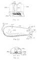
- FIG. 25illustrates reading a bar code with an optical reader according to an embodiment of the invention
- FIG. 26illustrates a top plan view of an optical reader according to an embodiment of the invention.
- FIG. 27illustrates a front elevation view of the optical reader viewed from line 27 — 27 of FIG. 26;
- FIG. 28illustrates a general functional block diagram of the components of an optical reader in accordance with an embodiment of the invention
- FIG. 29illustrates the optical reader of FIG. 26 with portions of the outer shell removed to show the interior components
- FIG. 30illustrates an enlarged view of the optical system of the optical reader while reading a bar code
- FIG. 31illustrates a perspective view of the detector unit used in an embodiment of the optical reader
- FIG. 32illustrates an exploded view of the detector unit of FIG. 31
- FIG. 33illustrates a top plan view of an optical reader according to another embodiment of the invention.
- FIG. 34illustrates a side elevation view of the optical reader of FIG. 33
- FIG. 35illustrates a front elevation view of the optical reader viewed from line 35 — 35 of FIG. 33;
- FIG. 36illustrates a flowchart of one embodiment of the process for reading a bar code
- FIGS. 37 a and 37 billustrate an operation wherein a bar code is associated with a unique indicia
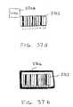
- FIG. 38 aillustrates a diagrammatic view of a unique ornamental bar code for being associated with a product
- FIG. 38 billustrates an alternate embodiment of an ornamental bar code
- FIG. 39illustrates a product on which the bar code of FIG. 38 a is disposed
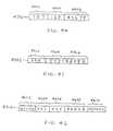
- FIG. 40illustrates a unique bar code for encoding machine-readable information
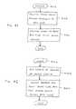
- FIG. 41illustrates a flowchart for one embodiment of a process for facilitating the manual reading of a bar code from the perspective of the bar code sponsor;
- FIG. 42illustrates a flowchart of the process from the user's perspective
- FIG. 43illustrates a diagrammatic view of one embodiment of a system for transmitting data from an optical reader
- FIG. 44illustrates a sample data packet from the message assembly circuitry of the system
- FIG. 45illustrates the sample data packet from the encryption circuitry of the system
- FIG. 46illustrates a sample message packet from the transmitting circuitry of the embodiment
- FIG. 47illustrates a flowchart for one embodiment of a process for transmitting data from an optical reader
- FIG. 48illustrates a flowchart for the sub-steps of performing further processing in the embodiment of FIG. 47.
- FIG. 49illustrates a flowchart for the sub-steps of assembling a message packet in the embodiment.
- FIG. 1there is illustrated a block diagram of a system for controlling a personal computer (“PC”) 112 via an audio tone transmitted over a wireless system utilizing a TV.
- PCpersonal computer
- the transmission station 101is comprised of a television program source 104 , which is operable to generate a program in the form of a broadcast signal comprised of video and audio. This is transmitted via conventional techniques along channels in the appropriate frequencies.
- the program sourceis input to a mixing device 106 , which mixing device is operable to mix in an audio signal.
- This audio signalis derived from an audio source 100 which comprises a coded audio signal which is then modulated onto a carrier which is combined with the television program source 104 .
- This signal combiningcan be done at the audio level, or it can even be done at the RF level in the form of a different carrier.
- the preferred methodis to merely sum the audio signal from the modulator 102 into the audio channel of the program that is generated by the television program source 104 .
- the output thereofis provided from the mixing device 106 in the form of broadcast signal to an antenna 107 , which transmits the information over the communication link 108 to an antenna 109 on the receive side.
- a conventional receiver 110such as a television is provided.
- This televisionprovides a speaker output which provides the user with an audible signal.
- Thisis typically associated with the program.
- the receiver 110 in the disclosed embodimentalso provides an audio output jack, this being the type RCA jack.
- This jackis utilized to provide an audio output signal on a line 113 which is represented by an audio signal 111 .
- This line 113provides all of the audio that is received over the communication link 108 to the PC 112 in the audio input port on the PC 112 .
- the audio signal generated by the advertiser data input device 100is audible to the human ear and, therefore, can be heard by the user. Therefore, no special filters are needed to provide this audio to the PC 112 .
- the PC 112is operable to run programs thereon which typically are stored in a program file area 116 . These programs can be any type of programs such as word processing programs, application programs, etc. In the disclosed embodiment, the program that is utilized in the system is what is referred to as a “browser.”
- the PC 112runs a browser program to facilitate the access of information on the network, for example, a global communication network known as the “Internet” or the World-Wide-Web (“Web”).
- the browseris a hypertext-linked application used for accessing information. Hypertext is a term used to describe a particular organization of information within a data processing system, and its presentation to a user.
- Hypertext systemsuse a large number of units of text or other types of data such as image information, graphical information, video information, or sound information, which can vary in size.
- a collection of such units of informationis termed a hypertext document, or where the hypertext documents employ information other than text, hypermedia documents.
- Multimedia communicationsmay use the Hypertext Transfer Protocol (“HTTP”), and files or formatted data may use the Hypertext Markup Language (“HTML”).
- HTTPHypertext Transfer Protocol
- HTMLHypertext Markup Language
- This formatting languageprovides for a mingling of text, graphics, sound, video, and hypertext links by “tagging” a text document using HTML.
- Data encoded using HTMLis often referred to as an “HTML document,” an “HTML page,” or a “home page.”
- HTML documentData encoded using HTML
- HTML pageData encoded using HTML
- home pageThese documents and other Internet resources may be accessed across the network by means of a network addressing scheme which uses a locator referred to as a Uniform Resource Locator (“URL”), for example, “http://www.digital.com.”
- URLUniform Resource Locator
- the Internetis one of the most utilized networks for interconnecting distributed computer systems and allows users of these computer systems to exchange data all over the world.
- Many private networksfor example, corporate or commercial networks.
- Standard protocolssuch as the Transport Control Protocol (“TCP”) and the Internet Protocol (“IP”) provide a convenient method for communicating across these diverse networks. These protocols dictate how data are formatted and communicated.
- TCPTransport Control Protocol
- IPInternet Protocol
- the protocolsare layered in an IP stack. At higher levels of the IP stack, such as the application layer (where HTTP is employed), the user information is more readily visible, while at lower levels, such as the network level (where TCP/IP are used), the data can merely be observed as packets or a stream of rapidly moving digital signals.
- Superimposed on the Internetis a standard protocol interface for accessing Web resources, such as servers, files, Web pages, mail messages, and the like. One way that Web resources can be accessed is by browsers made by Netscape® and Microsoft Internet Explorer®.
- the usercan load this program with the appropriate keystrokes such that a browser window will be displayed on a display 118 .
- the usercan run the browser program on the PC 112 such that the browser window is displayed on the display 118 .
- the usercan also view display 118 .
- the first operationis to extract the audio information within the received audio signal in the form of digital data, and then transmit this digital data to a defined location on the global communication network via a modem connection 114 . This connection will be described hereinbelow.
- This informationwill be relayed to a proprietary location and the instructions sent back to the PC 112 as to the location of the advertiser associated with the code, and the PC 112 will then effect a communication link to that location such that the user can view on the display 118 information that the advertiser, by the fact of putting the tone onto the broadcast channel, desires the viewer to view.
- This informationcan be in the form of interactive programs, data files, etc.
- the tonewhen an advertisement appears on the television, the tone can be generated and then additional data displayed on the display 118 .
- a streaming video programcould be played on the PC received over the network, which streaming video program is actually longer than the advertising segment on the broadcast.
- Another examplewould be a sports game that would broadcast the tone in order to allow a user access to information that is not available over the broadcast network, such as additional statistics associated with the sports program, etc.
- an advertiseris allowed the ability to control a user's PC 112 through the use of tones embedded within a program audio signal.
- the disclosed embodimentutilizes particular routing information stored in the PC 112 which allows the encoded information in the received audio signal to route this information to a desired location on the network, and then allow other routing information to be returned to the PC 112 for control thereof to route the PC 112 to the appropriate location associated with that code.
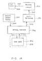
- the computer 204comprises an internal audio or “sound” card 206 for receiving the transmitted audio signal through receive antenna 109 and receiver 110 .
- the sound card 206typically contains analog-to-digital circuitry for converting the analog audio signal into a digital signal. The digital signal may then be more easily manipulated by software programs.
- the receiver 110separates the audio signal from the video signal.
- a special trigger signal located within the transmitted advertiser audio signaltriggers proprietary software running on the computer 204 which launches a communication application, in this particular embodiment, the web browser application located on the PC 204 . Coded advertiser information contained within the audio signal is then extracted and appended with the address of a proprietary server located on the communication network.
- the remote server addressis in the form of a URL.
- This appended datain addition to other control codes, is inserted directly into the web browser application for automatic routing to the communication network.
- the web browser running on PC 204and communicating to the network with an internal modem 208 , in this embodiment, transmits the advertiser information to the remote server.
- the remote servercross-references the advertiser product information to the address of the advertiser server located on the network.
- the address of the advertiser serveris routed back through the PC 204 web browser to the advertiser server.
- the advertiser product informationis returned to PC 204 to be presented to the viewer on display 118 .
- the particular advertiser product information displayedis contained within the advertiser's web page 212 .
- the audio signalis audible to the human ear. Therefore the audio signal, as emitted from the TV speakers, may be input to the sound card 206 via a microphone. Furthermore, the audio signal need not be a real-time broadcast, but may be on video tapes, CDs, DVD, or other media which may be displayed at a later date. With the imminent implementation of high definition digital television, the audio signal output from the TV may also be digital. Therefore, direct input into a sound card for A/D purposes may not be necessary, but alternative interfacing techniques to accommodate digital-to-digital signal formats would apply.
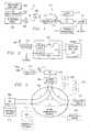
- a source PC 302similar to PCs 204 and 112 , connected to a global communication network (“GCN”) 306 through an interface 304 .
- the audio signal 111is received by PC 302 through its sound card 206 .
- the audio signal 111comprises a trigger signal which triggers proprietary software into launching a web browser application residing on the PC 302 .
- the audio signal 111also comprises advertiser product information which is extracted and appended with URL information of an Advertiser Reference Server (“ARS”) 308 .
- ARS 308is a system disposed on the GCN 306 that is defined as the location to which data in the audio signal 111 is to be routed.
- data in the audio signal 111will always be routed to the ARS 308 , since a URL is unique on the GCN 306 .
- a database 310 of product codes and associated manufacturer URLsConnected to the ARS 308 is a database 310 of product codes and associated manufacturer URLs.
- the database 310undergoes a continual update process which is transparent to the user. As companies sign-on, i.e., subscribe, to this technology, manufacturer and product information is added to the database 310 without interrupting operation of the source PC 302 with frequent updates.
- the advertiser server address URLis obtained from the ARS database 310 , it and the request for the particular advertiser product information are automatically routed back through the web browser on PC 302 , over to the respective advertiser server for retrieval of the advertiser product information to the PC 302 .
- the disclosed inventiondiscusses a global communication network, the system is also applicable to LANs, WANs, and peer-to-peer network configurations. It should be noted that the disclosed architecture is not limited to a single source PC 302 , but may comprise a plurality of source PCs, e.g., PC 300 and PC 303 . Moreover, a plurality of ARS 308 systems and advertiser servers 312 may be implemented, e.g., ARS 314 , and advertiser server A 316 , respectively.
- the information transactionsin general, which occur between the networked systems of this embodiment, over the communication network, are the following.
- the web browser running on source PC 302transmits a message packet to the ARS 308 over Path “A.”
- the ARS 308decodes the message packet and performs a cross-reference function with product information extracted from the received message packet to obtain the address of an advertiser server 312 .
- a new message packetis assembled comprising the advertiser server 312 address, and sent back to the source PC 302 over Path “B.”
- a “handoff” operationis performed whereby the source PC 302 browser simply reroutes the information on to the advertiser server 312 over Path “C,” with the appropriate source and destination address appended.
- the advertiser server 312receives and decodes the message packet.
- the request-for-advertiser-product-informationis extracted and the advertiser 312 retrieves the requested information from its database for transmission back to the source PC 302 over Path “D.”
- the source PC 302then processes the information, i.e., for display to the viewer.
- the optional Path “E”is discussed hereinbelow. It should be noted that the disclosed methods are not limited to only browser communication applications, but may accommodate, with sufficient modifications by one skilled in the art, other communication applications used to transmit information over the Internet or communication network.
- the message packet 400 sent from the source PC 302 to ARS 308 via Path “A”comprises several fields.
- One fieldcomprises the URL of the ARS 308 which indicates where the message packet is to be sent.
- Another fieldcomprises the advertiser product code or other information derived from the audio signal 111 , and any additional overhead information required for a given transaction.
- the product codeprovides a link to the address of the advertiser server 312 , located in the database 310 .
- Yet another fieldcomprises the network address of the source PC 302 .
- network transmissionsare effected in packets of information, each packet providing a destination address, a source address, and data. These packets vary depending upon the network transmission protocol utilized for communication.
- messages packetshall refer to and comprise the destination URL, product information, and source address, even though more than a single packet must be transmitted to effect such a transmission.
- ARS 308Upon receipt of the message packet 400 from source PC 302 , ARS 308 processes the information in accordance with instructions embedded in the overhead information. The ARS 308 specifically will extract the product code information from the received packet 400 and, once extracted, will then decode this product code information. Once decoded, this information is then compared with data contained within the ARS advertiser database 310 to determine if there is a “hit.” If there is no “hit” indicating a match, then information is returned to the browser indicating such. If there is a “hit,” a packet 402 is assembled which comprises the address of the source PC 302 , and information instructing the source PC 302 as to how to access, directly in a “handoff” operation, another location on the network, that of an advertiser server 312 .
- the source PC 302can then access the advertiser server 312 .
- the ARS 308transmits the packet 402 back to source PC 302 over Path “B.”
- the message packet 402comprises the address of the source PC 302 , the URL of the advertiser server 312 embedded within instructional code, and the URL of the ARS 308 .
- the message packet 402Upon receipt of the message packet 402 by the source PC 302 , the message packet 402 is disassembled to obtain pertinent routing information for assembly of a new message packet 404 .
- the web browser running on source PC 302is now directed to obtain, over Path “C,” the product information relevant to the particular advertiser server 312 location information embedded in message packet 404 .
- the message packet 404 for this transactioncomprises the URL of the advertiser server 312 , the request-for-product-information data, and the address of the source PC 302 .
- advertiser server 312Upon receipt of the message packet 404 from source PC 302 , advertiser server 312 disassembles the message packet 404 to obtain the request-for-product-information data. The advertiser server 312 then retrieves the particular product information from its database, and transmits it over Path “D” back to the source PC 302 . Referring now to FIG. 4 d, the message packet 406 for this particular transaction comprises the address of the source PC 302 , the requested information, and the URL of the advertiser server 312 .
- the ARS 308may make a direct request for product information over Path “E” to advertiser server 312 .
- the ARS 308sends information to the advertiser server 312 instructing it to contact the source PC 302 .
- the message packet 408 for this transactionis illustrated in FIG. 4 e, which comprises the URL of the advertiser server 312 , the request-for-product-information data, and the address of the source PC 302 . Since product information is not being returned to the ARS 308 , but directly to the source PC 302 , the message packet 408 requires the return address to be that of the source PC 302 . The product information is then passed directly to PC 302 over Path “D.”
- decision block 500a proprietary application running resident on a source computer PC 302 (similar to PC 204 ) monitors the audio input for a special trigger signal. Upon detection of the trigger signal, data following the trigger signal is decoded for further processing, in function block 502 . In function block 504 , the data is buffered for further manipulation. In decision block 506 , a determination is made as to whether the data can be properly authenticated. If not, program flow continues through the “N” signal to function block 520 where the data is discarded. In function block 522 , the program then signals for a retransmission of the data. The system then waits for the next trigger signal, in decision block 500 .
- program flowcontinues through the “Y” signal path where the data is then used to launch the web browser application, as indicated in function block 508 .
- the web browserreceives the URL data, which is then automatically routed through the computer modem 208 to the network interface 304 and ultimately to the network 306 .
- the ARS 308responds by returning the URL of advertiser server 312 to the PC 302 .
- the web browserrunning on the source PC 302 , receives the advertiser URL information from the ARS 308 , and transmits the URL for the product file to the advertiser server 312 .
- the advertiser server 312responds by sending the product information to the source PC 302 for processing.
- the usermay obtain the benefits of this architecture by simply downloading the proprietary software over the network.
- Other methods for obtaining the softwareare well-known; for example, by CD, diskette, or pre-loaded hard drives.
- the ARS 308may undergo when receiving the message packet 400 from the source PC 302 .
- decision block 600the ARS 308 checks for the receipt of the message packet 400 . If a message packet 400 is not received, program flow moves along the “N” path to continue waiting for the message. If the message packet 400 is received, program flow continues along path “Y” for message processing.
- the ARS 308decodes the message packet 400 . The product code is then extracted independently in function block 604 in preparation for matching the product code with the appropriate advertiser server address located in the database 310 .
- function block 606the product code is then used with a lookup table to retrieve the advertiser server 312 URL of the respective product information contained in the audio signal data.
- the ARS 308then assembles message packet 402 for transmission back to the source PC 302 .
- Function block 610indicates the process of sending the message packet 402 back to the source PC 302 over Path “B.”
- the source PC 302receives the message packet 402 back from the ARS 308 and begins to decode the packet 402 .
- the URL of the advertiser product informationis extracted from the message packet 402 and saved for insertion into the message packet 404 to the advertiser server 312 .
- the message packet 404is then assembled and sent by the source PC 302 over Path “C” to the advertiser server 312 , in function block 704 .
- the advertiser server 312receives the message packet 404 from the source PC 302 , in function block 708 , and disassembles it.
- the product information locationis then extracted from the message packet 404 in function block 710 .
- the particular product informationis retrieved from the advertiser server 312 database for transmission back to the source PC 302 .
- the product informationis assembled into message packet 406 and then transmitted back to the source PC 302 over Path “D.”
- the advertiser product information contained in the message packet 406 received from the advertiser server 312is then extracted and processed in function block 716 .
- a web browser application on a source PC 302is automatically launched and computer display 800 presents a browser page 802 .
- Proprietary software running on the source PC 302processes the audio signal data after being digitized through the sound card 206 .
- the softwareappropriately prepares the data for insertion directly into the web browser by extracting the product information code and appending keystroke data to this information.
- a URL page 804is opened in response to a Ctrl-O command added by the proprietary software as the first character string. Opening URL page 804 automatically positions the cursor in a field 806 where additional keystroke data following the Ctrl-O command will be inserted.
- the hypertext protocol preamble http://is inserted into the field 806 .
- URL information associated with the location of the ARS 308is inserted into field 806 .
- URL dataare the characters /? to allow entry of variables immediately following the /? characters.
- the variable followingis the product information code received in the audio signal.
- the product code informationalso provides the cross-reference information for obtaining the advertiser URL from the ARS database 310 .
- a carriage returnis added to send the URL/product data and close the window 804 .
- the message packet 400After the message packet 400 is transmitted to the ARS 308 from the source PC 302 , transactions from the ARS 308 , to the source PC 302 , to the advertiser server 312 , and back to the source PC 302 , occur quickly and are transparent to the viewer. At this point, the next information the viewer sees is the product information which was received from the advertiser server 312 .
- a video source 902is provided which is operable to provide an audio output on an audio cable 901 which provides routing information referred to by reference numeral 904 .
- the routing information 904is basically information contained within the audio signal. This is an encoded or embedded signal.
- the important aspect of the routing information 904is that it is automatically output in realtime as a function of the broadcast of the video program received over the video source 902 . Therefore, whenever the program is being broadcast in realtime to the user 908 , the routing information 904 will be output whenever the producer of the video desires it to be produced.
- the box 902 representing the video sourcecould be any type of media that will result in the routing information being output.
- the audio informationis then routed to a PC 906 , which is similar to the PC 112 in FIG. 1.
- a user 908is interfaced with the PC to receive information thereof, the PC 906 having associated therewith a display (not shown).
- the PC 906is interfaced with a network 910 , similar to the network 306 in FIG. 3 .
- This network 910has multiple nodes thereon, one of which is the PC 906 , and another of which is represented by a network node 912 which represents remote information.
- the object of the present embodimentis to access remote information for display to the user 908 by the act of transmitting from the video program in block 902 the routing information 904 .
- This routing information 904is utilized to allow the PC 906 which has a network “browser” running thereon to “fetch” the remote information at the node 912 over the network 910 for display to the user 908 .
- This routing information 904is in the form of an embedded code within the audio signal, as was described hereinabove.
- the PC 906is split up into a couple of nodes, a first PC 1002 and a second PC 1004 .
- the PC 1002resides at the node associated with the user 908
- the PC 1004resides at another node.
- the PC 1004represents the ARS 308 of FIG. 3 .
- the PC 1004has a database 1006 associated therewith, which is basically the advertiser database 310 . Therefore, there are three nodes on the network 910 necessary to implement the disclosed embodiment, the PC 1002 , the PC 1004 and the remote information node 912 .
- the routing information 904is utilized by the PC 1002 for routing to the PC 1004 to determine the location of the remote information node 912 on the network 910 . This is returned to the PC 1002 and a connection made directly with the remote information node 912 and the information retrieved therefrom to the user 908 .
- the routing information 904basically constitutes primary routing information.
- FIG. 11there is illustrated a diagrammatic view of how the network packet is formed for sending the primary routing information to the PC 1004 .
- the primary routing informationoccupies a single field which primary routing information is then assembled into a data packet with the secondary routing information for transfer to the network 910 . This is described hereinabove in detail.
- the video source 902has associated therewith an optical region 1202 , which optical region 1202 has disposed therein an embedded video code.
- This embedded video codecould be relatively complex or as simple as a grid of dark and white regions, each region in the grid able to have a dark color for a logic “1” or a white region for a logic “0. ” This will allow a digital value to be disposed within the optical region 1202 .
- a sensor 1204can then be provided for sensing this video code. In the example above, this would merely require an array of optical detectors, one for each region in the grid to determine whether this is a logic “1” or a logic “0” state.
- One of the sensed videois then output to the PC 906 for processing thereof to determine the information contained therein, which information contained therein constitutes the primary routing information 904 . Thereafter, it is processed as described hereinabove with reference to FIG. 9 .
- the PC 906has associated therewith a profile database 1302 , which profile database 1302 is operable to store a profile of the user 908 .
- This profileis created when the program, after initial installation, requests profile information to be input in order to activate the program.
- a unique IDthat is provided to the user 908 in association with the browser program that runs on the PC 906 .
- Thisis stored in a storage location represented by a block 1304 .
- This ID 1304is accessible by a remote location as a “cookie” which is information that is stored in the PC 906 in an accessible location, which accessible location is actually accessible by the remote program running on a remote node.
- the ARS 308which basically constitutes the PC 1004 of FIG. 10, is operable to have associated therewith a profile database 1308 , which profile database 1308 is operable to information store profiles for all of the users.
- the profile database 1308is a combination of the stored in profile database 1302 for all of the PCs 906 that are attachable to the system. This is to be distinguished from information stored in the database 310 of the ARS 308 , the advertiser's database, which contains intermediate destination tables.
- the routing information in the primary routing information 904is forwarded to the ARS 308 and extracted from the original data packet, the lookup procedure described hereinabove can then be performed to determine where this information is to be routed.
- the profile database 1302is then utilized for each transaction, wherein each transaction in the form of the routing information received from the primary routing information 904 is compared to the destination tables of database 310 to determine what manufacturer is associated therewith.
- the associated ID 1304 that is transmitted along with the routing information in primary routing information 904is then compared with the profile database 1308 to determine if a profile associated therewith is available.
- This informationis stored in a transaction database 1310 such that, at a later time, for each routing code received in the form of the information in primary routing information 904 , there will associated therewith the IDs 1304 of each of the PCs 906 .
- the associated profiles in database 1308which are stored in association with IDs 1304 , can then be assembled and transmitted to a subscriber as referenced by a subscriber node 1312 on the network 910 .
- the ARS 308can do this in two modes, a realtime mode or a non-realtime mode.
- a PC 906accesses the advertiser database 310 , that user's profile information is uploaded to the subscriber node 1312 .
- billing informationis generated for that subscriber 1312 which is stored in a billing database 1316 . Therefore, the ARS 308 has the ability to inform the subscriber 1312 of each transaction, bill for those transactions, and also provide to the subscriber 1312 profile information regarding who is accessing the particular product advertisement having associated therewith the routing information field 904 for a particular routing code as described hereinabove. This information, once assembled, can then be transmitted to the subscriber 1312 and also be reflected in billing information and stored in the billing information database 1316 .
- FIG. 14there is illustrated a flowchart depicting the operation for storing the profile for the user.
- the programis initiated in a block 1402 and then proceeds to a function block 1404 , wherein the system will prompt for the profile upon initiation of the system.
- This initiationis a function that is set to activate whenever the user initially loads the software that he or she is provided. The purpose for this is to create, in addition to the setup information, a user profile.
- the programwill flow to a decision block 1406 to determine whether the user provides basic or detailed information. This is selectable by the user. If selecting basic, the program will flow to a function block 1408 wherein the user will enter basic information such as name and serial number and possibly an address.
- the original prompt in function block 1404would have offers for such things as coupons, discounts, etc., if the user will enter additional information. If the user selects this option, the program flows from the decision block 1406 to a function block 1410 . In the function block 1410 , the user is prompted to enter specific information such as job, income level, general family history, demographic information and more. There can be any amount of information collected in this particular function block.
- the programwill then flow to a function block 1412 where this information is stored locally.
- the programthen flows to a decision block 1414 to then go on-line to the host or the ARS 308 .
- the useris prompted to determine whether he or she wants to send this information to the host at the present time or to send it later. If he or she selects the “later” option, the program will flow to a function block 1415 to prompt the user at a later time to send the information.
- the userwill not be able to utilize the software until the profile information is sent to the host. Therefore, the user may have to activate this at a later time in order to connect with the host.
- the programwill flow to the function block 1416 to initiate the connect process and then to a decision block 1418 to determine if the connection has been made. If not, the program will flow along a “N” path to a decision block 1420 which will timeout to an error block 1422 or back to the input of the connect decision block 1418 . The program, once connected, will then flow along a “Y” path from decision block 1418 to a function block 1428 to send the profile information with the ID of the computer or user to the host.
- the IDis basically, as described hereinabove, a “cookie” in the computer which is accessed by the program when transmitting to the host.
- the programwill then flow to a function block 1430 to activate the program such that it, at later time, can operate without requiring all of the setup information. In general, all of the operation of this flowchart is performed with a “wizard” which steps the user through the setup process. Once complete, the program will flow to a Done block 1432 .
- FIG. 15there is illustrated a flowchart depicting the operation of the host when receiving a transaction.
- the programis initiated at a Start block 1502 and then proceeds to decision block 1504 , wherein it is determined whether the system has received a routing request, i.e., the routing information 904 in the form of a tone, etc., embedded in the audio signal, as described hereinabove with respect to FIG. 9 .
- the programwill loop back around to the input of decision block 1504 until the routing request has been received.
- the programwill flow along the “Y” path to a function block 1506 to receive the primary routing information and the user ID. Essentially, this primary routing information is extracted from the audio tone, in addition to the user ID.
- the programthen flows to a function block 1508 to look up the manufacturer URL that corresponds to the received primary routing information and then return the necessary command information to the originating PC 112 in order to allow that PC 112 to connect to the destination associated with the primary routing information. Thereafter, the program will flow to a function block 1510 to update the transaction database 1310 for the current transaction.
- the routing information 904will be stored as a single field with the associated IDs.
- the profile database 1308has associated therewith detailed profiles of each user on the system that has activated their software in association with their ID. Since the ID was sent in association with the routing information, what is stored in the transaction database 1310 is the routing code, in association with all of the IDs transmitted to the system in association with that particular routing code. Once this transaction database 1310 has been updated, as described hereinabove, the transactions can be transferred back to the subscriber at node 312 with the detailed profile information from the profile database 1308 .
- the profile informationcan be transmitted back to the subscriber or manufacturer at the node 312 in realtime or non-realtime.
- a decision block 1512is provided for this, which determines if the delivery is realtime. If realtime, the program will flow along a “Y” path to a function block 1514 wherein the information will be immediately forwarded to the manufacturer or subscriber. The program will then flow to a function block 1516 wherein the billing for that particular manufacturer or subscriber will be updated in the billing database 1316 . The program will then flow into an End block 1518 . If it was non-realtime, the program moves along the “N” path to a function block 1520 wherein it is set for a later delivery and it is accrued in the transaction database 1310 . In any event, the transaction database 1310 will accrue all information associated with a particular routing code.
- a cola manufacturerwere to provide a promotional advertisement on, for example, television, indicating that a new cola was going to be placed on the shelf and that the first 1000 purchasers, for example, scanning their code into the network would receive some benefit, such as a chance to win a trip to some famous resort in Florida or some other incentive, the manufacturer would have a very good idea as to how well the advertisement was received. Further, the advertiser would know where the receptive markets were. If this advertiser, for example, had placed the television advertisement in ten cities and received overwhelming response from one city, but very poor response from another city, he would then have some inclination to believe that either the one poor-response city was not a good market or that the advertising medium he had chosen was very poor. Since the advertiser can obtain a relatively instant response and also content with that response as to the demographics of the responder, very important information can be obtained in a relatively short time.
- the disclosed embodimentis not limited to a single source PC 302 , but may encompass a large number of source computers connected over a global communication network. Additionally, the embodiment is not limited to a single ARS 308 or a single advertiser server 312 , but may include a plurality of ARS and advertiser systems, indicated by the addition of ARS 314 and advertiser server A 316 , respectively. It should also be noted that this embodiment is not limited only to global communication networks, but also may be used with LAN, WAN, and peer-to-peer configurations.
- the disclosed embodimentis not limited to a personal computer, but is also applicable to, for example, a Network Computer (“NetPC”), a scaled-down version of the PC, or any system which accommodates user interaction and interfaces to information resources.
- Network Computera Network Computer
- the disclosed embodimentis not limited to a personal computer, but is also applicable to, for example, a Network Computer (“NetPC”), a scaled-down version of the PC, or any system which accommodates user interaction and interfaces to information resources.
- NetPCNetwork Computer
- One typical application of the above noted techniqueis for providing a triggering event during a program, such as a sport event.
- thismay be generated by an advertiser.
- an advertisercontracted for 15 seconds worth of advertising time, they could insert within their program a tone containing the routing information.
- This routing informationcan then be output to the user's PC 302 which will cause the user's PC 302 to, via the network, obtain information from a remote location typically controlled by the advertiser.
- Thiscould be in the form of an advertisement of a length longer than that contracted for. Further, this could be an interactive type of advertisement.
- An important aspect to the type of interaction between the actual broadcast program with the embedded routing information and the manufacturer's siteis the fact that there is provided information as to the user's PC 302 and a profile of the user themselves. Therefore, an advertiser can actually gain realtime information as to the number of individuals that are watching their particular advertisement and also information as to the background of those individuals, profile information, etc. This can be a very valuable asset to an advertiser.
- the producer of the programcan allow the user to automatically access additional information that is not displayed on the screen.
- additional informationFor example, in a sporting event, various statistics can be provided to the user from a remote location, merely by the viewer watching the program. When these statistics are provided, the advertiser can be provided with profile information and background information regarding the user. This can be important when, for example, the user may record a sports program. If the manufacturer sees that this program routing code is being output from some device at a time later than the actual broadcast itself, this allows the advertisers to actually see that their program is still being used and also what type of individual is using it.
- the broadcastercould determine the same and actually bill the advertiser an additional sum for a later broadcast. This is all due to the fact that the routing information automatically, through a PC and a network, will provide an indication to the advertiser the time at which the actual information was broadcast.
- the different type of medium that can be utilized with the above embodimentare such things as advertisements, which are discussed hereinabove, contests, games, news programs, education, coupon promotional programs, demonstration media (demos), and photographs, all of which can be broadcast on a private site or a public site. This all will provide the ability to allow realtime interface with the network and the remote location for obtaining the routed information and also allow for realtime billing and accounting.
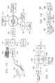
- a bar code scanning input device 1600is provided by a input device distributor to customers and is associated with that distributor via a input device ID stored therein.
- the input device 1600is either sold or freely distributed to customers for use with their personal computing systems. Since more and more products are being sold using bar codes, it can be appreciated that a user having the input device 1600 can scan bar codes of a multitude of products in order to obtain more information. Information about these products can be made immediately available to the user from the manufacturer for presentation by the user's computer 302 . Beyond simply displaying information about the product in which the user is interested, the input device distributor may include additional advertising information for display to the user such as information about other promotions or products provided or sold by the input device distributor.
- advertisersmay provide catalogs of advertisements or information in newspapers or periodicals where the user simply scans the bar code associated with the advertisement using the input device 1600 to obtain further information.
- a paper source 1602having contained thereon an advertisement 1604 and an associated bar code 1606 .
- the disclosed conceptis not limited to scanning of bar codes 1606 from paper sources 1602 , but is also operable to scan a bar code 1606 on the product itself.
- the input device 1600can be any type of device that will scan any type of image having information encoded therein.
- the userAfter obtaining the input device 1600 from the input device distributor, the user connects the input device 1600 to their PC 302 .
- input device 1600reads bar code data 1606 and the input device ID into a “wedge” interface 1608 for conversion into keyboard data, which keyboard data is passed therefrom into the keyboard input port of PC 302 .
- the importance of the input device IDwill be discussed in more detail hereinbelow.
- the wedge interface 1608is simply an interface box containing circuitry that accommodates inputs from both the scanning input device 1600 and a computer keyboard 1610 . This merely allows the information scanned by the input device 1600 to be input into the PC 302 . In the disclosed embodiment, the wedge interface 1608 will convert any information. The data output from the input device 1600 is passed into the wedge interface 1608 for conversion into keyboard data which is readily recognizable by the PC 302 . Therefore, the input device 1600 is not required to be connected to a separate port on the PC 302 . This data is recognized as a sequence of keystrokes. However, the output of the input device 1600 can be input in any manner compatible with the PC 302 .
- the wedge interface 1608When not receiving scanner data, the wedge interface 1608 simply acts as a pass-through device for keyboard data from the keyboard 1610 . In any case, the information is ultimately processed by a processor in the PC 302 and can be presented to the user on a display 1612 .
- the wedge interface 1608is operable to provide a decoding function for the bar code 1606 and conversion thereof to keystroke input data.
- the product code of a productis provided in the form of a bar code 1606 .
- This bar code 1606is the “link” to a product.
- the disclosed embodimentis operable to connect that product information contained in the bar code 1606 with a web page of the manufacturer of that product by utilizing the bar code 1606 as the product “identifier.”
- the program operating on the PC 302provides routing information to the ARS 308 after launching the browser on the PC 302 and connecting to the ARS 308 over the GCN 306 , which ARS 308 then performs the necessary steps to cause the browser to connect to the manufacturer web site, while also providing for an accounting step, as will be described in more detail hereinbelow.
- the bar code 1606by itself is incompatible with any kind of network for the purposes of communication therewith. It is primarily provided for a retail-type setting. Therefore, the information contained in the bar code 1606 , by itself, does not allow for anything other than identification of a product, assuming that one has a database 1614 containing information as to a correlation between the product and the bar code 1606 .
- the wedge interface 1608is operable to decode the bar code 1606 to extract the encoded information therein, and append to that decoded bar code information relating to an ID for the input device 1600 . This information is then forwarded to the ARS 308 by the resident program in the PC 302 . This is facilitated by intermediate routing information stored in the program indicating to which node on the GCN 306 the scanned bar code information is to be sent, i.e., to the ARS 308 . It is important to note that the information in the bar code 1606 must be converted from its optical image to numerical values which are then ultimately input to the keyboard input port of PC 302 and converted into data compatible with communication software residing on the PC 302 (in this case, HTML language for insertion into a browser program).
- the resident programlaunches the browser program and then assembles a communication packet comprised of the URL of the ARS 308 , the input device ID and the user ID. If another type of communications program were utilized, then it would have to be converted into language compatible with that program. Of course, a user could actually key in the information on the bar code 102 and then append the appropriate intermediate routing information thereafter. As will be described hereinbelow, the intermediate routing information appended thereto is the URL of the ARS 308 disposed on the GCN 306 .
- the PC 302hosts input device software which is operable to interpret data transmitted from the input device 1600 , and to create a message packet having the scanned product information and input device ID, routing information, and a user ID which identifies the user location of the input device 1600 .
- the input device softwareloads at boot-up of the PC 302 and runs in the background.
- the wedge interface 1608outputs a keystroke code (e.g., ALT-F10) to bring the input device program into the foreground for interaction by the operating system.
- the input device programthen inserts the necessary information into the browser program.
- the message packetis then transmitted to interface 304 across the global communication network 306 to the ARS 308 .
- the ARS 308interrogates the message packet and performs a lookup function using the ARS database 310 . If a match is found between particular parameters of the message packet, a return message packet is sent back to the PC 302 for processing.
- the input device program running on PC 302functions to partition the browser window displayed to the user into several individual areas. This is for the purpose of preparing to present to the user selected information in each of the individual areas (also called “framing”).
- the selected informationcomprises the product information which the user requested by scanning the bar code 1606 using the input device 1600 , information about the input device distributor which establishes the identity of the company associated with that particular input device 1600 , and at least one or more other frames which may be advertisements related to other products that the input device distributor sells. Note that the advertisements displayed by the input device distributor may be related to the product of interest or totally unrelated.
- the input device distributormay generate an advertisement of a new soft drink being marketed by Company A, that it sells.
- the input device distributormay also structure the display of information to the user such that a user requesting product information of a Product X may get the requested information of Product X along with advertisements for a competing item Product Y. Essentially, the input device distributor is free to generate any advertisement to the user in response to the user requesting product information.
- the return message packet transmitted from the ARS 308 to the PC 302is then transmitted back across the GCN 306 to the advertiser server 312 .
- the advertiser server 312restructures the message packet and appends the particular product information for transmission back to the PC 302 .
- the PC 302Upon receiving the particular advertiser information from advertiser server 312 , the PC 302 then retransmits a message to the input device distributor site 1616 and E-commerce site 1618 to obtain the information that needs to be framed in the browser window displayed to the user.
- the input device 1600is associated with the input device distributor by way of a input device ID such that scanning a product bar code 1606 in order to obtain information about that particular product generates one or more responses from one or more remote sites disposed on the GCN 306 .
- the input device IDStored in the input device 1600 is the input device ID which establishes its relationship to the input device distributor.
- Proprietary input device softwarerunning on the PC 302 operates to decode scanned bar code information and the input device ID received from the input device 1600 and wedge interface 1608 , and also provides a unique user ID for establishing the location of the user of the input device 1600 .
- the input device softwarealso assembles message packets and works in conjunction with the on-board communication software (e.g., a browser) to automatically route the message packets across the GCN 306 such that the one or more remote sites disposed on the GCN 306 return information to be framed for presentation to the user.
- the on-board communication softwaree.g., a browser
- a microcontroller 1700provides conversion of the data from the input device 1600 and controls interfacing of the keyboard 1610 and input device 1600 with the PC 302 .
- the microcontroller 1700has contained therein a memory 1702 or it can have external memory.
- the input device interfaces 1704comprise a serial data line, a ground line, and a power line.
- the keyboard interfaces 1708comprise a serial data line, a ground line, a clock line, and a power line.
- the PC 302provides a clock line, a power line, a serial data, and a ground line for input to the microcontroller 1700 .
- the microcontroller 1700is operable to receive signals from the keyboard 1610 and transfer the signals to the PC 302 as keyboard signals. Operation with the keyboard 1610 is essentially a “pass-through” procedure. Data output from the keyboard 1610 is already in keyboard format, and therefore requires no conversion by the wedge interface 1608 . With respect to the input device 1600 , the serial data is not compatible with a keyboard 1610 and, therefore, it must be converted into a keyboard format in order to allow input thereof to the keyboard input of the PC 302 .
- the microcontroller 1700performs this function after decoding this bar code information, and conversion of this bar code information into an appropriate stream of data which is comprised of the bar code information and the appended URL.
- This appended URLwill be pre-stored in the memory 1702 and is programmable at the time of manufacture.
- the memory 1702is illustrated as being contained within the microcontroller 1702 to provide a single chip solution. However, this could be external memory that is accessible by the microcontroller 1702 . Therefore, the microcontroller 1700 provides an interface between the input device 1600 and the keyboard 1610 to the PC 302 which allows the input device 1600 to receive coded information and convert it to keyboard strokes or, alternatively, to merely pass-through the keystrokes from the keyboard 1610 . Therefore, the user need not install any type of plug-in circuit board into the motherboard of the PC 302 in order to provide an interface to the input device 1600 ; rather, the user need only utilize the already available keyboard port in order to input the appropriate data into the system.
- the microcontroller 1700comprises a PIC16C73 microcontroller by Microchip TechnologiesTM.
- the PIC16C73 deviceis a low cost CMOS8-bit microcontroller with an integrated analog-to-digital converter.
- the PIC16C73 deviceas illustrated in the disclosed embodiment, has 192 bytes of RAM and 4k ⁇ 4 of EPROM memory.
- the microcontroller 1700can accommodate asynchronous or synchronous inputs from input devices connected to it. In this disclosed embodiment, communication to the keyboard 1610 is synchronous while it is asynchronous when communicating with input device 1600 .
- bar code information of the bar code 1606is input into the keyboard input port of the PC 302 , disclosed methods may also be advantageously utilized with high speed port architectures such as Universal Serial Bus (“USB”) and IEEE 1394.
- USBUniversal Serial Bus
- IEEE 1394IEEE 1394
- Bar codesare structured to be read in either direction. Timing considerations need to be addressed because of the variety of individuals scanning the bar code introduce a wide variety of scan rates. Bar codes use bars of varying widths. The presence of a black bar generates a positive pulse, and the absence of a black bar generates no pulse. Each character of a conventional bar code has associated therewith seven pulses or bars. Depending on the width of the bars, the time between pulses varies. In this disclosed embodiment, the interface circuitry 1608 performs a “running” calculation of the scan time based upon the rising edge of the pulses commencing with the leader or header information. The minimum and maximum scans times are calculated continuously in software with the interface 1608 during the scanning process to ensure a successful scan by the user.
- the message packet 1800comprises a number of bits of information including the bar code information 1802 obtained from the user scanning the bar code 1606 with the input device 1600 ; the input device ID 1804 which is embedded in a memory in the input device 1600 and identifies it with a particular input device distributor; and a user ID 1806 which is derived from the software running on the PC 302 and which identifies uniquely with the user location.
- the message packetincludes other necessary information for the proper transmission for point to point.
- FIG. 19there is illustrated a more detailed block diagram of the routing of the message packets in order to present the framed information to the user.
- a input device programrunning on the user PC 302 is operable to interpret the information output by the input device 1600 and generate a message packet for transmission over the GCN 306 .
- the input device programassembles the message packet such that it is directed to the ARS 308 disposed on the GCN 306 .
- the message packetcontains several pieces of information including the input device ID 1804 which links it to the input device distributor, the user ID 1806 which identifies the particular user using the input device 1600 , and bar code information 1802 describing a particular product of interest to the user.
- This message from the PC 302is transmitted over a path 1900 to the ARS 308 where the ARS database 310 is accessed to cross reference the ID information 1804 and bar code information 1802 to a particular advertiser and input device distributor.
- the ARS 308returns a message packet over a path 1902 to the user PC 302 which contains routing information as to the location of various other sites disposed on the GCN 306 , for example, the advertiser server 312 and input device distributor site 1616 .
- the ARS 308can also be provided by the ARS 308 which more closely targets the particular user of the input device 1600 . For example, if it is known that a particular input device 1600 is sold in a certain geographic area, this information can be useful in targeting the particular user with certain advertising information relevant to that geographic area.
- the information returned from the ARS 308 over path 1902provides enough information for the input device program running on the user PC 302 to identify a number of other sites disposed on the GCN 306 .
- the user PC 302then processes the return message packet and routes another message packet over a path 1904 to the advertiser server 312 .
- the advertiser server 312then returns product information of the particular product in which the user was interested back to the user PC 302 over a path 1906 .
- the user PC 302routes information (e.g., the URL of the input device distributor site and the user profile) to the input device distributor site 1616 over a path 1908 in order to obtain information back over a path 1910 for framing any banners which identify the input device distributor. Additionally, the user PC 302 forwards a message packet to the E-commerce site 1618 over a path 1912 in order to return information regarding any particular advertisements the input device distributor wants to display to the user. The advertisements are returned to the PC 302 over a path 1914 .
- informatione.g., the URL of the input device distributor site and the user profile
- FIG. 20there is illustrated a block diagram of a browser window according to the disclosed embodiment.
- the browser window 2000is partitioned into a plurality of areas for framing specific information.
- a bar code area 2002displays that product information in which the user was interested;
- an input device-specific area 2004displays information about the input device distributor; and
- an E-commerce area 2006displays advertising information that the input device distributor selects for display according to this particular user and input device 1600 .
- a program operable to process scanned bar code information with the unique input device 1600develops the browser window by partitioning it into specific areas for the framing of information. Therefore, information returned from the E-commerce site 1608 is passed through the GCN 306 to the particular E-commerce frame 2006 .
- information about the particular product of interestis returned from the advertiser site 312 across the GCN 306 to the particular bar code specific area 2002 .
- Information placed in the input device specific area 2004is information about the input device distributor which is returned from the input device distributor site 1616 across GCN 306 .
- the ARS database 310contains a variety of information required to properly interrogate and assemble packets for obtaining information from the various sites disposed on the GCN 306 .
- the ARS database 310has a database structure 2100 which contains addresses for the web sites containing the product information requested by the user when scanning the bar code 1606 with the input device 1600 . Under a PRODUCT heading 2102 are listed the particular bar codes and associated routing information for addressing the respective server location.
- the ARS server 308may contain any number of advertisers having unique URL addresses associated therewith.
- the bar code 1606 of a particular productis associated with a unique URL address which routes any request for information of that product to that particular advertiser's site. Also part of the ARS database structure 2000 is a heading of INPUT DEVICE under which is the input device ID 1804 and the distributor associated with that input device ID 1804 .
- each distributorhas an ID embedded in the input device 1600 which uniquely identifies that input device with the particular distributor. Therefore, the unique input device ID 1804 needs to be listed with the respective distributors of that input device 1600 in order to process the information that needs to be framed and displayed to that particular user.
- Another heading under the ARS database structure 2100is a user heading 2106 which contains profile information associated with that particular user ID 1806 .
- the user ID 1806is obtained via the input device software running on the PC 302 and upon installation or subsequent configuration may request that the user input certain profile information which may be used to target that particular user with products and services which identify with that user profile.
- the ARS database structure 2100also contains an E-commerce heading 2108 which contains information related to the bar code 1606 and an advertisement that may be triggered by the request for that information.
- E-commerce heading 2108contains information related to the bar code 1606 and an advertisement that may be triggered by the request for that information.
- any bar code 1606 associated with a paper source 1602can be associated with the specific information in the ARS database 310 .
- a user wishing to obtain information about a specific soft drinkmay, in fact, trigger an advertising response of a competitor product.
- the user interested in information about that particular soft drinkmay also trigger information which is relevant to that particular product or a product which may normally be served in conjunction with that soft drink.
- the request for information regarding this particular bar coded productmay trigger advertisement from an E-commerce server 1618 related to information about finance and insurance.
- the information described as contained within the ARS database structure 2100is not limited to what has been described, but may comprise any number of pieces of information used to present desired information to the computer display of the user.
- FIG. 22there is illustrated a flowchart of the process of receiving information from the user's perspective, and according to the disclosed embodiment.
- the input device software running on the user's PC 302runs in the background until activated by output from the input device 1600 . Therefore, flow moves to a decision block 2200 where if a scanned input does not occur, flow moves out the “N” path and loops back to the input of decision block 2200 . On the other hand, if scanned input information is received, flow moves out the “Y” path to a function block 2202 where the input device software assembles a message packet containing the bar code information, the input device ID 1804 and the ARS 308 URL address.
- the browseris launched in which this information is placed for transmission to the ARS 308 .
- Flowthen moves to a function block 2204 where the browser is partitioned into any number of areas in which information is displayed when obtained from the input device distributor site 1616 , the E-commerce site 1618 , and the advertiser server 312 . It should be known that although three frames are shown in the particular window 2000 of this embodiment, the number of frames displayed in the window 2000 is limited only by the available real estate of the window 2000 area itself.
- Flowis then to a function block 2212 where the proprietary software working in conjunction with the hosted browser places the returned information into the respective frames of the window.
- the userviewing the display at PC 302 , then perceives a variety of information, one of which is the particular product information which he or she requested, in addition to input device distributor information, and possibly other advertisements based upon the user's profile.
- the ARS 308is operable to decode and process messages received from the GCN 306 . Therefore, flow is to a decision block 2300 where, if bar code information is not received, flow is out the “N” path with loop-back to its input. If bar code information has been received, flow is to a function block 2302 where a matching process occurs to link the bar-coded product information to its respective manufacturer.
- the ARS database 310also associates the URL address of the manufacturer's server. When a match is found, the ARS 308 begins to assemble a message packet of information for transmission back to the PC 302 , as indicated in function block 2304 .
- the message packetcontains the product information and the URL address of the manufacturer's website.
- Flowthen moves to a decision block 2306 where the input device ID 1804 is compared with the list of input device IDs issued by the particular input device distributor. If the input device ID 1804 is validated, flow moves out the “Y” path to a function block 2308 where the message packet is appended with the input device ID 1804 and distributor routing address.
- Flowthen moves to a decision block 2310 where the ARS 308 determines if any E-commerce information is to be associated with a particular input device ID 1804 . If so, flow is out the “Y” path to a function block 2312 where the message packet is appended with the E-commerce routing string.
- the E-commerce routing stringprovides addressing for the E-commerce server 1618 .
- Flowthen moves to a function block 2314 where all message packets are returned back to the PC 302 for processing.
- the E-commerce server 1618receives the message packet from the user PC 302 , as indicated in function block 2400 , and decodes the packet to perform a match with the bar coded information. Moving on to a decision block 2402 , if the match is unsuccessful, flow is out the “N” path to a function block 2404 where the match is rejected. A message may be returned to indicate that a problem occurred and the user may need to re-scan the product bar code 1606 . If a successful match occurs, flow moves out the “Y” path to a function block 2406 where the input device ID 1804 is matched with the bar code product information.
- the bar coded informationmay be distributed to customers over a large geographic area.
- the input device 1606may be coded for certain geographic areas.
- a input device 1600 having an XXX IDmay be restricted for sale in the Southwestern United States while a input device 1600 having a YYY ID may be sold only in the Northeast.
- geographic areasmay be targeted with advertising more appealing to that particular area.
- Advertising returned to the user PC 302may be focused further by obtaining a user profile when the software or input device 1600 are installed. In this way, advertising may be focused based upon the user profile. Therefore, flow moves to a function block 2408 to lookup the E-commerce action based upon the input device ID 1804 and the bar code information. Flow moves to a function block 2410 to assemble all the information into a packet for return to the user PC 302 . The product information and/or user profile information may be returned. Flow is then to a function block 2412 where the message packet is transmitted.
- Reader 2500typically includes an outer shell 2502 enclosing the working components and shaped for convenient manual grasping by the user. During operation, the front end 2504 of the reader 2500 is brought into contact with (or very close proximity to) a surface 2506 bearing the optical code to be read, for example barcode 2508 . The reading operation begins with the reader 2500 positioned at a starting position (shown in phantom and denoted by reference numeral 2510 ) to one side of the barcode 2508 .
- the reader 2500is then moved across the barcode 2508 as indicated by arrow 2512 to a final position (shown in phantom and denoted by reference numeral 2514 ) on the opposite side. Typically, the reader 2500 must be moved across the barcode 2508 at a substantially constant speed to ensure accurate reading of the symbol.
- internal circuitryproduces electronic output signals indicative of the symbol. These electronic output signals are provided to a computer (not shown), typically by means of a wired control cord 2516 . Alternately, the output signals may be sent from the reader 2500 to the computer using other known transmission technologies, for example using a wireless radio frequency (RF) link or a wireless infrared (IR) link.
- RFradio frequency
- IRwireless infrared
- the outer shell 2502 of the reader 2500will be constructed from multiple pieces to allow simple assembly of the internal components.
- the illustrated embodimentincludes an upper shell 2702 and a lower shell 2704 which form a hollow interior cavity within which the internal components are mounted.
- the upper shell 2702may have a generally semi-circular cross section and the lower shell 2704 may have a generally flat cross section.
- a scanning portal 2706is provided at the front end 2504 of reader 2500 to allow the interior components to project and collect radiant energy during the scanning operation.
- the scanning portal 2706is typically covered by a protective window 2708 which is transparent to the radiant energy wavelength used for scanning. Projection and/or collection lenses may be visible behind the window 2708 . For example, in FIG. 27, a collection lens 2710 and a projection lens 2712 are visible through the window 2708 .
- the front end 2504may be adapted to form a substantially flat bearing surface 2602 surrounding the scanning portal 2708 .
- the bearing surface 2602is preferably substantially perpendicular to the axis 2604 of the collection portion of the optical system.
- itmay be inset slightly behind the plane of the bearing surface 2602 .
- the window 2708may be further protected by the provision of pads 2606 on external shell 2502 which project slightly ahead of the bearing surface 2602 .
- the external shell 2502 of the reader 2500may be contoured to provide a comfortable grasp for the user and/or to have an attractive or distinctive shape.
- the upper shell 2702 of the reader 2500is smoothly contoured to provide a “streamlined” appearance in accordance with a common style used on other computer related devices such as a computer mouse, a track ball, etc.
- the exterior shellmay be contoured to provide a more distinctive appearance.
- the exterior surface of the outer shell 2502further provides an area 2607 for the placement of identifying or advertising indicia 2608 (shown in phantom).
- Such indiciamay be formed by printing or painting directly on the exterior surface of the reader 2500 , by the application of discrete labels, and/or by molding letters, designs or other indicia directly into the surface of the reader by means of injection molding or a similar process.
- Optical reader 3300has an exterior shell 3302 contoured to resemble an animal, in this case, a stylized cat. It will be readily appreciated that, except for the recontoured shell 3302 , the features described for the previous embodiment are present in substantially identical form in this embodiment, including the scanning portal 2706 , window 2708 , bearing surface 2602 and pads 2606 . In addition, identifying or advertising indicia 2608 may be placed on the stylized shell of reader 3300 in the same fashion as on the previous embodiment. It will further be apparent that the external shell of the reader can be contoured to resemble other animals, e.g., dogs, birds, reptiles, fish, etc. or other objects including automobiles, trucks, trains, aircraft, etc. without departing from the scope of the current invention.
- a radiant energy source 2802is provided for generating a radiant energy which will be used for illuminating a target region containing the barcode or other symbol to be scanned.
- the radiant energydenoted by arrow 2804 , is transmitted from the source 2802 into an optical system 2806 .
- the radiant energyis typically light in the visible wavelength, however light of infrared (IR) wavelength or other forms of radiant energy may be used.
- the optical system 2606which will be described in further detail below, directs the radiant energy (now denoted by arrow 2807 ) into a target region 2808 adjacent to the reader.
- the radiant energy directed into the target region 2808illuminates a barcode 2810 present therein and causes an image, denoted by arrow 2812 , of the barcode to be reflected back into another portion of the optical system 2806 .
- the reflected image of the barcodepasses through the optical system 2806 where it is processed to increase its contrast and decrease its luminance.
- the image, denoted now by arrow 2814is directed by the optical system 2806 onto a photodetector 2816 , which produces output electrical signals indicative of the radiant energy incident thereon.
- the output electrical signalsare routed to a decoder circuit 2820 , which utilizes electronic circuitry to decode the output electrical signals to provide an indication of the information contained in the barcode 2810 .
- the informationdenoted by reference numeral 2822 , is then transmitted to an external computer 2824 for further use or processing.
- the decoded information 2822is transmitted to the external computer 2824 in accordance with a known data interface format.
- Suitable data interface formats for transmission of the barcode information from the decoder circuit 2820 of the reader to an external computer 2824include an output signal which emulates computer keyboard keystrokes such as those in accordance with the PS/2 keyboard interface standard or the AT keyboard interface standard.
- the output signalsmay be formatted in accordance with other known data interface or communication standards, including the Universal Serial Bus (USB) standard, the RS-232 standard, the RS-423 standard, the IEEE 1394 (FIREWIRE) standard, the Integrated Drive Electronics (IDE) interface standard, the Enhanced Integrated Drive Electronics (EIDE) interface standard, the Asynchronous Transfer Mode (ATM) transmission standard, the Fiber Distributed Data Interface (FDDI) interface standard, the 8-Bit Industry Standard Architecture (ISA) bus standard, the 16-bit Industry Standard Architecture (ISA) bus standard, the VL-Bus bus standard, the Peripheral Component Interconnect (PCI) bus standard, the Personal Computer Memory Card International Association (PCMCIA) bus standard, the Centronics Parallel Port (CPP) standard, the Enhanced Parallel Port (EPP) standard, the Extended Capabilities Port (ECP) standard, the Small Computer System Interface (SCSI) interface standard, and network architecture standards including Ethernet and Token Ring network standards.
- USBUniversal Serial Bus
- RS-232Integrated Drive Electronics
- FIG. 29there is illustrated the optical reader 2500 with the upper shell removed to show the interior components.
- a printed circuit board (PCB) 2902is provided for physical mounting and electrical interconnection of the necessary electronic components comprising the decoder circuit and output signal interface circuit. These components include a microprocessor 2904 , memory (not shown), interface circuit 2906 , timing crystal 2908 and signal amplifiers 2910 . Note that for clarity of illustration, the individual circuit lines and many smaller components such as resistors which appear on the actual PCB 2902 are not illustrated in FIG. 29 .
- the PCB 2902may be mounted to the lower shell 2704 of the reader by means of locating pins 2912 molded into the shell and protruding through corresponding holes in the PCB. These holes can further receive screws (not shown) for securing the upper shell 2702 to the lower shell 2704 during final assembly.
- the portion of the PCB 2902 mounting amplifiers 2910is preferably enclosed is shielding material 2914 to prevent stray electrical signals from creating noise in the amplifier circuitry.
- the control cord 2516connects the reader 2500 to the external computer 2824 , entering the shell and passing through strain relief fitting 2916 for connecting to the PCB 2902 with electrical connector 2918 .
- the optical system 2806may be mounted to the front end of the PCB 2902 and further secured to the lower shell 2704 with locating pins 2920 and/or clips 2922 as needed.
- the radiant energy source 2802is typically mounted to the PCB 2902 and electrically connected thereto to receive electrical power.
- the radiant energy source 2802produces light or other radiant energy which is delivered into the optical system 2806 .
- the radiant energy source 2802is a light emitting diode (LED), however it will be apparent that a laser or other radiant energy source could be used.
- the optical system 2806comprises a projection portion 2924 for directing the radiant energy along a projection path extending from the radiant energy source 2802 to the target region 2926 .
- the optical system 2806further includes a collection portion 2928 for collecting the radiant energy reflected from a symbol (e.g., a barcode) when the symbol occupies the target region 2926 and directing the collected radiant energy along a collection path extending from the target region to the photodetector 2816 .
- the collection path of the optical system 2608is typically enclosed by a light shield 2930 to prevent unwanted radiant energy from entering the optical system and being reflected or scattered into the photodetector 2816 .
- FIG. 30there is illustrated an enlarged view of the optical system 2608 showing its constituent components.
- the top of the light shield 2930has been removed for clarity of illustration, but the walls 3002 of the light shield are present on either side of the collection axis 2604 .
- the radiant energy source 2802is mounted on a forward extension 3004 of the PCB 2902 . At least a portion of the radiant energy emitted by the source 2802 , which is typically visible—or IR—wavelength light, enters the projection portion 2924 of the optical system.
- the projection portionincludes a guideway 3006 which directs the radiant energy (denoted by rays 3008 ) from the source 2802 to the target region 2926 .
- the guideway 3006comprises a transparent prism which directs the radiant energy 3008 by reflection from the guideway sides 3010 and by refraction at the guideway ends 3012 , 3013 . It will be apparent, however that other embodiments may utilize a mirror or fiber optics as the guideway 3006 . Alternatively, other embodiments may directly illuminate the target region 2926 from the source 2802 without the use of a guideway. A guideway lens 2712 may be used at the upstream end 3013 of the guideway 3006 to increase the amount of radiant energy collected from the source 2802 for delivery to the target region 2926 .
- the radiant energy 3008 delivered to the target region 2926illuminates any barcode 2508 present, causing the energy to be scattered from the surface of the barcode as illustrated. At least a portion of the energy scattered from the barcode 2508 is reflected into the collection lens 2710 , forming a reflected image of the barcode. This image is directed along the collection axis 2604 of the optical system downstream toward the photodetector 2816 . As the barcode 2508 moves through the target region 2926 , the reflected image of the alternating light and dark (i.e., more reflective and less reflective) bars forming the symbol will be directed across the photodetector 2816 , causing the output electrical signals to vary correspondingly.
- decoding circuits of known designcan amplify and decode the output electrical signals from a photodetector and identify the corresponding barcode.
- photodetectorsprior to the current invention, photodetectors providing signals having sufficient signal-to-noise ratio were not available at a sufficiently low manufacturing cost.
- the systemutilize as few optical elements as possible.
- the photodetector 2816 of the current embodimentis mounted on the top surface 3014 of a base 3016 and electrically connected to the PCB 2902 with leads 3018 .
- the photodetector 2816may be a device selected from the group of known light-sensitive devices including photo-diodes, photo-transistors, photo-resistors, photomultiplier tubes, and Charge Coupled Devices (CCD).
- the photodetector 2816may be another type of device for producing electrical signals corresponding to light incident thereupon.
- the photodetector 2816is a photo-diode which provides a desirable combination of light-sensitivity and low cost.
- a pinhole aperture 3020Disposed upstream on the collection path from the photodetector 2816 is a pinhole aperture 3020 .
- a pinhole apertureis a well known optical element which provides a well defined, virtually undistorted image of objects across a wide angular field (i.e., good depth of focus) and over a large range of distances (i.e., good depth of field).
- a pinhole aperturedoes not focus the energy passing therethrough, but rather increases the contrast of the image, although at the same time decreasing its luminance.
- Raising the contrast of the image passed to the photodetector 2816increases the signal-to-noise ratio of the resulting electrical output.
- the lower luminance of the imagemerely reduces the overall output signal strength and can be easily overcome by electronic amplification if the signal-to-noise ratio of the signal is high.
- the pinhole aperture 3020 upstream of the photodetector 2816 in the current inventionthe image contrast of the barcode image is increased such that an inexpensive single stage photodetector can provide an electrical signal having sufficient signal-to-noise ratio to allow decoding of the barcode without encountering excessive signal noise during electronic amplification.
- the collection lens 2710is disposed upstream on the collection path (i.e., toward the barcode which is the source of the image) from the pinhole aperture 3020 .
- collection lens 2710is a magnifying lens, i.e., refracting the light rays passing therethrough to create an image which has increased dimensions compared to the actual bar code.
- the magnifying lens illustrated in FIG. 30is a single element double convex lens. In another embodiment, a single element plano-convex lens may be used. In still further embodiments, other single element or multi element magnifying lenses can be used for collection lens 2710 .
- there are no intervening refractive or diffractive elements between the pinhole aperture 3020 and the collection lens 2710as their presence will increase the cost of the device.
- the refracted light rays 3009 leaving the collection lens 2710form an image of the bar code which is dimensionally magnified as it moves toward the pinhole aperture 3020 , thereby increasing the apparent width of the bars when their image is received at the pinhole aperture.
- the portion of the image passing through the pinhole aperture 3020 and reaching the photodetector 2816will likewise be dimensionally magnified.
- the optical system 2806 of the current embodimentcombining dimensional image magnification (provided by the collection lens 2710 ) and contrast enhancement (provided by the pinhole aperture 3020 ) effectively acts to pre-amplify the optical signal reaching the photodetector 2816 such that the electrical output signals 2818 will have sufficient signal-to-noise ratio for amplification and decoding without requiring a multi stage electronic photo amplifier which would be more expensive to manufacture.
- the optical system according to one embodiment of the current inventionprovides increased resolution (i.e., the ability to distinguish between two lines or points in a symbol) as follows:
- the bar code 2508 to be readhas a minimum unit width denoted by W, for example, the minimum width of a bar in the bar code.
- the light rays 3009 of the imageare refracted by the collection lens 2710 such that the minimum unit width of the bar code is dimensionally magnified, for example, from W to 2 ⁇ W (i.e., a factor of 2 ⁇ ) as it moves from the target plane 2506 to the pinhole aperture plane 3024 .
- the pinhole aperture 3020is selected to have a diameter, for example 0.5 ⁇ W, which is smaller than the magnified minimum unit width. Thus, only a sample (denoted by reference numeral 3028 ) of the image rays may pass through the aperture 3020 to the photodetector 2816 lying in the photodetector plane 3026 .
- the optical system 2806provides at the photodetector plane 3026 an image of the symbol 2508 at the target plane 2506 which is dimensionally magnified within the range of about 0.5 ⁇ to about 5 ⁇ .
- the optical system 2806provides at the photodetector plane an image of the symbol at the target plane which is magnified within the range of about 1.5 ⁇ to about 2.5 ⁇ . In yet another embodiment, the optical system 2806 provides at the photodetector plane an image of the symbol at the target plane which is dimensionally magnified within the range of 1.9 ⁇ to about 2.1 ⁇ .
- a protective window 2708may be provided along the collection path upstream from the magnifying lens 2710 .
- the protective window 2708has parallel surfaces which are disposed substantially perpendicular to the collection path 2604 and thus do not substantially refract or diffract light rays passing therethrough.
- the protective window 2708is molded as an integral portion of the component which also comprises the projection guideway 3006 and guideway lens 2712 .
- the collection portion 2928 of the optical system 2806consists of only the protective window 2708 , the magnifying collection lens 2710 and the pinhole aperture 3020 arranged in that order between the target symbol 2508 and the photodetector 2816 .
- Such an embodimentprovides a functional optical system having very low production costs.
- the detector unit 3102comprises the photodetector 2816 and the pinhole aperture 3020 packaged together in a discrete unit. Such packaging decreases production costs by reducing the assembly's part count and by reducing the number of components which must be assembled.
- the detector unit 3102includes a base 3016 having a top surface 3014 upon which the actual photodetector 2816 is mounted.
- the photodetector 2816may be a separate electronic component which has been mounted to the base 3016 or alternately, it may be a device formed as an integral part of the base substrate.
- a cap 3104is mounted to the base 3016 .
- the cap 3104has a top portion 3106 which is spaced apart from the top surface 3014 of the base 3016 to define an interior cavity 3202 containing the photodetector 2816 .
- the cap 3104has a single pinhole 3020 formed therethrough at a predetermined distance 3108 from the photodetector 2816 .
- the cap 3104is preferably light-tight.
- the cap 3014 of the detector unit 3102is a cylindrical metallic canister having a flat upper portion 3106 .
- a metallic canister for the cap 3014has two advantages: first, it provides a rugged container which protects the photodetector from damage during transportation, handling and assembly; and second, the metallic material allows a pinhole aperture 3020 having high dimensional accuracy to be formed by drilling, punching or otherwise machining a hole through the metallic surface.
- cylindrical metallic canisters suitable for use as cap 3014are readily available at very low costs in the electronic industry, having been used for many years as protective caps for transistors and other semiconductor devices.
- one embodiment of the current inventionutilizes a detector unit 3102 having a cap 3104 with a diameter 3204 within the range of about 3 millimeters to about 20 millimeters.
- Another embodiment of the current inventionutilizes a detector unit 3102 having a cap 3104 with a diameter 3204 within the range of about 4 millimeters to about 8 millimeters.
- Yet another reader according to the current inventionutilizes a cap for the detector unit 3102 having a diameter 3204 within the range of about 5.5 millimeters to about 6.5 millimeters.
- the predetermined distance 3108 between the pinhole aperture plane 3024 and the photodetector plane 3026will affect the overall magnification of the image (or portion of the image) received at the photodetector 2816 .
- the predetermined distance 3108is within the range of about 1 millimeter to about 10 millimeters.
- the predetermined distance 3108is within the range of about 3 millimeters to about 7 millimeters.
- the predetermined distance 3108 between the photodetector 2816 and the pinhole aperture 3020is within the range of about 4.5 millimeters to about 6 millimeters.
- FIG. 36there is illustrated a flowchart of a method of reading a bar code in accordance with another aspect of the current invention.
- the methodstarts in block 3602 and proceeds to the first function block 3604 wherein the target region is illuminated with a radiant energy generated by a radiant energy source which is directed from the source to the target region.
- function block 3606wherein the bar code or other symbol is moved through the target area.
- block 3608which represents transmitting an image of the illuminated bar code through an optical system along a collection path extending from the target region to a photodetector.
- the step of transmittingincludes a first sub-step 3610 wherein the reflected image of the bar code is dimensionally magnified with an optical element which is disposed along the collection path between the target region and the photodetector.
- the optical element used for dimensional magnificationis a magnifying lens, either a double convex lens or a plano-convex lens.
- sub-step 3610is preferred but not required.
- the step 3608 of transmitting an image of the illuminated bar codefurther comprises a second sub-step 3612 which is increasing the contrast of the reflected image and decreasing the luminance of the image by passing it through an optical element disposed along the collection path between the target region and the photodetector.
- the optical element for magnifying the imageis disposed between the bar code and the optical element which increases the contrast of the reflected image.
- the optical element which increases the contrast of the reflected imageis a passive device, i.e., it requires no electrical energy or other external power.
- the optical element which increases the contrast of the imageis combined in a discrete package with the photodetector.
- the optical element which increases the contrast of the reflected imageis a pinhole aperture.
- the pinhole aperturemay be formed through the body of a discrete package enclosing the photodetector or the pinhole aperture may be a separate element included in the optical system.
- bar code 3702which can be scanned with the input device 1600 , for example the optical reader 2500 or 3300 previously described, to extract the information contained therein.
- these bar codesare associated with a product or a service and they will have the decoded information disposed thereunder in the form of numbers, this represented by a series of “xxx's.”
- These bar codesare conventional and can be generated with many types of programs. However, they are usually uniquely associated with a given product or product number (i.e., a “UPN”) or they can be generated for any type of application a user desires them for. However, with a UPN, they have specific links and specific fields. For example, a certain portion of the bar code 3702 , when associated with a product having a UPN, will define the company. Therefore, all UPNs for a given company will have this set portion and it will always be the same.
- the bar code 3702is disposed on a surface, either the surface of a product or even an advertisement or a tag associated with the product. It is typically in close association with that product or service.
- a logo 3704On the surface in proximity thereto is provided a logo 3704 .
- This logois an indicia of the fact that the bar code 3702 is associated with the system described hereinabove, i.e., when this bar code 3702 is scanned with the PC 302 running the appropriate software, this indicates that information is in the database of the ARS 308 .
- the userdoes not know that this information must first be obtained from ARS 308 ; rather, the user merely knows that the indicia 3704 indicates that scanning of the bar code 3702 will launch a computer to a destination site.
- the bar code 3702is surrounded by a border 3706 , which border 3706 can be a particular color that can stand out.
- this bar code 3702will be disposed on a product on a retail shelf.
- the consumercan actually determine which products have a product code for use by the retailer that is also useful to access some location on the network. For example, a manufacturer may want to offer some type of prize or incentive for an individual to purchase their product. They could actually offer some type of coupon from the remote location, provided that a consumer purchases their product and then scans it with the input device 1600 attached to the PC. If this occurs, then the user will be connected to the location and receive some type of coupon.
- the bar code 3802is an ornamental bar code that provides a unique appearance for a user which essentially identifies the bar code as being associated with a particular function, that function being to facilitate interconnection with a remote location on a network, i.e., the Internet and the hereinabove described application.
- the ornamental bar code illustrated in FIG. 38 ahas a plurality of slanted lines of differing thicknesses, with a left side border 3804 , and a right side border 3806 .
- the left side border 3804has a straight slanted edge 3808 and the right side border 3806 has a slanted straight line edge 3810 .
- the edges 3808 and 3810are parallel to each other and they are at the same angle. Disposed therebetween are a plurality of varying width straight lines. These lines are the encoded information which is represented by a plurality of “X's” disposed at the lower edge of the bar code 3802 . It is noted that the straight lines are similar, if not identical, to those provided on a conventional bar code.
- FIG. 38 aThe organization and spacing of the lines is also conventional and the illustration of FIG. 38 a is not meant to be to scale.
- thisis an ornamental bar code, it is a bar code that can be scanned with the conventional scanner along different scan axis.
- the conventional scannerscans along a straight line. Therefore, any straight line that intersect with the bar code at substantially any angle must be able to determine along that line the differing widths. Therefore, if the adjacent lines were not substantially parallel to each other along the scan line, such that the width thereof might change, this may cause an error in the reading.
- a bar codeis scanned along many different angles to determine which angle gives the best reading.
- it is not required to have the borders 3804 and 3806these are provided for an ornamental purpose. Any arrangement of the lines other than the conventional, will provide an ornamental appearance. Further, it could be that the lines have different colors.
- FIG. 38 bthere is illustrated an alternate design for the ornamental bar code 3802 , this being an ornamental bar code 3814 .
- This ornamental bar code 3814similar to the bar code 3802 , has a left border 3816 and a right border 3818 .
- the border 3816has disposed thereon a serpentine edge 3820 and the border 3818 has a substantially similar shaped serpentine edge 3822 disposed thereon.
- Between the two serpentine edges 3820 and 3822are disposed a plurality of varying width lines, each being serpentine such that the edges thereof are substantially identical to the edges 3822 , wherein the space therebetween is of uniform thickness, although it is serpentine in shape.
- the edge of the bar code 3814 or 3802need not be straight but, rather, can be uniquely shaped. Again, the spaces between the lines need to be of such a nature that a straight line scan will be able to discriminate between varying widths and open spaces to extract the code therefrom.
- bar code 3802such as a can with the bar code 3802 disposed thereon.
- This bar code 3802has a unique design which can be recognized as being associated with a particular function, the function in the disclosed embodiment being that of allowing interconnection to the web.
- bar code 3802is coded with information that is unique to the product and is not necessarily unique to any web address; rather, the ARS 308 has associated therewith the information to effect a communication link between a user's computer at which the product code 3802 is scanned and a remote location on the web, as described hereinabove.
- this codeis of such a nature that the user can access a remote web site utilizing some type of scanning input device such as that described hereinabove.
- This codehas information contained therein, which is typically not of interest to a consumer. However, this code could be of interest to a retailer in one operation, i.e., that of maintaining inventory and setting prices, and also useful in interconnecting with a remote location on the web for conducting some type of E-commerce associated with that particular product 3902 .
- the user or consumerwill recognize that a particular product has a unique bar code disposed thereon. This is due to the fact that the bar code has some aesthetically attractive feature that will visually attract the user to the bar code. Once the user recognizes this, then the user is provided with knowledge that a link exists through their computer. There is a “branding” associated with this unique design, such that it will have a significant level of trade dress attributes. Once this is recognized by a consumer as the unique design associated with unique software of a service provider providing the linking operation and that it will be a “linkable” product via the bar code. Once this is recognized, the user can then utilize the computer with that software disposed thereon to create a link to the remote location.
- the bar code 4000comprises a character string 4002 including a plurality of characters 4003 - 4008 disposed side-by-side along a longitudinal code axis 4010 .
- Each character 4003 - 4008is formed by a sequence of code bars 4012 and intervening code spaces 4014 .
- the code bars 4012are parallel to one another and to a line defining a bar axis 4016 which intersects the longitudinal code axis 4010 .
- the bar axis 4016forms a slant angle (denoted by reference numeral 4024 ) with a line 4026 which is perpendicular to the longitudinal code axis 4010 .
- the slant angle 4024has a value greater than one degree to provide a visual cue indicating the unique bar code of the current invention is being used. In another embodiment, the slant angle 4024 has a value within the range from about five degrees to about forty-five degrees.
- the slant angle 4024has a value within the range from about twenty degrees to about twenty-five degrees. This range is believed to provide a strong visual cue while maintaining a code bar length-to-height ratio in the desirable range below about 0.5. In one preferred embodiment, the slant angle 4024 is about 22.5 degrees.
- Each character 4003 - 4008 of bar code 4000is defined in accordance with the character specification of a predefined bar code standard.
- the definition for each characterincludes a bar/space pattern, at least one encoded alphanumeric value and an integer checksum value.
- One example of such a predefined bar code standardis the Code 128 bar code, the character specification of which is shown in TABLE 1 (appended to this disclosure following the Detailed Description).
- the bar/space pattern of the character specificationprovides the width of each successive code bar 4012 and code space 4014 for a character in terms of multiples of a minimum unit width.
- each character encoded in a Code 128 bar codeis made up of three code bars 4012 and three code spaces 4014 .
- each of the code bars 4012 and code spaces 4014has a width 4018 which is one of four different unit widths, i.e., one, two, three or four times a minimum unit width.
- each character except the stop characterhas an overall width 4020 which is eleven times the minimum unit width.
- the stop character 4008has an overall width which is thirteen times the minimum unit width.
- the character specificationalso provides at least one encoded alphanumeric value for each character.
- the character specification for the Code 128 standardsee TABLE 1
- three alternative encoded alphanumeric valuesare provided for each character, namely, the Code Set A values, the Code Set B values and the Code Set C values.
- the leftmost characteri.e., designated 4003
- 4003which has a bar/space pattern of “112232”
- 4003has an encoded alphanumeric value of“,” in Code Set A, an encoded alphanumeric value of“,” in Code Set B, and an encoded alphanumeric value of “12” in Code Set C.
- next characteri.e., designated 4004
- 4004which has a bar/space pattern of “131123”
- 4004has an encoded alphanumeric value of “B” in Code Set A
- an encoded alphanumeric value of “B” in Code Set B
- an encoded alphanumeric value of “34” in Code Set C
- the character specificationfurther provides an integer checksum value (shown as “Value” in TABLE 1) for each character.
- the integer checksum valueis “12”
- the integer checksum valueis “34”.
- unique bar code illustrated in FIG. 40utilizes characters defined in accordance with the character specification of the Code 128 standard
- other unique bar codes according to the current inventionmay utilize characters defined in accordance with the character specification of other predefined bar codes, including Codabar, the EAN 8 and 13 series, the ISBN series, the ISSN series, ITF, the JAN 8 and 13 series, Pharmacode, the UPC-A and -E series, Plessy and Code 39, or to standards yet to be developed.
- characters defined according to the character specification of an existing bar code standardthe unique bar code of the current invention varies from the standards of known bar codes in other respects. For example, while the embodiment of bar code 4000 illustrated in FIG.
- Code 128 characters having checksum values 103 , 104 or 105i.e., bar/space patterns of“211412”, “211214” and “211232”, respectively
- the Code 128 characters having checksum values 103 , 104 or 105i.e., bar/space patterns of“211412”, “211214” and “211232”, respectively
- bar/space patterns of“211412”, “211214” and “211232”, respectivelyare never used in the bar code 4000 of the current embodiment.
- the plurality of characters in the character string 4002 of unique bar code 4000includes, sequentially, one start character (in this case, character 4003 ), a message string 4022 having at least one message character (in this case, characters 4004 - 4006 ), one check character (in this case character 4007 ) and a stop character (in this case, character 4008 ).
- the unique bar code 4000can be read by scanning in either direction along the longitudinal code axis 4010 .
- the stop character 4008may therefore appear at either end of the character string 4002 .
- the stop character 4008is always recognizable, however, due to its unique bar/space pattern, e.g., “2331112” in the Code 128 system.
- the start character 4003is thus always the one of the two end characters on the character string 4002 which is not the stop code 4008 .
- the start character 4003is used to designate the type identification (“TID”) of the bar code.
- the start character 4003may be any character having a checksum value within the range from 1 to 94, inclusive, thus the unique bar code 4000 may have any of 94 different TID's.
- the start character 4003has a checksum value of “12” under the character specification for Code 128.
- the standard for Code 128 bar codesrequires the start character to have a checksum value within the range from 103 to 105, inclusive.
- the illustrated bar code 4000is not decodable using the Code 128 bar code standard and cannot be mistaken for a Code 128 bar code, even though many of the same characters are used.
- the message characters 4004 , 4005 and 4006 of the message string 4022encode the message, i.e., the informational content, of the bar code 4000 .
- the message charactersmay be encoded in accordance with the encoded alphanumeric values of the character specification being used. However, the checksum values for each of the message characters in the unique bar code of the current invention must be within the range from 0 to 95, inclusive.
- the message characters 4004 - 4006 of message string 4022encode the information “34”, “56” and “78”, respectively. It will be appreciated that using an alternate code set, e.g., Code Set B, the same message characters will encode the information “B”, “X” and “n”, respectively.
- the check character 4007is disposed between the message string 4022 and the stop character 4008 .
- the check character 4007is typically used by an optical reader to ensure that the start character 4003 and the message string 4022 have been accurately read.
- Each encoded character in the character string 4002is included in the checksum calculation except the stop character 4008 and the check character 4007 . Examples of the checksum calculation for the bar code of FIG. 40, and for a second bar code (not illustrated) are provided below.
- the bar code 4000includes a white space, or quiet zone 4028 disposed along the longitudinal code axis 4010 on either end of the character string.
- the quiet zone 4028has a width 4029 , measured parallel to the longitudinal code axis 4010 , of at least ten times the minimum unit width of the code bars 4012 . No code bars or other symbols may be present in the quiet zone 4028 .
- the unique bar code of the current inventionmay further include a wedge symbol 4030 disposed adjacent to the character string 4002 to provide the appearance of a rectangular end to the slanted character string.
- the wedge symbol 4030has no encoded information which can be extracted by the optical reader, and is therefore referred to as being “non-encoded”.
- Each wedge symbol 4030is a right triangle having a first side 4032 which is substantially parallel to the longitudinal code axis 4010 , a second side 4034 which is substantially perpendicular to the longitudinal code axis and a hypotenuse side 4036 which is substantially parallel with the bar axis 4016 of the code bars.
- Each wedge symbol 4030is disposed along the longitudinal code axis 4010 such that the hypotenuse side 4036 faces the character string 4002 and is separated from the character string by a space having a width of at least ten times the minimum unit width. In other words, the wedge symbol 4030 must be located outside the quiet zone 4028 .
- the bar code 4000includes a pair of wedge symbols 4030 , with one wedge symbol disposed on either side of the character string 4002 to provide an overall rectangular appearance to the bar code.
- the wedge symbols 4030have a height 4038 , measured perpendicular to the longitudinal code axis 4010 , which is the same as the height of the code bars 4012 .
- the unique bar code 4000may further include a human-readable element 4040 disposed proximate to the character string 4002 .
- the human-readable element 4040provides some of the information encoded in the character string 4002 in a human-readable form.
- the human readable element 4040will comprise conventional alphanumeric characters arrayed in a string parallel to the longitudinal code axis 4010 .
- the human-readable element 4040may be positioned above or below the character string 4002 , or it may be positioned in a recessed area formed along one edge of the character string, as illustrated in FIG. 40 .
- the human-readable element 4040comprises two sub-elements.
- the first sub-elementis an initial letter (denoted by reference numeral 4042 ) disposed at the leftmost position of the human-readable element 4040 .
- the second sub-elementis at least two two-digit strings arrayed sequentially immediately to the right of the initial letter 4042 .
- the first of these two-digit strings(denoted by reference numeral 4043 ) provides the encoded alphanumeric value of the start character 4003 .
- the subsequent two-digit stringscorrespond to the encoded alphanumeric values of the message characters in the message string 4022 , in sequence from the message character (i.e., 4004 ) adjacent the start character 4003 to the message character (i.e., 4006 ) adjacent to the checksum character 4007 .
- the human-readable element 4040includes an initial letter 4042 , which is a “C”, followed by four two-digit strings 4043 - 4046 .
- the first two-digit string 4043provides the human-readable string “12” corresponding to the encoded alphanumeric value of the start character 4003 .
- the subsequent three two-digit strings 4044 , 4045 and 4046provide the human-readable strings “34”, “56” and “78”, corresponding respectively to the encoded alphanumeric values for the message string characters 4004 , 4005 and 4006 .
- blank spaces 4048may be inserted between the initial letter 4042 and the first two-digit string 4043 and further between each pair of two-digit strings.
- the aiming indiciaincludes a graphic element 4052 disposed along the longitudinal code axis 4010 and spaced apart from the nearest of the code bars 4012 by a distance of at least ten times the minimum unit width for the code bars (i.e. the graphic element may not be placed within the quiet zones 4028 of the bar code).
- the graphic element 4052is centered along the longitudinal code axis 4010 , however, this is not strictly required.
- the graphic element 4052has no encoded information which can be extracted by the optical reader, and is therefore referred to as being “non-encoded”.
- the userwill first hold the optical reader (e.g., reference numeral 2500 , FIGS. 25-30) to direct its optical axis (e.g., reference numeral 2604 , FIGS. 26, 30 ) such that the target region (e.g., reference numeral 2926 , FIGS. 29, 30 ) is on the aiming indicia 4050 .
- the optical readere.g., reference numeral 2500 , FIGS. 25-30
- the target regione.g., reference numeral 2926 , FIGS. 29, 30
- the userwill move the optical reader to direct the optical axis 2604 such that the target region 2926 sweeps along the longitudinal code axis 4010 from the aiming indicia 4050 across the entire bar code 4000 .
- the aiming indicia 4050is disposed relative to the bar code 4000 such that users following the procedure described above will encounter significantly reduced reading errors. Further, the aiming indicia 4050 provides a strong visual cue which helps to remind the user of proper scanning techniques.
- an enhanced bar code 4070(FIG. 40) is provided by combining a non-encoded aiming indicia 4050 and a bar code 4000 including the encoded character string 4002 .
- the enhanced bar code 4070may further comprise non-encoded wedge symbols 4030 as previously described.
- the graphic element 4052has a height 4054 , measured in a direction perpendicular to the longitudinal code axis 4010 , within the range from about 50% to about 105% of the height 4038 of the code bars 4012 .
- This rangeprovides, at the lower end, an aiming indicia 4050 large enough to be readily noticed (and thus provide a visual cue), while at the higher end it provides an indicia which is not so large as to prompt users to become careless and begin their scan too high or too low with respect to the center axis.
- the graphic element 4052has a height 4054 within the range from about 85% to about 100% of the height 4038 of the code bars.
- the aiming indicia 4050has a graphic element 4052 with a height of about 95% of the height of the code bars.
- the graphic element 4052is separated from the nearest portion of the bar code 4000 by a distance (denoted by reference numeral 4058 ), measured in a direction parallel to the longitudinal code axis 4010 , within the range from about 15% to about 30% of the height 4054 of the element. This range is believed to provide optimum longitudinal placement of the aiming indicia 4050 to ensure that the manual optical reader is fully accelerated up to scanning speed before encountering the encoded character string 4002 of the bar code 4000 . It will be appreciated that the distance 4058 is measured from the nearest portion of any part of the bar code 4000 .
- the distance between the aiming indicia 4050 and the encoded character string 4002will be slightly increased. However, this will not adversely affect scanning procedures in any way, since the reader can be fully accelerated and at a stable scanning speed prior to encountering the encoded character string 4002 .
- the graphic element 4052is separated from the nearest portion of the bar code 4000 by a distance 4058 within the range of about 18% to about 24% of the height 4054 of the element. Spacings within this range are believed to provide a more consistent visual cue to the user. In a preferred embodiment, the graphic element 4052 is separated from the nearest portion of the bar code 4000 by a distance of about 20% of the height 4054 of the element.
- the graphic element 4052is at least partially rendered in a red color, red being a color frequently associated by the public with important information.
- the graphic element 4052is at least partially rendered in a color which contrasts with the color of the code bars 4012 in the bar code 4000 , the public also associating contrasting colors with important information.
- the graphic element 4052is at least partially red in color and the code bars 4012 of the bar code are black in color. It will be appreciated, other colors or combinations of contrasting colors can be utilized for rendering the graphic element 4052 and bar code 4000 without departing from the scope of the current invention.
- the graphic element 4052 of the aiming indicia 4050need not be a single element but rather may include a plurality of discrete sub-elements.
- a first sub-element 4060can be a colon symbol (“:”) and a second sub-element 4062 can be a letter C.
- the graphic element 4052 so createdmay be a logo for a company sponsoring the bar code, on the other hand it may simply be a combination of elements believed effective in drawing the user's attention to the aiming indicia 4050 . It is, of course, possible to combine certain aspects of the invention previously described.
- the graphic sub-elements 4060 and 4062may be rendered in an attention-attracting color or with contrasting colors.
- the colon 4060 and letter C 4062may be rendered with their interior areas (denoted by reference numeral 4064 ) colored red.
- both the colon sub-element 4060 and the C sub-element 4062may have the interior area 4064 colored red and an outline or border area (denoted by reference numeral 4066 ) colored black.
- FIGS. 41 and 42there are illustrated flowcharts of a method for facilitating the reading of a bar code with a manual optical reader.
- the flowchart of FIG. 41illustrates the process from the perspective of the bar code sponsor (i.e., the entity responsible for producing the bar code and/or marking it on a product or other article of commerce) and
- FIG. 42illustrates the process from the perspective of the user (i.e., the entity actually scanning the bar code with a manual optical reader).
- an aiming indiciais provided along the longitudinal code axis adjacent a bar code, spaced apart from the nearest code bars by a distance of at least ten times a minimum width for the code bars.
- This stepresults in the formation of an enhanced bar code 4070 as illustrated in FIG. 40, including a bar code 4000 with encoded character string 4002 and (optionally) wedge symbols 4030 , combined with an aiming indicia 4050 .
- Flowproceeds from function block 4104 to function block 4106 , wherein users of manual optical readers are induced to read the bar code 4000 using the aiming indicia 4050 in accordance with the following procedures: First, aiming the optical reader at the aiming indicia 4050 , and second, sweeping the aim point of the reader along the longitudinal code axis 4010 from the aiming indicia completely across the bar code 4000 .
- the sponsormay induce users to read the bar code using the aiming indicia 4050 by means of instructions included with the optical reader.
- the sponsormay induce users through instructions included with and/or printed on products bearing the enhanced bar code 4070 .
- the sponsormay induce users through instructions provided in advertisements or public service announcements, or through other known educational or instructional means.
- the process according to the user's perspectivebegins in block 4202 and proceeds to a first function block 4204 , wherein the user aims the optical reader at the aiming indicia 4050 .
- the optical readerwill be aimed at the center 4056 of the graphic element 4052 , however precise aiming will typically not be required.
- the function of block 4204requires the user to direct the optical axis of the optical reader such that the target region of the reader is within, and preferably centered on, the aiming indicia.
- Flowproceeds to function block 4206 , wherein the user sweeps the aim point of the reader along the code axis 4010 from the aiming indicia 4050 across the bar code 4000 .
- the function block 4206requires the user to direct the optical axis of the optical reader such that the target region of the reader sweeps along the longitudinal code axis 4010 from the aiming indicia 4050 through the bar code 4000 .
- the process disclosedproves the user with a prominent visual clue which indicates where the scan movement should begin. Further, while the user must still maintain a reasonably constant speed while scanning across the encoded portions of the bar code, starting the scan movement at the aiming indicia will allow the optical reader to be fully accelerated by the time it reaches the encoded character string 4002 . This will greatly improve the reliability of the scanning process.
- some systems and/or processesmay require an optical reader which is capable of scanning, recognizing and decoding indicia (e.g., bar codes) which have been encoded in accordance with any one of a number of different encoding types (i.e., encoding standards).
- encoding standardsi.e., encoding standards.
- TABLE 2(appended hereto following the Detailed Description) lists over thirty different bar code encoding types which are in widespread use. Further, new bar code encoding types are constantly being introduced, such as the unique bar code previously described herein and illustrated in FIG. 40 .
- FIG. 43there is illustrated a diagrammatic view of one embodiment of a system for transmitting data from an optical reader following scanning by the reader of an indicia encoding information in accordance with one of a plurality of information encoding types.
- the system 4300 of this embodimentis incorporated into the structure and circuitry of an optical reader 4302 which may be an optical reader such as those previously described herein and illustrated in FIGS. 25-35.
- the optical reader 4302includes an optical system 4304 which detects the light rays 4306 reflected from the target indicia 4308 during the scanning process and produces an electronic signal 4310 representative thereof.
- the electronic signals 4310 representing the scanned indiciaare provided by the optical system 4304 to the system 4300 so that they may be transmitted from the optical reader for further processing.
- the system 4300includes an electronic processor 4312 disposed within the optical reader 4302 and adapted for analyzing the electronic signal 4310 to determine which of a plurality of encoding types was used for encoding the scanned indicia 4308 .
- the circuitry required for making the determination of encoding typeis known in the art and will not be described in detail.
- the processor 4312is operatively connected to electronic transmitting circuitry 4314 disposed within the optical reader 4302 and adapted for transmitted a message packet 4316 which is indicative of the particular one of the plurality of encoding types that was used for encoding the scanned indicia 4308 .
- the message packet 4316 transmitted by system 4300does not contain any of the information which was actually encoded in the indicia 4308 . Rather, the message packet 4316 is merely indicative of the particular encoding type of the scanned indicia 4308 .
- the first barcodehaving an encoding type (i.e. format) of Code 128 and encoding the information “ABDCE”
- the second barcodehaving an encoding type UPCA and encoding the information “1120156789”.
- the system of this embodimentwould send a first message packet 4316 indicative that the first barcode had encoding type Code 128 and a second message package indicative that the second barcode had encoding type UPCA. Data regarding the encoded information content of the scanned barcodes would not be included in the message packets.
- the message packet 4316may indicate the particular encoding type used on the scanned indicia 4308 in a variety of ways.
- the message packet 4316may include an encoding type identification (“TID”) code corresponding to the particular one of the plurality of encoding types which was used for the scanned indicia 4308 .
- the TIDis a fixed length character string which simplifies its incorporation into a standard message packet. Referring again to TABLE 2, there is provided a list of TIDs, each one corresponding to a particular barcode encoding type, e.g., TID “128” corresponds to encoding type “Code 128”, TID “E28” corresponds to encoding type “EAN 128”, etc. It will be appreciated that while the TIDs shown in TABLE 2 each consist of a three character string, TIDs having other fixed lengths, or having variable lengths could be used within the scope of the current invention.
- the system 4300further comprises electronic circuitry disposed within the optical reader 4302 for accessing a lookup table 4318 (or alternatively, a computer database (not shown)) including a plurality of encoding types and a plurality of TIDs in associating each of the plurality of encoding types with one of the plurality of TIDs, and for retrieving therefrom the TID corresponding to the particular one of the plurality of encoding types that was used for encoding the scanned indicia 4308 .
- the electronic circuitry for accessing and retrieving encoding type information as previously describedmay be circuitry incorporated into the processor 4312 or it may be separate circuitry which is operatively connected to the processor.
- the system 4300will include a read only memory (ROM) or a random access memory (RAM) disposed within the optical reader 4302 and within which the lookup table 4318 is stored.
- the system 4300will include a separate electronic device (not shown) which is operably connected to the optical reader 4302 and within which the lookup table 4318 resides.
- the separate device on which the lookup table 4318 residesmay be a personal computer (PC) connected to the optical reader 4302 , or alternatively, the separate device may be a remote computer (not shown) which is operably connected to the optical reader by a network.
- the lookup table(or database if applicable) may reside in a software application running on the separate device.
- the system 4300includes electronic circuitry disposed within the optical reader 4302 and adapted for decoding the information encoded in the indicia 4308 .
- This circuitrymay be incorporated into or constitute a portion of the processor 4312 or it may be additional circuitry within the optical reader.
- the system 4300further comprises electronic circuitry 4324 disposed within the optical reader 4302 and adapted for assembling at least a portion of the information previously encoded in the indicia 4308 into the message packet 4316 . For example, assume that the indicia 4308 illustrated in FIG.
- processor 43encodes the information “45678” in accordance with the Code 128 encoding type.
- the circuitry of processor 4312would receive the electronic signal 4310 representative of the scanned barcode, determine the encoding type is “Code 128”, access the lookup table 4318 or database and retrieve the TID “128” corresponding to encoding type “Code 128” and then further process the signal to decode the information encoded in the indicia, i.e., “45678”.
- the processor 4312would then transfer at least a portion of the decoded information in a data packet 4326 to the message assembly circuitry 4324 .
- the processor 4312will also transmit a data packet 4328 containing the TID of the scanned indicia to the message assembly circuitry 4324 .
- the message assembly circuitry 4324will then assembly the message packets 4326 and 4328 and forward them to transmitting circuitry 4314 for transmission to an external device 4330 in message packet 4316 .
- system 4300further comprises electronic circuitry 4332 disposed within the optical reader 4302 and storing a unique serial number 4334 which identifies the optical reader 4302 .
- the system 4300 of this embodimentfurther comprises electronic circuitry disposed within the optical reader 4302 for retrieving the serial number 4334 from the storage circuitry 4332 , and further electronic circuitry disposed within the optical reader for assembling at least a portion of the serial number 4334 into the message packet 4316 .
- the electronic circuitry for retrieving the serial number 4334may constitute a portion of the processor 4312 or it may be other electronic circuitry operably connected to the processor 4312 .
- the circuitry for assembling the serial number 4334 (or a portion thereof) into the message packetmay be the message assembly circuitry 4324 previously described or it may be other electronic circuitry operably connected to the transmitting circuitry 4314 .
- the processorafter retrieving the serial number from the storage circuitry 4332 , will transmit a data packet 4336 containing the serial number to the message assembly circuitry 4324 .
- the message assembly circuitrywill assemble the various data packets and forward them to the transmitting circuitry 4314 to be transmitted in the final message packet 4316 .
- system 4300further includes electronic circuitry 4338 disposed within the optical reader 4302 for encrypting the message packet prior to transmitting it from the optical reader. After the message has been encrypted, it will be forwarded to the transmitting circuitry 4314 for transmission from the optical reader.
- the data packet 4340includes three data segments 4402 , 4404 and 4406 which contain, respectively, at least a portion of the serial number 4334 identifying the optical reader 4302 (in this case “123”), the TID corresponding to the encoding type of the scanned indicia 4308 (in this case “128”), and at least a portion of the information which was encoded in the scanned indicia (in this case “45678”). It will be apparent that the order of the segments is immaterial provided it follows the standards set down for the circuitry of a particular embodiment.
- the encrypted sample data packet 4342includes three data segments 4502 , 4504 and 4506 which correspond, respectively, to the segments 4402 , 4404 and 4406 in the data packet 4340 assembled by the message assembly circuitry 4324 .
- each of the data segmentshas passed through encryption circuitry which as altered the original character values according to the encryption scheme.
- the serial number of the optical reader 4302is encrypted from “123” to “XXX”, the TID “128” is encrypted into “YYY” and so on. It will be apparent that the sample encrypted values “XXX” and “YYY” are used for illustration only and that the actual encrypted values would depend upon the encryption scheme actually implemented in circuitry 4338 .
- the final message packet 4316includes five data segments: 4602 , 4604 , 4606 , 4608 and 4610 .
- the middle segments 4604 , 4606 and 4608correspond directly to the data segments 4502 , 4504 and 4506 , respectively, forwarded from the encryption circuitry 4338 .
- the transmitting circuitry 4314takes the encrypted message packet 4342 and adds a header segment 4602 (in this case the control characters “ALT+F10” to the front of the data segment and a trailer segment 4610 (in this case the control character [ENTER]) at the end of the data segment.
- a header segment 4602in this case the control characters “ALT+F10”
- trailer segment 4610in this case the control character [ENTER]
- the transmitting circuitry 4314transmits the message packet from the optical reader.
- the transmitting circuitry 4314outputs the keystroke equivalents of the characters in the message packet 4316 into the keyboard port of a computer (not shown). While this is a preferred embodiment, it will be apparent that the optical reader could also output the data in accordance with any other computer data transfer protocol or standard including those standards previously described herein.
- the transmitting circuitry 4314is adapted for transmitting the message packet 4316 over a hardwired connection between the optical reader and the computer or external device 4330 .
- the electronic transmitting circuitry 4314is adapted for transmitting the message packet 4316 over a wireless connection between the optical reader 4302 and the external device 4330 .
- wireless connectionsmay include infrared (IR), radio frequencies (RF) and audio tones, whether within human hearing range or in the ultrasonic range.
- FIG. 47there is illustrated a flowchart for one embodiment of a process for transmitting data from an optical reader in accordance with another aspect of the current invention. Because this embodiment provides a method of transmitting data from an optical reader following scanning by the optical reader of an indicia encoding information in accordance with one of a plurality of information encoding types, the flowchart begins with block 4702 , wherein the encoded indicia is scanned. It will be appreciated that the scanning of the encoded indicia does not actually constitute a step in the method of this embodiment but rather is performed before the steps of the current method. Thus, block 4702 is shown in dashed line to indicate it is a precursor step.
- the process of this embodimentactually begins in block 4704 wherein it is determined that a particular one of a plurality of encoding types was used for encoding the scanned indicia. As previously described, this determination can be performed by electronic scanners and processors using known technology. The process continues as indicated by arrow 4705 to block 4706 , an optional step wherein additional processing is performed as will be described in additional detail below. After completing the additional processing of block 4706 (if applicable) the process continues as indicated by arrow 4707 to function block 4708 wherein a message packet is prepared which is indicative of the encoding type use for encoding the scanned indicia. The preparation of the message packet may be performed by a system as previously disclosed herein.
- FIG. 48there is illustrated a flowchart of the optional sub-steps which may be performed as part of the step in block 4706 for performing additional processing.
- the flowchart connector labeled “A” and denoted by reference numeral 4802corresponds to the flow shown by arrow 4705 which begins the optional sub-steps.
- the processcontinues into function block 4804 wherein information encoded in the scanned indicia is decoded. This step of decoding the information is distinguished from the primary step 4704 in which it was determined the encoding type (i.e. TID) that was used for encoding the scanned indicia. Flow then proceeds to function block 4806 wherein the serial number identifying the optical reader is retrieved.
- TIDencoding type
- TIDencoding type identification code
- FIG. 49there is illustrated a flow chart for the sub-steps of assembling a message packet represented by function box 4708 .
- the sub-stepsbegin with block 4904 which can be seen as constituting the receipt point for the process flow indicated by arrow 4707 of the main process.
- the flowthen continues to block 4906 wherein a TID corresponding to the encoding type of the scanned indicia is assembled into the message packet.
- the flowcontinues to block 4908 wherein at least a portion of the information decoded from the scanned indicia is assembled into the message packet.
- function block 4910wherein at least a portion of a serial number identifying the optical reader is assembled into the message packet.
- function block 4912wherein the message packet, or portions thereof, are encrypted.
- the step of transmitting the message packet from the optical readerincludes the outputting the keystroke equivalents of the characters in the message packet into the keyboard port of a computer. As previously described, this outputting may be performed over a hardwired connection between the optical reader and the computer or over a wireless connection between the optical reader and the computer in accordance with known wireless communication techniques.
Landscapes
- Engineering & Computer Science (AREA)
- Signal Processing (AREA)
- Computer Networks & Wireless Communication (AREA)
- Business, Economics & Management (AREA)
- Multimedia (AREA)
- Databases & Information Systems (AREA)
- Development Economics (AREA)
- Theoretical Computer Science (AREA)
- General Physics & Mathematics (AREA)
- Marketing (AREA)
- Physics & Mathematics (AREA)
- Accounting & Taxation (AREA)
- Strategic Management (AREA)
- Finance (AREA)
- Entrepreneurship & Innovation (AREA)
- Game Theory and Decision Science (AREA)
- Computer Security & Cryptography (AREA)
- Economics (AREA)
- General Business, Economics & Management (AREA)
- Information Transfer Between Computers (AREA)
Abstract
Description
| Alpha. Encoded value | 12 | 34 | 56 | 78 | ||
| Checksum value | 12 | 34 | 56 | 78 | ||
| Start | 1 | 2 | 3 | |||
| Alpha. Encoded value | C | o | d | e | ||
| 35 | 79 | 68 | 69 | |||
| Start | 1 | 2 | 3 | |||
| TABLE I | |||||
| Code | Code | Code | |||
| Set | Set | Set | Bar/Space Pattern | ||
| Value | A | C | B S B S B S | ||
| 0 | SP | 00 | 2 1 2 2 2 2 | ||
| 1 | ! | ! | 01 | 2 2 2 1 2 2 | |
| 2 | ″ | ″ | 02 | 2 2 2 2 2 1 | |
| 3 | # | # | 03 | 1 2 1 2 2 3 | |
| 4 | $ | $ | 04 | 1 2 1 3 2 2 | |
| 5 | % | % | 05 | 1 3 1 2 2 2 | |
| 6 | & | & | 06 | 1 2 2 2 1 3 | |
| 7 | ′ | ′ | 07 | 1 2 2 3 1 2 | |
| 8 | ( | ( | 08 | 1 3 2 2 1 2 | |
| 9 | ) | ) | 09 | 2 2 1 2 1 3 | |
| 10 | * | * | 10 | 2 2 1 3 1 2 | |
| 11 | + | + | 11 | 2 3 1 2 1 2 | |
| 12 | , | , | 12 | 1 1 2 2 3 2 | |
| 13 | - | - | 13 | 1 2 2 1 3 2 | |
| 14 | . | . | 14 | 1 2 2 2 3 1 | |
| 15 | / | / | 15 | 1 1 3 2 2 2 | |
| 16 | 0 | 0 | 16 | 1 2 3 1 2 2 | |
| 17 | 1 | 1 | 17 | 1 2 3 2 2 1 | |
| 18 | 2 | 2 | 18 | 2 2 3 2 1 1 | |
| 19 | 3 | 3 | 19 | 2 2 1 1 3 2 | |
| 20 | 4 | 4 | 20 | 2 2 1 2 3 1 | |
| 21 | 5 | 5 | 21 | 2 1 3 2 1 2 | |
| 22 | 6 | 6 | 22 | 2 2 3 1 1 2 | |
| 23 | 7 | 7 | 23 | 3 1 2 1 3 1 | |
| 24 | 8 | 8 | 24 | 3 1 1 2 2 2 | |
| 25 | 9 | 9 | 25 | 3 2 1 1 2 2 | |
| 26 | : | : | 26 | 3 2 1 2 2 1 | |
| 27 | ; | ; | 27 | 3 1 2 2 1 2 | |
| 28 | < | < | 28 | 3 2 2 1 1 2 | |
| 29 | = | = | 29 | 3 2 2 2 1 1 | |
| 30 | > | > | 30 | 2 1 2 1 2 3 | |
| 31 | ? | ? | 31 | 2 1 2 3 2 1 | |
| 32 | @ | @ | 32 | 2 3 2 1 2 1 | |
| 33 | A | A | 33 | 1 1 1 3 2 3 | |
| 34 | B | B | 34 | 1 3 1 1 2 3 | |
| 35 | C | C | 35 | 1 3 1 3 2 1 | |
| 36 | D | D | 36 | 1 1 2 3 1 3 | |
| 37 | E | E | 37 | 1 3 2 1 1 3 | |
| 38 | F | F | 38 | 1 3 2 3 1 1 | |
| 39 | G | G | 39 | 2 1 1 3 1 3 | |
| 40 | H | H | 40 | 2 3 1 1 1 3 | |
| 41 | I | I | 41 | 2 3 1 3 1 1 | |
| 42 | J | J | 42 | 1 1 2 1 3 3 | |
| 43 | K | K | 43 | 1 1 2 3 3 1 | |
| 44 | L | L | 44 | 1 3 2 1 3 1 | |
| 45 | M | M | 45 | 1 1 3 1 2 3 | |
| 46 | N | N | 46 | 1 1 3 3 2 1 | |
| 47 | O | O | 47 | 1 3 3 1 2 1 | |
| 48 | P | P | 48 | 3 1 3 1 2 1 | |
| 49 | Q | Q | 49 | 2 1 1 3 3 1 | |
| 50 | R | R | 50 | 2 3 1 1 3 1 | |
| 51 | S | S | 51 | 2 1 3 1 1 3 | |
| 52 | T | T | 52 | 2 1 3 3 1 1 | |
| 53 | U | U | 53 | 2 1 3 1 3 1 | |
| 54 | V | V | 54 | 3 1 1 1 2 3 | |
| 55 | W | W | 55 | 3 1 1 3 2 1 | |
| 56 | X | X | 56 | 3 3 1 1 2 1 | |
| 57 | Y | Y | 57 | 3 1 2 1 1 3 | |
| 58 | Z | Z | 58 | 3 1 2 3 1 1 | |
| 59 | [ | [ | 59 | 3 3 2 1 1 1 | |
| 60 | \ | \ | 60 | 3 1 4 1 1 1 | |
| 61 | ] | ] | 61 | 2 2 1 4 1 1 | |
| 62 | 62 | 4 3 1 1 1 1 | |||
| 63 | _ | _ | 63 | 1 1 1 2 2 4 | |
| 64 | NUL | ’ | 64 | 1 1 1 4 2 2 | |
| 65 | SOH | a | 65 | 1 2 1 1 2 4 | |
| 66 | STX | b | 66 | 1 2 1 4 2 1 | |
| 67 | ETX | c | 67 | 1 4 1 1 2 2 | |
| 68 | EOT | d | 68 | 1 4 1 2 2 1 | |
| 69 | ENQ | e | 69 | 1 1 2 2 1 4 | |
| 70 | ACK | f | 70 | 1 1 2 4 1 2 | |
| 71 | BEL | g | 71 | 1 2 2 1 1 4 | |
| 72 | BS | h | 72 | 1 2 2 4 1 1 | |
| 73 | HT | i | 73 | 1 4 2 1 1 2 | |
| 74 | LF | j | 74 | 1 4 2 2 1 1 | |
| 75 | VT | k | 75 | 2 4 1 2 1 1 | |
| 76 | FF | I | 76 | 2 2 1 1 1 4 | |
| 77 | CR | m | 77 | 4 1 3 1 1 1 | |
| 78 | SO | n | 78 | 2 4 1 1 1 2 | |
| 79 | SI | o | 79 | 1 3 4 1 1 1 | |
| 80 | DLE | p | 80 | 1 1 1 2 4 2 | |
| 81 | DC1 | q | 81 | 1 2 1 1 4 2 | |
| 82 | DC2 | r | 82 | 1 2 1 2 4 1 | |
| 83 | DC3 | s | 83 | 1 1 4 2 1 2 | |
| 84 | DC4 | t | 84 | 1 2 4 1 1 2 | |
| 85 | NAK | u | 85 | 1 2 4 2 1 1 | |
| 86 | SYN | v | 86 | 4 1 1 2 1 2 | |
| 87 | ETB | w | 87 | 4 2 1 1 1 2 | |
| 88 | CAN | x | 88 | 4 2 1 2 1 1 | |
| 89 | EM | y | 89 | 2 1 2 1 4 1 | |
| 90 | SUB | z | 90 | 2 1 4 1 2 1 | |
| 91 | ESC | { | 91 | 4 1 2 1 2 1 | |
| 92 | FS | | | 92 | 1 1 1 1 4 3 | |
| 93 | GS | } | 93 | 1 1 1 3 4 1 | |
| 94 | RS | ˜ | 94 | 1 3 1 1 4 1 | |
| 95 | US | DEL | 95 | 1 1 4 1 1 3 | |
| 96 | FNC 3 | FNC 3 | 96 | 1 1 4 3 1 1 | |
| 97 | FNC 2 | FNC 2 | 97 | 4 1 1 1 1 3 | |
| 98 | SHIFT | SHIFT | 98 | 4 1 1 3 1 1 | |
| 99 | CODE C | CODE C | 99 | 1 1 3 1 4 1 | |
| 100 | CODE B | FNC 4 | CODE B | 1 1 4 1 3 1 | |
| 101 | FNC 4 | CODE A | CODE A | 3 1 1 1 4 1 | |
| 102 | FNC 1 | FNC 1 | FNC 1 | 4 1 1 1 3 1 | |
| 103 | Start A | Start A | Start A | 2 1 1 4 1 2 | |
| 104 | Start B | Start B | Start B | 2 1 1 2 1 4 | |
| 105 | Start C | Start C | Start C | 2 1 1 2 3 2 | |
| 106 | Stop | Stop | Stop | 2 3 3 1 1 2 | |
| TABLE 2 | |||
| ENCODING TYPE | |||
| 128 | |||
| EAN | 128 | ||
| CBR | |||
| E13 | EAN | ||
| 13 | |||
| EAN | 13+2 | ||
| EAN | 13+5 | ||
| EAN | 8 | ||
| EAN | 8+2 | ||
| EAN | 8+5 | ||
| IBN | ISBN | ||
| IB2 | ISBN+2 | ||
| IB5 | ISBN+5 | ||
| ISN | ISSN | ||
| IS2 | ISSN+2 | ||
| IS5 | ISSN+5 | ||
| ITF | ITF | ||
| J13 | JAN-13 | ||
| J32 | JAN-13+2 | ||
| J35 | JAN-13+5 | ||
| J08 | JAN-8 | ||
| J82 | JAN-8+2 | ||
| J85 | JAN-8+5 | ||
| PCD | Pharmacode | ||
| UPA | UPCA | ||
| UA2 | UPCA+2 | ||
| UA5 | UPCA+5 | ||
| UPE | UPCE | ||
| UE2 | UPCE+2 | ||
| UE5 | UPCE+5 | ||
| PLS | Plessy | ||
| C39 | Code 39 | ||
Claims (38)
Priority Applications (1)
| Application Number | Priority Date | Filing Date | Title |
|---|---|---|---|
| US09/593,094US6384744B1 (en) | 1998-09-11 | 2000-06-13 | Method and system for data transmission from an optical reader |
Applications Claiming Priority (7)
| Application Number | Priority Date | Filing Date | Title |
|---|---|---|---|
| US15147198A | 1998-09-11 | 1998-09-11 | |
| US09/151,530US6098106A (en) | 1998-09-11 | 1998-09-11 | Method for controlling a computer with an audio signal |
| US09/378,221US6745234B1 (en) | 1998-09-11 | 1999-08-19 | Method and apparatus for accessing a remote location by scanning an optical code |
| US09/382,421US7424521B1 (en) | 1998-09-11 | 1999-08-24 | Method using database for facilitating computer based access to a location on a network after scanning a barcode disposed on a product |
| US09/491,136US6708208B1 (en) | 1998-09-11 | 2000-01-26 | Unique bar code for indicating a link between a product and a remote location on a web network |
| US09/583,134US6688522B1 (en) | 1998-09-11 | 2000-05-30 | Unique bar code |
| US09/593,094US6384744B1 (en) | 1998-09-11 | 2000-06-13 | Method and system for data transmission from an optical reader |
Related Parent Applications (1)
| Application Number | Title | Priority Date | Filing Date |
|---|---|---|---|
| US09/583,134Continuation-In-PartUS6688522B1 (en) | 1998-09-11 | 2000-05-30 | Unique bar code |
Publications (1)
| Publication Number | Publication Date |
|---|---|
| US6384744B1true US6384744B1 (en) | 2002-05-07 |
Family
ID=27558385
Family Applications (1)
| Application Number | Title | Priority Date | Filing Date |
|---|---|---|---|
| US09/593,094Expired - LifetimeUS6384744B1 (en) | 1998-09-11 | 2000-06-13 | Method and system for data transmission from an optical reader |
Country Status (1)
| Country | Link |
|---|---|
| US (1) | US6384744B1 (en) |
Cited By (136)
| Publication number | Priority date | Publication date | Assignee | Title |
|---|---|---|---|---|
| US20010030230A1 (en)* | 1996-04-04 | 2001-10-18 | Rathus Spencer A. | Method and apparatus for accessing electronic data via a familiar printed medium |
| US20010037266A1 (en)* | 2000-03-30 | 2001-11-01 | Schroeder William D. | UPC consumer product image server system for the internet |
| US20020032791A1 (en)* | 1999-01-25 | 2002-03-14 | David Isherwood | Method and system for sharing end user information on network |
| US20020032749A1 (en)* | 1999-01-25 | 2002-03-14 | David Isherwood | Method and system for identifying provider network locations based on user-provided codes |
| US20020063150A1 (en)* | 2000-11-27 | 2002-05-30 | Kaj Nygren | Scalable distributed database system and method for linking codes to internet information |
| US20020075298A1 (en)* | 1999-01-25 | 2002-06-20 | Schena Robert J. | Printed medium activated interactive communication of multimedia information, including advertising |
| US20020150309A1 (en)* | 2001-04-13 | 2002-10-17 | The Code Corporation | Systems and methods for pixel gain compensation in machine-readable graphical codes |
| US20020152241A1 (en)* | 2001-04-13 | 2002-10-17 | The Code Corporation | System and method for encoding and decoding data and references to data in machine-readable graphical codes |
| US20020149793A1 (en)* | 2001-04-13 | 2002-10-17 | The Code Corporation | System and method for associating pre-printed machine-readable graphical codes with electronically-accessible data |
| US20030069966A1 (en)* | 2001-10-10 | 2003-04-10 | Ritz Peter B. | Method and system for directing users to information specific to network applications |
| US20030070179A1 (en)* | 2001-10-04 | 2003-04-10 | Ritz Peter B. | System and method for connecting end user with application based on broadcast code |
| US20030163396A1 (en)* | 2002-02-27 | 2003-08-28 | John Blankevoort | Systems and methods for tracking products as they move through a supply chain |
| US20030163800A1 (en)* | 2002-02-27 | 2003-08-28 | Weiyang Zhou | System and method for generating graphical codes containing a plurality of data fields |
| US20030183685A1 (en)* | 2002-03-27 | 2003-10-02 | Code & Track Inc. | Coding, tracking and reporting negotiable items and related non-negotiable documents |
| US6643692B1 (en)* | 1998-09-11 | 2003-11-04 | Lv Partners, L.P. | Method for controlling a computer using an embedded unique code in the content of video tape media |
| US20040004627A1 (en)* | 2002-05-15 | 2004-01-08 | Mitsuharu Ohki | Data-encoding apparatus, data-encoding method, data-decoding apparatus, data-decoding method, data-transmitting apparatus, data-receiving apparatus, data storage medium and computer programs |
| US20040019893A1 (en)* | 2002-07-29 | 2004-01-29 | Hepworth Paul J. | Systems and methods for interfacing multiple types of object identifiers and object identifier readers to multiple types of applications |
| US6688522B1 (en)* | 1998-09-11 | 2004-02-10 | L. V. Partners, L.P. | Unique bar code |
| US20040030991A1 (en)* | 2002-04-22 | 2004-02-12 | Paul Hepworth | Systems and methods for facilitating automatic completion of an electronic form |
| US6694043B2 (en) | 1999-06-29 | 2004-02-17 | Digimarc Corporation | Method of monitoring print data for text associated with a hyperlink |
| US20040158604A1 (en)* | 2002-07-29 | 2004-08-12 | Paul Hepworth | Data collection device with integrated data translation |
| US20040163051A1 (en)* | 2002-07-29 | 2004-08-19 | Paul Hepworth | Systems and methods for interfacing object identifier readers to multiple types of applications |
| US6824057B2 (en)* | 1994-05-25 | 2004-11-30 | Spencer A. Rathus | Method and apparatus for accessing electronic data via a familiar printed medium |
| US20050005102A1 (en)* | 2003-07-03 | 2005-01-06 | Meggitt Adam E. | Memory data copying system for devices |
| US6843417B1 (en)* | 1998-09-11 | 2005-01-18 | L. V. Partners, L.P. | Aiming indicia for a bar code and method of use |
| US20050013462A1 (en)* | 1994-11-16 | 2005-01-20 | Rhoads Geoffrey B. | Paper products and physical objects as means to access and control a computer or to navigate over or act as a portal on a network |
| US20050059341A1 (en)* | 2003-09-15 | 2005-03-17 | Babak Damaghi | Enhanced method of radio and TV advertising |
| US20050071294A1 (en)* | 2003-09-26 | 2005-03-31 | Rios Jeffrey P. | Mailing machine scanner apparatus and method |
| US20050138145A1 (en)* | 1999-04-21 | 2005-06-23 | Schena Robert J. | Method for managing printed medium activated revenue sharing domain name system schemas |
| US20050156022A1 (en)* | 2004-01-21 | 2005-07-21 | Paul Hepworth | Systems and methods for establishing communication between an identification tag reader and a computing device |
| US20050173534A1 (en)* | 2004-02-11 | 2005-08-11 | Paul Hepworth | Systems and methods for concurrent image capture and decoding of graphical codes |
| US20050178842A1 (en)* | 2004-01-16 | 2005-08-18 | Paul Hepworth | Graphical code reader configured for data collection and decoding |
| US20050210475A1 (en)* | 2004-03-22 | 2005-09-22 | Paul Hepworth | Object identifier readers that are configured to automatically send and/or store data read from an object identifier |
| US20060091217A1 (en)* | 2004-11-03 | 2006-05-04 | The Code Corporation | Graphical code reader that is configured for efficient decoder management |
| US20060138236A1 (en)* | 2002-07-29 | 2006-06-29 | The Code Corporation | System and method for controlling the distribution of data translation components to portable data collection devices |
| US7072974B2 (en) | 2001-03-27 | 2006-07-04 | The Code Corporation | Extensible application interface using machine-readable graphical codes |
| US20060229504A1 (en)* | 2005-04-08 | 2006-10-12 | Johnson Marvin R Jr | Methods and sytems for lifestyle management |
| WO2006123089A3 (en)* | 2005-04-12 | 2007-01-25 | Timothy Robin North | Video display |
| US20070277828A1 (en)* | 2006-06-05 | 2007-12-06 | Ho Peter C F | Flexible connector |
| US20080049632A1 (en)* | 2006-08-22 | 2008-02-28 | Ray Amar N | System and method for adjusting the window size of a TCP packet through remote network elements |
| US20080049775A1 (en)* | 2006-08-22 | 2008-02-28 | Morrill Robert J | System and method for monitoring and optimizing network performance with vector performance tables and engines |
| US20080049746A1 (en)* | 2006-08-22 | 2008-02-28 | Morrill Robert J | System and method for routing data on a packet network |
| US7421155B2 (en) | 2004-02-15 | 2008-09-02 | Exbiblio B.V. | Archive of text captures from rendered documents |
| US20080259929A1 (en)* | 2007-04-18 | 2008-10-23 | Ronald Mraz | Secure one-way data transfer system using network interface circuitry |
| US20090044003A1 (en)* | 2007-08-09 | 2009-02-12 | Hand Held Products, Inc. | Methods and apparatus to change a feature set on data collection devices |
| US7536478B2 (en) | 1998-09-11 | 2009-05-19 | Rpx-Lv Acquisition Llc | Method and apparatus for opening and launching a web browser in response to an audible signal |
| US7548988B2 (en) | 1998-09-11 | 2009-06-16 | Rpx-Lv Acquisition Llc | Software downloading using a television broadcast channel |
| US7596786B2 (en) | 1998-09-11 | 2009-09-29 | Rpx-Lv Acquisition Llc | Method and apparatus for utilizing an existing product code to issue a match to a predetermined location on a global network |
| US7636788B2 (en) | 1998-09-11 | 2009-12-22 | Rpx-Lv Acquisition Llc | Method and apparatus for matching a user's use profile in commerce with a broadcast |
| US20090319364A1 (en)* | 2002-07-19 | 2009-12-24 | Gavitec Ag | Image capturing apparatus, method for capturing an image shown in a display and arrangement of an image capturing unit and of a display as well as use of the image capturing apparatus and use of the arrangement |
| US7739353B2 (en) | 1998-09-11 | 2010-06-15 | Rpx-Lv Acquisition Llc | Launching a web site using a personal device |
| US7812860B2 (en) | 2004-04-01 | 2010-10-12 | Exbiblio B.V. | Handheld device for capturing text from both a document printed on paper and a document displayed on a dynamic display device |
| US7822829B2 (en) | 1998-09-11 | 2010-10-26 | Rpx-Lv Acquisition Llc | Method for interfacing scanned product information with a source for the product over a global network |
| US7819316B2 (en) | 1998-09-11 | 2010-10-26 | Lv Partners, L.P. | Portable scanner for enabling automatic commerce transactions |
| US7870189B2 (en) | 1998-09-11 | 2011-01-11 | Rpx-Lv Acquisition Llc | Input device having positional and scanning capabilities |
| US7904344B2 (en) | 1998-09-11 | 2011-03-08 | Rpx-Lv Acquisition Llc | Accessing a vendor web site using personal account information retrieved from a credit card company web site |
| US7908467B2 (en) | 1998-09-11 | 2011-03-15 | RPX-LV Acquistion LLC | Automatic configuration of equipment software |
| US7925780B2 (en) | 1998-09-11 | 2011-04-12 | Rpx-Lv Acquisition Llc | Method for connecting a wireless device to a remote location on a network |
| US7934660B2 (en) | 2006-01-05 | 2011-05-03 | Hand Held Products, Inc. | Data collection system having reconfigurable data collection terminal |
| US7940735B2 (en) | 2006-08-22 | 2011-05-10 | Embarq Holdings Company, Llc | System and method for selecting an access point |
| US7948909B2 (en) | 2006-06-30 | 2011-05-24 | Embarq Holdings Company, Llc | System and method for resetting counters counting network performance information at network communications devices on a packet network |
| US7970722B1 (en) | 1999-11-08 | 2011-06-28 | Aloft Media, Llc | System, method and computer program product for a collaborative decision platform |
| US7979576B2 (en) | 1998-09-11 | 2011-07-12 | Rpx-Lv Acquisition Llc | Method and apparatus for connecting a user location to one of a plurality of destination locations on a network |
| US7990556B2 (en) | 2004-12-03 | 2011-08-02 | Google Inc. | Association of a portable scanner with input/output and storage devices |
| US8000318B2 (en) | 2006-06-30 | 2011-08-16 | Embarq Holdings Company, Llc | System and method for call routing based on transmission performance of a packet network |
| US8005985B2 (en) | 1998-09-11 | 2011-08-23 | RPX—LV Acquisition LLC | Method and apparatus for utilizing an audibly coded signal to conduct commerce over the internet |
| US8015294B2 (en) | 2006-08-22 | 2011-09-06 | Embarq Holdings Company, LP | Pin-hole firewall for communicating data packets on a packet network |
| US8038538B2 (en) | 2004-06-04 | 2011-10-18 | Mattel, Inc. | Electronic device for enhancing an interactive experience with a tangible medium of expression |
| US8040811B2 (en) | 2006-08-22 | 2011-10-18 | Embarq Holdings Company, Llc | System and method for collecting and managing network performance information |
| US8064391B2 (en) | 2006-08-22 | 2011-11-22 | Embarq Holdings Company, Llc | System and method for monitoring and optimizing network performance to a wireless device |
| US8068425B2 (en) | 2008-04-09 | 2011-11-29 | Embarq Holdings Company, Llc | System and method for using network performance information to determine improved measures of path states |
| US8081849B2 (en) | 2004-12-03 | 2011-12-20 | Google Inc. | Portable scanning and memory device |
| US8107366B2 (en) | 2006-08-22 | 2012-01-31 | Embarq Holdings Company, LP | System and method for using centralized network performance tables to manage network communications |
| US8111692B2 (en) | 2007-05-31 | 2012-02-07 | Embarq Holdings Company Llc | System and method for modifying network traffic |
| US8125897B2 (en) | 2006-08-22 | 2012-02-28 | Embarq Holdings Company Lp | System and method for monitoring and optimizing network performance with user datagram protocol network performance information packets |
| US8130793B2 (en)* | 2006-08-22 | 2012-03-06 | Embarq Holdings Company, Llc | System and method for enabling reciprocal billing for different types of communications over a packet network |
| US8141784B2 (en) | 2009-09-25 | 2012-03-27 | Hand Held Products, Inc. | Encoded information reading terminal with user-configurable multi-protocol wireless communication interface |
| US8144586B2 (en) | 2006-08-22 | 2012-03-27 | Embarq Holdings Company, Llc | System and method for controlling network bandwidth with a connection admission control engine |
| US8144587B2 (en) | 2006-08-22 | 2012-03-27 | Embarq Holdings Company, Llc | System and method for load balancing network resources using a connection admission control engine |
| US8179563B2 (en) | 2004-08-23 | 2012-05-15 | Google Inc. | Portable scanning device |
| US8184549B2 (en) | 2006-06-30 | 2012-05-22 | Embarq Holdings Company, LLP | System and method for selecting network egress |
| US8189468B2 (en) | 2006-10-25 | 2012-05-29 | Embarq Holdings, Company, LLC | System and method for regulating messages between networks |
| US8194555B2 (en) | 2006-08-22 | 2012-06-05 | Embarq Holdings Company, Llc | System and method for using distributed network performance information tables to manage network communications |
| US8194643B2 (en) | 2006-10-19 | 2012-06-05 | Embarq Holdings Company, Llc | System and method for monitoring the connection of an end-user to a remote network |
| US8199653B2 (en) | 2006-08-22 | 2012-06-12 | Embarq Holdings Company, Llc | System and method for communicating network performance information over a packet network |
| US8224255B2 (en) | 2006-08-22 | 2012-07-17 | Embarq Holdings Company, Llc | System and method for managing radio frequency windows |
| US8228791B2 (en) | 2006-08-22 | 2012-07-24 | Embarq Holdings Company, Llc | System and method for routing communications between packet networks based on intercarrier agreements |
| US8238253B2 (en) | 2006-08-22 | 2012-08-07 | Embarq Holdings Company, Llc | System and method for monitoring interlayer devices and optimizing network performance |
| US8261094B2 (en) | 2004-04-19 | 2012-09-04 | Google Inc. | Secure data gathering from rendered documents |
| US8261994B2 (en) | 1994-05-25 | 2012-09-11 | Marshall Feature Recognition, Llc | Method and apparatus for accessing electronic data via a familiar printed medium |
| US8261993B2 (en) | 1994-05-25 | 2012-09-11 | Marshall Feature Recognition, Llc | Method and apparatus for accessing electronic data via a familiar printed medium |
| US8274905B2 (en) | 2006-08-22 | 2012-09-25 | Embarq Holdings Company, Llc | System and method for displaying a graph representative of network performance over a time period |
| US8289965B2 (en) | 2006-10-19 | 2012-10-16 | Embarq Holdings Company, Llc | System and method for establishing a communications session with an end-user based on the state of a network connection |
| US8296440B2 (en) | 1998-09-11 | 2012-10-23 | Rpx Corporation | Method and apparatus for accessing a remote location with an optical reader having a programmable memory system |
| US8307065B2 (en) | 2006-08-22 | 2012-11-06 | Centurylink Intellectual Property Llc | System and method for remotely controlling network operators |
| US8346620B2 (en) | 2004-07-19 | 2013-01-01 | Google Inc. | Automatic modification of web pages |
| US8358580B2 (en) | 2006-08-22 | 2013-01-22 | Centurylink Intellectual Property Llc | System and method for adjusting the window size of a TCP packet through network elements |
| US8407765B2 (en) | 2006-08-22 | 2013-03-26 | Centurylink Intellectual Property Llc | System and method for restricting access to network performance information tables |
| US8418055B2 (en) | 2009-02-18 | 2013-04-09 | Google Inc. | Identifying a document by performing spectral analysis on the contents of the document |
| US8442331B2 (en) | 2004-02-15 | 2013-05-14 | Google Inc. | Capturing text from rendered documents using supplemental information |
| US8447066B2 (en) | 2009-03-12 | 2013-05-21 | Google Inc. | Performing actions based on capturing information from rendered documents, such as documents under copyright |
| US20130139195A1 (en)* | 2011-10-14 | 2013-05-30 | Symbol Shifters, LLC | Method for More Efficient Collecting of Information |
| US8489624B2 (en) | 2004-05-17 | 2013-07-16 | Google, Inc. | Processing techniques for text capture from a rendered document |
| US8488447B2 (en) | 2006-06-30 | 2013-07-16 | Centurylink Intellectual Property Llc | System and method for adjusting code speed in a transmission path during call set-up due to reduced transmission performance |
| US8505090B2 (en) | 2004-04-01 | 2013-08-06 | Google Inc. | Archive of text captures from rendered documents |
| US8517269B2 (en) | 2010-11-09 | 2013-08-27 | Hand Held Products, Inc. | Using a user'S application to configure user scanner |
| US8531954B2 (en) | 2006-08-22 | 2013-09-10 | Centurylink Intellectual Property Llc | System and method for handling reservation requests with a connection admission control engine |
| US8537695B2 (en) | 2006-08-22 | 2013-09-17 | Centurylink Intellectual Property Llc | System and method for establishing a call being received by a trunk on a packet network |
| US8549405B2 (en) | 2006-08-22 | 2013-10-01 | Centurylink Intellectual Property Llc | System and method for displaying a graphical representation of a network to identify nodes and node segments on the network that are not operating normally |
| US8576722B2 (en) | 2006-08-22 | 2013-11-05 | Centurylink Intellectual Property Llc | System and method for modifying connectivity fault management packets |
| US8600196B2 (en) | 2006-09-08 | 2013-12-03 | Google Inc. | Optical scanners, such as hand-held optical scanners |
| US8608053B2 (en) | 2012-04-30 | 2013-12-17 | Honeywell International Inc. | Mobile communication terminal configured to display multi-symbol decodable indicia |
| US8619600B2 (en) | 2006-08-22 | 2013-12-31 | Centurylink Intellectual Property Llc | System and method for establishing calls over a call path having best path metrics |
| US8620083B2 (en) | 2004-12-03 | 2013-12-31 | Google Inc. | Method and system for character recognition |
| US8713418B2 (en) | 2004-04-12 | 2014-04-29 | Google Inc. | Adding value to a rendered document |
| US8717911B2 (en) | 2006-06-30 | 2014-05-06 | Centurylink Intellectual Property Llc | System and method for collecting network performance information |
| US8733657B2 (en) | 2000-07-18 | 2014-05-27 | Cutting Edge Codes Llc | Barcode device |
| US8743703B2 (en) | 2006-08-22 | 2014-06-03 | Centurylink Intellectual Property Llc | System and method for tracking application resource usage |
| US8743700B2 (en) | 2006-08-22 | 2014-06-03 | Centurylink Intellectual Property Llc | System and method for provisioning resources of a packet network based on collected network performance information |
| US8750158B2 (en) | 2006-08-22 | 2014-06-10 | Centurylink Intellectual Property Llc | System and method for differentiated billing |
| US8781228B2 (en) | 2004-04-01 | 2014-07-15 | Google Inc. | Triggering actions in response to optically or acoustically capturing keywords from a rendered document |
| US8874504B2 (en) | 2004-12-03 | 2014-10-28 | Google Inc. | Processing techniques for visual capture data from a rendered document |
| US8892495B2 (en) | 1991-12-23 | 2014-11-18 | Blanding Hovenweep, Llc | Adaptive pattern recognition based controller apparatus and method and human-interface therefore |
| US8910876B2 (en) | 1994-05-25 | 2014-12-16 | Marshall Feature Recognition, Llc | Method and apparatus for accessing electronic data via a familiar printed medium |
| US8990235B2 (en) | 2009-03-12 | 2015-03-24 | Google Inc. | Automatically providing content associated with captured information, such as information captured in real-time |
| US9008447B2 (en) | 2004-04-01 | 2015-04-14 | Google Inc. | Method and system for character recognition |
| US9081799B2 (en) | 2009-12-04 | 2015-07-14 | Google Inc. | Using gestalt information to identify locations in printed information |
| US9094257B2 (en) | 2006-06-30 | 2015-07-28 | Centurylink Intellectual Property Llc | System and method for selecting a content delivery network |
| US9116890B2 (en) | 2004-04-01 | 2015-08-25 | Google Inc. | Triggering actions in response to optically or acoustically capturing keywords from a rendered document |
| US9143638B2 (en) | 2004-04-01 | 2015-09-22 | Google Inc. | Data capture from rendered documents using handheld device |
| US9268852B2 (en) | 2004-02-15 | 2016-02-23 | Google Inc. | Search engines and systems with handheld document data capture devices |
| US9305189B2 (en) | 2009-04-14 | 2016-04-05 | Owl Computing Technologies, Inc. | Ruggedized, compact and integrated one-way controlled interface to enforce confidentiality of a secure enclave |
| US9323784B2 (en) | 2009-12-09 | 2016-04-26 | Google Inc. | Image search using text-based elements within the contents of images |
| US9479341B2 (en) | 2006-08-22 | 2016-10-25 | Centurylink Intellectual Property Llc | System and method for initiating diagnostics on a packet network node |
| US9535563B2 (en) | 1999-02-01 | 2017-01-03 | Blanding Hovenweep, Llc | Internet appliance system and method |
| CN106535098A (en)* | 2016-11-17 | 2017-03-22 | 深圳众思科技有限公司 | Short-distance communication method and device |
Citations (145)
| Publication number | Priority date | Publication date | Assignee | Title |
|---|---|---|---|---|
| US3668312A (en) | 1969-04-10 | 1972-06-06 | Nippon Telegraph & Telephone | Television telephone system |
| US4002886A (en) | 1975-06-20 | 1977-01-11 | Ronald Murl Sundelin | Electronic price display unit |
| US4042792A (en) | 1973-10-25 | 1977-08-16 | The General Electric Company Limited | Telephone subscriber's apparatus for signalling decimal digit values represented in printed form |
| US4365148A (en) | 1979-12-19 | 1982-12-21 | Franklin Electric Co., Inc. | Data processing system |
| US4621259A (en) | 1982-03-25 | 1986-11-04 | International Standard Electric Corporation | Consumer electronics equipment combination consisting of a television receiver and of a video recording and/or reproducing apparatus |
| US4654482A (en) | 1984-10-15 | 1987-03-31 | Deangelis Lawrence J | Home merchandise ordering telecommunications terminal |
| US4780599A (en) | 1984-06-30 | 1988-10-25 | Baus Heinz Georg | Apparatus for retrieving stored information about various items in response to coding on the items |
| US4785296A (en) | 1982-07-02 | 1988-11-15 | Hitachi, Ltd. | Method and system for displaying image data |
| US4817136A (en) | 1987-08-17 | 1989-03-28 | Rhoads Richard M | Telephone dialing system |
| US4816904A (en) | 1983-06-09 | 1989-03-28 | Control Data Corporation | Television and market research data collection system and method |
| US4833308A (en) | 1986-07-24 | 1989-05-23 | Advance Promotion Technologies, Inc. | Checkout counter product promotion system and method |
| US4841132A (en) | 1986-07-21 | 1989-06-20 | Matsushita Electric Industrial Co., Ltd. | Program recording scheduling apparatus using an optical reader |
| US4845634A (en) | 1987-07-29 | 1989-07-04 | Westinghouse Electric Corp. | Product information network system |
| US4894789A (en) | 1988-02-22 | 1990-01-16 | Yee Keen Y | TV data capture device |
| US4899370A (en) | 1987-06-12 | 1990-02-06 | Matsushita Electric Industrial Co., Ltd. | Remote control apparatus for electronic equipment |
| US4901073A (en) | 1986-12-04 | 1990-02-13 | Regent Of The University Of California | Encoder for measuring the absolute position of moving elements |
| US4905094A (en) | 1988-06-30 | 1990-02-27 | Telaction Corporation | System for audio/video presentation |
| US4907264A (en) | 1987-09-14 | 1990-03-06 | Autophon Telecom Ag | Telephone set with subscriber listing |
| US4916293A (en) | 1987-02-25 | 1990-04-10 | Rolls-Royce Plc | Identification in manufacture |
| US4937853A (en) | 1989-05-03 | 1990-06-26 | Agt International, Inc. | Lottery agent data communication/telephone line interface |
| US4947028A (en) | 1988-07-19 | 1990-08-07 | Arbor International, Inc. | Automated order and payment system |
| US4959530A (en) | 1989-03-07 | 1990-09-25 | Checkrobot Inc. | Article price indicator |
| US4975948A (en) | 1989-10-13 | 1990-12-04 | Andresen Dennis R | Rapid dialing method for telecommunications |
| US4984155A (en) | 1988-08-29 | 1991-01-08 | Square D Company | Order entry system having catalog assistance |
| US5038023A (en) | 1989-06-28 | 1991-08-06 | C. Itoh Information Systems Development, Inc. | System for storing and monitoring bar coded articles such as keys in a drawer |
| US5054096A (en) | 1988-10-24 | 1991-10-01 | Empire Blue Cross/Blue Shield | Method and apparatus for converting documents into electronic data for transaction processing |
| US5088045A (en) | 1990-01-02 | 1992-02-11 | Honda Giken Kogyo Kabushiki Kaisha | Production management system |
| US5111391A (en) | 1989-10-05 | 1992-05-05 | Mrs. Fields, Inc. | System and method for making staff schedules as a function of available resources as well as employee skill level, availability and priority |
| US5115326A (en) | 1990-06-26 | 1992-05-19 | Hewlett Packard Company | Method of encoding an e-mail address in a fax message and routing the fax message to a destination on a network |
| US5128752A (en) | 1986-03-10 | 1992-07-07 | Kohorn H Von | System and method for generating and redeeming tokens |
| US5144654A (en) | 1991-03-22 | 1992-09-01 | Kelley James T | Automatic telephone dialer system with printed storage |
| US5161037A (en) | 1990-10-10 | 1992-11-03 | Fuji Xerox Corporation, Ltd. | Image processing system and method for processing documents in accordance with a job control sheet |
| US5161214A (en) | 1990-08-28 | 1992-11-03 | International Business Machines Corporation | Method and apparatus for document image management in a case processing system |
| US5182705A (en) | 1989-08-11 | 1993-01-26 | Itt Corporation | Computer system and method for work management |
| US5189630A (en) | 1991-01-15 | 1993-02-23 | Barstow David R | Method for encoding and broadcasting information about live events using computer pattern matching techniques |
| US5191525A (en) | 1990-01-16 | 1993-03-02 | Digital Image Systems, Corporation | System and method for extraction of data from documents for subsequent processing |
| US5198644A (en) | 1989-05-05 | 1993-03-30 | Diablo Research Corporation | System for display of prices and related method |
| US5235654A (en) | 1992-04-30 | 1993-08-10 | International Business Machines Corporation | Advanced data capture architecture data processing system and method for scanned images of document forms |
| US5241402A (en) | 1989-12-04 | 1993-08-31 | Xerox Corporation | Concurrent modem control in a reprographic machine |
| US5243531A (en) | 1990-09-28 | 1993-09-07 | Volt Information Sciences, Inc. | Method for routing and scheduling operations on elements of a work product in a production system |
| US5247347A (en) | 1991-09-27 | 1993-09-21 | Bell Atlantic Network Services, Inc. | Pstn architecture for video-on-demand services |
| US5262860A (en) | 1992-04-23 | 1993-11-16 | International Business Machines Corporation | Method and system communication establishment utilizing captured and processed visually perceptible data within a broadcast video signal |
| US5285278A (en) | 1992-05-21 | 1994-02-08 | Holman Michael J | Electronic redeemable coupon system via television |
| US5287181A (en) | 1992-08-20 | 1994-02-15 | Holman Michael J | Electronic redeemable coupon system and television |
| US5288976A (en) | 1991-07-15 | 1994-02-22 | Nynex Corporation | Bar code use in information, transactional and other system and service applications |
| US5296688A (en) | 1989-12-04 | 1994-03-22 | Hamilton David W | Apparatus and method for recording progress notes |
| US5304786A (en) | 1990-01-05 | 1994-04-19 | Symbol Technologies, Inc. | High density two-dimensional bar code symbol |
| US5305195A (en) | 1992-03-25 | 1994-04-19 | Gerald Singer | Interactive advertising system for on-line terminals |
| US5319454A (en) | 1990-11-13 | 1994-06-07 | Scientific-Atlanta, Inc. | CATV system enabling access to premium (pay per view) program events by bar code data entry |
| US5324922A (en) | 1993-02-25 | 1994-06-28 | Verifone, Inc. | Apparatus and method for managing transactions |
| US5331547A (en) | 1993-01-29 | 1994-07-19 | Clinical Multiphase Research, Inc. | Process and computer system for control of interface software and data files |
| US5340966A (en) | 1990-10-23 | 1994-08-23 | Matsushita Electric Industrial Co., Ltd. | Automatic facsimile-receiving-sheet recognizing apparatus |
| US5357276A (en) | 1992-12-01 | 1994-10-18 | Scientific-Atlanta, Inc. | Method of providing video on demand with VCR like functions |
| US5362948A (en) | 1990-10-23 | 1994-11-08 | Matsushita Electric Industrial Co., Ltd. | Facsimile-use automatic order and sales management system |
| US5382779A (en) | 1993-05-07 | 1995-01-17 | Digicomp Research Corporation | Shelf price label verification apparatus and method |
| US5386298A (en) | 1992-04-27 | 1995-01-31 | U.S. Philips Corporation | Automated form handing and generating system and a form sheet associated to said system |
| US5398336A (en) | 1990-10-16 | 1995-03-14 | Consilium, Inc. | Object-oriented architecture for factory floor management |
| US5405232A (en) | 1992-05-20 | 1995-04-11 | Harnischfeger Engineers, Inc. | Automatic storage and retrieval system |
| US5418713A (en) | 1993-08-05 | 1995-05-23 | Allen; Richard | Apparatus and method for an on demand data delivery system for the preview, selection, retrieval and reproduction at a remote location of previously recorded or programmed materials |
| US5420943A (en) | 1992-04-13 | 1995-05-30 | Mak; Stephen M. | Universal computer input device |
| US5420403A (en) | 1992-05-26 | 1995-05-30 | Canada Post Corporation | Mail encoding and processing system |
| US5424524A (en) | 1993-06-24 | 1995-06-13 | Ruppert; Jonathan P. | Personal scanner/computer for displaying shopping lists and scanning barcodes to aid shoppers |
| US5438355A (en) | 1993-04-16 | 1995-08-01 | Palmer; Shelton L. | Interactive system for processing viewer responses to television programming |
| US5446490A (en) | 1992-10-23 | 1995-08-29 | At&T Corp. | Interactive television with tailored programming |
| US5446919A (en) | 1990-02-20 | 1995-08-29 | Wilkins; Jeff K. | Communication system and method with demographically or psychographically defined audiences |
| US5491508A (en) | 1994-03-21 | 1996-02-13 | Lotus Development Corporation | PC video conferencing |
| US5493107A (en) | 1993-05-07 | 1996-02-20 | Digicomp Research Corporation | Shelf price label and product placement verification method and apparatus |
| US5519878A (en) | 1992-03-18 | 1996-05-21 | Echelon Corporation | System for installing and configuring (grouping and node address assignment) household devices in an automated environment |
| US5530852A (en) | 1994-12-20 | 1996-06-25 | Sun Microsystems, Inc. | Method for extracting profiles and topics from a first file written in a first markup language and generating files in different markup languages containing the profiles and topics for use in accessing data described by the profiles and topics |
| US5570295A (en) | 1994-03-18 | 1996-10-29 | Lucent Technologies Inc. | System and method of capturing encoded data transmitted over a communications network in a video system |
| US5572643A (en) | 1995-10-19 | 1996-11-05 | Judson; David H. | Web browser with dynamic display of information objects during linking |
| US5592551A (en) | 1992-12-01 | 1997-01-07 | Scientific-Atlanta, Inc. | Method and apparatus for providing interactive electronic programming guide |
| US5594226A (en) | 1994-07-11 | 1997-01-14 | Steger; Paul | Automated check verification and tracking system using bar code information |
| US5602377A (en) | 1995-03-01 | 1997-02-11 | Metanetics Corporation | Bar code dataform scanning and labeling apparatus and method |
| US5604542A (en) | 1995-02-08 | 1997-02-18 | Intel Corporation | Using the vertical blanking interval for transporting electronic coupons |
| US5640193A (en) | 1994-08-15 | 1997-06-17 | Lucent Technologies Inc. | Multimedia service access by reading marks on an object |
| US5649186A (en) | 1995-08-07 | 1997-07-15 | Silicon Graphics Incorporated | System and method for a computer-based dynamic information clipping service |
| US5664110A (en) | 1994-12-08 | 1997-09-02 | Highpoint Systems, Inc. | Remote ordering system |
| US5671282A (en) | 1995-01-23 | 1997-09-23 | Ricoh Corporation | Method and apparatus for document verification and tracking |
| US5675721A (en) | 1996-08-08 | 1997-10-07 | Freedman; Aaron S. | Computer network data distribution and selective retrieval system |
| US5682540A (en) | 1993-04-22 | 1997-10-28 | Xerox Corporation | System for representing electronic files using a paper based medium |
| US5694163A (en) | 1995-09-28 | 1997-12-02 | Intel Corporation | Method and apparatus for viewing of on-line information service chat data incorporated in a broadcast television program |
| US5708780A (en) | 1995-06-07 | 1998-01-13 | Open Market, Inc. | Internet server access control and monitoring systems |
| US5710887A (en) | 1995-08-29 | 1998-01-20 | Broadvision | Computer system and method for electronic commerce |
| US5715314A (en) | 1994-10-24 | 1998-02-03 | Open Market, Inc. | Network sales system |
| US5724424A (en) | 1993-12-16 | 1998-03-03 | Open Market, Inc. | Digital active advertising |
| US5745681A (en) | 1996-01-11 | 1998-04-28 | Sun Microsystems, Inc. | Stateless shopping cart for the web |
| US5754906A (en) | 1995-08-01 | 1998-05-19 | Fuji Photo Optical Co., Ltd. | Photographic camera with barrier |
| US5757917A (en) | 1995-11-01 | 1998-05-26 | First Virtual Holdings Incorporated | Computerized payment system for purchasing goods and services on the internet |
| US5761606A (en) | 1996-02-08 | 1998-06-02 | Wolzien; Thomas R. | Media online services access via address embedded in video or audio program |
| US5765176A (en) | 1996-09-06 | 1998-06-09 | Xerox Corporation | Performing document image management tasks using an iconic image having embedded encoded information |
| US5764906A (en) | 1995-11-07 | 1998-06-09 | Netword Llc | Universal electronic resource denotation, request and delivery system |
| US5768528A (en) | 1996-05-24 | 1998-06-16 | V-Cast, Inc. | Client-server system for delivery of online information |
| US5774870A (en) | 1995-12-14 | 1998-06-30 | Netcentives, Inc. | Fully integrated, on-line interactive frequency and award redemption program |
| US5774664A (en) | 1996-03-08 | 1998-06-30 | Actv, Inc. | Enhanced video programming system and method for incorporating and displaying retrieved integrated internet information segments |
| US5778367A (en) | 1995-12-14 | 1998-07-07 | Network Engineering Software, Inc. | Automated on-line information service and directory, particularly for the world wide web |
| JPH10188140A (en) | 1996-12-24 | 1998-07-21 | Tec Corp | Product sales registration data processor |
| US5790793A (en) | 1995-04-04 | 1998-08-04 | Higley; Thomas | Method and system to create, transmit, receive and process information, including an address to further information |
| US5794210A (en) | 1995-12-11 | 1998-08-11 | Cybergold, Inc. | Attention brokerage |
| US5791991A (en) | 1995-11-15 | 1998-08-11 | Small; Maynard E. | Interactive consumer product promotion method and match game |
| US5796952A (en) | 1997-03-21 | 1998-08-18 | Dot Com Development, Inc. | Method and apparatus for tracking client interaction with a network resource and creating client profiles and resource database |
| US5804803A (en) | 1996-04-02 | 1998-09-08 | International Business Machines Corporation | Mechanism for retrieving information using data encoded on an object |
| US5815776A (en) | 1994-11-22 | 1998-09-29 | Fuji Xerox Co., Ltd. | Electrophotographic apparatus with photoreceptor having undercoat layer, containing an electronic transporting pigment and reactive organometallic compound |
| US5832223A (en) | 1996-09-13 | 1998-11-03 | Motorola, Inc. | System, method and device for automatic capture of internet access information in a broadcast signal for use by an internet access device |
| US5833468A (en) | 1996-01-24 | 1998-11-10 | Frederick R. Guy | Remote learning system using a television signal and a network connection |
| US5848413A (en) | 1995-01-13 | 1998-12-08 | Ricoh Company, Ltd. | Method and apparatus for accessing and publishing electronic documents |
| US5848202A (en) | 1996-02-26 | 1998-12-08 | Document Handling Technologies, Inc. | System and method for imaging and coding documents |
| US5854897A (en) | 1996-12-27 | 1998-12-29 | Quantum Systems, Inc. | Network communications marketing system |
| US5864823A (en) | 1997-06-25 | 1999-01-26 | Virtel Corporation | Integrated virtual telecommunication system for E-commerce |
| US5869819A (en) | 1994-08-17 | 1999-02-09 | Metrologic Instuments Inc. | Internet-based system and method for tracking objects bearing URL-encoded bar code symbols |
| US5905665A (en) | 1997-01-10 | 1999-05-18 | Samsung Electronics, Co., Ltd. | Modulo address generating circuit and method with reduced area and delay using low speed adders |
| US5905865A (en) | 1995-10-30 | 1999-05-18 | Web Pager, Inc. | Apparatus and method of automatically accessing on-line services in response to broadcast of on-line addresses |
| US5905251A (en) | 1993-11-24 | 1999-05-18 | Metrologic Instruments, Inc. | Hand-held portable WWW access terminal with visual display panel and GUI-based WWW browser program integrated with bar code symbol reader in a hand-supportable housing |
| US5905248A (en) | 1990-09-11 | 1999-05-18 | Metrologic Instruments, Inc. | System and method for carrying out information-related transactions using web documents embodying transaction enabling applets automatically launched and executed in response to reading URL-encoded symbols pointing thereto |
| US5907793A (en) | 1992-05-01 | 1999-05-25 | Reams; David A. | Telephone-based interactive broadcast or cable radio or television methods and apparatus |
| US5913210A (en) | 1998-03-27 | 1999-06-15 | Call; Charles G. | Methods and apparatus for disseminating product information via the internet |
| US5915090A (en) | 1994-04-28 | 1999-06-22 | Thomson Consumer Electronics, Inc. | Apparatus for transmitting a distributed computing application on a broadcast television system |
| US5918214A (en) | 1996-10-25 | 1999-06-29 | Ipf, Inc. | System and method for finding product and service related information on the internet |
| US5929850A (en) | 1996-07-01 | 1999-07-27 | Thomson Consumer Electronices, Inc. | Interactive television system and method having on-demand web-like navigational capabilities for displaying requested hyperlinked web-like still images associated with television content |
| US5932863A (en) | 1994-05-25 | 1999-08-03 | Rathus; Spencer A. | Method and apparatus for accessing electric data via a familiar printed medium |
| US5933829A (en) | 1996-11-08 | 1999-08-03 | Neomedia Technologies, Inc. | Automatic access of electronic information through secure machine-readable codes on printed documents |
| US5948061A (en) | 1996-10-29 | 1999-09-07 | Double Click, Inc. | Method of delivery, targeting, and measuring advertising over networks |
| US5957695A (en) | 1994-07-01 | 1999-09-28 | Tv Interactive Corporation | Structure and method for displaying commercials and sending purchase orders by computer |
| US5960411A (en) | 1997-09-12 | 1999-09-28 | Amazon.Com, Inc. | Method and system for placing a purchase order via a communications network |
| US5961603A (en) | 1996-04-10 | 1999-10-05 | Worldgate Communications, Inc. | Access system and method for providing interactive access to an information source through a networked distribution system |
| US5970471A (en) | 1996-03-22 | 1999-10-19 | Charles E. Hill & Associates, Inc. | Virtual catalog and product presentation method and apparatus |
| US5970472A (en) | 1997-05-13 | 1999-10-19 | Fogdog Sports | Performing electronic commerce on the internet providing links from product manufacturers to authorized dealers where the authorized dealer provides a custom order interface for the manufacturer's products |
| US5974451A (en) | 1996-10-07 | 1999-10-26 | Novaville Ag | System and method for distributing bulletins to external computers accessing wide area computer networks |
| US5974443A (en) | 1997-09-26 | 1999-10-26 | Intervoice Limited Partnership | Combined internet and data access system |
| US5978773A (en) | 1995-06-20 | 1999-11-02 | Neomedia Technologies, Inc. | System and method for using an ordinary article of commerce to access a remote computer |
| US5976833A (en) | 1995-09-19 | 1999-11-02 | Suntory Limited | Method for animal cell culture |
| US5991739A (en) | 1997-11-24 | 1999-11-23 | Food.Com | Internet online order method and apparatus |
| US5995105A (en) | 1996-09-23 | 1999-11-30 | Motorola, Inc. | Methods and systems for providing a resource in an electronic network |
| US5992752A (en) | 1993-11-24 | 1999-11-30 | Metrologic Instruments, Inc. | Internet-based system for enabling information-related transactions over the internet using Java-enabled internet terminals provided with bar code symbol readers for reading Java-Applet encoded bar code symbols |
| EP0961250A2 (en) | 1998-05-27 | 1999-12-01 | Diebold, Incorporated | Method of delivering different documents for producing displays at different machines (multilingual, special features, advertising, etc.) |
| US6002394A (en) | 1995-10-02 | 1999-12-14 | Starsight Telecast, Inc. | Systems and methods for linking television viewers with advertisers and broadcasters |
| US6003073A (en) | 1996-01-26 | 1999-12-14 | Solvason; Ivan | Method and a system for communication of control information from a control information generator to one or more computer installations |
| US6006257A (en) | 1995-09-29 | 1999-12-21 | Comverse Networks Systems, Inc. | Multimedia architecture for interactive advertising in which secondary programming is varied based upon viewer demographics and content of primary programming |
| US6009465A (en) | 1996-01-22 | 1999-12-28 | Svi Systems, Inc. | Entertainment and information systems and related management networks for a remote video delivery system |
| US6009410A (en) | 1997-10-16 | 1999-12-28 | At&T Corporation | Method and system for presenting customized advertising to a user on the world wide web |
| US6012102A (en) | 1996-04-02 | 2000-01-04 | Infogear Technology Corporation | System using machine-readable printed symbols created from encoded data resource specifiers to establish connection to data resource on data communications network |
| US6018764A (en) | 1996-12-10 | 2000-01-25 | General Instrument Corporation | Mapping uniform resource locators to broadcast addresses in a television signal |
| US6049539A (en) | 1997-09-15 | 2000-04-11 | Worldgate Communications, Inc. | Access system and method for providing interactive access to an information source through a networked distribution system |
| US6064979A (en) | 1996-10-25 | 2000-05-16 | Ipf, Inc. | Method of and system for finding and serving consumer product related information over the internet using manufacturer identification numbers |
| US6098106A (en)* | 1998-09-11 | 2000-08-01 | Digitalconvergence.Com Inc. | Method for controlling a computer with an audio signal |
- 2000
- 2000-06-13USUS09/593,094patent/US6384744B1/ennot_activeExpired - Lifetime
Patent Citations (149)
| Publication number | Priority date | Publication date | Assignee | Title |
|---|---|---|---|---|
| US3668312A (en) | 1969-04-10 | 1972-06-06 | Nippon Telegraph & Telephone | Television telephone system |
| US4042792A (en) | 1973-10-25 | 1977-08-16 | The General Electric Company Limited | Telephone subscriber's apparatus for signalling decimal digit values represented in printed form |
| US4002886A (en) | 1975-06-20 | 1977-01-11 | Ronald Murl Sundelin | Electronic price display unit |
| US4365148A (en) | 1979-12-19 | 1982-12-21 | Franklin Electric Co., Inc. | Data processing system |
| US4621259A (en) | 1982-03-25 | 1986-11-04 | International Standard Electric Corporation | Consumer electronics equipment combination consisting of a television receiver and of a video recording and/or reproducing apparatus |
| US4785296A (en) | 1982-07-02 | 1988-11-15 | Hitachi, Ltd. | Method and system for displaying image data |
| US4816904A (en) | 1983-06-09 | 1989-03-28 | Control Data Corporation | Television and market research data collection system and method |
| US4780599A (en) | 1984-06-30 | 1988-10-25 | Baus Heinz Georg | Apparatus for retrieving stored information about various items in response to coding on the items |
| US4654482A (en) | 1984-10-15 | 1987-03-31 | Deangelis Lawrence J | Home merchandise ordering telecommunications terminal |
| US5128752A (en) | 1986-03-10 | 1992-07-07 | Kohorn H Von | System and method for generating and redeeming tokens |
| US4841132A (en) | 1986-07-21 | 1989-06-20 | Matsushita Electric Industrial Co., Ltd. | Program recording scheduling apparatus using an optical reader |
| US4833308A (en) | 1986-07-24 | 1989-05-23 | Advance Promotion Technologies, Inc. | Checkout counter product promotion system and method |
| US4901073A (en) | 1986-12-04 | 1990-02-13 | Regent Of The University Of California | Encoder for measuring the absolute position of moving elements |
| US4916293A (en) | 1987-02-25 | 1990-04-10 | Rolls-Royce Plc | Identification in manufacture |
| US4899370A (en) | 1987-06-12 | 1990-02-06 | Matsushita Electric Industrial Co., Ltd. | Remote control apparatus for electronic equipment |
| US4845634A (en) | 1987-07-29 | 1989-07-04 | Westinghouse Electric Corp. | Product information network system |
| US4817136A (en) | 1987-08-17 | 1989-03-28 | Rhoads Richard M | Telephone dialing system |
| US4907264A (en) | 1987-09-14 | 1990-03-06 | Autophon Telecom Ag | Telephone set with subscriber listing |
| US4894789A (en) | 1988-02-22 | 1990-01-16 | Yee Keen Y | TV data capture device |
| US4905094A (en) | 1988-06-30 | 1990-02-27 | Telaction Corporation | System for audio/video presentation |
| US4947028B1 (en) | 1988-07-19 | 1993-06-08 | U S Order Inc | |
| US4947028A (en) | 1988-07-19 | 1990-08-07 | Arbor International, Inc. | Automated order and payment system |
| US4984155A (en) | 1988-08-29 | 1991-01-08 | Square D Company | Order entry system having catalog assistance |
| US5054096A (en) | 1988-10-24 | 1991-10-01 | Empire Blue Cross/Blue Shield | Method and apparatus for converting documents into electronic data for transaction processing |
| US4959530A (en) | 1989-03-07 | 1990-09-25 | Checkrobot Inc. | Article price indicator |
| US4937853A (en) | 1989-05-03 | 1990-06-26 | Agt International, Inc. | Lottery agent data communication/telephone line interface |
| US5198644A (en) | 1989-05-05 | 1993-03-30 | Diablo Research Corporation | System for display of prices and related method |
| US5038023A (en) | 1989-06-28 | 1991-08-06 | C. Itoh Information Systems Development, Inc. | System for storing and monitoring bar coded articles such as keys in a drawer |
| US5182705A (en) | 1989-08-11 | 1993-01-26 | Itt Corporation | Computer system and method for work management |
| US5111391A (en) | 1989-10-05 | 1992-05-05 | Mrs. Fields, Inc. | System and method for making staff schedules as a function of available resources as well as employee skill level, availability and priority |
| US4975948A (en) | 1989-10-13 | 1990-12-04 | Andresen Dennis R | Rapid dialing method for telecommunications |
| US5296688A (en) | 1989-12-04 | 1994-03-22 | Hamilton David W | Apparatus and method for recording progress notes |
| US5241402A (en) | 1989-12-04 | 1993-08-31 | Xerox Corporation | Concurrent modem control in a reprographic machine |
| US5088045A (en) | 1990-01-02 | 1992-02-11 | Honda Giken Kogyo Kabushiki Kaisha | Production management system |
| US5304786A (en) | 1990-01-05 | 1994-04-19 | Symbol Technologies, Inc. | High density two-dimensional bar code symbol |
| US5191525A (en) | 1990-01-16 | 1993-03-02 | Digital Image Systems, Corporation | System and method for extraction of data from documents for subsequent processing |
| US5446919A (en) | 1990-02-20 | 1995-08-29 | Wilkins; Jeff K. | Communication system and method with demographically or psychographically defined audiences |
| US5115326A (en) | 1990-06-26 | 1992-05-19 | Hewlett Packard Company | Method of encoding an e-mail address in a fax message and routing the fax message to a destination on a network |
| US5161214A (en) | 1990-08-28 | 1992-11-03 | International Business Machines Corporation | Method and apparatus for document image management in a case processing system |
| US5905248A (en) | 1990-09-11 | 1999-05-18 | Metrologic Instruments, Inc. | System and method for carrying out information-related transactions using web documents embodying transaction enabling applets automatically launched and executed in response to reading URL-encoded symbols pointing thereto |
| US5243531A (en) | 1990-09-28 | 1993-09-07 | Volt Information Sciences, Inc. | Method for routing and scheduling operations on elements of a work product in a production system |
| US5161037A (en) | 1990-10-10 | 1992-11-03 | Fuji Xerox Corporation, Ltd. | Image processing system and method for processing documents in accordance with a job control sheet |
| US5398336A (en) | 1990-10-16 | 1995-03-14 | Consilium, Inc. | Object-oriented architecture for factory floor management |
| US5362948A (en) | 1990-10-23 | 1994-11-08 | Matsushita Electric Industrial Co., Ltd. | Facsimile-use automatic order and sales management system |
| US5340966A (en) | 1990-10-23 | 1994-08-23 | Matsushita Electric Industrial Co., Ltd. | Automatic facsimile-receiving-sheet recognizing apparatus |
| US5319454A (en) | 1990-11-13 | 1994-06-07 | Scientific-Atlanta, Inc. | CATV system enabling access to premium (pay per view) program events by bar code data entry |
| US5189630A (en) | 1991-01-15 | 1993-02-23 | Barstow David R | Method for encoding and broadcasting information about live events using computer pattern matching techniques |
| US5144654A (en) | 1991-03-22 | 1992-09-01 | Kelley James T | Automatic telephone dialer system with printed storage |
| US5288976A (en) | 1991-07-15 | 1994-02-22 | Nynex Corporation | Bar code use in information, transactional and other system and service applications |
| US5247347A (en) | 1991-09-27 | 1993-09-21 | Bell Atlantic Network Services, Inc. | Pstn architecture for video-on-demand services |
| US5519878A (en) | 1992-03-18 | 1996-05-21 | Echelon Corporation | System for installing and configuring (grouping and node address assignment) household devices in an automated environment |
| US5305195A (en) | 1992-03-25 | 1994-04-19 | Gerald Singer | Interactive advertising system for on-line terminals |
| US5420943A (en) | 1992-04-13 | 1995-05-30 | Mak; Stephen M. | Universal computer input device |
| US5262860A (en) | 1992-04-23 | 1993-11-16 | International Business Machines Corporation | Method and system communication establishment utilizing captured and processed visually perceptible data within a broadcast video signal |
| US5386298A (en) | 1992-04-27 | 1995-01-31 | U.S. Philips Corporation | Automated form handing and generating system and a form sheet associated to said system |
| US5235654A (en) | 1992-04-30 | 1993-08-10 | International Business Machines Corporation | Advanced data capture architecture data processing system and method for scanned images of document forms |
| US5907793A (en) | 1992-05-01 | 1999-05-25 | Reams; David A. | Telephone-based interactive broadcast or cable radio or television methods and apparatus |
| US5405232A (en) | 1992-05-20 | 1995-04-11 | Harnischfeger Engineers, Inc. | Automatic storage and retrieval system |
| US5285278A (en) | 1992-05-21 | 1994-02-08 | Holman Michael J | Electronic redeemable coupon system via television |
| US5420403A (en) | 1992-05-26 | 1995-05-30 | Canada Post Corporation | Mail encoding and processing system |
| US5287181A (en) | 1992-08-20 | 1994-02-15 | Holman Michael J | Electronic redeemable coupon system and television |
| US5446490A (en) | 1992-10-23 | 1995-08-29 | At&T Corp. | Interactive television with tailored programming |
| US5592551A (en) | 1992-12-01 | 1997-01-07 | Scientific-Atlanta, Inc. | Method and apparatus for providing interactive electronic programming guide |
| US5357276A (en) | 1992-12-01 | 1994-10-18 | Scientific-Atlanta, Inc. | Method of providing video on demand with VCR like functions |
| US5331547A (en) | 1993-01-29 | 1994-07-19 | Clinical Multiphase Research, Inc. | Process and computer system for control of interface software and data files |
| US5324922A (en) | 1993-02-25 | 1994-06-28 | Verifone, Inc. | Apparatus and method for managing transactions |
| US5438355A (en) | 1993-04-16 | 1995-08-01 | Palmer; Shelton L. | Interactive system for processing viewer responses to television programming |
| US5682540A (en) | 1993-04-22 | 1997-10-28 | Xerox Corporation | System for representing electronic files using a paper based medium |
| US5493107A (en) | 1993-05-07 | 1996-02-20 | Digicomp Research Corporation | Shelf price label and product placement verification method and apparatus |
| US5382779A (en) | 1993-05-07 | 1995-01-17 | Digicomp Research Corporation | Shelf price label verification apparatus and method |
| US5424524A (en) | 1993-06-24 | 1995-06-13 | Ruppert; Jonathan P. | Personal scanner/computer for displaying shopping lists and scanning barcodes to aid shoppers |
| US5418713A (en) | 1993-08-05 | 1995-05-23 | Allen; Richard | Apparatus and method for an on demand data delivery system for the preview, selection, retrieval and reproduction at a remote location of previously recorded or programmed materials |
| US5905251A (en) | 1993-11-24 | 1999-05-18 | Metrologic Instruments, Inc. | Hand-held portable WWW access terminal with visual display panel and GUI-based WWW browser program integrated with bar code symbol reader in a hand-supportable housing |
| US5992752A (en) | 1993-11-24 | 1999-11-30 | Metrologic Instruments, Inc. | Internet-based system for enabling information-related transactions over the internet using Java-enabled internet terminals provided with bar code symbol readers for reading Java-Applet encoded bar code symbols |
| US5724424A (en) | 1993-12-16 | 1998-03-03 | Open Market, Inc. | Digital active advertising |
| US5570295A (en) | 1994-03-18 | 1996-10-29 | Lucent Technologies Inc. | System and method of capturing encoded data transmitted over a communications network in a video system |
| US5491508A (en) | 1994-03-21 | 1996-02-13 | Lotus Development Corporation | PC video conferencing |
| US5915090A (en) | 1994-04-28 | 1999-06-22 | Thomson Consumer Electronics, Inc. | Apparatus for transmitting a distributed computing application on a broadcast television system |
| US5932863A (en) | 1994-05-25 | 1999-08-03 | Rathus; Spencer A. | Method and apparatus for accessing electric data via a familiar printed medium |
| US5957695A (en) | 1994-07-01 | 1999-09-28 | Tv Interactive Corporation | Structure and method for displaying commercials and sending purchase orders by computer |
| US5594226A (en) | 1994-07-11 | 1997-01-14 | Steger; Paul | Automated check verification and tracking system using bar code information |
| US5925865A (en) | 1994-07-11 | 1999-07-20 | Steger; Paul | Automated check verification and tracking system |
| US5640193A (en) | 1994-08-15 | 1997-06-17 | Lucent Technologies Inc. | Multimedia service access by reading marks on an object |
| US5869819A (en) | 1994-08-17 | 1999-02-09 | Metrologic Instuments Inc. | Internet-based system and method for tracking objects bearing URL-encoded bar code symbols |
| US5715314A (en) | 1994-10-24 | 1998-02-03 | Open Market, Inc. | Network sales system |
| US5815776A (en) | 1994-11-22 | 1998-09-29 | Fuji Xerox Co., Ltd. | Electrophotographic apparatus with photoreceptor having undercoat layer, containing an electronic transporting pigment and reactive organometallic compound |
| US5664110A (en) | 1994-12-08 | 1997-09-02 | Highpoint Systems, Inc. | Remote ordering system |
| US5530852A (en) | 1994-12-20 | 1996-06-25 | Sun Microsystems, Inc. | Method for extracting profiles and topics from a first file written in a first markup language and generating files in different markup languages containing the profiles and topics for use in accessing data described by the profiles and topics |
| US5848413A (en) | 1995-01-13 | 1998-12-08 | Ricoh Company, Ltd. | Method and apparatus for accessing and publishing electronic documents |
| US5671282A (en) | 1995-01-23 | 1997-09-23 | Ricoh Corporation | Method and apparatus for document verification and tracking |
| US5604542A (en) | 1995-02-08 | 1997-02-18 | Intel Corporation | Using the vertical blanking interval for transporting electronic coupons |
| US5602377A (en) | 1995-03-01 | 1997-02-11 | Metanetics Corporation | Bar code dataform scanning and labeling apparatus and method |
| US5790793A (en) | 1995-04-04 | 1998-08-04 | Higley; Thomas | Method and system to create, transmit, receive and process information, including an address to further information |
| US5708780A (en) | 1995-06-07 | 1998-01-13 | Open Market, Inc. | Internet server access control and monitoring systems |
| US5978773A (en) | 1995-06-20 | 1999-11-02 | Neomedia Technologies, Inc. | System and method for using an ordinary article of commerce to access a remote computer |
| US5754906A (en) | 1995-08-01 | 1998-05-19 | Fuji Photo Optical Co., Ltd. | Photographic camera with barrier |
| US5649186A (en) | 1995-08-07 | 1997-07-15 | Silicon Graphics Incorporated | System and method for a computer-based dynamic information clipping service |
| US5710887A (en) | 1995-08-29 | 1998-01-20 | Broadvision | Computer system and method for electronic commerce |
| US5976833A (en) | 1995-09-19 | 1999-11-02 | Suntory Limited | Method for animal cell culture |
| US5694163A (en) | 1995-09-28 | 1997-12-02 | Intel Corporation | Method and apparatus for viewing of on-line information service chat data incorporated in a broadcast television program |
| US6006257A (en) | 1995-09-29 | 1999-12-21 | Comverse Networks Systems, Inc. | Multimedia architecture for interactive advertising in which secondary programming is varied based upon viewer demographics and content of primary programming |
| US6002394A (en) | 1995-10-02 | 1999-12-14 | Starsight Telecast, Inc. | Systems and methods for linking television viewers with advertisers and broadcasters |
| US5572643A (en) | 1995-10-19 | 1996-11-05 | Judson; David H. | Web browser with dynamic display of information objects during linking |
| US5905865A (en) | 1995-10-30 | 1999-05-18 | Web Pager, Inc. | Apparatus and method of automatically accessing on-line services in response to broadcast of on-line addresses |
| US5757917A (en) | 1995-11-01 | 1998-05-26 | First Virtual Holdings Incorporated | Computerized payment system for purchasing goods and services on the internet |
| US5764906A (en) | 1995-11-07 | 1998-06-09 | Netword Llc | Universal electronic resource denotation, request and delivery system |
| US5791991A (en) | 1995-11-15 | 1998-08-11 | Small; Maynard E. | Interactive consumer product promotion method and match game |
| US5794210A (en) | 1995-12-11 | 1998-08-11 | Cybergold, Inc. | Attention brokerage |
| US5778367A (en) | 1995-12-14 | 1998-07-07 | Network Engineering Software, Inc. | Automated on-line information service and directory, particularly for the world wide web |
| US5774870A (en) | 1995-12-14 | 1998-06-30 | Netcentives, Inc. | Fully integrated, on-line interactive frequency and award redemption program |
| US5745681A (en) | 1996-01-11 | 1998-04-28 | Sun Microsystems, Inc. | Stateless shopping cart for the web |
| US6009465A (en) | 1996-01-22 | 1999-12-28 | Svi Systems, Inc. | Entertainment and information systems and related management networks for a remote video delivery system |
| US5833468A (en) | 1996-01-24 | 1998-11-10 | Frederick R. Guy | Remote learning system using a television signal and a network connection |
| US6003073A (en) | 1996-01-26 | 1999-12-14 | Solvason; Ivan | Method and a system for communication of control information from a control information generator to one or more computer installations |
| US5761606A (en) | 1996-02-08 | 1998-06-02 | Wolzien; Thomas R. | Media online services access via address embedded in video or audio program |
| US5848202A (en) | 1996-02-26 | 1998-12-08 | Document Handling Technologies, Inc. | System and method for imaging and coding documents |
| US5774664A (en) | 1996-03-08 | 1998-06-30 | Actv, Inc. | Enhanced video programming system and method for incorporating and displaying retrieved integrated internet information segments |
| US5970471A (en) | 1996-03-22 | 1999-10-19 | Charles E. Hill & Associates, Inc. | Virtual catalog and product presentation method and apparatus |
| US6012102A (en) | 1996-04-02 | 2000-01-04 | Infogear Technology Corporation | System using machine-readable printed symbols created from encoded data resource specifiers to establish connection to data resource on data communications network |
| US5804803A (en) | 1996-04-02 | 1998-09-08 | International Business Machines Corporation | Mechanism for retrieving information using data encoded on an object |
| US5971277A (en) | 1996-04-02 | 1999-10-26 | International Business Machines Corporation | Mechanism for retrieving information using data encoded on an object |
| US5961603A (en) | 1996-04-10 | 1999-10-05 | Worldgate Communications, Inc. | Access system and method for providing interactive access to an information source through a networked distribution system |
| US5768528A (en) | 1996-05-24 | 1998-06-16 | V-Cast, Inc. | Client-server system for delivery of online information |
| US5929850A (en) | 1996-07-01 | 1999-07-27 | Thomson Consumer Electronices, Inc. | Interactive television system and method having on-demand web-like navigational capabilities for displaying requested hyperlinked web-like still images associated with television content |
| US5675721A (en) | 1996-08-08 | 1997-10-07 | Freedman; Aaron S. | Computer network data distribution and selective retrieval system |
| US5765176A (en) | 1996-09-06 | 1998-06-09 | Xerox Corporation | Performing document image management tasks using an iconic image having embedded encoded information |
| US5832223A (en) | 1996-09-13 | 1998-11-03 | Motorola, Inc. | System, method and device for automatic capture of internet access information in a broadcast signal for use by an internet access device |
| US5995105A (en) | 1996-09-23 | 1999-11-30 | Motorola, Inc. | Methods and systems for providing a resource in an electronic network |
| US5974451A (en) | 1996-10-07 | 1999-10-26 | Novaville Ag | System and method for distributing bulletins to external computers accessing wide area computer networks |
| US6064979A (en) | 1996-10-25 | 2000-05-16 | Ipf, Inc. | Method of and system for finding and serving consumer product related information over the internet using manufacturer identification numbers |
| US5918214A (en) | 1996-10-25 | 1999-06-29 | Ipf, Inc. | System and method for finding product and service related information on the internet |
| US5948061A (en) | 1996-10-29 | 1999-09-07 | Double Click, Inc. | Method of delivery, targeting, and measuring advertising over networks |
| US5933829A (en) | 1996-11-08 | 1999-08-03 | Neomedia Technologies, Inc. | Automatic access of electronic information through secure machine-readable codes on printed documents |
| US6108656A (en) | 1996-11-08 | 2000-08-22 | Neomedia Technologies, Inc. | Automatic access of electronic information through machine-readable codes on printed documents |
| US6018764A (en) | 1996-12-10 | 2000-01-25 | General Instrument Corporation | Mapping uniform resource locators to broadcast addresses in a television signal |
| JPH10188140A (en) | 1996-12-24 | 1998-07-21 | Tec Corp | Product sales registration data processor |
| US5854897A (en) | 1996-12-27 | 1998-12-29 | Quantum Systems, Inc. | Network communications marketing system |
| US5905665A (en) | 1997-01-10 | 1999-05-18 | Samsung Electronics, Co., Ltd. | Modulo address generating circuit and method with reduced area and delay using low speed adders |
| US5796952A (en) | 1997-03-21 | 1998-08-18 | Dot Com Development, Inc. | Method and apparatus for tracking client interaction with a network resource and creating client profiles and resource database |
| US5970472A (en) | 1997-05-13 | 1999-10-19 | Fogdog Sports | Performing electronic commerce on the internet providing links from product manufacturers to authorized dealers where the authorized dealer provides a custom order interface for the manufacturer's products |
| US5864823A (en) | 1997-06-25 | 1999-01-26 | Virtel Corporation | Integrated virtual telecommunication system for E-commerce |
| US5960411A (en) | 1997-09-12 | 1999-09-28 | Amazon.Com, Inc. | Method and system for placing a purchase order via a communications network |
| US6049539A (en) | 1997-09-15 | 2000-04-11 | Worldgate Communications, Inc. | Access system and method for providing interactive access to an information source through a networked distribution system |
| US5974443A (en) | 1997-09-26 | 1999-10-26 | Intervoice Limited Partnership | Combined internet and data access system |
| US6009410A (en) | 1997-10-16 | 1999-12-28 | At&T Corporation | Method and system for presenting customized advertising to a user on the world wide web |
| US5991739A (en) | 1997-11-24 | 1999-11-23 | Food.Com | Internet online order method and apparatus |
| US5913210A (en) | 1998-03-27 | 1999-06-15 | Call; Charles G. | Methods and apparatus for disseminating product information via the internet |
| EP0961250A2 (en) | 1998-05-27 | 1999-12-01 | Diebold, Incorporated | Method of delivering different documents for producing displays at different machines (multilingual, special features, advertising, etc.) |
| US6098106A (en)* | 1998-09-11 | 2000-08-01 | Digitalconvergence.Com Inc. | Method for controlling a computer with an audio signal |
Non-Patent Citations (15)
| Title |
|---|
| "AVITAL, a Private Teaching System by Fax Communication", Atsusji Iizawa, Noriro Sugiki, Yukari Shitora and Hideko Kunii, Software Research Center, Tokyo, Japan. |
| "Bar Code Method for Automating Catalog Orders", IBM Technical Disclosure Bulletin, Sep. 1998. |
| "Bar-Code Recognition System Using Image Processing", Kuroki, Yoneoka et al., Hitachi Research Laborator. |
| "Development of a Commercially Successful Wearable Data Collection System", Symbol Technologies, Inc. |
| "Distributing Uniform Resource Locators as Bar Code Images", IBM Technical Disclosure Bulleting, Jan 1996. |
| "Document on Computer" USPS Technical Support Center, Norman, OK. |
| "Group Decision Support System: Development and Application", Energy Systems, Westinghouse, Pittsburgh, PA. |
| "IEEE Standard for Bar Coding for Distribution Transformers" Transformers Committee of the IEEE Power Engineering Society, The Institute of Electrical and Electronics Engineers, Inc. NY. |
| "Integration of Hand-Written Address Interpretation Technology into the United States Postal Service Remote Computer Reader System", Srihari (CEDAR, SUNY at Buffalo) and Kueberg (U.S. Postal Service, VA). |
| "New Technologies in Credit Card Authentication", Pieter de Bryne, Institute for Communications Technology, Zurich, Switzerland. |
| "Paper Based Document Security-A Review", van Renesse, TNO Institute of Applied Physics, The Netherlands. |
| "The Automation Synergy", Neves and Noivo, Portugal. |
| "The Stylus(TM)-Shopping from Home", STYLUS Innovation, MA. |
| "The Stylus™-Shopping from Home", STYLUS Innovation, MA. |
| What do forward looking companies consider in their plans and developments?, A.G. Johnston, Nestle. |
Cited By (280)
| Publication number | Priority date | Publication date | Assignee | Title |
|---|---|---|---|---|
| US8892495B2 (en) | 1991-12-23 | 2014-11-18 | Blanding Hovenweep, Llc | Adaptive pattern recognition based controller apparatus and method and human-interface therefore |
| US8485445B2 (en) | 1994-05-25 | 2013-07-16 | Marshall Feature Recognition, Llc | Method and apparatus for accessing electronic data via a familiar printed medium |
| US6830188B2 (en)* | 1994-05-25 | 2004-12-14 | Spencer A. Rathus | Method and apparatus for accessing electronic data via a familiar printed medium |
| US8910876B2 (en) | 1994-05-25 | 2014-12-16 | Marshall Feature Recognition, Llc | Method and apparatus for accessing electronic data via a familiar printed medium |
| US6824057B2 (en)* | 1994-05-25 | 2004-11-30 | Spencer A. Rathus | Method and apparatus for accessing electronic data via a familiar printed medium |
| US6827267B2 (en)* | 1994-05-25 | 2004-12-07 | Spencer A. Rathus | Method and apparatus for accessing electronic data via a familiar printed medium |
| US8261994B2 (en) | 1994-05-25 | 2012-09-11 | Marshall Feature Recognition, Llc | Method and apparatus for accessing electronic data via a familiar printed medium |
| US8261993B2 (en) | 1994-05-25 | 2012-09-11 | Marshall Feature Recognition, Llc | Method and apparatus for accessing electronic data via a familiar printed medium |
| US6830187B2 (en)* | 1994-05-25 | 2004-12-14 | Spencer A. Rathus | Method and apparatus for accessing electronic data via a familiar printed medium |
| US6886750B2 (en)* | 1994-05-25 | 2005-05-03 | Spencer A. Rathus | Method and apparatus for accessing electronic data via a familiar printed medium |
| US6834804B2 (en)* | 1994-05-25 | 2004-12-28 | Spencer A. Rathus | Method and apparatus for accessing electronic data via a familiar printed medium |
| US20050013462A1 (en)* | 1994-11-16 | 2005-01-20 | Rhoads Geoffrey B. | Paper products and physical objects as means to access and control a computer or to navigate over or act as a portal on a network |
| US7986806B2 (en) | 1994-11-16 | 2011-07-26 | Digimarc Corporation | Paper products and physical objects as means to access and control a computer or to navigate over or act as a portal on a network |
| US20010030230A1 (en)* | 1996-04-04 | 2001-10-18 | Rathus Spencer A. | Method and apparatus for accessing electronic data via a familiar printed medium |
| US20010030229A1 (en)* | 1996-04-04 | 2001-10-18 | Rathus Spencer A. | Method and apparatus for accessing electronic data via a familiar printed medium |
| US20010032876A1 (en)* | 1996-04-04 | 2001-10-25 | Rathus Spencer A. | Method and apparatus for accessing electronic data via a familiar printed medium |
| US20020030106A1 (en)* | 1996-04-04 | 2002-03-14 | Rathus Spencer A. | Method and apparatus for accessing electronic data via a familiar printed medium |
| US20010040182A1 (en)* | 1996-04-04 | 2001-11-15 | Rathus Spencer A. | Method and apparatus for accessing electronic data via a familiar printed medium |
| US20010032877A1 (en)* | 1996-04-04 | 2001-10-25 | Rathus Spencer A. | Method and apparatus for accessing electronic data via a familiar printed medium |
| US7925780B2 (en) | 1998-09-11 | 2011-04-12 | Rpx-Lv Acquisition Llc | Method for connecting a wireless device to a remote location on a network |
| US7536478B2 (en) | 1998-09-11 | 2009-05-19 | Rpx-Lv Acquisition Llc | Method and apparatus for opening and launching a web browser in response to an audible signal |
| US7979576B2 (en) | 1998-09-11 | 2011-07-12 | Rpx-Lv Acquisition Llc | Method and apparatus for connecting a user location to one of a plurality of destination locations on a network |
| US7739353B2 (en) | 1998-09-11 | 2010-06-15 | Rpx-Lv Acquisition Llc | Launching a web site using a personal device |
| US6688522B1 (en)* | 1998-09-11 | 2004-02-10 | L. V. Partners, L.P. | Unique bar code |
| US8005985B2 (en) | 1998-09-11 | 2011-08-23 | RPX—LV Acquisition LLC | Method and apparatus for utilizing an audibly coded signal to conduct commerce over the internet |
| US8296440B2 (en) | 1998-09-11 | 2012-10-23 | Rpx Corporation | Method and apparatus for accessing a remote location with an optical reader having a programmable memory system |
| US7912961B2 (en) | 1998-09-11 | 2011-03-22 | Rpx-Lv Acquisition Llc | Input device for allowing input of unique digital code to a user's computer to control access thereof to a web site |
| US6643692B1 (en)* | 1998-09-11 | 2003-11-04 | Lv Partners, L.P. | Method for controlling a computer using an embedded unique code in the content of video tape media |
| US7548988B2 (en) | 1998-09-11 | 2009-06-16 | Rpx-Lv Acquisition Llc | Software downloading using a television broadcast channel |
| US7822829B2 (en) | 1998-09-11 | 2010-10-26 | Rpx-Lv Acquisition Llc | Method for interfacing scanned product information with a source for the product over a global network |
| US7636788B2 (en) | 1998-09-11 | 2009-12-22 | Rpx-Lv Acquisition Llc | Method and apparatus for matching a user's use profile in commerce with a broadcast |
| US7819316B2 (en) | 1998-09-11 | 2010-10-26 | Lv Partners, L.P. | Portable scanner for enabling automatic commerce transactions |
| US7596786B2 (en) | 1998-09-11 | 2009-09-29 | Rpx-Lv Acquisition Llc | Method and apparatus for utilizing an existing product code to issue a match to a predetermined location on a global network |
| US8069098B2 (en) | 1998-09-11 | 2011-11-29 | Rpx-Lv Acquisition Llc | Input device for allowing interface to a web site in association with a unique input code |
| US7870189B2 (en) | 1998-09-11 | 2011-01-11 | Rpx-Lv Acquisition Llc | Input device having positional and scanning capabilities |
| US7904344B2 (en) | 1998-09-11 | 2011-03-08 | Rpx-Lv Acquisition Llc | Accessing a vendor web site using personal account information retrieved from a credit card company web site |
| US7908467B2 (en) | 1998-09-11 | 2011-03-15 | RPX-LV Acquistion LLC | Automatic configuration of equipment software |
| US6843417B1 (en)* | 1998-09-11 | 2005-01-18 | L. V. Partners, L.P. | Aiming indicia for a bar code and method of use |
| US7912760B2 (en) | 1998-09-11 | 2011-03-22 | Rpx-Lv Acquisition Llc | Method and apparatus for utilizing a unique transaction code to update a magazine subscription over the internet |
| US6753883B2 (en) | 1999-01-25 | 2004-06-22 | Airclic Inc. | Printed medium activated interactive communication of multimedia information, including advertising |
| US20020075298A1 (en)* | 1999-01-25 | 2002-06-20 | Schena Robert J. | Printed medium activated interactive communication of multimedia information, including advertising |
| US20020032791A1 (en)* | 1999-01-25 | 2002-03-14 | David Isherwood | Method and system for sharing end user information on network |
| US6993580B2 (en) | 1999-01-25 | 2006-01-31 | Airclic Inc. | Method and system for sharing end user information on network |
| US20020032749A1 (en)* | 1999-01-25 | 2002-03-14 | David Isherwood | Method and system for identifying provider network locations based on user-provided codes |
| US20050144562A1 (en)* | 1999-01-25 | 2005-06-30 | Schena Robert J. | Printed medium activated interactive communication of multimedia information, including advertising |
| US9535563B2 (en) | 1999-02-01 | 2017-01-03 | Blanding Hovenweep, Llc | Internet appliance system and method |
| US20050138145A1 (en)* | 1999-04-21 | 2005-06-23 | Schena Robert J. | Method for managing printed medium activated revenue sharing domain name system schemas |
| US6694043B2 (en) | 1999-06-29 | 2004-02-17 | Digimarc Corporation | Method of monitoring print data for text associated with a hyperlink |
| US6694042B2 (en) | 1999-06-29 | 2004-02-17 | Digimarc Corporation | Methods for determining contents of media |
| US7970722B1 (en) | 1999-11-08 | 2011-06-28 | Aloft Media, Llc | System, method and computer program product for a collaborative decision platform |
| US8005777B1 (en) | 1999-11-08 | 2011-08-23 | Aloft Media, Llc | System, method and computer program product for a collaborative decision platform |
| US8160988B1 (en) | 1999-11-08 | 2012-04-17 | Aloft Media, Llc | System, method and computer program product for a collaborative decision platform |
| US20010037266A1 (en)* | 2000-03-30 | 2001-11-01 | Schroeder William D. | UPC consumer product image server system for the internet |
| US8733658B2 (en) | 2000-07-18 | 2014-05-27 | Cutting Edge Codes Llc | Barcode device |
| US8746565B2 (en) | 2000-07-18 | 2014-06-10 | Cutting Edge Codes, LLC | Barcode device |
| US8733657B2 (en) | 2000-07-18 | 2014-05-27 | Cutting Edge Codes Llc | Barcode device |
| US8763907B2 (en) | 2000-07-18 | 2014-07-01 | Cutting Edge Codes Llc | Barcode device |
| US6871780B2 (en) | 2000-11-27 | 2005-03-29 | Airclic, Inc. | Scalable distributed database system and method for linking codes to internet information |
| US20020063150A1 (en)* | 2000-11-27 | 2002-05-30 | Kaj Nygren | Scalable distributed database system and method for linking codes to internet information |
| US7072974B2 (en) | 2001-03-27 | 2006-07-04 | The Code Corporation | Extensible application interface using machine-readable graphical codes |
| US6978038B2 (en) | 2001-04-13 | 2005-12-20 | The Code Corporation | Systems and methods for pixel gain compensation in machine-readable graphical codes |
| US7428981B2 (en) | 2001-04-13 | 2008-09-30 | The Code Corporation | System and method for encoding and decoding data and references to data in machine-readable graphical codes |
| US7185824B2 (en) | 2001-04-13 | 2007-03-06 | The Code Corporation | System and method for associating pre-printed machine-readable graphical codes with electronically-accessible data |
| US20020150309A1 (en)* | 2001-04-13 | 2002-10-17 | The Code Corporation | Systems and methods for pixel gain compensation in machine-readable graphical codes |
| US20020152241A1 (en)* | 2001-04-13 | 2002-10-17 | The Code Corporation | System and method for encoding and decoding data and references to data in machine-readable graphical codes |
| US20020149793A1 (en)* | 2001-04-13 | 2002-10-17 | The Code Corporation | System and method for associating pre-printed machine-readable graphical codes with electronically-accessible data |
| US6957769B2 (en) | 2001-04-13 | 2005-10-25 | The Code Corporation | System and method for encoding and decoding data and references to data in machine-readable graphical codes |
| US20060032920A1 (en)* | 2001-04-13 | 2006-02-16 | The Code Corporation | System and method for encoding and decoding data and references to data in machine-readable graphical codes |
| WO2002084879A3 (en)* | 2001-04-13 | 2003-04-17 | Code Coproration | System and method for encoding and decoding data and references to data in machine-readable graphical codes |
| US20030070179A1 (en)* | 2001-10-04 | 2003-04-10 | Ritz Peter B. | System and method for connecting end user with application based on broadcast code |
| US20030069966A1 (en)* | 2001-10-10 | 2003-04-10 | Ritz Peter B. | Method and system for directing users to information specific to network applications |
| US20030163800A1 (en)* | 2002-02-27 | 2003-08-28 | Weiyang Zhou | System and method for generating graphical codes containing a plurality of data fields |
| US20030163396A1 (en)* | 2002-02-27 | 2003-08-28 | John Blankevoort | Systems and methods for tracking products as they move through a supply chain |
| US20030183685A1 (en)* | 2002-03-27 | 2003-10-02 | Code & Track Inc. | Coding, tracking and reporting negotiable items and related non-negotiable documents |
| US20040030991A1 (en)* | 2002-04-22 | 2004-02-12 | Paul Hepworth | Systems and methods for facilitating automatic completion of an electronic form |
| US6750790B2 (en)* | 2002-05-15 | 2004-06-15 | Sony Corporation | Data-encoding apparatus, data-encoding method, data-decoding apparatus, data-decoding method, data-transmitting apparatus, data-receiving apparatus, data storage medium and computer programs |
| US20040004627A1 (en)* | 2002-05-15 | 2004-01-08 | Mitsuharu Ohki | Data-encoding apparatus, data-encoding method, data-decoding apparatus, data-decoding method, data-transmitting apparatus, data-receiving apparatus, data storage medium and computer programs |
| US8191787B2 (en)* | 2002-07-19 | 2012-06-05 | Neomedia Europe Gmbh | Image capturing apparatus, method for capturing an image shown in a display and arrangement of an image capturing unit and of a display as well as use of the image capturing apparatus and use of the arrangement |
| US20090319364A1 (en)* | 2002-07-19 | 2009-12-24 | Gavitec Ag | Image capturing apparatus, method for capturing an image shown in a display and arrangement of an image capturing unit and of a display as well as use of the image capturing apparatus and use of the arrangement |
| US20060138236A1 (en)* | 2002-07-29 | 2006-06-29 | The Code Corporation | System and method for controlling the distribution of data translation components to portable data collection devices |
| US7097099B2 (en) | 2002-07-29 | 2006-08-29 | The Code Corporation | Data collection device with integrated data translation |
| US20040019893A1 (en)* | 2002-07-29 | 2004-01-29 | Hepworth Paul J. | Systems and methods for interfacing multiple types of object identifiers and object identifier readers to multiple types of applications |
| US7070091B2 (en) | 2002-07-29 | 2006-07-04 | The Code Corporation | Systems and methods for interfacing object identifier readers to multiple types of applications |
| US7392933B2 (en) | 2002-07-29 | 2008-07-01 | The Code Corporation | Systems and methods for interfacing multiple types of object identifiers and object identifier readers to multiple types of applications |
| US20040158604A1 (en)* | 2002-07-29 | 2004-08-12 | Paul Hepworth | Data collection device with integrated data translation |
| US7621453B2 (en) | 2002-07-29 | 2009-11-24 | The Code Corporation | System and method for controlling the distribution of data translation components to portable data collection devices |
| US20040163051A1 (en)* | 2002-07-29 | 2004-08-19 | Paul Hepworth | Systems and methods for interfacing object identifier readers to multiple types of applications |
| US8985457B2 (en) | 2003-07-03 | 2015-03-24 | Hand Held Products, Inc. | Reprogramming system and method for devices including programming symbol |
| US7367514B2 (en) | 2003-07-03 | 2008-05-06 | Hand Held Products, Inc. | Reprogramming system including reprogramming symbol |
| US20050039092A1 (en)* | 2003-07-03 | 2005-02-17 | Soule Robert M. | Reprogramming system including reprogramming symbol |
| US8528821B2 (en) | 2003-07-03 | 2013-09-10 | Hand Held Products, Inc. | Reprogramming system and method for devices including programming symbol |
| US7337317B2 (en) | 2003-07-03 | 2008-02-26 | Hand Held Products, Inc. | Memory data copying system for devices |
| US8196832B2 (en) | 2003-07-03 | 2012-06-12 | Hand Held Products, Inc. | Reprogramming system and method for devices including programming symbol |
| US20050005102A1 (en)* | 2003-07-03 | 2005-01-06 | Meggitt Adam E. | Memory data copying system for devices |
| US9262664B2 (en) | 2003-07-03 | 2016-02-16 | Hand Held Products, Inc. | Reprogramming system and method for devices including programming symbol |
| US20080203167A1 (en)* | 2003-07-03 | 2008-08-28 | Soule Robert M | Reprogramming system and method for devices including programming symbol |
| US20050059341A1 (en)* | 2003-09-15 | 2005-03-17 | Babak Damaghi | Enhanced method of radio and TV advertising |
| US8738427B2 (en) | 2003-09-15 | 2014-05-27 | First Quality Enterprises, Inc. | Enhanced method of radio and TV advertising |
| US20050071294A1 (en)* | 2003-09-26 | 2005-03-31 | Rios Jeffrey P. | Mailing machine scanner apparatus and method |
| US7353999B2 (en) | 2004-01-16 | 2008-04-08 | The Code Corporation | Graphical code reader configured for data collection and decoding |
| US20050178842A1 (en)* | 2004-01-16 | 2005-08-18 | Paul Hepworth | Graphical code reader configured for data collection and decoding |
| US20050156022A1 (en)* | 2004-01-21 | 2005-07-21 | Paul Hepworth | Systems and methods for establishing communication between an identification tag reader and a computing device |
| US7240831B2 (en) | 2004-01-21 | 2007-07-10 | The Code Corporation | Systems and methods for establishing communication between an identification tag reader and a computing device |
| US7519239B2 (en) | 2004-02-11 | 2009-04-14 | The Code Corporation | Systems and methods for concurrent image capture and decoding of graphical codes |
| US20050173534A1 (en)* | 2004-02-11 | 2005-08-11 | Paul Hepworth | Systems and methods for concurrent image capture and decoding of graphical codes |
| US7437023B2 (en) | 2004-02-15 | 2008-10-14 | Exbiblio B.V. | Methods, systems and computer program products for data gathering in a digital and hard copy document environment |
| US8831365B2 (en) | 2004-02-15 | 2014-09-09 | Google Inc. | Capturing text from rendered documents using supplement information |
| US8442331B2 (en) | 2004-02-15 | 2013-05-14 | Google Inc. | Capturing text from rendered documents using supplemental information |
| US8214387B2 (en) | 2004-02-15 | 2012-07-03 | Google Inc. | Document enhancement system and method |
| US8515816B2 (en) | 2004-02-15 | 2013-08-20 | Google Inc. | Aggregate analysis of text captures performed by multiple users from rendered documents |
| US7831912B2 (en) | 2004-02-15 | 2010-11-09 | Exbiblio B. V. | Publishing techniques for adding value to a rendered document |
| US7818215B2 (en) | 2004-02-15 | 2010-10-19 | Exbiblio, B.V. | Processing techniques for text capture from a rendered document |
| US7421155B2 (en) | 2004-02-15 | 2008-09-02 | Exbiblio B.V. | Archive of text captures from rendered documents |
| US9268852B2 (en) | 2004-02-15 | 2016-02-23 | Google Inc. | Search engines and systems with handheld document data capture devices |
| US7742953B2 (en) | 2004-02-15 | 2010-06-22 | Exbiblio B.V. | Adding information or functionality to a rendered document via association with an electronic counterpart |
| US7593605B2 (en) | 2004-02-15 | 2009-09-22 | Exbiblio B.V. | Data capture from rendered documents using handheld device |
| US7707039B2 (en) | 2004-02-15 | 2010-04-27 | Exbiblio B.V. | Automatic modification of web pages |
| US8005720B2 (en) | 2004-02-15 | 2011-08-23 | Google Inc. | Applying scanned information to identify content |
| US7706611B2 (en) | 2004-02-15 | 2010-04-27 | Exbiblio B.V. | Method and system for character recognition |
| US7596269B2 (en) | 2004-02-15 | 2009-09-29 | Exbiblio B.V. | Triggering actions in response to optically or acoustically capturing keywords from a rendered document |
| US8019648B2 (en) | 2004-02-15 | 2011-09-13 | Google Inc. | Search engines and systems with handheld document data capture devices |
| US7599580B2 (en) | 2004-02-15 | 2009-10-06 | Exbiblio B.V. | Capturing text from rendered documents using supplemental information |
| US7702624B2 (en) | 2004-02-15 | 2010-04-20 | Exbiblio, B.V. | Processing techniques for visual capture data from a rendered document |
| US7606741B2 (en) | 2004-02-15 | 2009-10-20 | Exbibuo B.V. | Information gathering system and method |
| US7599844B2 (en) | 2004-02-15 | 2009-10-06 | Exbiblio B.V. | Content access with handheld document data capture devices |
| US20050210475A1 (en)* | 2004-03-22 | 2005-09-22 | Paul Hepworth | Object identifier readers that are configured to automatically send and/or store data read from an object identifier |
| US8001550B2 (en) | 2004-03-22 | 2011-08-16 | The Code Corporation | Object identifier readers that are configured to automatically send and/or store data read from an object identifier |
| US9116890B2 (en) | 2004-04-01 | 2015-08-25 | Google Inc. | Triggering actions in response to optically or acoustically capturing keywords from a rendered document |
| US9143638B2 (en) | 2004-04-01 | 2015-09-22 | Google Inc. | Data capture from rendered documents using handheld device |
| US8505090B2 (en) | 2004-04-01 | 2013-08-06 | Google Inc. | Archive of text captures from rendered documents |
| US8781228B2 (en) | 2004-04-01 | 2014-07-15 | Google Inc. | Triggering actions in response to optically or acoustically capturing keywords from a rendered document |
| US9008447B2 (en) | 2004-04-01 | 2015-04-14 | Google Inc. | Method and system for character recognition |
| US9633013B2 (en) | 2004-04-01 | 2017-04-25 | Google Inc. | Triggering actions in response to optically or acoustically capturing keywords from a rendered document |
| US7812860B2 (en) | 2004-04-01 | 2010-10-12 | Exbiblio B.V. | Handheld device for capturing text from both a document printed on paper and a document displayed on a dynamic display device |
| US9514134B2 (en) | 2004-04-01 | 2016-12-06 | Google Inc. | Triggering actions in response to optically or acoustically capturing keywords from a rendered document |
| US8713418B2 (en) | 2004-04-12 | 2014-04-29 | Google Inc. | Adding value to a rendered document |
| US9030699B2 (en) | 2004-04-19 | 2015-05-12 | Google Inc. | Association of a portable scanner with input/output and storage devices |
| US8261094B2 (en) | 2004-04-19 | 2012-09-04 | Google Inc. | Secure data gathering from rendered documents |
| US8489624B2 (en) | 2004-05-17 | 2013-07-16 | Google, Inc. | Processing techniques for text capture from a rendered document |
| US8799099B2 (en) | 2004-05-17 | 2014-08-05 | Google Inc. | Processing techniques for text capture from a rendered document |
| US8038538B2 (en) | 2004-06-04 | 2011-10-18 | Mattel, Inc. | Electronic device for enhancing an interactive experience with a tangible medium of expression |
| US9275051B2 (en) | 2004-07-19 | 2016-03-01 | Google Inc. | Automatic modification of web pages |
| US8346620B2 (en) | 2004-07-19 | 2013-01-01 | Google Inc. | Automatic modification of web pages |
| US8179563B2 (en) | 2004-08-23 | 2012-05-15 | Google Inc. | Portable scanning device |
| US7204417B2 (en) | 2004-11-03 | 2007-04-17 | The Code Corporation | Graphical code reader that is configured for efficient decoder management |
| US20060091217A1 (en)* | 2004-11-03 | 2006-05-04 | The Code Corporation | Graphical code reader that is configured for efficient decoder management |
| US8874504B2 (en) | 2004-12-03 | 2014-10-28 | Google Inc. | Processing techniques for visual capture data from a rendered document |
| US8081849B2 (en) | 2004-12-03 | 2011-12-20 | Google Inc. | Portable scanning and memory device |
| US8953886B2 (en) | 2004-12-03 | 2015-02-10 | Google Inc. | Method and system for character recognition |
| US7990556B2 (en) | 2004-12-03 | 2011-08-02 | Google Inc. | Association of a portable scanner with input/output and storage devices |
| US8620083B2 (en) | 2004-12-03 | 2013-12-31 | Google Inc. | Method and system for character recognition |
| US20060229504A1 (en)* | 2005-04-08 | 2006-10-12 | Johnson Marvin R Jr | Methods and sytems for lifestyle management |
| WO2006123089A3 (en)* | 2005-04-12 | 2007-01-25 | Timothy Robin North | Video display |
| US8851383B2 (en) | 2006-01-05 | 2014-10-07 | Hand Held Products, Inc. | Data collection system having reconfigurable data collection terminal |
| US10223565B2 (en) | 2006-01-05 | 2019-03-05 | Hand Held Products, Inc. | Data collection system having reconfigurable data collection terminal |
| US9256772B2 (en) | 2006-01-05 | 2016-02-09 | Hand Held Products, Inc. | Data collection system having reconfigurable data collection terminal |
| US9740905B2 (en) | 2006-01-05 | 2017-08-22 | Hand Held Products, Inc. | Data collection system having reconfigurable data collection terminal |
| US7934660B2 (en) | 2006-01-05 | 2011-05-03 | Hand Held Products, Inc. | Data collection system having reconfigurable data collection terminal |
| US20070277828A1 (en)* | 2006-06-05 | 2007-12-06 | Ho Peter C F | Flexible connector |
| US9118583B2 (en) | 2006-06-30 | 2015-08-25 | Centurylink Intellectual Property Llc | System and method for re-routing calls |
| US8477614B2 (en) | 2006-06-30 | 2013-07-02 | Centurylink Intellectual Property Llc | System and method for routing calls if potential call paths are impaired or congested |
| US9054915B2 (en) | 2006-06-30 | 2015-06-09 | Centurylink Intellectual Property Llc | System and method for adjusting CODEC speed in a transmission path during call set-up due to reduced transmission performance |
| US7948909B2 (en) | 2006-06-30 | 2011-05-24 | Embarq Holdings Company, Llc | System and method for resetting counters counting network performance information at network communications devices on a packet network |
| US10560494B2 (en) | 2006-06-30 | 2020-02-11 | Centurylink Intellectual Property Llc | Managing voice over internet protocol (VoIP) communications |
| US9154634B2 (en) | 2006-06-30 | 2015-10-06 | Centurylink Intellectual Property Llc | System and method for managing network communications |
| US8000318B2 (en) | 2006-06-30 | 2011-08-16 | Embarq Holdings Company, Llc | System and method for call routing based on transmission performance of a packet network |
| US8976665B2 (en) | 2006-06-30 | 2015-03-10 | Centurylink Intellectual Property Llc | System and method for re-routing calls |
| US9549004B2 (en) | 2006-06-30 | 2017-01-17 | Centurylink Intellectual Property Llc | System and method for re-routing calls |
| US9094257B2 (en) | 2006-06-30 | 2015-07-28 | Centurylink Intellectual Property Llc | System and method for selecting a content delivery network |
| US9749399B2 (en) | 2006-06-30 | 2017-08-29 | Centurylink Intellectual Property Llc | System and method for selecting a content delivery network |
| US8717911B2 (en) | 2006-06-30 | 2014-05-06 | Centurylink Intellectual Property Llc | System and method for collecting network performance information |
| US9838440B2 (en) | 2006-06-30 | 2017-12-05 | Centurylink Intellectual Property Llc | Managing voice over internet protocol (VoIP) communications |
| US8488447B2 (en) | 2006-06-30 | 2013-07-16 | Centurylink Intellectual Property Llc | System and method for adjusting code speed in a transmission path during call set-up due to reduced transmission performance |
| US10230788B2 (en) | 2006-06-30 | 2019-03-12 | Centurylink Intellectual Property Llc | System and method for selecting a content delivery network |
| US8184549B2 (en) | 2006-06-30 | 2012-05-22 | Embarq Holdings Company, LLP | System and method for selecting network egress |
| US8570872B2 (en) | 2006-06-30 | 2013-10-29 | Centurylink Intellectual Property Llc | System and method for selecting network ingress and egress |
| US8743700B2 (en) | 2006-08-22 | 2014-06-03 | Centurylink Intellectual Property Llc | System and method for provisioning resources of a packet network based on collected network performance information |
| US9712445B2 (en) | 2006-08-22 | 2017-07-18 | Centurylink Intellectual Property Llc | System and method for routing data on a packet network |
| US8520603B2 (en) | 2006-08-22 | 2013-08-27 | Centurylink Intellectual Property Llc | System and method for monitoring and optimizing network performance to a wireless device |
| US20080049775A1 (en)* | 2006-08-22 | 2008-02-28 | Morrill Robert J | System and method for monitoring and optimizing network performance with vector performance tables and engines |
| US8531954B2 (en) | 2006-08-22 | 2013-09-10 | Centurylink Intellectual Property Llc | System and method for handling reservation requests with a connection admission control engine |
| US8537695B2 (en) | 2006-08-22 | 2013-09-17 | Centurylink Intellectual Property Llc | System and method for establishing a call being received by a trunk on a packet network |
| US8549405B2 (en) | 2006-08-22 | 2013-10-01 | Centurylink Intellectual Property Llc | System and method for displaying a graphical representation of a network to identify nodes and node segments on the network that are not operating normally |
| US8509082B2 (en) | 2006-08-22 | 2013-08-13 | Centurylink Intellectual Property Llc | System and method for load balancing network resources using a connection admission control engine |
| US8576722B2 (en) | 2006-08-22 | 2013-11-05 | Centurylink Intellectual Property Llc | System and method for modifying connectivity fault management packets |
| US20080049746A1 (en)* | 2006-08-22 | 2008-02-28 | Morrill Robert J | System and method for routing data on a packet network |
| US10075351B2 (en) | 2006-08-22 | 2018-09-11 | Centurylink Intellectual Property Llc | System and method for improving network performance |
| US8619600B2 (en) | 2006-08-22 | 2013-12-31 | Centurylink Intellectual Property Llc | System and method for establishing calls over a call path having best path metrics |
| US8619820B2 (en) | 2006-08-22 | 2013-12-31 | Centurylink Intellectual Property Llc | System and method for enabling communications over a number of packet networks |
| US8238253B2 (en) | 2006-08-22 | 2012-08-07 | Embarq Holdings Company, Llc | System and method for monitoring interlayer devices and optimizing network performance |
| US8619596B2 (en) | 2006-08-22 | 2013-12-31 | Centurylink Intellectual Property Llc | System and method for using centralized network performance tables to manage network communications |
| US9992348B2 (en) | 2006-08-22 | 2018-06-05 | Century Link Intellectual Property LLC | System and method for establishing a call on a packet network |
| US9929923B2 (en) | 2006-08-22 | 2018-03-27 | Centurylink Intellectual Property Llc | System and method for provisioning resources of a packet network based on collected network performance information |
| US8670313B2 (en) | 2006-08-22 | 2014-03-11 | Centurylink Intellectual Property Llc | System and method for adjusting the window size of a TCP packet through network elements |
| US8687614B2 (en) | 2006-08-22 | 2014-04-01 | Centurylink Intellectual Property Llc | System and method for adjusting radio frequency parameters |
| US8144587B2 (en) | 2006-08-22 | 2012-03-27 | Embarq Holdings Company, Llc | System and method for load balancing network resources using a connection admission control engine |
| US8488495B2 (en) | 2006-08-22 | 2013-07-16 | Centurylink Intellectual Property Llc | System and method for routing communications between packet networks based on real time pricing |
| US8199653B2 (en) | 2006-08-22 | 2012-06-12 | Embarq Holdings Company, Llc | System and method for communicating network performance information over a packet network |
| US8144586B2 (en) | 2006-08-22 | 2012-03-27 | Embarq Holdings Company, Llc | System and method for controlling network bandwidth with a connection admission control engine |
| US9832090B2 (en) | 2006-08-22 | 2017-11-28 | Centurylink Intellectual Property Llc | System, method for compiling network performancing information for communications with customer premise equipment |
| US8130793B2 (en)* | 2006-08-22 | 2012-03-06 | Embarq Holdings Company, Llc | System and method for enabling reciprocal billing for different types of communications over a packet network |
| US8743703B2 (en) | 2006-08-22 | 2014-06-03 | Centurylink Intellectual Property Llc | System and method for tracking application resource usage |
| US9479341B2 (en) | 2006-08-22 | 2016-10-25 | Centurylink Intellectual Property Llc | System and method for initiating diagnostics on a packet network node |
| US8750158B2 (en) | 2006-08-22 | 2014-06-10 | Centurylink Intellectual Property Llc | System and method for differentiated billing |
| US8125897B2 (en) | 2006-08-22 | 2012-02-28 | Embarq Holdings Company Lp | System and method for monitoring and optimizing network performance with user datagram protocol network performance information packets |
| US9813320B2 (en) | 2006-08-22 | 2017-11-07 | Centurylink Intellectual Property Llc | System and method for generating a graphical user interface representative of network performance |
| US8107366B2 (en) | 2006-08-22 | 2012-01-31 | Embarq Holdings Company, LP | System and method for using centralized network performance tables to manage network communications |
| US8102770B2 (en) | 2006-08-22 | 2012-01-24 | Embarq Holdings Company, LP | System and method for monitoring and optimizing network performance with vector performance tables and engines |
| US8811160B2 (en) | 2006-08-22 | 2014-08-19 | Centurylink Intellectual Property Llc | System and method for routing data on a packet network |
| US9806972B2 (en) | 2006-08-22 | 2017-10-31 | Centurylink Intellectual Property Llc | System and method for monitoring and altering performance of a packet network |
| US8098579B2 (en) | 2006-08-22 | 2012-01-17 | Embarq Holdings Company, LP | System and method for adjusting the window size of a TCP packet through remote network elements |
| US8213366B2 (en) | 2006-08-22 | 2012-07-03 | Embarq Holdings Company, Llc | System and method for monitoring and optimizing network performance to a wireless device |
| US8472326B2 (en) | 2006-08-22 | 2013-06-25 | Centurylink Intellectual Property Llc | System and method for monitoring interlayer devices and optimizing network performance |
| US8194555B2 (en) | 2006-08-22 | 2012-06-05 | Embarq Holdings Company, Llc | System and method for using distributed network performance information tables to manage network communications |
| US8064391B2 (en) | 2006-08-22 | 2011-11-22 | Embarq Holdings Company, Llc | System and method for monitoring and optimizing network performance to a wireless device |
| US8040811B2 (en) | 2006-08-22 | 2011-10-18 | Embarq Holdings Company, Llc | System and method for collecting and managing network performance information |
| US9660917B2 (en) | 2006-08-22 | 2017-05-23 | Centurylink Intellectual Property Llc | System and method for remotely controlling network operators |
| US9661514B2 (en) | 2006-08-22 | 2017-05-23 | Centurylink Intellectual Property Llc | System and method for adjusting communication parameters |
| US8015294B2 (en) | 2006-08-22 | 2011-09-06 | Embarq Holdings Company, LP | Pin-hole firewall for communicating data packets on a packet network |
| US10298476B2 (en) | 2006-08-22 | 2019-05-21 | Centurylink Intellectual Property Llc | System and method for tracking application resource usage |
| US10469385B2 (en) | 2006-08-22 | 2019-11-05 | Centurylink Intellectual Property Llc | System and method for improving network performance using a connection admission control engine |
| US8224255B2 (en) | 2006-08-22 | 2012-07-17 | Embarq Holdings Company, Llc | System and method for managing radio frequency windows |
| US8407765B2 (en) | 2006-08-22 | 2013-03-26 | Centurylink Intellectual Property Llc | System and method for restricting access to network performance information tables |
| US9014204B2 (en) | 2006-08-22 | 2015-04-21 | Centurylink Intellectual Property Llc | System and method for managing network communications |
| US7940735B2 (en) | 2006-08-22 | 2011-05-10 | Embarq Holdings Company, Llc | System and method for selecting an access point |
| US9042370B2 (en) | 2006-08-22 | 2015-05-26 | Centurylink Intellectual Property Llc | System and method for establishing calls over a call path having best path metrics |
| US8374090B2 (en) | 2006-08-22 | 2013-02-12 | Centurylink Intellectual Property Llc | System and method for routing data on a packet network |
| US9054986B2 (en) | 2006-08-22 | 2015-06-09 | Centurylink Intellectual Property Llc | System and method for enabling communications over a number of packet networks |
| US9621361B2 (en) | 2006-08-22 | 2017-04-11 | Centurylink Intellectual Property Llc | Pin-hole firewall for communicating data packets on a packet network |
| US9602265B2 (en) | 2006-08-22 | 2017-03-21 | Centurylink Intellectual Property Llc | System and method for handling communications requests |
| US9094261B2 (en) | 2006-08-22 | 2015-07-28 | Centurylink Intellectual Property Llc | System and method for establishing a call being received by a trunk on a packet network |
| US8358580B2 (en) | 2006-08-22 | 2013-01-22 | Centurylink Intellectual Property Llc | System and method for adjusting the window size of a TCP packet through network elements |
| US9112734B2 (en) | 2006-08-22 | 2015-08-18 | Centurylink Intellectual Property Llc | System and method for generating a graphical user interface representative of network performance |
| US8223654B2 (en) | 2006-08-22 | 2012-07-17 | Embarq Holdings Company, Llc | Application-specific integrated circuit for monitoring and optimizing interlayer network performance |
| US8307065B2 (en) | 2006-08-22 | 2012-11-06 | Centurylink Intellectual Property Llc | System and method for remotely controlling network operators |
| US7843831B2 (en) | 2006-08-22 | 2010-11-30 | Embarq Holdings Company Llc | System and method for routing data on a packet network |
| US8228791B2 (en) | 2006-08-22 | 2012-07-24 | Embarq Holdings Company, Llc | System and method for routing communications between packet networks based on intercarrier agreements |
| US9225609B2 (en) | 2006-08-22 | 2015-12-29 | Centurylink Intellectual Property Llc | System and method for remotely controlling network operators |
| US9225646B2 (en) | 2006-08-22 | 2015-12-29 | Centurylink Intellectual Property Llc | System and method for improving network performance using a connection admission control engine |
| US20080049632A1 (en)* | 2006-08-22 | 2008-02-28 | Ray Amar N | System and method for adjusting the window size of a TCP packet through remote network elements |
| US9241277B2 (en) | 2006-08-22 | 2016-01-19 | Centurylink Intellectual Property Llc | System and method for monitoring and optimizing network performance to a wireless device |
| US9241271B2 (en) | 2006-08-22 | 2016-01-19 | Centurylink Intellectual Property Llc | System and method for restricting access to network performance information |
| US9240906B2 (en) | 2006-08-22 | 2016-01-19 | Centurylink Intellectual Property Llc | System and method for monitoring and altering performance of a packet network |
| US9253661B2 (en) | 2006-08-22 | 2016-02-02 | Centurylink Intellectual Property Llc | System and method for modifying connectivity fault management packets |
| US8274905B2 (en) | 2006-08-22 | 2012-09-25 | Embarq Holdings Company, Llc | System and method for displaying a graph representative of network performance over a time period |
| US8600196B2 (en) | 2006-09-08 | 2013-12-03 | Google Inc. | Optical scanners, such as hand-held optical scanners |
| US8289965B2 (en) | 2006-10-19 | 2012-10-16 | Embarq Holdings Company, Llc | System and method for establishing a communications session with an end-user based on the state of a network connection |
| US8194643B2 (en) | 2006-10-19 | 2012-06-05 | Embarq Holdings Company, Llc | System and method for monitoring the connection of an end-user to a remote network |
| US9521150B2 (en) | 2006-10-25 | 2016-12-13 | Centurylink Intellectual Property Llc | System and method for automatically regulating messages between networks |
| US8189468B2 (en) | 2006-10-25 | 2012-05-29 | Embarq Holdings, Company, LLC | System and method for regulating messages between networks |
| US20080259929A1 (en)* | 2007-04-18 | 2008-10-23 | Ronald Mraz | Secure one-way data transfer system using network interface circuitry |
| US8068415B2 (en)* | 2007-04-18 | 2011-11-29 | Owl Computing Technologies, Inc. | Secure one-way data transfer using communication interface circuitry |
| US8498206B2 (en) | 2007-04-18 | 2013-07-30 | Owl Computing Technologies, Inc. | Secure one-way data transfer system using network interface circuitry |
| US8111692B2 (en) | 2007-05-31 | 2012-02-07 | Embarq Holdings Company Llc | System and method for modifying network traffic |
| US20090044003A1 (en)* | 2007-08-09 | 2009-02-12 | Hand Held Products, Inc. | Methods and apparatus to change a feature set on data collection devices |
| US10242017B2 (en) | 2007-08-09 | 2019-03-26 | Hand Held Products, Inc. | Methods and apparatus to change a feature set on data collection devices |
| US8635309B2 (en) | 2007-08-09 | 2014-01-21 | Hand Held Products, Inc. | Methods and apparatus to change a feature set on data collection devices |
| US8879391B2 (en) | 2008-04-09 | 2014-11-04 | Centurylink Intellectual Property Llc | System and method for using network derivations to determine path states |
| US8068425B2 (en) | 2008-04-09 | 2011-11-29 | Embarq Holdings Company, Llc | System and method for using network performance information to determine improved measures of path states |
| US8638363B2 (en) | 2009-02-18 | 2014-01-28 | Google Inc. | Automatically capturing information, such as capturing information using a document-aware device |
| US8418055B2 (en) | 2009-02-18 | 2013-04-09 | Google Inc. | Identifying a document by performing spectral analysis on the contents of the document |
| US8447066B2 (en) | 2009-03-12 | 2013-05-21 | Google Inc. | Performing actions based on capturing information from rendered documents, such as documents under copyright |
| US9075779B2 (en) | 2009-03-12 | 2015-07-07 | Google Inc. | Performing actions based on capturing information from rendered documents, such as documents under copyright |
| US8990235B2 (en) | 2009-03-12 | 2015-03-24 | Google Inc. | Automatically providing content associated with captured information, such as information captured in real-time |
| US9305189B2 (en) | 2009-04-14 | 2016-04-05 | Owl Computing Technologies, Inc. | Ruggedized, compact and integrated one-way controlled interface to enforce confidentiality of a secure enclave |
| US9775190B2 (en) | 2009-09-25 | 2017-09-26 | Hand Held Products, Inc. | Encoded information reading terminal with user-configurable multi-protocol wireless communication interface |
| US9231644B2 (en) | 2009-09-25 | 2016-01-05 | Hand Held Products, Inc. | Encoded information reading terminal with user-configurable multi-protocol wireless communication interface |
| US9485802B2 (en) | 2009-09-25 | 2016-11-01 | Hand Held Products, Inc. | Encoded information reading terminal with user-configurable multi-protocol wireless communication interface |
| US8141784B2 (en) | 2009-09-25 | 2012-03-27 | Hand Held Products, Inc. | Encoded information reading terminal with user-configurable multi-protocol wireless communication interface |
| US8708236B2 (en) | 2009-09-25 | 2014-04-29 | Hand Held Products, Inc. | Encoded information reading terminal with user-configurable multi-protocol wireless communication interface |
| US8919654B2 (en) | 2009-09-25 | 2014-12-30 | Hand Held Products, Inc. | Encoded information reading terminal with user-configurable multi-protocol wireless communication interface |
| US10075997B2 (en) | 2009-09-25 | 2018-09-11 | Hand Held Products, Inc. | Encoded information reading terminal with user-configurable multi-protocol wireless communication interface |
| US9081799B2 (en) | 2009-12-04 | 2015-07-14 | Google Inc. | Using gestalt information to identify locations in printed information |
| US9323784B2 (en) | 2009-12-09 | 2016-04-26 | Google Inc. | Image search using text-based elements within the contents of images |
| US8944327B2 (en) | 2010-11-09 | 2015-02-03 | Hand Held Products, Inc. | Using a user's application to configure user scanner |
| US8517269B2 (en) | 2010-11-09 | 2013-08-27 | Hand Held Products, Inc. | Using a user'S application to configure user scanner |
| US8826340B2 (en)* | 2011-10-14 | 2014-09-02 | Symbol Shifters, LLC | Method for more efficient collecting of information |
| US20130139195A1 (en)* | 2011-10-14 | 2013-05-30 | Symbol Shifters, LLC | Method for More Efficient Collecting of Information |
| US8608053B2 (en) | 2012-04-30 | 2013-12-17 | Honeywell International Inc. | Mobile communication terminal configured to display multi-symbol decodable indicia |
| CN106535098A (en)* | 2016-11-17 | 2017-03-22 | 深圳众思科技有限公司 | Short-distance communication method and device |
Similar Documents
| Publication | Publication Date | Title |
|---|---|---|
| US6384744B1 (en) | Method and system for data transmission from an optical reader | |
| US6688522B1 (en) | Unique bar code | |
| US7296746B2 (en) | Aiming indicia for a bar code and method of use | |
| US6877032B1 (en) | Launching a web site using a portable scanner | |
| US7197543B2 (en) | Method and apparatus for accessing a remote location with an optical reader having a dedicated memory system | |
| US6823388B1 (en) | Method and apparatus for accessing a remote location with an optical reader having a programmable memory system | |
| US7379901B1 (en) | Accessing a vendor web site using personal account information retrieved from a credit card company web site | |
| US6636892B1 (en) | Method for conducting a contest using a network | |
| US7412666B2 (en) | Method for conducting a contest using a network | |
| US6631404B1 (en) | Method and system for conducting a contest using a network | |
| US8005985B2 (en) | Method and apparatus for utilizing an audibly coded signal to conduct commerce over the internet | |
| US6970916B1 (en) | Method for conducting a contest using a network | |
| US7818423B1 (en) | Retrieving personal account information from a web site by reading a credit card | |
| US7240840B2 (en) | Optical reader and use | |
| US7493283B1 (en) | Performing an e-commerce transaction from credit card account information retrieved from a credit card company web site | |
| US7424521B1 (en) | Method using database for facilitating computer based access to a location on a network after scanning a barcode disposed on a product | |
| WO2001093187A2 (en) | Bar code | |
| TW479178B (en) | A combined product code and insignia for signifying an internal interactive code |
Legal Events
| Date | Code | Title | Description |
|---|---|---|---|
| AS | Assignment | Owner name:DIGITAL:CONVERGENCE CORPORATION, TEXAS Free format text:ASSIGNMENT OF ASSIGNORS INTEREST;ASSIGNORS:PHILYAW, JEFFRY JOVAN;DAVIS, DOUGLAS L.;REEL/FRAME:011289/0654;SIGNING DATES FROM 20001025 TO 20001103 | |
| STCF | Information on status: patent grant | Free format text:PATENTED CASE | |
| AS | Assignment | Owner name:JACK A. TURPIN, TEXAS Free format text:ASSIGNMENT OF ASSIGNORS INTEREST;ASSIGNOR:DIGITAL: CONVERGENCE CORPORATION, FORMERLY KOWN AS DIGITAL CONVERGENCE.COM INC., FORMERLY KNOWN AS DIGITAL CONVERGENCE.COM INC.;REEL/FRAME:015418/0622 Effective date:20020627 Owner name:LV PARTNERS, L.P., TEXAS Free format text:ASSIGNMENT OF ASSIGNORS INTEREST;ASSIGNOR:TURPIN, JACK A.;REEL/FRAME:015400/0415 Effective date:20020627 | |
| FPAY | Fee payment | Year of fee payment:4 | |
| AS | Assignment | Owner name:RPX CORPORATION, CALIFORNIA Free format text:ASSIGNMENT OF ASSIGNORS INTEREST;ASSIGNOR:LV PARTNERS, L.P.;REEL/FRAME:021701/0560 Effective date:20081007 Owner name:RPX-LV ACQUISITION LLC, DELAWARE Free format text:ASSIGNMENT OF ASSIGNORS INTEREST;ASSIGNOR:RPX CORPORATION;REEL/FRAME:021701/0643 Effective date:20081007 Owner name:RPX CORPORATION,CALIFORNIA Free format text:ASSIGNMENT OF ASSIGNORS INTEREST;ASSIGNOR:LV PARTNERS, L.P.;REEL/FRAME:021701/0560 Effective date:20081007 Owner name:RPX-LV ACQUISITION LLC,DELAWARE Free format text:ASSIGNMENT OF ASSIGNORS INTEREST;ASSIGNOR:RPX CORPORATION;REEL/FRAME:021701/0643 Effective date:20081007 | |
| FEPP | Fee payment procedure | Free format text:PAT HOLDER NO LONGER CLAIMS SMALL ENTITY STATUS, ENTITY STATUS SET TO UNDISCOUNTED (ORIGINAL EVENT CODE: STOL); ENTITY STATUS OF PATENT OWNER: LARGE ENTITY | |
| AS | Assignment | Owner name:LV PARTNERS, L.P., TEXAS Free format text:SECURITY AGREEMENT;ASSIGNOR:RPX-LV ACQUISITION LLC;REEL/FRAME:022034/0469 Effective date:20081007 Owner name:LV PARTNERS, L.P.,TEXAS Free format text:SECURITY AGREEMENT;ASSIGNOR:RPX-LV ACQUISITION LLC;REEL/FRAME:022034/0469 Effective date:20081007 | |
| FPAY | Fee payment | Year of fee payment:8 | |
| AS | Assignment | Owner name:RPX CORPORATION, CALIFORNIA Free format text:ASSIGNMENT OF ASSIGNORS INTEREST;ASSIGNOR:RPX-LV ACQUISITION LLC;REEL/FRAME:027074/0010 Effective date:20110923 | |
| AS | Assignment | Owner name:RPX CORPORATION, CALIFORNIA Free format text:RELEASE BY SECURED PARTY;ASSIGNOR:LV PARTNERS, L.P.;REEL/FRAME:029209/0588 Effective date:20121003 Owner name:RPX-LV ACQUISITION LLC, DELAWARE Free format text:RELEASE BY SECURED PARTY;ASSIGNOR:LV PARTNERS, L.P.;REEL/FRAME:029209/0588 Effective date:20121003 | |
| FPAY | Fee payment | Year of fee payment:12 | |
| AS | Assignment | Owner name:JEFFERIES FINANCE LLC, NEW YORK Free format text:SECURITY INTEREST;ASSIGNOR:RPX CORPORATION;REEL/FRAME:046486/0433 Effective date:20180619 | |
| AS | Assignment | Owner name:RPX CORPORATION, CALIFORNIA Free format text:RELEASE BY SECURED PARTY;ASSIGNOR:JEFFERIES FINANCE LLC;REEL/FRAME:047762/0219 Effective date:20180619 | |
| AS | Assignment | Owner name:RPX CORPORATION, CALIFORNIA Free format text:RELEASE BY SECURED PARTY;ASSIGNOR:JEFFERIES FINANCE LLC;REEL/FRAME:054486/0422 Effective date:20201023 |