US6384545B1 - Lighting controller - Google Patents
Lighting controllerDownload PDFInfo
- Publication number
- US6384545B1 US6384545B1US09/811,984US81198401AUS6384545B1US 6384545 B1US6384545 B1US 6384545B1US 81198401 AUS81198401 AUS 81198401AUS 6384545 B1US6384545 B1US 6384545B1
- Authority
- US
- United States
- Prior art keywords
- lighting
- controller
- electricity supply
- processor
- switching device
- Prior art date
- Legal status (The legal status is an assumption and is not a legal conclusion. Google has not performed a legal analysis and makes no representation as to the accuracy of the status listed.)
- Expired - Lifetime
Links
Images


Classifications
- H—ELECTRICITY
- H05—ELECTRIC TECHNIQUES NOT OTHERWISE PROVIDED FOR
- H05B—ELECTRIC HEATING; ELECTRIC LIGHT SOURCES NOT OTHERWISE PROVIDED FOR; CIRCUIT ARRANGEMENTS FOR ELECTRIC LIGHT SOURCES, IN GENERAL
- H05B41/00—Circuit arrangements or apparatus for igniting or operating discharge lamps
- H05B41/14—Circuit arrangements
- H05B41/36—Controlling
- H05B41/38—Controlling the intensity of light
- H05B41/39—Controlling the intensity of light continuously
- H05B41/392—Controlling the intensity of light continuously using semiconductor devices, e.g. thyristor
- H05B41/3921—Controlling the intensity of light continuously using semiconductor devices, e.g. thyristor with possibility of light intensity variations
- H05B41/3924—Controlling the intensity of light continuously using semiconductor devices, e.g. thyristor with possibility of light intensity variations by phase control, e.g. using a triac
Definitions
- the inventionrelates generally to the control of lights.
- the inventionrelates to the control of strings of lighting elements to provide multiple lighting effects and sequence lighting patterns.
- a number of U.S. patentsdisclose the conventional control of switching and brightness of decorative or display lighting sets using lighting controllers.
- a lighting controllereither works in a stand-alone mode or is connected to a computer so that a user may change the sequence of switching and brightness of lighting elements.
- These lighting controllersare thus not designed for large-scale deployment other than in situations where restricted extensions of decorative lighting occur through the use of additional powering devices.
- lighting operationsare not synchronized because each lighting controller has an independent timing mechanism and therefore operates independently.
- a lighting controllerfor performing lighting control operations of decorative lighting elements.
- the controllercomprises a processor and an electricity supply connector to which a lighting element is connectable.
- the controlleralso comprises a switching device for delivering electricity supply to a lighting element connected to the electricity supply connector.
- the processorcalculates the timing and duration for modulating the lighting element brightness and accordingly actuates the switching device to deliver electricity supply to the lighting element.
- FIG. 1illustrates a schematic diagram of a lighting controller according to a preferred embodiment of the invention
- FIG. 2illustrates the waveform of a reference alternating current (A/C) electricity supply
- FIG. 3illustrates the waveform of a square wave present at a reference pin of a micro-controller in FIG. 1;
- FIG. 4illustrates a the waveform of a pulse signal generated at a pulse pin of the micro-controller in FIG. 1;
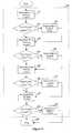
- FIG. 5is a Software System Overview flowchart
- FIG. 6is a System Initialisation and Maintenance Module flow chart
- FIG. 7is a flowchart depicting a macro view of Modulation Subroutine Modules, which includes four Modulation Subroutine Modules;
- FIG. 8is an Idle Time Handler Module flowchart
- FIG. 9is a flowchart of an Interrupt Service Routine that generates the pulse signal to energise the TRIACS means.
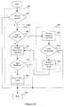
- FIG. 10is a Modulation Subroutine Module flowchart.
- a lighting controllerthat produces a wide variety of lighting displays characterised by synchronous and continuous modulated brightness of strings of lighting elements.
- the lighting controller controlsdelivers electrical power to strings of lighting elements using power sockets and performs brightness modulation of the strings of lighting elements through the power sockets.
- the brightness of decorative strings of lighting elementsmay be modulated to any level —independently increasing or decreasing at any rate or stopped at any point—to produce special lighting effects such as the emulation of a fireworks display.
- the lighting controllermay also enable a mixture of lighting colours to be produced by allowing different levels of colour intensities to be displayed for different strings of lighting elements with different lighting colours.
- the lighting controlleralso provides for low-rate modulation of light intensities thereby resulting in gradual transformation of lighting colours from one lighted string of lighting elements to the next lighted string of a different lighting colour.
- a number of lighting controllersmay interoperate to collectively act as a single entity.
- complicated wiring connectionsare not required for conveying synchronisation signals among multiple lighting controllers.
- group synchronisation of the lighting controllersis achieved through a common alternating-current (A/C) mains providing electricity supply from which the lighting controllers tap electricity.
- A/Calternating-current
- a micro-controlleris preferably used in the lighting controller according to embodiments of the invention, in which the modulation of light intensity of strings of lighting elements is performed by preferably using pulse signals generated directly by the micro-controller.
- the control logic of the lighting controlleris codified in software that is executed by the micro-controller while performing lighting control operations.
- the micro-controllerpreferably successively calculates and generates the pulse signals in every half period of an A/C cycle during the process of brightness modulation.
- the overall timing of the software-based lighting control operationsis preferably locked onto the A/C mains frequency. Since the A/C mains frequency is essentially a non-deviating frequency which is ubiquitous to all A/C sockets connected to the A/C mains, the lighting controllers that are connected to the A/C sockets are synchronised to the A/C mains frequency thereby exhibiting similar and predictable lighting control operations, which in this case is a similar pattern of lighting.
- a primary advantage of using the lighting controlleris that the lighting controller performs lighting control operations in a stand-alone mode as well as a synchronised-group mode.
- the lighting controllerperforms lighting control operations in a stand-alone mode as well as a synchronised-group mode.
- a number of lighting controllersmay synchronise as a group and lock onto the A/C mains frequency when the lighting controllers are connected to the common A/C mains and switched-on at the same time using a mains circuit breaker.
- no additional connection wiringis needed for a large number of lighting controllers to operate in the synchronised-group mode.
- a further advantage of using the lighting controlleris that the lighting controller modulates the light intensities of strings of lighting elements through a Modulation Subroutine Module (described in greater detail hereinafter) in the software.
- This software modulesuccessively calculates timing values and positions of pulse signals generated by the micro-controller with substantially precise timing relative to the zero crossing timing of the A/C mains to energise triacs for delivering power to strings of lighting elements. Changes in the calculated values of the timing for generating pulse signals eventually controls the ramp-up and ramp-down of power levels delivered through each triac, resulting in the modulation of the intensity of each string of lighting elements.
- the lighting controlleruses other software modules to load the various internal control parameters to the Modulation Subroutine Module to produce various brightness profiles and lighting effects in strings of lighting elements through the triacs.
- a still further advantage of using the lighting controlleris that the lighting controller utilises software to generate various sequencing controls to provide various sequences of lighting effects in which the sequencing controls only affect power sockets to which strings of lighting elements are connected.
- limited intelligenceis built into the lighting controller, so that in a practical situation where a user may not want to connect a string of lighting elements to every power socket, the lighting controller performs sequencing controls only according to the number of strings of lighting elements connected.
- the lighting sequencesare not disrupted because another string of lighting elements takes over.
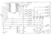
- a lighting controller printed circuit board(PCB) is located in a housing with A/C wiring ACin and a power plug PLU for connection to an A/C socket (not shown) to power the lighting controller and to deliver power to strings of lighting elements connected to a number of power sockets S 1 to S 4 .
- Triacs T 1 to T 4are used to switch A/C electricity supply to each power socket S 1 , S 2 , S 3 , or S 4 .
- the number of power sockets to be implementedis dependent on the number of triacs used and corresponding software modules used in lighting control operations.
- a power ON/OFF switch SWis connected in series with the A/C wiring ACin to allow a user to switch off the lighting controller when not in used.
- a fuse F 1is connected in series with the ON/OFF switch SW to provide short-circuit protection in the event of a short circuit in any connected string of lighting elements.
- An over-voltage protection device MOV 1 for suppressing any spikes in the A/C electricity supplyprovides additional protection for the triacs T 1 to T 4 .
- a capacitor C 1is used to supply an A/C electricity supply to a Zener diode D 1 with 5.6 volts rating.
- a 5.6 volts direct current (D/C) voltage developed across the Zener diode D 1then passes through a diode D 2 and charges up a capacitor C 2 to a D/C voltage of 5 volts.
- a 5 volts D/C supplyis thus formed across the terminals of the capacitor C 2 , a PCB reference ground GND being connected to one of the capacitor C 2 terminals, and is used to power a micro-controller U 1 .
- a capacitor C 3 placed in parallel with the capacitor C 2is used for filtering the 5 volts D/C supply by decoupling any A/C noise that is generated by the micro-controller U 1 .
- a resistor R 11is used to limit the charging current passing through the capacitor C 1 and a resistor R 12 is used to discharge any current remaining in the capacitor C 1 when the ON/OFF switch SW is open.
- a crystal XT 1is connected to the micro-controller U 1 for providing an oscillating frequency.
- the micro-controller U 1may be an embedded chip package of any form factor or bonded to the PCB.
- An example of a device that may be used as the micro-controller U 1is the PIC16F628 micro-controller from Microchip Technology, Inc.
- a resistor R 9is connected in series with the fuse F 1 and to reference pin PIN 2 of the micro-controller U 1 to convert the A/C electricity supply (50 Hertz or 60 Hertz) 201 as shown in FIG. 2 into a square wave 203 as shown in FIG. 3 .
- the square wave 203changes voltage levels so that the micro-controller U 1 may take reference from a leading edge 200 of each cycle of the A/C electricity supply.
- the substantially high resistance of resistor R 9 of several mega-ohmsprevents excessive current from the A/C electricity supply 201 from damaging the micro-controller U 1 .
- a pull-up resistor R 10connected between a reset pin PIN 4 of the micro-controller U 1 and the 5 volt supply and is used to drive the reset pin PIN 4 .
- Resistors R 1 , R 2 , R 3 , R 4are connected to detect pins PINl 3 , PIN 12 , PIN 11 , and PIN 10 , respectively, of the micro-controller U 1 to detect the presence of any string of lighting element, such as a string of decorative light bulbs, connected to any power socket S 1 , S 2 , S 3 , or S 4 , respectively.
- a signal 6 , 7 , 8 or 9 bearing the same waveform as the square wave 203may be present at any detect pin PIN 13 , PIN 12 , PIN 11 , or PIN 10 , thereby indicating that a string of lighting elements is connected to the corresponding power socket S 1 , S 2 , S 3 , or S 4 .
- the corresponding pin PIN 13 , PIN 12 , PIN 11 , or PIN 10remains floating with reference to the micro-controller U 1 ground pin PIN 5 , which is connected to the PCB reference ground GND.
- a software moduleprocesses the signals 6 , 7 , 8 or 9 to detect the presence or absence of a string of lighting elements at any power socket S 1 , S 2 , S 3 , or S 4 .
- Pulse signals 1 , 2 , 3 and 4are provided by pulse pins PIN 9 , PIN 8 , PIN 7 , and PIN 6 , respectively, and sent through respective series resistors R 5 , R 6 , R 7 and R 8 to trigger or actuate the triacs T 1 , T 2 , T 3 , and T 4 , respectively, to turn on and deliver the A/C electricity supply 201 to the respective power sockets S 1 , S 2 , S 3 , or S 4 .
- the triacs T 1 , T 2 , T 3 , and T 4turn off once the A/C electricity supply 201 reaches the next zero crossing point therefore cutting off the A/C electricity supply 201 to the power sockets S 1 , S 2 , S 3 , or S 4 .
- the pulse signals 1 , 2 , 3 and 4may be generated at any time within window periods 209 as shown in FIG. 4 . If a pulse signal 1 , 2 , 3 , or 4 is generated at the beginning of a window period 209 , the respective triac T 1 , T 2 , T 3 , or T 4 is turned on early in the window period 209 and therefore the light intensity of the respectively connected string of lighting elements is at the highest. Conversely, if a pulse signal 1 , 2 , 3 , or 4 is generated at near the end of a window period 209 , the light intensity of the respective connected string of lighting elements is at the lowest.
- the software codifying the control logic for the lighting controlleris a multi-process program. Hence, most of the codes are preferably reused for different processes of similar nature. For efficacy reasons, the description provided hereinafter with reference to FIGS. 5 to 10 thus only provides details of processes of different nature. Cross- or multi-process manipulations are also highlighted to show how different processes interact.
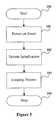
- the lighting controllerhereinafter referred to generally as the system, starts lighting control operations in process 100 upon power on. All hardware and software system resources are reset in a process 101 to a fix value.
- the systeminitialises in a process 102 all micro-controller U 1 resources, for example Reset Vectors, Interrupt Service Routine Vectors, and etc., to begin program execution. After which, the program runs by looping infinitely in a process 103 until the power is switch off, where the system terminates lighting control operations immediately in a process 104 .
- the program executionis explained in terms of processes hereinafter and all different processes are mutually exclusive in terms of system resources, for example, memory locations and registers, and time of execution.
- There are four main variables in the programnamely Pulse Position, Pulse Position Counter, Ramp Rate and Ramp Value with Sign Bit. These variables are private, in terms of uniqueness, to corresponding processes.
- Nnumber of processes
- the programmay be scaled to include more processes to control additional triacs to deliver electricity supply to additional power sockets.
- programrefers to all the various processes as one entity.
- modulerefers to the conceptual embodiment of a process.
- the looping process 103is described hereinafter to explain how the program through the different processes interacts with the hardware in the system to produce the electrical effects resulting in the generation of pulse signals shown in FIG. 4 .
- the looping process 103includes various subroutine modules 106 (FIG. 6 ), 122 (FIG. 8 ), 130 (FIG. 9 ), 144 , 146 and 151 (FIG. 10 ).
- the looping process 103also includes a subroutine module 116 (FIG. 7 ), which is an exception since the subroutine module 116 includes four unique processes that share a same source code and is therefore strictly not a subroutine module.
- the subroutine module 106is known as a System Initialisation and Maintenance Module. The purpose of this subroutine module is to set up and maintain operating parameters and variables for subsequent subroutines.
- the System Initialisation and Maintenance Moduleare known as a System Initialisation and Maintenance Module.
- Maintenance Moduleis also the subroutine responsible for manipulating the variables so that various effects, the parameters of which are stored in micro-controller U 1 memory, may manifest through progressive looping.
- the parametersstore the amount of changes that need to be added or subtracted from the variables so that the ramping-up or -down effects may be observed.
- a large parameter valuesignifies a large amount of change in brightness and a small parameter is observable as a very gradual change in brightness.
- the subroutine module 116known as Modulation Subroutine Modules is executed.
- the subroutine module 116known as Modulation Subroutine Modules is executed.
- four triacs T 1 to T 4are used for delivering electricity supply to the power sockets S 1 to S 4 . Therefore, four processes 117 , 118 , 119 , and 120 are executed in the Modulation Subroutine Module regardless of the number of power socket S 1 to S 4 that are connected to strings of lighted elements.
- the Modulation Subroutine Modulesbasically determine at which point and through which pulse pin PIN 9 , PIN 8 , PIN 7 , or P 1 N 6 to send a pulse signal 1 , 2 , 3 , or 4 , respectively, to trigger or fire the corresponding triac T 1 , T 2 , T 3 , or T 4 .
- the Modulation Subroutine Modulesdo not cause the pulse signals 1 , 2 , 3 , and 4 to fire but calculate values known as Pulse Positions for generating the pulse signals 1 , 2 , 3 , and 4 and store the values in variables.
- the Modulation Subroutine Modulesare also synchronised to the zero crossing points 202 so that all other lighting controllers executing the same program may create exactly the same lighting effect.
- the Modulation Subroutine Moduleis executed four times for the four power sockets S 1 to S 4 after which the program waits for the next zero crossing point 202 in an Idle Time Handler Module 122 as shown in FIG. 7 .
- an Interrupt signaltriggers the micro-controller U 1 to execute an Interrupt Service Routine Module 130 .
- the variables calculated in the Modulation Subroutine Modulesare used to trigger the triacs T 1 to T 4 .
- a corresponding triac T 1 , T 2 , T 3 , or T 4may receive the pulse signal 1 , 2 , 3 , or 4 , respectively, at the appropriate moment so as to generate the correct amount of electricity current for a smooth modulation of light brightness.
- the System Initialisation and Maintenance Module 106starts execution in a step 105 .
- the primary function of the System Initialisation and Maintenance Module 106is to re-initialise the looping process 103 at every zero crossing point 202 with the effect of group-synchronisation in situations where multiple lighting controllers are used, and perform maintenance functions including time delay for pattern sequencing.
- a first step 107 during the execution of the System Initialisation and Maintenance Module 106is the disabling of the micro-controller U 1 Interrupt Handler so that no external signals can interrupt the looping process 103 during the crucial phase when maintenance subroutines are executed in the looping process 103 .
- step 108to update values known as Pulse Position Counters by copying the Pulse Positions values.
- the looping process 103then enables the micro-controller U 1 Interrupt Handler in step 109 to allow an internal timer signal to trigger the Interrupt Service Routine Module 130 .
- the current processcontinues in a step 110 with performing various Miscellaneous Timing Management Routines to ensure synchronised execution of the various processes.
- the current processthen checks the status of the power sockets S 1 to S 4 in step 111 by polling the power sockets S 1 to S 4 for the square wave signal 6 , 7 , 8 , or 9 . If a square wave signal 6 , 7 , 8 , or 9 of the same frequency with the A/C mains is detected, the corresponding power socket S 1 , S 2 , S 3 , or S 4 is connected and is marked as active. If a signal bearing a waveform other than a square wave is detected, the corresponding power socket S 1 , S 2 , S 3 , or S 4 is not connected, and is marked as inactive. In both cases, a status variable is updated to reflect the appropriate state of the power socket S 1 , S 2 , S 3 , or S 4 .
- the current processcontinues by dynamically assigning various Modulation Subroutine Modules to different output power sockets S 1 to S 4 in a step 112 .
- the assignmentmay be randomly determined or pre-loaded from a special profile. The effect of this is that different strings of lights with different colours exhibit various different patterns of lighting effects at different time.
- the current processinitialises a Sequence Control event in a step 113 , which controls the pattern generation based on a multitude of effect patterns that are pre-loaded. These effect patterns allow the display of various effects such as fireworks, gentle wave, etc.
- the Sequence Control eventaccomplishes the effects patterns by setting certain parameters in the step 113 so that a Monitor Sequence Progress event occurring in a step 114 may handle the actual execution of the effect pattern.
- the effects patternsconsist of various parameters that are organised in groups of steps. These groups form effects patterns that may be created or modified by a producer.
- the Monitor Sequence Progress event in the step 114monitors the groups assigned to the various modules and track the steps that have been executed. When the steps have been executed, a new group of effects patterns is assigned to another module for execution.
- the looping process 103exits the System Initialisation and Maintenance Module in a step 115 and proceeds to the Modulation Subroutine Modules 116 (MSRs).
- MSRsModulation Subroutine Modules
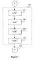
- the Modulation Subroutine Modules 116are described in greater detail to illustrate the relationship between the different processes designated MSR 1 117 through MSR 4 120 .
- the processes MSR 1 117 through MSR 4 120essentially rely on execution of the same source code, the only difference being the parameters loaded into each Modulation Subroutine Module.
- the different processesare executed in sequence 117 , 118 , 119 , 120 , before the looping process 103 proceeds in a step 121 to the Idle Time Handler Module 122 .
- the looping process 103enters the Idle Time Handler Module 122 in the step 121 . Since the micro-controller operates at a much faster rate than half an A/C cycle, a long period of idle time passes during a wait event in a step 123 before the next zero crossing point 202 is reached.
- the current processchecks for a zero crossing point 202 in a step 124 . If a zero crossing point 202 detected, the micro-controller Interrupt Handler is disabled in a step 125 so the current process exits in a step 126 and returns in a step 156 to update the next Pulse Position Counters in the step 108 . Otherwise, the current process loops back to the step 123 .
- the ISR 130is a special subroutine module because the ISR 130 may be executed at any time regardless of at which point the program is executing, except when the microcontroller U 1 Interrupt Handler is disabled.
- ISR 130is executed, the program is halted and program states including registers and stacks pointers are saved. The micro-controller U 1 then loads the ISR 130 and begins execution.
- the ISR 130is used when a critical real-time function needs to be executed without delay, such as the generation of a pulse signal 1 , 2 , 3 , or 4 to fire a triac T 1 , T 2 , T 3 , or T 4 .
- the ISR 130After the program is halted, the ISR 130 first decrements a Pulse Position Counter associated with the MSR 1 117 in a step 131 and checks if the Pulse Position Counter is equal to zero in a step 132 . If the Pulse Position Counter is zero, a pulse signal 1 , 2 , 3 , or 4 in a step 139 is sent to trigger the triac T 1 , T 2 , T 3 , or T 4 of the assigned power socket S 1 , S 2 , S 3 , or S 4 . The pre-determined information is store in an Output Socket Index. After firing, the current process continues by decrementing the Pulse Position Counter of the next Modulation Subroutine Module.
- the Pulse Position Counter of the MSR 1 117is not zero in the step 132 , the Pulse Position Counter of the next Modulation Subroutine Module is also decremented. This process is continued for all three remaining Modulation Subroutine Modules.
- the ISR 130goes though a similar sequence of Pulse Position Counter decrement in a step 133 , zero checking in a step 134 and triac firing in a step 140 in relation to the next Modulation Subroutine Module.
- the ISR 130undergoes another similar sequence of steps 135 , 136 , 141 for the next Modulation Subroutine Module, and a further similar sequence of steps 137 , 138 , 142 for the last Modulation Subroutine Module. Following which, the current process exits in a step 143 and the micro-controller U 1 restores the previous program state and continue running from that point onwards.
- the looping process 103enters the Modulation Subroutine Module in a process 144 , the main purpose of which is to calculate the value for the firing of a pulse signal 1 , 2 , 3 , or 4 that triggers a triac T 1 , T 2 , T 3 , or T 4 .
- the calculated valueis called Pulse Position. Since the Modulation Subroutine Module is executed at every zero crossing point of each A/C cycle, the Pulse Position value may be updated on every execution. This is, however, subject to a Ramp Rate value, which is a preloaded parameter used in the current process. If the Ramp Rate value is ‘1’, the updating is done on every execution. If the Ramp Rate value is ‘N’, then out of every N executions, only one update is done.
- the current process in the step 145checks if the Pulse Position value is due for update. If not, the current process exits in a step 155 . If update is due, the looping process 103 enters a process 146 and checks from a Ramp Value, which is a parameter used in the current process, whether the channel is on a ramp up cycle or ramp down cycle in a step 147 .
- the looping process 103When the current process detects that the channel is on a ramp up cycle, the looping process 103 enters a process 151 and performs ramp up operation in a step 152 by reducing the Pulse Position value by an amount specified in the Ramp Value. The current process then checks the Pulse Position value for the maximum brightness value in a step 153 . If maximum brightness is not reached, the current process exits in the step 155 . If maximum brightness is reached, the channel is reset to ramp down cycle in a step 154 and the looping process 103 returns to a step 148 to perform ramp down operations.
- the current processWhen the current process detects that the Modulation Subroutine Module is on a ramp down cycle in the step 147 , the current process performs the ramp down operations in the step 148 by increasing the Pulse Position by the amount specified in the Ramp Value. The current process then checks the Pulse Position value for the minimum brightness value. If minimum brightness is not reached, the current process exits in the step 155 . If minimum brightness is reached or surpassed, the Pulse Position value is reset to the minimum value in a step 150 to prevent an overflow condition and the current process exits in the step 155 .
- a lighting controlleris described according to embodiments of the invention for providing a wide variety of lighting displays characterised by synchronous and continuous modulated brightness of strings of lighting elements.
Landscapes
- Engineering & Computer Science (AREA)
- Power Engineering (AREA)
- Circuit Arrangement For Electric Light Sources In General (AREA)
Abstract
Description
Claims (10)
Priority Applications (1)
| Application Number | Priority Date | Filing Date | Title |
|---|---|---|---|
| US09/811,984US6384545B1 (en) | 2001-03-19 | 2001-03-19 | Lighting controller |
Applications Claiming Priority (1)
| Application Number | Priority Date | Filing Date | Title |
|---|---|---|---|
| US09/811,984US6384545B1 (en) | 2001-03-19 | 2001-03-19 | Lighting controller |
Publications (1)
| Publication Number | Publication Date |
|---|---|
| US6384545B1true US6384545B1 (en) | 2002-05-07 |
Family
ID=25208140
Family Applications (1)
| Application Number | Title | Priority Date | Filing Date |
|---|---|---|---|
| US09/811,984Expired - LifetimeUS6384545B1 (en) | 2001-03-19 | 2001-03-19 | Lighting controller |
Country Status (1)
| Country | Link |
|---|---|
| US (1) | US6384545B1 (en) |
Cited By (78)
| Publication number | Priority date | Publication date | Assignee | Title |
|---|---|---|---|---|
| US6690120B2 (en) | 2002-05-10 | 2004-02-10 | Frank Joseph Oskorep | Year-round decorative lights with selectable holiday color schemes |
| WO2003105540A3 (en)* | 2002-06-05 | 2004-03-11 | Anytronics Ltd | Lighting control apparatus |
| US20040066148A1 (en)* | 2002-05-10 | 2004-04-08 | Oskorep Frank Joseph | Decorative lights with at least one commonly controlled set of color-controllable multi-color LEDs for selectable holiday color schemes |
| EP1411753A1 (en)* | 2002-10-07 | 2004-04-21 | Teknoware Oy | Arrangement for lighting fixtures |
| US20040150994A1 (en)* | 2002-10-03 | 2004-08-05 | Kazar Dennis Michael | Year-round decorative lights with addressable color-controllable led nodes for selectable holiday color schemes |
| US20050122718A1 (en)* | 2002-05-10 | 2005-06-09 | Kazar Dennis M. | Year-round decorative lights with multiple strings of series-coupled bipolar bicolor leds for selectable holiday color schemes |
| US20050162851A1 (en)* | 2004-01-23 | 2005-07-28 | Kazar Dennis M. | Year-round decorative lights with time-multiplexed illumination of interleaved sets of color-controllable leds |
| US20050168983A1 (en)* | 2002-05-10 | 2005-08-04 | Oskorep Frank J. | Year-round decorative lights with selectable holiday color schemes and associated methods |
| US7301290B1 (en)* | 2007-02-23 | 2007-11-27 | Ming-Chi Tseng | Brightness control device of light bulb module |
| US20090238252A1 (en)* | 2008-03-20 | 2009-09-24 | Ashok Deepak Shah | Managing SSL Fixtures Over PLC Networks |
| US20100061734A1 (en)* | 2008-09-05 | 2010-03-11 | Knapp David J | Optical communication device, method and system |
| US20100188972A1 (en)* | 2009-01-27 | 2010-07-29 | Knapp David J | Fault tolerant network utilizing bi-directional point-to-point communications links between nodes |
| US20100327764A1 (en)* | 2008-09-05 | 2010-12-30 | Knapp David J | Intelligent illumination device |
| US20110069960A1 (en)* | 2008-09-05 | 2011-03-24 | Knapp David J | Systems and methods for visible light communication |
| US8070325B2 (en) | 2006-04-24 | 2011-12-06 | Integrated Illumination Systems | LED light fixture |
| US8243278B2 (en) | 2008-05-16 | 2012-08-14 | Integrated Illumination Systems, Inc. | Non-contact selection and control of lighting devices |
| US8262243B1 (en) | 2012-05-11 | 2012-09-11 | Pasdar Mohammad B | Christmas ornament with selectable illumination and motion mechanisms |
| US8278845B1 (en) | 2011-07-26 | 2012-10-02 | Hunter Industries, Inc. | Systems and methods for providing power and data to lighting devices |
| US8436553B2 (en) | 2007-01-26 | 2013-05-07 | Integrated Illumination Systems, Inc. | Tri-light |
| US8436549B2 (en) | 2010-08-13 | 2013-05-07 | Bridgelux, Inc. | Drive circuit for a color temperature tunable LED light source |
| US8456092B2 (en) | 2008-09-05 | 2013-06-04 | Ketra, Inc. | Broad spectrum light source calibration systems and related methods |
| US8469542B2 (en) | 2004-05-18 | 2013-06-25 | II Thomas L. Zampini | Collimating and controlling light produced by light emitting diodes |
| US8471496B2 (en) | 2008-09-05 | 2013-06-25 | Ketra, Inc. | LED calibration systems and related methods |
| US8567982B2 (en) | 2006-11-17 | 2013-10-29 | Integrated Illumination Systems, Inc. | Systems and methods of using a lighting system to enhance brand recognition |
| US8585245B2 (en) | 2009-04-23 | 2013-11-19 | Integrated Illumination Systems, Inc. | Systems and methods for sealing a lighting fixture |
| US8674913B2 (en) | 2008-09-05 | 2014-03-18 | Ketra, Inc. | LED transceiver front end circuitry and related methods |
| US8742686B2 (en) | 2007-09-24 | 2014-06-03 | Integrated Illumination Systems, Inc. | Systems and methods for providing an OEM level networked lighting system |
| US8749172B2 (en) | 2011-07-08 | 2014-06-10 | Ketra, Inc. | Luminance control for illumination devices |
| US8773336B2 (en) | 2008-09-05 | 2014-07-08 | Ketra, Inc. | Illumination devices and related systems and methods |
| US8894437B2 (en) | 2012-07-19 | 2014-11-25 | Integrated Illumination Systems, Inc. | Systems and methods for connector enabling vertical removal |
| US8915609B1 (en) | 2008-03-20 | 2014-12-23 | Cooper Technologies Company | Systems, methods, and devices for providing a track light and portable light |
| US9066381B2 (en) | 2011-03-16 | 2015-06-23 | Integrated Illumination Systems, Inc. | System and method for low level dimming |
| US9146028B2 (en) | 2013-12-05 | 2015-09-29 | Ketra, Inc. | Linear LED illumination device with improved rotational hinge |
| US9155155B1 (en) | 2013-08-20 | 2015-10-06 | Ketra, Inc. | Overlapping measurement sequences for interference-resistant compensation in light emitting diode devices |
| US9237623B1 (en) | 2015-01-26 | 2016-01-12 | Ketra, Inc. | Illumination device and method for determining a maximum lumens that can be safely produced by the illumination device to achieve a target chromaticity |
| US9237620B1 (en) | 2013-08-20 | 2016-01-12 | Ketra, Inc. | Illumination device and temperature compensation method |
| US9237612B1 (en) | 2015-01-26 | 2016-01-12 | Ketra, Inc. | Illumination device and method for determining a target lumens that can be safely produced by an illumination device at a present temperature |
| US9247605B1 (en) | 2013-08-20 | 2016-01-26 | Ketra, Inc. | Interference-resistant compensation for illumination devices |
| US9276766B2 (en) | 2008-09-05 | 2016-03-01 | Ketra, Inc. | Display calibration systems and related methods |
| RU2581048C1 (en)* | 2013-10-15 | 2016-04-10 | Мицубиси Электрик Корпорейшн | Light source control device and light source control method |
| US9332598B1 (en) | 2013-08-20 | 2016-05-03 | Ketra, Inc. | Interference-resistant compensation for illumination devices having multiple emitter modules |
| US9345097B1 (en) | 2013-08-20 | 2016-05-17 | Ketra, Inc. | Interference-resistant compensation for illumination devices using multiple series of measurement intervals |
| US9360174B2 (en) | 2013-12-05 | 2016-06-07 | Ketra, Inc. | Linear LED illumination device with improved color mixing |
| US9379578B2 (en) | 2012-11-19 | 2016-06-28 | Integrated Illumination Systems, Inc. | Systems and methods for multi-state power management |
| US9386668B2 (en) | 2010-09-30 | 2016-07-05 | Ketra, Inc. | Lighting control system |
| US9392660B2 (en) | 2014-08-28 | 2016-07-12 | Ketra, Inc. | LED illumination device and calibration method for accurately characterizing the emission LEDs and photodetector(s) included within the LED illumination device |
| US9392663B2 (en) | 2014-06-25 | 2016-07-12 | Ketra, Inc. | Illumination device and method for controlling an illumination device over changes in drive current and temperature |
| US9420665B2 (en) | 2012-12-28 | 2016-08-16 | Integration Illumination Systems, Inc. | Systems and methods for continuous adjustment of reference signal to control chip |
| US9485814B2 (en) | 2013-01-04 | 2016-11-01 | Integrated Illumination Systems, Inc. | Systems and methods for a hysteresis based driver using a LED as a voltage reference |
| US9485813B1 (en) | 2015-01-26 | 2016-11-01 | Ketra, Inc. | Illumination device and method for avoiding an over-power or over-current condition in a power converter |
| US9510416B2 (en) | 2014-08-28 | 2016-11-29 | Ketra, Inc. | LED illumination device and method for accurately controlling the intensity and color point of the illumination device over time |
| US9521725B2 (en) | 2011-07-26 | 2016-12-13 | Hunter Industries, Inc. | Systems and methods for providing power and data to lighting devices |
| US9557214B2 (en) | 2014-06-25 | 2017-01-31 | Ketra, Inc. | Illumination device and method for calibrating an illumination device over changes in temperature, drive current, and time |
| US9578724B1 (en) | 2013-08-20 | 2017-02-21 | Ketra, Inc. | Illumination device and method for avoiding flicker |
| US9609720B2 (en) | 2011-07-26 | 2017-03-28 | Hunter Industries, Inc. | Systems and methods for providing power and data to lighting devices |
| US9651632B1 (en) | 2013-08-20 | 2017-05-16 | Ketra, Inc. | Illumination device and temperature calibration method |
| US9736903B2 (en) | 2014-06-25 | 2017-08-15 | Ketra, Inc. | Illumination device and method for calibrating and controlling an illumination device comprising a phosphor converted LED |
| US9736895B1 (en) | 2013-10-03 | 2017-08-15 | Ketra, Inc. | Color mixing optics for LED illumination device |
| US9769899B2 (en) | 2014-06-25 | 2017-09-19 | Ketra, Inc. | Illumination device and age compensation method |
| US9967940B2 (en) | 2011-05-05 | 2018-05-08 | Integrated Illumination Systems, Inc. | Systems and methods for active thermal management |
| US10030844B2 (en) | 2015-05-29 | 2018-07-24 | Integrated Illumination Systems, Inc. | Systems, methods and apparatus for illumination using asymmetrical optics |
| US10060599B2 (en) | 2015-05-29 | 2018-08-28 | Integrated Illumination Systems, Inc. | Systems, methods and apparatus for programmable light fixtures |
| US10159132B2 (en) | 2011-07-26 | 2018-12-18 | Hunter Industries, Inc. | Lighting system color control |
| US10161786B2 (en) | 2014-06-25 | 2018-12-25 | Lutron Ketra, Llc | Emitter module for an LED illumination device |
| US10210750B2 (en) | 2011-09-13 | 2019-02-19 | Lutron Electronics Co., Inc. | System and method of extending the communication range in a visible light communication system |
| US10228711B2 (en) | 2015-05-26 | 2019-03-12 | Hunter Industries, Inc. | Decoder systems and methods for irrigation control |
| US10801714B1 (en) | 2019-10-03 | 2020-10-13 | CarJamz, Inc. | Lighting device |
| US10874003B2 (en) | 2011-07-26 | 2020-12-22 | Hunter Industries, Inc. | Systems and methods for providing power and data to devices |
| US10918030B2 (en) | 2015-05-26 | 2021-02-16 | Hunter Industries, Inc. | Decoder systems and methods for irrigation control |
| USRE48955E1 (en) | 2013-08-20 | 2022-03-01 | Lutron Technology Company Llc | Interference-resistant compensation for illumination devices having multiple emitter modules |
| USRE48956E1 (en) | 2013-08-20 | 2022-03-01 | Lutron Technology Company Llc | Interference-resistant compensation for illumination devices using multiple series of measurement intervals |
| US11272599B1 (en) | 2018-06-22 | 2022-03-08 | Lutron Technology Company Llc | Calibration procedure for a light-emitting diode light source |
| USRE49454E1 (en) | 2010-09-30 | 2023-03-07 | Lutron Technology Company Llc | Lighting control system |
| RU2804930C1 (en)* | 2023-03-22 | 2023-10-09 | Общество с ограниченной ответственностью "ЭНЕРГО-АРСЕНАЛ" | Lighting control system |
| US11917740B2 (en) | 2011-07-26 | 2024-02-27 | Hunter Industries, Inc. | Systems and methods for providing power and data to devices |
| US12297996B2 (en) | 2023-02-16 | 2025-05-13 | Integrated Illumination Systems, Inc. | Cove light fixture with hidden integrated air return |
| USRE50468E1 (en) | 2008-09-05 | 2025-06-24 | Lutron Technology Company Llc | Intelligent illumination device |
| US12416908B2 (en) | 2022-12-29 | 2025-09-16 | Integrated Illumination Systems, Inc. | Systems and methods for manufacturing light fixtures |
Citations (9)
| Publication number | Priority date | Publication date | Assignee | Title |
|---|---|---|---|---|
| US4125781A (en) | 1975-12-02 | 1978-11-14 | Davis George B Jun | Christmas tree lighting control |
| US4215277A (en)* | 1979-02-09 | 1980-07-29 | Robert I. Weiner | Sequencing light controller |
| US4253045A (en)* | 1979-02-12 | 1981-02-24 | Weber Harold J | Flickering flame effect electric light controller |
| US4678926A (en) | 1986-02-05 | 1987-07-07 | Davis George B | Christmas tree lighting control |
| US4890000A (en) | 1988-10-13 | 1989-12-26 | George Chou | Control circuit of the decorative light sets |
| US5128595A (en)* | 1990-10-23 | 1992-07-07 | Minami International Corporation | Fader for miniature lights |
| US5300864A (en)* | 1992-10-06 | 1994-04-05 | Almic Industries | Programmable lighting control system |
| US5629587A (en)* | 1995-09-26 | 1997-05-13 | Devtek Development Corporation | Programmable lighting control system for controlling illumination duration and intensity levels of lamps in multiple lighting strings |
| US6285140B1 (en)* | 1999-04-21 | 2001-09-04 | Pharos Innovations Inc. | Variable-effect lighting system |
- 2001
- 2001-03-19USUS09/811,984patent/US6384545B1/ennot_activeExpired - Lifetime
Patent Citations (9)
| Publication number | Priority date | Publication date | Assignee | Title |
|---|---|---|---|---|
| US4125781A (en) | 1975-12-02 | 1978-11-14 | Davis George B Jun | Christmas tree lighting control |
| US4215277A (en)* | 1979-02-09 | 1980-07-29 | Robert I. Weiner | Sequencing light controller |
| US4253045A (en)* | 1979-02-12 | 1981-02-24 | Weber Harold J | Flickering flame effect electric light controller |
| US4678926A (en) | 1986-02-05 | 1987-07-07 | Davis George B | Christmas tree lighting control |
| US4890000A (en) | 1988-10-13 | 1989-12-26 | George Chou | Control circuit of the decorative light sets |
| US5128595A (en)* | 1990-10-23 | 1992-07-07 | Minami International Corporation | Fader for miniature lights |
| US5300864A (en)* | 1992-10-06 | 1994-04-05 | Almic Industries | Programmable lighting control system |
| US5629587A (en)* | 1995-09-26 | 1997-05-13 | Devtek Development Corporation | Programmable lighting control system for controlling illumination duration and intensity levels of lamps in multiple lighting strings |
| US6285140B1 (en)* | 1999-04-21 | 2001-09-04 | Pharos Innovations Inc. | Variable-effect lighting system |
Cited By (139)
| Publication number | Priority date | Publication date | Assignee | Title |
|---|---|---|---|---|
| US7102301B2 (en) | 2002-05-10 | 2006-09-05 | Frank Joseph Oskorep | Year-round decorative lights with selectable holiday color schemes |
| US6933680B2 (en) | 2002-05-10 | 2005-08-23 | Frank Joseph Oskorep | Decorative lights with at least one commonly controlled set of color-controllable multi-color LEDs for selectable holiday color schemes |
| US20040066148A1 (en)* | 2002-05-10 | 2004-04-08 | Oskorep Frank Joseph | Decorative lights with at least one commonly controlled set of color-controllable multi-color LEDs for selectable holiday color schemes |
| US20080185973A1 (en)* | 2002-05-10 | 2008-08-07 | Year-Round Creations, Llc | Year-Round Decorative Lights With Selectable Color Schemes And Associated Methods |
| US7175302B2 (en) | 2002-05-10 | 2007-02-13 | Year-Round Creations, Llc | Year-round decorative lights with multiple strings of series-coupled bipolar bicolor LEDs for selectable holiday color schemes |
| US20040119421A1 (en)* | 2002-05-10 | 2004-06-24 | Oskorep Frank Joseph | Year-round decorative lights with selectable holiday color schemes |
| US7257551B2 (en) | 2002-05-10 | 2007-08-14 | Year-Round Creations, Llc | Year-round decorative lights with selectable holiday color schemes and associated methods |
| US20050168983A1 (en)* | 2002-05-10 | 2005-08-04 | Oskorep Frank J. | Year-round decorative lights with selectable holiday color schemes and associated methods |
| US6690120B2 (en) | 2002-05-10 | 2004-02-10 | Frank Joseph Oskorep | Year-round decorative lights with selectable holiday color schemes |
| US20050122718A1 (en)* | 2002-05-10 | 2005-06-09 | Kazar Dennis M. | Year-round decorative lights with multiple strings of series-coupled bipolar bicolor leds for selectable holiday color schemes |
| GB2392020B (en)* | 2002-06-05 | 2005-12-28 | Anytronics Ltd | Lighting control apparatus |
| WO2003105540A3 (en)* | 2002-06-05 | 2004-03-11 | Anytronics Ltd | Lighting control apparatus |
| US20040150994A1 (en)* | 2002-10-03 | 2004-08-05 | Kazar Dennis Michael | Year-round decorative lights with addressable color-controllable led nodes for selectable holiday color schemes |
| US7131748B2 (en) | 2002-10-03 | 2006-11-07 | Year-Round Creations, Llc | Decorative lights with addressable color-controllable LED nodes and control circuitry, and method |
| US20040108820A1 (en)* | 2002-10-07 | 2004-06-10 | Teknoware Oy | Arrangement for lighting fixture |
| EP1411753A1 (en)* | 2002-10-07 | 2004-04-21 | Teknoware Oy | Arrangement for lighting fixtures |
| US20050162851A1 (en)* | 2004-01-23 | 2005-07-28 | Kazar Dennis M. | Year-round decorative lights with time-multiplexed illumination of interleaved sets of color-controllable leds |
| US7202607B2 (en) | 2004-01-23 | 2007-04-10 | Year-Round Creations, Llc | Year-round decorative lights with time-multiplexed illumination of interleaved sets of color-controllable LEDS |
| US8469542B2 (en) | 2004-05-18 | 2013-06-25 | II Thomas L. Zampini | Collimating and controlling light produced by light emitting diodes |
| US8070325B2 (en) | 2006-04-24 | 2011-12-06 | Integrated Illumination Systems | LED light fixture |
| US8567982B2 (en) | 2006-11-17 | 2013-10-29 | Integrated Illumination Systems, Inc. | Systems and methods of using a lighting system to enhance brand recognition |
| US8436553B2 (en) | 2007-01-26 | 2013-05-07 | Integrated Illumination Systems, Inc. | Tri-light |
| US7301290B1 (en)* | 2007-02-23 | 2007-11-27 | Ming-Chi Tseng | Brightness control device of light bulb module |
| US8742686B2 (en) | 2007-09-24 | 2014-06-03 | Integrated Illumination Systems, Inc. | Systems and methods for providing an OEM level networked lighting system |
| US8466585B2 (en) | 2008-03-20 | 2013-06-18 | Cooper Technologies Company | Managing SSL fixtures over PLC networks |
| US8915609B1 (en) | 2008-03-20 | 2014-12-23 | Cooper Technologies Company | Systems, methods, and devices for providing a track light and portable light |
| US8148854B2 (en) | 2008-03-20 | 2012-04-03 | Cooper Technologies Company | Managing SSL fixtures over PLC networks |
| US10645770B2 (en) | 2008-03-20 | 2020-05-05 | Signify Holding B.V. | Energy management system |
| US8543226B2 (en) | 2008-03-20 | 2013-09-24 | Cooper Technologies Company | Energy management system |
| US9591724B2 (en) | 2008-03-20 | 2017-03-07 | Cooper Technologies Company | Managing SSL fixtures over PLC networks |
| US20090240380A1 (en)* | 2008-03-20 | 2009-09-24 | Ashok Deepak Shah | Energy management system |
| US20090238252A1 (en)* | 2008-03-20 | 2009-09-24 | Ashok Deepak Shah | Managing SSL Fixtures Over PLC Networks |
| US8243278B2 (en) | 2008-05-16 | 2012-08-14 | Integrated Illumination Systems, Inc. | Non-contact selection and control of lighting devices |
| US8255487B2 (en) | 2008-05-16 | 2012-08-28 | Integrated Illumination Systems, Inc. | Systems and methods for communicating in a lighting network |
| US8264172B2 (en) | 2008-05-16 | 2012-09-11 | Integrated Illumination Systems, Inc. | Cooperative communications with multiple master/slaves in a LED lighting network |
| US8471496B2 (en) | 2008-09-05 | 2013-06-25 | Ketra, Inc. | LED calibration systems and related methods |
| USRE50468E1 (en) | 2008-09-05 | 2025-06-24 | Lutron Technology Company Llc | Intelligent illumination device |
| US9295112B2 (en) | 2008-09-05 | 2016-03-22 | Ketra, Inc. | Illumination devices and related systems and methods |
| US10847026B2 (en) | 2008-09-05 | 2020-11-24 | Lutron Ketra, Llc | Visible light communication system and method |
| US8521035B2 (en) | 2008-09-05 | 2013-08-27 | Ketra, Inc. | Systems and methods for visible light communication |
| US9509525B2 (en) | 2008-09-05 | 2016-11-29 | Ketra, Inc. | Intelligent illumination device |
| US9276766B2 (en) | 2008-09-05 | 2016-03-01 | Ketra, Inc. | Display calibration systems and related methods |
| US20100327764A1 (en)* | 2008-09-05 | 2010-12-30 | Knapp David J | Intelligent illumination device |
| US8674913B2 (en) | 2008-09-05 | 2014-03-18 | Ketra, Inc. | LED transceiver front end circuitry and related methods |
| US20100061734A1 (en)* | 2008-09-05 | 2010-03-11 | Knapp David J | Optical communication device, method and system |
| US20110069960A1 (en)* | 2008-09-05 | 2011-03-24 | Knapp David J | Systems and methods for visible light communication |
| US8456092B2 (en) | 2008-09-05 | 2013-06-04 | Ketra, Inc. | Broad spectrum light source calibration systems and related methods |
| US8773336B2 (en) | 2008-09-05 | 2014-07-08 | Ketra, Inc. | Illumination devices and related systems and methods |
| US8886047B2 (en) | 2008-09-05 | 2014-11-11 | Ketra, Inc. | Optical communication device, method and system |
| US8179787B2 (en) | 2009-01-27 | 2012-05-15 | Smsc Holding S.A.R.L. | Fault tolerant network utilizing bi-directional point-to-point communications links between nodes |
| US20100188972A1 (en)* | 2009-01-27 | 2010-07-29 | Knapp David J | Fault tolerant network utilizing bi-directional point-to-point communications links between nodes |
| US8585245B2 (en) | 2009-04-23 | 2013-11-19 | Integrated Illumination Systems, Inc. | Systems and methods for sealing a lighting fixture |
| US8436549B2 (en) | 2010-08-13 | 2013-05-07 | Bridgelux, Inc. | Drive circuit for a color temperature tunable LED light source |
| US9386668B2 (en) | 2010-09-30 | 2016-07-05 | Ketra, Inc. | Lighting control system |
| USRE49454E1 (en) | 2010-09-30 | 2023-03-07 | Lutron Technology Company Llc | Lighting control system |
| US9066381B2 (en) | 2011-03-16 | 2015-06-23 | Integrated Illumination Systems, Inc. | System and method for low level dimming |
| US9967940B2 (en) | 2011-05-05 | 2018-05-08 | Integrated Illumination Systems, Inc. | Systems and methods for active thermal management |
| US8749172B2 (en) | 2011-07-08 | 2014-06-10 | Ketra, Inc. | Luminance control for illumination devices |
| US10159132B2 (en) | 2011-07-26 | 2018-12-18 | Hunter Industries, Inc. | Lighting system color control |
| US10375793B2 (en) | 2011-07-26 | 2019-08-06 | Hunter Industries, Inc. | Systems and methods for providing power and data to devices |
| US10874003B2 (en) | 2011-07-26 | 2020-12-22 | Hunter Industries, Inc. | Systems and methods for providing power and data to devices |
| US12302474B2 (en) | 2011-07-26 | 2025-05-13 | Hunter Industries, Inc. | Systems and methods for providing power and data to devices |
| US9609720B2 (en) | 2011-07-26 | 2017-03-28 | Hunter Industries, Inc. | Systems and methods for providing power and data to lighting devices |
| US9521725B2 (en) | 2011-07-26 | 2016-12-13 | Hunter Industries, Inc. | Systems and methods for providing power and data to lighting devices |
| US11917740B2 (en) | 2011-07-26 | 2024-02-27 | Hunter Industries, Inc. | Systems and methods for providing power and data to devices |
| US8278845B1 (en) | 2011-07-26 | 2012-10-02 | Hunter Industries, Inc. | Systems and methods for providing power and data to lighting devices |
| US8710770B2 (en) | 2011-07-26 | 2014-04-29 | Hunter Industries, Inc. | Systems and methods for providing power and data to lighting devices |
| US11503694B2 (en) | 2011-07-26 | 2022-11-15 | Hunter Industries, Inc. | Systems and methods for providing power and data to devices |
| US11210934B2 (en) | 2011-09-13 | 2021-12-28 | Lutron Technology Company Llc | Visible light communication system and method |
| US11915581B2 (en) | 2011-09-13 | 2024-02-27 | Lutron Technology Company, LLC | Visible light communication system and method |
| US10210750B2 (en) | 2011-09-13 | 2019-02-19 | Lutron Electronics Co., Inc. | System and method of extending the communication range in a visible light communication system |
| US8262243B1 (en) | 2012-05-11 | 2012-09-11 | Pasdar Mohammad B | Christmas ornament with selectable illumination and motion mechanisms |
| US8894437B2 (en) | 2012-07-19 | 2014-11-25 | Integrated Illumination Systems, Inc. | Systems and methods for connector enabling vertical removal |
| US9379578B2 (en) | 2012-11-19 | 2016-06-28 | Integrated Illumination Systems, Inc. | Systems and methods for multi-state power management |
| US9420665B2 (en) | 2012-12-28 | 2016-08-16 | Integration Illumination Systems, Inc. | Systems and methods for continuous adjustment of reference signal to control chip |
| US9578703B2 (en) | 2012-12-28 | 2017-02-21 | Integrated Illumination Systems, Inc. | Systems and methods for continuous adjustment of reference signal to control chip |
| US9485814B2 (en) | 2013-01-04 | 2016-11-01 | Integrated Illumination Systems, Inc. | Systems and methods for a hysteresis based driver using a LED as a voltage reference |
| USRE48956E1 (en) | 2013-08-20 | 2022-03-01 | Lutron Technology Company Llc | Interference-resistant compensation for illumination devices using multiple series of measurement intervals |
| US9332598B1 (en) | 2013-08-20 | 2016-05-03 | Ketra, Inc. | Interference-resistant compensation for illumination devices having multiple emitter modules |
| US9651632B1 (en) | 2013-08-20 | 2017-05-16 | Ketra, Inc. | Illumination device and temperature calibration method |
| US9345097B1 (en) | 2013-08-20 | 2016-05-17 | Ketra, Inc. | Interference-resistant compensation for illumination devices using multiple series of measurement intervals |
| USRE49705E1 (en) | 2013-08-20 | 2023-10-17 | Lutron Technology Company Llc | Interference-resistant compensation for illumination devices using multiple series of measurement intervals |
| US9578724B1 (en) | 2013-08-20 | 2017-02-21 | Ketra, Inc. | Illumination device and method for avoiding flicker |
| USRE49421E1 (en) | 2013-08-20 | 2023-02-14 | Lutron Technology Company Llc | Illumination device and method for avoiding flicker |
| US9237620B1 (en) | 2013-08-20 | 2016-01-12 | Ketra, Inc. | Illumination device and temperature compensation method |
| US9247605B1 (en) | 2013-08-20 | 2016-01-26 | Ketra, Inc. | Interference-resistant compensation for illumination devices |
| US9155155B1 (en) | 2013-08-20 | 2015-10-06 | Ketra, Inc. | Overlapping measurement sequences for interference-resistant compensation in light emitting diode devices |
| USRE48955E1 (en) | 2013-08-20 | 2022-03-01 | Lutron Technology Company Llc | Interference-resistant compensation for illumination devices having multiple emitter modules |
| USRE50018E1 (en) | 2013-08-20 | 2024-06-18 | Lutron Technology Company Llc | Interference-resistant compensation for illumination devices having multiple emitter modules |
| US11326761B2 (en) | 2013-10-03 | 2022-05-10 | Lutron Technology Company Llc | Color mixing optics for LED illumination device |
| US9736895B1 (en) | 2013-10-03 | 2017-08-15 | Ketra, Inc. | Color mixing optics for LED illumination device |
| US12292184B2 (en) | 2013-10-03 | 2025-05-06 | Lutron Technology Company Llc | Color mixing optics for LED illumination device |
| US11662077B2 (en) | 2013-10-03 | 2023-05-30 | Lutron Technology Company Llc | Color mixing optics for LED illumination device |
| US12072091B2 (en) | 2013-10-03 | 2024-08-27 | Lutron Technology Company Llc | Color mixing optics for LED illumination device |
| RU2581048C1 (en)* | 2013-10-15 | 2016-04-10 | Мицубиси Электрик Корпорейшн | Light source control device and light source control method |
| US9360174B2 (en) | 2013-12-05 | 2016-06-07 | Ketra, Inc. | Linear LED illumination device with improved color mixing |
| USRE48922E1 (en) | 2013-12-05 | 2022-02-01 | Lutron Technology Company Llc | Linear LED illumination device with improved color mixing |
| US9668314B2 (en) | 2013-12-05 | 2017-05-30 | Ketra, Inc. | Linear LED illumination device with improved color mixing |
| USRE50562E1 (en) | 2013-12-05 | 2025-08-26 | Lutron Technology Company Llc | Linear LED illumination device with improved color mixing |
| US9146028B2 (en) | 2013-12-05 | 2015-09-29 | Ketra, Inc. | Linear LED illumination device with improved rotational hinge |
| USRE50470E1 (en) | 2013-12-05 | 2025-06-24 | Lutron Technology Company Llc | Linear LED illumination device with improved color mixing |
| US12050126B2 (en) | 2014-06-25 | 2024-07-30 | Lutron Technology Company Llc | Emitter module for an LED illumination device |
| US10161786B2 (en) | 2014-06-25 | 2018-12-25 | Lutron Ketra, Llc | Emitter module for an LED illumination device |
| US9392663B2 (en) | 2014-06-25 | 2016-07-12 | Ketra, Inc. | Illumination device and method for controlling an illumination device over changes in drive current and temperature |
| US11243112B2 (en) | 2014-06-25 | 2022-02-08 | Lutron Technology Company Llc | Emitter module for an LED illumination device |
| US11252805B2 (en) | 2014-06-25 | 2022-02-15 | Lutron Technology Company Llc | Illumination device and method for calibrating an illumination device over changes in temperature, drive current, and time |
| US10605652B2 (en) | 2014-06-25 | 2020-03-31 | Lutron Ketra, Llc | Emitter module for an LED illumination device |
| US12052807B2 (en) | 2014-06-25 | 2024-07-30 | Lutron Technology Company Llc | Illumination device and method for calibrating an illumination device over changes in temperature, drive current, and time |
| US12292326B2 (en) | 2014-06-25 | 2025-05-06 | Lutron Technology Company Llc | Emitter module for an LED illumination device |
| US9769899B2 (en) | 2014-06-25 | 2017-09-19 | Ketra, Inc. | Illumination device and age compensation method |
| US9736903B2 (en) | 2014-06-25 | 2017-08-15 | Ketra, Inc. | Illumination device and method for calibrating and controlling an illumination device comprising a phosphor converted LED |
| US10595372B2 (en) | 2014-06-25 | 2020-03-17 | Lutron Ketra, Llc | Illumination device and method for calibrating an illumination device over changes in temperature, drive current, and time |
| US9557214B2 (en) | 2014-06-25 | 2017-01-31 | Ketra, Inc. | Illumination device and method for calibrating an illumination device over changes in temperature, drive current, and time |
| US9392660B2 (en) | 2014-08-28 | 2016-07-12 | Ketra, Inc. | LED illumination device and calibration method for accurately characterizing the emission LEDs and photodetector(s) included within the LED illumination device |
| US9510416B2 (en) | 2014-08-28 | 2016-11-29 | Ketra, Inc. | LED illumination device and method for accurately controlling the intensity and color point of the illumination device over time |
| USRE49479E1 (en) | 2014-08-28 | 2023-03-28 | Lutron Technology Company Llc | LED illumination device and calibration method for accurately characterizing the emission LEDs and photodetector(s) included within the LED illumination device |
| USRE49246E1 (en) | 2014-08-28 | 2022-10-11 | Lutron Technology Company Llc | LED illumination device and method for accurately controlling the intensity and color point of the illumination device over time |
| US9237612B1 (en) | 2015-01-26 | 2016-01-12 | Ketra, Inc. | Illumination device and method for determining a target lumens that can be safely produced by an illumination device at a present temperature |
| USRE50612E1 (en) | 2015-01-26 | 2025-09-30 | Lutron Technology Company Llc | Illumination device and method for avoiding an over-power or over-current condition in a power converter |
| USRE49137E1 (en) | 2015-01-26 | 2022-07-12 | Lutron Technology Company Llc | Illumination device and method for avoiding an over-power or over-current condition in a power converter |
| US9485813B1 (en) | 2015-01-26 | 2016-11-01 | Ketra, Inc. | Illumination device and method for avoiding an over-power or over-current condition in a power converter |
| US9237623B1 (en) | 2015-01-26 | 2016-01-12 | Ketra, Inc. | Illumination device and method for determining a maximum lumens that can be safely produced by the illumination device to achieve a target chromaticity |
| US11771024B2 (en) | 2015-05-26 | 2023-10-03 | Hunter Industries, Inc. | Decoder systems and methods for irrigation control |
| US12029173B2 (en) | 2015-05-26 | 2024-07-09 | Hunter Industries, Inc. | Decoder systems and methods for irrigation control |
| US11229168B2 (en) | 2015-05-26 | 2022-01-25 | Hunter Industries, Inc. | Decoder systems and methods for irrigation control |
| US10918030B2 (en) | 2015-05-26 | 2021-02-16 | Hunter Industries, Inc. | Decoder systems and methods for irrigation control |
| US10228711B2 (en) | 2015-05-26 | 2019-03-12 | Hunter Industries, Inc. | Decoder systems and methods for irrigation control |
| US12346079B2 (en) | 2015-05-26 | 2025-07-01 | Hunter Industries, Inc. | Decoder systems and methods for irrigation control |
| US10060599B2 (en) | 2015-05-29 | 2018-08-28 | Integrated Illumination Systems, Inc. | Systems, methods and apparatus for programmable light fixtures |
| US10584848B2 (en) | 2015-05-29 | 2020-03-10 | Integrated Illumination Systems, Inc. | Systems, methods and apparatus for programmable light fixtures |
| US10030844B2 (en) | 2015-05-29 | 2018-07-24 | Integrated Illumination Systems, Inc. | Systems, methods and apparatus for illumination using asymmetrical optics |
| US12302466B1 (en) | 2018-06-22 | 2025-05-13 | Lutron Technology Company Llc | Calibration procedure for a light-emitting diode light source |
| US11272599B1 (en) | 2018-06-22 | 2022-03-08 | Lutron Technology Company Llc | Calibration procedure for a light-emitting diode light source |
| US10801714B1 (en) | 2019-10-03 | 2020-10-13 | CarJamz, Inc. | Lighting device |
| US11054127B2 (en) | 2019-10-03 | 2021-07-06 | CarJamz Com, Inc. | Lighting device |
| US12416908B2 (en) | 2022-12-29 | 2025-09-16 | Integrated Illumination Systems, Inc. | Systems and methods for manufacturing light fixtures |
| US12305850B2 (en) | 2023-02-16 | 2025-05-20 | Integrated Illumination Systems, Inc. | Cove light fixture with hidden integrated air return |
| US12297996B2 (en) | 2023-02-16 | 2025-05-13 | Integrated Illumination Systems, Inc. | Cove light fixture with hidden integrated air return |
| RU2804930C1 (en)* | 2023-03-22 | 2023-10-09 | Общество с ограниченной ответственностью "ЭНЕРГО-АРСЕНАЛ" | Lighting control system |
Similar Documents
| Publication | Publication Date | Title |
|---|---|---|
| US6384545B1 (en) | Lighting controller | |
| AU777384B2 (en) | Variable-effect lighting system | |
| US5030890A (en) | Two terminal incandescent lamp controller | |
| US8072164B2 (en) | Unified 0-10V and DALI dimming interface circuit | |
| US4521843A (en) | Programmable wall switch for controlling lighting times and loads | |
| EP1929843B1 (en) | Variable-effect lighting system | |
| US6211624B1 (en) | Method and device for the modulation of the intensity of fluorescent lamps | |
| US5300864A (en) | Programmable lighting control system | |
| US5949197A (en) | Apparatus and method for dimming a gas discharge lamp | |
| JPH10501918A (en) | Control of fluorescent lamps | |
| US6429598B1 (en) | Transformer and control units for ac control | |
| US6583588B2 (en) | System and method of automatic cycling control for HID lamps | |
| US11699994B2 (en) | Method of tuning light color temperature for LED lighting device and application thereof | |
| US7957112B2 (en) | Protection circuit for limiting operating power of electrical device and method thereof | |
| USRE35220E (en) | Two terminal controller | |
| CN1498054A (en) | High-intensity discharge lamp ballasts with live restart feature | |
| JP4208576B2 (en) | Method and apparatus for synchronizing lighting effects | |
| WO1994021095A1 (en) | Lamp dimming device | |
| JPS5920796Y2 (en) | Lighting automatic control device | |
| US20030057879A1 (en) | Lighting electronic controller | |
| CN110856319A (en) | Multi-lamp synchronous control method, single chip microcomputer and multi-lamp control system | |
| JP6979631B2 (en) | Lighting system | |
| JPS63271895A (en) | Dimmer device for lighting apparatus | |
| WO2008104902A2 (en) | Power supply system, lamp system and method of controlling light intensity | |
| JP3312776B2 (en) | Remote monitoring and control system |
Legal Events
| Date | Code | Title | Description |
|---|---|---|---|
| FEPP | Fee payment procedure | Free format text:PETITION RELATED TO MAINTENANCE FEES GRANTED (ORIGINAL EVENT CODE: PMFG); ENTITY STATUS OF PATENT OWNER: SMALL ENTITY | |
| REMI | Maintenance fee reminder mailed | ||
| FEPP | Fee payment procedure | Free format text:PETITION RELATED TO MAINTENANCE FEES FILED (ORIGINAL EVENT CODE: PMFP); ENTITY STATUS OF PATENT OWNER: SMALL ENTITY | |
| REIN | Reinstatement after maintenance fee payment confirmed | ||
| FP | Lapsed due to failure to pay maintenance fee | Effective date:20060507 | |
| FPAY | Fee payment | Year of fee payment:4 | |
| SULP | Surcharge for late payment | ||
| AS | Assignment | Owner name:TIR SYSTEMS LTD., CANADA Free format text:ASSIGNMENT OF ASSIGNORS INTEREST;ASSIGNOR:MARKSMEN INC.;REEL/FRAME:018087/0968 Effective date:20060516 | |
| AS | Assignment | Owner name:MARKSMAN INC., CANADA Free format text:ASSIGNMENT OF ASSIGNORS INTEREST;ASSIGNOR:LAU, EE THEOW;REEL/FRAME:018087/0201 Effective date:20060728 | |
| PRDP | Patent reinstated due to the acceptance of a late maintenance fee | Effective date:20061122 | |
| STCF | Information on status: patent grant | Free format text:PATENTED CASE | |
| AS | Assignment | Owner name:TIR TECHNOLOGY LP, CANADA Free format text:ASSIGNMENT OF ASSIGNORS INTEREST;ASSIGNOR:TIR SYSTEMS LTD.;REEL/FRAME:020431/0366 Effective date:20070607 Owner name:TIR TECHNOLOGY LP,CANADA Free format text:ASSIGNMENT OF ASSIGNORS INTEREST;ASSIGNOR:TIR SYSTEMS LTD.;REEL/FRAME:020431/0366 Effective date:20070607 | |
| AS | Assignment | Owner name:KONINKLIJKE PHILIPS ELECTRONICS N V, NETHERLANDS Free format text:ASSIGNMENT OF ASSIGNORS INTEREST;ASSIGNOR:TIR TECHNOLOGY LP;REEL/FRAME:022804/0830 Effective date:20090529 Owner name:KONINKLIJKE PHILIPS ELECTRONICS N V,NETHERLANDS Free format text:ASSIGNMENT OF ASSIGNORS INTEREST;ASSIGNOR:TIR TECHNOLOGY LP;REEL/FRAME:022804/0830 Effective date:20090529 | |
| FPAY | Fee payment | Year of fee payment:8 | |
| FPAY | Fee payment | Year of fee payment:12 | |
| AS | Assignment | Owner name:KONINKLIJKE PHILIPS N.V., NETHERLANDS Free format text:CHANGE OF NAME;ASSIGNOR:KONINKLIJKE PHILIPS ELECTRONICS N.V.;REEL/FRAME:039428/0606 Effective date:20130515 | |
| AS | Assignment | Owner name:PHILIPS LIGHTING HOLDING B.V., NETHERLANDS Free format text:ASSIGNMENT OF ASSIGNORS INTEREST;ASSIGNOR:KONINKLIJKE PHILIPS N.V.;REEL/FRAME:040060/0009 Effective date:20160607 | |
| AS | Assignment | Owner name:SIGNIFY HOLDING B.V., NETHERLANDS Free format text:CHANGE OF NAME;ASSIGNOR:PHILIPS LIGHTING HOLDING B.V.;REEL/FRAME:050837/0576 Effective date:20190201 |