US6383042B1 - Axial twist propeller hub - Google Patents
Axial twist propeller hubDownload PDFInfo
- Publication number
- US6383042B1 US6383042B1US09/547,009US54700900AUS6383042B1US 6383042 B1US6383042 B1US 6383042B1US 54700900 AUS54700900 AUS 54700900AUS 6383042 B1US6383042 B1US 6383042B1
- Authority
- US
- United States
- Prior art keywords
- propeller
- hub
- drive sleeve
- propeller shaft
- diameter surface
- Prior art date
- Legal status (The legal status is an assumption and is not a legal conclusion. Google has not performed a legal analysis and makes no representation as to the accuracy of the status listed.)
- Expired - Lifetime
Links
- 230000013011matingEffects0.000claimsdescription4
- 238000000034methodMethods0.000claims3
- 230000003247decreasing effectEffects0.000claims1
- 238000000926separation methodMethods0.000claims1
- 230000000712assemblyEffects0.000description5
- 238000000429assemblyMethods0.000description5
- 238000010008shearingMethods0.000description4
- 239000012858resilient materialSubstances0.000description3
- XLYOFNOQVPJJNP-UHFFFAOYSA-NwaterSubstancesOXLYOFNOQVPJJNP-UHFFFAOYSA-N0.000description3
- 230000004323axial lengthEffects0.000description2
- 230000008439repair processEffects0.000description2
- 229910000906BronzeInorganic materials0.000description1
- 238000010521absorption reactionMethods0.000description1
- XAGFODPZIPBFFR-UHFFFAOYSA-NaluminiumChemical compound[Al]XAGFODPZIPBFFR-UHFFFAOYSA-N0.000description1
- 229910052782aluminiumInorganic materials0.000description1
- 239000010974bronzeSubstances0.000description1
- KUNSUQLRTQLHQQ-UHFFFAOYSA-Ncopper tinChemical compound[Cu].[Sn]KUNSUQLRTQLHQQ-UHFFFAOYSA-N0.000description1
- 238000004519manufacturing processMethods0.000description1
- 239000000463materialSubstances0.000description1
- 230000036316preloadEffects0.000description1
- 239000011435rockSubstances0.000description1
- 229910001220stainless steelInorganic materials0.000description1
- 239000010935stainless steelSubstances0.000description1
Images


Classifications
- B—PERFORMING OPERATIONS; TRANSPORTING
- B63—SHIPS OR OTHER WATERBORNE VESSELS; RELATED EQUIPMENT
- B63H—MARINE PROPULSION OR STEERING
- B63H1/00—Propulsive elements directly acting on water
- B63H1/02—Propulsive elements directly acting on water of rotary type
- B63H1/12—Propulsive elements directly acting on water of rotary type with rotation axis substantially in propulsive direction
- B63H1/14—Propellers
- B63H1/20—Hubs; Blade connections
- B—PERFORMING OPERATIONS; TRANSPORTING
- B63—SHIPS OR OTHER WATERBORNE VESSELS; RELATED EQUIPMENT
- B63H—MARINE PROPULSION OR STEERING
- B63H23/00—Transmitting power from propulsion power plant to propulsive elements
- B63H23/32—Other parts
- B63H23/34—Propeller shafts; Paddle-wheel shafts; Attachment of propellers on shafts
- B63H2023/342—Propeller shafts; Paddle-wheel shafts; Attachment of propellers on shafts comprising couplings, e.g. resilient couplings; Couplings therefor
Definitions
- the inventionrelates generally to marine engines, and more particularly, to propeller hubs.
- Outboard enginesinclude a drive shaft which extends from the engine power head, through an exhaust case, and into an engine lower unit.
- the lower unitincludes a gear case, and a propeller shaft extends through the gear case. Forward and reverse gears couple the propeller shaft to the drive shaft.
- the drive shaft, gears, and propeller shaftsometimes are referred to as a drive train.
- a propelleris secured to and rotates with the propeller shaft. Torque from the propeller is transmitted to the shaft.
- propeller hub assembliestransmit torque to the propeller shaft.
- Exemplary propeller hub assembliesinclude cross bolts, keys, shear pins, plastic hubs, and compressed rubber hubs. Such hub assemblies should have sufficient strength or stiffness so that during normal engine operations, very few losses occur between the propeller shaft and the propeller. Such hub assemblies, however, also should be resilient so that the engine drive train is protected in the event of an impact, e.g., if the propeller hits a log or rock.
- a propeller hub assemblyalso should facilitate “limp home” operation of the engine so that even in the event that an interface between the propeller shaft and the propeller shears due to a large impact, the propeller and propeller shaft still remain sufficiently engaged so that the engine still drives the boat, for example, to return to a dock for repairs. Further, since engine manufacturers often utilize different propeller shaft arrangements, it would be desireable to provide propeller hub assemblies that facilitate use of one propeller on engines of different engine manufacturers.
- a propeller assemblythat includes an interchangeable drive sleeve, a resilient inner hub having a bore in which the drive sleeve is inserted, and a propeller including an outer hub in which the drive sleeve and resilient inner hub are inserted.
- the drive sleeveincludes a cylindrical shaped body and a plurality of splines extend from an outer diameter surface of drive sleeve body.
- a boreextends through drive sleeve, and a plurality of grooves are in an inner diameter surface of the drive sleeve bore. These grooves are configured to mate with splines on a propeller shaft.
- Resilient inner hubincludes a cylindrical shaped body and a plurality of tapered grooves in an inner diameter surface of the inner hub body. Each groove is arranged to receive one drive sleeve spline.
- the inner hubalso includes a drive flange at one end thereof.
- the propellerincludes an outer hub having a cylindrical shaped body, and a plurality of blades extend from an outer diameter surface of the outer hub body.
- An inner diameter surface of the outer hub bodyis shaped to mate with the inner hub drive flange to limit relative movement between the inner hub drive flange and the outer hub.
- the drive sleeveFor limp home operation, the drive sleeve includes a flange at one end of the drive sleeve cylindrical shaped body, and a plurality of limp home projections, or drive arms, extend from the drive sleeve flange. A plurality of limp home projections, or drive arms, also extend from the outer hub inner diameter surface.
- resilient hubtwists along its axial length, and drive sleeve splines progressively come into contact with side walls of grooves in inner hub.
- the splinesare in contact with one groove side wall along the entire length of wall, such contact limits further twisting by inner hub.
- the operational condition in which hub is twisted along its axial length as described aboveis sometimes referred to herein as the resilient operation mode.
- the splineswill shear. In the event that all splines shear, then the propeller shaft and drive sleeve rotate relative to the propeller outer hub until the limp home arm projections of the drive sleeve and outer hub come into contact. If the forces are not sufficient to also shear the limp home projections, then the propeller will resume rotating with the propeller shaft. Such operational condition is sometimes referred to herein as the limp home operation mode.
- the above described propeller assemblyfacilitates the easy replacement of the resilient hub. Specifically, in the event that the inner hub needs to be replaced, a user simply removes the propeller assembly from the propeller shaft, and removes the drive sleeve and resilient hub from within the outer hub. A replacement inner hub can then be utilized when reassembling the propeller assembly and mounting the assembly on the propeller shaft.
- different drive sleevescan be provided so that the propeller can be utilized on many different types of marine engines.
- one particular marine enginemay have splines on the propeller shaft of a first length
- another particular marine enginemay have splines on a propeller shaft of a second length.
- Different drive sleeves having different length splines on their inner diameter surfacescan be provided.
- different drive sleeves a reutilizeda same propeller can be used. That is, by providing inter changeable drive sleeves, one propeller can be used in conjunction with many different type engines.
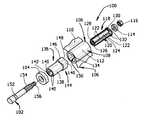
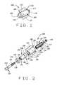
- FIG. 1is a front perspective view of a propeller assembly in accordance with one embodiment of the present invention.
- FIG. 2is an exploded view of the propeller assembly shown in FIG. 1 .
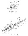
- FIG. 3is a rear perspective view of the propeller assembly shown in FIG. 1 .
- FIG. 4is an exploded view of the propeller assembly shown in FIG. 3 .
- FIG. 5is a side cross-sectional view of the propeller assembly shown in FIG. 1 .
- FIG. 6is a cross-sectional view through line 6 — 6 shown in FIG. 5 .
- FIG. 7is a side cross-sectional view of the propeller assembly shown in FIG. 1 .
- FIG. 8is a cross-sectional view through line 8 — 8 shown in FIG. 7 .
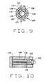
- FIG. 9is a cross-sectional view through line 9 — 9 shown in FIG. 7 .
- FIG. 10is a cross-sectional view through line 10 — 10 shown in FIG. 9 .
- the present inventionis not limited to practice in connection with a particular engine, nor is the present invention limited to practice with a particular propeller configuration.
- the present inventioncan be utilized in connection with many engines and propeller configurations. For example, a propeller having three blades is described herein.
- the present inventioncan be used in connection with propellers having any number of blades. Therefore, although the invention is described below in the context of an exemplary outboard engine and propeller configuration, the invention is not limited to practice with such engine and propeller.
- FIG. 1is a front perspective view of a propeller assembly 100 in accordance with one embodiment of the present invention.
- Propeller assembly 100is configured for being secured to a propeller shaft 102 of a marine engine.
- Propeller assembly 100includes a thrust washer 104 , a propeller 106 having an outer hub 108 and a plurality of blades 110 extending from an outer diameter hub surface 112 , a washer 114 , and a nut 116 which secures assembly 100 to propeller shaft 102 .
- propeller assembly 100rotates with propeller shaft 102 during normal operations.
- propeller 106may rotate relative to shaft 102 as described below in more detail to protect the engine drive train.
- a limp home arrangementprovides that propeller 106 may still be rotatable with propeller shaft 102 so that the operator can at least reach a dock for repairs.
- FIG. 2is an exploded view of propeller assembly 100 .
- assembly 100also includes a drive sleeve 118 having a cylindrical shaped body 120 .
- Drive sleeve 118extends from thrust washer 104 to washer 114 . Tightening of nut 116 pre-loads sleeve 118 to eliminate propeller rattle and wear, which facilitates eliminating damaging wear on load carrying thrust washer 104 .
- a plurality of splines 122extend from an outer diameter surface 124 of drive sleeve body 120 .
- a plurality of grooves 126are in an inner diameter surface 128 of drive sleeve cylindrical shaped body 120 .
- a flange 130is at one end of drive sleeve cylindrical s h aped body 120 , and a plurality of limp home projections 132 extend from drive sleeve flange 130 .
- a plurality of limp home projectionsextend from an outer hub inner diameter surface 134 to provide limp home operation, as described below in more detail.
- drive sleeve 118is cast from bronze.
- Assemblyalso includes a resilient inner hub 136 having a cylindrical shaped body 138 .
- a plurality of grooves 140are formed in an inner diameter surface 142 inner hub body 138 , and each groove 140 is located, or arranged, to receive one drive sleeve spline 122 .
- Grooves 140are tapered, as described hereinafter in more detail, to enable maximum torsional twisting and even stress distribution along hub 136 in the event of a significant impact.
- a drive flange 144is located at one end of inner hub body 138 .
- Flange 144is shaped to tightly mate with outer hub 108 .
- flange 144has four projections 146 spaced by intermediate sections 148 .
- Outer hub bore 150is shaped so that flange 144 tightly fits within bore 150 .
- Body 138has an outer diameter less than an inner diameter of bore 150 . Therefore, flange 144 tightly fits with outer hub 108 , but body 138 can rotate relative to hub 108 .
- hub 136is fabricated from resilient material.
- An exemplary resilient material suitable for fabrication of hubis a plastic. Of course, other resilient material can be used.
- Assemblyfurther includes propeller 106 having outer hub 108 with a cylindrical shape. Blades 110 extend from outer diameter surface 112 of outer hub 108 . As explained above, bore 150 extends through hub 108 and is shaped to mate with inner hub drive flange 144 to limit relative movement between inner hub drive flange 144 and outer hub 108 .
- Propeller 106can be cast from aluminum, stainless steel, or other materials.
- Propeller shaft 102has a tapered section 152 for mating with thrust washer 104 , and a splined section 154 for mating with drive sleeve grooves 126 .
- Propeller shaft 102also includes a threaded section 156 for engagement with nut 116 .
- Different enginesmay have different length splined sections, and as described below in more detail, by simply using a mating drive sleeve, one propeller (e.g., propeller 106 ) can be used on such different engines.
- FIG. 3is a rear perspective view of propeller assembly 100 .
- drive sleeve 118 and resilient inner hub 136(FIG. 3) are inserted into outer hub bore 150 .
- Drive sleeve 118can first be inserted into inner hub 136 to form a subassembly, and then the subassembly is inserted into outer hub bore 150 .
- inner hub 136can first be inserted into outer hub bore 150 , and then drive sleeve 118 is inserted into inner hub 136 .
- Thrust washer 104 and propeller 106 , inner hub 136 , and drive sleeve 118 assemblyare then pushed over propeller shaft 102 so that propeller shaft 102 extends through and engages drive sleeve 118 .
- Washer 114is then pushed over shaft 102 , and threaded nut 116 is tightened on shaft 102 to secure propeller 106 to shaft 102 .
- nut 116is tightened on propeller shaft 102 so that washer 114 is tightly secured against drive sleeve flange 130 .
- FIG. 4is an exploded view of propeller assembly 100 .
- one or more limp home projections 158extend from outer hub inner diameter surface 134 to provide limp home operation.
- drive sleeve 118rotates until further rotation is prevented by contact between drive sleeve limp home projections 132 and outer hub limp home projections 158 .
- outer hub 108begins to once again rotate with drive sleeve 118 .
- Limp home projections 132 and 158provide sufficient strength so that propeller 106 continues to rotate at low speeds without shearing of projections 132 and 158 . Projections 132 and 158 therefore facilitate continued operation of propeller 106 even after an impact which results in shearing drive sleeve splines 122 .
- FIG. 5is a side cross-sectional view of propeller assembly 100 . As shown in FIG. 5 a gap 160 between drive sleeve 118 and intermediate section 148 of resilient hub flange 144 . An inner diameter surface 162 of hub 136 tapers and extends between splines (not shown in FIG. 5) of drive sleeve 118 .
- each drive sleeve limp home projection 132extend into a space between pairs of outer hub limp home projections 158 .
- drive sleeve splines 122FIG. 4
- drive sleeve 118rotates with propeller shaft 102 and the engagement between propeller outer hub 106 and drive sleeve 118 slips until drive sleeve limp home projections 132 engage hub limp home projections 158 .
- propeller 106again rotates with propeller shaft 102 due to the engagement between propeller shaft 102 , drive sleeve 118 , and outer hub 108 .
- resilient inner hub flange projection 146tightly fits against inner diameter surface 134 of outer hub 108 .
- An outer diameter surface 164 of inner hub cylindrical shaped body 138is not in contact with outer hub 108 , and engages drive sleeve 118 via the groove and spline arrangement described above.
- FIG. 8is a cross-sectional view through line 8 — 8 shown in FIG. 7 .
- drive sleeve splines 122 at a location adjacent flange 144are not in contact with side walls of tapered grooves 140 in inner diameter surface 142 of resilient hub 136 .
- resilient hub 136twists, however, splines 122 progressively come into contact with such side walls and limit the extent of twisting by inner hub 136 .
- FIG. 9is a cross-sectional view through line 9 — 9 shown in FIG. 7 .
- splines 122are in a tight fit with tapered grooves 130 at an end of inner hub 126 opposite flange 144 .
- Such tight fitis necessary to provide that during normal operations, torque is efficiently transferred from propeller shaft 102 to propeller 106 through drive sleeve 118 and inner hub 136 .
- FIG. 10is a cross-sectional view through line 10 — 10 shown in FIG. 9 .
- Drive sleeve spline 122extends through resilient hub groove 140 , and groove 140 is tapered as described above. Again, drive sleeve spline 122 at a location adjacent flange 144 is not in contact with side walls of tapered groove 140 , and spline 122 is in a tight fit with tapered groove 140 at an end of inner hub 136 opposite flange 144 .
- the tight fit between spline 122 and groove 140provides that during normal operations, torque is efficiently transferred from propeller shaft 102 to propeller 106 through drive sleeve 118 and inner hub 136 .
- Such operational conditionis sometimes referred to herein as the normal operation mode of propeller assembly 100 .
- spline 122Upon the occurrence of an impact, and as resilient hub 136 twists, spline 122 progressively come into contact with a side wall of groove 140 . When spline 122 is in contact with one groove side wall along the entire length of wall, such contact limits further twisting by inner hub 136 .
- the operational condition in which hub 136 is twistedis sometimes referred to herein as the resilient operation mode of propeller assembly 100 .
- the torsional forcesare transmitted along a serpentine path from the end of drive sleeve 118 splined to propeller shaft 102 , to hub 136 at the location at which hub 136 is engaged to sleeve 118 , and to propeller outer hub 108 at flange 144 .
- This serpentine pathprovides the advantages of facilitating more even distribution of forces, as well as facilitating absorption of greater forces due to the length of the path as compared to a direct (e.g., radial) path from the shaft to the propeller hub.
- splines 122will shear. In the event that all splines 122 shear, then propeller shaft 102 and drive sleeve 118 rotate relative to propeller outer hub 108 until limp home projections 132 and 158 of drive sleeve 118 and outer hub 108 come into contact. If the forces are not sufficient to also shear limp home projections 132 and 158 , then propeller 106 will resume rotating with propeller shaft 102 . Such operational condition is sometimes referred to herein as the limp home operation mode of propeller assembly 100 .
- propeller assembly 100facilitates the easy replacement of resilient hub 136 .
- a usersimply removes propeller assembly 100 from propeller shaft 102 , and removes drive sleeve 118 and resilient hub 136 from within outer hub 108 .
- a replacement inner hub 136can then be utilized when reassembling propeller assembly 100 and mounting assembly 100 on propeller shaft 102 .
- propeller 106can be utilized on many different types of marine engines.
- one particular marine enginemay have splines on the propeller shaft of a first length
- another particular marine enginemay have splines on a propeller shaft of a second length, or a different number of splines or different size splines.
- Different drive sleeves having different length splines on their inner diameter surfacescan be provided.
- different drive sleevesare utilized, a same propeller can be used. That is, by providing interchangeable drive sleeves, one propeller can be used in conjunction with many different type engines.
- drive sleeve or resilient hubcould be sold in kit form.
- kit formdifferent kits containing different drive sleeves specified for particular engine types could be provided.
- a kitincludes both a drive sleeve and a resilient replaceable inner hub.
Landscapes
- Chemical & Material Sciences (AREA)
- Engineering & Computer Science (AREA)
- Combustion & Propulsion (AREA)
- Mechanical Engineering (AREA)
- Ocean & Marine Engineering (AREA)
- Shafts, Cranks, Connecting Bars, And Related Bearings (AREA)
Abstract
Description
Claims (31)
Priority Applications (2)
| Application Number | Priority Date | Filing Date | Title |
|---|---|---|---|
| US09/547,009US6383042B1 (en) | 2000-04-11 | 2000-04-11 | Axial twist propeller hub |
| JP2001112455AJP2001354194A (en) | 2000-04-11 | 2001-04-11 | Axially twisting propeller hub |
Applications Claiming Priority (1)
| Application Number | Priority Date | Filing Date | Title |
|---|---|---|---|
| US09/547,009US6383042B1 (en) | 2000-04-11 | 2000-04-11 | Axial twist propeller hub |
Publications (1)
| Publication Number | Publication Date |
|---|---|
| US6383042B1true US6383042B1 (en) | 2002-05-07 |
Family
ID=24182974
Family Applications (1)
| Application Number | Title | Priority Date | Filing Date |
|---|---|---|---|
| US09/547,009Expired - LifetimeUS6383042B1 (en) | 2000-04-11 | 2000-04-11 | Axial twist propeller hub |
Country Status (2)
| Country | Link |
|---|---|
| US (1) | US6383042B1 (en) |
| JP (1) | JP2001354194A (en) |
Cited By (19)
| Publication number | Priority date | Publication date | Assignee | Title |
|---|---|---|---|---|
| US6478543B1 (en)* | 2001-02-12 | 2002-11-12 | Brunswick Corporation | Torque transmitting device for mounting a propeller to a propeller shaft of a marine propulsion system |
| US6609892B1 (en)* | 2000-11-21 | 2003-08-26 | Bombardier Motor Corporation Of America | Propeller hub |
| US6672834B2 (en)* | 2001-12-21 | 2004-01-06 | Turning Point Propellers, Inc. | Removable propeller assembly incorporating breakaway elements |
| US20040063290A1 (en)* | 2002-09-30 | 2004-04-01 | Applied Materials, Inc. | Thermal flux annealing influence of buried species |
| US20050186861A1 (en)* | 2004-02-20 | 2005-08-25 | Powers Charles S. | Exterior shear shoulder assembly for outboard motors and outdrives |
| US20060010847A1 (en)* | 2004-07-01 | 2006-01-19 | George Vandyke | Blade slippage apparatus |
| US7086836B1 (en) | 2004-09-02 | 2006-08-08 | Brunswick Corporation | Dual rate torque transmitting device for a marine propeller |
| US20060263219A1 (en)* | 2005-05-19 | 2006-11-23 | Peter Dean | Boat propeller |
| US20080139061A1 (en)* | 2006-11-14 | 2008-06-12 | Liheng Chen | Spindle with overmolded bushing |
| US20090163089A1 (en)* | 2007-12-20 | 2009-06-25 | Liheng Chen | Propeller Assembly Incorporating Spindle With Fins And Overmolded Bushing |
| US20110212657A1 (en)* | 2010-02-26 | 2011-09-01 | Yamaha Hatsudoki Kabushiki Kaisha | Propeller unit for marine vessel propulsion device and marine vessel propulsion device including the same |
| US8262358B1 (en) | 2009-05-26 | 2012-09-11 | The Boeing Company | Ultra-light weight self-lubricating propeller hub |
| US8277269B1 (en) | 2010-07-09 | 2012-10-02 | Brunswick Corporation | Torque transmitting device and system for marine propulsion |
| US9017118B1 (en) | 2012-01-31 | 2015-04-28 | Brp Us Inc. | Gear case assembly for a marine outboard engine and method of assembly thereof |
| US20170210456A1 (en)* | 2016-01-27 | 2017-07-27 | Solas Science & Engineering Co., Ltd. | Two-piece axle bushing and marine propeller using same |
| CN107042882A (en)* | 2016-02-05 | 2017-08-15 | 般若科技股份有限公司 | The double-joint type axle sleeve and marine propeller of marine propeller |
| WO2018029480A1 (en)* | 2016-08-10 | 2018-02-15 | Superprop Limited | Improvements to a drive system for a propeller |
| USD894055S1 (en)* | 2018-09-11 | 2020-08-25 | Brunswick Corporation | Shock absorbing hub assembly for supporting a propeller on a marine propulsion apparatus |
| CN111677773A (en)* | 2020-06-19 | 2020-09-18 | 得利升(青岛)智能制造有限公司 | Internal transmission structure of propeller |
Families Citing this family (3)
| Publication number | Priority date | Publication date | Assignee | Title |
|---|---|---|---|---|
| JP5004157B2 (en)* | 2006-05-09 | 2012-08-22 | 日本発條株式会社 | Connection member for operation shaft, and remote operation device provided with this connection member |
| JP5015751B2 (en)* | 2007-12-14 | 2012-08-29 | トヨタ自動車株式会社 | Shaft coupling structure |
| KR20210130339A (en) | 2020-04-22 | 2021-11-01 | 현대자동차주식회사 | Propelller shaft for vehicle |
Citations (5)
| Publication number | Priority date | Publication date | Assignee | Title |
|---|---|---|---|---|
| US4566855A (en)* | 1981-08-28 | 1986-01-28 | Costabile John J | Shock absorbing clutch assembly for marine propeller |
| US5201679A (en)* | 1991-12-13 | 1993-04-13 | Attwood Corporation | Marine propeller with breakaway hub |
| US5252028A (en)* | 1992-09-14 | 1993-10-12 | Lobosco Sam | Marine propeller assembly with shock absorbing hub and easily replaceable propeller housing |
| US5630704A (en)* | 1996-03-19 | 1997-05-20 | Brunswick Corporation | Propeller drive sleeve with asymmetric shock absorption |
| US5967751A (en)* | 1997-09-16 | 1999-10-19 | Chen; Fu Daul | Propeller assembly for marine engine |
- 2000
- 2000-04-11USUS09/547,009patent/US6383042B1/ennot_activeExpired - Lifetime
- 2001
- 2001-04-11JPJP2001112455Apatent/JP2001354194A/enactivePending
Patent Citations (5)
| Publication number | Priority date | Publication date | Assignee | Title |
|---|---|---|---|---|
| US4566855A (en)* | 1981-08-28 | 1986-01-28 | Costabile John J | Shock absorbing clutch assembly for marine propeller |
| US5201679A (en)* | 1991-12-13 | 1993-04-13 | Attwood Corporation | Marine propeller with breakaway hub |
| US5252028A (en)* | 1992-09-14 | 1993-10-12 | Lobosco Sam | Marine propeller assembly with shock absorbing hub and easily replaceable propeller housing |
| US5630704A (en)* | 1996-03-19 | 1997-05-20 | Brunswick Corporation | Propeller drive sleeve with asymmetric shock absorption |
| US5967751A (en)* | 1997-09-16 | 1999-10-19 | Chen; Fu Daul | Propeller assembly for marine engine |
Cited By (31)
| Publication number | Priority date | Publication date | Assignee | Title |
|---|---|---|---|---|
| US6609892B1 (en)* | 2000-11-21 | 2003-08-26 | Bombardier Motor Corporation Of America | Propeller hub |
| US6478543B1 (en)* | 2001-02-12 | 2002-11-12 | Brunswick Corporation | Torque transmitting device for mounting a propeller to a propeller shaft of a marine propulsion system |
| US6672834B2 (en)* | 2001-12-21 | 2004-01-06 | Turning Point Propellers, Inc. | Removable propeller assembly incorporating breakaway elements |
| US20040063290A1 (en)* | 2002-09-30 | 2004-04-01 | Applied Materials, Inc. | Thermal flux annealing influence of buried species |
| US20050186861A1 (en)* | 2004-02-20 | 2005-08-25 | Powers Charles S. | Exterior shear shoulder assembly for outboard motors and outdrives |
| US7200982B2 (en) | 2004-07-01 | 2007-04-10 | Briggs & Stratton Corporation | Blade slippage apparatus |
| US20060010847A1 (en)* | 2004-07-01 | 2006-01-19 | George Vandyke | Blade slippage apparatus |
| US7086836B1 (en) | 2004-09-02 | 2006-08-08 | Brunswick Corporation | Dual rate torque transmitting device for a marine propeller |
| US20060263219A1 (en)* | 2005-05-19 | 2006-11-23 | Peter Dean | Boat propeller |
| US7223073B2 (en) | 2005-05-19 | 2007-05-29 | Peter Dean | Boat propeller |
| US20080139061A1 (en)* | 2006-11-14 | 2008-06-12 | Liheng Chen | Spindle with overmolded bushing |
| US7717678B2 (en) | 2006-11-14 | 2010-05-18 | Turning Point Propellers, Inc. | Spindle with overmolded bushing |
| EP2242681A4 (en)* | 2007-12-20 | 2013-03-06 | Turning Point Propellers Inc | Propeller assembly incorporating spindle with fins and overmolded bushing |
| US20090163089A1 (en)* | 2007-12-20 | 2009-06-25 | Liheng Chen | Propeller Assembly Incorporating Spindle With Fins And Overmolded Bushing |
| US7708526B2 (en) | 2007-12-20 | 2010-05-04 | Turning Point Propellers, Inc. | Propeller assembly incorporating spindle with fins and overmolded bushing |
| US8262358B1 (en) | 2009-05-26 | 2012-09-11 | The Boeing Company | Ultra-light weight self-lubricating propeller hub |
| US8632307B1 (en) | 2009-05-26 | 2014-01-21 | The Boeing Company | Ultra-light weight self-lubricating propeller hub |
| US20110212657A1 (en)* | 2010-02-26 | 2011-09-01 | Yamaha Hatsudoki Kabushiki Kaisha | Propeller unit for marine vessel propulsion device and marine vessel propulsion device including the same |
| US8419489B2 (en)* | 2010-02-26 | 2013-04-16 | Yamaha Hatsudoki Kabushiki Kaisha | Propeller unit for marine vessel propulsion device and marine vessel propulsion device including the same |
| US8277269B1 (en) | 2010-07-09 | 2012-10-02 | Brunswick Corporation | Torque transmitting device and system for marine propulsion |
| US9017118B1 (en) | 2012-01-31 | 2015-04-28 | Brp Us Inc. | Gear case assembly for a marine outboard engine and method of assembly thereof |
| US20170210456A1 (en)* | 2016-01-27 | 2017-07-27 | Solas Science & Engineering Co., Ltd. | Two-piece axle bushing and marine propeller using same |
| EP3199447A1 (en)* | 2016-01-27 | 2017-08-02 | Solas Science & Engineering Co., Ltd. | Two-piece axle bushing and marine propeller using same |
| CN107042882A (en)* | 2016-02-05 | 2017-08-15 | 般若科技股份有限公司 | The double-joint type axle sleeve and marine propeller of marine propeller |
| WO2018029480A1 (en)* | 2016-08-10 | 2018-02-15 | Superprop Limited | Improvements to a drive system for a propeller |
| GB2567607A (en)* | 2016-08-10 | 2019-04-17 | Superprop Ltd | Improvements to a drive system for a propeller |
| US10933960B2 (en) | 2016-08-10 | 2021-03-02 | Superprop Limited | Drive system for a propeller |
| GB2567607B (en)* | 2016-08-10 | 2021-08-18 | Superprop Ltd | Improvements to a drive system for a propeller |
| USD894055S1 (en)* | 2018-09-11 | 2020-08-25 | Brunswick Corporation | Shock absorbing hub assembly for supporting a propeller on a marine propulsion apparatus |
| CN111677773A (en)* | 2020-06-19 | 2020-09-18 | 得利升(青岛)智能制造有限公司 | Internal transmission structure of propeller |
| CN111677773B (en)* | 2020-06-19 | 2024-04-19 | 得利升(青岛)智能制造有限公司 | Inside transmission structure of screw |
Also Published As
| Publication number | Publication date |
|---|---|
| JP2001354194A (en) | 2001-12-25 |
Similar Documents
| Publication | Publication Date | Title |
|---|---|---|
| US6383042B1 (en) | Axial twist propeller hub | |
| US4566855A (en) | Shock absorbing clutch assembly for marine propeller | |
| US5201679A (en) | Marine propeller with breakaway hub | |
| DE69205262T2 (en) | Drive bush for propeller. | |
| US6685432B2 (en) | Hub assembly for marine propeller | |
| EP1961655B1 (en) | Propeller for boat | |
| US6478543B1 (en) | Torque transmitting device for mounting a propeller to a propeller shaft of a marine propulsion system | |
| US7717678B2 (en) | Spindle with overmolded bushing | |
| US7086836B1 (en) | Dual rate torque transmitting device for a marine propeller | |
| US6609892B1 (en) | Propeller hub | |
| US4204806A (en) | Folding propeller | |
| US9400029B2 (en) | Damper unit for vessel propulsion apparatus, propeller for vessel propulsion apparatus, and vessel propulsion apparatus | |
| US6659818B2 (en) | Shock-absorbing propeller assembly | |
| US7708526B2 (en) | Propeller assembly incorporating spindle with fins and overmolded bushing | |
| US4826458A (en) | Gear box with retained drive mechanism | |
| WO2006002463A1 (en) | Interchangeable propeller hub system | |
| US7223074B2 (en) | Propeller shaft arrangement, propeller arrangement, adaptive arrangement and propulsion arrangement | |
| US6354802B1 (en) | Propeller assembly including a spiral wound spring | |
| US6193572B1 (en) | Propeller assembly including a cantilever spring | |
| US4310285A (en) | Folding propeller with rubber hub | |
| US6799946B1 (en) | Propeller assembly | |
| US5522743A (en) | Marine propeller with rubber bushing having lobular configuration | |
| WO2003074355A1 (en) | Propeller arrangement for marine drive units | |
| US11299246B1 (en) | Propeller assembly with noise reducing hub arrangement | |
| JP3037057U (en) | Ship screw |
Legal Events
| Date | Code | Title | Description |
|---|---|---|---|
| AS | Assignment | Owner name:OUTBOARD MARINE CORPORATION, ILLINOIS Free format text:ASSIGNMENT OF ASSIGNORS INTEREST;ASSIGNOR:NEISEN, GERALD F.;REEL/FRAME:010757/0019 Effective date:20000404 | |
| STCF | Information on status: patent grant | Free format text:PATENTED CASE | |
| RR | Request for reexamination filed | Effective date:20031020 | |
| AS | Assignment | Owner name:BOMBARDIER MOTOR CORPORATION, FLORIDA Free format text:NUNC PRO TUNC ASSIGNMENT;ASSIGNOR:OUTBOARD MARINE CORPORATION;REEL/FRAME:014196/0565 Effective date:20031211 | |
| AS | Assignment | Owner name:BOMBARDIER RECRREATIONAL PRODUCTS INC., CANADA Free format text:ASSIGNMENT OF ASSIGNORS INTEREST;ASSIGNOR:BOMBARDIER MOTOR CORPORATION OF AMERICA;REEL/FRAME:014532/0204 Effective date:20031218 | |
| AS | Assignment | Owner name:BANK OF MONTREAL, CANADA Free format text:SECURITY INTEREST;ASSIGNOR:BOMBARDIER RECREATIONAL PRODUCTS INC.;REEL/FRAME:014556/0334 Effective date:20040130 | |
| AS | Assignment | Owner name:BRP US INC., WISCONSIN Free format text:ASSIGNMENT OF ASSIGNORS INTEREST;ASSIGNOR:BOMBARDIER RECREATIONAL PRODUCTS INC.;REEL/FRAME:016087/0282 Effective date:20050131 | |
| FPAY | Fee payment | Year of fee payment:4 | |
| B1 | Reexamination certificate first reexamination | Free format text:THE PATENTABILITY OF CLAIMS 1-31 IS CONFIRMED. | |
| AS | Assignment | Owner name:BANK OF MONTREAL, AS ADMINISTRATIVE AGENT, CANADA Free format text:SECURITY AGREEMENT;ASSIGNOR:BRP US INC.;REEL/FRAME:018350/0269 Effective date:20060628 | |
| FEPP | Fee payment procedure | Free format text:PAYOR NUMBER ASSIGNED (ORIGINAL EVENT CODE: ASPN); ENTITY STATUS OF PATENT OWNER: LARGE ENTITY | |
| FPAY | Fee payment | Year of fee payment:8 | |
| FPAY | Fee payment | Year of fee payment:12 |