US6381878B1 - Composite cleat for athletic shoe - Google Patents
Composite cleat for athletic shoeDownload PDFInfo
- Publication number
- US6381878B1 US6381878B1US09/703,238US70323800AUS6381878B1US 6381878 B1US6381878 B1US 6381878B1US 70323800 AUS70323800 AUS 70323800AUS 6381878 B1US6381878 B1US 6381878B1
- Authority
- US
- United States
- Prior art keywords
- cleat
- disk
- composite
- center component
- component
- Prior art date
- Legal status (The legal status is an assumption and is not a legal conclusion. Google has not performed a legal analysis and makes no representation as to the accuracy of the status listed.)
- Expired - Fee Related
Links
- 239000002131composite materialSubstances0.000titleclaimsabstractdescription25
- 230000000386athletic effectEffects0.000titleclaimsdescription22
- 229910052755nonmetalInorganic materials0.000claimsabstractdescription23
- 239000000463materialSubstances0.000claimsdescription55
- 239000002245particleSubstances0.000claimsdescription12
- HBMJWWWQQXIZIP-UHFFFAOYSA-Nsilicon carbideChemical compound[Si+]#[C-]HBMJWWWQQXIZIP-UHFFFAOYSA-N0.000claimsdescription7
- 229910010271silicon carbideInorganic materials0.000claimsdescription7
- 150000002825nitrilesChemical class0.000claimsdescription6
- 229920003048styrene butadiene rubberPolymers0.000claimsdescription6
- 229910052751metalInorganic materials0.000abstractdescription13
- 239000002184metalSubstances0.000abstractdescription13
- 244000025254Cannabis sativaSpecies0.000abstractdescription3
- 235000019589hardnessNutrition0.000description8
- 230000000149penetrating effectEffects0.000description5
- 239000003082abrasive agentSubstances0.000description4
- 229920003023plasticPolymers0.000description4
- 239000004033plasticSubstances0.000description4
- 239000000919ceramicSubstances0.000description3
- 150000001875compoundsChemical class0.000description3
- 235000021384green leafy vegetablesNutrition0.000description3
- 239000000203mixtureSubstances0.000description3
- 229920000642polymerPolymers0.000description3
- 230000000153supplemental effectEffects0.000description3
- 241000219793TrifoliumSpecies0.000description2
- 238000005299abrasionMethods0.000description2
- 238000010276constructionMethods0.000description2
- 229910003460diamondInorganic materials0.000description2
- 239000010432diamondSubstances0.000description2
- 229920001971elastomerPolymers0.000description2
- 239000000806elastomerSubstances0.000description2
- 230000005484gravityEffects0.000description2
- 238000009434installationMethods0.000description2
- 238000000034methodMethods0.000description2
- 238000000465mouldingMethods0.000description2
- 230000002093peripheral effectEffects0.000description2
- 230000001012protectorEffects0.000description2
- 229920001875EbonitePolymers0.000description1
- 238000007792additionMethods0.000description1
- 239000003086colorantSubstances0.000description1
- 238000007796conventional methodMethods0.000description1
- 230000009977dual effectEffects0.000description1
- 239000013536elastomeric materialSubstances0.000description1
- 238000003780insertionMethods0.000description1
- 230000037431insertionEffects0.000description1
- 230000014759maintenance of locationEffects0.000description1
- 238000004519manufacturing processMethods0.000description1
- 230000013011matingEffects0.000description1
- 239000002905metal composite materialSubstances0.000description1
- 150000002843nonmetalsChemical class0.000description1
- TWNQGVIAIRXVLR-UHFFFAOYSA-Noxo(oxoalumanyloxy)alumaneChemical compoundO=[Al]O[Al]=OTWNQGVIAIRXVLR-UHFFFAOYSA-N0.000description1
- 238000009877renderingMethods0.000description1
- 238000005070samplingMethods0.000description1
- 238000006748scratchingMethods0.000description1
- 230000002393scratching effectEffects0.000description1
- BWMISRWJRUSYEX-SZKNIZGXSA-Nterbinafine hydrochlorideChemical compoundCl.C1=CC=C2C(CN(C\C=C\C#CC(C)(C)C)C)=CC=CC2=C1BWMISRWJRUSYEX-SZKNIZGXSA-N0.000description1
- 201000004647tinea pedisDiseases0.000description1
- UONOETXJSWQNOL-UHFFFAOYSA-Ntungsten carbideChemical compound[W+]#[C-]UONOETXJSWQNOL-UHFFFAOYSA-N0.000description1
- 125000000391vinyl groupChemical group[H]C([*])=C([H])[H]0.000description1
- 229920002554vinyl polymerPolymers0.000description1
Images


Classifications
- A—HUMAN NECESSITIES
- A43—FOOTWEAR
- A43C—FASTENINGS OR ATTACHMENTS OF FOOTWEAR; LACES IN GENERAL
- A43C15/00—Non-skid devices or attachments
- A43C15/16—Studs or cleats for football or like boots
- A—HUMAN NECESSITIES
- A43—FOOTWEAR
- A43C—FASTENINGS OR ATTACHMENTS OF FOOTWEAR; LACES IN GENERAL
- A43C15/00—Non-skid devices or attachments
- A43C15/16—Studs or cleats for football or like boots
- A43C15/162—Studs or cleats for football or like boots characterised by the shape
- A43C15/164—Studs or cleats for football or like boots characterised by the shape having a circular cross section
- A—HUMAN NECESSITIES
- A43—FOOTWEAR
- A43C—FASTENINGS OR ATTACHMENTS OF FOOTWEAR; LACES IN GENERAL
- A43C15/00—Non-skid devices or attachments
- A43C15/16—Studs or cleats for football or like boots
- A43C15/168—Studs or cleats for football or like boots with resilient means, e.g. shock absorbing means
Definitions
- the present inventionrelates to a cleat or spike for an athletic shoe and particularly to a non-metal, composite cleat for a golf shoe constructed from two or more polymeric materials having different densities and/or hardnesses.
- Spikes or cleats for athletic shoeshave long been used to provide traction in dirt and grass.
- Such spikes or cleatstypically have been made of metal or other relatively hard materials.
- Shoe cleats or spikesparticularly those that are removable or replaceable, have been known in the art for at least the last 80 years.
- Supplemental sole protectors that attach to a shoehave also been known for over 100 years.
- U.S. Pat. No. 2,509,980 to McCallumwhich issued in 1950, discloses a removable shoe cleat for use with golf shoes.
- the cleathas a circular or disk-like base.
- the cleathas a conical stud portion with a plurality of channels having rounded interiors.
- the cleathas three curved wings that radiate out from the center and which provide for the optimal gripping of surfaces.
- the cleatcomprises a threaded member that screws into an aperture along the underside of a shoe.
- U.S. Pat. No. 2,895,235 to Melchionadescribes a removable spike for use on sport shoes, such as golf shoes.
- the spikehas a circular base and externally projecting ribs radially extending from the boss or slightly raised center portion of the spike.
- the ribshave curved sides or edges.
- the spikewhich is stamped from metal, has a threaded member that screws into an aperture on the bottom of a shoe.
- Flemming's cleatdoes not solve a problem often encountered by golfers. That is the need to walk not just over greens, but also over smooth hard surfaces peripheral to the playing area. Like traditional metal cleats, on a hard surface, the Flemming cleat provides little traction and also does not address the additional problems of scratching the surfaces that are walked on, which in some areas peripheral to a golf course is of some concern.
- the golf cleat industryhas focused on an alternative to the more commonly used metal golf spikes.
- the newer alternative spikes or cleatsare typically formed from a non-turf penetrating, resilient polymeric material. These alternative cleats are often described as being “green-friendly” because of their non-turf penetrating nature. In addition to being “green-friendly”, the alternative. cleats have been found to be easier on the human body compared to previously used metal cleats.
- the present inventionprovides a cleat comprising a stud with a composite body for an athletic shoe that provides traction both on hard and smooth surfaces and on greens in a relatively non-penetrating manner.
- an exchangeable cleat having a non-metal bodyis provided.
- the non-metal bodyis formed of a material having first durometer (or hardness) and has a central portion formed of a material having a second durometer (or hardness).
- the central portionpreferably extends a short distance away from a disk of surrounding material having a different durometer than the central portion, allowing (in one embodiment) a gripping central area for walking on harder surfaces.
- the wider, surrounding cleatprovides traction on the turf, for example, during a golf swing.
- the removable cleatcan be used year-round in golf without sacrificing performance and while providing damage avoidance to greens.
- the inventionalso includes athletic shoes provided with a plurality of dual-density cleats.
- the cleatshave a body that is long wearing and slip resistant by utilizing polymers and/or plastics.
- the non-metal, central portionpreferably extends only a short distance beyond a surrounding turf-gripping portion, and provides non-penetrating but effective traction, e.g., during a golf swing.
- An additional embodimentincludes a non-metal cleat having enhanced turf gripping properties which are imparted by a plurality of traction elements having arcuate ridges which grip or “bite” the turf during a golf swing.
- a further embodiment of the inventionprovides for an abrasive material to be incorporated into or onto either or both of the material of a first durometer and material of a second durometer utilized in the non-metal body of the cleat.
- the materialsare selected to provide a long wearing, slip-resistant, non-metal golf cleat that alleviates damage to the surface of a golf green, yet provides traction on grass and wears similar to conventional metal spikes.
- FIG. 1is a perspective view of a cleat for athletic shoes in accordance with one embodiment of the present invention.
- FIG. 2top view of the cleat of FIG. 1 .
- FIG. 3is section view of a composite cleat taken along line 3 — 3 of FIG. 2 .
- FIG. 4is isomeric view of a cloverleaf stud base according to one illustrative embodiment of the invention.
- FIG. 5is a cutaway view of a cloverleaf stud base and molded disk portion according to one illustrative embodiment of the invention.
- FIG. 6is a cutaway view of a cleat for an athletic shoes according to one illustrative embodiment of the invention.
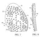
- FIG. 7if plan view of a sole of a shoe having mounting areas for receiving a plurality of cleats in accord with the present invention.
- FIG. 8is a side view illustrating one side of the sole of FIG. 7 .
- FIG. 9is a perspective view of a cleat for athletic shoes in accordance with a further embodiment of the present invention.
- FIG. 10is a top view of the cleat of FIG. 9 .
- FIG. 11 and FIG. 11Aare bottom views of the cleat of FIG. 9 wherein FIG. 11A has raised portions in an alternative embodiment for gripping the sole of a shoe.
- FIG. 12 and FIG. 12Aare side views of the cleats of FIG. 11 and FIG. 11 A.
- FIG. 13 and FIG. 13Aare rotated views of the cleats of FIG. 12 and FIG. 12 A.
- FIG. 14is an exploded view of a three part alternative construction of a cleat of the present invention.
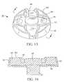
- FIG. 15is perspective view of a cleat of FIG. 9 having a portion of the cleat worn away.
- FIG. 16is a cross-sectional view of the cleat of FIG. 15 along line C—C.
- FIG. 17is a cross-sectional view of the cleat of FIG. 15 along line C—C showing an alternative four part construction of the present invention.
- FIGS. 1-3a non-metal composite cleat 2 is illustrated in FIGS. 1-3.
- the cleatis held to the sole of an athletic shoe by an integral stud 4 .
- stud 4preferably comprises external mounting thread 6 , allowing the stud 4 to be turned into one of several matingly threaded mounts in the sole of a shoe.
- a mounting toolengages the cleat body 2 at tool fittings 20 to allow the cleat to be firmly rotated into tight engagement within the internally threaded mount of the shoe.
- the cleatis molded in two steps about a metal clover-shaped or “cloverleaf” base 8 as depicted in FIG. 3 .
- a disk portion 10is molded about the base 8 to provide an intermediate component as depicted in FIG. 5 .
- Disk 10is shaped with a plurality of gripping sections 12 , which are constructed and arranged to grip the turf, e.g., of a golf course during the player's swing, and prohibit slipping of the sole of the golf shoe.
- the disk portionpreferably is also molded to form tool fittings so as to correspond to two of the holes 20 in the cloverleaves of base 8 surrounded by the wings 12 .
- a center portion 18is formed preferably protruding from the upper major surface of the disk as depicted in FIG. 6 .
- the upper, or second, major surfaceis the ground-contacting surface.
- the frustoconical cavity 22may further have ribs or threads 24 on the surface in order to aid in the retention of the center portion 18 .
- the frustoconical cavity 22is convex to aid in the molding process, but can be concave or cylindrical.
- the relative geometric shapes of the disk portion 10 and the center portion 18can have any mating shape, subject only to the desire of the designer and the ability to manufacture the part.
- the body of the cleatcomprises a base which is attached to stud 4 and supports disk 10 at a major surface thereof.
- the stud, base, and disk portionsare formed integrally.
- a center portion 18preferably protruding from the upper major surface of the disk, is located within the disk.
- the gripping sections 12are raised from the base 8 , and extend from the center portion 18 to the outer edge of the disk 10 .
- the circumference of the disk 10is shown to comprise a shoulder area, rendering the disk a horizontal frustoconical section.
- a typical gripping section 12and curves down toward the base 8 joining the straight side wall of an adjacent gripping section 12 .
- Each gripping sectionextends outward from the center section 18 to the circumference of the disk.
- the gripping sectionhas an edge formed by the top horizontal surface of the disk and the straight wall.
- the edgepreferably extends from the center portion 18 , along a tangent to the rounded center portion, to the outer diameter of the disk.
- segments having two substantially straight wallscan be located to facilitate access to and use of the tool fittings.
- the slightly higher, preferably rounded, center portion 18is made of a material having a durometer (or hardness) which is different than the material used to make the disk.
- the different durometer of the center portioncan provide slip resistance when walking on most hard, smooth, and/or dry surfaces.
- the gripping sections 12may be less than, greater than, or equivalent to the height of the center 18 .
- the vertical protrusionsmay be a combination of varying heights.
- the durometer (or hardness) of the disk portion of the bodyis between about 60-67 on the Shore A scale (10 sec delay). More preferably the durometer is in the range of 55 to 75 on the Shore A scale (10 sec delay).
- the center portionpreferably has a durometer of about 55-62 on the Shore A scale (10 sec delay). More preferably, the durometer is in the range of 49-65 on the Shore A scale (10 sec delay).
- the disk portionmay be comprised of elastomers, plastics or other polymers and typically has a specific gravity of about 0.99 g/cc, more preferably in the range of 0.85-1.05 g/cc.
- the center portionmay be comprised of elastomers, plastics or other polymers and typically has a specific gravity of about 0.95 g/cc, more preferably has a slip resistance equivalent to a better than 1.11/1.11 (dry/wet) on vinyl tile in accord with ASTM F-489, and an NBS abrasion index of about 175 or better.
- the disk portionis typically of a material having an NBS abrasion index of about 225 or better.
- the material for the center portionis HP136X-60A footwear compound and the disk portion is HP100X-65A footwear compound, both purchased from UNIComp, Hampton, N.H.
- cleatconsists of either of the center portion or disk portion of the cleat being formed from nitrile styrene butadiene rubber (NSBR).
- NBRnitrile styrene butadiene rubber
- the above referenced materialsmay be reversed with respect to the disc and center portions.
- a further embodiment of the inventionprovides for an abrasive material to be incorporated into or onto either or both of the material of a first durometer and material of a second durometer utilized in the non-metal body of the cleat.
- the materials which can be utilized as abrasive materialsinclude, but are not limited to, silicon carbide, tungsten carbide, natural diamond, artificial diamond, aluminum oxide, or other substantially wear resistant compounds. Particles are sized and distributed either intimately within either or both of the materials utilized in forming the non-metal portions of the cleat or can be distributed along the ground engaging surface of the cleat.
- a plurality of cleats having different degrees of abrasivenessare provided.
- cleats with a higher degree of abrasivenesscan be attached at portions of the sole of the shoe where increased anti-slip and increased ground gripping is desired.
- different degrees of abrasivenessmay be achieved by varying the size of the particles between different cleats, by varying the density of the particles used in the different cleats, by varying the types of materials used as abrasives in the cleats, or by varying the depth into which the particles are imbeded into the cleats.
- a cleat 40which has a clover leaf base 96 and a non-metal body 100 .
- the clover leaf base 96is joined to an integral stud 62 which may be matingly mounted to mounts or receptacles in the sole of a golf shoe.
- Non-metal body 100is comprised of a first component 41 which surrounds a second protruding center 48 and underlying component 54 .
- the first component 41is formed of a first material having a first durometer (or hardness) and the second center component 48 (which protrudes from the upper surface of the underlying component 54 ) and underlying component 54 are formed from a second material having a second durometer (or hardness).
- center component 48 and the underlying component 54may be formed of different materials having different durometers or hardnesses.
- FIG. 17a cleat cross-sectional view along line C—C of FIG. 15 depicts an embodiment where center component 48 is separate from underlying component 54 .
- the first materialmay have a first durometer which is greater than the durometer of the second material. In an alternative embodiment, the first material may have a durometer which is less than the durometer of the second material.
- the first and second materialsmay be of different colors and/or compositions so that when the first material wears away the second material will noticeably show through (FIG. 15 ).
- FIGS. 9, 10 and 14show an alternative cleat embodiment 40 according to the invention comprising a non-metal body 100 comprised of a first, outer component 41 , 70 which surrounds a second central 48 and underlying component 54 .
- the first and outer component 41has traction gripping elements 42 which extend away from a shoe sole to form an outermost ground contacting surface 44 .
- the outermost ground contacting surface 44consists of an arcuate rib which has a rounded end 68 , a central portion 66 which is a greater distance from base 102 than as rounded end 68 , and an angular end 67 at the opposing end of the arcuate rib which is equidistant from base 102 as rounded end 68 thereby imparting a slightly curved surface to the arcuate rib of traction element 42 , the curved surface being curved away from the generally flat surface of the base 102 of the cleat.
- Each traction gripping element 42has two gradual curved slopes 45 which curve inwardly and downwardly to a downwardly sloping rib 46 .
- the downwardly sloping rib 46extends toward the center portion of the cleat 48 from the center or middle of the ground contacting surface 44 of traction gripping element 42 .
- the downwardly sloping rib element 46has a generally flat surface, functioning as a turf grabbing element for the cleat.
- Apertures or tool fittings 52are provided for insertion of a cleat installation/removal tool (not shown).
- FIG. 11A bottom view of the cleat 40 is shown in FIG. 11 and an alternative bottom is shown in FIG. 11 A.
- a centrally located stud 62is provided which may be a threaded stud as depicted in FIG. 11 and FIG. 11 A.
- Raised portions 64are present on the underside surface of base 102 to provide for frictional contact with the bottom of an athletic shoe into which the cleats are reversibly mounted or attached.
- FIGS. 12 and 12Arepresent a side view of the cleat of FIG. 11 and FIG. 11A along view lines A—A and A 1 —A 1 .
- FIGS. 13 and 13Arepresent a side view of the cleat of FIG. 11 and FIG. 11A along view lines B—B and B 1 —B 1 .
- traction gripping elements 42have an arcuate shape with central portion 66 being a greater distance from base 102 than either rounded end portion 68 or angular end portion 67 imparting a curved surface thereto.
- FIG. 14An exploded view of a cleat according to the invention is presented in FIG. 14 showing an upper or top, outer or ground contact surface portion 70 , a central underlying portion 80 and a base or sole contact portion 90 .
- the upper or top, outer portion 70consists of the first component 41 and has an aperture 72 for receiving the protrusion 48 from the central, underlying portion 80 , which may extend beyond the surface 50 of outer portion 70 .
- Recessed areas 74 between traction elements 42receive protrusions 54 from the central underlying portion 80 .
- the top, outer or ground contact surface portion 70has apertures 73 (shown in dotted lines) within each of traction elements 42 for receiving similarly shaped elements 83 extending away from the upper surface 86 of the central underlying portion 80 .
- the upper surface 84 of element 83is slightly above the outer surface 50 of the top, outer portion of the cleat when placed within aperture 73 .
- Base element 90is placed underneath central underlying portion 80 wherein two opposing apertures 94 align with apertures 82 and corresponding apertures 22 to form continuous holes in which a cleat installation/replacement tool can be used.
- Base portion 96is then integrally molded within central, underlying portion 80 .
- FIG. 15represents a worn version of the cleat 40 with central, underlying portion elements 83 , 84 showing when the top portion of traction elements 42 are worn away.
- FIG. 15represents a worn version of the cleat 40 with central, underlying portion elements 83 , 84 showing when the top portion of traction elements 42 are worn away.
- an indication of cleat wearis visible when the color or composition of element 83 begins to show through.
- FIG. 16represents a cross sectional view of the worn cleat of FIG. 15 along view line C—C.
- the stud 62can be metal and joined to the non-metal body by conventional means.
- the base 96 and the stud 62can also be integral and formed of metal with the central underlying portion attached thereto by known joining methods, including mechanical fastening.
- the stud 62 and/or base 96can be made of the same material as the central underlying portion. Additional conventional fastening systems such as those described in U.S. Pat. Nos. 5,768,809, Des. 391,048 and Des. 388,949 can also be utilized in the present invention.
- the inventionalso provides athletic shoes, such as golf shoes, having a plurality of cleats of the present invention mounted in the soles.
- the sole of an athletic shoeis provided with a plurality mounting areas for the cleats.
- the sole 30is a molded sole having seven mounting areas 31 for cleats. More or less cleats can be used according to the specific application.
- the solealso has a plurality of integrally molded nubs 35 , which can have a variety of shapes. The nubs 35 provide additional stability.
- the mounting areasinclude an internally threaded socket or other appropriate receptacle for receiving the stud of the cleat.
- the socketscan be molded of the same material as the sole or can be parts of metal inserts molded into the sole by conventional techniques. Cleats as described hereinbefore and according to any one of FIGS. 1-6 and 9 - 17 may be releasably mounted in mounting area 31 of sole 30 .
Landscapes
- Footwear And Its Accessory, Manufacturing Method And Apparatuses (AREA)
Abstract
Description
Claims (22)
Priority Applications (1)
| Application Number | Priority Date | Filing Date | Title |
|---|---|---|---|
| US09/703,238US6381878B1 (en) | 1997-09-03 | 2000-10-31 | Composite cleat for athletic shoe |
Applications Claiming Priority (3)
| Application Number | Priority Date | Filing Date | Title |
|---|---|---|---|
| US08/922,822US5906059A (en) | 1997-09-03 | 1997-09-03 | Composite cleat for athletic shoe |
| US09/235,581US6138386A (en) | 1997-09-03 | 1999-01-22 | Composite cleat for athletic shoe |
| US09/703,238US6381878B1 (en) | 1997-09-03 | 2000-10-31 | Composite cleat for athletic shoe |
Related Parent Applications (1)
| Application Number | Title | Priority Date | Filing Date |
|---|---|---|---|
| US09/235,581Continuation-In-PartUS6138386A (en) | 1997-09-03 | 1999-01-22 | Composite cleat for athletic shoe |
Publications (1)
| Publication Number | Publication Date |
|---|---|
| US6381878B1true US6381878B1 (en) | 2002-05-07 |
Family
ID=46277100
Family Applications (1)
| Application Number | Title | Priority Date | Filing Date |
|---|---|---|---|
| US09/703,238Expired - Fee RelatedUS6381878B1 (en) | 1997-09-03 | 2000-10-31 | Composite cleat for athletic shoe |
Country Status (1)
| Country | Link |
|---|---|
| US (1) | US6381878B1 (en) |
Cited By (21)
| Publication number | Priority date | Publication date | Assignee | Title |
|---|---|---|---|---|
| WO2005112680A2 (en) | 2004-05-12 | 2005-12-01 | John Richard Blackwell | DISPOSABLE, ONE-PIECE, SELF-ADHESIVE, ALL-SURFACE, SPORT, GAME, PLAY, WORK, CUSHIONING, SAFETY “RED e” CLEAT |
| US20060021259A1 (en)* | 2004-07-28 | 2006-02-02 | Thomas Wood | Cleated article of footwear |
| US20060059723A1 (en)* | 2004-09-17 | 2006-03-23 | Robinson Douglas K Jr | Cleat assembly for golf shoe |
| USD522220S1 (en)* | 2005-03-22 | 2006-06-06 | Softspikes, Llc | Footwear cleat with blade-like traction elements |
| US20060230639A1 (en)* | 2005-03-24 | 2006-10-19 | Softspikes, Llc | Footwear cleat with blade-like traction elements |
| US20070277399A1 (en)* | 2006-05-30 | 2007-12-06 | Dow Jeffrey M | Removable Footwear Cleat with Cushioning |
| US20080072460A1 (en)* | 2006-09-27 | 2008-03-27 | Robinson Douglas K | Golf shoe cleat |
| US20080216352A1 (en)* | 2007-03-08 | 2008-09-11 | Nike, Inc. | Article of Footwear with Multiple Cleat Sizes |
| US20080216362A1 (en)* | 2007-03-08 | 2008-09-11 | Nike, Inc. | Article of Footwear with Indented Tip Cleats |
| US20090293315A1 (en)* | 2008-05-30 | 2009-12-03 | Auger Perry W | Article of footwear with cleated sole assembly |
| US20110047834A1 (en)* | 2009-08-26 | 2011-03-03 | Nike, Inc. | Article of Footwear with Cleat Members |
| US20140215862A1 (en)* | 2013-02-05 | 2014-08-07 | Nike, Inc. | Cleats, cleated sole structures, molds, and molding methods for in-molding articles |
| US20150201699A1 (en)* | 2014-01-22 | 2015-07-23 | Speedplay, Inc. | Alignment system for a cleat and base assembly |
| US9220319B2 (en) | 2012-05-15 | 2015-12-29 | Nike, Inc. | Spike for footwear having rigid portion and resilient portion |
| CN105852324A (en)* | 2011-09-16 | 2016-08-17 | 耐克创新有限合伙公司 | Shaped support features for footwear ground-engaging members |
| US20170006964A1 (en)* | 2011-09-16 | 2017-01-12 | Nike, Inc. | Spacing For Footwear Ground-Engaging Member Support Features |
| US20180206599A1 (en)* | 2015-05-22 | 2018-07-26 | Nike, Inc. | Ground-Engaging Structures for Articles of Footwear |
| EP2755515B1 (en)* | 2011-09-16 | 2018-08-22 | NIKE Innovate C.V. | Article of footwear comprising oriented ground-engaging member support features |
| US11241066B2 (en)* | 2011-09-16 | 2022-02-08 | Nike, Inc. | Sole arrangement with ground-engaging member support features |
| US20220218072A1 (en)* | 2021-01-12 | 2022-07-14 | Complam Material Co., Ltd. | Composite cleat |
| US11618073B2 (en) | 2018-03-01 | 2023-04-04 | Pride Manufacturing Company, Llc | Method for manufacturing a traction element using a coring process |
Citations (63)
| Publication number | Priority date | Publication date | Assignee | Title |
|---|---|---|---|---|
| US1072794A (en) | 1912-04-12 | 1913-09-09 | Daniel A Tradesco | Spike for base-ball shoes. |
| US1350839A (en) | 1917-06-05 | 1920-08-24 | Rendle Arthur Edgcumbe | Non-slippable sole |
| US1796399A (en) | 1929-03-01 | 1931-03-17 | Benjamin T Roodhouse | Antislip device |
| US1870751A (en) | 1931-01-07 | 1932-08-09 | Spalding & Bros Ag | Golf shoe |
| US2078626A (en) | 1934-12-03 | 1937-04-27 | Perry S Bauer | Shoe heel |
| US2166958A (en) | 1937-11-02 | 1939-07-25 | Frans O Lawson | Antislipping device |
| US2222650A (en) | 1939-04-28 | 1940-11-26 | David R Brady | Athletic peg |
| US2223794A (en) | 1938-10-10 | 1940-12-03 | Spalding A G & Bros Inc | Cleat |
| US2677905A (en) | 1951-03-22 | 1954-05-11 | Cornell Aeronautical Labor Inc | Traction cleat for athletic shoes |
| US3043026A (en) | 1961-02-23 | 1962-07-10 | William P Semon | Non-clogging cleat |
| US3573155A (en) | 1968-05-17 | 1971-03-30 | Mitchell Tackle Inc | Nonslip article of manufacture |
| US3656245A (en) | 1970-09-08 | 1972-04-18 | Henry H Wilson | Athletic shoe cleat |
| US3732634A (en) | 1971-09-09 | 1973-05-15 | Kayser Roth Corp | Shoe construction |
| US3768183A (en) | 1972-10-30 | 1973-10-30 | F Fessenden | Cleat structure |
| US4014114A (en) | 1975-11-28 | 1977-03-29 | Three Line Research & Development Co., Inc. | Spike cluster |
| US4146979A (en) | 1977-10-25 | 1979-04-03 | Fabbrie Gilbert R | Self-cleaning golf-shoe cleat |
| US4160331A (en) | 1978-02-21 | 1979-07-10 | Michael Bell | Outer shoe with gripping surface |
| US4286396A (en) | 1979-12-13 | 1981-09-01 | Deacon Robert H | Traction device for walking on ice |
| US4307521A (en) | 1977-11-07 | 1981-12-29 | Asics Corporation | Shoe sole |
| US4327503A (en) | 1980-01-17 | 1982-05-04 | Brs, Inc. | Outer sole structure for athletic shoe |
| US4360490A (en) | 1978-08-16 | 1982-11-23 | Triman Limited | Studs for footwear and method of making same |
| US4366632A (en) | 1980-02-13 | 1983-01-04 | Adidas Sportschuhfabriken Adi Dassler Kg | Gripping element for footwear |
| US4378643A (en) | 1980-01-17 | 1983-04-05 | Brs, Inc. | Sole with skewed cleating arrangement |
| US4439936A (en) | 1982-06-03 | 1984-04-03 | Nike, Inc. | Shock attenuating outer sole |
| US4466205A (en) | 1983-01-10 | 1984-08-21 | Corbari George V | Safety stud |
| US4561197A (en) | 1983-08-22 | 1985-12-31 | Colgate-Palmolive Company | Golf shoe sole structures for relieving spike-produced pressure points |
| US4676010A (en) | 1985-06-10 | 1987-06-30 | Quabaug Corporation | Vulcanized composite sole for footwear |
| US4698924A (en) | 1985-07-27 | 1987-10-13 | Adidas Sportschuhfabriken Adi Dassler Stiftung & Co. Kg | Gripping studs for sports shoes |
| US4702021A (en) | 1986-10-07 | 1987-10-27 | Cameron Emmet H | Shoe traction apparatus |
| US4712318A (en) | 1986-02-01 | 1987-12-15 | Adidas Sportschuhfabriken Adi Dassler Stiftung & Co. Kg | Gripping element for a sports shoe |
| US4715133A (en) | 1985-06-18 | 1987-12-29 | Rudolf Hartjes | Golf shoe |
| US4723366A (en) | 1985-02-05 | 1988-02-09 | Macneill Engineering Company, Inc. | Traction cleat with reinforced radial support |
| US4779360A (en) | 1987-06-08 | 1988-10-25 | Bible George R | Shoe attachment to reduce inner and outer skidding |
| US4783913A (en) | 1987-04-15 | 1988-11-15 | Miyata Metal Manufacturing Co., Ltd. | Spike for golf shoe |
| US4833796A (en) | 1987-02-25 | 1989-05-30 | Puma Ag Rudolf Dassler Sport | Gripping element for sports shoes and soles utilizing same |
| US4885851A (en) | 1987-12-30 | 1989-12-12 | Tretorn Ab | Shoesole for golf shoe |
| USD310294S (en) | 1987-12-30 | 1990-09-04 | Tretorn Ab | Golf shoe bottom |
| US5027532A (en) | 1989-08-30 | 1991-07-02 | Macneill Engineering Company, Inc. | Removable traction cleat with reinforced radial support |
| US5033211A (en) | 1989-08-30 | 1991-07-23 | Macneill Engineering Company, Inc. | Cleat member and slot system |
| USD321977S (en) | 1990-05-30 | 1991-12-03 | Nike, Inc. | Shoe outsole bottom |
| USD324133S (en) | 1989-12-28 | 1992-02-25 | Asics Corporation | Shoe sole |
| USD324763S (en) | 1990-05-24 | 1992-03-24 | Asics Corporation | Shoe sole |
| USD325815S (en) | 1990-10-09 | 1992-05-05 | H.G.X. International | Shoe sole |
| USD327975S (en) | 1989-06-20 | 1992-07-21 | Asics Corporation | Spike for a shoe |
| US5259129A (en) | 1992-04-24 | 1993-11-09 | Warm Springs Golf Club, Inc. | Winter golf shoe spikes |
| US5265354A (en) | 1989-11-28 | 1993-11-30 | Aliano Jr Joseph F | Golf shoe insert |
| US5293701A (en) | 1990-03-19 | 1994-03-15 | Sullivan William W | Convertible footwear |
| USD347934S (en) | 1992-08-06 | 1994-06-21 | Asics Corporation | Shoe sole |
| USD348147S (en) | 1993-02-04 | 1994-06-28 | Asahi, Inc. | Athletic shoe sole |
| US5367793A (en) | 1992-04-24 | 1994-11-29 | Warm Springs Golf Club, Inc. | Winter golf shoe spikes |
| US5396717A (en) | 1993-06-21 | 1995-03-14 | Bell; Michael | Convertible overshoe with tear resistant bead |
| USD356672S (en) | 1993-07-28 | 1995-03-28 | Asics Corporation | Shoe sole |
| US5485687A (en) | 1994-03-28 | 1996-01-23 | Rohde; Gilbert | Anti-slip shoe attachment device |
| USD368157S (en) | 1994-08-08 | 1996-03-26 | Acushnet Company | Shoe sole |
| US5533282A (en) | 1994-02-17 | 1996-07-09 | Asics Corporation | Hard plate of each of spike shoes for field and track events |
| USD371453S (en) | 1993-08-13 | 1996-07-09 | Winter golf spike | |
| USD372354S (en) | 1994-03-09 | 1996-08-06 | Asics Corporation | Shoe sole |
| USD375192S (en) | 1996-01-16 | 1996-11-05 | Dale Bathum | All terrain spike |
| US5732484A (en) | 1996-09-18 | 1998-03-31 | Di-Coat Corporation | Shoe cleats and methods of producing and utilizing same |
| US5832636A (en)* | 1996-09-06 | 1998-11-10 | Nike, Inc. | Article of footwear having non-clogging sole |
| US5901472A (en) | 1996-08-01 | 1999-05-11 | Diversified Industrial Technology, Inc. | Athletic shoe system and removable cleat |
| US5906059A (en) | 1997-09-03 | 1999-05-25 | Lisco, Inc. | Composite cleat for athletic shoe |
| US6138386A (en)* | 1997-09-03 | 2000-10-31 | Spalding Sports Worldwide, Inc. | Composite cleat for athletic shoe |
- 2000
- 2000-10-31USUS09/703,238patent/US6381878B1/ennot_activeExpired - Fee Related
Patent Citations (63)
| Publication number | Priority date | Publication date | Assignee | Title |
|---|---|---|---|---|
| US1072794A (en) | 1912-04-12 | 1913-09-09 | Daniel A Tradesco | Spike for base-ball shoes. |
| US1350839A (en) | 1917-06-05 | 1920-08-24 | Rendle Arthur Edgcumbe | Non-slippable sole |
| US1796399A (en) | 1929-03-01 | 1931-03-17 | Benjamin T Roodhouse | Antislip device |
| US1870751A (en) | 1931-01-07 | 1932-08-09 | Spalding & Bros Ag | Golf shoe |
| US2078626A (en) | 1934-12-03 | 1937-04-27 | Perry S Bauer | Shoe heel |
| US2166958A (en) | 1937-11-02 | 1939-07-25 | Frans O Lawson | Antislipping device |
| US2223794A (en) | 1938-10-10 | 1940-12-03 | Spalding A G & Bros Inc | Cleat |
| US2222650A (en) | 1939-04-28 | 1940-11-26 | David R Brady | Athletic peg |
| US2677905A (en) | 1951-03-22 | 1954-05-11 | Cornell Aeronautical Labor Inc | Traction cleat for athletic shoes |
| US3043026A (en) | 1961-02-23 | 1962-07-10 | William P Semon | Non-clogging cleat |
| US3573155A (en) | 1968-05-17 | 1971-03-30 | Mitchell Tackle Inc | Nonslip article of manufacture |
| US3656245A (en) | 1970-09-08 | 1972-04-18 | Henry H Wilson | Athletic shoe cleat |
| US3732634A (en) | 1971-09-09 | 1973-05-15 | Kayser Roth Corp | Shoe construction |
| US3768183A (en) | 1972-10-30 | 1973-10-30 | F Fessenden | Cleat structure |
| US4014114A (en) | 1975-11-28 | 1977-03-29 | Three Line Research & Development Co., Inc. | Spike cluster |
| US4146979A (en) | 1977-10-25 | 1979-04-03 | Fabbrie Gilbert R | Self-cleaning golf-shoe cleat |
| US4307521A (en) | 1977-11-07 | 1981-12-29 | Asics Corporation | Shoe sole |
| US4160331A (en) | 1978-02-21 | 1979-07-10 | Michael Bell | Outer shoe with gripping surface |
| US4360490A (en) | 1978-08-16 | 1982-11-23 | Triman Limited | Studs for footwear and method of making same |
| US4286396A (en) | 1979-12-13 | 1981-09-01 | Deacon Robert H | Traction device for walking on ice |
| US4378643A (en) | 1980-01-17 | 1983-04-05 | Brs, Inc. | Sole with skewed cleating arrangement |
| US4327503A (en) | 1980-01-17 | 1982-05-04 | Brs, Inc. | Outer sole structure for athletic shoe |
| US4366632A (en) | 1980-02-13 | 1983-01-04 | Adidas Sportschuhfabriken Adi Dassler Kg | Gripping element for footwear |
| US4439936A (en) | 1982-06-03 | 1984-04-03 | Nike, Inc. | Shock attenuating outer sole |
| US4466205A (en) | 1983-01-10 | 1984-08-21 | Corbari George V | Safety stud |
| US4561197A (en) | 1983-08-22 | 1985-12-31 | Colgate-Palmolive Company | Golf shoe sole structures for relieving spike-produced pressure points |
| US4723366A (en) | 1985-02-05 | 1988-02-09 | Macneill Engineering Company, Inc. | Traction cleat with reinforced radial support |
| US4676010A (en) | 1985-06-10 | 1987-06-30 | Quabaug Corporation | Vulcanized composite sole for footwear |
| US4715133A (en) | 1985-06-18 | 1987-12-29 | Rudolf Hartjes | Golf shoe |
| US4698924A (en) | 1985-07-27 | 1987-10-13 | Adidas Sportschuhfabriken Adi Dassler Stiftung & Co. Kg | Gripping studs for sports shoes |
| US4712318A (en) | 1986-02-01 | 1987-12-15 | Adidas Sportschuhfabriken Adi Dassler Stiftung & Co. Kg | Gripping element for a sports shoe |
| US4702021A (en) | 1986-10-07 | 1987-10-27 | Cameron Emmet H | Shoe traction apparatus |
| US4833796A (en) | 1987-02-25 | 1989-05-30 | Puma Ag Rudolf Dassler Sport | Gripping element for sports shoes and soles utilizing same |
| US4783913A (en) | 1987-04-15 | 1988-11-15 | Miyata Metal Manufacturing Co., Ltd. | Spike for golf shoe |
| US4779360A (en) | 1987-06-08 | 1988-10-25 | Bible George R | Shoe attachment to reduce inner and outer skidding |
| US4885851A (en) | 1987-12-30 | 1989-12-12 | Tretorn Ab | Shoesole for golf shoe |
| USD310294S (en) | 1987-12-30 | 1990-09-04 | Tretorn Ab | Golf shoe bottom |
| USD327975S (en) | 1989-06-20 | 1992-07-21 | Asics Corporation | Spike for a shoe |
| US5027532A (en) | 1989-08-30 | 1991-07-02 | Macneill Engineering Company, Inc. | Removable traction cleat with reinforced radial support |
| US5033211A (en) | 1989-08-30 | 1991-07-23 | Macneill Engineering Company, Inc. | Cleat member and slot system |
| US5265354A (en) | 1989-11-28 | 1993-11-30 | Aliano Jr Joseph F | Golf shoe insert |
| USD324133S (en) | 1989-12-28 | 1992-02-25 | Asics Corporation | Shoe sole |
| US5293701A (en) | 1990-03-19 | 1994-03-15 | Sullivan William W | Convertible footwear |
| USD324763S (en) | 1990-05-24 | 1992-03-24 | Asics Corporation | Shoe sole |
| USD321977S (en) | 1990-05-30 | 1991-12-03 | Nike, Inc. | Shoe outsole bottom |
| USD325815S (en) | 1990-10-09 | 1992-05-05 | H.G.X. International | Shoe sole |
| US5259129A (en) | 1992-04-24 | 1993-11-09 | Warm Springs Golf Club, Inc. | Winter golf shoe spikes |
| US5367793A (en) | 1992-04-24 | 1994-11-29 | Warm Springs Golf Club, Inc. | Winter golf shoe spikes |
| USD347934S (en) | 1992-08-06 | 1994-06-21 | Asics Corporation | Shoe sole |
| USD348147S (en) | 1993-02-04 | 1994-06-28 | Asahi, Inc. | Athletic shoe sole |
| US5396717A (en) | 1993-06-21 | 1995-03-14 | Bell; Michael | Convertible overshoe with tear resistant bead |
| USD356672S (en) | 1993-07-28 | 1995-03-28 | Asics Corporation | Shoe sole |
| USD371453S (en) | 1993-08-13 | 1996-07-09 | Winter golf spike | |
| US5533282A (en) | 1994-02-17 | 1996-07-09 | Asics Corporation | Hard plate of each of spike shoes for field and track events |
| USD372354S (en) | 1994-03-09 | 1996-08-06 | Asics Corporation | Shoe sole |
| US5485687A (en) | 1994-03-28 | 1996-01-23 | Rohde; Gilbert | Anti-slip shoe attachment device |
| USD368157S (en) | 1994-08-08 | 1996-03-26 | Acushnet Company | Shoe sole |
| USD375192S (en) | 1996-01-16 | 1996-11-05 | Dale Bathum | All terrain spike |
| US5901472A (en) | 1996-08-01 | 1999-05-11 | Diversified Industrial Technology, Inc. | Athletic shoe system and removable cleat |
| US5832636A (en)* | 1996-09-06 | 1998-11-10 | Nike, Inc. | Article of footwear having non-clogging sole |
| US5732484A (en) | 1996-09-18 | 1998-03-31 | Di-Coat Corporation | Shoe cleats and methods of producing and utilizing same |
| US5906059A (en) | 1997-09-03 | 1999-05-25 | Lisco, Inc. | Composite cleat for athletic shoe |
| US6138386A (en)* | 1997-09-03 | 2000-10-31 | Spalding Sports Worldwide, Inc. | Composite cleat for athletic shoe |
Non-Patent Citations (1)
| Title |
|---|
| USA Today, Aug. 20, 1998, p. 8C. |
Cited By (46)
| Publication number | Priority date | Publication date | Assignee | Title |
|---|---|---|---|---|
| WO2005112680A2 (en) | 2004-05-12 | 2005-12-01 | John Richard Blackwell | DISPOSABLE, ONE-PIECE, SELF-ADHESIVE, ALL-SURFACE, SPORT, GAME, PLAY, WORK, CUSHIONING, SAFETY “RED e” CLEAT |
| US20060021259A1 (en)* | 2004-07-28 | 2006-02-02 | Thomas Wood | Cleated article of footwear |
| US7086183B2 (en) | 2004-07-28 | 2006-08-08 | Reebok International Ltd. | Cleated article of footwear |
| US20060059723A1 (en)* | 2004-09-17 | 2006-03-23 | Robinson Douglas K Jr | Cleat assembly for golf shoe |
| US7134226B2 (en) | 2004-09-17 | 2006-11-14 | Acushnet Company | Cleat assembly for golf shoe |
| USD522220S1 (en)* | 2005-03-22 | 2006-06-06 | Softspikes, Llc | Footwear cleat with blade-like traction elements |
| US7398610B2 (en) | 2005-03-24 | 2008-07-15 | Softspikes Llc | Footwear cleat with blade-like traction elements |
| US20060230639A1 (en)* | 2005-03-24 | 2006-10-19 | Softspikes, Llc | Footwear cleat with blade-like traction elements |
| US9445647B2 (en) | 2006-05-30 | 2016-09-20 | Cleats Llc | Footwear cleat with cushioning |
| US8707585B2 (en) | 2006-05-30 | 2014-04-29 | Cleats Llc | Removable footwear cleat with cushioning |
| WO2007143443A1 (en)* | 2006-05-30 | 2007-12-13 | Cleats Llc | Removable footwear cleat with cushioning |
| US20070277399A1 (en)* | 2006-05-30 | 2007-12-06 | Dow Jeffrey M | Removable Footwear Cleat with Cushioning |
| US8225536B2 (en) | 2006-05-30 | 2012-07-24 | Cleats Llc | Removable footwear cleat with cushioning |
| US20110061267A1 (en)* | 2006-05-30 | 2011-03-17 | Cleats Llc | Removable Footwear Cleat with Cushioning |
| US20080072459A1 (en)* | 2006-09-27 | 2008-03-27 | Robinson Douglas K | Golf shoe cleat |
| US20080072460A1 (en)* | 2006-09-27 | 2008-03-27 | Robinson Douglas K | Golf shoe cleat |
| US7600333B2 (en) | 2006-09-27 | 2009-10-13 | Acushnet Company | Golf shoe cleat |
| US20080216352A1 (en)* | 2007-03-08 | 2008-09-11 | Nike, Inc. | Article of Footwear with Multiple Cleat Sizes |
| US7827705B2 (en) | 2007-03-08 | 2010-11-09 | Nike, Inc. | Article of footwear with multiple cleat sizes |
| US7802379B2 (en) | 2007-03-08 | 2010-09-28 | Nike, Inc. | Article of footwear with indented tip cleats |
| US20080216362A1 (en)* | 2007-03-08 | 2008-09-11 | Nike, Inc. | Article of Footwear with Indented Tip Cleats |
| US8584379B2 (en) | 2007-03-08 | 2013-11-19 | Nike, Inc. | Article of footwear with multiple cleat sizes |
| US8056267B2 (en)* | 2008-05-30 | 2011-11-15 | Nike, Inc. | Article of footwear with cleated sole assembly |
| US20090293315A1 (en)* | 2008-05-30 | 2009-12-03 | Auger Perry W | Article of footwear with cleated sole assembly |
| US8286371B2 (en) | 2009-08-26 | 2012-10-16 | Nike, Inc. | Article of footwear with cleat members |
| US20110047834A1 (en)* | 2009-08-26 | 2011-03-03 | Nike, Inc. | Article of Footwear with Cleat Members |
| US10149515B2 (en) | 2011-09-16 | 2018-12-11 | Nike, Inc. | Orientations for footwear ground-engaging member support features |
| CN105852324B (en)* | 2011-09-16 | 2018-04-24 | 耐克创新有限合伙公司 | Support feature for the shaping of footwear ground mesh component |
| US11241066B2 (en)* | 2011-09-16 | 2022-02-08 | Nike, Inc. | Sole arrangement with ground-engaging member support features |
| CN105852324A (en)* | 2011-09-16 | 2016-08-17 | 耐克创新有限合伙公司 | Shaped support features for footwear ground-engaging members |
| EP2755515B1 (en)* | 2011-09-16 | 2018-08-22 | NIKE Innovate C.V. | Article of footwear comprising oriented ground-engaging member support features |
| US20170006964A1 (en)* | 2011-09-16 | 2017-01-12 | Nike, Inc. | Spacing For Footwear Ground-Engaging Member Support Features |
| US10813412B2 (en) | 2012-05-15 | 2020-10-27 | Nike, Inc. | Spike for footwear having rigid portion and resilient portion |
| US11877627B2 (en)* | 2012-05-15 | 2024-01-23 | Nike, Inc. | Spike for footwear having rigid portion and resilient portion |
| US12232571B2 (en) | 2012-05-15 | 2025-02-25 | Nike, Inc. | Spike for footwear having rigid portion and resilient portion |
| US10595593B2 (en) | 2012-05-15 | 2020-03-24 | Nike, Inc. | Spike for footwear having rigid portion and resilient portion |
| US9220319B2 (en) | 2012-05-15 | 2015-12-29 | Nike, Inc. | Spike for footwear having rigid portion and resilient portion |
| US20140215862A1 (en)* | 2013-02-05 | 2014-08-07 | Nike, Inc. | Cleats, cleated sole structures, molds, and molding methods for in-molding articles |
| US9125452B2 (en)* | 2013-02-05 | 2015-09-08 | Nike, Incorporated | Cleats, cleated sole structures, molds, and molding methods for in-molding articles |
| US10188171B2 (en)* | 2014-01-22 | 2019-01-29 | Speedplay, Inc. | Alignment system for a cleat and base assembly |
| US20150201699A1 (en)* | 2014-01-22 | 2015-07-23 | Speedplay, Inc. | Alignment system for a cleat and base assembly |
| US10709196B2 (en) | 2015-05-22 | 2020-07-14 | Nike, Inc. | Ground-engaging structures for article foot footwear |
| US20180206599A1 (en)* | 2015-05-22 | 2018-07-26 | Nike, Inc. | Ground-Engaging Structures for Articles of Footwear |
| US11618073B2 (en) | 2018-03-01 | 2023-04-04 | Pride Manufacturing Company, Llc | Method for manufacturing a traction element using a coring process |
| US11744330B2 (en)* | 2021-01-12 | 2023-09-05 | Complam Material Co., Ltd. | Composite cleat |
| US20220218072A1 (en)* | 2021-01-12 | 2022-07-14 | Complam Material Co., Ltd. | Composite cleat |
Similar Documents
| Publication | Publication Date | Title |
|---|---|---|
| US6138386A (en) | Composite cleat for athletic shoe | |
| US6381878B1 (en) | Composite cleat for athletic shoe | |
| US5634283A (en) | Resilient, all-surface sole | |
| US20220015497A1 (en) | Sole for a golf shoe | |
| US5906059A (en) | Composite cleat for athletic shoe | |
| US5901472A (en) | Athletic shoe system and removable cleat | |
| US5259129A (en) | Winter golf shoe spikes | |
| US6289611B1 (en) | Golf shoe outsole with bio-mechanically positioned wear bars | |
| US4233759A (en) | Outsoles for sports shoes, particularly for use on artificial grass | |
| US6915595B2 (en) | Resilient, all-surface soles for footwear | |
| US4067123A (en) | Sole construction | |
| US1827514A (en) | Athletic shoe | |
| US4607440A (en) | Outsole for athletic shoe | |
| US6154984A (en) | Golf shoe cleat | |
| US5926980A (en) | Two-piece cleat assembly | |
| US6041526A (en) | Ground-gripping elements for shoe soles | |
| US20080301973A1 (en) | Non-slip shoe cover for various slippery conditions such as snow, golf, fishing and the like | |
| US5732484A (en) | Shoe cleats and methods of producing and utilizing same | |
| EP0247039A1 (en) | SPORTSHOE WITH SWIVEL LUGS. | |
| GB2322787A (en) | Ground-gripping elements for shoe soles | |
| JPH11202A (en) | Golf shoes | |
| JPH09509347A (en) | Footwear | |
| GB2298563A (en) | Removable golf shoe cleat | |
| WO1997014325A1 (en) | Golf shoe cleat | |
| JP3887439B2 (en) | Sports shoes studs |
Legal Events
| Date | Code | Title | Description |
|---|---|---|---|
| AS | Assignment | Owner name:SPALDING SPORTS WORLDWIDE, INC., A DELAWARE CORPOR Free format text:ASSIGNMENT OF ASSIGNORS INTEREST;ASSIGNORS:KENNEDY, THOMAS J. III;SINGER, JOEL A.;REEL/FRAME:011589/0682 Effective date:20010226 | |
| AS | Assignment | Owner name:BANK OF AMERICA, N.A., CALIFORNIA Free format text:SECURITY INTEREST;ASSIGNOR:SPALDING SPORTS WORLDWIDE, INC.;REEL/FRAME:012867/0298 Effective date:20010921 | |
| AS | Assignment | Owner name:BANK OF AMERICA, N.A., AS ADMINISTRATIVE AGENT, CA Free format text:SECURITY AGREEMENT;ASSIGNOR:SPALDING SPORTS WORLDWIDE, INC.;REEL/FRAME:013438/0276 Effective date:19980331 | |
| AS | Assignment | Owner name:ETONIC WORLDWIDE, LLC, MASSACHUSETTS Free format text:ASSIGNMENT OF ASSIGNORS INTEREST;ASSIGNOR:SPALDING SPORTS WORLDWIDE INC.;REEL/FRAME:013933/0728 Effective date:20030408 Owner name:SPALDING SPORTS WORLDWIDE, INC., MASSACHUSETTS Free format text:RELEASE;ASSIGNOR:BANK OF AMERICA, N.A.;REEL/FRAME:013922/0837 Effective date:20030408 | |
| AS | Assignment | Owner name:ETONIC WORLDWIDE LLC, MASSACHUSETTS Free format text:ASSIGNMENT OF ASSIGNORS INTEREST;ASSIGNOR:SPALDING SPORTS WORLDWIDE, INC.;REEL/FRAME:014491/0970 Effective date:20030408 | |
| REMI | Maintenance fee reminder mailed | ||
| LAPS | Lapse for failure to pay maintenance fees | ||
| STCH | Information on status: patent discontinuation | Free format text:PATENT EXPIRED DUE TO NONPAYMENT OF MAINTENANCE FEES UNDER 37 CFR 1.362 | |
| FP | Lapsed due to failure to pay maintenance fee | Effective date:20060507 |