US6381806B1 - Retainer assembly for positive retention of floor mat - Google Patents
Retainer assembly for positive retention of floor matDownload PDFInfo
- Publication number
- US6381806B1 US6381806B1US09/758,277US75827701AUS6381806B1US 6381806 B1US6381806 B1US 6381806B1US 75827701 AUS75827701 AUS 75827701AUS 6381806 B1US6381806 B1US 6381806B1
- Authority
- US
- United States
- Prior art keywords
- base plate
- wall
- cap
- annular collar
- hook
- Prior art date
- Legal status (The legal status is an assumption and is not a legal conclusion. Google has not performed a legal analysis and makes no representation as to the accuracy of the status listed.)
- Expired - Fee Related
Links
Images


Classifications
- B—PERFORMING OPERATIONS; TRANSPORTING
- B60—VEHICLES IN GENERAL
- B60N—SEATS SPECIALLY ADAPTED FOR VEHICLES; VEHICLE PASSENGER ACCOMMODATION NOT OTHERWISE PROVIDED FOR
- B60N3/00—Arrangements or adaptations of other passenger fittings, not otherwise provided for
- B60N3/04—Arrangements or adaptations of other passenger fittings, not otherwise provided for of floor mats or carpets
- B60N3/046—Arrangements or adaptations of other passenger fittings, not otherwise provided for of floor mats or carpets characterised by the fixing means
- Y—GENERAL TAGGING OF NEW TECHNOLOGICAL DEVELOPMENTS; GENERAL TAGGING OF CROSS-SECTIONAL TECHNOLOGIES SPANNING OVER SEVERAL SECTIONS OF THE IPC; TECHNICAL SUBJECTS COVERED BY FORMER USPC CROSS-REFERENCE ART COLLECTIONS [XRACs] AND DIGESTS
- Y10—TECHNICAL SUBJECTS COVERED BY FORMER USPC
- Y10T—TECHNICAL SUBJECTS COVERED BY FORMER US CLASSIFICATION
- Y10T24/00—Buckles, buttons, clasps, etc.
- Y10T24/36—Button with fastener
- Y10T24/3602—Loss-preventing devices
Definitions
- This inventionrelates to a retainer assembly for use with a motor vehicle floor mat. More particularly, the invention relates to a two piece retainer assembly for positive retention of the floor mat to the vehicle's floor to prevent movement of the floor mat during use.
- the carpetis basically a one piece molded carpet which covers the entire interior area of the vehicle. It is permanently installed and meant to last the life of the vehicle. Most vehicle owners, particularly owners of non-commercial vehicles such as autos, vans and SUV's realize that the molded carpet is likely to be soiled and want to protect the carpet.
- any retention systemfor a floor mat to hold it in place with minimal chance for sliding movements. Understandably, any retention system must be easy to install and dependable. It also must permit the vehicle's owner to periodically remove the floor mat for cleaning purposes without excessive effort.
- a retainer assembly for a floor matwhich fulfills the demands of a positive retention system.
- the assemblymakes use of currently installed hook-like fasteners found on many vehicles.
- the assembly of the inventionis economically produced and installed onto floor mats. The floor mat is then installed on the hook-like fastener by the vehicle's owner.
- a two piece retainer assemblyis intended for installation on a vehicular floor mat and for use with a hook-like fastener permanently mounted to the vehicle's floor surface.
- the retainer assemblyprovides positive retention of the floor mat during use.
- the two piece retainer assemblycomprises (a) an annular collar for positioning in a hole in the floor mat from an underside thereof, and (b) a locking cover coupler for positioning in the hole of the floor mat from a upper side.
- the annular collarhas a vertical upwardly extending wall forming an opening and a horizontally radially extending flange connected to the vertical wall.
- the locking cover couplerhas a base plate with a vertical downwardly extending wall forming an opening and dimensioned to receive the vertical upwardly extending wall of the annular collar in frictional engagement.
- the base platealso has at least two vertically extending latching tabs.
- the locking cover couplerfurther has a cap hinged to the base plate.
- the caphas a hollow interior formed by an exterior wall and includes a locking wall extending across the hollow interior wall.
- the capfurther has at least two recessed slots to receive the latching tabs of the base plate.
- the two piece retainer assemblyis positioned on the floor mat with the annular collar and the base plate of the locking cover coupler coupled together. In use, the assembly of the invention as installed on the floor mat is positioned over the hook-like fastener in the vehicle's floor. The hook-like fastener extends through the openings of the annular collar and base plate and is trapped in place when the cap is closed down onto the base plate.
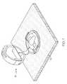
- FIG. 1is a perspective view of the two piece retainer assembly of the invention showing its installation on a section of floor mat with a hook-like fastener extending from a floor surface and through openings in the retainer assembly.
- FIG. 2is a perspective view of the two piece retainer assembly of FIG. 1 showing its cap in a closed position.
- FIG. 3is a perspective exploded view of the two piece retainer assembly of FIG. 1 in isolation.
- FIG. 4is a top plan view of the two piece assembly of FIG. 3 .
- the two piece retainer assembly of the inventionis particularly adapted for installation on a vehicle floor mat and for interacting with a hook-like fastener permanently secured to a floor of the vehicle. It can be used elsewhere, but finds its most popular use on vehicular floor mats and for this reason is described below in this context.
- FIG. 1there is shown in perspective a portion of a floor mat 10 and a hook-like fastener 11 .
- the floor matitself is conventional. It includes a molded thermoplastic backing and a carpet topside. While not apparent from the drawings, the floor mat 10 for use with the two piece retainer assembly of this invention further includes a hole extending fully through the carpet and the backing. The hole is near at least one corner of the floor mat positioned such that in use of the floor mat, the hole will be directly over the hook-like fastener.
- the hook-like fastener 11is permanently secured to a floor of the vehicle.
- a two piece retainer assembly 15is positioned in the hole of the floor mat 10 and permanently secured to it. It operates in association with the hook-like fastener 11 .
- the two piece retainer assembly 15 with is associated floor mat 10is positioned onto the hook-like fastener 11 . It is shown in an intermediate position.
- the two piece retainer assemblyis in a locked position which securely holds the floor mat to the hook-like fastener to prevent any significant lateral sliding of the floor mat.
- the two piece retainer assembly in the locked positionhas a low profile and does not itself interfere with use of the vehicle.
- the retainer assembly 15 of the inventionhas two pieces which are assembled on the floor mat to form an operable retention means which works in conjunction with the hook-like fastener on the vehicle's floor surface.
- the two piece retention assembly 15comprises an annular collar 16 and a locking cover coupler 17 .
- FIG. 4shows the annular collar 16 and the locking cover coupler 17 assembled together without the floor mat for illustration purposes only.
- the annular collar 16 of the two piece retainer assembly 15has a vertical upwardly extending wall 18 connected to a horizontal radially extending flange 19 .
- the flange 19extends from a lower terminus of the wall 18 .
- the wall 18 and the flange 19are integral, preferably molded as one piece.
- the wall 18 and flange 19could as well be manufactured separately and permanently secured together.
- the vertical upwardly extending wall 18forms an opening 20 for receiving the hook-like fastener 11 .
- the wall 18is continuous to form the closed opening 20 .
- the wall 18 as depictedis generally D-shaped with a straight leg 21 and a curved leg 22 joined to terminuses of the straight leg.
- the height of the wall 18is sufficiently high to accommodate the carpet thickness of the floor mat 10 .
- the shape and size of the opening formed by the vertical upwardly extending wallis determined in part by the degree of floor mat movement which can be tolerated.
- the openingcan be sized to receive the hook-like fastener with minimal clearance in order to achieve minimal floor mat movement.
- the vertical upwardly extending wall 18has at least one guide keyway 23 extending from an upper edge of the vertical wall downwardly.
- the wall 18has from two to four substantially equi-spaced keyways 23 .
- the annular collar 16also includes the horizontal radially extending flange 19 .
- the flangeextends outwardly from the vertical upwardly extending wall 18 . It forms a lip to contact the underside of floor mat 10 and provides a means of holding the annular collar 16 in proper position within the hole in the floor mat.
- the two piece retainer assembly 15also includes the locking cover coupler 17 .
- the coupler 17has a base plate 30 hinged to a cap 31 .
- the base plateis substantially flat with a top side and a bottom side. For appearance reasons, it is preferably generally circular.
- Recessed lands 32extend around the periphery of the top side of the base plate 30 to accommodate the cap as further discussed below. It also has recessed lands 33 and 34 extending across the base plate's upper surface and also for the purpose to accommodate the cap.
- the base platefurther has a set of latching tabs 35 extending vertically from the base plate's upper surface. As shown, the latching tabs 35 are opposed one another, though need not be. Each latching tab 35 includes a horizontal inwardly projecting ridge 36 at the latching tab's free end.
- a vertical downwardly extending wall 37extends from the bottom side of the base plate 30 .
- the wall 37is a continuous wall which forms an opening 38 .
- the wall 37makes frictional contact with the vertical upwardly extending wall 18 of the annular collar 16 .
- the vertical downwardly extending wall 37will necessarily also be generally D-shape.
- the generally D-shaped vertical downwardly extending wall 37is off-center. This creates a substantially flat platform 39 on the base plate 30 .
- a vertically extending leg of the hook-like fastener 11abuts against a straight leg of the D-shaped vertical downwardly extending wall 37 and the horizontally extending leg of the hook-like fastener 11 abuts against the substantially flat platform 39 for secure retention during use.
- the wall 37preferably fits within the wall 18 , though can also be sized to encompass the wall 18 .
- the wall 37accordingly has the same configuration as the wall 18 and is sized slightly less for the preferred embodiment.
- the vertical upwardly extending wall 18 of the annular collar 16 and the vertical downwardly extending wall 37 of the locking cover coupler 17are configured to fit into the floor mat hole and mate in frictional engagement to form a permanent retainer assembly on the floor mat.
- the vertical upwardly extending wall 18 of the base plate 30has aligned guide keys 40 .
- the keys 40are equal in 25 number and size to engage the keyways 23 of the wall 18 .
- the capprovides several important functions. When closed, it causes a locking wall to engage the hook-like fastener 11 extending through the opening 38 in the base plate to prevent movement of the floor mat 10 .
- the capalso seals off the underlying floor mat hole, thereby preventing water and debris from getting to the vehicle's floor surface. Further, the cap provides a smooth top surface as seen in FIG. 2 which is visually acceptable and can have a decorative value. It gives the retainer assembly a low profile, both enhancing the retainer assembly 15 functionally by lessening any driver interference and aesthetically by adding a finished appearance.
- the capis formed by a continuous wall 45 and a smooth flat surface 46 overlying the continuous wall.
- the continuous wall 45is preferably generally circular and configured to substantially fully overlie the base plate 30 .
- the wall 45 of the caphas two recessed slots 47 on an outer surface to receive the latching tabs. Each slot 47 includes a horizontal outwardly projecting ridge 48 .
- the projecting ridges 48receive the projecting ridges 36 on the latching tabs 35 and temporarily hold the cap to the base plate 30 when closed together.
- the capalso has an interior locking wall 49 extending across the hollow interior of the cap. It is positioned to contact the hook-like fastener when the cap is closed and frictionally hold the locking wall 49 to the hook-like fastener 11 .
- a support wall 50extends at a substantial right angle from a mid-section of the locking wall 49 to the exterior continuous wall 45 to add strength to the locking wall 49 .
- the recess lands 32 , 33 and 34 of the base plate 30receive the walls of the cap 31 so that the cap sits flush on the base plate 30 .
- the base plate 30 and cap 31are hinged together by a living hinge 52 .
- the locking cover coupleris molded as one piece with the living hinge 52 a part thereof.
- the base plate 30 and the cap 31can be separate components which are optionally hinged together.
- the capalso includes a pull tab 55 extending from the wall.
- the pull tab 55is to facilitate opening of the cap.
- the annular collar of the two piece retainer assemblyis positioned in a hole of the floor mat on the mat's underside.
- the locking cover coupleris then positioned on the top side of the floor mat's hole and the two pieces forced together until securely connected.
- the floor matcan now be slipped over the hook-like fastener in the floor of the vehicle and the floor mat straightened to lay properly on the floor. Closing the cap by forcing it downwardly forces the locking wall to engage the hook-like fastener.
- the floor matis now secured in place. It can subsequently be released from the hook-like fastener for cleaning or replacement purposes simply by raising the cap to release the cap's locking wall from engagement with the fastener.
Landscapes
- Engineering & Computer Science (AREA)
- Transportation (AREA)
- Mechanical Engineering (AREA)
- Passenger Equipment (AREA)
Abstract
Description
Claims (17)
Priority Applications (1)
| Application Number | Priority Date | Filing Date | Title |
|---|---|---|---|
| US09/758,277US6381806B1 (en) | 2001-01-12 | 2001-01-12 | Retainer assembly for positive retention of floor mat |
Applications Claiming Priority (1)
| Application Number | Priority Date | Filing Date | Title |
|---|---|---|---|
| US09/758,277US6381806B1 (en) | 2001-01-12 | 2001-01-12 | Retainer assembly for positive retention of floor mat |
Publications (1)
| Publication Number | Publication Date |
|---|---|
| US6381806B1true US6381806B1 (en) | 2002-05-07 |
Family
ID=25051171
Family Applications (1)
| Application Number | Title | Priority Date | Filing Date |
|---|---|---|---|
| US09/758,277Expired - Fee RelatedUS6381806B1 (en) | 2001-01-12 | 2001-01-12 | Retainer assembly for positive retention of floor mat |
Country Status (1)
| Country | Link |
|---|---|
| US (1) | US6381806B1 (en) |
Cited By (35)
| Publication number | Priority date | Publication date | Assignee | Title |
|---|---|---|---|---|
| US6757945B2 (en)* | 2000-12-27 | 2004-07-06 | Newfrey Llc | Mat fastener |
| US20050039308A1 (en)* | 2003-08-21 | 2005-02-24 | Rogers James Ray | Removable hat accessory |
| US20050079318A1 (en)* | 2003-09-03 | 2005-04-14 | Maureen Putt | Vehicle floor mats having integral hook retention |
| US20060226312A1 (en)* | 2003-11-15 | 2006-10-12 | Frank Masuch | Device for connecting two components at a distance apart from one another |
| US20070123879A1 (en)* | 2003-02-05 | 2007-05-31 | Pioneer Laboratories, Inc. | Bone plate system |
| US20070257506A1 (en)* | 2006-05-04 | 2007-11-08 | Kenny Kevin B | Apparatus for fastening an object |
| US7465135B2 (en)* | 2003-11-14 | 2008-12-16 | Maclean-Fogg Company | U-Nut fastening assembly |
| US20090012571A1 (en)* | 2007-07-03 | 2009-01-08 | Pioneer Surgical Technology, Inc. | Bone Plate System |
| US20090007371A1 (en)* | 2007-07-05 | 2009-01-08 | Connor Jr Mark A | Floor mat clip assembly |
| US20090062862A1 (en)* | 2007-07-03 | 2009-03-05 | Pioneer Surgical Technology, Inc. | Bone Plate System |
| US20090235485A1 (en)* | 2007-07-05 | 2009-09-24 | Connor Jr Mark A | Floor mat clip assembly |
| US20100122429A1 (en)* | 2008-11-14 | 2010-05-20 | International Automotive Components Group North America, Inc | Three piece floor mat retention system |
| US7740649B2 (en) | 2004-02-26 | 2010-06-22 | Pioneer Surgical Technology, Inc. | Bone plate system and methods |
| US20100212119A1 (en)* | 2009-02-25 | 2010-08-26 | Newfrey Llc | Fastening assembly for securing floor mat to carpet |
| US20100223762A1 (en)* | 2003-08-21 | 2010-09-09 | Rogers James R | Removable hat accessory |
| WO2013163514A3 (en)* | 2012-04-27 | 2014-01-03 | Macneil Ip Llc | Two-piece vehicle floor cover retention device |
| US8851551B1 (en) | 2013-06-12 | 2014-10-07 | Macneil Ip Llc | Vehicle floor cover retention system and device |
| US8900277B2 (en) | 2004-02-26 | 2014-12-02 | Pioneer Surgical Technology, Inc. | Bone plate system |
| USD721629S1 (en) | 2013-05-30 | 2015-01-27 | Macneil Ip Llc | Vehicle floor cover retention post attachment device |
| US20150086295A1 (en)* | 2013-09-23 | 2015-03-26 | The Boeing Company | Systems and methods for use in covering a portion of a fastener protruding from a surface |
| US9199567B1 (en) | 2015-03-27 | 2015-12-01 | Macneil Ip Llc | Vehicle floor cover retention device with spiked base |
| US20160185306A1 (en)* | 2014-12-31 | 2016-06-30 | Ricardo Hernandez de Luna | Locking bar mechanism license plates |
| WO2016104143A1 (en)* | 2014-12-26 | 2016-06-30 | 株式会社ホンダアクセス | Affixation structure for vehicular floor mat, and structure for affixation to member |
| US9541118B2 (en) | 2013-09-23 | 2017-01-10 | The Boeing Company | Systems and methods for use in covering a portion of a fastener protruding from a surface |
| US9610880B2 (en) | 2015-07-29 | 2017-04-04 | Macneil Ip Llc | Multi-vehicle retention grommet |
| US10011207B2 (en) | 2015-07-29 | 2018-07-03 | Macneil Ip Llc | Vehicle floor mat with watertight capped grommets |
| US10322657B2 (en)* | 2017-07-25 | 2019-06-18 | Ford Global Technologies, Llc | Clip assembly for all-weather mats |
| US10493890B2 (en) | 2016-09-06 | 2019-12-03 | Ford Global Technologies Llc | Fasteners for a vehicle carpet |
| US10823211B2 (en)* | 2017-02-10 | 2020-11-03 | Hanwit Precision Industries Ltd. | Floating fastener |
| US10946781B2 (en)* | 2019-04-11 | 2021-03-16 | GM Global Technology Operations LLC | Vehicle floor mat retainer |
| US20220333635A1 (en)* | 2021-04-20 | 2022-10-20 | National Nail Corp. | Sealed fastener cap and related method of manufacture |
| US11519441B2 (en)* | 2019-01-10 | 2022-12-06 | Illinois Tool Works Inc. | Tree fastener removal assemblies and methods therefor |
| US11642996B2 (en) | 2021-10-07 | 2023-05-09 | Tarboy LLC | Vehicle floor covering system |
| US11877779B2 (en) | 2020-03-26 | 2024-01-23 | Xtant Medical Holdings, Inc. | Bone plate system |
| EP4030068B1 (en)* | 2021-01-18 | 2024-12-04 | Illinois Tool Works Inc. | Verification cap |
Citations (17)
| Publication number | Priority date | Publication date | Assignee | Title |
|---|---|---|---|---|
| US1691013A (en) | 1924-12-20 | 1928-11-06 | Carr Fastener Co Ltd | Separable fastener |
| US1766204A (en) | 1928-05-11 | 1930-06-24 | Waldes Jindrich | Button |
| US2109402A (en) | 1934-05-12 | 1938-02-22 | George E Gagnier | Carpet fastener |
| US2210799A (en) | 1939-06-07 | 1940-08-06 | Charles M Denny | Tieback fastener |
| US4214505A (en)* | 1977-09-26 | 1980-07-29 | Itw Fastex Italia S.P.A. | Bush for anchoring panel fasteners |
| US4358874A (en) | 1980-10-31 | 1982-11-16 | Motorola, Inc. | Retaining device |
| US4392279A (en) | 1981-09-14 | 1983-07-12 | Mattel, Inc. | Self-locking two-part fastener |
| US4406033A (en) | 1981-07-23 | 1983-09-27 | Illinois Tool Works Inc. | Fastener for attachment of a continuous article to a support |
| US4561146A (en) | 1983-10-06 | 1985-12-31 | Usm Corporation | Plastic fastener |
| US4829627A (en) | 1987-10-15 | 1989-05-16 | The 2500 Corporation | Floor mat and method of attaching retainer thereto |
| US4918791A (en) | 1989-03-06 | 1990-04-24 | Hardin James A | Clothing button guard |
| US5332347A (en)* | 1992-06-10 | 1994-07-26 | Nifco, Inc. | Mat fastener |
| US5621951A (en) | 1996-06-17 | 1997-04-22 | Gould; John C. | Device for covering and concealing buttons |
| US5666691A (en) | 1995-09-20 | 1997-09-16 | Lear Corporation | Method of attaching insulation to molded automotive floors |
| US5775859A (en) | 1997-06-06 | 1998-07-07 | National Molding Corp. | Mat fastener |
| US6009562A (en) | 1998-08-26 | 2000-01-04 | Bell Sports, Inc. | Helmet with accessory mounting apparatus and method of making the same |
| US6264413B1 (en)* | 1999-04-26 | 2001-07-24 | Hilti Aktiengesellschaft | Fastening element for attaching insulation boards |
- 2001
- 2001-01-12USUS09/758,277patent/US6381806B1/ennot_activeExpired - Fee Related
Patent Citations (17)
| Publication number | Priority date | Publication date | Assignee | Title |
|---|---|---|---|---|
| US1691013A (en) | 1924-12-20 | 1928-11-06 | Carr Fastener Co Ltd | Separable fastener |
| US1766204A (en) | 1928-05-11 | 1930-06-24 | Waldes Jindrich | Button |
| US2109402A (en) | 1934-05-12 | 1938-02-22 | George E Gagnier | Carpet fastener |
| US2210799A (en) | 1939-06-07 | 1940-08-06 | Charles M Denny | Tieback fastener |
| US4214505A (en)* | 1977-09-26 | 1980-07-29 | Itw Fastex Italia S.P.A. | Bush for anchoring panel fasteners |
| US4358874A (en) | 1980-10-31 | 1982-11-16 | Motorola, Inc. | Retaining device |
| US4406033A (en) | 1981-07-23 | 1983-09-27 | Illinois Tool Works Inc. | Fastener for attachment of a continuous article to a support |
| US4392279A (en) | 1981-09-14 | 1983-07-12 | Mattel, Inc. | Self-locking two-part fastener |
| US4561146A (en) | 1983-10-06 | 1985-12-31 | Usm Corporation | Plastic fastener |
| US4829627A (en) | 1987-10-15 | 1989-05-16 | The 2500 Corporation | Floor mat and method of attaching retainer thereto |
| US4918791A (en) | 1989-03-06 | 1990-04-24 | Hardin James A | Clothing button guard |
| US5332347A (en)* | 1992-06-10 | 1994-07-26 | Nifco, Inc. | Mat fastener |
| US5666691A (en) | 1995-09-20 | 1997-09-16 | Lear Corporation | Method of attaching insulation to molded automotive floors |
| US5621951A (en) | 1996-06-17 | 1997-04-22 | Gould; John C. | Device for covering and concealing buttons |
| US5775859A (en) | 1997-06-06 | 1998-07-07 | National Molding Corp. | Mat fastener |
| US6009562A (en) | 1998-08-26 | 2000-01-04 | Bell Sports, Inc. | Helmet with accessory mounting apparatus and method of making the same |
| US6264413B1 (en)* | 1999-04-26 | 2001-07-24 | Hilti Aktiengesellschaft | Fastening element for attaching insulation boards |
Cited By (67)
| Publication number | Priority date | Publication date | Assignee | Title |
|---|---|---|---|---|
| US6757945B2 (en)* | 2000-12-27 | 2004-07-06 | Newfrey Llc | Mat fastener |
| US20070123879A1 (en)* | 2003-02-05 | 2007-05-31 | Pioneer Laboratories, Inc. | Bone plate system |
| US8172885B2 (en) | 2003-02-05 | 2012-05-08 | Pioneer Surgical Technology, Inc. | Bone plate system |
| US20100223762A1 (en)* | 2003-08-21 | 2010-09-09 | Rogers James R | Removable hat accessory |
| US20050039308A1 (en)* | 2003-08-21 | 2005-02-24 | Rogers James Ray | Removable hat accessory |
| US7350274B2 (en)* | 2003-08-21 | 2008-04-01 | Namkung Promotions, Inc. | Removable hat accessory |
| US20050079318A1 (en)* | 2003-09-03 | 2005-04-14 | Maureen Putt | Vehicle floor mats having integral hook retention |
| US7329451B2 (en)* | 2003-09-03 | 2008-02-12 | International Automotive Components Group North America, Inc. | Vehicle floor mats having integral hook retention |
| US7465135B2 (en)* | 2003-11-14 | 2008-12-16 | Maclean-Fogg Company | U-Nut fastening assembly |
| US20060226312A1 (en)* | 2003-11-15 | 2006-10-12 | Frank Masuch | Device for connecting two components at a distance apart from one another |
| US8900277B2 (en) | 2004-02-26 | 2014-12-02 | Pioneer Surgical Technology, Inc. | Bone plate system |
| US7740649B2 (en) | 2004-02-26 | 2010-06-22 | Pioneer Surgical Technology, Inc. | Bone plate system and methods |
| US10166051B2 (en) | 2004-02-26 | 2019-01-01 | Pioneer Surgical Technology, Inc. | Bone plate system |
| US11129653B2 (en) | 2004-02-26 | 2021-09-28 | Pioneer Surgical Technology, Inc. | Bone plate system |
| US20070257506A1 (en)* | 2006-05-04 | 2007-11-08 | Kenny Kevin B | Apparatus for fastening an object |
| WO2007131008A3 (en)* | 2006-05-04 | 2008-01-03 | Shell Oil Co | Apparatus for fastening an object |
| US20090012571A1 (en)* | 2007-07-03 | 2009-01-08 | Pioneer Surgical Technology, Inc. | Bone Plate System |
| US8623019B2 (en) | 2007-07-03 | 2014-01-07 | Pioneer Surgical Technology, Inc. | Bone plate system |
| US20090062862A1 (en)* | 2007-07-03 | 2009-03-05 | Pioneer Surgical Technology, Inc. | Bone Plate System |
| US10898247B2 (en) | 2007-07-03 | 2021-01-26 | Pioneer Surgical Technology, Inc. | Bone plate system |
| US9381046B2 (en) | 2007-07-03 | 2016-07-05 | Pioneer Surgical Technology, Inc. | Bone plate system |
| US8361126B2 (en) | 2007-07-03 | 2013-01-29 | Pioneer Surgical Technology, Inc. | Bone plate system |
| US10226291B2 (en) | 2007-07-03 | 2019-03-12 | Pioneer Surgical Technology, Inc. | Bone plate system |
| US9655665B2 (en) | 2007-07-03 | 2017-05-23 | Pioneer Surgical Technology, Inc. | Bone plate systems |
| US20090235485A1 (en)* | 2007-07-05 | 2009-09-24 | Connor Jr Mark A | Floor mat clip assembly |
| US7546661B2 (en)* | 2007-07-05 | 2009-06-16 | Connor Jr Mark A | Floor mat clip assembly |
| US8122567B2 (en) | 2007-07-05 | 2012-02-28 | Connor Jr Mark A | Floor mat clip assembly |
| US20090007371A1 (en)* | 2007-07-05 | 2009-01-08 | Connor Jr Mark A | Floor mat clip assembly |
| US20140215802A1 (en)* | 2008-11-14 | 2014-08-07 | International Automotive Components Group North America, Inc. | Three piece floor mat retention system |
| US20100122429A1 (en)* | 2008-11-14 | 2010-05-20 | International Automotive Components Group North America, Inc | Three piece floor mat retention system |
| US8931162B2 (en)* | 2008-11-14 | 2015-01-13 | International Automotive Components Group North America, Inc. | Three piece floor mat retention system |
| US20130125341A1 (en)* | 2009-02-25 | 2013-05-23 | Newfrey Llc | Fastening assembly for securing floor mat to carpet |
| US8375514B2 (en)* | 2009-02-25 | 2013-02-19 | Newfrey Llc | Fastening assembly for securing floor mat to carpet |
| US8756758B2 (en)* | 2009-02-25 | 2014-06-24 | Newfrey Llc | Fastening assembly for securing floor mat to carpet |
| US20100212119A1 (en)* | 2009-02-25 | 2010-08-26 | Newfrey Llc | Fastening assembly for securing floor mat to carpet |
| KR20140126386A (en)* | 2012-04-27 | 2014-10-30 | 맥닐 아이피 엘엘씨 | Two-piece vehicle floor cover retention device |
| AU2013251477B2 (en)* | 2012-04-27 | 2015-10-08 | Macneil Ip Llc | Two-piece vehicle floor cover retention device |
| KR101590744B1 (en)* | 2012-04-27 | 2016-02-01 | 맥닐 아이피 엘엘씨 | Two-piece vehicle floor cover retention device |
| US9340137B2 (en) | 2012-04-27 | 2016-05-17 | Macneil Ip Llc | Vehicle floor cover affixation system |
| US9340136B2 (en) | 2012-04-27 | 2016-05-17 | Macneil Ip Llc | Two-piece vehicle floor cover retention device |
| US8991006B2 (en) | 2012-04-27 | 2015-03-31 | Macneil Ip Llc | Two-piece vehicle floor cover retention device |
| WO2013163514A3 (en)* | 2012-04-27 | 2014-01-03 | Macneil Ip Llc | Two-piece vehicle floor cover retention device |
| USD721629S1 (en) | 2013-05-30 | 2015-01-27 | Macneil Ip Llc | Vehicle floor cover retention post attachment device |
| US8851551B1 (en) | 2013-06-12 | 2014-10-07 | Macneil Ip Llc | Vehicle floor cover retention system and device |
| US10495132B2 (en) | 2013-09-23 | 2019-12-03 | The Boeing Company | Methods for use in covering a portion of a fastener protruding from a surface |
| US11149780B2 (en) | 2013-09-23 | 2021-10-19 | The Boeing Company | Method of covering a portion of a fastener protruding from a surface |
| US9618029B2 (en)* | 2013-09-23 | 2017-04-11 | The Boeing Company | Systems and methods for use in covering a portion of a fastener protruding from a surface |
| US9541118B2 (en) | 2013-09-23 | 2017-01-10 | The Boeing Company | Systems and methods for use in covering a portion of a fastener protruding from a surface |
| US10233961B2 (en) | 2013-09-23 | 2019-03-19 | The Boeing Company | Methods for covering a portion of a fastener protruding from a surface |
| US20150086295A1 (en)* | 2013-09-23 | 2015-03-26 | The Boeing Company | Systems and methods for use in covering a portion of a fastener protruding from a surface |
| WO2016104143A1 (en)* | 2014-12-26 | 2016-06-30 | 株式会社ホンダアクセス | Affixation structure for vehicular floor mat, and structure for affixation to member |
| JPWO2016104143A1 (en)* | 2014-12-26 | 2017-09-07 | 株式会社ホンダアクセス | Fixing structure of vehicle floor mat and fixing structure to member |
| US9663044B2 (en)* | 2014-12-31 | 2017-05-30 | Ricardo Hernandez de Luna | Locking bar mechanism license plates |
| US20160185306A1 (en)* | 2014-12-31 | 2016-06-30 | Ricardo Hernandez de Luna | Locking bar mechanism license plates |
| US9199567B1 (en) | 2015-03-27 | 2015-12-01 | Macneil Ip Llc | Vehicle floor cover retention device with spiked base |
| US10011207B2 (en) | 2015-07-29 | 2018-07-03 | Macneil Ip Llc | Vehicle floor mat with watertight capped grommets |
| US9610880B2 (en) | 2015-07-29 | 2017-04-04 | Macneil Ip Llc | Multi-vehicle retention grommet |
| US10493890B2 (en) | 2016-09-06 | 2019-12-03 | Ford Global Technologies Llc | Fasteners for a vehicle carpet |
| US10823211B2 (en)* | 2017-02-10 | 2020-11-03 | Hanwit Precision Industries Ltd. | Floating fastener |
| US10322657B2 (en)* | 2017-07-25 | 2019-06-18 | Ford Global Technologies, Llc | Clip assembly for all-weather mats |
| US11519441B2 (en)* | 2019-01-10 | 2022-12-06 | Illinois Tool Works Inc. | Tree fastener removal assemblies and methods therefor |
| US10946781B2 (en)* | 2019-04-11 | 2021-03-16 | GM Global Technology Operations LLC | Vehicle floor mat retainer |
| US11877779B2 (en) | 2020-03-26 | 2024-01-23 | Xtant Medical Holdings, Inc. | Bone plate system |
| EP4030068B1 (en)* | 2021-01-18 | 2024-12-04 | Illinois Tool Works Inc. | Verification cap |
| US20220333635A1 (en)* | 2021-04-20 | 2022-10-20 | National Nail Corp. | Sealed fastener cap and related method of manufacture |
| US11674544B2 (en)* | 2021-04-20 | 2023-06-13 | National Nail Corp. | Sealed fastener cap and related method of manufacture |
| US11642996B2 (en) | 2021-10-07 | 2023-05-09 | Tarboy LLC | Vehicle floor covering system |
Similar Documents
| Publication | Publication Date | Title |
|---|---|---|
| US6381806B1 (en) | Retainer assembly for positive retention of floor mat | |
| CN1966309B (en) | hook attachment unit | |
| JPH0246197Y2 (en) | ||
| EP0053923B1 (en) | Seat track fitting | |
| US8851551B1 (en) | Vehicle floor cover retention system and device | |
| JP2896887B2 (en) | Mat fastening device | |
| USRE41624E1 (en) | Locking bracket and cupholder for seat frame | |
| US5673956A (en) | Bedliner with floor hole engagement | |
| US5639140A (en) | Hook retainer for a vehicle trim panel | |
| US20140215802A1 (en) | Three piece floor mat retention system | |
| US5094092A (en) | Auto vehicle pedal lock | |
| US6382675B1 (en) | Attaching structure for wheel house cover | |
| US5364150A (en) | Truck bedliner locking device | |
| US4527835A (en) | Seat belt sleeve | |
| JP4098518B2 (en) | Floor covering for powered vehicles | |
| US11155189B2 (en) | Bumper assembly for vehicle seat | |
| US20040108320A1 (en) | Trash can plug | |
| JPH0127468Y2 (en) | ||
| KR101477924B1 (en) | Fixing device of auxiliary mat automobile | |
| US5090777A (en) | Automobile wheel cover | |
| KR100559049B1 (en) | Car Assist Mat Hook | |
| JP2808903B2 (en) | Fixture for floor mat | |
| US6726268B2 (en) | Restraint mechanism for floor mat | |
| JPS6213886Y2 (en) | ||
| US20070273163A1 (en) | Door handle system |
Legal Events
| Date | Code | Title | Description |
|---|---|---|---|
| AS | Assignment | Owner name:NIFTY PRODUCTS, INC., OHIO Free format text:ASSIGNMENT OF ASSIGNORS INTEREST;ASSIGNORS:STANESIC, J. MATTHEW;SHERMAN, RAYMOND O.;REEL/FRAME:012742/0060 Effective date:20010105 | |
| FEPP | Fee payment procedure | Free format text:PAT HOLDER NO LONGER CLAIMS SMALL ENTITY STATUS, ENTITY STATUS SET TO UNDISCOUNTED (ORIGINAL EVENT CODE: STOL); ENTITY STATUS OF PATENT OWNER: LARGE ENTITY | |
| REFU | Refund | Free format text:REFUND - SURCHARGE, PETITION TO ACCEPT PYMT AFTER EXP, UNINTENTIONAL (ORIGINAL EVENT CODE: R2551); ENTITY STATUS OF PATENT OWNER: LARGE ENTITY | |
| FPAY | Fee payment | Year of fee payment:4 | |
| FEPP | Fee payment procedure | Free format text:PAYOR NUMBER ASSIGNED (ORIGINAL EVENT CODE: ASPN); ENTITY STATUS OF PATENT OWNER: LARGE ENTITY | |
| AS | Assignment | Owner name:DEFLECTA-SHIELD CORPORATION, GEORGIA Free format text:ASSIGNMENT OF ASSIGNORS INTEREST;ASSIGNOR:NIFTY PRODUCTS, INC.;REEL/FRAME:018904/0369 Effective date:20021118 Owner name:LUND INTERNATIONAL, INC., MINNESOTA Free format text:MERGER;ASSIGNORS:AUTO VENTSHADE COMPANY;DEFLECTA-SHIELD CORPORATION;LUND INTERNATIONAL, INC.;REEL/FRAME:018904/0379 Effective date:20030227 | |
| AS | Assignment | Owner name:LUND INTERNATIONAL HOLDINGS, INC., GEORGIA Free format text:BANKRUPTCY COURT ORDER AND ASSET PURCHASE AGREEMENT;ASSIGNOR:NIFTY PRODUCTS, INC.;REEL/FRAME:020166/0352 Effective date:20021022 | |
| AS | Assignment | Owner name:LUND, INC., GEORGIA Free format text:ASSIGNMENT OF ASSIGNORS INTEREST;ASSIGNORS:LUND INTERNATIONAL HOLDINGS, INC.;LUND INTERNATIONAL, INC.;REEL/FRAME:020317/0743 Effective date:20071129 | |
| AS | Assignment | Owner name:GENERAL ELECTRIC CAPITAL CORPORATION, AS ADMINISTR Free format text:SECURITY AGREEMENT;ASSIGNOR:LUND, INC.;REEL/FRAME:020403/0930 Effective date:20071130 | |
| REMI | Maintenance fee reminder mailed | ||
| LAPS | Lapse for failure to pay maintenance fees | ||
| STCH | Information on status: patent discontinuation | Free format text:PATENT EXPIRED DUE TO NONPAYMENT OF MAINTENANCE FEES UNDER 37 CFR 1.362 | |
| FP | Lapsed due to failure to pay maintenance fee | Effective date:20100507 | |
| AS | Assignment | Owner name:LUND INTERNATINAL, INC., GEORGIA Free format text:RELEASE BY SECURED PARTY;ASSIGNOR:GENERAL ELECTRIC CAPITAL CORPORATION;REEL/FRAME:026205/0422 Effective date:20110427 Owner name:BELMOR, INC., GEORGIA Free format text:RELEASE BY SECURED PARTY;ASSIGNOR:GENERAL ELECTRIC CAPITAL CORPORATION;REEL/FRAME:026205/0422 Effective date:20110427 Owner name:LUND, INC., GEORGIA Free format text:RELEASE BY SECURED PARTY;ASSIGNOR:GENERAL ELECTRIC CAPITAL CORPORATION;REEL/FRAME:026205/0422 Effective date:20110427 |