US6381135B1 - Loop heat pipe for mobile computers - Google Patents
Loop heat pipe for mobile computersDownload PDFInfo
- Publication number
- US6381135B1 US6381135B1US09/814,078US81407801AUS6381135B1US 6381135 B1US6381135 B1US 6381135B1US 81407801 AUS81407801 AUS 81407801AUS 6381135 B1US6381135 B1US 6381135B1
- Authority
- US
- United States
- Prior art keywords
- wick structure
- evaporator
- wick
- condenser
- die
- Prior art date
- Legal status (The legal status is an assumption and is not a legal conclusion. Google has not performed a legal analysis and makes no representation as to the accuracy of the status listed.)
- Expired - Lifetime
Links
Images


Classifications
- F—MECHANICAL ENGINEERING; LIGHTING; HEATING; WEAPONS; BLASTING
- F28—HEAT EXCHANGE IN GENERAL
- F28D—HEAT-EXCHANGE APPARATUS, NOT PROVIDED FOR IN ANOTHER SUBCLASS, IN WHICH THE HEAT-EXCHANGE MEDIA DO NOT COME INTO DIRECT CONTACT
- F28D15/00—Heat-exchange apparatus with the intermediate heat-transfer medium in closed tubes passing into or through the conduit walls ; Heat-exchange apparatus employing intermediate heat-transfer medium or bodies
- F28D15/02—Heat-exchange apparatus with the intermediate heat-transfer medium in closed tubes passing into or through the conduit walls ; Heat-exchange apparatus employing intermediate heat-transfer medium or bodies in which the medium condenses and evaporates, e.g. heat pipes
- F28D15/04—Heat-exchange apparatus with the intermediate heat-transfer medium in closed tubes passing into or through the conduit walls ; Heat-exchange apparatus employing intermediate heat-transfer medium or bodies in which the medium condenses and evaporates, e.g. heat pipes with tubes having a capillary structure
- F28D15/043—Heat-exchange apparatus with the intermediate heat-transfer medium in closed tubes passing into or through the conduit walls ; Heat-exchange apparatus employing intermediate heat-transfer medium or bodies in which the medium condenses and evaporates, e.g. heat pipes with tubes having a capillary structure forming loops, e.g. capillary pumped loops
Definitions
- This inventionrelates generally to heat removal in computer systems, and more specifically, to an improved heat removal device for mobile computing systems.
- FIGS. 1A and 1Bshow a front view and a side view, respectively, of a typical heat transfer system used in mobile computing applications.
- the heat transfer system 100 A shown in FIG. 1Aincludes a substrate 102 A with a die 104 A sitting on top of the substrate 102 A.
- Die 104 Ais typically made of silicon and contains the electronic components of the microprocessor.
- Heatis generated in die 104 A and passed through thermal interface material (TIM) 106 A to a heat spreader 108 A.
- Heat spreader 108 Ais typically larger than the die 104 A.
- the TIM 106 Areduces the contact resistance between the die 104 A and the heat spreader 108 A.
- the Tim 106 Amay be solder, a particle-laden polymer, or other material exhibiting similar thermal properties.
- Heat spreader 108 Ais typically a copper block and is soldered to heat pipe 112 A with a solder layer 110 A. Embedded in heat pipe 112 A is a wick structure 114 A and a vapor space 116 A that contains vapor. The walls of the heat pipe are typically copper. The heat generated in the die 104 A is used to heat the liquid in the vapor space to convert it to a vapor. The vapor then condenses when heat is drawn through the heat sink 118 B depicted in FIG. 1 B. The heat sink 118 B is typically a copper or aluminum block that may have fins to dissipate the heat more quickly.
- the wick structure 114 Aworks as a capillary pump that brings the condensed liquid back to the heating region thereby maintaining a continuous loop.
- This cooling methodis known as remote cooling because the heat is not ejected at the location of the die, but is transferred elsewhere and ejected.
- the heat sinkcan be placed directly on top of the die, but for mobile applications a thinner implementation is desired.
- Another reason remote cooling is desired in mobile applicationsis that it allows for the heat sink to be located next to an exhaust fan typically located in a corner of the laptop. This allows the heat to be carried out of the mobile system quickly.
- the prior art heat transfer systempresents several problems concerning wick structure 114 A.
- the firstis due to the fabrication process used to create the wick structure 114 A.
- a wick structureis made of porous copper.
- the wick structureis fabricated by sprinkling powdered copper along the inner length of the heat pipe. The powdered copper is then heated and slightly melted. This forms a porous copper structure. This process is not exact, and the wick structure 114 A typically has large variations in its thickness along the length of the heat pipe. Because the vapor space 116 A is a space above the wick structure 114 A, variations in the thickness of the wick structure 114 A cause corresponding variations in the thickness of the vapor space.
- the thermal resistanceis inversely proportional to the 4 th power of the vapor space thickness or radius. Therefore small variations in the thickness of the vapor space 116 cause large variations in the thermal resistance.
- Another problem with the prior art heat transfer system 100 Ais in the component layout.
- the fanis located in the corner and the processor is located somewhere else. Since it is desirable to have the heat sink next to the fan, the heat pipe may have to be twisted and bent to accommodate component layout. This twisting and bending can also lead to variations in the thickness of the wick structure and therefore variations in the vapor space.
- Another drawbackis that the current fabrication process provides one wick structure for all areas of the heat transfer process. Ideally, to enhance the performance of a heat pipe, it is desired to have wick structure with variable porosity so that the evaporative and the condenser section have highly porous wick structures to enhance the boiling and condensation heat transfer and the adiabatic section has a different wick structure for optimized pressure drop.
- the current manufacturing technology of heat pipesdoes not allow this.
- Performance of current heat pipe technologyalso suffers from the variation in the weight of wick and in water charge level.
- FIG. 1shows a typical heat transfer system used in mobile computing applications according to the prior art
- FIG. 2shows a loop heat pipe for mobile computing systems according to the present invention.
- FIG. 3shows three exemplary wick structures, 3 a , 3 b , and 3 c , for use with the present invention.
- a heat transfer device for a mobile computer systemis provided.
- a loop heat pipeis used, with the evaporator of the loop heat pipe coupled to the processor die.
- the vapor space and liquid spaceare separated. This allows the vapor to reach the condenser though the vapor space and the liquid to return to the evaporator through the wick structure of the liquid space, with no interaction between the liquid and the vapor in the adiabatic section.
- the separation of the vapor space, and the wick structure of the liquid spaceensures that the vapor space will not be distorted or clogged by the wick structure. This provides greater layout flexibility as the heat transfer device can be bent to meet design criteria without distorting the width or radius of the vapor space.
- the evaporator, condenser, and liquid spacehave different types of wick structure.
- a loop heat pipe device for a mobile computer systemhaving a vapor space of uniform thickness.
- Another embodiment of the present inventionprovides a loop heat pipe device having an evaporator attached to the die with no solder layer. This is very beneficial as solder is a high thermal resistance material.
- the loop heat pipe device of the present inventionprovides reduced evaporator and condenser resistance and increased burn out flux, thereby increasing the power handling capacity of the device.
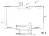
- FIG. 2shows a loop heat pipe for mobile computing systems according to the present invention.
- the loop heat pipe 200 shown in FIG. 2has a substrate 202 with a die 204 on top of the substrate 202 .
- TIM layer 206is between the die and the evaporator 212 .
- the absence of the solder layer of the prior artis very beneficial as solder is a high thermal resistance material.
- the evaporator 212is a hollow copper block that also acts as a heat spreader.
- the evaporator 212is placed on the die with only the TIM layer 206 between them.
- the evaporatorcontains a wick structure 213 that adjoins the liquid space 214 on one side.
- Liquid space 214also contains a wick structure, however the wick structure of the liquid space 214 and wick structure 213 of the evaporator need not be the same type of wick structure.
- the different wick structurescould be fabricated using the powdered copper method as discussed above only with a different porosity, or could be wick structures fabricated in some other way (e.g., wire mesh wick).
- the ability to implement different wick structures at different areas of the heat pipeis beneficial as it is desirable that the evaporator wick structure has low thermal resistance. Thermal resistance is not as important a consideration for the liquid space wick structure.
- the pumping capacityaffects the maximum power handling capacity of the heat pipe.
- the ability to use two different types of wick structure at different places in the heat pipeenhances the design flexibility and overall performance characteristics of the heat pipe.
- vapor space 216Adjoining the wick structure 213 , on the other side, is vapor space 216 .
- the vapor space 216is no longer in direct contact with the wick structure of the liquid space. Variations of the wick structure thickness no longer affect the vapor space.
- Vapor space 216is simply a hollow tube. The thickness or radius of the vapor space can, therefore, be highly controlled and will be highly uniform. Having the vapor space separate from the liquid space wick structure produces a vapor space that is highly insensitive to manufacturing tolerances and variation in the amount of wick and water charge level.
- Condenser 218is a hollow block of copper, or some thermally similar metal (e.g., aluminum). In one embodiment condenser 218 has fins attached to dissipate heat. In another embodiment fins may be placed along the vapor space wall.
- the condenser 218has a wick structure 219 as well that may be different than the wick structure 213 or the wick structure of the liquid space. As discussed above, there may be design considerations that indicate one wick structure as opposed to another.
- a condenser wick with low thermal resistancemay not be necessary. This is the case where the condenser is much larger than the evaporator. If the condenser is smaller than the evaporator, a condenser wick with low thermal resistance is called for.
- FIG. 3shows three exemplary types of wick structure, 3 a , 3 b , and 3 c , for use with the present invention
- the wick structure 301 shown in FIG. 3 ais a circular artery type wick structure for use, for example, in the evaporator 213 .
- FIG. 3 bshows a square wire mesh screen type wick structure 302
- FIG. 3 cshows an unconsolidated packed spherical particle type wick structure 303 .
- the square wire mesh screen type wick structure and the packed spherical particle type wick structurehave higher pumping capacity and are better for use as wick structures for liquid space 214 .
- the condenser and the evaporatorhave highly porous wick structures. Having highly porous wick structures in the evaporator and the condenser can substantially reduce the evaporative and condenser thermal resistance, which is very desirable for high wattage applications. Also, having highly porous wick structures in the evaporator and the condenser provides higher burn out flux. For a non-uniformly heated die the flux could be very high. This will enable heat pipes to be used for high flux processors.
Landscapes
- Engineering & Computer Science (AREA)
- Life Sciences & Earth Sciences (AREA)
- Sustainable Development (AREA)
- Physics & Mathematics (AREA)
- Thermal Sciences (AREA)
- Mechanical Engineering (AREA)
- General Engineering & Computer Science (AREA)
- Cooling Or The Like Of Electrical Apparatus (AREA)
- Cooling Or The Like Of Semiconductors Or Solid State Devices (AREA)
Abstract
Description
This invention relates generally to heat removal in computer systems, and more specifically, to an improved heat removal device for mobile computing systems.
As mobile computing systems (e.g., laptops) become smaller and smaller, the need for design flexibility increases. The power level of laptop processors is increasing with a corresponding increase in heat that must be removed from the system.
FIGS. 1A and 1B show a front view and a side view, respectively, of a typical heat transfer system used in mobile computing applications. Theheat transfer system 100A shown in FIG. 1A, includes asubstrate 102A with adie 104A sitting on top of thesubstrate 102A. Die104A is typically made of silicon and contains the electronic components of the microprocessor. Heat is generated in die104A and passed through thermal interface material (TIM)106A to aheat spreader 108A.Heat spreader 108A is typically larger than the die104A. The TIM106A reduces the contact resistance between the die104A and theheat spreader 108A. The Tim106A may be solder, a particle-laden polymer, or other material exhibiting similar thermal properties.Heat spreader 108A is typically a copper block and is soldered toheat pipe 112A with asolder layer 110A. Embedded inheat pipe 112A is a wick structure114A and avapor space 116A that contains vapor. The walls of the heat pipe are typically copper. The heat generated in thedie 104A is used to heat the liquid in the vapor space to convert it to a vapor. The vapor then condenses when heat is drawn through theheat sink 118B depicted in FIG.1B. Theheat sink 118B is typically a copper or aluminum block that may have fins to dissipate the heat more quickly. The wick structure114A works as a capillary pump that brings the condensed liquid back to the heating region thereby maintaining a continuous loop.
This cooling method is known as remote cooling because the heat is not ejected at the location of the die, but is transferred elsewhere and ejected. In a typical desktop computer the heat sink can be placed directly on top of the die, but for mobile applications a thinner implementation is desired. Another reason remote cooling is desired in mobile applications is that it allows for the heat sink to be located next to an exhaust fan typically located in a corner of the laptop. This allows the heat to be carried out of the mobile system quickly.
The prior art heat transfer system presents several problems concerning wick structure114A. The first is due to the fabrication process used to create the wick structure114A. Typically a wick structure is made of porous copper. The wick structure is fabricated by sprinkling powdered copper along the inner length of the heat pipe. The powdered copper is then heated and slightly melted. This forms a porous copper structure. This process is not exact, and the wick structure114A typically has large variations in its thickness along the length of the heat pipe. Because thevapor space 116A is a space above the wick structure114A, variations in the thickness of the wick structure114A cause corresponding variations in the thickness of the vapor space.
The thermal resistance is inversely proportional to the 4thpower of the vapor space thickness or radius. Therefore small variations in the thickness of the vapor space116 cause large variations in the thermal resistance.
Another problem with the prior artheat transfer system 100A is in the component layout. Typically the fan is located in the corner and the processor is located somewhere else. Since it is desirable to have the heat sink next to the fan, the heat pipe may have to be twisted and bent to accommodate component layout. This twisting and bending can also lead to variations in the thickness of the wick structure and therefore variations in the vapor space.
Another drawback is that the current fabrication process provides one wick structure for all areas of the heat transfer process. Ideally, to enhance the performance of a heat pipe, it is desired to have wick structure with variable porosity so that the evaporative and the condenser section have highly porous wick structures to enhance the boiling and condensation heat transfer and the adiabatic section has a different wick structure for optimized pressure drop. The current manufacturing technology of heat pipes does not allow this.
Another problem with the heat pipe technology is that if the manufacturing process is not very controlled, there could be clogging of the vapor space due to variations in wick thickness. This will lead to a very poor thermal performance of the heat pipe.
Performance of current heat pipe technology also suffers from the variation in the weight of wick and in water charge level.
The present invention is illustrated by way of example and not intended to be limited by the figures of the accompanying drawings in which like references indicate similar elements and in which:
FIG. 1 shows a typical heat transfer system used in mobile computing applications according to the prior art; and
FIG. 2 shows a loop heat pipe for mobile computing systems according to the present invention.
FIG. 3 shows three exemplary wick structures,3a,3b, and3c, for use with the present invention.
According to one aspect of the present invention, a heat transfer device for a mobile computer system is provided. A loop heat pipe is used, with the evaporator of the loop heat pipe coupled to the processor die. The vapor space and liquid space are separated. This allows the vapor to reach the condenser though the vapor space and the liquid to return to the evaporator through the wick structure of the liquid space, with no interaction between the liquid and the vapor in the adiabatic section. The separation of the vapor space, and the wick structure of the liquid space, ensures that the vapor space will not be distorted or clogged by the wick structure. This provides greater layout flexibility as the heat transfer device can be bent to meet design criteria without distorting the width or radius of the vapor space. According to one embodiment of the present invention the evaporator, condenser, and liquid space have different types of wick structure. In one embodiment of the present invention a loop heat pipe device for a mobile computer system, is provided, having a vapor space of uniform thickness. Another embodiment of the present invention provides a loop heat pipe device having an evaporator attached to the die with no solder layer. This is very beneficial as solder is a high thermal resistance material. The loop heat pipe device of the present invention provides reduced evaporator and condenser resistance and increased burn out flux, thereby increasing the power handling capacity of the device.
FIG. 2 shows a loop heat pipe for mobile computing systems according to the present invention. Theloop heat pipe 200 shown in FIG. 2 has asubstrate 202 with adie 204 on top of thesubstrate 202.TIM layer 206 is between the die and theevaporator 212. The absence of the solder layer of the prior art is very beneficial as solder is a high thermal resistance material. Theevaporator 212 is a hollow copper block that also acts as a heat spreader. Theevaporator 212 is placed on the die with only theTIM layer 206 between them. The evaporator contains awick structure 213 that adjoins theliquid space 214 on one side.Liquid space 214 also contains a wick structure, however the wick structure of theliquid space 214 andwick structure 213 of the evaporator need not be the same type of wick structure. The different wick structures could be fabricated using the powdered copper method as discussed above only with a different porosity, or could be wick structures fabricated in some other way (e.g., wire mesh wick). FIG. 3, as described below, shows various wick structures that may be used in accordance with the present invention. The ability to implement different wick structures at different areas of the heat pipe is beneficial as it is desirable that the evaporator wick structure has low thermal resistance. Thermal resistance is not as important a consideration for the liquid space wick structure. What is important to consider for the liquid space wick structure is the pumping capacity (i.e., heat carrying capacity). The pumping capacity affects the maximum power handling capacity of the heat pipe. The ability to use two different types of wick structure at different places in the heat pipe enhances the design flexibility and overall performance characteristics of the heat pipe.
Adjoining thewick structure 213, on the other side, isvapor space 216. Thevapor space 216 is no longer in direct contact with the wick structure of the liquid space. Variations of the wick structure thickness no longer affect the vapor space.Vapor space 216 is simply a hollow tube. The thickness or radius of the vapor space can, therefore, be highly controlled and will be highly uniform. Having the vapor space separate from the liquid space wick structure produces a vapor space that is highly insensitive to manufacturing tolerances and variation in the amount of wick and water charge level.
The vapor reaches thecondenser section 218 through the vapor space and liquid returns through the wick structure of the liquid space. There is no interaction between the liquid and the vapor in the adiabatic section.Condenser 218 is a hollow block of copper, or some thermally similar metal (e.g., aluminum). In oneembodiment condenser 218 has fins attached to dissipate heat. In another embodiment fins may be placed along the vapor space wall. Thecondenser 218 has awick structure 219 as well that may be different than thewick structure 213 or the wick structure of the liquid space. As discussed above, there may be design considerations that indicate one wick structure as opposed to another. For example, it is desirable to have an evaporator with a low thermal resistance wick, however in the condenser a wick with low thermal resistance may not be necessary. This is the case where the condenser is much larger than the evaporator. If the condenser is smaller than the evaporator, a condenser wick with low thermal resistance is called for.
As discussed above, an embodiment of the present invention may use wick structures of varying porosity or may use different wick structures. FIG. 3 shows three exemplary types of wick structure,3a,3b, and3c, for use with the present invention, Thewick structure 301 shown in FIG. 3ais a circular artery type wick structure for use, for example, in theevaporator 213. FIG. 3bshows a square wire mesh screentype wick structure 302 and FIG. 3cshows an unconsolidated packed spherical particletype wick structure 303. The square wire mesh screen type wick structure and the packed spherical particle type wick structure have higher pumping capacity and are better for use as wick structures forliquid space 214.
In one preferred embodiment, the condenser and the evaporator have highly porous wick structures. Having highly porous wick structures in the evaporator and the condenser can substantially reduce the evaporative and condenser thermal resistance, which is very desirable for high wattage applications. Also, having highly porous wick structures in the evaporator and the condenser provides higher burn out flux. For a non-uniformly heated die the flux could be very high. This will enable heat pipes to be used for high flux processors.
In the foregoing specification, the invention has been described with reference to specific exemplary embodiments thereof. It will, however, be evident that various modifications and changes may be made thereto without departing from the broader spirit and scope of the invention as set forth in the appended claims. The specification and drawings are, accordingly, to be regarded in an illustrative sense rather than a restrictive sense.
Claims (19)
1. A device comprising:
a die of a computer processor; and a loop heat pipe coupled to the die, the loop heat pipe having an evaporator coupled to the die; the evaporator having a first wick structure such that heat emanating from the die evaporates liquid in the first wick structure causing the die to cool;
a vapor space for transferring the vapor from the evaporator to a condenser, the condenser having a second wick structure; and
a liquid space, having a third wick structure, for transferring liquid from the condenser to the evaporator.
2. The device ofclaim 1 , wherein the vapor space is a copper tube of uniform cross-sectional area.
3. The device ofclaim 1 , wherein the condenser has fins to dissipate heat.
4. The device ofclaim 3 , wherein the vapor space has fins to dissipate heat.
5. The device ofclaim 1 , wherein the first wick structure, the second wick structure and the third wick structure comprise porous copper.
6. The device ofclaim 5 , wherein the first wick structure and the second wick structure have higher porosity than the third wick structure.
7. The device ofclaim 1 , wherein the first wick structure and the second wick structure have lower thermal resistance than the third wick structure.
8. The device ofclaim 5 , wherein the third wick structure has a higher pumping capacity than the first wick structure.
9. A method comprising:
coupling a die of a computer processor to a loop heat pipe such that heat is removed from the die and remotely ejected, the loop heat pipe having:
an evaporator coupled to the die; the evaporator having a first wick structure such that heat emanating from the die evaporates liquid in the first wick structure causing the die to cool;
a vapor space for transferring the vapor from the evaporator to a condenser, the condenser having a second wick structure; and
a liquid space, having a third wick structure, for transferring liquid from the condenser to the evaporator.
10. The method ofclaim 9 , wherein the vapor space is a copper tube of uniform cross-sectional area.
11. The method ofclaim 9 , wherein the condenser has fins to dissipate heat.
12. The method ofclaim 11 , wherein the vapor space has fins to dissipate heat.
13. The method ofclaim 9 , wherein the first wick structure, the second wick structure and the third wick structure comprise porous copper.
14. The method ofclaim 13 , wherein the first wick structure and the second wick structure have higher porosity than the third wick structure.
15. The method ofclaim 9 , wherein the first wick structure and the second wick structure have lower thermal resistance than the third wick structure.
16. The method ofclaim 13 , wherein the third wick structure has a higher pumping capacity than the first wick structure.
17. An apparatus comprising:
a heat loop pipe having an evaporator with a first wick structures, a liquid space with a second wick structure, and a condenser having a third wick structure.
18. The apparatus ofclaim 17 , wherein the first wick structure and the second wick structure are comprised of porous copper, the first wick structure having different porosity than the second wick structure.
19. The apparatus ofclaim 17 , wherein the first wick structure and the third wick structure are comprised of porous copper, the first wick structure having different porosity than the third wick structure, and the second wick structure is comprised of cooper mesh.
Priority Applications (1)
| Application Number | Priority Date | Filing Date | Title |
|---|---|---|---|
| US09/814,078US6381135B1 (en) | 2001-03-20 | 2001-03-20 | Loop heat pipe for mobile computers |
Applications Claiming Priority (1)
| Application Number | Priority Date | Filing Date | Title |
|---|---|---|---|
| US09/814,078US6381135B1 (en) | 2001-03-20 | 2001-03-20 | Loop heat pipe for mobile computers |
Publications (1)
| Publication Number | Publication Date |
|---|---|
| US6381135B1true US6381135B1 (en) | 2002-04-30 |
Family
ID=25214123
Family Applications (1)
| Application Number | Title | Priority Date | Filing Date |
|---|---|---|---|
| US09/814,078Expired - LifetimeUS6381135B1 (en) | 2001-03-20 | 2001-03-20 | Loop heat pipe for mobile computers |
Country Status (1)
| Country | Link |
|---|---|
| US (1) | US6381135B1 (en) |
Cited By (66)
| Publication number | Priority date | Publication date | Assignee | Title |
|---|---|---|---|---|
| US6625022B2 (en)* | 2000-09-29 | 2003-09-23 | Intel Corporation | Direct heatpipe attachment to die using center point loading |
| US20030205364A1 (en)* | 2001-06-29 | 2003-11-06 | Ioan Sauciuc | Method and apparatus for dissipating heat from an electronic device |
| US20030234332A1 (en)* | 2002-06-25 | 2003-12-25 | Ching-Hui Yen | Height adjustable apparatus for supporting flat monitor |
| US20040035558A1 (en)* | 2002-06-14 | 2004-02-26 | Todd John J. | Heat dissipation tower for circuit devices |
| US20040182550A1 (en)* | 2000-06-30 | 2004-09-23 | Kroliczek Edward J. | Evaporator for a heat transfer system |
| US20040206479A1 (en)* | 2000-06-30 | 2004-10-21 | Kroliczek Edward J. | Heat transfer system |
| US6830098B1 (en) | 2002-06-14 | 2004-12-14 | Thermal Corp. | Heat pipe fin stack with extruded base |
| DE10335197A1 (en)* | 2003-07-30 | 2005-02-24 | Kermi Gmbh | Cooling device for an electronic component, in particular for a microprocessor |
| US20050063158A1 (en)* | 2003-09-16 | 2005-03-24 | Sgl Carbon Ag | Cooling device for electronic and electrical components |
| US20050061487A1 (en)* | 2000-06-30 | 2005-03-24 | Kroliczek Edward J. | Thermal management system |
| US20050082158A1 (en)* | 2003-10-15 | 2005-04-21 | Wenger Todd M. | Fluid circuit heat transfer device for plural heat sources |
| US20050103473A1 (en)* | 2002-06-14 | 2005-05-19 | Todd John J. | Heat pipe fin stack with extruded base |
| US20050166399A1 (en)* | 2000-06-30 | 2005-08-04 | Kroliczek Edward J. | Manufacture of a heat transfer system |
| US20050212121A1 (en)* | 2004-03-29 | 2005-09-29 | Ravi Kramadhati V | IC die with directly bonded liquid cooling device |
| US7004240B1 (en)* | 2002-06-24 | 2006-02-28 | Swales & Associates, Inc. | Heat transport system |
| US20060044524A1 (en)* | 2004-08-31 | 2006-03-02 | Feliss Norbert A | System and method for cooling a beam projector |
| US20060102323A1 (en)* | 2003-02-14 | 2006-05-18 | Prosenjit Ghosh | Radially shaped heat pipe |
| US20060213211A1 (en)* | 2005-03-28 | 2006-09-28 | Shah Ketan R | Systems for improved passive liquid cooling |
| US20060279706A1 (en)* | 2005-06-14 | 2006-12-14 | Bash Cullen E | Projection system |
| US20060291168A1 (en)* | 2005-06-24 | 2006-12-28 | Hon Hai Precision Industry Co., Ltd. | Heat dissipating module and heat sink assembly using the same |
| US20070000645A1 (en)* | 2005-07-02 | 2007-01-04 | Chao-Nien Tung | Heat exchange module for electronic components |
| US20070056713A1 (en)* | 2005-09-15 | 2007-03-15 | Chiriac Victor A | Integrated cooling design with heat pipes |
| US20070095507A1 (en)* | 2005-09-16 | 2007-05-03 | University Of Cincinnati | Silicon mems based two-phase heat transfer device |
| US20070131388A1 (en)* | 2005-12-09 | 2007-06-14 | Swales & Associates, Inc. | Evaporator For Use In A Heat Transfer System |
| US20070175034A1 (en)* | 2006-01-31 | 2007-08-02 | Wen-Hsing Pan | Method of forming bent heat dissipating unit and apparatus therefor |
| US20070188994A1 (en)* | 2006-02-14 | 2007-08-16 | Ming-Kun Tsai | CPU cooler |
| US20070279867A1 (en)* | 2006-05-31 | 2007-12-06 | Cheng-Hsing Lin | Heat dissipating assembly of heat dissipating device |
| US20080087406A1 (en)* | 2006-10-13 | 2008-04-17 | The Boeing Company | Cooling system and associated method for planar pulsating heat pipe |
| US20080283223A1 (en)* | 2007-05-16 | 2008-11-20 | Industrial Technology Research Institute | Heat Dissipation System With A Plate Evaporator |
| US20090097206A1 (en)* | 2007-10-15 | 2009-04-16 | Kabushiki Kaisha Toshiba | Loop heat pipe and electronic equipment |
| US20090229794A1 (en)* | 2007-12-28 | 2009-09-17 | Schon Steven G | Heat pipes incorporating microchannel heat exchangers |
| US20100101762A1 (en)* | 2000-06-30 | 2010-04-29 | Alliant Techsystems Inc. | Heat transfer system |
| US20100132404A1 (en)* | 2008-12-03 | 2010-06-03 | Progressive Cooling Solutions, Inc. | Bonds and method for forming bonds for a two-phase cooling apparatus |
| US7748436B1 (en) | 2006-05-03 | 2010-07-06 | Advanced Cooling Technologies, Inc | Evaporator for capillary loop |
| US20100236761A1 (en)* | 2009-03-19 | 2010-09-23 | Acbel Polytech Inc. | Liquid cooled heat sink for multiple separated heat generating devices |
| US20100307721A1 (en)* | 2009-06-05 | 2010-12-09 | Young Green Energy Co. | Loop heat pipe and manufacturing method thereof |
| US20100326627A1 (en)* | 2009-06-30 | 2010-12-30 | Schon Steven G | Microelectronics cooling system |
| US7931072B1 (en) | 2002-10-02 | 2011-04-26 | Alliant Techsystems Inc. | High heat flux evaporator, heat transfer systems |
| CN101311662B (en)* | 2007-05-23 | 2011-08-31 | 财团法人工业技术研究院 | Flat-plate evaporator cooling system |
| CN102207316A (en)* | 2011-04-08 | 2011-10-05 | 郭琛 | Heat removing unit of heat pipes for cooling in mobile phone communication base station |
| US8047268B1 (en) | 2002-10-02 | 2011-11-01 | Alliant Techsystems Inc. | Two-phase heat transfer system and evaporators and condensers for use in heat transfer systems |
| US8188595B2 (en) | 2008-08-13 | 2012-05-29 | Progressive Cooling Solutions, Inc. | Two-phase cooling for light-emitting devices |
| CN102514733A (en)* | 2011-12-28 | 2012-06-27 | 北京航空航天大学 | Microgravity environment-based spray cooling loop device |
| US20120229726A1 (en)* | 2011-03-10 | 2012-09-13 | Samsung Electronics Co., Ltd. | Liquid crystal display apparatus |
| US20130233521A1 (en)* | 2010-11-01 | 2013-09-12 | Fujitsu Limited | Loop heat pipe and electronic equipment using the same |
| US20140054009A1 (en)* | 2012-08-27 | 2014-02-27 | Asustek Computer Inc. | Cooling plate and water cooling device having the same |
| US20160128234A1 (en)* | 2014-10-30 | 2016-05-05 | Fujitsu Limited | Cooling device and electronic apparatus |
| WO2016127579A1 (en)* | 2015-02-12 | 2016-08-18 | 中兴通讯股份有限公司 | Heat radiation shielding device and terminal |
| WO2017039745A1 (en)* | 2015-09-01 | 2017-03-09 | Dell Products, Lp | Wireless power antenna winding including heat pipe and method therefor |
| US9859728B2 (en) | 2015-09-01 | 2018-01-02 | Dell Products, Lp | System for securing a wireless power pad |
| US9876382B2 (en) | 2015-09-01 | 2018-01-23 | Dell Products, Lp | Peak power caching in a wireless power system |
| US9887555B2 (en) | 2015-09-01 | 2018-02-06 | Dell Products, Lp | Articulating receiver for wireless power delivery system |
| US9912187B2 (en) | 2015-09-01 | 2018-03-06 | Dell Products, Lp | Wireless power transmission antenna with thermally conductive magnetic shield and method therefor |
| US9954387B2 (en) | 2015-09-01 | 2018-04-24 | Dell Products, Lp | Wireless charging pad with interdependent temperature control and method therefor |
| US9954388B2 (en) | 2015-09-01 | 2018-04-24 | Dell Products, Lp | Cover system for wireless power pad |
| US9973027B2 (en) | 2015-09-01 | 2018-05-15 | Dell Products, Lp | Wireless power charging device with rear side magneto isolation marking |
| US10110042B2 (en) | 2015-09-01 | 2018-10-23 | Dell Products, Lp | Cart for wirelessly recharging mobile computing devices |
| US10148115B2 (en) | 2015-09-01 | 2018-12-04 | Dell Products, Lp | Wireless charging pad with natural draft cooling and method therefor |
| US10146275B2 (en) | 2016-02-17 | 2018-12-04 | Microsoft Technology Licensing, Llc | 3D printed thermal management system |
| US10361590B2 (en) | 2017-03-13 | 2019-07-23 | Dell Products, Lp | Wireless power system with device specific power configuration and method therefor |
| US10476307B2 (en) | 2017-03-13 | 2019-11-12 | Dell Products, Lp | Wireless power system with foreign object detection and method therefor |
| US10523037B2 (en) | 2017-03-13 | 2019-12-31 | Dell Products, Lp | Thermal management at a wireless power system |
| US10631435B2 (en) | 2016-08-24 | 2020-04-21 | Delta Electronics, Inc. | Heat dissipation assembly |
| CN111447814A (en)* | 2020-05-21 | 2020-07-24 | 楚岳(惠州)热传科技有限公司 | a heat sink |
| US11236948B2 (en) | 2016-08-24 | 2022-02-01 | Delta Electronics, Inc. | Heat dissipation assembly |
| US20250024641A1 (en)* | 2023-07-10 | 2025-01-16 | Hamilton Sundstrand Corporation | Electrowetting and thermoelectrics assisted two phase cooling of power electronics using integrated cooling |
Citations (7)
| Publication number | Priority date | Publication date | Assignee | Title |
|---|---|---|---|---|
| US4765396A (en)* | 1986-12-16 | 1988-08-23 | The United States Of America As Represented By The Administrator Of The National Aeronautics And Space Administration | Polymeric heat pipe wick |
| US4883116A (en)* | 1989-01-31 | 1989-11-28 | The United States Of America As Represented By The Administrator Of The National Aeronautics And Space Administration | Ceramic heat pipe wick |
| US4921041A (en)* | 1987-06-23 | 1990-05-01 | Actronics Kabushiki Kaisha | Structure of a heat pipe |
| US5761037A (en)* | 1996-02-12 | 1998-06-02 | International Business Machines Corporation | Orientation independent evaporator |
| US6082443A (en)* | 1997-02-13 | 2000-07-04 | The Furukawa Electric Co., Ltd. | Cooling device with heat pipe |
| US6227288B1 (en)* | 2000-05-01 | 2001-05-08 | The United States Of America As Represented By The Secretary Of The Air Force | Multifunctional capillary system for loop heat pipe statement of government interest |
| US6269865B1 (en)* | 1997-08-22 | 2001-08-07 | Bin-Juine Huang | Network-type heat pipe device |
- 2001
- 2001-03-20USUS09/814,078patent/US6381135B1/ennot_activeExpired - Lifetime
Patent Citations (7)
| Publication number | Priority date | Publication date | Assignee | Title |
|---|---|---|---|---|
| US4765396A (en)* | 1986-12-16 | 1988-08-23 | The United States Of America As Represented By The Administrator Of The National Aeronautics And Space Administration | Polymeric heat pipe wick |
| US4921041A (en)* | 1987-06-23 | 1990-05-01 | Actronics Kabushiki Kaisha | Structure of a heat pipe |
| US4883116A (en)* | 1989-01-31 | 1989-11-28 | The United States Of America As Represented By The Administrator Of The National Aeronautics And Space Administration | Ceramic heat pipe wick |
| US5761037A (en)* | 1996-02-12 | 1998-06-02 | International Business Machines Corporation | Orientation independent evaporator |
| US6082443A (en)* | 1997-02-13 | 2000-07-04 | The Furukawa Electric Co., Ltd. | Cooling device with heat pipe |
| US6269865B1 (en)* | 1997-08-22 | 2001-08-07 | Bin-Juine Huang | Network-type heat pipe device |
| US6227288B1 (en)* | 2000-05-01 | 2001-05-08 | The United States Of America As Represented By The Secretary Of The Air Force | Multifunctional capillary system for loop heat pipe statement of government interest |
Cited By (109)
| Publication number | Priority date | Publication date | Assignee | Title |
|---|---|---|---|---|
| US8109325B2 (en) | 2000-06-30 | 2012-02-07 | Alliant Techsystems Inc. | Heat transfer system |
| US20050061487A1 (en)* | 2000-06-30 | 2005-03-24 | Kroliczek Edward J. | Thermal management system |
| US7251889B2 (en) | 2000-06-30 | 2007-08-07 | Swales & Associates, Inc. | Manufacture of a heat transfer system |
| US20100101762A1 (en)* | 2000-06-30 | 2010-04-29 | Alliant Techsystems Inc. | Heat transfer system |
| US20040182550A1 (en)* | 2000-06-30 | 2004-09-23 | Kroliczek Edward J. | Evaporator for a heat transfer system |
| US20040206479A1 (en)* | 2000-06-30 | 2004-10-21 | Kroliczek Edward J. | Heat transfer system |
| US7549461B2 (en) | 2000-06-30 | 2009-06-23 | Alliant Techsystems Inc. | Thermal management system |
| US7708053B2 (en) | 2000-06-30 | 2010-05-04 | Alliant Techsystems Inc. | Heat transfer system |
| US9273887B2 (en) | 2000-06-30 | 2016-03-01 | Orbital Atk, Inc. | Evaporators for heat transfer systems |
| US8066055B2 (en) | 2000-06-30 | 2011-11-29 | Alliant Techsystems Inc. | Thermal management systems |
| US9631874B2 (en) | 2000-06-30 | 2017-04-25 | Orbital Atk, Inc. | Thermodynamic system including a heat transfer system having an evaporator and a condenser |
| US8136580B2 (en) | 2000-06-30 | 2012-03-20 | Alliant Techsystems Inc. | Evaporator for a heat transfer system |
| US8752616B2 (en) | 2000-06-30 | 2014-06-17 | Alliant Techsystems Inc. | Thermal management systems including venting systems |
| US20050166399A1 (en)* | 2000-06-30 | 2005-08-04 | Kroliczek Edward J. | Manufacture of a heat transfer system |
| US9200852B2 (en) | 2000-06-30 | 2015-12-01 | Orbital Atk, Inc. | Evaporator including a wick for use in a two-phase heat transfer system |
| US6625022B2 (en)* | 2000-09-29 | 2003-09-23 | Intel Corporation | Direct heatpipe attachment to die using center point loading |
| US6971442B2 (en)* | 2001-06-29 | 2005-12-06 | Intel Corporation | Method and apparatus for dissipating heat from an electronic device |
| US20030205364A1 (en)* | 2001-06-29 | 2003-11-06 | Ioan Sauciuc | Method and apparatus for dissipating heat from an electronic device |
| US7499278B2 (en) | 2001-06-29 | 2009-03-03 | Intel Corporation | Method and apparatus for dissipating heat from an electronic device |
| US20060005948A1 (en)* | 2001-06-29 | 2006-01-12 | Intel Corporation | Method and apparatus for dissipating heat from an electronic device |
| US6830098B1 (en) | 2002-06-14 | 2004-12-14 | Thermal Corp. | Heat pipe fin stack with extruded base |
| US20040035558A1 (en)* | 2002-06-14 | 2004-02-26 | Todd John J. | Heat dissipation tower for circuit devices |
| US7117930B2 (en) | 2002-06-14 | 2006-10-10 | Thermal Corp. | Heat pipe fin stack with extruded base |
| US20050103473A1 (en)* | 2002-06-14 | 2005-05-19 | Todd John J. | Heat pipe fin stack with extruded base |
| US7004240B1 (en)* | 2002-06-24 | 2006-02-28 | Swales & Associates, Inc. | Heat transport system |
| US20030234332A1 (en)* | 2002-06-25 | 2003-12-25 | Ching-Hui Yen | Height adjustable apparatus for supporting flat monitor |
| US6918564B2 (en)* | 2002-06-25 | 2005-07-19 | Benq Corporation | Height adjustable apparatus for supporting flat monitor |
| US8047268B1 (en) | 2002-10-02 | 2011-11-01 | Alliant Techsystems Inc. | Two-phase heat transfer system and evaporators and condensers for use in heat transfer systems |
| US7931072B1 (en) | 2002-10-02 | 2011-04-26 | Alliant Techsystems Inc. | High heat flux evaporator, heat transfer systems |
| US20060102323A1 (en)* | 2003-02-14 | 2006-05-18 | Prosenjit Ghosh | Radially shaped heat pipe |
| DE10335197B4 (en)* | 2003-07-30 | 2005-10-27 | Kermi Gmbh | Cooling device for an electronic component, in particular for a microprocessor |
| DE10335197A1 (en)* | 2003-07-30 | 2005-02-24 | Kermi Gmbh | Cooling device for an electronic component, in particular for a microprocessor |
| US20050063158A1 (en)* | 2003-09-16 | 2005-03-24 | Sgl Carbon Ag | Cooling device for electronic and electrical components |
| US9273910B2 (en) | 2003-10-15 | 2016-03-01 | Thermal Corp. | Fluid circuit heat transfer device for plural heat sources |
| US7431071B2 (en) | 2003-10-15 | 2008-10-07 | Thermal Corp. | Fluid circuit heat transfer device for plural heat sources |
| US20050082158A1 (en)* | 2003-10-15 | 2005-04-21 | Wenger Todd M. | Fluid circuit heat transfer device for plural heat sources |
| US20090025907A1 (en)* | 2003-10-15 | 2009-01-29 | Thermal Corp. | Fluid circuit heat transfer device for plural heat sources |
| US7071552B2 (en) | 2004-03-29 | 2006-07-04 | Intel Corporation | IC die with directly bonded liquid cooling device |
| US20050212121A1 (en)* | 2004-03-29 | 2005-09-29 | Ravi Kramadhati V | IC die with directly bonded liquid cooling device |
| US20060044524A1 (en)* | 2004-08-31 | 2006-03-02 | Feliss Norbert A | System and method for cooling a beam projector |
| US7677052B2 (en)* | 2005-03-28 | 2010-03-16 | Intel Corporation | Systems for improved passive liquid cooling |
| US20060213211A1 (en)* | 2005-03-28 | 2006-09-28 | Shah Ketan R | Systems for improved passive liquid cooling |
| US20060279706A1 (en)* | 2005-06-14 | 2006-12-14 | Bash Cullen E | Projection system |
| US20060291168A1 (en)* | 2005-06-24 | 2006-12-28 | Hon Hai Precision Industry Co., Ltd. | Heat dissipating module and heat sink assembly using the same |
| US7665509B2 (en) | 2005-07-02 | 2010-02-23 | Foxconn Technology Co., Ltd. | Heat exchange module for electronic components |
| CN100395684C (en)* | 2005-07-02 | 2008-06-18 | 富准精密工业(深圳)有限公司 | Loop radiating module |
| US20070000645A1 (en)* | 2005-07-02 | 2007-01-04 | Chao-Nien Tung | Heat exchange module for electronic components |
| US20070056713A1 (en)* | 2005-09-15 | 2007-03-15 | Chiriac Victor A | Integrated cooling design with heat pipes |
| US20080128898A1 (en)* | 2005-09-16 | 2008-06-05 | Progressive Cooling Solutions, Inc. | Integrated thermal systems |
| US20080110598A1 (en)* | 2005-09-16 | 2008-05-15 | Progressive Cooling Solutions, Inc. | System and method of a heat transfer system and a condensor |
| US20080115912A1 (en)* | 2005-09-16 | 2008-05-22 | Henderson H Thurman | Semiconductor-based porous structure |
| US7692926B2 (en)* | 2005-09-16 | 2010-04-06 | Progressive Cooling Solutions, Inc. | Integrated thermal systems |
| US7705342B2 (en) | 2005-09-16 | 2010-04-27 | University Of Cincinnati | Porous semiconductor-based evaporator having porous and non-porous regions, the porous regions having through-holes |
| US7723845B2 (en) | 2005-09-16 | 2010-05-25 | University Of Cincinnati | System and method of a heat transfer system with an evaporator and a condenser |
| US7723760B2 (en) | 2005-09-16 | 2010-05-25 | University Of Cincinnati | Semiconductor-based porous structure enabled by capillary force |
| US20080115913A1 (en)* | 2005-09-16 | 2008-05-22 | Henderson H Thurman | Method of fabricating semiconductor-based porous structure |
| US20070095507A1 (en)* | 2005-09-16 | 2007-05-03 | University Of Cincinnati | Silicon mems based two-phase heat transfer device |
| US7661464B2 (en) | 2005-12-09 | 2010-02-16 | Alliant Techsystems Inc. | Evaporator for use in a heat transfer system |
| US20070131388A1 (en)* | 2005-12-09 | 2007-06-14 | Swales & Associates, Inc. | Evaporator For Use In A Heat Transfer System |
| US20070175034A1 (en)* | 2006-01-31 | 2007-08-02 | Wen-Hsing Pan | Method of forming bent heat dissipating unit and apparatus therefor |
| US20070188994A1 (en)* | 2006-02-14 | 2007-08-16 | Ming-Kun Tsai | CPU cooler |
| US7352580B2 (en)* | 2006-02-14 | 2008-04-01 | Hua-Hsin Tsai | CPU cooler |
| US7748436B1 (en) | 2006-05-03 | 2010-07-06 | Advanced Cooling Technologies, Inc | Evaporator for capillary loop |
| US7511958B2 (en)* | 2006-05-31 | 2009-03-31 | Cheng-Hsing Lin | Heat dissipating assembly of heat dissipating device |
| US20070279867A1 (en)* | 2006-05-31 | 2007-12-06 | Cheng-Hsing Lin | Heat dissipating assembly of heat dissipating device |
| US20080087406A1 (en)* | 2006-10-13 | 2008-04-17 | The Boeing Company | Cooling system and associated method for planar pulsating heat pipe |
| US8333235B2 (en)* | 2007-05-16 | 2012-12-18 | Industrial Technology Research Institute | Heat dissipation system with a plate evaporator |
| US20080283223A1 (en)* | 2007-05-16 | 2008-11-20 | Industrial Technology Research Institute | Heat Dissipation System With A Plate Evaporator |
| CN101311662B (en)* | 2007-05-23 | 2011-08-31 | 财团法人工业技术研究院 | Flat-plate evaporator cooling system |
| US20090097206A1 (en)* | 2007-10-15 | 2009-04-16 | Kabushiki Kaisha Toshiba | Loop heat pipe and electronic equipment |
| US9157687B2 (en)* | 2007-12-28 | 2015-10-13 | Qcip Holdings, Llc | Heat pipes incorporating microchannel heat exchangers |
| US20090229794A1 (en)* | 2007-12-28 | 2009-09-17 | Schon Steven G | Heat pipes incorporating microchannel heat exchangers |
| US8188595B2 (en) | 2008-08-13 | 2012-05-29 | Progressive Cooling Solutions, Inc. | Two-phase cooling for light-emitting devices |
| US20100132404A1 (en)* | 2008-12-03 | 2010-06-03 | Progressive Cooling Solutions, Inc. | Bonds and method for forming bonds for a two-phase cooling apparatus |
| US20100236761A1 (en)* | 2009-03-19 | 2010-09-23 | Acbel Polytech Inc. | Liquid cooled heat sink for multiple separated heat generating devices |
| US9261309B2 (en)* | 2009-06-05 | 2016-02-16 | Young Green Energy Co. | Loop heat pipe and manufacturing method thereof |
| US20100307721A1 (en)* | 2009-06-05 | 2010-12-09 | Young Green Energy Co. | Loop heat pipe and manufacturing method thereof |
| US20100326627A1 (en)* | 2009-06-30 | 2010-12-30 | Schon Steven G | Microelectronics cooling system |
| US9696096B2 (en)* | 2010-11-01 | 2017-07-04 | Fujitsu Limited | Loop heat pipe and electronic equipment using the same |
| US20130233521A1 (en)* | 2010-11-01 | 2013-09-12 | Fujitsu Limited | Loop heat pipe and electronic equipment using the same |
| US20120229726A1 (en)* | 2011-03-10 | 2012-09-13 | Samsung Electronics Co., Ltd. | Liquid crystal display apparatus |
| CN102207316A (en)* | 2011-04-08 | 2011-10-05 | 郭琛 | Heat removing unit of heat pipes for cooling in mobile phone communication base station |
| CN102514733A (en)* | 2011-12-28 | 2012-06-27 | 北京航空航天大学 | Microgravity environment-based spray cooling loop device |
| CN102514733B (en)* | 2011-12-28 | 2014-04-09 | 北京航空航天大学 | Microgravity environment-based spray cooling loop device |
| US20140054009A1 (en)* | 2012-08-27 | 2014-02-27 | Asustek Computer Inc. | Cooling plate and water cooling device having the same |
| US20160128234A1 (en)* | 2014-10-30 | 2016-05-05 | Fujitsu Limited | Cooling device and electronic apparatus |
| WO2016127579A1 (en)* | 2015-02-12 | 2016-08-18 | 中兴通讯股份有限公司 | Heat radiation shielding device and terminal |
| US9905359B2 (en) | 2015-09-01 | 2018-02-27 | Dell Products, Lp | Wireless power antenna winding including heat pipe and method therefor |
| US10658862B2 (en) | 2015-09-01 | 2020-05-19 | Dell Products, L.P. | Peak power caching in a wireless power system |
| US9876382B2 (en) | 2015-09-01 | 2018-01-23 | Dell Products, Lp | Peak power caching in a wireless power system |
| US9887555B2 (en) | 2015-09-01 | 2018-02-06 | Dell Products, Lp | Articulating receiver for wireless power delivery system |
| WO2017039745A1 (en)* | 2015-09-01 | 2017-03-09 | Dell Products, Lp | Wireless power antenna winding including heat pipe and method therefor |
| US9912187B2 (en) | 2015-09-01 | 2018-03-06 | Dell Products, Lp | Wireless power transmission antenna with thermally conductive magnetic shield and method therefor |
| US9954387B2 (en) | 2015-09-01 | 2018-04-24 | Dell Products, Lp | Wireless charging pad with interdependent temperature control and method therefor |
| US9954388B2 (en) | 2015-09-01 | 2018-04-24 | Dell Products, Lp | Cover system for wireless power pad |
| US9973027B2 (en) | 2015-09-01 | 2018-05-15 | Dell Products, Lp | Wireless power charging device with rear side magneto isolation marking |
| US10110042B2 (en) | 2015-09-01 | 2018-10-23 | Dell Products, Lp | Cart for wirelessly recharging mobile computing devices |
| US10148115B2 (en) | 2015-09-01 | 2018-12-04 | Dell Products, Lp | Wireless charging pad with natural draft cooling and method therefor |
| US9859728B2 (en) | 2015-09-01 | 2018-01-02 | Dell Products, Lp | System for securing a wireless power pad |
| US10146275B2 (en) | 2016-02-17 | 2018-12-04 | Microsoft Technology Licensing, Llc | 3D printed thermal management system |
| US10631435B2 (en) | 2016-08-24 | 2020-04-21 | Delta Electronics, Inc. | Heat dissipation assembly |
| US11236948B2 (en) | 2016-08-24 | 2022-02-01 | Delta Electronics, Inc. | Heat dissipation assembly |
| US20220120510A1 (en)* | 2016-08-24 | 2022-04-21 | Delta Electronics, Inc. | Heat dissipation assembly |
| US11549760B2 (en)* | 2016-08-24 | 2023-01-10 | Delta Electronics, Inc. | Heat dissipation assembly |
| US10361590B2 (en) | 2017-03-13 | 2019-07-23 | Dell Products, Lp | Wireless power system with device specific power configuration and method therefor |
| US10476307B2 (en) | 2017-03-13 | 2019-11-12 | Dell Products, Lp | Wireless power system with foreign object detection and method therefor |
| US10523037B2 (en) | 2017-03-13 | 2019-12-31 | Dell Products, Lp | Thermal management at a wireless power system |
| CN111447814A (en)* | 2020-05-21 | 2020-07-24 | 楚岳(惠州)热传科技有限公司 | a heat sink |
| US20250024641A1 (en)* | 2023-07-10 | 2025-01-16 | Hamilton Sundstrand Corporation | Electrowetting and thermoelectrics assisted two phase cooling of power electronics using integrated cooling |
Similar Documents
| Publication | Publication Date | Title |
|---|---|---|
| US6381135B1 (en) | Loop heat pipe for mobile computers | |
| US7025125B2 (en) | Heat dissipating device with heat pipe | |
| US7110259B2 (en) | Heat dissipating device incorporating heat pipe | |
| US6714413B1 (en) | Compact thermosiphon with enhanced condenser for electronics cooling | |
| EP1383170B1 (en) | Thermosiphon for electronics cooling with nonuniform airflow | |
| US6981543B2 (en) | Modular capillary pumped loop cooling system | |
| EP0938639B1 (en) | Thin, planar heat spreader | |
| US6619384B2 (en) | Heat pipe having woven-wire wick and straight-wire wick | |
| US7543630B2 (en) | Heat pipe incorporating outer and inner pipes | |
| US5933323A (en) | Electronic component lid that provides improved thermal dissipation | |
| US20130037244A1 (en) | Flat heat pipe | |
| US8490683B2 (en) | Flat plate type micro heat transport device | |
| US20050077030A1 (en) | Transport line with grooved microchannels for two-phase heat dissipation on devices | |
| KR100917599B1 (en) | Flat Plate Heat Dissipation Unit | |
| US20100018678A1 (en) | Vapor Chamber with Boiling-Enhanced Multi-Wick Structure | |
| US20050263265A1 (en) | Heat dissipating device with heat pipe | |
| US20060272798A1 (en) | Loop-type heat exchange device | |
| US20070230128A1 (en) | Cooling apparatus with surface enhancement boiling heat transfer | |
| US20070035927A1 (en) | Heat dissipating device with enhanced boiling/condensation structure | |
| US20060283577A1 (en) | Loop-type heat exchange device | |
| US20040052051A1 (en) | Heat sink with heat pipe and base fins | |
| US20050121180A1 (en) | Use of graphite foam materials in pumped liquid, two phase cooling, cold plates | |
| US20040050535A1 (en) | Heat sink with angled heat pipe | |
| US20100243207A1 (en) | Thermal module | |
| CN2569345Y (en) | Loop type heat pipe structure |
Legal Events
| Date | Code | Title | Description |
|---|---|---|---|
| AS | Assignment | Owner name:INTEL CORPORATION, CALIFORNIA Free format text:ASSIGNMENT OF ASSIGNORS INTEREST;ASSIGNORS:PRASHER, RAVI;PAYNE, DAVE;REEL/FRAME:011807/0484 Effective date:20010418 | |
| STCF | Information on status: patent grant | Free format text:PATENTED CASE | |
| FEPP | Fee payment procedure | Free format text:PAYOR NUMBER ASSIGNED (ORIGINAL EVENT CODE: ASPN); ENTITY STATUS OF PATENT OWNER: LARGE ENTITY | |
| FPAY | Fee payment | Year of fee payment:4 | |
| FPAY | Fee payment | Year of fee payment:8 | |
| FPAY | Fee payment | Year of fee payment:12 |