US6380680B1 - Electrodeless gas discharge lamp assembly with flux concentrator - Google Patents
Electrodeless gas discharge lamp assembly with flux concentratorDownload PDFInfo
- Publication number
- US6380680B1 US6380680B1US09/165,976US16597698AUS6380680B1US 6380680 B1US6380680 B1US 6380680B1US 16597698 AUS16597698 AUS 16597698AUS 6380680 B1US6380680 B1US 6380680B1
- Authority
- US
- United States
- Prior art keywords
- drive coil
- envelope
- lamp
- discharge lamp
- flux concentrator
- Prior art date
- Legal status (The legal status is an assumption and is not a legal conclusion. Google has not performed a legal analysis and makes no representation as to the accuracy of the status listed.)
- Expired - Fee Related
Links
- 230000004907fluxEffects0.000titleclaimsabstractdescription39
- 230000005291magnetic effectEffects0.000claimsabstractdescription29
- 239000000463materialSubstances0.000claimsabstractdescription13
- 230000001939inductive effectEffects0.000claimsabstractdescription6
- 238000003475laminationMethods0.000claimsdescription12
- 239000004020conductorSubstances0.000claimsdescription6
- 239000012811non-conductive materialSubstances0.000claimsdescription3
- 238000000576coating methodMethods0.000claims2
- 239000011248coating agentSubstances0.000claims1
- 239000012141concentrateSubstances0.000abstractdescription5
- 229910000859α-FeInorganic materials0.000abstractdescription4
- 229910052754neonInorganic materials0.000abstractdescription2
- GKAOGPIIYCISHV-UHFFFAOYSA-Nneon atomChemical compound[Ne]GKAOGPIIYCISHV-UHFFFAOYSA-N0.000abstractdescription2
- 230000008878couplingEffects0.000description3
- 238000010168coupling processMethods0.000description3
- 238000005859coupling reactionMethods0.000description3
- 238000010276constructionMethods0.000description2
- 230000000694effectsEffects0.000description2
- 230000005294ferromagnetic effectEffects0.000description2
- 239000002184metalSubstances0.000description2
- 229910052751metalInorganic materials0.000description2
- 230000004048modificationEffects0.000description2
- 238000012986modificationMethods0.000description2
- 230000009467reductionEffects0.000description2
- 230000000717retained effectEffects0.000description2
- XEEYBQQBJWHFJM-UHFFFAOYSA-NIronChemical compound[Fe]XEEYBQQBJWHFJM-UHFFFAOYSA-N0.000description1
- 229910001209Low-carbon steelInorganic materials0.000description1
- 230000009286beneficial effectEffects0.000description1
- 230000000295complement effectEffects0.000description1
- 230000001419dependent effectEffects0.000description1
- 239000003302ferromagnetic materialSubstances0.000description1
- 238000003780insertionMethods0.000description1
- 230000037431insertionEffects0.000description1
- 210000002445nippleAnatomy0.000description1
- 230000005298paramagnetic effectEffects0.000description1
- 238000007493shaping processMethods0.000description1
- 230000011664signalingEffects0.000description1
- 239000007787solidSubstances0.000description1
- 238000004804windingMethods0.000description1
Images
Classifications
- H—ELECTRICITY
- H01—ELECTRIC ELEMENTS
- H01J—ELECTRIC DISCHARGE TUBES OR DISCHARGE LAMPS
- H01J65/00—Lamps without any electrode inside the vessel; Lamps with at least one main electrode outside the vessel
- H01J65/04—Lamps in which a gas filling is excited to luminesce by an external electromagnetic field or by external corpuscular radiation, e.g. for indicating plasma display panels
- H01J65/042—Lamps in which a gas filling is excited to luminesce by an external electromagnetic field or by external corpuscular radiation, e.g. for indicating plasma display panels by an external electromagnetic field
- H01J65/048—Lamps in which a gas filling is excited to luminesce by an external electromagnetic field or by external corpuscular radiation, e.g. for indicating plasma display panels by an external electromagnetic field the field being produced by using an excitation coil
Definitions
- This inventionrelates in general to electrodeless gas discharge lamps and, in particular, to drive circuits for such lamps that use alternating magnetic fields to produce a plasma discharge in the lamps.
- Radio frequency drive circuits for electrodeless gas discharge lampssometimes utilize an inductive drive coil to produce a plasma discharge within the lamp envelope. Alternating current flow through the coil generates an alternating magnetic field that impinges on the ionizable gas fill within the lamp, thereby producing the plasma discharge.
- These drive coilsmay be helically wound about the lamp envelope, as in U.S. Pat. No. 4,902,937 to Witting.
- the lamp envelopemay include a central recessed portion within which the drive coil is located, as in U.S. Pat. No. 4,797,595 to De Jong. As shown in the De Jong patent, the drive coil can be wound around a magnetically permeable core which has the effect of increasing the inductance of the drive coil.
- an electrodeless gas discharge lamp assemblythat includes a gas discharge lamp having an envelope containing an ionizable gas fill, an inductive drive coil having a number of turns of an electrical conductor wound about the lamp envelope, and a flux concentrator comprising a magnetically permeable material disposed about at least a portion of the drive coil and lamp envelope.
- the flux concentratorcan comprise a tubular sleeve which can have an axial split that extends the length of the sleeve. The sleeve operates to confine the magnetic flux lines to thereby reduce the amount of magnetic field emanating outside the lamp assembly.
- the flux concentratorcan be formed from electrically isolated laminations of the magnetically permeable material.
- the flux concentratorcan include a magnetically permeable end piece that is integrally attached to one end of the sleeve. This helps to further confine the magnetic flux lines at the one end of the sleeve.
- the flux concentratorcan also include a magnetically permeable core piece that is integral with the end piece and that extends into a recessed portion of the lamp envelope. This core piece concentrates the magnetic flux lines through a central portion of the lamp where the plasma discharge is primarily located.
- FIG. 1is a cross-sectional view of a prior art gas discharge lamp and drive coil assembly depicting the magnetic flux lines resulting from current flow through the coil;
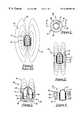
- FIG. 2is a top view of a first embodiment of a lamp assembly of the present invention
- FIG. 3is a cross-sectional view taken along the 3 — 3 line of FIG. 2 depicting the affect of the flux concentrator on magnetic flux lines produced by energization of the drive coil;
- FIG. 4is a cross-sectional view of a second embodiment of the invention that utilizes laminations of magnetically permeable material
- FIG. 5is a cross-sectional view of a third embodiment of the invention that operates to concentrate magnetic flux lines within the gas discharge lamp envelope.
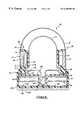
- FIG. 6is a cross-sectional view of an automotive lamp assembly constructed in accordance with the invention.
- FIG. 1depicts a prior art lamp assembly 10 which includes an electrodeless gas discharge lamp 12 having a low pressure fill of ionizable gas, such as neon, and an inductive drive coil 14 that receives operating power from an a.c. supply (not shown).
- a.c. supplynot shown
- energization of drive coil 14 by the a.c. supplyproduces a time-varying magnetic field which is depicted by the magnetic flux lines 16 .
- these flux linesemanate beyond the confines of the lamp assembly where they can interfere with other electronic and magnetic systems. When used for automotive lighting applications, this magnetic field could potentially interfere with such things as engine sensors or the vehicle electronic compass.
- the illustrated flux linesare diagrammatic only and, as will be understood by one skilled in the art, the magnetic field will actually extend much further away from lamp 12 than as indicated.
- Lamp assembly 20includes an electrodeless gas discharge lamp 12 and drive coil 14 as in FIG. 1, and further includes a flux concentrator 22 in the form of a tubular sleeve 24 .
- Sleeve 24is constructed of a magnetically permeable material (whether ferromagnetic or paramagnetic), such as iron powder metal or low carbon steel. As shown in FIG. 3, sleeve 24 provides a low reluctance path that serves to confine the magnetic flux lines 16 to an area closely adjacent the lamp assembly. This helps minimize the amount of magnetic field that emanates from the lamp assembly.
- sleeve 24is cylindrical in shape and is spaced from coil 14 by a gap 26 . This gap prevents possible shorting of the windings by sleeve 24 and helps minimize the effect of sleeve 24 on the inductance of coil 14 . As shown in FIG. 3, sleeve 24 is axially coextensive with drive coil 14 , although it will be appreciated by those skilled in the art that the length of sleeve 24 and its positioning relative to coil 14 can be selected to provide the desired degree of shaping and confinement of the magnetic field produced by coil 14 .
- sleeve 24includes an axial split 28 that extends the length of the sleeve. Also, to prevent eddy current losses, sleeve 24 can be made of ferrite or other non-conductive ferromagnetic material. Alternatively, laminations can be used, as in the second embodiment depicted in FIG. 4 .
- This figureshows a lamp assembly 30 that utilizes a flux concentrator 32 in the form of a sleeve 34 . This sleeve is similar to that of FIGS.
- annular laminations 36each comprise a magnetically permeable material that is coated on at least one side with a non-conductive material.
- a number of suitable non-ferromagnetic fasteners 38can be used to clamp the laminations 36 together.
- Sleeve 34can include an axial split (not shown) as in the first embodiment.
- the laminationscan be oriented other than as shown such that they can be stacked, for example, either radially (as in coaxial laminations) or angularly (as in sectored laminations).
- This embodimentcomprises a lamp assembly 40 which includes a lamp 12 ′, drive coil 14 , and a flux concentrator 42 in the form of a sleeve 44 , end piece 46 , and core piece 48 .
- These three portions of flux concentrator 42are integrally joined and together they provide a low reluctance path for the magnetic flux lines generated by coil 14 . If desired, these three portions can be formed from a single unitary piece of magnetically permeable material.
- Lamp 12 ′is similar to that of the other embodiments, except that it has a central recessed portion 50 that is coaxial with drive coil 14 . Lamp 12 ′ fits into flux concentrator 42 such that core piece 48 extends into recessed portion 50 . As indicated in FIG.
- this constructionconcentrates the magnetic field 16 into a solid angle located at a central portion of the lamp where the plasma discharge is primarily located. This is believe to provide better coupling of the magnetic field to the plasma discharge to thereby improve the efficiency of the lamp assembly.
- the shape and configuration of the flux concentratorcan be selected in accordance with the lamp geometry to control the shape, location, and density of the magnetic field passing through the lamp. In this way, the coupling of the magnetic field to the plasma discharge can be maximized to thereby increase the efficiency of the lamp assembly.
- core piece 48helps concentrate the flux lines 16 , as described above, it will be appreciated that the use o sleeve 44 and end piece 46 without core piece 48 still provides beneficial effects since these components can be used to shield an underlying a.c. power supply 52 .
- Electrical connections to drive coil 14can be by way of feedthrough holes in end piece 46 .
- an electrically conductive materialis used for flux concentrator 42 , it can be grounded to help reduce radiated r.f. emissions.
- FIG. 6there is depicted an automotive lamp assembly 60 that includes lamp 12 , drive coil 14 , and sleeve 24 , which is also designated generally as flux concentrator 22 .
- Coil 14 and sleeve 24are supported by a plastic housing 62 in which lamp 12 is mounted along with a suitable d.c. to a.c. inverter circuit 64 , the construction of which is known to those skilled in the art.
- the upper portion of housing 62comprises a bobbin 66 on which coil 14 is wound. This bobbin permits coil 14 to be wound prior to assembly of lamp 12 into the housing.
- Bobbin 66includes upper and lower annular flanges 68 , 70 which limit the axial extent of coil 14 .
- a pair of feedthrough terminals 72(only one shown) extend from the lower Range 70 of bobbin 66 to the inverter circuit 64 . These terminals are used to electrically connect drive coil 14 to inverter circuit 64 .
- Upper and lower flanges 68 , 70 of bobbin 66include respective opposing shoulders 74 , 76 which are used to retain sleeve 24 in a radially spaced position from coil 14 .
- sleeve 24is made from a ferrite material to limit eddy current losses.
- Sleeve 24can have a pair of opposed axial splits (not shown) extending the length of the sleeve such that it is in actuality formed from two separate partial cylinders, each having a semi-circular cross-section that extends slightly less than 180°.
- Shield 78is one part of a grounded r.f. shield 80 that also includes an upper hemispherical shield 82 , a lower cylindrical shield 84 , and a base shield 86 .
- Shield members 78 , 82 , 84 , and 86are all electrically connected together with either lower shield 84 or base shield 86 being connected to the circuit ground.
- Upper shield 82comprises a wire mesh that is selected to provide suitable r.f. shielding without creating a significant reduction in light output from lamp assembly 60 .
- r.f. shield 80provides a substantially complete enclosure of lamp 12 , coil 14 , and inverter circuit 64 . One location not entirely shielded by this arrangement is at the portions of housing 62 located between tabs 88 . To help prevent emission of r.f.
- lower shield 84includes an upstanding collar portion 92 which includes a number of angularly spaced slits. These slits are used to form spaced tabs 94 that, in addition to helping shield against emitted r.f. interference, can be bent inwardly after insertion of lamp 12 into housing 62 to thereby retain lamp 12 in place using a lip 96 of the lamp envelope which contacts the underside of bobbin 66 . Rather than forming tabs 94 by slits in collar 92 , the collar can simply be deformed inwardly at several locations around its circumference to thereby hold lamp 12 in place.
- Inverter circuit 64is located within the space defined by lower shield 84 and base shield 86 and can be implemented using one or more printed circuit boards 98 .
- the circuit boardscan be potted in place after assembly into housing 62 .
- a heat shield 100can be placed between the lamp envelope and circuit boards 98 .
- base shield 86includes a number of angularly spaced metal retaining clips 102 that help centrally locate lamp 12 in housing 62 via a nipple 104 that extends downwardly from the base of lamp 12 . These retaining clips also conduct heat from lamp 12 to base shield 86 .
- a heat sink 106can be provided underneath the bottom plate 108 of housing 62 to remove heat generated by inverter circuit 64 and lamp 12 .
- Heat sink 106can be retained to housing 62 using a number of protrusions 110 that extend upwardly through bottom plate 108 and base shield 86 . These protrusions each have an enlarged head 112 to hold heat sink 106 in place.
- bottom plate 108is formed of a thermally conductive material to aid in the conduction of heat from base shield 86 to heat sink 106 .
- D.C. operating poweris supplied to circuit boards 98 via terminals (not shown) which extend downwardly through base shield 86 , bottom plate 108 and heat sink 106 .
- Three terminalsare provided, one connected to circuit ground and the other two for receiving power to operate the lamp at each of two different brightness levels—a lower brightness level for normal taillight operation and a higher brightness level for signaling braking or for turn signal flashing.
- the ground terminalis electrically connected to r.f. shield 80 .
Landscapes
- Physics & Mathematics (AREA)
- Electromagnetism (AREA)
- Engineering & Computer Science (AREA)
- Plasma & Fusion (AREA)
- Circuit Arrangements For Discharge Lamps (AREA)
Abstract
Description
Claims (6)
Priority Applications (1)
| Application Number | Priority Date | Filing Date | Title |
|---|---|---|---|
| US09/165,976US6380680B1 (en) | 1998-10-02 | 1998-10-02 | Electrodeless gas discharge lamp assembly with flux concentrator |
Applications Claiming Priority (1)
| Application Number | Priority Date | Filing Date | Title |
|---|---|---|---|
| US09/165,976US6380680B1 (en) | 1998-10-02 | 1998-10-02 | Electrodeless gas discharge lamp assembly with flux concentrator |
Publications (1)
| Publication Number | Publication Date |
|---|---|
| US6380680B1true US6380680B1 (en) | 2002-04-30 |
Family
ID=22601284
Family Applications (1)
| Application Number | Title | Priority Date | Filing Date |
|---|---|---|---|
| US09/165,976Expired - Fee RelatedUS6380680B1 (en) | 1998-10-02 | 1998-10-02 | Electrodeless gas discharge lamp assembly with flux concentrator |
Country Status (1)
| Country | Link |
|---|---|
| US (1) | US6380680B1 (en) |
Cited By (20)
| Publication number | Priority date | Publication date | Assignee | Title |
|---|---|---|---|---|
| US20030132706A1 (en)* | 2001-12-28 | 2003-07-17 | Kenji Itaya | Electrodeless discharge lamp |
| US6653783B2 (en)* | 2000-09-26 | 2003-11-25 | Matsushita Electric Industrial Co., Ltd. | Self-ballasted electrodeless discharge lamp with startability improving means |
| US20070210717A1 (en)* | 2004-07-09 | 2007-09-13 | Energetiq Technology Inc. | Inductively-driven plasma light source |
| US20080042591A1 (en)* | 2004-07-09 | 2008-02-21 | Energetiq Technology Inc. | Inductively-Driven Plasma Light Source |
| US20080050292A1 (en)* | 2006-08-28 | 2008-02-28 | Valery Godyak | Plasma reactor with inductie excitation of plasma and efficient removal of heat from the excitation coil |
| US20080050537A1 (en)* | 2006-08-22 | 2008-02-28 | Valery Godyak | Inductive plasma source with high coupling efficiency |
| JP2008524861A (en)* | 2004-12-22 | 2008-07-10 | ジン リ | Interpolated magnetic energy generator and magnetic energy lamp equipped with the interpolated magnetic energy generator |
| EP2187711A3 (en)* | 2004-07-09 | 2010-07-21 | Energetiq Technology Inc. | Inductively-driven plasma light source |
| US7772773B1 (en) | 2003-11-13 | 2010-08-10 | Imaging Systems Technology | Electrode configurations for plasma-dome PDP |
| US8035303B1 (en) | 2006-02-16 | 2011-10-11 | Imaging Systems Technology | Electrode configurations for gas discharge device |
| US8113898B1 (en) | 2004-06-21 | 2012-02-14 | Imaging Systems Technology, Inc. | Gas discharge device with electrical conductive bonding material |
| US8198811B1 (en) | 2002-05-21 | 2012-06-12 | Imaging Systems Technology | Plasma-Disc PDP |
| US8278824B1 (en) | 2006-02-16 | 2012-10-02 | Imaging Systems Technology, Inc. | Gas discharge electrode configurations |
| US8299696B1 (en) | 2005-02-22 | 2012-10-30 | Imaging Systems Technology | Plasma-shell gas discharge device |
| US20120285202A1 (en)* | 2007-12-10 | 2012-11-15 | Fleming James W | Method Of Fabricating Optical Fiber Using An Isothermal, Low Pressure Plasma Deposition Technique |
| US8339041B1 (en) | 2004-04-26 | 2012-12-25 | Imaging Systems Technology, Inc. | Plasma-shell gas discharge device with combined organic and inorganic luminescent substances |
| US8368303B1 (en) | 2004-06-21 | 2013-02-05 | Imaging Systems Technology, Inc. | Gas discharge device with electrical conductive bonding material |
| US8410695B1 (en) | 2006-02-16 | 2013-04-02 | Imaging Systems Technology | Gas discharge device incorporating gas-filled plasma-shell and method of manufacturing thereof |
| US8618733B1 (en) | 2006-01-26 | 2013-12-31 | Imaging Systems Technology, Inc. | Electrode configurations for plasma-shell gas discharge device |
| US9013102B1 (en) | 2009-05-23 | 2015-04-21 | Imaging Systems Technology, Inc. | Radiation detector with tiled substrates |
Citations (20)
| Publication number | Priority date | Publication date | Assignee | Title |
|---|---|---|---|---|
| US2287607A (en)* | 1940-03-05 | 1942-06-23 | Farnsworth Television & Radio | Rectifier |
| US2947901A (en)* | 1956-03-23 | 1960-08-02 | Burroughs Corp | Magnetron tube shield |
| US2974243A (en)* | 1959-11-12 | 1961-03-07 | Space Technology Lab Inc | Light source |
| US3950670A (en)* | 1974-10-29 | 1976-04-13 | Westinghouse Electric Corporation | Electrodeless discharge adaptor system |
| US4000432A (en) | 1975-07-25 | 1976-12-28 | Varian Associates | Magnetic shield for image intensifier tube |
| US4152745A (en) | 1977-04-11 | 1979-05-01 | Eul Edward A | Magnetic shield device |
| US4561489A (en) | 1982-03-25 | 1985-12-31 | Olin Corporation | Flux concentrator |
| US4797595A (en) | 1986-06-30 | 1989-01-10 | U.S. Philips Corp. | Electrodeless low-pressure discharge lamp having a straight exhaust tube fixed on a conical stem |
| US4902937A (en) | 1988-07-28 | 1990-02-20 | General Electric Company | Capacitive starting electrodes for hid lamps |
| US5027041A (en) | 1990-01-16 | 1991-06-25 | Gte Products Corporation | Integrated radio-frequency light source for large scale display |
| US5276419A (en) | 1992-02-18 | 1994-01-04 | The United States Of America As Represented By The Secretary Of The Air Force | Air-code magnetic flux guide |
| US5529747A (en) | 1993-11-10 | 1996-06-25 | Learflux, Inc. | Formable composite magnetic flux concentrator and method of making the concentrator |
| US5539283A (en) | 1995-06-14 | 1996-07-23 | Osram Sylvania Inc. | Discharge light source with reduced magnetic interference |
| US5621266A (en) | 1995-10-03 | 1997-04-15 | Matsushita Electric Works Research And Development Laboraty Inc. | Electrodeless fluorescent lamp |
| US5630958A (en) | 1995-01-27 | 1997-05-20 | Stewart, Jr.; John B. | Side entry coil induction heater with flux concentrator |
| US5698951A (en)* | 1996-05-06 | 1997-12-16 | Matsushita Electric Works Research & Development Labratory | Electrodeless discharge lamp and device for increasing the lamp's luminous development |
| US5723947A (en)* | 1996-12-20 | 1998-03-03 | Matsushita Electric Works Research & Development Laboratories Inc. | Electrodeless inductively-coupled fluorescent lamp with improved cavity and tubulation |
| US5723941A (en) | 1995-05-24 | 1998-03-03 | U.S. Philips Corporation | Lighting unit, electrodeless low-pressure discharge lamp, and discharge vessel for use in the lighting unit |
| US6087774A (en)* | 1996-10-31 | 2000-07-11 | Kabushiki Kaisha Toshiba | Non-electrode discharge lamp apparatus and liquid treatment apparatus using such lamp apparatus |
| US6118226A (en)* | 1998-07-31 | 2000-09-12 | Federal-Mogul World Wide, Inc. | Electrodeless neon light module for vehicle lighting systems |
- 1998
- 1998-10-02USUS09/165,976patent/US6380680B1/ennot_activeExpired - Fee Related
Patent Citations (20)
| Publication number | Priority date | Publication date | Assignee | Title |
|---|---|---|---|---|
| US2287607A (en)* | 1940-03-05 | 1942-06-23 | Farnsworth Television & Radio | Rectifier |
| US2947901A (en)* | 1956-03-23 | 1960-08-02 | Burroughs Corp | Magnetron tube shield |
| US2974243A (en)* | 1959-11-12 | 1961-03-07 | Space Technology Lab Inc | Light source |
| US3950670A (en)* | 1974-10-29 | 1976-04-13 | Westinghouse Electric Corporation | Electrodeless discharge adaptor system |
| US4000432A (en) | 1975-07-25 | 1976-12-28 | Varian Associates | Magnetic shield for image intensifier tube |
| US4152745A (en) | 1977-04-11 | 1979-05-01 | Eul Edward A | Magnetic shield device |
| US4561489A (en) | 1982-03-25 | 1985-12-31 | Olin Corporation | Flux concentrator |
| US4797595A (en) | 1986-06-30 | 1989-01-10 | U.S. Philips Corp. | Electrodeless low-pressure discharge lamp having a straight exhaust tube fixed on a conical stem |
| US4902937A (en) | 1988-07-28 | 1990-02-20 | General Electric Company | Capacitive starting electrodes for hid lamps |
| US5027041A (en) | 1990-01-16 | 1991-06-25 | Gte Products Corporation | Integrated radio-frequency light source for large scale display |
| US5276419A (en) | 1992-02-18 | 1994-01-04 | The United States Of America As Represented By The Secretary Of The Air Force | Air-code magnetic flux guide |
| US5529747A (en) | 1993-11-10 | 1996-06-25 | Learflux, Inc. | Formable composite magnetic flux concentrator and method of making the concentrator |
| US5630958A (en) | 1995-01-27 | 1997-05-20 | Stewart, Jr.; John B. | Side entry coil induction heater with flux concentrator |
| US5723941A (en) | 1995-05-24 | 1998-03-03 | U.S. Philips Corporation | Lighting unit, electrodeless low-pressure discharge lamp, and discharge vessel for use in the lighting unit |
| US5539283A (en) | 1995-06-14 | 1996-07-23 | Osram Sylvania Inc. | Discharge light source with reduced magnetic interference |
| US5621266A (en) | 1995-10-03 | 1997-04-15 | Matsushita Electric Works Research And Development Laboraty Inc. | Electrodeless fluorescent lamp |
| US5698951A (en)* | 1996-05-06 | 1997-12-16 | Matsushita Electric Works Research & Development Labratory | Electrodeless discharge lamp and device for increasing the lamp's luminous development |
| US6087774A (en)* | 1996-10-31 | 2000-07-11 | Kabushiki Kaisha Toshiba | Non-electrode discharge lamp apparatus and liquid treatment apparatus using such lamp apparatus |
| US5723947A (en)* | 1996-12-20 | 1998-03-03 | Matsushita Electric Works Research & Development Laboratories Inc. | Electrodeless inductively-coupled fluorescent lamp with improved cavity and tubulation |
| US6118226A (en)* | 1998-07-31 | 2000-09-12 | Federal-Mogul World Wide, Inc. | Electrodeless neon light module for vehicle lighting systems |
Cited By (29)
| Publication number | Priority date | Publication date | Assignee | Title |
|---|---|---|---|---|
| US6653783B2 (en)* | 2000-09-26 | 2003-11-25 | Matsushita Electric Industrial Co., Ltd. | Self-ballasted electrodeless discharge lamp with startability improving means |
| US6762550B2 (en)* | 2001-12-28 | 2004-07-13 | Matsushita Electric Industrial Co., Ltd. | Electrodeless discharge lamp |
| US20030132706A1 (en)* | 2001-12-28 | 2003-07-17 | Kenji Itaya | Electrodeless discharge lamp |
| US8198811B1 (en) | 2002-05-21 | 2012-06-12 | Imaging Systems Technology | Plasma-Disc PDP |
| US7772773B1 (en) | 2003-11-13 | 2010-08-10 | Imaging Systems Technology | Electrode configurations for plasma-dome PDP |
| US8339041B1 (en) | 2004-04-26 | 2012-12-25 | Imaging Systems Technology, Inc. | Plasma-shell gas discharge device with combined organic and inorganic luminescent substances |
| US8113898B1 (en) | 2004-06-21 | 2012-02-14 | Imaging Systems Technology, Inc. | Gas discharge device with electrical conductive bonding material |
| US8368303B1 (en) | 2004-06-21 | 2013-02-05 | Imaging Systems Technology, Inc. | Gas discharge device with electrical conductive bonding material |
| US20070210717A1 (en)* | 2004-07-09 | 2007-09-13 | Energetiq Technology Inc. | Inductively-driven plasma light source |
| EP2187711A3 (en)* | 2004-07-09 | 2010-07-21 | Energetiq Technology Inc. | Inductively-driven plasma light source |
| US20080042591A1 (en)* | 2004-07-09 | 2008-02-21 | Energetiq Technology Inc. | Inductively-Driven Plasma Light Source |
| US7948185B2 (en) | 2004-07-09 | 2011-05-24 | Energetiq Technology Inc. | Inductively-driven plasma light source |
| US8143790B2 (en) | 2004-07-09 | 2012-03-27 | Energetiq Technology, Inc. | Method for inductively-driven plasma light source |
| JP2008524861A (en)* | 2004-12-22 | 2008-07-10 | ジン リ | Interpolated magnetic energy generator and magnetic energy lamp equipped with the interpolated magnetic energy generator |
| US8299696B1 (en) | 2005-02-22 | 2012-10-30 | Imaging Systems Technology | Plasma-shell gas discharge device |
| US8618733B1 (en) | 2006-01-26 | 2013-12-31 | Imaging Systems Technology, Inc. | Electrode configurations for plasma-shell gas discharge device |
| US8410695B1 (en) | 2006-02-16 | 2013-04-02 | Imaging Systems Technology | Gas discharge device incorporating gas-filled plasma-shell and method of manufacturing thereof |
| US8035303B1 (en) | 2006-02-16 | 2011-10-11 | Imaging Systems Technology | Electrode configurations for gas discharge device |
| US8278824B1 (en) | 2006-02-16 | 2012-10-02 | Imaging Systems Technology, Inc. | Gas discharge electrode configurations |
| US8444870B2 (en)* | 2006-08-22 | 2013-05-21 | Mattson Technology, Inc. | Inductive plasma source with high coupling efficiency |
| US20080050537A1 (en)* | 2006-08-22 | 2008-02-28 | Valery Godyak | Inductive plasma source with high coupling efficiency |
| US20100136262A1 (en)* | 2006-08-22 | 2010-06-03 | Valery Godyak | Inductive plasma source with high coupling efficiency |
| US8920600B2 (en) | 2006-08-22 | 2014-12-30 | Mattson Technology, Inc. | Inductive plasma source with high coupling efficiency |
| US10037867B2 (en) | 2006-08-22 | 2018-07-31 | Mattson Technology, Inc. | Inductive plasma source with high coupling efficiency |
| US20080050292A1 (en)* | 2006-08-28 | 2008-02-28 | Valery Godyak | Plasma reactor with inductie excitation of plasma and efficient removal of heat from the excitation coil |
| US8992725B2 (en) | 2006-08-28 | 2015-03-31 | Mattson Technology, Inc. | Plasma reactor with inductie excitation of plasma and efficient removal of heat from the excitation coil |
| US10090134B2 (en) | 2006-08-28 | 2018-10-02 | Mattson Technology, Inc. | Plasma reactor with inductive excitation of plasma and efficient removal of heat from the excitation coil |
| US20120285202A1 (en)* | 2007-12-10 | 2012-11-15 | Fleming James W | Method Of Fabricating Optical Fiber Using An Isothermal, Low Pressure Plasma Deposition Technique |
| US9013102B1 (en) | 2009-05-23 | 2015-04-21 | Imaging Systems Technology, Inc. | Radiation detector with tiled substrates |
Similar Documents
| Publication | Publication Date | Title |
|---|---|---|
| US6380680B1 (en) | Electrodeless gas discharge lamp assembly with flux concentrator | |
| US4613841A (en) | Integrated transformer and inductor | |
| CN101692418B (en) | Electrodeless fluorescent lamp | |
| EP0585108B1 (en) | Fluorescent lamp | |
| US5349271A (en) | Electrodeless discharge lamp with spiral induction coil | |
| EP0766500B1 (en) | Ballast with balancer transformer for fluorescent lamps | |
| CA2000467C (en) | High-frequency heating apparatus using frequency-converter-type power supply | |
| EP0890977A1 (en) | Electrodeless lamp having compensation loop for suppression of magnetic interference | |
| WO2000054558A1 (en) | Circuit arrangement | |
| KR930000415B1 (en) | Magnetic leakage transformer | |
| US5959407A (en) | Vehicle lighting drive apparatus | |
| US7259356B2 (en) | Temperature self-regulating soldering iron with removable tip | |
| US6297583B1 (en) | Gas discharge lamp assembly with improved r.f. shielding | |
| CN107276240B (en) | Power transmission device | |
| US4409521A (en) | Fluorescent lamp with reduced electromagnetic interference | |
| US6366023B1 (en) | Starter modules for motor vehicle headlight discharge lamps | |
| US20010019297A1 (en) | Rod ignition transformer for internal-combustion engines | |
| JP3671686B2 (en) | Electrodeless discharge lamp device | |
| JP2007265816A (en) | Electrodeless discharge lamp lighting device and luminaire | |
| JP2004342339A (en) | Induction heating cooker | |
| CN101116378A (en) | Lampholders for high-pressure discharge lamps and high-pressure discharge lamps | |
| KR940003598Y1 (en) | Low-pass filter structure of input part of microwave oven magnetron | |
| GB2138629A (en) | High-frequency gas-discharge lamp system | |
| JPH09231949A (en) | Electrodeless low pressure discharge lamp | |
| KR100460329B1 (en) | electrodeless discharge lamp |
Legal Events
| Date | Code | Title | Description |
|---|---|---|---|
| AS | Assignment | Owner name:FEDERAL-MOGUL WORLD WIDE, INC., MICHIGAN Free format text:ASSIGNMENT OF ASSIGNORS INTEREST;ASSIGNOR:TROXLER, JOHN E.;REEL/FRAME:009543/0332 Effective date:19981002 | |
| AS | Assignment | Owner name:WILMINGTON TRUST COMPANY, AS TRUSTEE, DELAWARE Free format text:SECURITY INTEREST;ASSIGNOR:FEDERAL-MOGUL WORLD WIDE, INC. (MI CORPORATION);REEL/FRAME:011466/0001 Effective date:20001229 | |
| CC | Certificate of correction | ||
| FPAY | Fee payment | Year of fee payment:4 | |
| AS | Assignment | Owner name:FEDERAL-MOGUL WORLDWIDE, INC., MICHIGAN Free format text:RELEASE OF SECURITY INTEREST RECORDED AT REEL/FRAME 011571/0001 AND 011466/0001;ASSIGNOR:WILMINGTON TRUST COMPANY, AS TRUSTEE;REEL/FRAME:020299/0377 Effective date:20071217 | |
| AS | Assignment | Owner name:CITIBANK, N.A. AS COLLATERAL TRUSTEE, NEW YORK Free format text:SECURITY AGREEMENT;ASSIGNOR:FEDERAL-MOGUL WORLD WIDE, INC.;REEL/FRAME:020362/0139 Effective date:20071227 Owner name:CITIBANK, N.A. AS COLLATERAL TRUSTEE,NEW YORK Free format text:SECURITY AGREEMENT;ASSIGNOR:FEDERAL-MOGUL WORLD WIDE, INC.;REEL/FRAME:020362/0139 Effective date:20071227 | |
| REMI | Maintenance fee reminder mailed | ||
| LAPS | Lapse for failure to pay maintenance fees | ||
| STCH | Information on status: patent discontinuation | Free format text:PATENT EXPIRED DUE TO NONPAYMENT OF MAINTENANCE FEES UNDER 37 CFR 1.362 | |
| FP | Lapsed due to failure to pay maintenance fee | Effective date:20100430 | |
| AS | Assignment | Owner name:FEDERAL-MOGUL WORLD WIDE LLC (FORMERLY FEDERAL-MOGUL WORLD WIDE, INC.), MICHIGAN Free format text:RELEASE BY SECURED PARTY;ASSIGNOR:CITIBANK, N.A.;REEL/FRAME:062389/0149 Effective date:20230112 |