US6379378B1 - Lumen design for catheter - Google Patents
Lumen design for catheterDownload PDFInfo
- Publication number
- US6379378B1 US6379378B1US09/519,022US51902200AUS6379378B1US 6379378 B1US6379378 B1US 6379378B1US 51902200 AUS51902200 AUS 51902200AUS 6379378 B1US6379378 B1US 6379378B1
- Authority
- US
- United States
- Prior art keywords
- lumen
- heat transfer
- working fluid
- transfer element
- interior
- Prior art date
- Legal status (The legal status is an assumption and is not a legal conclusion. Google has not performed a legal analysis and makes no representation as to the accuracy of the status listed.)
- Expired - Fee Related
Links
- 238000013461designMethods0.000titledescription10
- 238000012546transferMethods0.000claimsabstractdescription567
- 239000012530fluidSubstances0.000claimsabstractdescription348
- 238000001816coolingMethods0.000claimsabstractdescription62
- 210000004204blood vesselAnatomy0.000claimsabstractdescription52
- 238000010438heat treatmentMethods0.000claimsabstractdescription37
- 230000002792vascularEffects0.000claimsabstractdescription11
- 238000003780insertionMethods0.000claimsabstractdescription8
- 230000037431insertionEffects0.000claimsabstractdescription8
- 238000002156mixingMethods0.000claimsdescription75
- 239000008280bloodSubstances0.000claimsdescription63
- 210000004369bloodAnatomy0.000claimsdescription63
- 238000000034methodMethods0.000claimsdescription31
- 230000000694effectsEffects0.000claimsdescription30
- 230000001939inductive effectEffects0.000claimsdescription17
- 230000007246mechanismEffects0.000claimsdescription13
- 230000002708enhancing effectEffects0.000claimsdescription11
- 239000000203mixtureSubstances0.000claimsdescription4
- 238000004519manufacturing processMethods0.000abstractdescription4
- 210000001367arteryAnatomy0.000description34
- FAPWRFPIFSIZLT-UHFFFAOYSA-MSodium chlorideChemical compound[Na+].[Cl-]FAPWRFPIFSIZLT-UHFFFAOYSA-M0.000description23
- 210000004556brainAnatomy0.000description23
- 210000000056organAnatomy0.000description22
- 239000011780sodium chlorideSubstances0.000description20
- 230000002631hypothermal effectEffects0.000description19
- 238000012377drug deliveryMethods0.000description18
- 230000017531blood circulationEffects0.000description15
- 239000002826coolantSubstances0.000description14
- 230000001965increasing effectEffects0.000description14
- 239000000463materialSubstances0.000description14
- 210000001715carotid arteryAnatomy0.000description11
- 210000001168carotid artery commonAnatomy0.000description11
- 229910052751metalInorganic materials0.000description11
- 239000002184metalSubstances0.000description11
- 230000003902lesionEffects0.000description10
- 230000000747cardiac effectEffects0.000description8
- 239000000243solutionSubstances0.000description8
- XLYOFNOQVPJJNP-UHFFFAOYSA-NwaterSubstancesOXLYOFNOQVPJJNP-UHFFFAOYSA-N0.000description8
- 210000004004carotid artery internalAnatomy0.000description7
- 230000033001locomotionEffects0.000description7
- 108090000790EnzymesProteins0.000description6
- 102000004190EnzymesHuman genes0.000description6
- 229940088598enzymeDrugs0.000description6
- 238000010276constructionMethods0.000description5
- 229940079593drugDrugs0.000description5
- 239000003814drugSubstances0.000description5
- 210000001105femoral arteryAnatomy0.000description5
- 210000002216heartAnatomy0.000description5
- IJGRMHOSHXDMSA-UHFFFAOYSA-NAtomic nitrogenChemical compoundN#NIJGRMHOSHXDMSA-UHFFFAOYSA-N0.000description4
- 229920002614Polyether block amidePolymers0.000description4
- 238000002583angiographyMethods0.000description4
- 239000007788liquidSubstances0.000description4
- 230000010412perfusionEffects0.000description4
- 238000011282treatmentMethods0.000description4
- 239000013598vectorSubstances0.000description4
- 210000003462veinAnatomy0.000description4
- 208000032843HemorrhageDiseases0.000description3
- 229920006362Teflon®Polymers0.000description3
- 238000013459approachMethods0.000description3
- 208000034158bleedingDiseases0.000description3
- 230000000740bleeding effectEffects0.000description3
- 230000036760body temperatureEffects0.000description3
- 230000002490cerebral effectEffects0.000description3
- 230000035602clottingEffects0.000description3
- 239000004020conductorSubstances0.000description3
- 230000006378damageEffects0.000description3
- 230000007423decreaseEffects0.000description3
- 230000003247decreasing effectEffects0.000description3
- 230000001419dependent effectEffects0.000description3
- -1e.g.Polymers0.000description3
- 239000003527fibrinolytic agentSubstances0.000description3
- 230000003480fibrinolytic effectEffects0.000description3
- 238000002594fluoroscopyMethods0.000description3
- 238000009413insulationMethods0.000description3
- 229920000642polymerPolymers0.000description3
- 230000008569processEffects0.000description3
- 238000007789sealingMethods0.000description3
- 230000002966stenotic effectEffects0.000description3
- 230000002459sustained effectEffects0.000description3
- 230000001225therapeutic effectEffects0.000description3
- 238000002560therapeutic procedureMethods0.000description3
- 230000002537thrombolytic effectEffects0.000description3
- 230000000472traumatic effectEffects0.000description3
- 238000002604ultrasonographyMethods0.000description3
- 238000005406washingMethods0.000description3
- PXHVJJICTQNCMI-UHFFFAOYSA-NNickelChemical compound[Ni]PXHVJJICTQNCMI-UHFFFAOYSA-N0.000description2
- 241000282520PapioSpecies0.000description2
- 208000031481Pathologic ConstrictionDiseases0.000description2
- 230000009471actionEffects0.000description2
- 210000003484anatomyAnatomy0.000description2
- 239000003146anticoagulant agentSubstances0.000description2
- 230000009286beneficial effectEffects0.000description2
- 238000009835boilingMethods0.000description2
- 238000000576coating methodMethods0.000description2
- 238000004891communicationMethods0.000description2
- 229940039231contrast mediaDrugs0.000description2
- 239000002872contrast mediaSubstances0.000description2
- 239000012809cooling fluidSubstances0.000description2
- 238000003745diagnosisMethods0.000description2
- 238000010790dilutionMethods0.000description2
- 239000012895dilutionSubstances0.000description2
- 238000002651drug therapyMethods0.000description2
- 239000007789gasSubstances0.000description2
- 208000014674injuryDiseases0.000description2
- 208000028867ischemiaDiseases0.000description2
- 210000003734kidneyAnatomy0.000description2
- 229920000126latexPolymers0.000description2
- 150000002739metalsChemical class0.000description2
- 229910052757nitrogenInorganic materials0.000description2
- 239000002245particleSubstances0.000description2
- BASFCYQUMIYNBI-UHFFFAOYSA-NplatinumChemical compound[Pt]BASFCYQUMIYNBI-UHFFFAOYSA-N0.000description2
- 239000002861polymer materialSubstances0.000description2
- 229910001220stainless steelInorganic materials0.000description2
- 239000010935stainless steelSubstances0.000description2
- 230000036262stenosisEffects0.000description2
- 208000037804stenosisDiseases0.000description2
- 230000007704transitionEffects0.000description2
- 238000011144upstream manufacturingMethods0.000description2
- 206010001526Air embolismDiseases0.000description1
- 108010039209Blood Coagulation FactorsProteins0.000description1
- 102000015081Blood Coagulation FactorsHuman genes0.000description1
- RYGMFSIKBFXOCR-UHFFFAOYSA-NCopperChemical compound[Cu]RYGMFSIKBFXOCR-UHFFFAOYSA-N0.000description1
- LFQSCWFLJHTTHZ-UHFFFAOYSA-NEthanolChemical compoundCCOLFQSCWFLJHTTHZ-UHFFFAOYSA-N0.000description1
- HTTJABKRGRZYRN-UHFFFAOYSA-NHeparinChemical compoundOC1C(NC(=O)C)C(O)OC(COS(O)(=O)=O)C1OC1C(OS(O)(=O)=O)C(O)C(OC2C(C(OS(O)(=O)=O)C(OC3C(C(O)C(O)C(O3)C(O)=O)OS(O)(=O)=O)C(CO)O2)NS(O)(=O)=O)C(C(O)=O)O1HTTJABKRGRZYRN-UHFFFAOYSA-N0.000description1
- 241000282412HomoSpecies0.000description1
- NNJVILVZKWQKPM-UHFFFAOYSA-NLidocaineChemical compoundCCN(CC)CC(=O)NC1=C(C)C=CC=C1CNNJVILVZKWQKPM-UHFFFAOYSA-N0.000description1
- 239000004642PolyimideSubstances0.000description1
- BQCADISMDOOEFD-UHFFFAOYSA-NSilverChemical compound[Ag]BQCADISMDOOEFD-UHFFFAOYSA-N0.000description1
- 108010023197StreptokinaseProteins0.000description1
- 208000007536ThrombosisDiseases0.000description1
- RTAQQCXQSZGOHL-UHFFFAOYSA-NTitaniumChemical compound[Ti]RTAQQCXQSZGOHL-UHFFFAOYSA-N0.000description1
- 208000030886Traumatic Brain injuryDiseases0.000description1
- 108090000435Urokinase-type plasminogen activatorProteins0.000description1
- 102000003990Urokinase-type plasminogen activatorHuman genes0.000description1
- 208000027418Wounds and injuryDiseases0.000description1
- 238000002679ablationMethods0.000description1
- 238000009825accumulationMethods0.000description1
- 229910052782aluminiumInorganic materials0.000description1
- XAGFODPZIPBFFR-UHFFFAOYSA-NaluminiumChemical compound[Al]XAGFODPZIPBFFR-UHFFFAOYSA-N0.000description1
- 230000010100anticoagulationEffects0.000description1
- 210000000709aortaAnatomy0.000description1
- 239000007864aqueous solutionSubstances0.000description1
- 230000004872arterial blood pressureEffects0.000description1
- 230000000712assemblyEffects0.000description1
- 238000000429assemblyMethods0.000description1
- 238000010009beatingMethods0.000description1
- 238000005452bendingMethods0.000description1
- 230000015572biosynthetic processEffects0.000description1
- 239000003114blood coagulation factorSubstances0.000description1
- 208000029028brain injuryDiseases0.000description1
- 210000004720cerebrumAnatomy0.000description1
- 230000008859changeEffects0.000description1
- 230000004087circulationEffects0.000description1
- 239000011248coating agentSubstances0.000description1
- 230000001010compromised effectEffects0.000description1
- 229910052802copperInorganic materials0.000description1
- 239000010949copperSubstances0.000description1
- 230000036757core body temperatureEffects0.000description1
- 230000003205diastolic effectEffects0.000description1
- 238000009792diffusion processMethods0.000description1
- 201000010099diseaseDiseases0.000description1
- 208000037265diseases, disorders, signs and symptomsDiseases0.000description1
- 238000009826distributionMethods0.000description1
- 230000002526effect on cardiovascular systemEffects0.000description1
- 229920001971elastomerPolymers0.000description1
- 210000003191femoral veinAnatomy0.000description1
- 229920002457flexible plasticPolymers0.000description1
- 230000004907fluxEffects0.000description1
- 238000007710freezingMethods0.000description1
- 230000008014freezingEffects0.000description1
- PCHJSUWPFVWCPO-UHFFFAOYSA-NgoldChemical compound[Au]PCHJSUWPFVWCPO-UHFFFAOYSA-N0.000description1
- 229910052737goldInorganic materials0.000description1
- 239000010931goldSubstances0.000description1
- 150000008282halocarbonsChemical class0.000description1
- 229960002897heparinDrugs0.000description1
- 229920000669heparinPolymers0.000description1
- 238000003384imaging methodMethods0.000description1
- 208000015181infectious diseaseDiseases0.000description1
- 150000002500ionsChemical class0.000description1
- 208000037906ischaemic injuryDiseases0.000description1
- 230000000302ischemic effectEffects0.000description1
- 238000003475laminationMethods0.000description1
- 238000000608laser ablationMethods0.000description1
- 229960004194lidocaineDrugs0.000description1
- 230000013011matingEffects0.000description1
- 238000012544monitoring processMethods0.000description1
- 230000000926neurological effectEffects0.000description1
- 230000000324neuroprotective effectEffects0.000description1
- 229910052759nickelInorganic materials0.000description1
- 231100000252nontoxicToxicity0.000description1
- 230000003000nontoxic effectEffects0.000description1
- 230000008816organ damageEffects0.000description1
- 230000003534oscillatory effectEffects0.000description1
- 230000000737periodic effectEffects0.000description1
- 230000002093peripheral effectEffects0.000description1
- 239000004033plasticSubstances0.000description1
- 229920003023plasticPolymers0.000description1
- 238000007747platingMethods0.000description1
- 229910052697platinumInorganic materials0.000description1
- 229920001721polyimidePolymers0.000description1
- 229920001343polytetrafluoroethylenePolymers0.000description1
- 239000004810polytetrafluoroethyleneSubstances0.000description1
- 229920002635polyurethanePolymers0.000description1
- 239000004814polyurethaneSubstances0.000description1
- 230000002035prolonged effectEffects0.000description1
- 230000010349pulsationEffects0.000description1
- 230000009467reductionEffects0.000description1
- 239000003507refrigerantSubstances0.000description1
- 230000001105regulatory effectEffects0.000description1
- 230000033764rhythmic processEffects0.000description1
- 210000005245right atriumAnatomy0.000description1
- 108010073863saruplaseProteins0.000description1
- 229910052709silverInorganic materials0.000description1
- 239000004332silverSubstances0.000description1
- 210000003625skullAnatomy0.000description1
- 239000002002slurrySubstances0.000description1
- 239000011343solid materialSubstances0.000description1
- 229960005202streptokinaseDrugs0.000description1
- 238000001356surgical procedureMethods0.000description1
- 230000009885systemic effectEffects0.000description1
- 238000012360testing methodMethods0.000description1
- 229960000103thrombolytic agentDrugs0.000description1
- 210000001519tissueAnatomy0.000description1
- 229910052719titaniumInorganic materials0.000description1
- 239000010936titaniumSubstances0.000description1
- 238000013519translationMethods0.000description1
- 230000014616translationEffects0.000description1
- 230000008733traumaEffects0.000description1
- 230000009529traumatic brain injuryEffects0.000description1
- 229960005356urokinaseDrugs0.000description1
- 210000001631vena cava inferiorAnatomy0.000description1
- 210000002620vena cava superiorAnatomy0.000description1
- 238000010792warmingMethods0.000description1
Images


Classifications
- A—HUMAN NECESSITIES
- A61—MEDICAL OR VETERINARY SCIENCE; HYGIENE
- A61F—FILTERS IMPLANTABLE INTO BLOOD VESSELS; PROSTHESES; DEVICES PROVIDING PATENCY TO, OR PREVENTING COLLAPSING OF, TUBULAR STRUCTURES OF THE BODY, e.g. STENTS; ORTHOPAEDIC, NURSING OR CONTRACEPTIVE DEVICES; FOMENTATION; TREATMENT OR PROTECTION OF EYES OR EARS; BANDAGES, DRESSINGS OR ABSORBENT PADS; FIRST-AID KITS
- A61F7/00—Heating or cooling appliances for medical or therapeutic treatment of the human body
- A61F7/12—Devices for heating or cooling internal body cavities
- A61F2007/126—Devices for heating or cooling internal body cavities for invasive application, e.g. for introducing into blood vessels
Definitions
- the present inventionrelates generally to lumen designs for catheters. More particularly, the invention relates to lumen designs for catheters that modify and control the temperature of a selected body organ.
- Hypothermiacan be clinically defined as a core body temperature of 35° C. or less. Hypothermia is sometimes characterized further according to its severity. A body core temperature in the range of 33° C. to 35° C. is described as mild hypothermia. A body temperature of 28° C. to 32° C. is described as moderate hypothermia. A body core temperature in the range of 24° C. to 28° C. is described as severe hypothermia.
- hypothermiais uniquely effective in reducing brain injury caused by a variety of neurological insults and may eventually play an important role in emergency brain resuscitation.
- Experimental evidencehas demonstrated that cerebral cooling improves outcome after global ischemia, focal ischemia, or traumatic brain injury. For this reason, hypothermia may be induced in order to reduce the effect of certain bodily injuries to the brain as well as other organs.
- Cerebral hypothermiahas traditionally been accomplished through whole body cooling to create a condition of total body hypothermia in the range of 20° C. to 30° C.
- U.S. Pat. No. 3,425,419 to Datodescribes a method and apparatus of lowering and raising the temperature of the human body. Dato induces moderate hypothermia in a patient using a metallic catheter.
- the metallic catheterhas an inner passageway through which a fluid, such as water, can be circulated.
- the catheteris inserted through the femoral vein and then through the inferior vena cava as far as the right atrium and the superior vena cava.
- the Dato catheterhas an elongated cylindrical shape and is constructed from stainless steel.
- Datosuggests the use of a catheter approximately 70 cm in length and approximately 6 mm in diameter.
- Catheters adapted for delivering heat transfer fluids at temperatures above or below normal body temperatures to selected internal body siteshave been devised in the past (See, for example, U.S. Pat. No. 5,624,392 to Saab). These catheters often have a concentric, coaxial configuration of multiple lumens. The configurations often have a first central lumen adapted to receive a guide surrounded by a concentric second supply lumen adapted to supply a working fluid to a distal portion of the catheter and an outer concentric third return lumen, which surrounds the second lumen, adapted to return a working fluid to a fluid source.
- a problem with this configurationis that the working fluid in the supply lumen makes surface area contact with both an outer wall, which partially defines the outer limits of the second lumen, and an inner wall, which defines the first lumen, leading to increased heat transfer between the walls and the working fluid.
- the second supply lumen in the catheteris designed to deliver a cooling fluid to the distal portion of the catheter, the increased surface area contact caused by this configuration unnecessarily warms the cooling fluid prior to delivery to the distal portion of the catheter.
- Another problem with these cathetersis that the supply lumen(s) and return lumen(s) are not sized relative to each other to maximize the flow rate through the catheter. Hence, they do not optimize heating and/or cooling catheter performance.
- the present inventioninvolves a device for heating or cooling a surrounding fluid in a blood vessel that addresses and solves the problems discussed above with multiple lumen arrangements of catheters in the past.
- the deviceincludes an elongated catheter body, a heat transfer element located at a distal portion of the catheter body and including an interior, an elongated supply lumen adapted to deliver a working fluid to the interior of the heat transfer element and having a hydraulic diameter, an elongated return lumen adapted to return a working fluid from the interior of the heat transfer element and having a hydraulic diameter, and wherein the ratio of the hydraulic diameter of the return lumen to the hydraulic diameter of the supply lumen is substantially equal to 0.75.
- the supply lumenmay be disposed substantially within the return lumen.
- One of the supply lumen and return lumenmay have a cross-sectional shape that is substantially luniform.
- One of the supply lumen and the return lumenhas a cross-sectional shape that is substantially annular.
- the supply lumenhas a general cross-sectional shape and the return lumen has a general cross-sectional shape different from the general cross-sectional shape of the supply lumen.
- the catheter assemblyincludes an integrated elongated bi-lumen member having a first lumen adapted to receive a guide wire and a second lumen comprising either the supply lumen or the return lumen.
- the bi-lumen memberhas a cross-sectional shape that is substantially in the shape of a figure eight.
- the first lumenhas a cross-sectional shape that is substantially circular and the second lumen has a cross-sectional shape that is substantially annular.
- the heat transfer elementincludes means for inducing mixing in a surrounding fluid.
- the devicefurther includes means for inducing wall jets or means for further enhancing mixing of the working fluid to effect further heat transfer between the heat transfer element and working fluid.
- the heat transfer elementincludes an interior distal portion and the supply lumen includes first means for delivering working fluid to the interior distal portion of the heat transfer element and second means for delivering working fluid to the interior of the heat transfer element at one or more points point proximal to the distal portion of the heat transfer element.
- a second aspect of the inventioninvolves a catheter assembly capable of insertion into a selected blood vessel in the vascular system of a patient.
- the catheter assemblyincludes an elongated catheter body including an operative element having an interior at a distal portion of the catheter body, an elongated supply lumen adapted to deliver a working fluid to the interior of the distal portion and having a hydraulic diameter, an elongated return lumen adapted to return a working fluid from the interior of the operative element and having a hydraulic diameter, and wherein the ratio of the hydraulic diameter of the return lumen to the hydraulic diameter of the supply lumen being substantially equal to 0.75.
- the operative elementmay include a heat transfer element adapted to transfer heat to or from the working fluid.
- the heat transfer elementmay include means for inducing mixing in a surrounding fluid.
- the operative elementmay include a catheter balloon adapted to be inflated with the working fluid.
- a third aspect of the inventioninvolves a device for heating or cooling a surrounding fluid in a vascular blood vessel.
- the deviceincludes an elongated catheter body, a heat transfer element located at a distal portion of the catheter body and including an interior, an integrated elongated bi-lumen member located within the catheter body and including a first lumen adapted to receive a guide wire and a second lumen, the second lumen comprising either a supply lumen to deliver a working fluid to an interior of the heat transfer element or a return lumen to return a working fluid from the interior of the heat transfer element, and a third lumen comprising either a supply lumen to deliver a working fluid to an interior of the heat transfer element or a return lumen to return a working fluid from the interior of the heat transfer element.
- Implementations of the third aspect of the inventionmay include one or more of the following.
- the catheter bodyincludes an internal wall and the integrated bi-lumen member includes an exterior wall, and the third lumen is substantially defined by the internal wall of the catheter body and the exterior wall of the bi-lumen member. Both the catheter body and the bi-lumen member are extruded.
- the bi-lumen memberis disposed substantially within the third lumen.
- the second lumenhas a cross-sectional shape that is substantially luniform.
- the third lumenhas a cross-sectional shape that is substantially annular.
- the second lumenhas a general cross-sectional shape and the third lumen has a general cross-sectional shape different from the general cross-sectional shape of the second lumen.
- the bi-lumen memberhas a cross-sectional shape that is substantially in the shape of a figure eight.
- the first lumenhas a cross-sectional shape that is substantially circular and the second lumen has a cross-sectional shape that is substantially luniform.
- the heat transfer elementincludes means for inducing mixing in a surrounding fluid.
- the devicefurther includes means for inducing wall jets or means for further enhancing mixing of the working fluid to effect further heat transfer between the heat transfer element and working fluid.
- the heat transfer elementincludes an interior distal portion and the supply lumen includes first means for delivering working fluid to the interior distal portion of the heat transfer element and second means for delivering working fluid to the interior of the heat transfer element at one or more points point proximal to the distal portion of the heat transfer element.
- a fourth aspect of the present inventioninvolves a catheter assembly capable of insertion into a selected blood vessel in the vascular system of a patient.
- the catheter assemblyincludes an elongated catheter body including an operative element having an interior at a distal portion of the catheter body, an integrated elongated bi-lumen member located within the catheter body and including a first lumen adapted to receive a guide wire and a second lumen, the second lumen comprising either a supply lumen to deliver a working fluid to the interior of the operative element or a return lumen to return a working fluid from the interior of the operative element, and a third lumen within the catheter body and comprising either a supply lumen to deliver a working fluid to an interior of the operative element or a return lumen to return a working fluid from the interior of the operative element.
- a fifth aspect of the inventioninvolves a method of manufacturing a catheter assembly for heating or cooling a surrounding fluid in a blood vessel.
- the methodinvolves extruding an elongated catheter body; locating a heat transfer element including an interior at a distal portion of the catheter body; extruding an integrated elongated bi-lumen member including a first lumen adapted to receive a guide wire and a second lumen, the second lumen comprising either a supply lumen to deliver a working fluid to an interior of the heat transfer element or a return lumen to return a working fluid from the interior of the heat transfer element; and providing the integrated bi-lumen member substantially within the elongated catheter body so that a third lumen is formed, the third lumen comprising either a supply lumen to deliver a working fluid to an interior of the heat transfer element or a return lumen to return a working fluid from the interior of the heat transfer element.
- Implementations of the fifth aspect of the inventionmay include one or more of the following.
- the second lumenhas a hydraulic diameter and the third lumen has a hydraulic diameter, and the ratio of the hydraulic diameter of the second lumen to the hydraulic diameter of the third lumen is substantially equal to 0.75.
- the step of providing the integrated bi-lumen member substantially within the elongated catheter bodyincludes simultaneously extruding the integrated bi-lumen member substantially within the elongated catheter body.
- a sixth aspect of the present inventioninvolves a method of manufacturing a catheter assembly.
- the methodincludes extruding an elongated catheter body; locating an operative element including an interior at a distal portion of the catheter body; extruding an integrated elongated bi-lumen member including a first lumen adapted to receive a guide wire and a second lumen, the second lumen comprising either a supply lumen to deliver a working fluid to an interior of the operative element or a return lumen to return a working fluid from the interior of the operative element; and providing the integrated bi-lumen member substantially within the elongated catheter body so that a third lumen is formed, the third lumen comprising either a supply lumen to deliver a working fluid to an interior of the operative element or a return lumen to return a working fluid from the interior of the operative element.
- a seventh aspect of the present inventioninvolves a device for heating or cooling a surrounding fluid in a blood vessel.
- the deviceincludes an elongated catheter body, a heat transfer element located at a distal portion of the catheter body and including an interior distal portion and an interior portion defining at least a first heat transfer segment and a second heat transfer segment, and at least one elongated supply lumen located within the catheter body, the at least one elongated supply lumen including first means for delivering working fluid to the interior distal portion of the first heat transfer segment and second means for delivering working fluid to the interior portion of the second heat transfer segment.
- the second working fluid delivering meansis adapted to deliver working fluid to the interior portion of the heat transfer element near a midpoint of the heat transfer element.
- An eighth aspect of the present inventioninvolves a device for heating or cooling a surrounding fluid in a blood vessel.
- the deviceincludes an elongated catheter body, a heat transfer element located at a distal portion of the catheter body and including an interior distal portion and an interior portion, and at least one elongated supply lumen located within the catheter body, the at least one elongated supply lumen including first means for delivering working fluid to the interior distal portion of the heat transfer element and second means for delivering working fluid to the interior portion of the heat transfer element at one or more points proximal to the distal portion of the heat transfer element.
- the second working fluid delivering meansis adapted to deliver working fluid to the interior portion of the heat transfer element near a midpoint of the heat transfer element.
- a ninth aspect of the present inventioninvolves a device for heating or cooling a surrounding fluid in a blood vessel.
- the deviceincludes an elongated catheter body, a heat transfer element located at a distal portion of the catheter body and including an interior distal portion and an interior portion defining at least a first heat transfer segment and a second heat transfer segment, a first elongated supply lumen located within the catheter body and terminating at the interior distal portion of the heat transfer element into first means for delivering working fluid to the interior distal portion of the heat transfer element, and a second elongated supply lumen located within the catheter body and terminating at a point proximal to the distal portion of the heat transfer element into second means for delivering working fluid to the interior portion of the heat transfer element at a point proximal to the distal portion of the heat transfer element.
- the second working fluid delivering meansis adapted to deliver working fluid to the interior portion of the heat transfer element near a midpoint of the heat transfer element.
- a tenth aspect of the present inventioninvolves a device for heating or cooling a surrounding fluid in a blood vessel.
- the deviceincludes an elongated catheter body, a heat transfer element located at a distal portion of the catheter body and including an interior distal portion and an interior portion defining at least a first heat transfer segment interior portion and a second heat transfer segment interior portion, a first elongated supply lumen located within the catheter body and terminating at the interior distal portion of the first heat transfer segment into first means for delivering working fluid to the interior of the first heat transfer segment, and a second elongated supply lumen located within the catheter body and terminating at a point proximal to the distal portion of the heat transfer element into second means for delivering working fluid to the interior portion of the second heat transfer segment.
- the second working fluid delivering meansis adapted to deliver working fluid to the interior portion of the heat transfer element near a midpoint of the heat transfer element.
- An eleventh aspect of the present inventioninvolves a device for heating or cooling a surrounding fluid in a blood vessel.
- the deviceincludes an elongated catheter body, a heat transfer element located at a distal portion of the catheter body and including an interior portion adapted to induce mixing of a working fluid to effect heat transfer between the heat transfer element and working fluid, the heat transfer element including at least a first heat transfer segment, a second heat transfer segment, and an intermediate segment between the first heat transfer segment and the second heat transfer segment, an elongated supply lumen member located within the catheter body and adapted to deliver the working fluid to the interior of the heat transfer element, the supply lumen member including a circular outer surface, an elongated return lumen defined in part by the outer surface of the supply lumen member and the interior portion of the heat transfer element and adapted to return the working fluid from the interior of the heat transfer element, and wherein the distance between the interior portion of the heat transfer element and the outer surface of the supply lumen member adjacent the intermediate segment is less than the distance between the interior portion of the heat transfer element and
- Implementations of the eleventh aspect of the inventionmay include one or more of the following.
- the distance between the interior portion of the heat transfer element and the outer surface of the supply lumen member adjacent the intermediate segmentis such that the characteristic flow resulting from a flow of working fluid is at least of a transitional nature.
- the intermediate segmentincludes an interior diameter that is less than the interior diameter of the first heat transfer segment or the second heat transfer segment.
- the supply lumen memberincludes an outer diameter adjacent the intermediate segment that is greater than its outer diameter adjacent the first heat transfer segment or the second heat transfer segment.
- the supply lumen membercomprises a multiple-lumen member.
- the supply lumen memberincludes a supply lumen having a hydraulic diameter and the return lumen has a hydraulic diameter substantially equal to 0.75 the hydraulic diameter of the supply lumen.
- the intermediate segmentincludes a flexible bellows joint.
- a twelfth aspect of the present inventioninvolves a device for heating or cooling a surrounding fluid in a blood vessel.
- the deviceincludes an elongated catheter body, a heat transfer element located at a distal portion of the catheter body and including an interior portion adapted to induce mixing of a working fluid to effect heat transfer between the heat transfer element and working fluid, an elongated supply lumen member located within the catheter body and adapted to deliver the working fluid to the interior of the heat transfer element, an elongated return lumen member located within the catheter body and adapted to return the working fluid from the interior of the heat transfer element, and means located within the heat transfer element for further enhancing mixing of the working fluid to effect further heat transfer between the heat transfer element and working fluid.
- the supply lumen membercomprises a multiple-lumen member having a circular outer surface.
- the supply lumen memberincludes a supply lumen having a hydraulic diameter and the return lumen has a hydraulic diameter substantially equal to 0.75 of the hyrdraulic diameter of the supply lumen.
- a thirteenth aspect of the present inventioninvolves a device for heating or cooling a surrounding fluid in a blood vessel.
- the deviceincludes an elongated catheter body, a heat transfer element located at a distal portion of the catheter body and including an interior portion adapted to induce mixing of a working fluid to effect heat transfer between the heat transfer element and working fluid, an elongated supply lumen member located within the catheter body and adapted to deliver the working fluid to the interior of the heat transfer element, an elongated return lumen member located within the catheter body and adapted to return the working fluid from the interior of the heat transfer element, and a mixing-enhancing mechanism located within the heat transfer element and adapted to further mix the working fluid to effect further heat transfer between the heat transfer element and working fluid.
- Implementations of the thirteenth aspect of the inventionmay include one or more of the following.
- the supply lumen membercomprises a multiple-lumen member having a circular outer surface.
- the supply lumen memberincludes a supply lumen having a hydraulic diameter and the return lumen has a hydraulic diameter substantially equal to the hydraulic diameter of the supply lumen.
- a fourteenth aspect of the present inventioninvolves a method of heating or cooling a surrounding fluid in a blood vessel.
- the methodincludes providing a device for heating or cooling a surrounding fluid in a blood vessel within the blood stream of a blood vessel, the device including an elongated catheter body, a heat transfer element located at a distal portion of the catheter body and including an interior portion adapted to induce mixing of a working fluid to effect heat transfer between the heat transfer element and working fluid, an elongated supply lumen member located within the catheter body and adapted to deliver the working fluid to the interior of the heat transfer element, an elongated return lumen member located within the catheter body and adapted to return the working fluid from the interior of the heat transfer element, and a mixing-enhancing mechanism located within the heat transfer element and adapted to further mix the working fluid to effect further heat transfer between the heat transfer element and working fluid; causing a working fluid to flow to and along the interior portion of the heat transfer element of the device using the supply lumen and return lumen; facilitating the transfer of heat between the working fluid and
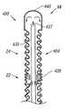
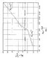
- FIG. 1is a graph showing the relationship between the Nusselt number (Nu) and the Reynolds number (Re) for air flowing through a long heated pipe at uniform wall temperature.
- FIG. 2is a front view of a first embodiment of a mixing-inducing heat transfer element according to the principles of the invention within an artery;
- FIG. 3is a more detailed front view of the heat transfer element of FIG. 1;
- FIG. 4is a front sectional view of the heat transfer element of FIG. 1;
- FIG. 5is a transverse sectional view of the heat transfer element of FIG. 1;
- FIG. 6is a front perspective view of the heat transfer element of FIG. 1 in use within a partially broken away blood vessel;
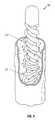
- FIG. 7is a partially broken away front perspective view of a second embodiment of a mixing-inducing heat transfer element according to the principles of the invention.
- FIG. 8is a transverse sectional view of the heat transfer element of FIG. 7;
- FIG. 9is a schematic representation of the invention being used to cool the brain of a patient.
- FIG. 10is a front sectional view of a guide catheter according to an embodiment of the invention which may be employed for applications of the heat transfer element according to the principles of the invention;
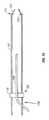
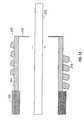
- FIG. 11is a front sectional view of a third embodiment of a catheter employing a heat transfer element according to the principles of the invention further employing a return tube/guide catheter;
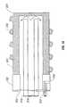
- FIG. 12is a front sectional view of a fourth embodiment of a catheter employing a heat transfer element according to the principles of the invention further employing a delivery catheter;
- FIG. 13is a front sectional view of the fourth embodiment of FIG. 12 further employing a working fluid catheter;
- FIG. 14is a front sectional view of a fifth embodiment of a catheter employing a heat transfer element according to the principles of the invention further employing a guide wire;
- FIG. 15is a front sectional view of a sixth embodiment of a catheter employing a heat transfer element according to the principles of the invention further employing a delivery lumen;
- FIG. 16is a front sectional view of an seventh embodiment of a catheter employing a heat transfer element according to the principles of the invention further employing a delivery lumen;
- FIG. 17is a front sectional view of an eighth embodiment of a catheter employing a heat transfer element according to the principles of the invention further employing a delivery lumen, this delivery lumen non-coaxial with the central body of the catheter;
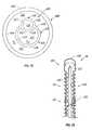
- FIG. 18is a front sectional view of a ninth embodiment of a catheter employing a heat transfer element according to the principles of the invention further employing multiple lumens;
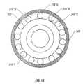
- FIG. 19is a cross-sectional view of the ninth embodiment of FIG. 18, taken along lines 19 — 19 of FIG. 18;
- FIG. 20is a front sectional view of a tenth embodiment of a catheter employing a heat transfer element according to the principles of the invention.
- FIG. 21is a front sectional view of a further embodiment of a catheter employing a heat transfer element according to the principles of the invention further employing a side-by-side lumen arrangement constructed in accordance with an embodiment of the invention;
- FIG. 22is a cross-sectional view of the catheter of FIG. 21 taken along line 22 — 22 of FIG. 21;
- FIG. 23is a front sectional view of a catheter employing a heat transfer element and lumen arrangement constructed in accordance with a further embodiment of the invention.
- FIG. 24is a front sectional view of a catheter employing a heat transfer element and lumen arrangement constructed in accordance with a still further embodiment of the invention.
- FIG. 25is a front sectional view of a another embodiment of a catheter employing a heat transfer element according to the principles of the invention further employing a side-by-side lumen arrangement constructed in accordance with another embodiment of the invention.
- FIG. 26is a cross-sectional view of the heat transfer element illustrated in FIG. 25 taken along line 26 — 26 of FIG. 25 .
- the temperature of a selected organmay be intravascularly regulated by a heat transfer element placed in the organ's feeding artery to absorb or deliver heat to or from the blood flowing into the organ. While the method is described with respect to blood flow into an organ, it is understood that heat transfer within a volume of tissue is analogous. In the latter case, heat transfer is predominantly by conduction.
- the heat transfermay cause either a cooling or a heating of the selected organ.
- a heat transfer element that selectively alters the temperature of an organshould be capable of providing the necessary heat transfer rate to produce the desired cooling or heating effect within the organ to achieve a desired temperature. If placed in the venous system, whole body cooling may also be effected.
- the heat transfer elementshould be small and flexible enough to fit within the feeding artery while still allowing a sufficient blood flow to reach the organ in order to avoid ischemic organ damage.
- Feeding arterieslike the carotid artery, branch off the aorta at various levels. Subsidiary arteries continue to branch off these initial branches.
- the internal carotid arterybranches off the common carotid artery near the angle of the jaw.
- the heat transfer elementis typically inserted into a peripheral artery, such as the femoral artery, using a guide catheter or guide wire, and accesses a feeding artery by initially passing though a series of one or more of these branches.
- the flexibility and size, e.g., the diameter, of the heat transfer elementare important characteristics. This flexibility is achieved as is described in more detail below.
- the common carotid arterysupplies blood to the head and brain.
- the internal carotid arterybranches off the common carotid artery to supply blood to the anterior cerebrum.
- the heat transfer elementmay be placed into the common carotid artery or into both the common carotid artery and the internal carotid artery.
- hypothermiaThe benefits of hypothermia described above are achieved when the temperature of the blood flowing to the brain is reduced to between 30° C. and 32° C.
- a typical brainhas a blood flow rate through each carotid artery (right and left) of approximately 250-375 cubic centimeters per minute (cc/min). With this flow rate, calculations show that the heat transfer element should absorb approximately 75-175 watts of heat when placed in one of the carotid arteries to induce the desired cooling effect. Smaller organs may have less blood flow in their respective supply arteries and may require less heat transfer, such as about 25 watts.
- the methodemploys conductive and convective heat transfers. Once the materials for the device and a working fluid are chosen, the conductive heat transfers are solely dependent on the temperature gradients. Convective heat transfers, by contrast, also rely on the movement of fluid to transfer heat. Forced convection results when the heat transfer surface is in contact with a fluid whose motion is induced (or forced) by a pressure gradient, area variation, or other such cause. In the case of arterial flow, the beating heart provides an oscillatory pressure gradient to force the motion of the blood in contact with the heat transfer surface.
- One of the aspects of the deviceuses turbulence to enhance this forced convective heat transfer.
- ⁇ overscore (h c +L ) ⁇is sometimes called the “surface coefficient of heat transfer” or the “convection heat transfer coefficient”.
- the magnitude of the heat transfer rate Q to or from the fluid flowcan be increased through manipulation of the above three parameters. Practical constraints limit the value of these parameters and how much they can be manipulated.
- the internal diameter of the common carotid arteryranges from 6 to 8 mm.
- the heat transfer element residing thereinmay not be much larger than 4 mm in diameter to avoid occluding the vessel.
- the length of the heat transfer elementshould also be limited. For placement within the internal and common carotid artery, the length of the heat transfer element is limited to about 10 cm. This estimate is based on the length of the common carotid artery, which ranges from 8 to 12 cm.
- the value of the surface area Sis limited by the physical constraints imposed by the size of the artery into which the device is placed.
- Surface featurescan be used to increase the surface area of the heat transfer element; however, these features alone generally cannot provide enough surface area enhancement to meet the required heat transfer rate to effectively cool the brain.
- the allowable surface temperature of the heat transfer elementis limited by the characteristics of blood.
- the blood temperatureis fixed at about 37° C., and blood freezes at approximately 0° C. When the blood approaches freezing, ice emboli may form in the blood which may lodge downstream, causing serious ischemic injury.
- reducing the temperature of the bloodalso increases its viscosity which results in a small decrease in the value of ⁇ overscore (h c +L ) ⁇ .
- Increased viscosity of the bloodmay furher result in an increase in the pressure drop within the artery, thus compromising the flow of blood to the brain.
- the heat transfer rate Q no-flow in the absence of fluid flowis proportional to ⁇ T, the temperature differential between the surface temperature T s of the heat transfer element and the free stream blood temperature T b times k, the diffusion constant, and is inversely proportion to distance D across which heat is being transferred.
- Nusselt numbers of 50-80have been found to be appropriate for selective cooling applications of various organs in the human body. Nusselt numbers are generally dependent on several other numbers: the Reynolds number, the Womersley number, and the Prandtl number.
- FIG. 1illustrates the dependency of the Nusselt number on the Reynolds number for a fluid flowing through a long duct, i.e., air flowing though a long heated pipe at a uniform wall temperature.
- FIG. 1illustrates this relationship for a different fluid through a different structure, the inventors of the present invention believe a similar relationship exists for blood flow through a blood vessel.
- FIG. 1illustrates that flow is laminar when the Reynolds number is below some number, in this case about 2100. In the range of Reynolds numbers between another set of numbers, in this case 2100 and 10,000, a transition from laminar to turbulent flow takes place. The flow in this regime is called transitional.
- the mixing caused by the heat transfer element of the present inventionproduces a flow that is at least transitional. At another Reynolds number, in the case above, about 10,000, the flow becomes fully turbulent.
- the type of flow that occursis important because in laminar flow through a duct, there is no mixing of warmer and colder fluid particles by eddy motion. Thus, the only heat transfer that takes place is through conduction. Since most fluids have small thermal conductivities, the heat transfer coefficients in laminar flow are relatively small. In transitional and turbulent flow, mixing occurs through eddies that carry warmer fluid into cooler regions and vice versa. Since the mixing motion, even if it is only on a small scale compared to fully turbulent flow, accelerates the transfer of heat considerably, a marked increase in the heat transfer coefficient occurs above a certain Reynolds number, which in the graph of FIG. 1 is about 2100. It can be seen from FIG. 1 that it is at approximately this point where the Nusselt number increases more dramatically. A different set of numbers may be measured for blood flow through an artery or vein. However, the inventors believe that a Nusselt number at least in the transitional region is important for enhanced heat transfer.
- Stirring-type mechanismswhich abruptly change the direction of velocity vectors, may be utilized to induce at least transitional flow, increasing the heat transfer rate by this eddy creation.
- the level of turbulence or mixing so createdis characterized by the turbulence intensity .
- Turbulence intensityis defined as the root mean square of the fluctuating velocity divided by the mean velocity.
- Such mechanismscan create high levels of turbulence intensity in the free stream, thereby increasing the heat transfer rate. This turbulence intensity should ideally be sustained for a significant portion of the cardiac cycle, and should ideally be created throughout the free stream and not just in the boundary layer.
- Turbulencedoes occur for a short period in the cardiac cycle anyway.
- the blood flowis turbulent during a small portion of the descending systolic flow. This portion is less than 20% of the period of the cardiac cycle.
- the heat transfer ratewill be enhanced during this short interval.
- the turbulence intensityis at least 0.05.
- the instantaneous velocity fluctuationsdeviate from the mean velocity by at least 5%. In some embodiments, lower fluctuations may be employed, such as 3% or even 2%.
- One type of mixing-inducing heat transfer elementwhich may be advantageously employed is a heat transfer element made of a high thermal conductivity material, such as metal.
- a high thermal conductivity materialincreases the heat transfer rate for a given temperature differential between the coolant within the heat transfer element and the blood. This facilitates the use of a higher temperature coolant within the heat transfer element, allowing safer coolants, such as water, to be used.
- Highly thermally conductive materials, such as metalstend to be rigid.
- Bellowsprovided a high degree of articulation that compensated for the intrinsic stiffness of the metal.
- the bellowsmay be replaced with a straight metal tube having a predetermined thickness to allow flexibility via bending of the metal.
- the bellowsmay be replaced with a polymer tube, e.g., a latex rubber tube, a plastic tube, or a flexible plastic corrugated tube.
- the device sizemay be minimized, e.g., less than 4 mm, to prevent blockage of the blood flowing in the vessel.
- the design of the heat transfer elementshould facilitate flexibility in an inherently inflexible material.
- FIG. 2is a perspective view of such a mixing-inducing heat transfer element within an artery. Transitional to turbulent flow would be found at point 114 , in the free stream area.
- the abrupt changes in flow directionare achieved through the use of a series of two or more heat transfer segments, each comprised of one or more helical ridges.
- FIG. 3is an elevation view of one embodiment of a heat transfer element 14 .
- the heat transfer element 14is comprised of a series of elongated, articulated segments or modules 20 , 22 , 24 . Three such segments are shown in this embodiment, but one or more such segments could be used.
- a first elongated heat transfer segment 20is located at the proximal end of the heat transfer element 14 .
- a mixing inducing exterior surface of the segment 20comprises four parallel helical ridges 28 with four parallel helical grooves 26 therebetween.
- One, two, three, or more parallel helical ridges 28could also be used.
- the helical ridges 28 and the helical grooves 26 of the heat transfer segment 20have a left hand twist, referred to herein as a counter-clockwise spiral or helical rotation, as they proceed toward the distal end of the heat transfer segment 20 .
- the first heat transfer segment 20is coupled to a second elongated heat transfer segment 22 by a first tube section 25 , which provides flexibility.
- the second heat transfer segment 22comprises one or more helical ridges 32 with one or more helical grooves 30 therebetween.
- the ridges 32 and grooves 30have a right hand, or clockwise, twist as they proceed toward the distal end of the heat transfer segment 22 .
- the second heat transfer segment 22is coupled to a third elongated heat transfer segment 24 by a second tube section 27 .
- the third heat transfer segment 24comprises one or more helical ridges 36 with one or more helical grooves 34 therebetween.
- the helical ridge 36 and the helical groove 34have a left hand, or counter-clockwise, twist as they proceed toward the distal end of the heat transfer segment 24 .
- successive heat transfer segments 20 , 22 , 24 of the heat transfer element 14alternate between having clockwise and counterclockwise helical twists.
- the actual left or right hand twist of any particular segmentis immaterial, as long as adjacent segments have opposite helical twist.
- a heat transfer elementmay be comprised of one, two, three, or more heat transfer segments.
- the tube sections 25 , 27are formed from seamless and nonporous materials, such as metal, and therefore are impermeable to gas, which can be particularly important, depending on the type of working fluid that is cycled through the heat transfer element 14 .
- the structure of the tube sections 25 , 27allows them to bend, extend and compress, which increases the flexibility of the heat transfer element 14 so that it is more readily able to navigate through blood vessels.
- the tube sections 25 , 27are also able to tolerate cryogenic temperatures without a loss of performance.
- the tube sections 25 , 27may have a predetermined thickness of their walls, such as between about 0.5 and 0.8 mils. The predetermined thickness is to a certain extent dependent on the diameter of the overall tube.
- tube sections 25 , 27may be formed from a polymer material such as rubber, e.g., latex rubber.
- the exterior surfaces of the heat transfer element 14can be made from metal except in flexible joint embodiments where the surface may be comprised of a polymer material.
- the metalmay be a very high thermal conductivity material such as nickel, thereby facilitating efficient heat transfer.
- other metalssuch as stainless steel, titanium, aluminum, silver, copper and the like, can be used, with or without an appropriate coating or treatment to enhance biocompatibility or inhibit clot formation.
- Suitable biocompatible coatingsinclude, e.g., gold, platinum or polymer paralyene.
- the heat transfer element 14may be manufactured by plating a thin layer of metal on a mandrel that has the appropriate pattern. In this way, the heat transfer element 14 may be manufactured inexpensively in large quantities, which is an important feature in a disposable medical device.
- the heat transfer element 14may dwell within the blood vessel for extended periods of time, such as 24-48 hours or even longer, it may be desirable to treat the surfaces of the heat transfer element 14 to avoid clot formation.
- One means by which to prevent thrombus formationis to bind an antithrombogenic agent to the surface of the heat transfer element 14 .
- heparinis known to inhibit clot formation and is also known to be useful as a biocoating.
- the surfaces of the heat transfer element 14may be bombarded with ions such as nitrogen. Bombardment with nitrogen can harden and smooth the surface and thus prevent adherence of clotting factors to the surface.
- FIG. 4is a longitudinal sectional view of the heat transfer element 14 , taken along line 4 — 4 in FIG. 3 . Some interior contours are omitted for purposes of clarity.
- An inner tube 42creates an inner coaxial lumen 40 and an outer coaxial lumen 46 within the heat transfer element 14 .
- a working fluidsuch as saline or other aqueous solution may be circulated through the heat transfer element 14 . Fluid flows up a supply catheter into the inner coaxial lumen 40 . At the distal end of the heat transfer element 14 , the working fluid exits the inner coaxial lumen 40 and enters the outer lumen 46 .
- the tube 42may be formed as an insulating divider to thermally separate the inner lumen 40 from the outer lumen 46 .
- insulationmay be achieved by creating longitudinal air channels in the wall of the insulating tube 42 .
- the insulating tube 42may be constructed of a non-thermally conductive material like polytetrafluoroethylene or some other polymer.
- the same mechanisms that govern the heat transfer rate between the exterior surface 37 of the heat transfer element 14 and the bloodalso govern the heat transfer rate between the working fluid and the interior surface 38 of the heat transfer element 14 .
- the heat transfer characteristics of the interior surface 38are particularly important when using water, saline or other fluid which remains a liquid as the coolant.
- Other coolantssuch as freon undergo nucleate boiling and create turbulence through a different mechanism.
- Salineis a safe coolant because it is non-toxic, and leakage of saline does not result in a gas embolism, which could occur with the use of boiling refrigerants. Since turbulence or mixing in the coolant is enhanced by the shape of the interior surface 38 of the heat transfer element 14 , the coolant can be delivered to the heat transfer element 14 at a warmer temperature and still achieve the necessary heat transfer rate.
- the catheter shaft diametercan be made smaller.
- the enhanced heat transfer characteristics of the interior surface of the heat transfer element 14also allow the working fluid to be delivered to the heat transfer element 14 at lower flow rates and lower pressures. High pressures may make the heat transfer element stiff and cause it to push against the wall of the blood vessel, thereby shielding part of the exterior surface 37 of the heat transfer element 14 from the blood. Because of the increased heat transfer characteristics achieved by the alternating helical ridges 28 , 32 , 36 , the pressure of the working fluid may be as low as 5 atmospheres, 3 atmospheres, 2 atmospheres or even less than 1 atmosphere.
- FIG. 5is a transverse sectional view of the heat transfer element 14 , taken at a location denoted by the line 5 — 5 in FIG. 3 .
- FIG. 5illustrates a five-lobed embodiment
- FIG. 3illustrates a four-lobed embodiment. As mentioned earlier, any number of lobes might be used.
- the inner coaxial lumen 40is defined by the insulating coaxial tube 42 .
- the outer lumen 46is defined by the exterior surface of the insulating coaxial tube 42 and the interior surface 38 of the heat transfer element 14 .
- the helical ridges 32 and helical grooves 30may be seen in FIG. 5 .
- the depth of the grooves, d imay be greater than the boundary layer thickness which would have developed if a cylindrical heat transfer element were introduced.
- the depth of the invaginations, d imay be approximately equal to 1 mm if designed for use in the carotid artery.
- FIG. 5shows four ridges and four grooves, the number of ridges and grooves may vary. Thus, heat transfer elements with 1, 2, 3, 4, 5, 6, 7, 8 or more ridges are specifically contemplated.
- FIG. 6is a perspective view of a heat transfer element 14 in use within a blood vessel, showing only one helical lobe per segment for purposes of clarity.
- the first helical heat transfer segment 20induces a counter-clockwise rotational inertia to the blood.
- an unstable shear layeris produced that causes mixing within the blood.
- the rotational direction of the inertiais again reversed. The sudden changes in flow direction actively reorient and randomize the velocity vectors, thus ensuring mixing throughout the bloodstream.
- the velocity vectors of the bloodbecome more random and, in some cases, become perpendicular to the axis of the artery.
- additional mixingis induced and sustained throughout the duration of each pulse through the same mechanisms described above.
- the heat transfer element 14creates a turbulence intensity greater than about 0.05.
- the turbulence intensitymay be greater than 0.05, 0.06, 0.07 or up to 0.8 or 0.20 or greater.
- the heat transfer element 14has been designed to address all of the design criteria discussed above.
- the heat transfer element 14is flexible and is made of a highly conductive material. The flexibility is provided by a segmental distribution of tube sections 25 , 27 which provide an articulating mechanism. The tube sections have a predetermined thickness which provides sufficient flexibility.
- the exterior surface area 37has been increased through the use of helical ridges 28 , 32 , 36 and helical grooves 26 , 30 , 34 . The ridges also allow the heat transfer element 14 to maintain a relatively a traumatic profile, thereby minimizing the possibility of damage to the vessel wall.
- the heat transfer element 14has been designed to promote mixing both internally and externally.
- the modular or segmental designallows the direction of the invaginations to be reversed between segments.
- the alternating helical rotationscreate an alternating flow that results in a mixing of the blood in a manner analogous to the mixing action created by the rotor of a washing machine that switches directions back and forth. This mixing action is intended to promote a high level of mixing or turbulent kinetic energy to enhance the heat transfer rate.
- the alternating helical designalso causes beneficial mixing, or turbulent kinetic energy, of the working fluid flowing internally.
- FIG. 7is a cut-away perspective view of an alternative embodiment of a heat transfer element 50 .
- An external surface 52 of the heat transfer element 50is covered with a series of axially staggered protrusions 54 .
- the staggered nature of the outer protrusions 54is readily seen with reference to FIG. 8 which is a transverse cross-sectional view taken at a location denoted by the line 8 — 8 in FIG. 7 .
- the height, d pof the staggered outer protrusions 54 is greater than the thickness of the boundary layer which would develop if a smooth heat transfer element had been introduced into the blood stream.
- the bloodflows along the external surface 52 , it collides with one of the staggered protrusions 54 and a turbulent wake flow is created behind the protrusion.
- a turbulent wake flowis created behind the protrusion.
- the blooddivides and swirls along side of the first staggered protrusion 54
- its turbulent wakeencounters another staggered protrusion 54 within its path preventing the re-lamination of the flow and creating yet more mixing.
- the velocity vectorsare randomized and mixing is created not only in the boundary layer but also throughout the free stream. As is the case with the preferred embodiment, this geometry also induces a mixing effect on the internal coolant flow.
- a working fluidis circulated up through an inner coaxial lumen 56 defined by an insulating coaxial tube 58 to a distal tip of the heat transfer element 50 .
- the working fluidthen traverses an outer coaxial lumen 60 in order to transfer heat to the exterior surface 52 of the heat transfer element 50 .
- the inside surface of the heat transfer element 50is similar to the exterior surface 52 , in order to induce mixing flow of the working fluid.
- the inner protrusionscan be aligned with the outer protrusions 54 , as shown in FIG. 8, or they can be offset from the outer protrusions 54 , as shown in FIG. 7 .
- FIG. 9is a schematic representation of an embodiment of the invention being used to cool the brain of a patient.
- a selective organ hypothermia apparatus shown in FIG. 9includes a working fluid supply 10 , preferably supplying a chilled liquid such as water, alcohol or a halogenated hydrocarbon, a supply catheter 12 and the heat transfer element 14 .
- the supply catheter 12has a coaxial construction.
- An inner coaxial lumen within the supply catheter 12receives coolant from the working fluid supply 10 .
- the coolanttravels the length of the supply catheter 12 to the heat transfer element 14 which serves as the cooling tip of the catheter.
- the coolantexits the insulated interior lumen and traverses the length of the heat transfer element 14 in order to decrease the temperature of the heat transfer element 14 .
- the coolantthen traverses an outer lumen of the supply catheter 12 so that it may be disposed of or recirculated.
- the supply catheter 12is a flexible catheter having a diameter sufficiently small to allow its distal end to be inserted percutaneously into an accessible artery such as the femoral artery of a patient as shown in FIG. 9 .
- the supply catheter 12is sufficiently long to allow the heat transfer element 14 at the distal end of the supply catheter 12 to be passed through the vascular system of the patient and placed in the internal carotid artery or other small artery.
- the devicemay also be placed in the venous system to cause total body cooling.
- the device's heliceswhich are one way of increasing the surface area as well as to induce mixing or turbulence, enhance heat transfer.
- working fluid supply 10is shown as an exemplary cooling device, other devices and working fluids may be used.
- freon, perflourocarbon, water, or salinemay be used, as well as other such coolants.
- the heat transfer elementcan absorb or provide over 75 Watts of heat to the blood stream and may absorb or provide as much as 100 Watts, 150 Watts, 170 Watts or more.
- a heat transfer element with a diameter of 4 mm and a length of approximately 10 cm using ordinary saline solution chilled so that the surface temperature of the heat transfer element is approximately 5° C. and pressurized at 2 atmospherescan absorb about 100 Watts of energy from the bloodstream.
- Smaller geometry heat transfer elementsmay be developed for use with smaller organs which provide 60 Watts, 50 Watts, 25 Watts or less of heat transfer. For venous cooling, as much as or more than 250 Watts may be extracted.
- the patientis initially assessed, resuscitated, and stabilized.
- the procedureis carried out in an angiography suite or surgical suite equipped with fluoroscopy.
- a carotid duplex (Doppler/ultrasound) scancan quickly and non-invasively make this determination.
- the ideal location for placement of the catheteris in the left carotid so this may be scanned first. If disease is present, then the right carotid artery can be assessed. This test can be used to detect the presence of proximal common carotid lesions by observing the slope of the systolic upstroke and the shape of the pulsation. Although these lesions are rare, they could inhibit the placement of the catheter.
- Peak blood flow velocities in the internal carotidcan determine the presence of internal carotid artery lesions. Although the catheter is placed proximally to such lesions, the catheter may exacerbate the compromised blood flow created by these lesions. Peak systolic velocities greater that 130 cm/sec and peak diastolic velocities>100 cm/sec in the internal indicate the presence of at least 70% stenosis. Stenosis of 70% or more may warrant the placement of a stent to open up the internal artery diameter.
- the ultrasoundcan also be used to determine the vessel diameter and the blood flow and the catheter with the appropriately sized heat transfer element are selected.
- the patient's inguinal regionis sterilely prepped and infiltrated with lidocaine.
- the femoral arteryis cannulated and a guide wire may be inserted to the desired carotid artery. Placement of the guide wire is confirmed with fluoroscopy.
- An angiographic cathetercan be fed over the wire and contrast media injected into the artery to further to assess the anatomy of the carotid.
- the femoral arteryis cannulated and a 10-12.5 french (f) introducer sheath is placed.
- a guide catheteris placed into the desired common carotid artery. If a guiding catheter is placed, it can be used to deliver contrast media directly to further assess carotid anatomy.
- a 10 f-12 f (3.3-4.0 mm) (approximate) cooling catheteris subsequently filled with saline and all air bubbles are removed.
- the cooling catheteris placed into the carotid artery via the guiding catheter or over the guidewire. Placement is confirmed with fluoroscopy.
- the cooling catheteris connected to a refrigerated pump circuit also filled with saline and free from air bubbles.
- Coolingis initiated by starting the refrigerated pump circuit.
- the saline within the cooling catheteris circulated at 3-8 cc/sec.
- the salinetravels through the refrigerated pump circuit and is cooled to approximately 1° C.
- the salinesubsequently enters the cooling catheter where it is delivered to the heat transfer element.
- the salineis warmed to approximately 5-7° C. as it travels along the inner lumen of the catheter shaft to the end of the heat transfer element.
- the salinethen flows back through the heat transfer element in contact with the inner metallic surface.
- the salineis further warmed in the heat transfer element to 12-15° C., and in the process, heat is absorbed from the blood, cooling the blood to 30° C. to 32° C.
- the warmed salinetravels back down the outer lumen of the catheter shaft and back to the chilled water bath where it is cooled to 1° C.
- the pressure drops along the length of the circuitare estimated to be, e.g., 6 atmospheres.
- the coolingcan be adjusted by increasing or decreasing the flow rate of the saline, or by changing the temperature of the saline. Monitoring of the temperature drop of the saline along the heat transfer element will allow the flow to be adjusted to maintain the desired cooling effect.
- the catheteris left in place to provide cooling for up to or more than 12 to 24 hours.
- warm salinecan be circulated to promote warming of the brain at the end of the procedure.
- the inventionmay also be used in combination with other techniques.
- one technique employed to place working lumens or catheters in desired locationsemploys guide catheters, as mentioned above.
- a guide catheter 102is shown which may be advantageously employed in the invention.
- the guide catheter 102has a soft tapered tip 104 and a retaining flange 124 at a distal end 101 .
- the soft tapered tip 104allows an a traumatic entrance of the guide catheter 102 into an artery as well as a sealing function as is described in more detail below.
- the retaining flange 124may be a metallic member adhered to the guide catheter interior wall or may be integral with the material of the tube.
- the retaining flange 124further has a sealing function described in more detail below.
- the guide catheter 102may have various shapes to facilitate placement into particular arteries. In the case of the carotid artery, the guide catheter 102 may have the shape of a hockey stick.
- the guide catheter 102may include a Pebax® tube with a Teflon® liner.
- the Teflon® linerprovides sufficient lubricity to allow minimum friction when components are pushed through the tube.
- a metal wire braidmay also be employed between the Pebax® tube and the Teflon® liner to provide torqueability of the guide catheter 102 .
- a number of proceduresmay be performed with the guide catheter 102 in place within an artery or vein.
- a stentmay be disposed across a stenotic lesion in the internal carotid artery. This procedure involves placing a guide wire through the guide catheter 102 and across the lesion. A balloon catheter loaded with a stent is then advanced along the guide wire. The stent is positioned across the lesion. The balloon is expanded with contrast, and the stent is deployed intravascularly to open up the stenotic lesion. The balloon catheter and the guide wire may then be removed from the guide catheter.
- the guide cathetermay be employed to transfer contrast for diagnosis of bleeding or arterial blockage, such as for angiography.
- the samemay further be employed to deliver various drug therapies, e.g., to the brain.
- Such therapiesmay include delivery of thrombolytic drugs that lyse clots lodged in the arteries of the brain.
- a proximal end 103 of the guide catheter 102has a male luer connector for mating with a y-connector 118 attached to a supply tube 108 .
- the supply tube 108may include a braided Pebax® tube or a polyimide tube.
- the y-connector 118connects to the guide catheter 102 via a male/female luer connector assembly 116 .
- the y-connector 118allows the supply tube 108 to enter the assembly and to pass through the male/female luer connector assembly 116 into the interior of the guide catheter 102 .
- the supply tube 108may be disposed with an outlet at its distal end.
- the outlet of the supply tube 108may also be used to provide a working fluid to the interior of a heat transfer element 110 .
- the guide catheter 102may be employed as the return tube for the working fluid supply in this aspect of the invention.
- a heat transfer element 110is delivered to the distal end 101 of the guide catheter 102 as is shown in FIG. 11 .
- the heat transfer element 110is shown, nearly in a working location, in combination with the return tube/guide catheter 102 .
- the heat transfer element 110is shown near the distal end 101 of the return tube/guide catheter (“RTGC”) 102 .
- the heat transfer element 110may be kept in place by a flange 106 on the heat transfer element 110 that abuts the retaining flange 124 on the RTGC 102 .
- Flanges 124 and 106may also employ o-rings such as an o-ring 107 shown adjacent to the flange 106 .
- Other such sealing mechanisms or designsmay also be used. In this way, the working fluid is prevented from leaking into the blood.
- the supply tube 108may connect to the heat transfer element 110 (the connection is not shown) and may be employed to push the heat transfer element 110 through the guide catheter 102 .
- the supply tubeshould have sufficient rigidity to accomplish this function.
- a guide wiremay be employed having sufficient rigidity to push both the supply tube 108 and the heat transfer element 110 through the guide catheter 102 .
- a strut 112may be employed on a distal end of the supply tube 108 .
- the strut 112may have a window providing an alternative path for the flowing working fluid.
- the heat transfer element 110may employ any of the forms disclosed above, as well as variations of those forms.
- the heat transfer element 110may employ alternating helical ridges separated by flexible joints, the ridges creating sufficient mixing to enhance heat transfer between a working fluid and blood in the artery.
- the heat transfer element 110may be inflatable and may have sufficient surface area such that the heat transfer due to conduction alone is sufficient to provide the requisite heat transfer. Details of the heat transfer element 110 are omitted in FIG. 11 for clarity.
- FIG. 12shows an alternate embodiment of the invention in which a heat transfer element 204 employs an internal supply catheter 216 .
- the heat transfer element 204is shown with mixing-inducing invaginations 218 located thereon. Similar invaginations may be located in the interior of the heat transfer element 204 but are not shown for clarity. Further, it should be noted that the heat transfer element 204 is shown with merely four invaginations. Other embodiments may employ multiple elements connected by flexible joints as is disclosed above. A single heat transfer element is shown in FIG. 12 merely for clarity.
- a return supply catheter 202is shown coupled to the heat transfer element 204 .
- the return supply cathetermay be coupled to the heat transfer element 204 in known fashion, and may provide a convenient return path for working fluid as may be provided to the heat transfer element 204 to provide temperature control of a flow or volume of blood.
- a delivery catheter 216is also shown in FIG. 12 .
- the delivery catheter 216may be coupled to a y-connector at its proximal end in the manner disclosed above.
- the delivery catheter 216may be freely disposed within the interior of the return supply catheter 202 except where it is restrained from further longitudinal movement (in one direction) by a retaining flange 210 disposed at the distal end 208 of the heat transfer element 204 .
- the delivery catheter 216may be made sufficiently flexible to secure itself within retaining flange 210 , at least for a short duration.
- the delivery catheter 216may have a delivery outlet 212 at a distal end to allow delivery of a drug or other such material for therapeutic purposes.
- a radioopaque fluidmay be dispensed for angiography or a thrombolytic drug for thrombolytic applications.
- the delivery cathetermay be pulled upstream of the retaining flange 210 , exposing an annular hole in fluid communication with the return supply catheter 202 .
- the return supply catheter 202may then be used to drain the volume adjacent the retaining flange 210 .
- the assemblymay also perform temperature control of blood in the artery where the same is located. Such temperature control procedures may be performed, e.g., before or after procedures involving the delivery catheter 216 .
- a working fluid catheter 222is disposed within the return supply catheter 202 and the heat transfer element 204 .
- the working fluid cathetermay be freely disposed within the interior of the return supply catheter 202 and may further be coupled to a y-connector at its proximal end in the manner disclosed above.
- the working fluid catheter 222may further be made sufficiently flexible to secure itself within retaining flange 210 , at least for a short duration.
- the working fluid catheter 222may have a plurality of outlets 214 to allow delivery of a working fluid.
- the outlets 214are located near the distal end 224 of the working fluid catheter 222 but somewhat upstream. In this way, the outlets 214 allow dispensation of a working fluid into the interior of the heat transfer element 204 rather than into the blood stream.
- the working fluid catheter 222may also be insulated to allow the working fluid to maintain a desired temperature without undue heat losses to the walls of the working fluid catheter 222 .
- a guide wire 232is shown disposed within the interior of the heat transfer element 204 .
- the heat transfer element 204may conveniently use the hole defined by retaining flange 210 to be threaded onto the guide wire 232 .
- Numerous other therapiesmay then employ the return supply catheter and heat transfer element as a “guide catheter”.
- various laser and ultrasound ablation cathetersmay be disposed within, as well as microcatheters. In this way, these therapeutic techniques may be employed at nearly the same time as therapeutic temperature control, including, e.g., neuroprotective cooling.
- an additional lumenwas disclosed above in connection with passing a variety of treatments through the guide catheter.
- an additional lumenmay be employed to transfer contrast for diagnosis of bleeding or arterial blockage, such as for angiography.
- Such an additional lumenmay be defined by a drug delivery catheter which forms a part of the overall catheter assembly. The same may be employed to deliver various drug therapies, e.g., to the brain.
- the use of an additional lumenwas further mentioned in connection with expansion of a balloon that may be used to occlude a drug delivery lumen outlet.
- FIG. 15depicts an implementation of an embodiment of the invention employing just such a third lumen.
- a third lumen 316is a small central lumen defined by a drag delivery catheter substantially parallel to the supply and return catheters.
- a return catheter 302 defining an outlet lumen 320is coupled to a heat transfer element 304 as before.
- the heat transfer element 304may have mixing or turbulence-inducing invaginations 306 thereon.
- an inlet lumen 318defined by a supply catheter 310 .
- the inlet lumen 318may be used to deliver a working fluid to the interior of the heat transfer element 304 .
- the outlet lumen 320may be used to return or exhaust the working fluid from the heat transfer element 304 . As above, their respective functions may also be reversed.
- the radius of the return cathetermay be greater or less (in the case where their roles are reversed) than the radius of the supply catheter.
- the working fluidmay be used to heat or cool the heat transfer element which in turn heats or cools the fluid surrounding the heat transfer element.
- a drug delivery catheter 312defines the third lumen 316 and as shown may be coaxial with the inlet lumen 318 and the outlet lumen 320 .
- the delivery catheter 312may be also be off-axis or non-coaxial with respect to the inlet lumen 318 and the outlet lumen 320 .
- the drug delivery cathetermay be a lumen 316 ′ within the return catheter and may be further defined by a catheter wall 312 ′.
- the drug delivery cathetermay be a lumen 316 ′′ adjacent to and parallel to the return catheter and may be further defined by a catheter wall 312 ′′.
- more than one lumenmay be provided within the return catheter to allow delivery of several types of products, e.g., thrombolytics, saline solutions, etc.
- the supply cathetermay also be used to define the drug delivery catheter.
- the drug delivery cathetermay be substantially parallel to the return catheter or supply catheter or both, or may alternatively be at an oblique angle.
- the drug delivery catheterincludes an outlet at a distal end thereof.
- the outletmay be distal or proximal of the distal end of the return or supply catheters.
- the outletmay be directed parallel to the return and supply catheters or may alternatively be directed transverse of the return and supply catheters.
- the devicemay be inserted in a selected feeding vessel in the vascular system of a patient.
- the devicemay be inserted in an artery which feeds a downstream organ or which feeds an artery which, in turn, feeds a downstream organ.
- the drug delivery catheter lumenmay be used to deliver a drug, liquid, enzyme or other material to the approximate location of the heat transfer element. Such delivery may occur before, after, or contemporaneous with heat transfer to or from the blood.
- materialse.g., drugs, liquids, enzymes, which operate at temperatures other than normal body temperature may be used by first altering the local blood temperature with the heat transfer element and then delivering the temperature specific material, e.g., a temperature-specific thrombolytic, which then operates at the altered temperature.
- temperature specific materiale.g., a temperature-specific thrombolytic
- such “third” lumensmay be used to remove particles, debris, or other desired products from the blood stream.
- FIGS. 18 and 19show another embodiment of the invention that is related to the embodiment of FIG. 16 .
- several additional sealed lumensare disposed in the return catheter. Some of the lumens may be for drug delivery and others may be used to enhance mixing in a manner described below.
- the sealed lumensare in pressure communication with a supply of air to inflate the same.
- a return catheter 302 ′has one lumen 316 ′′′C as shown for drug delivery.
- Another, lumen 316 ′′′Iis shown which may be employed to alter the geometry and shape of the overall catheter. That is, inflating lumen 316 ′′′I causes the lumen to expand in the same way that inflating a balloon causes it to expand.
- inflatable lumens 316 ′′′A-B and 316 ′′′D-Nmay be distributed in a substantially symmetric fashion around the circumference of the catheter for a uniform inflation if desired. Of course, less distortion under inflation may occur at or adjacent lumens such as 316 ′′′C used for drug delivery, as these do not inflate.
- the inflatable lumens 316 ′′′A-B and 316 ′′′D-Nmay be caused to inflate under influence of, e.g., an air compressor with a variable air delivery flow. Rapid pulses of air may be used to inflate the lumens 316 ′′′A-B and 316 ′′′D-N in a rapid and repeated fashion.
- the outer walls defining these lumensmove rapidly into and out of the bloodstream around the catheter, inducing turbulence.
- the amplitude of the vibrationsis large enough to move the outer walls defining the lumens out of the boundary layer and into the free stream of blood. This effect produces mixing which is used to enhance heat transfer.
- the area of appropriate wall thickness to allow for inflationneed only be at, near, or adjacent the portion of the return catheter exterior wall adjacent the heat transfer element.
- the return catheter wallonly requires substantial reduction near the heat transfer element.
- the remainder of the catheter wallmay remain thick for strength and durability.
- the supply catheter 310may be constructed such that the same does not contact the interior of the distal end 308 of the heat transfer element, which may cause a subsequent stoppage of flow of the working fluid. Such construction may be via struts located in the return catheter 302 that extend radially inwards and secure the supply catheter 310 from longitudinal translations. Alternatively, struts may extend longitudinally from the distal end of the supply catheter 310 and hold the same from contacting the heat transfer element. This construction is similar to strut 112 shown in FIG. 11 .
- FIG. 20shows an alternate method of accomplishing this goal.
- a heat transfer element 304 ′has an orifice 326 at a distal end 308 .
- a supply catheter 310 ′is equipped with a drag delivery catheter 312 ′ extending coaxially therein.
- the drug delivery catheter 312may be formed of a solid material integral with supply catheter 310 ′, or the two may be bonded after being constructed of separate pieces, or the two may remain separate during use, with a friction fit maintaining their positions with respect to each other.
- the supply catheter 310 ′is “in position” when a tapered portion 324 of the same is lodged in the hole 326 in the heat transfer element 304 ′.
- the tapered portion 324should be lodged tightly enough to cause a strong friction fit so that working fluid does not leak through the hole 326 . However, the tapered portion 324 should be lodged loosely enough to allow the supply catheter 310 ′ to be removed from the heat transfer element 304 ′ if continued independent use of the return catheter is desired.
- the supply catheter 310 ′has a plurality of outlets 322 .
- Outlets 322are provided at points generally near or adjacent the distal end of the supply catheter 310 ′.
- the outletsare provided such that, when the supply catheter 310 ′ is in position, the outlets generally face the heat transfer element 304 ′.
- the working fluidemerging from the outlets 322 , more directly impinges on the interior wall of the heat transfer element 304 ′.
- the working fluidexits the interior of the supply catheter and flows into a volume defined by the exterior of the supply catheter and the interior of the heat transfer element.
- FIG. 20does not show the invaginations on the interior wall of the heat transfer element 304 ′. However, it will be understood that such invaginations may be present and may allow for enhanced heat transfer in combination with the emerging working fluid.
- FIGS. 10, 12 , and 14 - 20various types of catheter assemblies employing drug delivery catheters are described.
- a therapymay be performed in which the distal end of the catheter is embedded into a clot to be dissolved.
- An enzyme solutionsuch as a warm or cool enzyme solution, may then be sent directly into the clot to locally enhance the fibrinolytic activity.
- the cathetermay be placed as described above. In this procedure, however, the catheter is placed such that the tip of the protruding drug delivery catheter touches, is substantially near, or becomes embedded within the clot.
- An enzyme solution or other such drugis then delivered down the drug delivery catheter directly into the clot or into the volume of blood surrounding the clot.
- the enzyme solutionmay include tPA, streptokinase, urokinase, pro-urokinase, combinations thereof, and may be heated to enhance fibrinolytic activity.
- the solutionmay be a simple heated saline solution. The heated saline solution warms the clot, or the volume surrounding the clot, again leading to enhanced fibrinolytic activity.
- the distal tip of the drug delivery catheteris substantially protruding, or is distal, from the remainder of the catheter assembly.
- the distal tipmay be disposed adjacent to or within a clot without being obstructed by the remainder of the catheter assembly.
- the heat transfer element 110may employ any of the forms disclosed above, as well as variations of these forms.
- the heat transfer element 110may employ alternating helical ridges separated by flexible joints, the ridges creating sufficient mixing and/or surface area to enhance heat transfer between a working fluid and blood in the artery or vein.
- the heat transfer element 110may be inflatable and may have sufficient surface area such that the heat transfer due to conduction alone is sufficient to provide the requisite heat transfer. Details of the heat transfer element 110 are omitted in FIG. 11 for clarity.
- the catheter 400includes an elongated catheter body 402 with a heat transfer element 404 located at a distal portion 406 of the catheter body 402 .
- the catheter 400includes a multiple lumen arrangement 408 to deliver fluid to and from an interior 410 of the heat transfer element 404 and allow the catheter 400 to be placed into a blood vessel over a guidewire.
- the heat transfer element 404includes turbulence-inducing invaginations 412 located on an exterior surface 414 . Similar invaginations may be located on an interior surface 416 of the heat transfer element 404 , but are not shown for clarity.
- heat transfer element 404is shown with only four invaginations 412 .
- Other embodimentsmay employ multiple elements connected by flexible joints or bellows as disclosed above.
- a single heat transfer elementis shown in FIG. 21 merely for clarity.
- any of the other heat-transfer elements described hereinmay replace heat transfer element 406 .
- the multi-lumen arrangementmay be used to deliver fluid to and from the interior of an operative element(s) other than a heat-transfer-element such as, but without limitation, a catheter balloon, e.g., a dilatation balloon.
- the catheter 400includes an integrated elongated multiple lumen member such as a bi-lumen member 418 having a first lumen member 420 and a second lumen member 422 .
- the bi-lumen member 418has a substantially figure-eight cross-sectional shape (FIG. 22) and an outer surface 419 with the same general shape.
- the first lumen member 420includes an interior surface 424 defining a first lumen or guide wire lumen 426 having a substantially circular cross-sectional shape.
- the interior surface 424may be coated with a lubricious material to facilitate the sliding of the catheter 400 over a guidewire.
- the first lumen member 420further includes a first exterior surface 428 and a second exterior surface 430 .
- the first lumen 426is adapted to receive a guide wire for placing the catheter 400 into a blood vessel over the guidewire in a well-known manner.
- the guide wire lumen 426is not coaxial with the catheter body 402 .
- the guide wire lumen 426may be coaxial with the catheter body 402 .
- the second lumen member 422includes a first interior surface 432 and a second interior surface 434 , which is the same as the second exterior surface 430 of the first lumen member 420 , that together define a second lumen or supply lumen 436 having a substantially luniform cross-sectional shape.
- the second lumen member 422further includes an exterior surface 438 .
- the second lumen 436has a cross-sectional area A 2 .
- the second lumen 436is adapted to supply working fluid to the interior of the heat transfer element 404 to provide temperature control of a flow or volume of blood in the manner described above.
- the second lumen member 422terminates short of a distal end 440 of the catheter 400 , leaving sufficient space for the working fluid to exit the supply lumen 436 so it can contact the interior surface 416 of the heat transfer element 404 for heat transfer purposes.
- a single supply lumen member 435may include one or more outlet openings 437 adjacent the distal end 440 of the catheter 400 and one or more outlet openings 439 adjacent a mid-point along the interior length of the heat transfer element 404 . This arrangement improves the heat transfer characteristics of the heat-transfer element 404 because fresh working fluid at the same temperature is delivered separately to each segment 22 , 24 of the interior of the heat-transfer element 404 instead of in series.
- heat transfer segments 22 , 24are shown, it will be readily apparent that a number of heat transfer segments other than two, e.g., one, three, four, etc., may be used.
- one or more openings 437 in the distal portion of the heat transfer element 404may be located anywhere along the interior length of the heat transfer element 404 proximal to the distal portion.
- first and second supply lumen members 441 , 443define respective first and second supply lumens 445 , 447 for supplying working fluid to the interior of the heat transfer element 404 .
- the first supply lumen 441terminates just short of the distal end 440 of the catheter 400 to deliver working fluid at the distal portion of the heat transfer element 404 .
- the second supply lumen 443terminates short of the distal portion of the catheter 400 , for example, at approximately a mid-length point along the interior of the heat transfer element 404 for delivering working fluid to the second heat transfer segment 22 .
- the second lumen member 443may terminate anywhere along the interior length of the heat transfer element 404 proximal to the distal portion of the heat transfer element 404 . Further, a number of supply lumens 443 greater than two may terminate along the interior length of the heat transfer element 404 for delivering a working fluid at a variety of points along the interior length of the heat transfer element 404 .
- the bi-lumen member 418is preferably extruded from a material such as polyurethane or Pebax. In an embodiment of the invention, the bi-lumen member is extruded simultaneously with the catheter body 402 . In an alternative embodiment of the invention, the first lumen member 420 and second lumen member 422 are formed separately and welded or fixed together.
- a third lumen or return lumen 442provides a convenient return path for working fluid.
- the third lumen 442is substantially defined by the interior surface 416 of the heat transfer element 404 , an interior surface 444 of the catheter body 402 , and the exterior surface 419 of the bi-lumen member 418 .
- the inventorshave determined that the working fluid pressure drop through the lumens is minimized when the third lumen 442 has a hydraulic diameter D 3 that is equal to 0.75 of the hydraulic diameter D 2 of the second lumen 436 .
- the pressure drop that occurs when the ratio of the hydraulic diameter D 3 to the hydraulic diameter D 2is substantially equal to 0.75 , i.e., 0.75 ⁇ 0.10, works well.
- the hydraulic diameter D of a lumenis equal to four times the cross-sectional area of the lumen divided by the wetted perimeter.
- the wetted perimeteris the total perimeter of the region defined by the intersection of the fluid path through the lumen and a plane perpendicular to the longitudinal axis of the lumen.
- the wetted perimeter for the return lumen 442would include an inner wetted perimeter (due to the outer surface 419 of the bi-lumen member 418 ) and an outer wetted perimeter (due to the interior surface 444 of the catheter body 402 ).
- the wetted perimeter for the supply lumen 436would include only an outer wetted perimeter (due to the first and second interior surfaces 432 , 434 of the bi-lumen member 418 ).
- the wetted perimeter for a lumendepends on the number of boundary surfaces that define the lumen.
- the third lumen 442is adapted to return working fluid delivered to the interior of the heat transfer element 404 back to an external reservoir or the fluid supply for recirculation in a well-known manner.
- the third lumen 442is the supply lumen and the second lumen 436 is the return lumen. Accordingly, it will be readily understood by the reader that adjectives such as “first,” “second,” etc. are used to facilitate the reader's understanding of the invention and are not intended to limit the scope of the invention, especially as defined in the claims.
- the member 418may include a number of lumens other than two such as, for example, 1, 3, 4, 5, etc. Additional lumens may be used as additional supply and/or return lumens, for other instruments, e.g., imaging devices, or for other purposes, e.g., inflating a catheter balloon or delivering a drug.
- Heating or cooling efficiency of the heat transfer element 404is optimized by maximizing the flow rate of working fluid through the lumens 436 , 442 and minimizing the transfer of heat between the working fluid and the supply lumen member.
- Working fluid flow rateis maximized and pressure drop minimized in the present invention by having the ratio of the hydraulic diameter D 3 of the return lumen 442 to the hydraulic diameter D 2 of the supply lumen 436 equal to 0.75.
- a ratio substantially equal to 0.75i.e., 0.75 ⁇ 10-20%, is acceptable.
- Heat transfer lossesare minimized in the supply lumen 436 by minimizing the surface area contact made between the bi-lumen member 418 and the working fluid as it travels through the supply lumen member.
- the surface area of the supply lumen member that the supplied working fluid contactsis much less than that in co-axial or concentric lumens used in the past because the supplied working fluid only contacts the interior of one lumen member compared to contacting the exterior of one lumen member and the interior of another lumen member.
- heat transfer lossesare minimized in the embodiments of the supply lumen in the multiple lumen member 418 of the present invention.
- the supply lumen 436 and the return lumen. 442may have cross-sectional shapes other than those shown and described herein and still maintain the desired hydraulic diameter ratio of substantially 0.75.
- FIGS. 25 and 26an example of a catheter 400 including a supply lumen and a return lumen constructed in accordance with an alternative preferred embodiment of the invention, where the hydraulic diameter ratio of the return lumen to the supply lumen is substantially equal to 0.75 is illustrated.
- the same elements as those described above with respect to FIGS. 21 and 22are identified with the same reference numerals and similar elements are identified with the same reference numerals, but with a (′) suffix.
- the catheter 400 illustrated in FIGS. 25 and 26includes a multiple lumen arrangement 408 ′ for delivering working fluid to and from an interior 410 of the heat transfer element 404 and allowing the catheter to be placed into a blood vessel over a guide wire.
- the multiple lumen arrangement 408 ′includes a bi-lumen member 418 ′ with a slightly different construction from the bi-lumen member 418 discussed above with respect to FIGS. 21 and 22. Instead of an outer surface 419 that is generally figure-eight shaped, the bi-lumen member 418 ′ has an outer surface 419 ′ that is circular. Consequently, the third lumen 442 ′ has an annular cross-sectional shape.
- annular return lumen 442 ′enhances the convective heat transfer coefficient within the heat transfer element 404 , especially adjacent an intermediate segment or bellows segment 449 .
- the bi-lumen member 418 ′may create the restriction 450 by being thicker in this longitudinal region of the bilumen member 418 ′.
- the distance between the bi-lumen member 418 ′ and the bellows section 449is such that the characteristic flow resulting from a flow of working fluid is at least of a transitional nature.
- the mean fluid velocity through the bellows section restriction 450will be greater than the mean fluid velocity obtained through the annular return lumen 442 ′ in the heat transfer segment 22 , 24 of the heat transfer element 404 .
- Sufficiently high velocity through the bellows section restriction 450will result in wall jets 451 directed into the interior portion 416 of the heat transfer segment 22 .
- the wall jets 451enhance the heat transfer coefficient within the helical heat transfer segment 22 because they enhance the mixing of the working fluid along the interior of the helical heat transfer segment 22 .
- the outer surface 419 ′ of the bi-lumen member 418 ′, adjacent the bellows 449 , and the inner surface of the bellows 449form means for further enhancing the transfer of heat between the heat transfer element 404 and the working fluid, in addition to that caused by the interior portion 416 of the helical heat transfer segment 22 .
- the heat transfer elementmay include a number of heat transfer segments other than two, i.e., 1, 3, 4, etc., with a corresponding number of intermediate segments, i.e., the number of heat transfer segments minus one.
- the embodiment of the multiple lumen arrangement 418 discussed with respect to FIGS. 21 and 22would not enhance the convective heat transfer coefficient as much as the embodiment of the multiple lumen arrangement 418 ′ discussed with respect to FIGS. 25 and 26 because working fluid would preferentially flow through the larger areas of the return lumen 442 , adjacent the junction of the first lumen member 420 and second lumen member 422 .
- high-speed working fluidwould have more contact with the outer surface 419 of the bilumen member 418 and less contact with the interior portion of 416 heat transfer element 404 .
- the annular return lumen 442 ′ of the multiple lumen arrangement 418 ′causes working fluid flow to be axisymmetric so that significant working fluid flow contacts all areas of the helical segment equally.
Landscapes
- Health & Medical Sciences (AREA)
- Vascular Medicine (AREA)
- Animal Behavior & Ethology (AREA)
- Engineering & Computer Science (AREA)
- Biomedical Technology (AREA)
- Heart & Thoracic Surgery (AREA)
- Physics & Mathematics (AREA)
- Life Sciences & Earth Sciences (AREA)
- Thermal Sciences (AREA)
- General Health & Medical Sciences (AREA)
- Public Health (AREA)
- Veterinary Medicine (AREA)
- Thermotherapy And Cooling Therapy Devices (AREA)
- Media Introduction/Drainage Providing Device (AREA)
- External Artificial Organs (AREA)
Abstract
Description
Claims (53)
Priority Applications (13)
| Application Number | Priority Date | Filing Date | Title |
|---|---|---|---|
| US09/519,022US6379378B1 (en) | 2000-03-03 | 2000-03-03 | Lumen design for catheter |
| AU2001229561AAU2001229561B2 (en) | 2000-03-03 | 2001-01-16 | Improved lumen design for catheter |
| CA002396760ACA2396760A1 (en) | 2000-03-03 | 2001-01-16 | Improved lumen design for catheter |
| JP2001564705AJP2003525700A (en) | 2000-03-03 | 2001-01-16 | Improved lumen design for catheters |
| EP01956183AEP1259203A4 (en) | 2000-03-03 | 2001-01-16 | Improved lumen design for catheter |
| PCT/US2001/001558WO2001066052A1 (en) | 2000-03-03 | 2001-01-16 | Improved lumen design for catheter |
| AU2956101AAU2956101A (en) | 2000-03-03 | 2001-01-16 | Improved lumen design for catheter |
| US09/915,482US20020016621A1 (en) | 2000-03-03 | 2001-07-25 | Lumen design for catheter |
| US10/005,056US6576001B2 (en) | 2000-03-03 | 2001-12-03 | Lumen design for catheter |
| US10/767,782US7458984B2 (en) | 1998-01-23 | 2004-01-28 | System and method for inducing hypothermia with active patient temperature control employing catheter-mounted temperature sensor and temperature projection algorithm |
| US11/003,220US7351254B2 (en) | 1999-02-09 | 2004-12-03 | Method and device for patient temperature control employing optimized rewarming |
| US11/085,700US7422600B2 (en) | 1999-02-09 | 2005-03-21 | Method and apparatus for patient temperature control employing administration of anti-shivering agents |
| US12/060,790US8343202B2 (en) | 1999-02-09 | 2008-04-01 | Method and device for patient temperature control employing optimized rewarming |
Applications Claiming Priority (1)
| Application Number | Priority Date | Filing Date | Title |
|---|---|---|---|
| US09/519,022US6379378B1 (en) | 2000-03-03 | 2000-03-03 | Lumen design for catheter |
Related Parent Applications (2)
| Application Number | Title | Priority Date | Filing Date |
|---|---|---|---|
| US37929599AContinuation-In-Part | 1998-01-23 | 1999-08-23 | |
| US10/082,964Continuation-In-PartUS6660028B2 (en) | 1998-01-23 | 2002-02-25 | Method for determining the effective thermal mass of a body or organ using a cooling catheter |
Related Child Applications (6)
| Application Number | Title | Priority Date | Filing Date |
|---|---|---|---|
| US09/539,932Continuation-In-PartUS6491039B1 (en) | 1998-01-23 | 2000-03-31 | Medical procedure |
| US09/607,799Continuation-In-PartUS6464716B1 (en) | 1998-01-23 | 2000-06-30 | Selective organ cooling apparatus and method |
| US09/915,482DivisionUS20020016621A1 (en) | 2000-03-03 | 2001-07-25 | Lumen design for catheter |
| US10/005,056DivisionUS6576001B2 (en) | 1999-02-09 | 2001-12-03 | Lumen design for catheter |
| US10/216,405Continuation-In-PartUS6869440B2 (en) | 1999-02-09 | 2002-08-09 | Method and apparatus for patient temperature control employing administration of anti-shivering agents |
| US10/216,487Continuation-In-PartUS6830581B2 (en) | 1999-02-09 | 2002-08-09 | Method and device for patient temperature control employing optimized rewarming |
Publications (1)
| Publication Number | Publication Date |
|---|---|
| US6379378B1true US6379378B1 (en) | 2002-04-30 |
Family
ID=24066443
Family Applications (3)
| Application Number | Title | Priority Date | Filing Date |
|---|---|---|---|
| US09/519,022Expired - Fee RelatedUS6379378B1 (en) | 1998-01-23 | 2000-03-03 | Lumen design for catheter |
| US09/915,482AbandonedUS20020016621A1 (en) | 2000-03-03 | 2001-07-25 | Lumen design for catheter |
| US10/005,056Expired - LifetimeUS6576001B2 (en) | 1999-02-09 | 2001-12-03 | Lumen design for catheter |
Family Applications After (2)
| Application Number | Title | Priority Date | Filing Date |
|---|---|---|---|
| US09/915,482AbandonedUS20020016621A1 (en) | 2000-03-03 | 2001-07-25 | Lumen design for catheter |
| US10/005,056Expired - LifetimeUS6576001B2 (en) | 1999-02-09 | 2001-12-03 | Lumen design for catheter |
Country Status (6)
| Country | Link |
|---|---|
| US (3) | US6379378B1 (en) |
| EP (1) | EP1259203A4 (en) |
| JP (1) | JP2003525700A (en) |
| AU (2) | AU2956101A (en) |
| CA (1) | CA2396760A1 (en) |
| WO (1) | WO2001066052A1 (en) |
Cited By (104)
| Publication number | Priority date | Publication date | Assignee | Title |
|---|---|---|---|---|
| US20020151845A1 (en)* | 2000-12-06 | 2002-10-17 | Randell Werneth | Multipurpose catheter assembly |
| US6514245B1 (en) | 1999-03-15 | 2003-02-04 | Cryovascular Systems, Inc. | Safety cryotherapy catheter |
| US6533804B2 (en) | 1998-01-23 | 2003-03-18 | Innercool Therapies, Inc. | Inflatable catheter for selective organ heating and cooling and method of using the same |
| US6576001B2 (en) | 2000-03-03 | 2003-06-10 | Innercool Therapies, Inc. | Lumen design for catheter |
| US6576002B2 (en) | 1998-03-24 | 2003-06-10 | Innercool Therapies, Inc. | Isolated selective organ cooling method and apparatus |
| US6585752B2 (en) | 1998-06-23 | 2003-07-01 | Innercool Therapies, Inc. | Fever regulation method and apparatus |
| US20030125721A1 (en)* | 1998-03-31 | 2003-07-03 | Yon Steven A. | Method and device for performing cooling or cryo-therapies, for, e.g., angioplasty with reduced restenosis or pulmonary vein cell necrosis to inhibit atrial fibrillation employing tissue protection |
| US6595967B2 (en) | 2001-02-01 | 2003-07-22 | Innercool Therapies, Inc. | Collapsible guidewire lumen |
| US6599312B2 (en) | 1998-03-24 | 2003-07-29 | Innercool Therapies, Inc. | Isolated selective organ cooling apparatus |
| US6602276B2 (en) | 1998-03-31 | 2003-08-05 | Innercool Therapies, Inc. | Method and device for performing cooling- or cryo-therapies for, e.g., angioplasty with reduced restenosis or pulmonary vein cell necrosis to inhibit atrial fibrillation |
| US6648879B2 (en) | 1999-02-24 | 2003-11-18 | Cryovascular Systems, Inc. | Safety cryotherapy catheter |
| US6648906B2 (en) | 2000-04-06 | 2003-11-18 | Innercool Therapies, Inc. | Method and apparatus for regulating patient temperature by irrigating the bladder with a fluid |
| US6660028B2 (en) | 2000-06-02 | 2003-12-09 | Innercool Therapies, Inc. | Method for determining the effective thermal mass of a body or organ using a cooling catheter |
| US6676690B2 (en) | 1999-10-07 | 2004-01-13 | Innercool Therapies, Inc. | Inflatable heat transfer apparatus |
| US6685732B2 (en) | 1998-03-31 | 2004-02-03 | Innercool Therapies, Inc. | Method and device for performing cooling- or cryo-therapies for, e.g., angioplasty with reduced restenosis or pulmonary vein cell necrosis to inhibit atrial fibrillation employing microporous balloon |
| US20040024392A1 (en)* | 2002-08-05 | 2004-02-05 | Lewis James D. | Apparatus and method for cryosurgery |
| US6702842B2 (en) | 1998-01-23 | 2004-03-09 | Innercool Therapies, Inc. | Selective organ cooling apparatus and method |
| US6786901B2 (en) | 1999-03-15 | 2004-09-07 | Cryovascular Systems, Inc. | Cryosurgical fluid supply |
| US20050222653A1 (en)* | 1998-04-21 | 2005-10-06 | Alsius Corporation | Indwelling heat exchange catheter and method of using same |
| US20050217909A1 (en)* | 2002-02-22 | 2005-10-06 | Etienne Guay | Three-wheeled vehicle having a split radiator and an interior storage compartment |
| US20050245896A1 (en)* | 2000-01-20 | 2005-11-03 | Regents Of The University Of Minnesota | Catheter systems for delivery of agents and related method thereof |
| US20060047239A1 (en)* | 2004-08-26 | 2006-03-02 | Flowcardia, Inc. | Ultrasound catheter devices and methods |
| US20060064146A1 (en)* | 2004-09-17 | 2006-03-23 | Collins Kenneth A | Heating/cooling system for indwelling heat exchange catheter |
| US20060190062A1 (en)* | 2005-02-23 | 2006-08-24 | Worthen William J | System and method for reducing shivering when using external cooling pads |
| WO2006091284A1 (en) | 2005-02-23 | 2006-08-31 | Alsius Corporation | System and method for bringing hypothermia rapidly onboard |
| US20060200215A1 (en)* | 2005-03-01 | 2006-09-07 | Collins Kenneth A | System and method for treating cardiac arrest and myocardial infarction |
| US20060235496A1 (en)* | 2005-04-18 | 2006-10-19 | Collins Kenneth A | External heat exchange pad for patient |
| US20060276864A1 (en)* | 2005-06-03 | 2006-12-07 | Alsius Corporation | Systems and methods for sensing patient temperature in temperature management system |
| US20060293732A1 (en)* | 2005-06-27 | 2006-12-28 | Collins Kenneth A | Thermoelectric cooler (TEC) heat exchanger for intravascular heat exchange catheter |
| US20070000278A1 (en)* | 2005-07-01 | 2007-01-04 | Collins Kenneth A | Primary heat exchanger for patient temperature control |
| US20070016270A1 (en)* | 2005-07-14 | 2007-01-18 | Stelica Stelea | System and method for leak detection in external cooling pad |
| US20070021690A1 (en)* | 2002-08-26 | 2007-01-25 | Flowcardia, Inc. | Ultrasound catheter for disrupting blood vessel obstructions |
| JP2007501689A (en)* | 2003-01-31 | 2007-02-01 | オルシウス・コーポレイション | Intravascular temperature control catheter |
| US20070038158A1 (en)* | 2003-04-08 | 2007-02-15 | Flowcardia, Inc. | Ultrasound catheter devices and methods |
| US7241307B2 (en) | 2001-12-31 | 2007-07-10 | Medcool, Inc. | Method and apparatus for managing temperature in a patient |
| US20070225781A1 (en)* | 2006-03-21 | 2007-09-27 | Nidus Medical, Llc | Apparatus and methods for altering temperature in a region within the body |
| US20070239027A1 (en)* | 2006-04-05 | 2007-10-11 | Henry Nita | Therapeutic ultrasound system |
| US7291144B2 (en) | 1998-03-31 | 2007-11-06 | Innercool Therapies, Inc. | Method and device for performing cooling- or cryo-therapies for, e.g., angioplasty with reduced restenosis or pulmonary vein cell necrosis to inhibit atrial fibrillation |
| US20070265609A1 (en)* | 2006-05-12 | 2007-11-15 | Thapliyal Hira V | Method for Ablating Body Tissue |
| US20080027379A1 (en)* | 2006-07-28 | 2008-01-31 | Taylor Medical, Inc. | Catheter components formed of polymer with particles or fibers |
| US20080098955A1 (en)* | 2003-05-15 | 2008-05-01 | Advanced Cardiovascular Systems, Inc. | Apparatus for coating stents |
| US20080108902A1 (en)* | 2006-11-07 | 2008-05-08 | Henry Nita | Ultrasound catheter having protective feature against breakage |
| US20080109029A1 (en)* | 2006-11-06 | 2008-05-08 | The Regents Of The University Of Michigan | Angioplasty Balloon with Therapeutic/Aspiration Channel |
| US7371254B2 (en) | 1998-01-23 | 2008-05-13 | Innercool Therapies, Inc. | Medical procedure |
| US20080119788A1 (en)* | 2006-11-21 | 2008-05-22 | Suzanne Winter | Temperature management system and method for burn patients |
| US20080167602A1 (en)* | 2003-11-24 | 2008-07-10 | Flowcardia, Inc. | Steerable ultrasound catheter |
| US20080228111A1 (en)* | 2002-08-02 | 2008-09-18 | Flowcardia, Inc. | Therapeutic ultrasound system |
| US20080287804A1 (en)* | 2006-11-07 | 2008-11-20 | Henry Nita | Ultrasound catheter having improved distal end |
| US20080287919A1 (en)* | 2007-05-18 | 2008-11-20 | David Searl Kimball | System and method for effecting non-standard fluid line connections |
| US20090251228A1 (en)* | 2008-04-03 | 2009-10-08 | Sony Corporation | Voltage-controlled variable frequency oscillation circuit and signal processing circuit |
| US20090312673A1 (en)* | 2008-06-14 | 2009-12-17 | Vytronus, Inc. | System and method for delivering energy to tissue |
| US20100023036A1 (en)* | 2003-01-14 | 2010-01-28 | Flowcardia, Inc. | Ultrasound catheter and methods for making and using same |
| US20100049099A1 (en)* | 2008-07-18 | 2010-02-25 | Vytronus, Inc. | Method and system for positioning an energy source |
| US20100057066A1 (en)* | 2001-12-19 | 2010-03-04 | Ran Yaron | Apparatus for and method of producing an ultrasonic signal |
| US20100113928A1 (en)* | 2008-10-30 | 2010-05-06 | Vytronus, Inc. | System and method for delivery of energy to tissue while compensating for collateral tissue |
| US20100114094A1 (en)* | 2008-10-30 | 2010-05-06 | Vytronus, Inc. | System and method for anatomical mapping of tissue and planning ablation paths therein |
| US20100113985A1 (en)* | 2008-10-30 | 2010-05-06 | Vytronus, Inc. | System and method for energy delivery to tissue while monitoring position, lesion depth, and wall motion |
| US20100125198A1 (en)* | 2008-11-17 | 2010-05-20 | Vytronus, Inc. | Systems and methods for ablating body tissue |
| US20100152582A1 (en)* | 2008-06-13 | 2010-06-17 | Vytronus, Inc. | Handheld system and method for delivering energy to tissue |
| US7822485B2 (en) | 2006-09-25 | 2010-10-26 | Zoll Circulation, Inc. | Method and apparatus for spinal cooling |
| US20100317973A1 (en)* | 2009-06-12 | 2010-12-16 | Henry Nita | Device and method for vascular re-entry |
| US7867266B2 (en) | 2006-11-13 | 2011-01-11 | Zoll Circulation, Inc. | Temperature management system with assist mode for use with heart-lung machine |
| US20110106054A1 (en)* | 2009-10-29 | 2011-05-05 | Osborne Thomas A | Multi-lumen medical mixing device |
| US8128595B2 (en) | 1998-04-21 | 2012-03-06 | Zoll Circulation, Inc. | Method for a central venous line catheter having a temperature control system |
| US8221343B2 (en) | 2005-01-20 | 2012-07-17 | Flowcardia, Inc. | Vibrational catheter devices and methods for making same |
| US8353893B2 (en) | 2007-03-07 | 2013-01-15 | Zoll Circulation, Inc. | System and method for rapidly cooling cardiac arrest patient |
| US8506519B2 (en) | 1999-02-16 | 2013-08-13 | Flowcardia, Inc. | Pre-shaped therapeutic catheter |
| US20130304166A1 (en)* | 2001-02-21 | 2013-11-14 | Zoll Circulation Inc. | Inhibition of platelet activation, aggregation and/or adhesion by hypothermia |
| US8641630B2 (en) | 2003-09-19 | 2014-02-04 | Flowcardia, Inc. | Connector for securing ultrasound catheter to transducer |
| US8961392B2 (en) | 2000-04-14 | 2015-02-24 | Attenuex Technologies, Inc. | Delivery system for inflatable implant |
| US8961423B2 (en) | 2003-02-26 | 2015-02-24 | Flowcardia, Inc. | Ultrasound catheter apparatus |
| WO2015122936A1 (en) | 2014-02-14 | 2015-08-20 | Zoll Circulation, Inc. | Fluid cassette with tensioned polymeric membranes for patient heat exchange system |
| US9155588B2 (en) | 2008-06-13 | 2015-10-13 | Vytronus, Inc. | System and method for positioning an elongate member with respect to an anatomical structure |
| US9220924B2 (en) | 2008-10-30 | 2015-12-29 | Vytronus, Inc. | System and method for energy delivery to tissue while monitoring position, lesion depth, and wall motion |
| US9468488B2 (en) | 2010-03-01 | 2016-10-18 | Cook Medical Technologies Llc | Thermo-chemical medical device for manipulation of tissue |
| US9737323B2 (en) | 2008-11-17 | 2017-08-22 | Vytronus, Inc. | Systems and methods for imaging and ablating body tissue |
| US9827395B2 (en) | 2014-01-15 | 2017-11-28 | Gyrus Acmi, Inc. | Interventional sinus endoscope |
| US10327880B2 (en) | 2000-04-14 | 2019-06-25 | Attenuex Technologies, Inc. | Attenuation device for use in an anatomical structure |
| US10357263B2 (en) | 2012-01-18 | 2019-07-23 | C. R. Bard, Inc. | Vascular re-entry device |
| US10363057B2 (en) | 2008-07-18 | 2019-07-30 | Vytronus, Inc. | System and method for delivering energy to tissue |
| US10383510B2 (en) | 2000-04-14 | 2019-08-20 | Solace Therapeutics, Inc. | Implant with high vapor pressure medium |
| US10531894B2 (en) | 2012-08-10 | 2020-01-14 | Solace Therapeutics, Inc. | Methods and systems for performing a medical procedure |
| US10537465B2 (en) | 2015-03-31 | 2020-01-21 | Zoll Circulation, Inc. | Cold plate design in heat exchanger for intravascular temperature management catheter and/or heat exchange pad |
| US10582983B2 (en) | 2017-02-06 | 2020-03-10 | C. R. Bard, Inc. | Ultrasonic endovascular catheter with a controllable sheath |
| US10758256B2 (en) | 2016-12-22 | 2020-09-01 | C. R. Bard, Inc. | Ultrasonic endovascular catheter |
| US10792185B2 (en) | 2014-02-14 | 2020-10-06 | Zoll Circulation, Inc. | Fluid cassette with polymeric membranes and integral inlet and outlet tubes for patient heat exchange system |
| US10828189B2 (en) | 2014-02-07 | 2020-11-10 | Zoll Circulation Inc. | Heat exchange system for patient temperature control with multiple coolant chambers for multiple heat exchange modalities |
| US10835267B2 (en) | 2002-08-02 | 2020-11-17 | Flowcardia, Inc. | Ultrasound catheter having protective feature against breakage |
| EP3912604A1 (en) | 2015-04-01 | 2021-11-24 | ZOLL Circulation, Inc. | Working fluid cassette with hinged plenum or enclosure for interfacing heat exchanger with intravascular temperature management catheter |
| US11185440B2 (en) | 2017-02-02 | 2021-11-30 | Zoll Circulation, Inc. | Devices, systems and methods for endovascular temperature control |
| US11197981B2 (en) | 2019-02-07 | 2021-12-14 | Solace Therapeutics, Inc. | Pressure attenuation device |
| US11213423B2 (en) | 2015-03-31 | 2022-01-04 | Zoll Circulation, Inc. | Proximal mounting of temperature sensor in intravascular temperature management catheter |
| US11298568B2 (en) | 2008-10-30 | 2022-04-12 | Auris Health, Inc. | System and method for energy delivery to tissue while monitoring position, lesion depth, and wall motion |
| US11344750B2 (en) | 2012-08-02 | 2022-05-31 | Flowcardia, Inc. | Ultrasound catheter system |
| US11353016B2 (en) | 2014-11-06 | 2022-06-07 | Zoll Circulation, Inc. | Heat exchange system for patient temperature control with easy loading high performance peristaltic pump |
| US11359620B2 (en) | 2015-04-01 | 2022-06-14 | Zoll Circulation, Inc. | Heat exchange system for patient temperature control with easy loading high performance peristaltic pump |
| US11382682B2 (en) | 2018-11-28 | 2022-07-12 | Boston Scientific Scimed, Inc. | Closed irrigated radiofrequency bipolar tined ablation probe |
| US11464671B2 (en) | 2017-04-07 | 2022-10-11 | Palmera Medical, Inc. | Therapeutic organ cooling |
| US11571332B2 (en) | 2012-09-28 | 2023-02-07 | Zoll Circulation, Inc. | Intravascular heat exchange catheter and system with RFID coupling |
| US11596726B2 (en) | 2016-12-17 | 2023-03-07 | C.R. Bard, Inc. | Ultrasound devices for removing clots from catheters and related methods |
| US11633206B2 (en) | 2016-11-23 | 2023-04-25 | C.R. Bard, Inc. | Catheter with retractable sheath and methods thereof |
| US11951035B2 (en) | 2017-02-02 | 2024-04-09 | Zoll Circulation, Inc. | Devices, systems and methods for endovascular temperature control |
| US11957409B2 (en)* | 2018-12-19 | 2024-04-16 | Boston Scientific Scimed, Inc. | Irrigation cooling structure for microwave ablation tissue probe |
| US12427055B2 (en) | 2014-02-14 | 2025-09-30 | Zoll Circulation, Inc. | Patient heat exchange system with two and only two fluid loops |
Families Citing this family (38)
| Publication number | Priority date | Publication date | Assignee | Title |
|---|---|---|---|---|
| US6276050B1 (en) | 1998-07-20 | 2001-08-21 | Emhart Inc. | Riveting system and process for forming a riveted joint |
| US6719779B2 (en) | 2000-11-07 | 2004-04-13 | Innercool Therapies, Inc. | Circulation set for temperature-controlled catheter and method of using the same |
| US6312452B1 (en) | 1998-01-23 | 2001-11-06 | Innercool Therapies, Inc. | Selective organ cooling catheter with guidewire apparatus and temperature-monitoring device |
| US6702841B2 (en) | 1998-01-23 | 2004-03-09 | Innercool Therapies, Inc. | Method of manufacturing a heat transfer element for in vivo cooling |
| US6251130B1 (en) | 1998-03-24 | 2001-06-26 | Innercool Therapies, Inc. | Device for applications of selective organ cooling |
| US6905494B2 (en) | 1998-03-31 | 2005-06-14 | Innercool Therapies, Inc. | Method and device for performing cooling- or cryo-therapies for, e.g., angioplasty with reduced restenosis or pulmonary vein cell necrosis to inhibit atrial fibrillation employing tissue protection |
| US6682473B1 (en) | 2000-04-14 | 2004-01-27 | Solace Therapeutics, Inc. | Devices and methods for attenuation of pressure waves in the body |
| US7374532B2 (en) | 2000-04-14 | 2008-05-20 | Attenuex Technologies, Inc. | High vapor pressure attenuation device |
| US6910263B2 (en)* | 2001-12-25 | 2005-06-28 | Newfrey Llc | Self-piercing rivet setting apparatus and system |
| US6758836B2 (en) | 2002-02-07 | 2004-07-06 | C. R. Bard, Inc. | Split tip dialysis catheter |
| US7288109B2 (en)* | 2002-04-04 | 2007-10-30 | Innercool Therapies. Inc. | Method of manufacturing a heat transfer element for in vivo cooling without undercuts |
| US7393339B2 (en)* | 2003-02-21 | 2008-07-01 | C. R. Bard, Inc. | Multi-lumen catheter with separate distal tips |
| JP4446091B2 (en)* | 2003-04-24 | 2010-04-07 | インヴァテック エス.アール.エル. | Balloon structure and balloon catheter |
| US20040243095A1 (en) | 2003-05-27 | 2004-12-02 | Shekhar Nimkar | Methods and apparatus for inserting multi-lumen spit-tip catheters into a blood vessel |
| US20070060882A1 (en)* | 2003-09-24 | 2007-03-15 | Tal Michael G | Method and apparatus for treatment of thrombosed hemodialysis access grafts |
| US7556612B2 (en)* | 2003-10-20 | 2009-07-07 | Medical Components, Inc. | Dual-lumen bi-directional flow catheter |
| US7056286B2 (en) | 2003-11-12 | 2006-06-06 | Adrian Ravenscroft | Medical device anchor and delivery system |
| DE102004008367A1 (en)* | 2004-02-20 | 2005-09-22 | Siemens Ag | Method for taking two-dimensional images inside a blood-perfused vessel by means of optical coherence tomography |
| US8992454B2 (en) | 2004-06-09 | 2015-03-31 | Bard Access Systems, Inc. | Splitable tip catheter with bioresorbable adhesive |
| US8672988B2 (en)* | 2004-10-22 | 2014-03-18 | Medtronic Cryocath Lp | Method and device for local cooling within an organ using an intravascular device |
| US20060190066A1 (en)* | 2005-02-23 | 2006-08-24 | Worthen William J | System and method for bringing hypothermia rapidly onboard |
| US7621890B2 (en)* | 2005-06-09 | 2009-11-24 | Endocare, Inc. | Heat exchange catheter with multi-lumen tube having a fluid return passageway |
| WO2009051967A1 (en) | 2007-10-17 | 2009-04-23 | Spire Corporation | Manufacture of split tip catheters |
| US8066660B2 (en) | 2007-10-26 | 2011-11-29 | C. R. Bard, Inc. | Split-tip catheter including lateral distal openings |
| US8292841B2 (en) | 2007-10-26 | 2012-10-23 | C. R. Bard, Inc. | Solid-body catheter including lateral distal openings |
| CN101918067B (en) | 2007-11-01 | 2013-04-10 | C·R·巴德股份有限公司 | Catheter assembly including three lumen tips |
| US9579485B2 (en) | 2007-11-01 | 2017-02-28 | C. R. Bard, Inc. | Catheter assembly including a multi-lumen configuration |
| JP2011521679A (en) | 2008-05-12 | 2011-07-28 | ボストン サイエンティフィック サイムド,インコーポレイテッド | Equipment for cooling the cryoablation coolant |
| US8608696B1 (en) | 2009-02-24 | 2013-12-17 | North Carolina State University | Rapid fluid cooling devices and methods for cooling fluids |
| EP2868299B1 (en) | 2009-08-24 | 2022-08-10 | New Phase Ltd | Phase change and shape change materials |
| US10092427B2 (en) | 2009-11-04 | 2018-10-09 | Confluent Medical Technologies, Inc. | Alternating circumferential bridge stent design and methods for use thereof |
| WO2012047308A1 (en) | 2010-10-08 | 2012-04-12 | Nitinol Devices And Components, Inc. | Alternating circumferential bridge stent design and methods for use thereof |
| EP2632372A4 (en)* | 2010-10-27 | 2015-04-01 | Cryomedix Llc | Cryoablation apparatus with enhanced heat exchange area and related method |
| US9554822B2 (en)* | 2011-09-02 | 2017-01-31 | Abbott Cardiovascular Systems Inc. | Thrombectomy catheter with aspiration and guidewire lumens defining an asymmetrical taper and cutting edge with offset tip |
| US8888832B2 (en)* | 2011-09-28 | 2014-11-18 | Zoll Circulation, Inc. | System and method for doubled use of patient temperature control catheter |
| USD748252S1 (en) | 2013-02-08 | 2016-01-26 | C. R. Bard, Inc. | Multi-lumen catheter tip |
| WO2016011091A1 (en) | 2014-07-14 | 2016-01-21 | C. R. Bard, Inc. | Apparatuses, systems, and methods for inserting split tip catheters having enhanced stiffening and guiding features |
| CA2968648C (en) | 2014-11-25 | 2021-05-18 | New Phase Ltd. | Phase-change nanoparticle for treating cancerous cells |
Citations (118)
| Publication number | Priority date | Publication date | Assignee | Title |
|---|---|---|---|---|
| US2308484A (en) | 1939-01-16 | 1943-01-19 | Davol Rubber Co | Catheter |
| US2374609A (en) | 1945-04-24 | Heating apparatus | ||
| US2615686A (en) | 1948-05-29 | 1952-10-28 | Servel Inc | Heat transfer device |
| US2672032A (en) | 1951-10-19 | 1954-03-16 | Towse Robert Albert Edward | Carcass freezing device |
| US2913009A (en) | 1956-07-16 | 1959-11-17 | Calumet & Hecla | Internal and internal-external surface heat exchange tubing |
| US3298371A (en) | 1965-02-11 | 1967-01-17 | Arnold S J Lee | Freezing probe for the treatment of tissue, especially in neurosurgery |
| US3425419A (en) | 1964-08-08 | 1969-02-04 | Angelo Actis Dato | Method of lowering and raising the temperature of the human body |
| US3460538A (en) | 1967-10-20 | 1969-08-12 | Edward T Armstrong | Hypothermia apparatus and method for treating the human body and the like |
| US3504674A (en) | 1966-12-22 | 1970-04-07 | Emil S Swenson | Method and apparatus for performing hypothermia |
| US3865116A (en) | 1973-04-09 | 1975-02-11 | Harold W Brooks | Method of controlling tissue hypothermia |
| US3888259A (en) | 1973-08-21 | 1975-06-10 | Robert C Miley | Hypothermia system |
| US3971383A (en) | 1974-05-07 | 1976-07-27 | Erbe Elektromedizin Kg | Cryogenic surgical instrument |
| US4038519A (en) | 1973-11-15 | 1977-07-26 | Rhone-Poulenc S.A. | Electrically heated flexible tube having temperature measuring probe |
| US4153048A (en) | 1977-09-14 | 1979-05-08 | Cleveland Clinic Foundation | Thermodilution catheter and method |
| US4190033A (en) | 1977-02-23 | 1980-02-26 | Foti Thomas M | Closed flow caloric test method |
| US4231425A (en) | 1978-02-27 | 1980-11-04 | Engstrom William R | Extracorporeal circuit blood heat exchanger |
| US4275734A (en) | 1977-08-12 | 1981-06-30 | Valleylab, Inc. | Cryosurgical apparatus and method |
| US4298006A (en) | 1980-04-30 | 1981-11-03 | Research Against Cancer, Inc. | Systemic hyperthermia with improved temperature sensing apparatus and method |
| US4318722A (en) | 1980-04-09 | 1982-03-09 | Gerald Altman | Infrared radiation cooler for producing physiologic conditions such as a comfort or hypothermia |
| US4427009A (en) | 1981-06-30 | 1984-01-24 | Minnesota Mining And Manufacturing Company | Integrated cardioplegia delivery system |
| US4445500A (en) | 1982-03-03 | 1984-05-01 | Thomas Jefferson University | Stroke treatment utilizing extravascular circulation of oxygenated synthetic nutrients to treat tissue hypoxic and ischemic disorders |
| US4483341A (en) | 1982-12-09 | 1984-11-20 | Atlantic Richfield Company | Therapeutic hypothermia instrument |
| US4484586A (en) | 1982-05-27 | 1984-11-27 | Berkley & Company, Inc. | Hollow conductive medical tubing |
| US4502286A (en) | 1982-08-11 | 1985-03-05 | Hitachi, Ltd. | Constant pressure type boiling cooling system |
| US4569355A (en) | 1982-05-28 | 1986-02-11 | Hemodynamics Technology, Inc. | Method and apparatus for monitoring and diagnosing peripheral blood flow |
| US4581017A (en) | 1983-03-07 | 1986-04-08 | Harvinder Sahota | Catheter systems |
| US4655746A (en) | 1985-12-02 | 1987-04-07 | Target Therapeutics | Catheter device |
| US4672962A (en) | 1983-09-28 | 1987-06-16 | Cordis Corporation | Plaque softening method |
| US4731072A (en) | 1981-05-11 | 1988-03-15 | Mcneilab, Inc. | Apparatus for heating or cooling fluids |
| US4748979A (en) | 1985-10-07 | 1988-06-07 | Cordis Corporation | Plaque resolving device |
| US4750493A (en) | 1986-02-28 | 1988-06-14 | Brader Eric W | Method of preventing brain damage during cardiac arrest, CPR or severe shock |
| US4762130A (en) | 1987-01-15 | 1988-08-09 | Thomas J. Fogarty | Catheter with corkscrew-like balloon |
| US4762129A (en) | 1984-11-23 | 1988-08-09 | Tassilo Bonzel | Dilatation catheter |
| US4820349A (en) | 1987-08-21 | 1989-04-11 | C. R. Bard, Inc. | Dilatation catheter with collapsible outer diameter |
| US4860744A (en) | 1987-11-02 | 1989-08-29 | Raj K. Anand | Thermoelectrically controlled heat medical catheter |
| US4883455A (en) | 1988-09-13 | 1989-11-28 | Minnesota Mining And Manufacturing Company | Cardioplegia administration set |
| US4894164A (en) | 1986-10-30 | 1990-01-16 | Fresenius Ag | Apparatus for treating blood in an extracorporeal circuit |
| US4904237A (en) | 1988-05-16 | 1990-02-27 | Janese Woodrow W | Apparatus for the exchange of cerebrospinal fluid and a method of treating brain and spinal cord injuries |
| US4920963A (en) | 1986-02-28 | 1990-05-01 | Brader Eric W | Apparatus for preventing brain damage during cardiac arrest, CPR or severe shock |
| US4964409A (en) | 1989-05-11 | 1990-10-23 | Advanced Cardiovascular Systems, Inc. | Flexible hollow guiding member with means for fluid communication therethrough |
| US5002531A (en) | 1986-06-26 | 1991-03-26 | Tassilo Bonzel | Dilation catheter with an inflatable balloon |
| US5014695A (en) | 1988-10-04 | 1991-05-14 | Benak Arnold M | Kidney cooling jacket |
| US5019075A (en) | 1984-10-24 | 1991-05-28 | The Beth Israel Hospital | Method and apparatus for angioplasty |
| US5018521A (en) | 1986-10-24 | 1991-05-28 | Campbell William P | Method of and apparatus for increased transfer of heat into or out of the body |
| US5041089A (en) | 1987-12-11 | 1991-08-20 | Devices For Vascular Intervention, Inc. | Vascular dilation catheter construction |
| US5078713A (en) | 1988-12-01 | 1992-01-07 | Spembly Medical Limited | Cryosurgical probe |
| US5092841A (en) | 1990-05-17 | 1992-03-03 | Wayne State University | Method for treating an arterial wall injured during angioplasty |
| US5106360A (en) | 1987-09-17 | 1992-04-21 | Olympus Optical Co., Ltd. | Thermotherapeutic apparatus |
| US5108390A (en) | 1988-11-14 | 1992-04-28 | Frigitronics, Inc. | Flexible cryoprobe |
| USRE33911E (en) | 1983-07-13 | 1992-05-05 | Advanced Cardiovascular Systems, Inc. | Catheter guide wire with short spring tip and method of using the same |
| US5110721A (en) | 1989-02-10 | 1992-05-05 | The Research Foundation Of State University Of New York | Method for hypothermic organ protection during organ retrieval |
| US5117822A (en) | 1991-04-05 | 1992-06-02 | Laghi Aldo A | Silicone heart spoon |
| US5147355A (en) | 1988-09-23 | 1992-09-15 | Brigham And Womens Hospital | Cryoablation catheter and method of performing cryoablation |
| US5149321A (en) | 1990-10-10 | 1992-09-22 | Klatz Ronald M | Brain resuscitation device and method for performing the same |
| US5150706A (en) | 1991-08-15 | 1992-09-29 | Cox James L | Cooling net for cardiac or transplant surgery |
| US5151100A (en) | 1988-10-28 | 1992-09-29 | Boston Scientific Corporation | Heating catheters |
| US5190539A (en) | 1990-07-10 | 1993-03-02 | Texas A & M University System | Micro-heat-pipe catheter |
| US5191883A (en) | 1988-10-28 | 1993-03-09 | Prutech Research And Development Partnership Ii | Device for heating tissue in a patient's body |
| US5196024A (en) | 1990-07-03 | 1993-03-23 | Cedars-Sinai Medical Center | Balloon catheter with cutting edge |
| US5211631A (en) | 1991-07-24 | 1993-05-18 | Sheaff Charles M | Patient warming apparatus |
| US5246421A (en) | 1992-02-12 | 1993-09-21 | Saab Mark A | Method of treating obstructed regions of bodily passages |
| US5248312A (en) | 1992-06-01 | 1993-09-28 | Sensor Electronics, Inc. | Liquid metal-filled balloon |
| US5250070A (en) | 1991-05-28 | 1993-10-05 | Parodi Juan C | Less traumatic angioplasty balloon for arterial dilatation |
| US5257977A (en) | 1990-03-22 | 1993-11-02 | Argomed Ltd. | Technique for localized thermal treatment of mammals |
| US5264260A (en) | 1991-06-20 | 1993-11-23 | Saab Mark A | Dilatation balloon fabricated from low molecular weight polymers |
| US5269758A (en) | 1992-04-29 | 1993-12-14 | Taheri Syde A | Intravascular catheter and method for treatment of hypothermia |
| US5269369A (en) | 1991-11-18 | 1993-12-14 | Wright State University | Temperature regulation system for the human body using heat pipes |
| US5269749A (en) | 1992-05-08 | 1993-12-14 | Cobe Laboratories, Inc. | Heat exchange device for inducing cardioplegia |
| US5281215A (en) | 1992-04-16 | 1994-01-25 | Implemed, Inc. | Cryogenic catheter |
| US5281213A (en) | 1992-04-16 | 1994-01-25 | Implemed, Inc. | Catheter for ice mapping and ablation |
| US5306261A (en) | 1993-01-22 | 1994-04-26 | Misonix, Inc. | Catheter with collapsible wire guide |
| US5310440A (en) | 1990-04-27 | 1994-05-10 | International Business Machines Corporation | Convection transfer system |
| US5334193A (en) | 1992-11-13 | 1994-08-02 | American Cardiac Ablation Co., Inc. | Fluid cooled ablation catheter |
| US5342621A (en) | 1992-09-15 | 1994-08-30 | Advanced Cardiovascular Systems, Inc. | Antithrombogenic surface |
| US5344436A (en) | 1990-01-08 | 1994-09-06 | Lake Shore Medical Development Partners, Ltd. | Localized heat transfer device |
| US5358486A (en) | 1987-01-09 | 1994-10-25 | C. R. Bard, Inc. | Multiple layer high strength balloon for dilatation catheter |
| US5365750A (en) | 1992-12-18 | 1994-11-22 | California Aquarium Supply | Remote refrigerative probe |
| US5368591A (en) | 1988-10-28 | 1994-11-29 | Prutech Research And Development Partnership Ii | Heated balloon catheters |
| US5383918A (en) | 1992-08-31 | 1995-01-24 | Panetta; Thomas F. | Hypothermia reducing body exclosure |
| US5395314A (en) | 1990-10-10 | 1995-03-07 | Life Resuscitation Technologies, Inc. | Brain resuscitation and organ preservation device and method for performing the same |
| US5395331A (en) | 1992-04-27 | 1995-03-07 | Minnesota Mining And Manufacturing Company | Retrograde coronary sinus catheter having a ribbed balloon |
| US5403281A (en) | 1992-09-25 | 1995-04-04 | Minnesota Mining And Manufacturing Company | Inline heat exchanger and cardioplegia system |
| US5417686A (en) | 1990-07-10 | 1995-05-23 | The Texas A&M University System | Temperature control mechanisms for a micro heat pipe catheter |
| US5423745A (en) | 1988-04-28 | 1995-06-13 | Research Medical, Inc. | Irregular surface balloon catheters for body passageways and methods of use |
| US5423807A (en) | 1992-04-16 | 1995-06-13 | Implemed, Inc. | Cryogenic mapping and ablation catheter |
| US5433740A (en) | 1991-04-25 | 1995-07-18 | Olympus Optical Co., Ltd. | Method and apparatus for thermotherapy |
| US5437673A (en) | 1993-02-04 | 1995-08-01 | Cryomedical Sciences, Inc. | Closed circulation tissue warming apparatus and method of using the same in prostate surgery |
| US5462521A (en) | 1993-12-21 | 1995-10-31 | Angeion Corporation | Fluid cooled and perfused tip for a catheter |
| US5486204A (en) | 1994-09-20 | 1996-01-23 | University Of Texas Health Science Center Houston | Method of treating a non-penetrating head wound with hypothermia |
| US5486208A (en) | 1993-02-10 | 1996-01-23 | Ginsburg; Robert | Method and apparatus for controlling a patient's body temperature by in situ blood temperature modification |
| US5499973A (en) | 1994-09-08 | 1996-03-19 | Saab; Mark A. | Variable stiffness balloon dilatation catheters |
| US5531776A (en) | 1993-09-24 | 1996-07-02 | The Ohio State University | Non-invasive aortic impingement and core and cerebral temperature manipulation method |
| US5545708A (en) | 1993-07-14 | 1996-08-13 | Becton, Dickinson And Company | Thermoplastic polyurethane method of making same and forming a medical article therefrom |
| US5558644A (en) | 1991-07-16 | 1996-09-24 | Heartport, Inc. | Retrograde delivery catheter and method for inducing cardioplegic arrest |
| US5569195A (en) | 1992-08-13 | 1996-10-29 | Saab; Mark A. | Medical balloon and method of making same |
| US5573532A (en) | 1995-01-13 | 1996-11-12 | Cryomedical Sciences, Inc. | Cryogenic surgical instrument and method of manufacturing the same |
| US5584804A (en) | 1990-10-10 | 1996-12-17 | Life Resuscitation Technologies, Inc. | Brain resuscitation and organ preservation device and method for performing the same |
| US5588438A (en) | 1991-01-29 | 1996-12-31 | Interflo Medical, Inc. | System and method for controlling the temperature of a catheter-mounted heater |
| US5624392A (en) | 1990-05-11 | 1997-04-29 | Saab; Mark A. | Heat transfer catheters and methods of making and using same |
| US5735809A (en) | 1996-12-05 | 1998-04-07 | Matria Healthcare, Inc. | Fiber assembly for in vivo plasma separation |
| US5800486A (en) | 1996-06-17 | 1998-09-01 | Urologix, Inc. | Device for transurethral thermal therapy with cooling balloon |
| US5807391A (en) | 1993-10-26 | 1998-09-15 | Cordis Corporation | Cryo-ablation catheter |
| US5837003A (en) | 1993-02-10 | 1998-11-17 | Radiant Medical, Inc. | Method and apparatus for controlling a patient's body temperature by in situ blood temperature modification |
| US5861021A (en) | 1996-06-17 | 1999-01-19 | Urologix Inc | Microwave thermal therapy of cardiac tissue |
| US5899898A (en)* | 1997-02-27 | 1999-05-04 | Cryocath Technologies Inc. | Cryosurgical linear ablation |
| US5910104A (en) | 1996-12-26 | 1999-06-08 | Cryogen, Inc. | Cryosurgical probe with disposable sheath |
| US5913885A (en) | 1991-05-22 | 1999-06-22 | Life Science Holdings, Inc. | Brain cooling device and method for cooling |
| US6019783A (en) | 1999-03-02 | 2000-02-01 | Alsius Corporation | Cooling system for therapeutic catheter |
| US6033383A (en) | 1996-12-19 | 2000-03-07 | Ginsburg; Robert | Temperature regulating catheter and methods |
| US6042559A (en) | 1998-02-24 | 2000-03-28 | Innercool Therapies, Inc. | Insulated catheter for selective organ perfusion |
| US6051019A (en) | 1998-01-23 | 2000-04-18 | Del Mar Medical Technologies, Inc. | Selective organ hypothermia method and apparatus |
| US6096068A (en) | 1998-01-23 | 2000-08-01 | Innercool Therapies, Inc. | Selective organ cooling catheter and method of using the same |
| US6110168A (en) | 1993-02-10 | 2000-08-29 | Radiant Medical, Inc. | Method and apparatus for controlling a patient's body temperature by in situ blood temperature modifications |
| US6126684A (en) | 1998-04-21 | 2000-10-03 | The Regents Of The University Of California | Indwelling heat exchange catheter and method of using same |
| US6146411A (en) | 1998-12-24 | 2000-11-14 | Alsius Corporation | Cooling system for indwelling heat exchange catheter |
| US6149670A (en) | 1999-03-11 | 2000-11-21 | Alsius Corporation | Method and system for treating cardiac arrest using hypothermia |
| US6149677A (en) | 1998-03-31 | 2000-11-21 | Innercool Therapies, Inc. | Circulating fluid hypothermia method |
| US6264679B1 (en)* | 1999-08-20 | 2001-07-24 | Radiant Medical, Inc. | Heat exchange catheter with discrete heat exchange elements |
Family Cites Families (156)
| Publication number | Priority date | Publication date | Assignee | Title |
|---|---|---|---|---|
| US3125096A (en) | 1964-03-17 | Compressor | ||
| US1011606A (en) | 1910-03-05 | 1911-12-12 | Jacob A Fulton | Appliance for subjecting portions of the human system to heat or cold. |
| US2148541A (en) | 1935-12-10 | 1939-02-28 | Hugh E Dierker | Colon therapy device and applicator therefor |
| US2466042A (en) | 1947-08-26 | 1949-04-05 | Walter J Reich | Internal heat-treatment device |
| US3604419A (en) | 1968-09-19 | 1971-09-14 | Technion Res & Dev Foundation | Apparatus for urinary bladder treatment |
| US3612175A (en) | 1969-07-01 | 1971-10-12 | Olin Corp | Corrugated metal tubing |
| US4370983A (en) | 1971-01-20 | 1983-02-01 | Lichtenstein Eric Stefan | Computer-control medical care system |
| US3839621A (en) | 1972-08-11 | 1974-10-01 | H Hariu | Body heating device |
| US3768484A (en) | 1972-10-06 | 1973-10-30 | Lawrence A Robert | Gastric cooling apparatus |
| GB1582135A (en) | 1976-07-14 | 1980-12-31 | Ferranti Ltd | Heaters |
| JPS5722883Y2 (en) | 1977-02-21 | 1982-05-18 | ||
| JPS6121041Y2 (en) | 1977-08-04 | 1986-06-24 | ||
| US4323071A (en) | 1978-04-24 | 1982-04-06 | Advanced Catheter Systems, Inc. | Vascular guiding catheter assembly and vascular dilating catheter assembly and a combination thereof and methods of making the same |
| JPS55100959A (en) | 1979-01-26 | 1980-08-01 | Nisshin Steel Co Ltd | Invar alloy with excellent welding high temperature crack resistance and strain corrosion crack resistance |
| US4747826A (en) | 1983-06-08 | 1988-05-31 | University Of Pittsburgh | Rapid venous infusion system |
| US4602642A (en) | 1984-10-23 | 1986-07-29 | Intelligent Medical Systems, Inc. | Method and apparatus for measuring internal body temperature utilizing infrared emissions |
| US4817624A (en) | 1985-12-20 | 1989-04-04 | The General Hospital Corporation | Mini-bolus technique for thermodilution cardiac output measurements |
| US5089260A (en) | 1986-05-15 | 1992-02-18 | Emory University | Method of treating ischemic tissue |
| US4745922A (en) | 1986-07-11 | 1988-05-24 | Taylor Kenneth G | Cervical heat transfer and immobilization device |
| US5046497A (en) | 1986-11-14 | 1991-09-10 | Millar Instruments, Inc. | Structure for coupling a guidewire and a catheter |
| US4781799A (en) | 1986-12-08 | 1988-11-01 | Xerox Corporation | Electroforming apparatus and process |
| US5024668A (en) | 1987-01-20 | 1991-06-18 | Rocky Mountain Research, Inc. | Retrograde perfusion system, components and method |
| US5405371A (en) | 1987-10-05 | 1995-04-11 | Augustine Medical, Inc. | Thermal blanket |
| US5135599A (en)* | 1987-12-22 | 1992-08-04 | Vas-Cath Incorporated | Method of making a triple lumen catheter |
| FR2626476B1 (en) | 1988-02-01 | 1997-10-17 | Boussignac Georges | PROBE FOR INTRODUCTION INSIDE A LIVING BODY |
| US4951677A (en) | 1988-03-21 | 1990-08-28 | Prutech Research And Development Partnership Ii | Acoustic imaging catheter and the like |
| EP0490979B1 (en) | 1989-09-08 | 1996-11-13 | Boston Scientific Corporation | Physiologic low stress angioplasty |
| EP0424179A3 (en) | 1989-10-20 | 1991-12-27 | John William Olney | Use of combined excitatory amino acid and cholinergic antagonists to prevent neurological deterioration |
| US5374245A (en)* | 1990-01-10 | 1994-12-20 | Mahurkar; Sakharam D. | Reinforced multiple-lumen catheter and apparatus and method for making the same |
| US5549559A (en) | 1990-03-22 | 1996-08-27 | Argomed Ltd. | Thermal treatment apparatus |
| US5106368A (en) | 1990-04-20 | 1992-04-21 | Cook Incorporated | Collapsible lumen catheter for extracorporeal treatment |
| US5330519B1 (en) | 1990-09-05 | 1998-11-10 | Breg Inc | Therapeutic nonambient temperature fluid circulation system |
| JPH05506174A (en) | 1990-09-14 | 1993-09-16 | アメリカン・メディカル・システムズ・インコーポレーテッド | Combined hyperthermia and dilatation catheter |
| US5827222A (en) | 1990-10-10 | 1998-10-27 | Life Resuscitation Technologies, Inc. | Method of treating at least one of brain and associated nervous tissue injury |
| US5112438A (en) | 1990-11-29 | 1992-05-12 | Hughes Aircraft Company | Photolithographic method for making helices for traveling wave tubes and other cylindrical objects |
| US5308320A (en) | 1990-12-28 | 1994-05-03 | University Of Pittsburgh Of The Commonwealth System Of Higher Education | Portable and modular cardiopulmonary bypass apparatus and associated aortic balloon catheter and associated method |
| DE9105229U1 (en) | 1991-04-27 | 1991-06-13 | B. Braun Melsungen Ag, 3508 Melsungen | Valve device for a catheter |
| US6277143B1 (en) | 1991-05-22 | 2001-08-21 | Life Science Holdings, Inc. | Brain cooling apparatus and method for cooling the brain |
| US5236908A (en) | 1991-06-07 | 1993-08-17 | Gensia Pharmaceuticals, Inc. | Methods of treating injury to the central nervous system |
| US5326165A (en) | 1991-06-26 | 1994-07-05 | Irvine Scientific Sales Co. | Mixing apparatus |
| US5180364A (en) | 1991-07-03 | 1993-01-19 | Robert Ginsburg | Valved self-perfusing catheter guide |
| CA2074304C (en) | 1991-08-02 | 1996-11-26 | Cyril J. Schweich, Jr. | Drug delivery catheter |
| US5151578A (en) | 1991-08-29 | 1992-09-29 | Phillips Jerry G | Anisotropically bendable heating pad |
| US5520682A (en) | 1991-09-06 | 1996-05-28 | Cryomedical Sciences, Inc. | Cryosurgical instrument with vent means and method using same |
| US5267341A (en) | 1991-10-30 | 1993-11-30 | Baxter International Inc. | Fluid catheter with aqueous fluid core and method of use |
| US5413588A (en) | 1992-03-06 | 1995-05-09 | Urologix, Inc. | Device and method for asymmetrical thermal therapy with helical dipole microwave antenna |
| US5578008A (en) | 1992-04-22 | 1996-11-26 | Japan Crescent, Inc. | Heated balloon catheter |
| US6623516B2 (en) | 1992-08-13 | 2003-09-23 | Mark A. Saab | Method for changing the temperature of a selected body region |
| US5322514A (en) | 1992-08-19 | 1994-06-21 | Sherwood Medical Company | Needle assembly with detachable wing |
| US5295949A (en) | 1992-09-18 | 1994-03-22 | Charles Hathaway | Modular neck apparatus |
| US5676693A (en) | 1992-11-13 | 1997-10-14 | Scimed Life Systems, Inc. | Electrophysiology device |
| US6620188B1 (en) | 1998-08-24 | 2003-09-16 | Radiant Medical, Inc. | Methods and apparatus for regional and whole body temperature modification |
| US5799661A (en) | 1993-02-22 | 1998-09-01 | Heartport, Inc. | Devices and methods for port-access multivessel coronary artery bypass surgery |
| US5354272A (en) | 1993-03-02 | 1994-10-11 | Baxter International Inc. | Improved injectate delivery system |
| US5322515A (en) | 1993-03-15 | 1994-06-21 | Abbott Laboratories | Luer adapter assembly for emergency syringe |
| US6007692A (en) | 1993-04-05 | 1999-12-28 | Xerox Corporation | Electroforming mandrels with contoured surfaces |
| US5330435A (en) | 1993-04-08 | 1994-07-19 | Vaillancourt Vincent L | Valve for a catheter assembly |
| US5713941A (en) | 1993-04-27 | 1998-02-03 | Cancer Research Institute | Apparatus for inducing whole body hyperthermia and method for treatment utilizing said whole body hyperthermia inducing apparatus |
| US5873835A (en) | 1993-04-29 | 1999-02-23 | Scimed Life Systems, Inc. | Intravascular pressure and flow sensor |
| US5536247A (en) | 1993-06-10 | 1996-07-16 | Scimed Life Systems, Inc. | Method of treating cardiac conduction defects |
| US5630837A (en) | 1993-07-01 | 1997-05-20 | Boston Scientific Corporation | Acoustic ablation |
| US5364364A (en) | 1993-08-04 | 1994-11-15 | Ivac Corporation | Automatic flow control valve system |
| US5486159A (en)* | 1993-10-01 | 1996-01-23 | Mahurkar; Sakharam D. | Multiple-lumen catheter |
| US5871526A (en) | 1993-10-13 | 1999-02-16 | Gibbs; Roselle | Portable temperature control system |
| US6099524A (en) | 1994-01-28 | 2000-08-08 | Cardiac Pacemakers, Inc. | Electrophysiological mapping and ablation catheter and method |
| US5622182A (en) | 1994-06-27 | 1997-04-22 | Jaffe; Richard A. | System for measuring core body temperature in vivo |
| US5716386A (en) | 1994-06-27 | 1998-02-10 | The Ohio State University | Non-invasive aortic impingement and core and cerebral temperature manipulation |
| US5967976A (en) | 1994-08-19 | 1999-10-19 | Novoste Corporation | Apparatus and methods for procedures related to the electrophysiology of the heart |
| US5545133A (en) | 1994-09-16 | 1996-08-13 | Scimed Life Systems, Inc. | Balloon catheter with improved pressure source |
| US5545194A (en) | 1994-09-30 | 1996-08-13 | Augustine Medical, Inc. | Convertible thermal blanket |
| US5833673A (en) | 1994-11-02 | 1998-11-10 | Daig Corporation | Guiding introducer system for use in the treatment of left ventricular tachycardia |
| US5957917A (en) | 1995-01-20 | 1999-09-28 | Miravant Systems, Inc. | Transluminal hyperthermia catheter and method for use |
| US5647051A (en) | 1995-02-22 | 1997-07-08 | Seabrook Medical Systems, Inc. | Cold therapy system with intermittent fluid pumping for temperature control |
| US5800493A (en) | 1995-04-26 | 1998-09-01 | Gynecare, Inc. | Intrauterine ablation system |
| US5624342A (en) | 1995-06-26 | 1997-04-29 | Younger; Gilbert W. | Method for modifying an original automatic transmission |
| US5891094A (en) | 1995-09-07 | 1999-04-06 | Innerdyne, Inc. | System for direct heating of fluid solution in a hollow body organ and methods |
| US5653692A (en) | 1995-09-07 | 1997-08-05 | Innerdyne Medical, Inc. | Method and system for direct heating of fluid solution in a hollow body organ |
| US5824030A (en) | 1995-12-21 | 1998-10-20 | Pacesetter, Inc. | Lead with inter-electrode spacing adjustment |
| US5800483A (en) | 1996-03-21 | 1998-09-01 | Microtek Medical, Inc. | System and method for sterile surgical-thermal drape with active air circulation |
| US5733319A (en) | 1996-04-25 | 1998-03-31 | Urologix, Inc. | Liquid coolant supply system |
| US5827237A (en) | 1996-06-17 | 1998-10-27 | Cardeon Corporation | Dual lumen catheter with controlled antegrade and retrograde fluid flow |
| US5833671A (en) | 1996-06-17 | 1998-11-10 | Cardeon Corporation | Triple lumen catheter with controllable antegrade and retrograde fluid flow |
| US5913886A (en) | 1996-07-09 | 1999-06-22 | Soloman; Alan | Body temperature control system and method of temperature control |
| US5800487A (en) | 1996-07-23 | 1998-09-01 | Endocare, Inc. | Cryoprobe |
| US5800516A (en) | 1996-08-08 | 1998-09-01 | Cordis Corporation | Deployable and retrievable shape memory stent/tube and method |
| US5797878A (en) | 1996-08-15 | 1998-08-25 | Guidant Corporation | Catheter having optimized balloon taper angle |
| US5964751A (en) | 1996-08-26 | 1999-10-12 | Illumenex Corporation | Light delivery system with blood flushing capability |
| US5800480A (en) | 1996-08-30 | 1998-09-01 | Augustine Medical, Inc. | Support apparatus with a plurality of thermal zones providing localized cooling |
| US5906636A (en) | 1996-09-20 | 1999-05-25 | Texas Heart Institute | Heat treatment of inflamed tissue |
| US5916242A (en) | 1996-11-04 | 1999-06-29 | Schwartz; George R. | Apparatus for rapid cooling of the brain and method of performing same |
| US6206004B1 (en) | 1996-12-06 | 2001-03-27 | Comedicus Incorporated | Treatment method via the pericardial space |
| US6146814A (en) | 1996-12-27 | 2000-11-14 | Millet; Marcus J. | Methods of making composite catheters |
| US5827269A (en) | 1996-12-31 | 1998-10-27 | Gynecare, Inc. | Heated balloon having a reciprocating fluid agitator |
| US5906594A (en) | 1997-01-08 | 1999-05-25 | Symbiosis Corporation | Endoscopic infusion needle having dual distal stops |
| US5879329A (en) | 1997-01-22 | 1999-03-09 | Radiant Medical, Inc. | Infusion systems and methods for introducing fluids into the body within a desired temperature range |
| US5968009A (en) | 1997-01-29 | 1999-10-19 | Baxter International Inc. | Double lumen tubing design for catheter |
| US5868735A (en) | 1997-03-06 | 1999-02-09 | Scimed Life Systems, Inc. | Cryoplasty device and method |
| US6024740A (en) | 1997-07-08 | 2000-02-15 | The Regents Of The University Of California | Circumferential ablation device assembly |
| US5913856A (en) | 1997-05-19 | 1999-06-22 | Irvine Biomedical, Inc. | Catheter system having a porous shaft and fluid irrigation capabilities |
| US5893838A (en) | 1997-08-15 | 1999-04-13 | Therox, Inc. | System and method for high pressure delivery of gas-supersaturated fluids |
| US5971979A (en) | 1997-12-02 | 1999-10-26 | Odyssey Technologies, Inc. | Method for cryogenic inhibition of hyperplasia |
| US6011995A (en) | 1997-12-29 | 2000-01-04 | The Regents Of The University Of California | Endovascular device for hyperthermia and angioplasty and method for using the same |
| US6325818B1 (en) | 1999-10-07 | 2001-12-04 | Innercool Therapies, Inc. | Inflatable cooling apparatus for selective organ hypothermia |
| US6585752B2 (en) | 1998-06-23 | 2003-07-01 | Innercool Therapies, Inc. | Fever regulation method and apparatus |
| US6245095B1 (en) | 1998-03-24 | 2001-06-12 | Innercool Therapies, Inc. | Method and apparatus for location and temperature specific drug action such as thrombolysis |
| US6491039B1 (en) | 1998-01-23 | 2002-12-10 | Innercool Therapies, Inc. | Medical procedure |
| US6364899B1 (en) | 1998-01-23 | 2002-04-02 | Innercool Therapies, Inc. | Heat pipe nerve cooler |
| US20010029394A1 (en) | 1998-03-24 | 2001-10-11 | Dobak John D. | Selective organ cooling catheter with guidewire apparatus and temperature-monitoring device |
| US6491716B2 (en) | 1998-03-24 | 2002-12-10 | Innercool Therapies, Inc. | Method and device for applications of selective organ cooling |
| US6312452B1 (en) | 1998-01-23 | 2001-11-06 | Innercool Therapies, Inc. | Selective organ cooling catheter with guidewire apparatus and temperature-monitoring device |
| US6251129B1 (en) | 1998-03-24 | 2001-06-26 | Innercool Therapies, Inc. | Method for low temperature thrombolysis and low temperature thrombolytic agent with selective organ temperature control |
| US6254626B1 (en) | 1998-03-24 | 2001-07-03 | Innercool Therapies, Inc. | Articulation device for selective organ cooling apparatus |
| US6251130B1 (en) | 1998-03-24 | 2001-06-26 | Innercool Therapies, Inc. | Device for applications of selective organ cooling |
| US6558412B2 (en) | 1998-01-23 | 2003-05-06 | Innercool Therapies, Inc. | Selective organ hypothermia method and apparatus |
| US6261312B1 (en) | 1998-06-23 | 2001-07-17 | Innercool Therapies, Inc. | Inflatable catheter for selective organ heating and cooling and method of using the same |
| US6843800B1 (en) | 1998-01-23 | 2005-01-18 | Innercool Therapies, Inc. | Patient temperature regulation method and apparatus |
| US6379378B1 (en) | 2000-03-03 | 2002-04-30 | Innercool Therapies, Inc. | Lumen design for catheter |
| US6238428B1 (en) | 1998-01-23 | 2001-05-29 | Innercool Therapies, Inc. | Selective organ cooling apparatus and method employing turbulence-inducing element with curved terminations |
| US6295990B1 (en) | 1998-02-03 | 2001-10-02 | Salient Interventional Systems, Inc. | Methods and systems for treating ischemia |
| JPH11225991A (en) | 1998-02-19 | 1999-08-24 | Toshiba Corp | Body temperature monitoring device and body temperature monitoring method |
| US6224624B1 (en) | 1998-03-24 | 2001-05-01 | Innercool Therapies, Inc. | Selective organ cooling apparatus and method |
| US6551349B2 (en) | 1998-03-24 | 2003-04-22 | Innercool Therapies, Inc. | Selective organ cooling apparatus |
| US6599312B2 (en) | 1998-03-24 | 2003-07-29 | Innercool Therapies, Inc. | Isolated selective organ cooling apparatus |
| DE69934303T2 (en) | 1998-03-24 | 2007-07-05 | Innercool Therapies, Inc., San Diego | DEVICE FOR COOLING A SELECTED ORGAN |
| US6576002B2 (en) | 1998-03-24 | 2003-06-10 | Innercool Therapies, Inc. | Isolated selective organ cooling method and apparatus |
| US20020091429A1 (en) | 1998-03-24 | 2002-07-11 | Innercool Therapies, Inc. | Method and device for applications of selective organ cooling |
| US6685732B2 (en) | 1998-03-31 | 2004-02-03 | Innercool Therapies, Inc. | Method and device for performing cooling- or cryo-therapies for, e.g., angioplasty with reduced restenosis or pulmonary vein cell necrosis to inhibit atrial fibrillation employing microporous balloon |
| US7291144B2 (en) | 1998-03-31 | 2007-11-06 | Innercool Therapies, Inc. | Method and device for performing cooling- or cryo-therapies for, e.g., angioplasty with reduced restenosis or pulmonary vein cell necrosis to inhibit atrial fibrillation |
| US6419643B1 (en) | 1998-04-21 | 2002-07-16 | Alsius Corporation | Central venous catheter with heat exchange properties |
| US6458150B1 (en) | 1999-02-19 | 2002-10-01 | Alsius Corporation | Method and apparatus for patient temperature control |
| US6682551B1 (en) | 1999-03-11 | 2004-01-27 | Alsius Corporation | Method and system for treating cardiac arrest using hypothermia |
| US6645234B2 (en) | 1998-04-21 | 2003-11-11 | Alsius Corporation | Cardiovascular guiding catheter with heat exchange properties and methods of use |
| US8128595B2 (en) | 1998-04-21 | 2012-03-06 | Zoll Circulation, Inc. | Method for a central venous line catheter having a temperature control system |
| US6338727B1 (en) | 1998-08-13 | 2002-01-15 | Alsius Corporation | Indwelling heat exchange catheter and method of using same |
| US6368304B1 (en) | 1999-02-19 | 2002-04-09 | Alsius Corporation | Central venous catheter with heat exchange membrane |
| US20020007203A1 (en) | 1998-06-23 | 2002-01-17 | Innercool Therapies, Inc. | Method of manufacturing a heat transfer element for in vivo cooling |
| US20020099427A1 (en) | 1998-06-23 | 2002-07-25 | Dobak John D. | Isolated selective organ cooling methd and apparatus |
| US6319248B1 (en) | 1998-07-29 | 2001-11-20 | Cryocath Technologies, Inc. | Spray catheter |
| US6450990B1 (en) | 1998-08-13 | 2002-09-17 | Alsius Corporation | Catheter with multiple heating/cooling fibers employing fiber spreading features |
| US6428563B1 (en) | 2000-01-21 | 2002-08-06 | Radiant Medical, Inc. | Heat exchange catheter with improved insulated region |
| US6610083B2 (en) | 1998-08-24 | 2003-08-26 | Radiant Medical, Inc. | Multiple lumen heat exchange catheters |
| US6063101A (en) | 1998-11-20 | 2000-05-16 | Precision Vascular Systems, Inc. | Stent apparatus and method |
| US6290697B1 (en) | 1998-12-01 | 2001-09-18 | Irvine Biomedical, Inc. | Self-guiding catheter system for tissue ablation |
| ES2183477T3 (en) | 1999-02-19 | 2003-03-16 | Alsius Corp | CENTRAL VENOUS CATHETER PROVIDED WITH A SYSTEM TO CONTROL THE TEMPERATURE. |
| US6299599B1 (en) | 1999-02-19 | 2001-10-09 | Alsius Corporation | Dual balloon central venous line catheter temperature control system |
| US6405080B1 (en) | 1999-03-11 | 2002-06-11 | Alsius Corporation | Method and system for treating cardiac arrest |
| EP1205167B1 (en) | 1999-02-19 | 2006-10-11 | Alsius Corporation | Central venous line catheter having temperature control system |
| US6432102B2 (en) | 1999-03-15 | 2002-08-13 | Cryovascular Systems, Inc. | Cryosurgical fluid supply |
| US6290717B1 (en) | 1999-03-31 | 2001-09-18 | Alsius Corporation | Temperature probe and interconnect cable for hypothermia catheter temperature feedback |
| US6165207A (en) | 1999-05-27 | 2000-12-26 | Alsius Corporation | Method of selectively shaping hollow fibers of heat exchange catheter |
| US6436071B1 (en) | 1999-06-08 | 2002-08-20 | The Trustees Of Columbia University In The City Of New York | Intravascular systems for corporeal cooling |
| US6287326B1 (en) | 1999-08-02 | 2001-09-11 | Alsius Corporation | Catheter with coiled multi-lumen heat transfer extension |
| US6231594B1 (en) | 1999-08-11 | 2001-05-15 | Radiant Medical, Inc. | Method of controlling body temperature while reducing shivering |
| US6726710B2 (en) | 1999-08-16 | 2004-04-27 | Alsius Corporation | Method and system for treating cardiac arrest using hypothermia |
| US6447474B1 (en) | 1999-09-15 | 2002-09-10 | Alsius Corporation | Automatic fever abatement system |
| WO2001041708A2 (en) | 1999-12-07 | 2001-06-14 | Alsius Corporation | Method and system for treating stroke using hypothermia |
- 2000
- 2000-03-03USUS09/519,022patent/US6379378B1/ennot_activeExpired - Fee Related
- 2001
- 2001-01-16EPEP01956183Apatent/EP1259203A4/ennot_activeWithdrawn
- 2001-01-16AUAU2956101Apatent/AU2956101A/enactivePending
- 2001-01-16WOPCT/US2001/001558patent/WO2001066052A1/enactiveIP Right Grant
- 2001-01-16AUAU2001229561Apatent/AU2001229561B2/ennot_activeCeased
- 2001-01-16CACA002396760Apatent/CA2396760A1/ennot_activeAbandoned
- 2001-01-16JPJP2001564705Apatent/JP2003525700A/enactivePending
- 2001-07-25USUS09/915,482patent/US20020016621A1/ennot_activeAbandoned
- 2001-12-03USUS10/005,056patent/US6576001B2/ennot_activeExpired - Lifetime
Patent Citations (128)
| Publication number | Priority date | Publication date | Assignee | Title |
|---|---|---|---|---|
| US2374609A (en) | 1945-04-24 | Heating apparatus | ||
| US2308484A (en) | 1939-01-16 | 1943-01-19 | Davol Rubber Co | Catheter |
| US2615686A (en) | 1948-05-29 | 1952-10-28 | Servel Inc | Heat transfer device |
| US2672032A (en) | 1951-10-19 | 1954-03-16 | Towse Robert Albert Edward | Carcass freezing device |
| US2913009A (en) | 1956-07-16 | 1959-11-17 | Calumet & Hecla | Internal and internal-external surface heat exchange tubing |
| US3425419A (en) | 1964-08-08 | 1969-02-04 | Angelo Actis Dato | Method of lowering and raising the temperature of the human body |
| US3298371A (en) | 1965-02-11 | 1967-01-17 | Arnold S J Lee | Freezing probe for the treatment of tissue, especially in neurosurgery |
| US3504674A (en) | 1966-12-22 | 1970-04-07 | Emil S Swenson | Method and apparatus for performing hypothermia |
| US3460538A (en) | 1967-10-20 | 1969-08-12 | Edward T Armstrong | Hypothermia apparatus and method for treating the human body and the like |
| US3865116A (en) | 1973-04-09 | 1975-02-11 | Harold W Brooks | Method of controlling tissue hypothermia |
| US3888259A (en) | 1973-08-21 | 1975-06-10 | Robert C Miley | Hypothermia system |
| US4038519A (en) | 1973-11-15 | 1977-07-26 | Rhone-Poulenc S.A. | Electrically heated flexible tube having temperature measuring probe |
| US3971383A (en) | 1974-05-07 | 1976-07-27 | Erbe Elektromedizin Kg | Cryogenic surgical instrument |
| US4190033A (en) | 1977-02-23 | 1980-02-26 | Foti Thomas M | Closed flow caloric test method |
| US4275734A (en) | 1977-08-12 | 1981-06-30 | Valleylab, Inc. | Cryosurgical apparatus and method |
| US4153048A (en) | 1977-09-14 | 1979-05-08 | Cleveland Clinic Foundation | Thermodilution catheter and method |
| US4231425A (en) | 1978-02-27 | 1980-11-04 | Engstrom William R | Extracorporeal circuit blood heat exchanger |
| US4318722A (en) | 1980-04-09 | 1982-03-09 | Gerald Altman | Infrared radiation cooler for producing physiologic conditions such as a comfort or hypothermia |
| US4298006A (en) | 1980-04-30 | 1981-11-03 | Research Against Cancer, Inc. | Systemic hyperthermia with improved temperature sensing apparatus and method |
| US4731072A (en) | 1981-05-11 | 1988-03-15 | Mcneilab, Inc. | Apparatus for heating or cooling fluids |
| US4427009A (en) | 1981-06-30 | 1984-01-24 | Minnesota Mining And Manufacturing Company | Integrated cardioplegia delivery system |
| US4445500A (en) | 1982-03-03 | 1984-05-01 | Thomas Jefferson University | Stroke treatment utilizing extravascular circulation of oxygenated synthetic nutrients to treat tissue hypoxic and ischemic disorders |
| US4484586A (en) | 1982-05-27 | 1984-11-27 | Berkley & Company, Inc. | Hollow conductive medical tubing |
| US4569355A (en) | 1982-05-28 | 1986-02-11 | Hemodynamics Technology, Inc. | Method and apparatus for monitoring and diagnosing peripheral blood flow |
| US4502286A (en) | 1982-08-11 | 1985-03-05 | Hitachi, Ltd. | Constant pressure type boiling cooling system |
| US4483341A (en) | 1982-12-09 | 1984-11-20 | Atlantic Richfield Company | Therapeutic hypothermia instrument |
| US4581017B1 (en) | 1983-03-07 | 1994-05-17 | Bard Inc C R | Catheter systems |
| US4581017A (en) | 1983-03-07 | 1986-04-08 | Harvinder Sahota | Catheter systems |
| USRE33911E (en) | 1983-07-13 | 1992-05-05 | Advanced Cardiovascular Systems, Inc. | Catheter guide wire with short spring tip and method of using the same |
| US4672962A (en) | 1983-09-28 | 1987-06-16 | Cordis Corporation | Plaque softening method |
| US5019075A (en) | 1984-10-24 | 1991-05-28 | The Beth Israel Hospital | Method and apparatus for angioplasty |
| US4762129B1 (en) | 1984-11-23 | 1991-07-02 | Tassilo Bonzel | |
| US4762129A (en) | 1984-11-23 | 1988-08-09 | Tassilo Bonzel | Dilatation catheter |
| US4748979A (en) | 1985-10-07 | 1988-06-07 | Cordis Corporation | Plaque resolving device |
| US4655746A (en) | 1985-12-02 | 1987-04-07 | Target Therapeutics | Catheter device |
| US4920963A (en) | 1986-02-28 | 1990-05-01 | Brader Eric W | Apparatus for preventing brain damage during cardiac arrest, CPR or severe shock |
| US4750493A (en) | 1986-02-28 | 1988-06-14 | Brader Eric W | Method of preventing brain damage during cardiac arrest, CPR or severe shock |
| US5002531A (en) | 1986-06-26 | 1991-03-26 | Tassilo Bonzel | Dilation catheter with an inflatable balloon |
| US5018521A (en) | 1986-10-24 | 1991-05-28 | Campbell William P | Method of and apparatus for increased transfer of heat into or out of the body |
| US4894164A (en) | 1986-10-30 | 1990-01-16 | Fresenius Ag | Apparatus for treating blood in an extracorporeal circuit |
| US5358486A (en) | 1987-01-09 | 1994-10-25 | C. R. Bard, Inc. | Multiple layer high strength balloon for dilatation catheter |
| US4762130A (en) | 1987-01-15 | 1988-08-09 | Thomas J. Fogarty | Catheter with corkscrew-like balloon |
| US4820349A (en) | 1987-08-21 | 1989-04-11 | C. R. Bard, Inc. | Dilatation catheter with collapsible outer diameter |
| US5106360A (en) | 1987-09-17 | 1992-04-21 | Olympus Optical Co., Ltd. | Thermotherapeutic apparatus |
| US4860744A (en) | 1987-11-02 | 1989-08-29 | Raj K. Anand | Thermoelectrically controlled heat medical catheter |
| US5041089A (en) | 1987-12-11 | 1991-08-20 | Devices For Vascular Intervention, Inc. | Vascular dilation catheter construction |
| US5423745A (en) | 1988-04-28 | 1995-06-13 | Research Medical, Inc. | Irregular surface balloon catheters for body passageways and methods of use |
| US4904237A (en) | 1988-05-16 | 1990-02-27 | Janese Woodrow W | Apparatus for the exchange of cerebrospinal fluid and a method of treating brain and spinal cord injuries |
| US4883455A (en) | 1988-09-13 | 1989-11-28 | Minnesota Mining And Manufacturing Company | Cardioplegia administration set |
| US5147355A (en) | 1988-09-23 | 1992-09-15 | Brigham And Womens Hospital | Cryoablation catheter and method of performing cryoablation |
| US5014695A (en) | 1988-10-04 | 1991-05-14 | Benak Arnold M | Kidney cooling jacket |
| US5151100A (en) | 1988-10-28 | 1992-09-29 | Boston Scientific Corporation | Heating catheters |
| US5191883A (en) | 1988-10-28 | 1993-03-09 | Prutech Research And Development Partnership Ii | Device for heating tissue in a patient's body |
| US5368591A (en) | 1988-10-28 | 1994-11-29 | Prutech Research And Development Partnership Ii | Heated balloon catheters |
| US5108390A (en) | 1988-11-14 | 1992-04-28 | Frigitronics, Inc. | Flexible cryoprobe |
| US5078713A (en) | 1988-12-01 | 1992-01-07 | Spembly Medical Limited | Cryosurgical probe |
| US5110721A (en) | 1989-02-10 | 1992-05-05 | The Research Foundation Of State University Of New York | Method for hypothermic organ protection during organ retrieval |
| US4964409A (en) | 1989-05-11 | 1990-10-23 | Advanced Cardiovascular Systems, Inc. | Flexible hollow guiding member with means for fluid communication therethrough |
| US5344436A (en) | 1990-01-08 | 1994-09-06 | Lake Shore Medical Development Partners, Ltd. | Localized heat transfer device |
| US5257977A (en) | 1990-03-22 | 1993-11-02 | Argomed Ltd. | Technique for localized thermal treatment of mammals |
| US5310440A (en) | 1990-04-27 | 1994-05-10 | International Business Machines Corporation | Convection transfer system |
| US5624392A (en) | 1990-05-11 | 1997-04-29 | Saab; Mark A. | Heat transfer catheters and methods of making and using same |
| US5092841A (en) | 1990-05-17 | 1992-03-03 | Wayne State University | Method for treating an arterial wall injured during angioplasty |
| US5196024A (en) | 1990-07-03 | 1993-03-23 | Cedars-Sinai Medical Center | Balloon catheter with cutting edge |
| US5591162A (en) | 1990-07-10 | 1997-01-07 | The Texas A&M University System | Treatment method using a micro heat pipe catheter |
| US5190539A (en) | 1990-07-10 | 1993-03-02 | Texas A & M University System | Micro-heat-pipe catheter |
| US5417686A (en) | 1990-07-10 | 1995-05-23 | The Texas A&M University System | Temperature control mechanisms for a micro heat pipe catheter |
| US5395314A (en) | 1990-10-10 | 1995-03-07 | Life Resuscitation Technologies, Inc. | Brain resuscitation and organ preservation device and method for performing the same |
| US5584804A (en) | 1990-10-10 | 1996-12-17 | Life Resuscitation Technologies, Inc. | Brain resuscitation and organ preservation device and method for performing the same |
| US5709654A (en) | 1990-10-10 | 1998-01-20 | Life Resuscitation Technologies, Inc. | Apparatus for cooling living tissue |
| US5234405A (en) | 1990-10-10 | 1993-08-10 | Klatz Ronald M | Brain resuscitation device and method for performing the same |
| US5149321A (en) | 1990-10-10 | 1992-09-22 | Klatz Ronald M | Brain resuscitation device and method for performing the same |
| US5588438A (en) | 1991-01-29 | 1996-12-31 | Interflo Medical, Inc. | System and method for controlling the temperature of a catheter-mounted heater |
| US5117822A (en) | 1991-04-05 | 1992-06-02 | Laghi Aldo A | Silicone heart spoon |
| US5433740A (en) | 1991-04-25 | 1995-07-18 | Olympus Optical Co., Ltd. | Method and apparatus for thermotherapy |
| US5913885A (en) | 1991-05-22 | 1999-06-22 | Life Science Holdings, Inc. | Brain cooling device and method for cooling |
| US5250070A (en) | 1991-05-28 | 1993-10-05 | Parodi Juan C | Less traumatic angioplasty balloon for arterial dilatation |
| US5264260A (en) | 1991-06-20 | 1993-11-23 | Saab Mark A | Dilatation balloon fabricated from low molecular weight polymers |
| US5558644A (en) | 1991-07-16 | 1996-09-24 | Heartport, Inc. | Retrograde delivery catheter and method for inducing cardioplegic arrest |
| US5211631A (en) | 1991-07-24 | 1993-05-18 | Sheaff Charles M | Patient warming apparatus |
| US5150706A (en) | 1991-08-15 | 1992-09-29 | Cox James L | Cooling net for cardiac or transplant surgery |
| US5269369A (en) | 1991-11-18 | 1993-12-14 | Wright State University | Temperature regulation system for the human body using heat pipes |
| US5246421A (en) | 1992-02-12 | 1993-09-21 | Saab Mark A | Method of treating obstructed regions of bodily passages |
| US5281215A (en) | 1992-04-16 | 1994-01-25 | Implemed, Inc. | Cryogenic catheter |
| US5423807A (en) | 1992-04-16 | 1995-06-13 | Implemed, Inc. | Cryogenic mapping and ablation catheter |
| US5281213A (en) | 1992-04-16 | 1994-01-25 | Implemed, Inc. | Catheter for ice mapping and ablation |
| US5395331A (en) | 1992-04-27 | 1995-03-07 | Minnesota Mining And Manufacturing Company | Retrograde coronary sinus catheter having a ribbed balloon |
| US5269758A (en) | 1992-04-29 | 1993-12-14 | Taheri Syde A | Intravascular catheter and method for treatment of hypothermia |
| US5269749A (en) | 1992-05-08 | 1993-12-14 | Cobe Laboratories, Inc. | Heat exchange device for inducing cardioplegia |
| US5248312A (en) | 1992-06-01 | 1993-09-28 | Sensor Electronics, Inc. | Liquid metal-filled balloon |
| US5569195A (en) | 1992-08-13 | 1996-10-29 | Saab; Mark A. | Medical balloon and method of making same |
| US5383918A (en) | 1992-08-31 | 1995-01-24 | Panetta; Thomas F. | Hypothermia reducing body exclosure |
| US5342621A (en) | 1992-09-15 | 1994-08-30 | Advanced Cardiovascular Systems, Inc. | Antithrombogenic surface |
| US5403281A (en) | 1992-09-25 | 1995-04-04 | Minnesota Mining And Manufacturing Company | Inline heat exchanger and cardioplegia system |
| US5334193A (en) | 1992-11-13 | 1994-08-02 | American Cardiac Ablation Co., Inc. | Fluid cooled ablation catheter |
| US5365750A (en) | 1992-12-18 | 1994-11-22 | California Aquarium Supply | Remote refrigerative probe |
| US5443456A (en) | 1993-01-22 | 1995-08-22 | Misonix, Inc. | Catheter with collapsible wire guide |
| US5306261A (en) | 1993-01-22 | 1994-04-26 | Misonix, Inc. | Catheter with collapsible wire guide |
| US5437673A (en) | 1993-02-04 | 1995-08-01 | Cryomedical Sciences, Inc. | Closed circulation tissue warming apparatus and method of using the same in prostate surgery |
| US5486208A (en) | 1993-02-10 | 1996-01-23 | Ginsburg; Robert | Method and apparatus for controlling a patient's body temperature by in situ blood temperature modification |
| US5837003A (en) | 1993-02-10 | 1998-11-17 | Radiant Medical, Inc. | Method and apparatus for controlling a patient's body temperature by in situ blood temperature modification |
| US6149676A (en) | 1993-02-10 | 2000-11-21 | Radiant Medical, Inc. | Catheter system for controlling a patient's body temperature by in situ blood temperature modification |
| US6110168A (en) | 1993-02-10 | 2000-08-29 | Radiant Medical, Inc. | Method and apparatus for controlling a patient's body temperature by in situ blood temperature modifications |
| US6149673A (en) | 1993-02-10 | 2000-11-21 | Radiant Medical, Inc. | Method for controlling a patient's body temperature by in situ blood temperature modification |
| US5545708A (en) | 1993-07-14 | 1996-08-13 | Becton, Dickinson And Company | Thermoplastic polyurethane method of making same and forming a medical article therefrom |
| US5531776A (en) | 1993-09-24 | 1996-07-02 | The Ohio State University | Non-invasive aortic impingement and core and cerebral temperature manipulation method |
| US5807391A (en) | 1993-10-26 | 1998-09-15 | Cordis Corporation | Cryo-ablation catheter |
| EP0655225B1 (en) | 1993-10-26 | 2000-03-08 | Cordis Europa N.V. | Cryo-ablation catheter |
| US5643197A (en) | 1993-12-21 | 1997-07-01 | Angeion Corporation | Fluid cooled and perfused tip for a catheter |
| US5462521A (en) | 1993-12-21 | 1995-10-31 | Angeion Corporation | Fluid cooled and perfused tip for a catheter |
| US5499973A (en) | 1994-09-08 | 1996-03-19 | Saab; Mark A. | Variable stiffness balloon dilatation catheters |
| US5486204A (en) | 1994-09-20 | 1996-01-23 | University Of Texas Health Science Center Houston | Method of treating a non-penetrating head wound with hypothermia |
| US5573532A (en) | 1995-01-13 | 1996-11-12 | Cryomedical Sciences, Inc. | Cryogenic surgical instrument and method of manufacturing the same |
| US5800486A (en) | 1996-06-17 | 1998-09-01 | Urologix, Inc. | Device for transurethral thermal therapy with cooling balloon |
| US5861021A (en) | 1996-06-17 | 1999-01-19 | Urologix Inc | Microwave thermal therapy of cardiac tissue |
| US5735809A (en) | 1996-12-05 | 1998-04-07 | Matria Healthcare, Inc. | Fiber assembly for in vivo plasma separation |
| US6033383A (en) | 1996-12-19 | 2000-03-07 | Ginsburg; Robert | Temperature regulating catheter and methods |
| US5910104A (en) | 1996-12-26 | 1999-06-08 | Cryogen, Inc. | Cryosurgical probe with disposable sheath |
| US5899898A (en)* | 1997-02-27 | 1999-05-04 | Cryocath Technologies Inc. | Cryosurgical linear ablation |
| US6096068A (en) | 1998-01-23 | 2000-08-01 | Innercool Therapies, Inc. | Selective organ cooling catheter and method of using the same |
| US6051019A (en) | 1998-01-23 | 2000-04-18 | Del Mar Medical Technologies, Inc. | Selective organ hypothermia method and apparatus |
| US6042559A (en) | 1998-02-24 | 2000-03-28 | Innercool Therapies, Inc. | Insulated catheter for selective organ perfusion |
| US6149677A (en) | 1998-03-31 | 2000-11-21 | Innercool Therapies, Inc. | Circulating fluid hypothermia method |
| US6126684A (en) | 1998-04-21 | 2000-10-03 | The Regents Of The University Of California | Indwelling heat exchange catheter and method of using same |
| US6146411A (en) | 1998-12-24 | 2000-11-14 | Alsius Corporation | Cooling system for indwelling heat exchange catheter |
| US6019783A (en) | 1999-03-02 | 2000-02-01 | Alsius Corporation | Cooling system for therapeutic catheter |
| US6149670A (en) | 1999-03-11 | 2000-11-21 | Alsius Corporation | Method and system for treating cardiac arrest using hypothermia |
| US6264679B1 (en)* | 1999-08-20 | 2001-07-24 | Radiant Medical, Inc. | Heat exchange catheter with discrete heat exchange elements |
Non-Patent Citations (25)
| Title |
|---|
| Ambrus: The Biphasic Nature and Temperature Dependence of the Activation of Human Plasminogen by Urokinase; May 1979; pp. 339-347; Research Communications in Chemical Pathology and Pharmacology, vol. 24, No. 2. |
| Bigelo: Hypothermia, Its Possible Role in Cardiac Surgery, Nov. 1959; pp. 849-866; Annals of Surgery, vol. 132, No. 5. |
| Cheatle, T.R. et al: Cryostripping the long and short saphenous veins; Br.J.Surg.80:1283, 1993. |
| Dexter: Blood Warms as it Flows Retrograde from a Femoral Cannulation Site to the Carotic Artery During Cardiopulminary Bypass; Nov. 1994; pp. 393-397; Perfusion, vol. 9, No. 6. |
| Gillinov: Superior Cerebral Protection with Profound Hypothermia During Circulatory Arrest; Nov. 1992; pp. 1432-1439; Ann.Thorac.Surg.,vol. 55. |
| Higazi: The Effect of Ultrasonic Irradiation and Temperature on Fibrinolytic Activity in Vitro; Aug. 1992; p. 251-253; Thrombosis Research, vol. 69, No. 2. |
| Imamaki: Retrograde Cerebral Perfusion with Hypothermic Blood Provides Efficient Protection of the Brain; Jul. 1995; pp. 325-333; Journal of Cardiac Surgery, vol. 10, No. 4, Part 1. |
| Jansen: Near Continuous Cardiac Output by Therodilution; 1997; pp. 233-239; Journal of Clinical Monitoring, vol. 13. |
| Jolin: Management of a Giant Intracranial Aneurysm Using Surface-Heparinized Extracorporeal Circulation and Controlled Deep Hypothermic Low Flow Perfusion; Aug. 1992; pp. 756-760; Acta Anaethesiologica Scandinavia. |
| Kimoto: Open Heart Surgery Under Direct Vision with the Aid of Brain-Cooling by Irrigation; Jul. 1995; pp. 592-603; Surgery, vol. 39, No. 4. |
| Marekovic, Z.: Abstract of Renal Hypothermia in Situ by Venous Passages: Experimental Work on Dogs; 1980; Eur Urol 6(2); 1 page. |
| Meden: Effect of Hypothermia and Delayed Thrombolysis in a Rat Embolic Stroke Model, Dec. 1993; pp. 91-98; Acta Neurologica Scandinavia. |
| Milleret, Rene: La Cryo-chirurgie danes les varices des mimbres inferieurs; Angiologie; Supplemental au No. 110. |
| Parkins: Brain Cooling in the Prevention of Brain Damage During Periods of Circulatory Occlusion in Dogs; Apr. 1954; pp. 284-289; Annals of Surgery, vol. 140, No. 3. |
| Piepgras: Rapid Active Internal Core Cooling for Induction of Moderate Hypothermia in Head Injury by Use of an Extracorporeal Heat Exchanger; Feb. 1998; pp. 311-318; Neurosurgery, vol. 42, No. 2. |
| Rijken: Plasminogen Activation at Low Temperatures in Plasma Samples Containing Therapeutic Concentrations of Tissue-Type Plasminogen Activator or Other Thrombolytic Agents; Oct. 1989; pp. 47-52; place of publication unknown. |
| Schwartz: Cerebral Blood Flow During Low-flow Hypothermic Cardiopulmonary Bypass in Baboons; Jun. 1994; pp. 959-964; Anaesthesiology, vol. 81, No. 4. |
| Schwartz: Isolated Cerebral Hypothermia by Single Carotid Artery Perfusion of Extracorporeally Cooled Blood in Baboons; 1996; pp. 577-582; Neurosurgery, vol. 39, No. 3. |
| Schwartz: Selective Cerebral Hypothermia by Means of Transfemoral Internal Carotid Artery Catheterization; May 1996; pp. 571-572; Radiology, vol. 201, No. 2. |
| Steen: The Detrimental Effects of Prolonged Hypothermia and Rewarming in the Dog; Aug. 1979; pp. 224-2301 Anesthesiology, vol. 52, No. 3. |
| Vandam: Hypothermia; Sep. 1959; pp. 546-553; The New England Journal of Medicine. |
| White: Cerebral Hypothermia and Circulatory Arrest; Jul. 1978; pp. 450-458; Mayo Clinic Proceedings, vol. 53. |
| Yenari: Thrombolysis with Tissue Plasminogen Activator (TPA) is Temperature Dependent; Jul. 1994; pp. 475-481; Thrombosis Research, vol. 77, No. 5. |
| Yoshihara; Changes in Coagulation and Fibrinolysis Occurring in Dogs during Hypothermia; Aug. 1994; pp. 503-512; Thrombosis Research, vol. 37, No. 4. |
| Zarins, Circulation in Profound Hypothermia; Nov. 1972; pp. 97-104; Journal of Surgical Research, vol. 14, No. 2. |
Cited By (228)
| Publication number | Priority date | Publication date | Assignee | Title |
|---|---|---|---|---|
| US7371254B2 (en) | 1998-01-23 | 2008-05-13 | Innercool Therapies, Inc. | Medical procedure |
| US6702842B2 (en) | 1998-01-23 | 2004-03-09 | Innercool Therapies, Inc. | Selective organ cooling apparatus and method |
| US6533804B2 (en) | 1998-01-23 | 2003-03-18 | Innercool Therapies, Inc. | Inflatable catheter for selective organ heating and cooling and method of using the same |
| US6540771B2 (en) | 1998-01-23 | 2003-04-01 | Innercool Therapies, Inc. | Inflatable catheter for selective organ heating and cooling and method of using the same |
| US7066948B2 (en) | 1998-01-23 | 2006-06-27 | Innercool Therapies, Inc. | Selective organ cooling apparatus and method |
| US7951183B2 (en) | 1998-01-23 | 2011-05-31 | Innercool Therapies, Inc. | Medical procedure |
| US7766949B2 (en) | 1998-01-23 | 2010-08-03 | Innercool Therapies, Inc. | Fever regulation method and apparatus |
| US7651518B2 (en) | 1998-01-23 | 2010-01-26 | Innercool Therapies, Inc. | Inflatable catheter for selective organ heating and cooling and method of using the same |
| US6676689B2 (en) | 1998-01-23 | 2004-01-13 | Innercool Therapies, Inc. | Inflatable catheter for selective organ heating and cooling and method of using the same |
| US6648908B2 (en) | 1998-01-23 | 2003-11-18 | Innercool Therapies, Inc. | Inflatable catheter for selective organ heating and cooling and method of using the same |
| US7094253B2 (en) | 1998-01-23 | 2006-08-22 | Innercool Therapies, Inc. | Fever regulation method and apparatus |
| US6695873B2 (en) | 1998-01-23 | 2004-02-24 | Innercool Therapies, Inc. | Inflatable catheter for selective organ heating and cooling and method of using the same |
| US7998182B2 (en) | 1998-01-23 | 2011-08-16 | Innercool Therapies, Inc. | Selective organ cooling apparatus |
| US6740109B2 (en) | 1998-03-24 | 2004-05-25 | Innercool Therapies, Inc. | Isolated selective organ cooling method |
| US6599312B2 (en) | 1998-03-24 | 2003-07-29 | Innercool Therapies, Inc. | Isolated selective organ cooling apparatus |
| US6576002B2 (en) | 1998-03-24 | 2003-06-10 | Innercool Therapies, Inc. | Isolated selective organ cooling method and apparatus |
| US20030125721A1 (en)* | 1998-03-31 | 2003-07-03 | Yon Steven A. | Method and device for performing cooling or cryo-therapies, for, e.g., angioplasty with reduced restenosis or pulmonary vein cell necrosis to inhibit atrial fibrillation employing tissue protection |
| US6685732B2 (en) | 1998-03-31 | 2004-02-03 | Innercool Therapies, Inc. | Method and device for performing cooling- or cryo-therapies for, e.g., angioplasty with reduced restenosis or pulmonary vein cell necrosis to inhibit atrial fibrillation employing microporous balloon |
| US8043283B2 (en) | 1998-03-31 | 2011-10-25 | Innercool Therapies, Inc. | Method and device for performing cooling- or cryo-therapies for, e.g., angioplasty with reduced restenosis or pulmonary vein cell necrosis to inhibit atrial fibrillation |
| US6602276B2 (en) | 1998-03-31 | 2003-08-05 | Innercool Therapies, Inc. | Method and device for performing cooling- or cryo-therapies for, e.g., angioplasty with reduced restenosis or pulmonary vein cell necrosis to inhibit atrial fibrillation |
| US7291144B2 (en) | 1998-03-31 | 2007-11-06 | Innercool Therapies, Inc. | Method and device for performing cooling- or cryo-therapies for, e.g., angioplasty with reduced restenosis or pulmonary vein cell necrosis to inhibit atrial fibrillation |
| US7449018B2 (en) | 1998-03-31 | 2008-11-11 | Innercool Therapies, Inc. | Method and device for performing cooling- or cryo-therapies for, e.g., angioplasty with reduced restenosis or pulmonary vein cell necrosis to inhibit atrial fibrillation employing microporous balloon |
| US8157794B2 (en) | 1998-03-31 | 2012-04-17 | Innercool Therapies, Inc. | Method and device for performing cooling-or cryo-therapies for, e.g., angioplasty with reduced restenosis or pulmonary vein cell necrosis to inhibit atrial fibrillation |
| US7001378B2 (en) | 1998-03-31 | 2006-02-21 | Innercool Therapies, Inc. | Method and device for performing cooling or cryo-therapies, for, e.g., angioplasty with reduced restenosis or pulmonary vein cell necrosis to inhibit atrial fibrillation employing tissue protection |
| US8128595B2 (en) | 1998-04-21 | 2012-03-06 | Zoll Circulation, Inc. | Method for a central venous line catheter having a temperature control system |
| US7857781B2 (en) | 1998-04-21 | 2010-12-28 | Zoll Circulation, Inc. | Indwelling heat exchange catheter and method of using same |
| US20050222653A1 (en)* | 1998-04-21 | 2005-10-06 | Alsius Corporation | Indwelling heat exchange catheter and method of using same |
| US6585752B2 (en) | 1998-06-23 | 2003-07-01 | Innercool Therapies, Inc. | Fever regulation method and apparatus |
| US8506519B2 (en) | 1999-02-16 | 2013-08-13 | Flowcardia, Inc. | Pre-shaped therapeutic catheter |
| US6648879B2 (en) | 1999-02-24 | 2003-11-18 | Cryovascular Systems, Inc. | Safety cryotherapy catheter |
| US20100106148A1 (en)* | 1999-03-15 | 2010-04-29 | James Joye | Cryosurgical Fluid Supply |
| US9050074B2 (en) | 1999-03-15 | 2015-06-09 | Boston Scientific Scimed, Inc. | Cryosurgical fluid supply |
| US6514245B1 (en) | 1999-03-15 | 2003-02-04 | Cryovascular Systems, Inc. | Safety cryotherapy catheter |
| US8333758B2 (en) | 1999-03-15 | 2012-12-18 | Boston Scientific Scimed | Cryosurgical fluid supply |
| US6811550B2 (en) | 1999-03-15 | 2004-11-02 | Cryovascular Systems, Inc. | Safety cryotherapy catheter |
| US6786901B2 (en) | 1999-03-15 | 2004-09-07 | Cryovascular Systems, Inc. | Cryosurgical fluid supply |
| US6972015B2 (en) | 1999-03-15 | 2005-12-06 | Cryovascular Systems, Inc. | Cryosurgical fluid supply |
| US7052508B2 (en) | 1999-10-07 | 2006-05-30 | Innercool Therapies, Inc. | Inflatable heat transfer apparatus |
| US6676690B2 (en) | 1999-10-07 | 2004-01-13 | Innercool Therapies, Inc. | Inflatable heat transfer apparatus |
| US20050245896A1 (en)* | 2000-01-20 | 2005-11-03 | Regents Of The University Of Minnesota | Catheter systems for delivery of agents and related method thereof |
| US7670327B2 (en) | 2000-01-20 | 2010-03-02 | Regents Of The University Of Minnesota | Catheter systems for delivery of agents and related method thereof |
| US6576001B2 (en) | 2000-03-03 | 2003-06-10 | Innercool Therapies, Inc. | Lumen design for catheter |
| US6648906B2 (en) | 2000-04-06 | 2003-11-18 | Innercool Therapies, Inc. | Method and apparatus for regulating patient temperature by irrigating the bladder with a fluid |
| US6918924B2 (en) | 2000-04-06 | 2005-07-19 | Innercool Therapies, Inc. | Method and apparatus for regulating patient temperature by irrigating the bladder with a fluid |
| US10383510B2 (en) | 2000-04-14 | 2019-08-20 | Solace Therapeutics, Inc. | Implant with high vapor pressure medium |
| US9615911B2 (en) | 2000-04-14 | 2017-04-11 | Attenuex Technologies, Inc. | Delivery system for inflatable implant |
| US10327880B2 (en) | 2000-04-14 | 2019-06-25 | Attenuex Technologies, Inc. | Attenuation device for use in an anatomical structure |
| US8961392B2 (en) | 2000-04-14 | 2015-02-24 | Attenuex Technologies, Inc. | Delivery system for inflatable implant |
| US6660028B2 (en) | 2000-06-02 | 2003-12-09 | Innercool Therapies, Inc. | Method for determining the effective thermal mass of a body or organ using a cooling catheter |
| US7211105B2 (en) | 2000-06-02 | 2007-05-01 | Innercool Therapias, Inc. | Method for determining the effective thermal mass of a body or organ using a cooling catheter |
| US20020151845A1 (en)* | 2000-12-06 | 2002-10-17 | Randell Werneth | Multipurpose catheter assembly |
| US6979345B2 (en) | 2000-12-06 | 2005-12-27 | Innercool Therapies, Inc. | Multipurpose catheter assembly |
| US6719723B2 (en) | 2000-12-06 | 2004-04-13 | Innercool Therapies, Inc. | Multipurpose catheter assembly |
| US6595967B2 (en) | 2001-02-01 | 2003-07-22 | Innercool Therapies, Inc. | Collapsible guidewire lumen |
| US20130304166A1 (en)* | 2001-02-21 | 2013-11-14 | Zoll Circulation Inc. | Inhibition of platelet activation, aggregation and/or adhesion by hypothermia |
| US10369044B2 (en) | 2001-02-21 | 2019-08-06 | Zoll Circulation, Inc. | Inhibition of platelet activation, aggregation and/or adhesion by hypothermia |
| US9358153B2 (en)* | 2001-02-21 | 2016-06-07 | Zoll Circulation, Inc. | Inhibition of platelet activation, aggregation and/or adhesion by hypothermia |
| US20100057066A1 (en)* | 2001-12-19 | 2010-03-04 | Ran Yaron | Apparatus for and method of producing an ultrasonic signal |
| US7241307B2 (en) | 2001-12-31 | 2007-07-10 | Medcool, Inc. | Method and apparatus for managing temperature in a patient |
| US20050217909A1 (en)* | 2002-02-22 | 2005-10-06 | Etienne Guay | Three-wheeled vehicle having a split radiator and an interior storage compartment |
| US10835267B2 (en) | 2002-08-02 | 2020-11-17 | Flowcardia, Inc. | Ultrasound catheter having protective feature against breakage |
| US8647293B2 (en) | 2002-08-02 | 2014-02-11 | Flowcardia, Inc. | Therapeutic ultrasound system |
| US10111680B2 (en) | 2002-08-02 | 2018-10-30 | Flowcardia, Inc. | Therapeutic ultrasound system |
| US9265520B2 (en) | 2002-08-02 | 2016-02-23 | Flowcardia, Inc. | Therapeutic ultrasound system |
| US20080228111A1 (en)* | 2002-08-02 | 2008-09-18 | Flowcardia, Inc. | Therapeutic ultrasound system |
| US10722262B2 (en) | 2002-08-02 | 2020-07-28 | Flowcardia, Inc. | Therapeutic ultrasound system |
| US20040024392A1 (en)* | 2002-08-05 | 2004-02-05 | Lewis James D. | Apparatus and method for cryosurgery |
| US8690819B2 (en) | 2002-08-26 | 2014-04-08 | Flowcardia, Inc. | Ultrasound catheter for disrupting blood vessel obstructions |
| US8956375B2 (en) | 2002-08-26 | 2015-02-17 | Flowcardia, Inc. | Ultrasound catheter devices and methods |
| US10376272B2 (en) | 2002-08-26 | 2019-08-13 | Flowcardia, Inc. | Ultrasound catheter for disrupting blood vessel obstructions |
| US10285727B2 (en) | 2002-08-26 | 2019-05-14 | Flowcardia, Inc. | Steerable ultrasound catheter |
| US7955293B2 (en) | 2002-08-26 | 2011-06-07 | Flowcardia, Inc. | Ultrasound catheter for disrupting blood vessel obstructions |
| US9381027B2 (en) | 2002-08-26 | 2016-07-05 | Flowcardia, Inc. | Steerable ultrasound catheter |
| US20070021690A1 (en)* | 2002-08-26 | 2007-01-25 | Flowcardia, Inc. | Ultrasound catheter for disrupting blood vessel obstructions |
| US8308677B2 (en) | 2002-08-26 | 2012-11-13 | Flowcardia, Inc. | Ultrasound catheter for disrupting blood vessel obstructions |
| US9421024B2 (en) | 2002-08-26 | 2016-08-23 | Flowcardia, Inc. | Steerable ultrasound catheter |
| US8043251B2 (en) | 2003-01-14 | 2011-10-25 | Flowcardia, Inc. | Ultrasound catheter and methods for making and using same |
| US20100023036A1 (en)* | 2003-01-14 | 2010-01-28 | Flowcardia, Inc. | Ultrasound catheter and methods for making and using same |
| US8152753B2 (en) | 2003-01-14 | 2012-04-10 | Flowcardia, Inc. | Ultrasound catheter and methods for making and using same |
| US20100022920A1 (en)* | 2003-01-14 | 2010-01-28 | Flowcardia, Inc. | Ultrasound catheter and methods for making and using same |
| JP2007501689A (en)* | 2003-01-31 | 2007-02-01 | オルシウス・コーポレイション | Intravascular temperature control catheter |
| US8961423B2 (en) | 2003-02-26 | 2015-02-24 | Flowcardia, Inc. | Ultrasound catheter apparatus |
| US10130380B2 (en) | 2003-02-26 | 2018-11-20 | Flowcardia, Inc. | Ultrasound catheter apparatus |
| US11103261B2 (en) | 2003-02-26 | 2021-08-31 | C.R. Bard, Inc. | Ultrasound catheter apparatus |
| US8062566B2 (en) | 2003-04-08 | 2011-11-22 | Flowcardia, Inc. | Method of manufacturing an ultrasound transmission member for use in an ultrasound catheter device |
| US20070038158A1 (en)* | 2003-04-08 | 2007-02-15 | Flowcardia, Inc. | Ultrasound catheter devices and methods |
| US8689729B2 (en)* | 2003-05-15 | 2014-04-08 | Abbott Cardiovascular Systems Inc. | Apparatus for coating stents |
| US20080098955A1 (en)* | 2003-05-15 | 2008-05-01 | Advanced Cardiovascular Systems, Inc. | Apparatus for coating stents |
| US9433433B2 (en) | 2003-09-19 | 2016-09-06 | Flowcardia, Inc. | Connector for securing ultrasound catheter to transducer |
| US10349964B2 (en) | 2003-09-19 | 2019-07-16 | Flowcardia, Inc. | Connector for securing ultrasound catheter to transducer |
| US8641630B2 (en) | 2003-09-19 | 2014-02-04 | Flowcardia, Inc. | Connector for securing ultrasound catheter to transducer |
| US11426189B2 (en) | 2003-09-19 | 2022-08-30 | Flowcardia, Inc. | Connector for securing ultrasound catheter to transducer |
| US11109884B2 (en) | 2003-11-24 | 2021-09-07 | Flowcardia, Inc. | Steerable ultrasound catheter |
| US8613751B2 (en) | 2003-11-24 | 2013-12-24 | Flowcardia, Inc. | Steerable ultrasound catheter |
| US20080167602A1 (en)* | 2003-11-24 | 2008-07-10 | Flowcardia, Inc. | Steerable ultrasound catheter |
| US8668709B2 (en) | 2003-11-24 | 2014-03-11 | Flowcardia, Inc. | Steerable ultrasound catheter |
| US7540852B2 (en)* | 2004-08-26 | 2009-06-02 | Flowcardia, Inc. | Ultrasound catheter devices and methods |
| US8790291B2 (en) | 2004-08-26 | 2014-07-29 | Flowcardia, Inc. | Ultrasound catheter devices and methods |
| US20110125164A1 (en)* | 2004-08-26 | 2011-05-26 | Flowcardia, Inc. | Ultrasound catheter devices and methods |
| US10004520B2 (en) | 2004-08-26 | 2018-06-26 | Flowcardia, Inc. | Ultrasound catheter devices and methods |
| US10682151B2 (en) | 2004-08-26 | 2020-06-16 | Flowcardia, Inc. | Ultrasound catheter devices and methods |
| US8617096B2 (en) | 2004-08-26 | 2013-12-31 | Flowcardia, Inc. | Ultrasound catheter devices and methods |
| US20090216246A1 (en)* | 2004-08-26 | 2009-08-27 | Flowcardia, Inc. | Ultrasound catheter devices and methods |
| US20060047239A1 (en)* | 2004-08-26 | 2006-03-02 | Flowcardia, Inc. | Ultrasound catheter devices and methods |
| US20060064146A1 (en)* | 2004-09-17 | 2006-03-23 | Collins Kenneth A | Heating/cooling system for indwelling heat exchange catheter |
| US8221343B2 (en) | 2005-01-20 | 2012-07-17 | Flowcardia, Inc. | Vibrational catheter devices and methods for making same |
| US10285719B2 (en) | 2005-01-20 | 2019-05-14 | Flowcardia, Inc. | Vibrational catheter devices and methods for making same |
| US11510690B2 (en) | 2005-01-20 | 2022-11-29 | Flowcardia, Inc. | Vibrational catheter devices and methods for making same |
| EP3524212A1 (en) | 2005-02-23 | 2019-08-14 | Zoll Circulation, Inc. | System and method for bringing hypothermia rapidly onboard |
| WO2006091284A1 (en) | 2005-02-23 | 2006-08-31 | Alsius Corporation | System and method for bringing hypothermia rapidly onboard |
| US20060190062A1 (en)* | 2005-02-23 | 2006-08-24 | Worthen William J | System and method for reducing shivering when using external cooling pads |
| US20060200215A1 (en)* | 2005-03-01 | 2006-09-07 | Collins Kenneth A | System and method for treating cardiac arrest and myocardial infarction |
| US7425216B2 (en) | 2005-03-01 | 2008-09-16 | Alsius Corporation | System and method for treating cardiac arrest and myocardial infarction |
| US20060235496A1 (en)* | 2005-04-18 | 2006-10-19 | Collins Kenneth A | External heat exchange pad for patient |
| US7892269B2 (en) | 2005-04-18 | 2011-02-22 | Zoll Circulation, Inc. | External heat exchange pad for patient |
| US11547601B2 (en) | 2005-04-18 | 2023-01-10 | Zoll Circulation, Inc. | System and method for bringing hypothermia rapidly onboard |
| US20060276864A1 (en)* | 2005-06-03 | 2006-12-07 | Alsius Corporation | Systems and methods for sensing patient temperature in temperature management system |
| US20060293732A1 (en)* | 2005-06-27 | 2006-12-28 | Collins Kenneth A | Thermoelectric cooler (TEC) heat exchanger for intravascular heat exchange catheter |
| DE202006021055U1 (en) | 2005-07-01 | 2012-02-27 | Zoll Circulation, Inc. | Primary heat exchanger for regulating the temperature of a patient |
| US7181927B2 (en) | 2005-07-01 | 2007-02-27 | Alsius Corporation | Primary heat exchanger for patient temperature control |
| US20070000278A1 (en)* | 2005-07-01 | 2007-01-04 | Collins Kenneth A | Primary heat exchanger for patient temperature control |
| EP2392298A1 (en) | 2005-07-01 | 2011-12-07 | ZOLL Circulation, Inc. | Primary heat exchanger for patient temperature control |
| US20070016270A1 (en)* | 2005-07-14 | 2007-01-18 | Stelica Stelea | System and method for leak detection in external cooling pad |
| US7951182B2 (en) | 2005-07-14 | 2011-05-31 | Zoll Circulation, Inc. | System and method for leak detection in external cooling pad |
| US20070225781A1 (en)* | 2006-03-21 | 2007-09-27 | Nidus Medical, Llc | Apparatus and methods for altering temperature in a region within the body |
| US9282984B2 (en) | 2006-04-05 | 2016-03-15 | Flowcardia, Inc. | Therapeutic ultrasound system |
| US20070239027A1 (en)* | 2006-04-05 | 2007-10-11 | Henry Nita | Therapeutic ultrasound system |
| US20070265609A1 (en)* | 2006-05-12 | 2007-11-15 | Thapliyal Hira V | Method for Ablating Body Tissue |
| US8146603B2 (en) | 2006-05-12 | 2012-04-03 | Vytronus, Inc. | Method for ablating body tissue |
| US8607800B2 (en) | 2006-05-12 | 2013-12-17 | Vytronus, Inc. | Method for ablating body tissue |
| US8511317B2 (en) | 2006-05-12 | 2013-08-20 | Vytronus, Inc. | Method for ablating body tissue |
| US10052121B2 (en) | 2006-05-12 | 2018-08-21 | Vytronus, Inc. | Method for ablating body tissue |
| US20070265610A1 (en)* | 2006-05-12 | 2007-11-15 | Thapliyal Hira V | Device for Ablating Body Tissue |
| US20110230798A1 (en)* | 2006-05-12 | 2011-09-22 | Vytronus, Inc. | Method for ablating body tissue |
| US7950397B2 (en) | 2006-05-12 | 2011-05-31 | Vytronus, Inc. | Method for ablating body tissue |
| US9737325B2 (en) | 2006-05-12 | 2017-08-22 | Vytronus, Inc. | Method for ablating body tissue |
| US7942871B2 (en) | 2006-05-12 | 2011-05-17 | Vytronus, Inc. | Device for ablating body tissue |
| US10349966B2 (en) | 2006-05-12 | 2019-07-16 | Vytronus, Inc. | Method for ablating body tissue |
| US10980565B2 (en) | 2006-05-12 | 2021-04-20 | Auris Health, Inc. | Method for ablating body tissue |
| US20080027379A1 (en)* | 2006-07-28 | 2008-01-31 | Taylor Medical, Inc. | Catheter components formed of polymer with particles or fibers |
| US8066676B2 (en)* | 2006-07-28 | 2011-11-29 | Taylor Medical, Inc. | Catheter components formed of polymer with particles or fibers |
| US7822485B2 (en) | 2006-09-25 | 2010-10-26 | Zoll Circulation, Inc. | Method and apparatus for spinal cooling |
| US9180042B2 (en) | 2006-09-25 | 2015-11-10 | Zoll Circulation, Inc. | Method and apparatus for spinal cooling |
| US8267953B2 (en) | 2006-11-06 | 2012-09-18 | The Regents Of The University Of Michigan | Angioplasty balloon with therapeutic/aspiration channel |
| US20110098798A1 (en)* | 2006-11-06 | 2011-04-28 | The Regents Of The University Of Michigan | Angioplasty Balloon with Therapeutic/Aspiration Channel |
| US20080109029A1 (en)* | 2006-11-06 | 2008-05-08 | The Regents Of The University Of Michigan | Angioplasty Balloon with Therapeutic/Aspiration Channel |
| US7862576B2 (en) | 2006-11-06 | 2011-01-04 | The Regents Of The University Of Michigan | Angioplasty balloon with therapeutic/aspiration channel |
| US10537712B2 (en) | 2006-11-07 | 2020-01-21 | Flowcardia, Inc. | Ultrasound catheter having improved distal end |
| US20080287804A1 (en)* | 2006-11-07 | 2008-11-20 | Henry Nita | Ultrasound catheter having improved distal end |
| US8496669B2 (en) | 2006-11-07 | 2013-07-30 | Flowcardia, Inc. | Ultrasound catheter having protective feature against breakage |
| US8246643B2 (en) | 2006-11-07 | 2012-08-21 | Flowcardia, Inc. | Ultrasound catheter having improved distal end |
| US20080108902A1 (en)* | 2006-11-07 | 2008-05-08 | Henry Nita | Ultrasound catheter having protective feature against breakage |
| US8133236B2 (en) | 2006-11-07 | 2012-03-13 | Flowcardia, Inc. | Ultrasound catheter having protective feature against breakage |
| US9629643B2 (en) | 2006-11-07 | 2017-04-25 | Flowcardia, Inc. | Ultrasound catheter having improved distal end |
| US11229772B2 (en) | 2006-11-07 | 2022-01-25 | Flowcardia, Inc. | Ultrasound catheter having improved distal end |
| US7867266B2 (en) | 2006-11-13 | 2011-01-11 | Zoll Circulation, Inc. | Temperature management system with assist mode for use with heart-lung machine |
| US20080119788A1 (en)* | 2006-11-21 | 2008-05-22 | Suzanne Winter | Temperature management system and method for burn patients |
| US7892270B2 (en) | 2006-11-21 | 2011-02-22 | Zoll Circulation Inc. | Temperature management system and method for burn patients |
| US8353893B2 (en) | 2007-03-07 | 2013-01-15 | Zoll Circulation, Inc. | System and method for rapidly cooling cardiac arrest patient |
| DE202008018277U1 (en) | 2007-05-18 | 2012-07-11 | Zoll Circulation, Inc. | Non-standard fluid line connections |
| US9737692B2 (en) | 2007-05-18 | 2017-08-22 | Zoll Circulation, Inc. | System and method for effecting non-standard fluid line connections |
| US11717665B2 (en) | 2007-05-18 | 2023-08-08 | Zoll Circulation, Inc. | System and method for effecting non-standard fluid line connections |
| US20080287919A1 (en)* | 2007-05-18 | 2008-11-20 | David Searl Kimball | System and method for effecting non-standard fluid line connections |
| US20090251228A1 (en)* | 2008-04-03 | 2009-10-08 | Sony Corporation | Voltage-controlled variable frequency oscillation circuit and signal processing circuit |
| US20100152582A1 (en)* | 2008-06-13 | 2010-06-17 | Vytronus, Inc. | Handheld system and method for delivering energy to tissue |
| US9155588B2 (en) | 2008-06-13 | 2015-10-13 | Vytronus, Inc. | System and method for positioning an elongate member with respect to an anatomical structure |
| US20090312673A1 (en)* | 2008-06-14 | 2009-12-17 | Vytronus, Inc. | System and method for delivering energy to tissue |
| US20100049099A1 (en)* | 2008-07-18 | 2010-02-25 | Vytronus, Inc. | Method and system for positioning an energy source |
| US10368891B2 (en) | 2008-07-18 | 2019-08-06 | Vytronus, Inc. | System and method for delivering energy to tissue |
| US10363057B2 (en) | 2008-07-18 | 2019-07-30 | Vytronus, Inc. | System and method for delivering energy to tissue |
| US11207549B2 (en) | 2008-07-18 | 2021-12-28 | Auris Health, Inc. | System and method for delivering energy to tissue |
| US11298568B2 (en) | 2008-10-30 | 2022-04-12 | Auris Health, Inc. | System and method for energy delivery to tissue while monitoring position, lesion depth, and wall motion |
| US9033885B2 (en) | 2008-10-30 | 2015-05-19 | Vytronus, Inc. | System and method for energy delivery to tissue while monitoring position, lesion depth, and wall motion |
| US9192789B2 (en) | 2008-10-30 | 2015-11-24 | Vytronus, Inc. | System and method for anatomical mapping of tissue and planning ablation paths therein |
| US8414508B2 (en) | 2008-10-30 | 2013-04-09 | Vytronus, Inc. | System and method for delivery of energy to tissue while compensating for collateral tissue |
| US20100113928A1 (en)* | 2008-10-30 | 2010-05-06 | Vytronus, Inc. | System and method for delivery of energy to tissue while compensating for collateral tissue |
| US9907983B2 (en) | 2008-10-30 | 2018-03-06 | Vytronus, Inc. | System and method for ultrasound ablation of tissue while compensating for collateral tissue |
| US9833641B2 (en) | 2008-10-30 | 2017-12-05 | Vytronus, Inc. | System and method for energy delivery to tissue while monitoring position, lesion depth, and wall motion |
| US9220924B2 (en) | 2008-10-30 | 2015-12-29 | Vytronus, Inc. | System and method for energy delivery to tissue while monitoring position, lesion depth, and wall motion |
| US20100113985A1 (en)* | 2008-10-30 | 2010-05-06 | Vytronus, Inc. | System and method for energy delivery to tissue while monitoring position, lesion depth, and wall motion |
| US20100114094A1 (en)* | 2008-10-30 | 2010-05-06 | Vytronus, Inc. | System and method for anatomical mapping of tissue and planning ablation paths therein |
| US10850133B2 (en) | 2008-10-30 | 2020-12-01 | Auris Health, Inc. | System and method for anatomical mapping of tissue and planning ablation paths therein |
| US8475379B2 (en) | 2008-11-17 | 2013-07-02 | Vytronus, Inc. | Systems and methods for ablating body tissue |
| US20100125198A1 (en)* | 2008-11-17 | 2010-05-20 | Vytronus, Inc. | Systems and methods for ablating body tissue |
| US9737323B2 (en) | 2008-11-17 | 2017-08-22 | Vytronus, Inc. | Systems and methods for imaging and ablating body tissue |
| US10154831B2 (en) | 2008-11-17 | 2018-12-18 | Vytronus, Inc. | Methods for imaging and ablating body tissue |
| US8226566B2 (en) | 2009-06-12 | 2012-07-24 | Flowcardia, Inc. | Device and method for vascular re-entry |
| US9402646B2 (en) | 2009-06-12 | 2016-08-02 | Flowcardia, Inc. | Device and method for vascular re-entry |
| US20100317973A1 (en)* | 2009-06-12 | 2010-12-16 | Henry Nita | Device and method for vascular re-entry |
| US8679049B2 (en) | 2009-06-12 | 2014-03-25 | Flowcardia, Inc. | Device and method for vascular re-entry |
| US9498271B2 (en) | 2009-10-29 | 2016-11-22 | Cook Medical Technologies Llc | Coaxial needle cannula with distal spiral mixer and side ports for fluid injection |
| US20110106054A1 (en)* | 2009-10-29 | 2011-05-05 | Osborne Thomas A | Multi-lumen medical mixing device |
| US10596067B2 (en) | 2009-10-29 | 2020-03-24 | Cook Medical Technologies Llc | Coaxial needle cannula with distal spiral mixer and side ports for fluid injection |
| US9468488B2 (en) | 2010-03-01 | 2016-10-18 | Cook Medical Technologies Llc | Thermo-chemical medical device for manipulation of tissue |
| US11191554B2 (en) | 2012-01-18 | 2021-12-07 | C.R. Bard, Inc. | Vascular re-entry device |
| US10357263B2 (en) | 2012-01-18 | 2019-07-23 | C. R. Bard, Inc. | Vascular re-entry device |
| US11344750B2 (en) | 2012-08-02 | 2022-05-31 | Flowcardia, Inc. | Ultrasound catheter system |
| US10531894B2 (en) | 2012-08-10 | 2020-01-14 | Solace Therapeutics, Inc. | Methods and systems for performing a medical procedure |
| US10799268B2 (en) | 2012-08-10 | 2020-10-13 | Solace Therapeutics, Inc. | Methods and systems for performing a medical procedure |
| US10543071B2 (en) | 2012-08-10 | 2020-01-28 | Solace Therapeutics, Inc. | Methods and systems for performing a medical procedure |
| US11571332B2 (en) | 2012-09-28 | 2023-02-07 | Zoll Circulation, Inc. | Intravascular heat exchange catheter and system with RFID coupling |
| US9827395B2 (en) | 2014-01-15 | 2017-11-28 | Gyrus Acmi, Inc. | Interventional sinus endoscope |
| US10828189B2 (en) | 2014-02-07 | 2020-11-10 | Zoll Circulation Inc. | Heat exchange system for patient temperature control with multiple coolant chambers for multiple heat exchange modalities |
| US10792185B2 (en) | 2014-02-14 | 2020-10-06 | Zoll Circulation, Inc. | Fluid cassette with polymeric membranes and integral inlet and outlet tubes for patient heat exchange system |
| WO2015122936A1 (en) | 2014-02-14 | 2015-08-20 | Zoll Circulation, Inc. | Fluid cassette with tensioned polymeric membranes for patient heat exchange system |
| US11033424B2 (en) | 2014-02-14 | 2021-06-15 | Zoll Circulation, Inc. | Fluid cassette with tensioned polymeric membranes for patient heat exchange system |
| US12427055B2 (en) | 2014-02-14 | 2025-09-30 | Zoll Circulation, Inc. | Patient heat exchange system with two and only two fluid loops |
| US11353016B2 (en) | 2014-11-06 | 2022-06-07 | Zoll Circulation, Inc. | Heat exchange system for patient temperature control with easy loading high performance peristaltic pump |
| US11992434B2 (en) | 2015-03-31 | 2024-05-28 | Zoll Circulation, Inc. | Cold plate design in heat exchanger for intravascular temperature management catheter and/or heat exchange pad |
| US10537465B2 (en) | 2015-03-31 | 2020-01-21 | Zoll Circulation, Inc. | Cold plate design in heat exchanger for intravascular temperature management catheter and/or heat exchange pad |
| US11213423B2 (en) | 2015-03-31 | 2022-01-04 | Zoll Circulation, Inc. | Proximal mounting of temperature sensor in intravascular temperature management catheter |
| US11359620B2 (en) | 2015-04-01 | 2022-06-14 | Zoll Circulation, Inc. | Heat exchange system for patient temperature control with easy loading high performance peristaltic pump |
| US12305631B2 (en) | 2015-04-01 | 2025-05-20 | Zoll Circulation, Inc. | Heat exchange system for patient temperature control with easy loading high performance peristaltic pump |
| EP3912604A1 (en) | 2015-04-01 | 2021-11-24 | ZOLL Circulation, Inc. | Working fluid cassette with hinged plenum or enclosure for interfacing heat exchanger with intravascular temperature management catheter |
| US11633206B2 (en) | 2016-11-23 | 2023-04-25 | C.R. Bard, Inc. | Catheter with retractable sheath and methods thereof |
| US11596726B2 (en) | 2016-12-17 | 2023-03-07 | C.R. Bard, Inc. | Ultrasound devices for removing clots from catheters and related methods |
| US10758256B2 (en) | 2016-12-22 | 2020-09-01 | C. R. Bard, Inc. | Ultrasonic endovascular catheter |
| US11185440B2 (en) | 2017-02-02 | 2021-11-30 | Zoll Circulation, Inc. | Devices, systems and methods for endovascular temperature control |
| US11883323B2 (en) | 2017-02-02 | 2024-01-30 | Zoll Circulation, Inc. | Devices, systems and methods for endovascular temperature control |
| US11951035B2 (en) | 2017-02-02 | 2024-04-09 | Zoll Circulation, Inc. | Devices, systems and methods for endovascular temperature control |
| US10582983B2 (en) | 2017-02-06 | 2020-03-10 | C. R. Bard, Inc. | Ultrasonic endovascular catheter with a controllable sheath |
| US11638624B2 (en) | 2017-02-06 | 2023-05-02 | C.R. Bard, Inc. | Ultrasonic endovascular catheter with a controllable sheath |
| US11464671B2 (en) | 2017-04-07 | 2022-10-11 | Palmera Medical, Inc. | Therapeutic organ cooling |
| US12310884B2 (en) | 2017-04-07 | 2025-05-27 | Palmera Medical, Inc. | Therapeutic organ cooling |
| US12059192B2 (en) | 2018-11-28 | 2024-08-13 | Boston Scientific Scimed, Inc. | Closed irrigated radiofrequency bipolar tined ablation probe |
| US11382682B2 (en) | 2018-11-28 | 2022-07-12 | Boston Scientific Scimed, Inc. | Closed irrigated radiofrequency bipolar tined ablation probe |
| US11957409B2 (en)* | 2018-12-19 | 2024-04-16 | Boston Scientific Scimed, Inc. | Irrigation cooling structure for microwave ablation tissue probe |
| US11197981B2 (en) | 2019-02-07 | 2021-12-14 | Solace Therapeutics, Inc. | Pressure attenuation device |
Also Published As
| Publication number | Publication date |
|---|---|
| CA2396760A1 (en) | 2001-09-13 |
| US6576001B2 (en) | 2003-06-10 |
| EP1259203A4 (en) | 2003-04-02 |
| EP1259203A1 (en) | 2002-11-27 |
| AU2001229561B2 (en) | 2005-08-18 |
| AU2956101A (en) | 2001-09-17 |
| JP2003525700A (en) | 2003-09-02 |
| WO2001066052A1 (en) | 2001-09-13 |
| US20020016621A1 (en) | 2002-02-07 |
| US20020049484A1 (en) | 2002-04-25 |
Similar Documents
| Publication | Publication Date | Title |
|---|---|---|
| US6379378B1 (en) | Lumen design for catheter | |
| US6491716B2 (en) | Method and device for applications of selective organ cooling | |
| US6251130B1 (en) | Device for applications of selective organ cooling | |
| US6312452B1 (en) | Selective organ cooling catheter with guidewire apparatus and temperature-monitoring device | |
| AU2001229561A1 (en) | Improved lumen design for catheter | |
| US20010029394A1 (en) | Selective organ cooling catheter with guidewire apparatus and temperature-monitoring device | |
| US6533804B2 (en) | Inflatable catheter for selective organ heating and cooling and method of using the same | |
| US20020091429A1 (en) | Method and device for applications of selective organ cooling |
Legal Events
| Date | Code | Title | Description |
|---|---|---|---|
| AS | Assignment | Owner name:INNERCOLL THERAPIES, INC., CALIFORNIA Free format text:ASSIGNMENT OF ASSIGNORS INTEREST;ASSIGNORS:DOBAK, III, JOHN D.;GILMARTIN, KEVIN P.;YON, STEVEN A.;AND OTHERS;REEL/FRAME:010605/0653 Effective date:20000224 | |
| AS | Assignment | Owner name:INNERCOOL THERAPIES, INC., CALIFORNIA Free format text:ASSIGNMENT OF ASSIGNORS INTEREST;ASSIGNORS:DOBAK, III, JOHN D.;GILMARTIN, KEVIN P.;YON, STEVEN A.;AND OTHERS;REEL/FRAME:011051/0942 Effective date:20000224 | |
| FEPP | Fee payment procedure | Free format text:PAYOR NUMBER ASSIGNED (ORIGINAL EVENT CODE: ASPN); ENTITY STATUS OF PATENT OWNER: LARGE ENTITY | |
| FPAY | Fee payment | Year of fee payment:4 | |
| AS | Assignment | Owner name:INNERCOOL THERAPIES, INC., A DELAWARE CORPORATION, Free format text:ASSIGNMENT OF ASSIGNORS INTEREST;ASSIGNOR:INNERCOOL THERAPIES, INC., A CALIFORNIA CORPORATION;REEL/FRAME:019781/0492 Effective date:20060308 | |
| AS | Assignment | Owner name:LIFE SCIENCES CAPITAL, LLC, NEW YORK Free format text:SECURITY AGREEMENT;ASSIGNOR:INNERCOOL THERAPIES, INC.;REEL/FRAME:020125/0289 Effective date:20071112 | |
| AS | Assignment | Owner name:INNERCOOL THERAPIES, INC., CALIFORNIA Free format text:RELEASE BY SECURED PARTY;ASSIGNOR:LIFE SCIENCES CAPITAL, LLC;REEL/FRAME:021230/0753 Effective date:20080701 | |
| AS | Assignment | Owner name:MARVIN, ROBERT, MINNESOTA Free format text:SECURITY AGREEMENT;ASSIGNOR:INNERCOOL THERAPIES, INC.;REEL/FRAME:021794/0394 Effective date:20081105 | |
| AS | Assignment | Owner name:MARSHALL, ROBERT, TEXAS Free format text:SECURITY AGREEMENT;ASSIGNOR:INNERCOOL THERAPIES, INC.;REEL/FRAME:022380/0013 Effective date:20090227 | |
| FEPP | Fee payment procedure | Free format text:PAT HOLDER NO LONGER CLAIMS SMALL ENTITY STATUS, ENTITY STATUS SET TO UNDISCOUNTED (ORIGINAL EVENT CODE: STOL); ENTITY STATUS OF PATENT OWNER: LARGE ENTITY | |
| REMI | Maintenance fee reminder mailed | ||
| LAPS | Lapse for failure to pay maintenance fees | ||
| STCH | Information on status: patent discontinuation | Free format text:PATENT EXPIRED DUE TO NONPAYMENT OF MAINTENANCE FEES UNDER 37 CFR 1.362 | |
| FP | Lapsed due to failure to pay maintenance fee | Effective date:20100430 | |
| AS | Assignment | Owner name:PHILIPS ELECTRONICS NORTH AMERICA CORPORATION, MAS Free format text:RELEASE BY SECURED PARTY;ASSIGNOR:MARSHALL, ROBERT;REEL/FRAME:033859/0044 Effective date:20090720 Owner name:PHILIPS ELECTRONICS NORTH AMERICA CORPORATION, MAS Free format text:RELEASE BY SECURED PARTY;ASSIGNOR:MARVIN, ROBERT;REEL/FRAME:033858/0451 Effective date:20090720 | |
| AS | Assignment | Owner name:PHILIPS ELECTRONICS NORTH AMERICA CORPORATION, MAS Free format text:ASSIGNMENT OF ASSIGNORS INTEREST;ASSIGNOR:INNERCOOL THERAPIES, INC.;REEL/FRAME:033975/0849 Effective date:20090722 |