US6379374B1 - Small diameter embolic coil hydraulic deployment system - Google Patents
Small diameter embolic coil hydraulic deployment systemDownload PDFInfo
- Publication number
- US6379374B1 US6379374B1US09/580,684US58068400AUS6379374B1US 6379374 B1US6379374 B1US 6379374B1US 58068400 AUS58068400 AUS 58068400AUS 6379374 B1US6379374 B1US 6379374B1
- Authority
- US
- United States
- Prior art keywords
- catheter
- coil
- proximal
- section
- headpiece
- Prior art date
- Legal status (The legal status is an assumption and is not a legal conclusion. Google has not performed a legal analysis and makes no representation as to the accuracy of the status listed.)
- Expired - Lifetime
Links
Images


Classifications
- A—HUMAN NECESSITIES
- A61—MEDICAL OR VETERINARY SCIENCE; HYGIENE
- A61B—DIAGNOSIS; SURGERY; IDENTIFICATION
- A61B17/00—Surgical instruments, devices or methods
- A61B17/12—Surgical instruments, devices or methods for ligaturing or otherwise compressing tubular parts of the body, e.g. blood vessels or umbilical cord
- A61B17/12022—Occluding by internal devices, e.g. balloons or releasable wires
- A61B17/12131—Occluding by internal devices, e.g. balloons or releasable wires characterised by the type of occluding device
- A61B17/1214—Coils or wires
- A—HUMAN NECESSITIES
- A61—MEDICAL OR VETERINARY SCIENCE; HYGIENE
- A61B—DIAGNOSIS; SURGERY; IDENTIFICATION
- A61B17/00—Surgical instruments, devices or methods
- A61B2017/00535—Surgical instruments, devices or methods pneumatically or hydraulically operated
- A61B2017/00539—Surgical instruments, devices or methods pneumatically or hydraulically operated hydraulically
- A—HUMAN NECESSITIES
- A61—MEDICAL OR VETERINARY SCIENCE; HYGIENE
- A61B—DIAGNOSIS; SURGERY; IDENTIFICATION
- A61B17/00—Surgical instruments, devices or methods
- A61B17/12—Surgical instruments, devices or methods for ligaturing or otherwise compressing tubular parts of the body, e.g. blood vessels or umbilical cord
- A61B17/12022—Occluding by internal devices, e.g. balloons or releasable wires
- A61B2017/1205—Introduction devices
- A61B2017/12054—Details concerning the detachment of the occluding device from the introduction device
- A61B2017/12081—Details concerning the detachment of the occluding device from the introduction device detachable by inflation
Definitions
- the present inventionrelates to a medical device for placing an embolic coil at a preselected location within a vessel of the human body, and more particularly, relates to a very small diameter catheter having a distal tip for retaining an embolic coil in order to transport the coil to a preselected position within the vessel and a control mechanism for releasing the embolic coil at the preselected position.
- This deviceis particularly suited to transport an embolic coil through the tortuous vasculature of the human brain.
- Coils which are placed in vesselsmay take the form of helically wound coils, or alternatively, may be random wound coils, coils wound within coils or many other such coil configurations. Examples of various coil configurations are disclosed in U.S. Pat. No. 5,334,210, entitled, “Vascular Occlusion Assembly; U.S. Pat. No. 5,382,259, entitled, “Vasoocclusion Coil With Attached Tubular Woven Or Braided Fibrous Covering.” Embolic coils are generally formed of a radiopaque metallic materials, such as platinum, gold, tungsten or alloys of these metals. Often times several coils are placed at a given location in order to occlude the flow of blood through the vessel by promoting thrombus formation at the particular location.
- embolic coilshave been placed within the distal end of the catheter. When the distal end of the catheter is properly positioned the coil may then be pushed out of the end of the catheter with a guidewire in order to release the coil at the desired location. This procedure of placement of the embolic coil is conducted under fluoroscopic visualization such that the movement of the coil through the vasculature of the body may be monitored and the coil may be placed in the desired location. With these placements systems there is very little control over the exact placement of the coil since the coil may be ejected to a position some distance beyond the end of the catheter. As is apparent, with these latter systems, when the coil has been released from the catheter it is difficult, if not impossible, to retrieve the coil or to reposition the coil.
- Another coil positioning systemutilizes a catheter having a socket at the distal end of the catheter for retaining a ball which is bonded to the proximal end of the coil.
- the ballwhich is larger in diameter than the outside diameter of the coil, is placed in a socket within the lumen at the distal end of the catheter and the catheter is then moved into a vessel in order to place the coil at a desired position.
- a pusher wire with a piston at the end thereofis pushed distally from the proximal end of the catheter to thereby push the ball out of the socket in order to thereby release the coil at the desired position.
- Another method for placing an embolic coilis that of utilizing a heat releasable adhesive bond for retaining the coil at the distal end of the catheter.
- One such systemuses laser energy which is transmitted through a fiber optic cable in order to apply heat to the adhesive bond in order to release the coil from the end of the catheter.
- Such a methodis disclosed in U.S. Pat. No. 5,108,407, entitled, “Method And Apparatus For Placement Of An Embolic Coil.”
- Such a systemalso suffers from the problem of having a separate fiber optic element which extends throughout the length of the catheter with resulting stiffness to the catheter.
- Still another coil deployment systemincorporates a catheter having a lumen throughout the length of the catheter and a distal tip for retaining the coil for positioning the coil at a preselected site.
- the distal tip of the catheteris formed of a material which exhibits the characteristic that when the lumen of the catheter is pressurized the distal tip radially expands to release the coil at the preselected site.
- the present inventionis directed toward a very small diameter vascular occlusive coil deployment system for use in placing an embolic coil at a preselected site within a vessel which includes a small diameter, flexible catheter having a distal tip for retaining the coil so that the coil may be moved to the preselected site within the vessel.
- the catheterhas a lumen which extends therethrough the length of the catheter and also includes a distal end which is formed of a material having a durometer such that when a fluid pressure of about 300 pounds per square inch (psi) is applied to the interior of the catheter, the walls of the distal tip expand outwardly, or radially, to thereby increase the lumen of the distal tip of the catheter.
- the embolic coilis disposed upon and bonded to a cylindrical headpiece which has a diameter approximately equal to the diameter of the lumen of the catheter.
- the headpieceextends outwardly from the proximal end of the coil and this portion of the headpiece is disposed within and retained by the lumen at the distal tip of the catheter.
- a hydraulic injectorsuch as a syringe, is coupled to the proximal end of the catheter for applying a fluid pressure to the lumen of the catheter.
- the diameter of the headpieceis approximately equal to or slightly larger, than the diameter of the lumen of the catheter so that when the headpiece 122 is inserted into the distal section of the catheter, the outside diameter of the attached coil 106 is approximately equal to the outside diameter of the catheter.
- This constructionresults in a deployment system having an overall outside diameter approximately equal to that of the catheter.
- the flexible catheteris comprised of a proximal section and a relatively short distal section.
- the proximal sectionis formed of a material which is sufficiently flexible to be passed through the vasculature of the human body and is of a durometer which essentially resists outward expansion when a fluid pressure on the order of about 300 psi is applied to the interior of the catheter.
- the distal section of the catheteris formed of a material which is also sufficiently flexible to be passed through the vasculature of the body, yet is of a durometer which is significantly lower than the durometer of the proximal section and exhibits the property of expanding outwardly, or radially, when such a fluid pressure is applied to the interior of the catheter to thereby permit the release of the headpiece to thereby release the embolic coil.
- the distal section of the catheterhas a durometer in a range of between about 25D and 55D.
- the embolic coilis comprised of a helical coil having a proximal end, a distal end, and a lumen extending therethrough.
- a headpieceis partially disposed within the lumen of the proximal end of the coil and the other portion of the headpiece is placed in fluid-tight engagement with the lumen of the catheter.
- the hydraulic injector for applying a fluid pressure to the interior of the cathetertakes the form of a syringe which is coupled to the proximal end of the catheter for, upon movement of the piston, creating a fluid pressure which is applied to the interior of the catheter to thereby cause the release of the embolic coil.
- the embolic coilmay take the form of other types of implantable devices, such as a vascular filter.
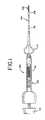
- FIG. 1is an enlarged, partial sectional view of the hydraulic vascular occlusive coil deployment system of the present invention
- FIG. 2is an enlarged partially sectional view showing the distal end of the coil deployment system prior to deployment of the coil;
- FIGS. 3 and 4illustrate the sequential steps in the radial expansion of the distal tip of the coil deployment system as the embolic coil is released.
- FIG. 5illustrates the distal tip of the coil deployment system after release of the embolic coil.
- FIG. 1generally illustrates the vascular occlusive coil deployment system 100 which is comprised of a hydraulic injector or syringe 102 , coupled to the proximal end of a catheter 104 .
- An embolic coil 106includes a proximal headpiece 122 which is disposed within the lumen of the distal end 108 of the catheter. The headpiece 122 is tightly held within the lumen of the distal section 108 of the catheter 104 until the deployment system is activated for release of the coil.
- the syringe 102includes a threaded piston 110 which is controlled by a handle 112 for infusing fluid into the interior of the catheter 104 .
- the catheter 104includes a winged hub 114 which aides in the insertion of the catheter into the vascular system of the body.
- FIG. 2illustrates in more detail the distal end of the catheter 104 .
- the catheter 104includes a proximal section 116 and the distal section 108 .
- the embolic coil 106is tightly wrapped and bonded to the distal portion of a cylindrical headpiece 122 .
- the proximal portion of the headpiece 122is disposed within the distal section 108 of the catheter and is tightly held within the lumen 120 of this distal section 108 prior to release of the headpiece 122 and attached coil 106 .
- FIG. 2illustrates the vascular occlusive coil deployment system prior to activation of the piston of the syringe and prior to release of the coil.
- the embolic coil 106may take various forms and configurations and may even take the form of a randomly wound coil, however, with the helical wound coil as illustrated in FIG. 2, the coil is provided with a headpiece 122 having a proximal portion which is disposed in a lumen 120 which lumen extends throughout the length of the coil 106 .
- the headpiece 122serves to retain the coil 106 and also to prevent the flow of fluid through the lumen of the coil 106 .
- the headpiece 122When the headpiece 122 is placed in fluid-tight engagement with the lumen 120 the headpiece serves to provide a fluid-tight seal at the distal end of the catheter 104 .
- Adjacent turns of the coil 106 at the proximal end 118 of the coilare preferably continuously welded together and are in turn welded to the headpiece 122 to provide a generally unitary structure.
- the diameter of the headpieceis approximately equal to or slightly larger, than the diameter of the lumen of the catheter so that when the headpiece 122 is inserted into the distal section of the catheter, the outside diameter of the attached coil 106 is approximately equal to the outside diameter of the catheter. This construction results in a deployment system having an overall outside diameter approximately equal to that of the catheter.
- the proximal section 116 and the distal section 108 of the catheter 104are formed of materials having different durometers.
- the proximal section 116is preferably formed of Pebax material having a durometer in a range of about 62D to 75D.
- the proximal sectionis sufficiently flexible to transverse the vasculature of the human body, but is sufficiently rigid such that when a fluid pressure of approximately 300 psi is applied to the interior of this section of the catheter there is very little, if any, radial expansion of the walls of this section.
- the distal section 108 of the catheteris preferably formed of polymer material with a relatively low durometer which, exhibits the characteristic that when a fluid pressure of approximately 300 psi is applied to the interior of the catheter the walls of the distal section 108 expand radially, somewhat similar to the action of a balloon inflating, to thereby release the proximal end 118 of the coil 106 .
- the distal section 108is preferably formed from a block copolymer such as Pebax having a durometer of between 25D and 55D with a durometer of 40D being the preferred durometer.
- FIGS. 3 and 4generally illustrate the coil release mechanism in action for the vascular occlusive catheter deployment system. More particularly, as shown in FIG. 3, when a hydraulic pressure is applied to the interior 124 of the catheter 104 the relatively low durometer distal section 108 of the catheter begins to expand radially, much as a balloon expands during the process of inflation. As the distal section 108 continues to expand radially there comes a point as illustrated in FIG. 4 in which the headpiece 122 and attached coil 106 becomes disengaged from the lumen of the distal section 108 and the coil is then released from the catheter and is deployed within the vessel.
- the cathetermay then be withdrawn leaving the coil positioned at the desired site.
- the cathetermay be activated by applying a hydraulic pressure to the interior of the catheter to thereby cause the catheter to release the coil and deposit the coil very accurately at the desired location.
Landscapes
- Health & Medical Sciences (AREA)
- Surgery (AREA)
- Life Sciences & Earth Sciences (AREA)
- Heart & Thoracic Surgery (AREA)
- Molecular Biology (AREA)
- Vascular Medicine (AREA)
- Engineering & Computer Science (AREA)
- Biomedical Technology (AREA)
- Reproductive Health (AREA)
- Medical Informatics (AREA)
- Nuclear Medicine, Radiotherapy & Molecular Imaging (AREA)
- Animal Behavior & Ethology (AREA)
- General Health & Medical Sciences (AREA)
- Public Health (AREA)
- Veterinary Medicine (AREA)
- Surgical Instruments (AREA)
- Media Introduction/Drainage Providing Device (AREA)
Abstract
Description
Claims (14)
Priority Applications (8)
| Application Number | Priority Date | Filing Date | Title |
|---|---|---|---|
| US09/580,684US6379374B1 (en) | 1998-10-22 | 2000-05-30 | Small diameter embolic coil hydraulic deployment system |
| JP2001160580AJP4852201B2 (en) | 2000-05-30 | 2001-05-29 | Hydraulic placement system for small diameter embolic coils |
| EP01304713AEP1159922B1 (en) | 2000-05-30 | 2001-05-29 | Small diameter embolic coil hydraulic deployment system |
| DE60134513TDE60134513D1 (en) | 2000-05-30 | 2001-05-29 | Hydraulic release system for small diameter embolic coil springs |
| AT01304713TATE398968T1 (en) | 2000-05-30 | 2001-05-29 | HYDRAULIC RELEASE SYSTEM FOR SMALL DIAMETER EMBOLIC CIRCULAR SPRINGS |
| CA002349023ACA2349023C (en) | 2000-05-30 | 2001-05-29 | Small diameter embolic coil hydraulic deployment system |
| US10/102,154US6994711B2 (en) | 1998-03-10 | 2002-03-19 | Small diameter embolic coil hydraulic deployment system |
| US11/047,223US7556631B2 (en) | 1998-03-10 | 2005-01-31 | Small diameter embolic coil hydraulic deployment system |
Applications Claiming Priority (2)
| Application Number | Priority Date | Filing Date | Title |
|---|---|---|---|
| US09/177,848US6113622A (en) | 1998-03-10 | 1998-10-22 | Embolic coil hydraulic deployment system |
| US09/580,684US6379374B1 (en) | 1998-10-22 | 2000-05-30 | Small diameter embolic coil hydraulic deployment system |
Related Parent Applications (1)
| Application Number | Title | Priority Date | Filing Date |
|---|---|---|---|
| US09/177,848Continuation-In-PartUS6113622A (en) | 1998-03-10 | 1998-10-22 | Embolic coil hydraulic deployment system |
Related Child Applications (1)
| Application Number | Title | Priority Date | Filing Date |
|---|---|---|---|
| US10/102,154ContinuationUS6994711B2 (en) | 1998-03-10 | 2002-03-19 | Small diameter embolic coil hydraulic deployment system |
Publications (1)
| Publication Number | Publication Date |
|---|---|
| US6379374B1true US6379374B1 (en) | 2002-04-30 |
Family
ID=24322109
Family Applications (3)
| Application Number | Title | Priority Date | Filing Date |
|---|---|---|---|
| US09/580,684Expired - LifetimeUS6379374B1 (en) | 1998-03-10 | 2000-05-30 | Small diameter embolic coil hydraulic deployment system |
| US10/102,154Expired - LifetimeUS6994711B2 (en) | 1998-03-10 | 2002-03-19 | Small diameter embolic coil hydraulic deployment system |
| US11/047,223Expired - Fee RelatedUS7556631B2 (en) | 1998-03-10 | 2005-01-31 | Small diameter embolic coil hydraulic deployment system |
Family Applications After (2)
| Application Number | Title | Priority Date | Filing Date |
|---|---|---|---|
| US10/102,154Expired - LifetimeUS6994711B2 (en) | 1998-03-10 | 2002-03-19 | Small diameter embolic coil hydraulic deployment system |
| US11/047,223Expired - Fee RelatedUS7556631B2 (en) | 1998-03-10 | 2005-01-31 | Small diameter embolic coil hydraulic deployment system |
Country Status (6)
| Country | Link |
|---|---|
| US (3) | US6379374B1 (en) |
| EP (1) | EP1159922B1 (en) |
| JP (1) | JP4852201B2 (en) |
| AT (1) | ATE398968T1 (en) |
| CA (1) | CA2349023C (en) |
| DE (1) | DE60134513D1 (en) |
Cited By (41)
| Publication number | Priority date | Publication date | Assignee | Title |
|---|---|---|---|---|
| US20020151915A1 (en)* | 1998-03-10 | 2002-10-17 | Grant Hieshima | Small diameter embolic coil hydraulic deployment system |
| US6514264B1 (en)* | 2000-06-01 | 2003-02-04 | Cordis Neurovascular, Inc. | Embolic coil hydraulic deployment system with purge mechanism |
| US20030093094A1 (en)* | 2001-11-15 | 2003-05-15 | Roberto Diaz | Small diameter deployment system with improved headpiece |
| US20040059367A1 (en)* | 2002-09-20 | 2004-03-25 | Champ Davis | Reattachable introducer for a medical device deployment system |
| US20040059371A1 (en)* | 2002-09-20 | 2004-03-25 | Healy Stephen R. | Detachable introducer for a medical device deployment system |
| US20040087964A1 (en)* | 2001-01-10 | 2004-05-06 | Roberto Diaz | Embolic coil introducer system |
| US20050004598A1 (en)* | 2003-07-03 | 2005-01-06 | Cook Incorporated | Occluding device and method of occluding fluid flow through a body vessel |
| US20050131454A1 (en)* | 1998-03-10 | 2005-06-16 | Grant Hieshima | Embolic coil hydraulic deployment system |
| US20050149109A1 (en)* | 2003-12-23 | 2005-07-07 | Wallace Michael P. | Expanding filler coil |
| US7763077B2 (en) | 2003-12-24 | 2010-07-27 | Biomerix Corporation | Repair of spinal annular defects and annulo-nucleoplasty regeneration |
| US7766934B2 (en) | 2005-07-12 | 2010-08-03 | Cook Incorporated | Embolic protection device with an integral basket and bag |
| US7771452B2 (en) | 2005-07-12 | 2010-08-10 | Cook Incorporated | Embolic protection device with a filter bag that disengages from a basket |
| US7803395B2 (en) | 2003-05-15 | 2010-09-28 | Biomerix Corporation | Reticulated elastomeric matrices, their manufacture and use in implantable devices |
| US7850708B2 (en) | 2005-06-20 | 2010-12-14 | Cook Incorporated | Embolic protection device having a reticulated body with staggered struts |
| US8109962B2 (en) | 2005-06-20 | 2012-02-07 | Cook Medical Technologies Llc | Retrievable device having a reticulation portion with staggered struts |
| US8152831B2 (en) | 2005-11-17 | 2012-04-10 | Cook Medical Technologies Llc | Foam embolic protection device |
| US8182508B2 (en) | 2005-10-04 | 2012-05-22 | Cook Medical Technologies Llc | Embolic protection device |
| US8187298B2 (en) | 2005-08-04 | 2012-05-29 | Cook Medical Technologies Llc | Embolic protection device having inflatable frame |
| US8216269B2 (en) | 2005-11-02 | 2012-07-10 | Cook Medical Technologies Llc | Embolic protection device having reduced profile |
| US8221446B2 (en) | 2005-03-15 | 2012-07-17 | Cook Medical Technologies | Embolic protection device |
| US8252018B2 (en) | 2007-09-14 | 2012-08-28 | Cook Medical Technologies Llc | Helical embolic protection device |
| US8252017B2 (en) | 2005-10-18 | 2012-08-28 | Cook Medical Technologies Llc | Invertible filter for embolic protection |
| US8328860B2 (en) | 2007-03-13 | 2012-12-11 | Covidien Lp | Implant including a coil and a stretch-resistant member |
| US8377092B2 (en) | 2005-09-16 | 2013-02-19 | Cook Medical Technologies Llc | Embolic protection device |
| US8388644B2 (en) | 2008-12-29 | 2013-03-05 | Cook Medical Technologies Llc | Embolic protection device and method of use |
| US8419748B2 (en) | 2007-09-14 | 2013-04-16 | Cook Medical Technologies Llc | Helical thrombus removal device |
| US8632562B2 (en) | 2005-10-03 | 2014-01-21 | Cook Medical Technologies Llc | Embolic protection device |
| US8777978B2 (en) | 2006-04-17 | 2014-07-15 | Covidien Lp | System and method for mechanically positioning intravascular implants |
| US8777979B2 (en) | 2006-04-17 | 2014-07-15 | Covidien Lp | System and method for mechanically positioning intravascular implants |
| US8795315B2 (en) | 2004-10-06 | 2014-08-05 | Cook Medical Technologies Llc | Emboli capturing device having a coil and method for capturing emboli |
| US8801747B2 (en) | 2007-03-13 | 2014-08-12 | Covidien Lp | Implant, a mandrel, and a method of forming an implant |
| US8945169B2 (en) | 2005-03-15 | 2015-02-03 | Cook Medical Technologies Llc | Embolic protection device |
| US9011480B2 (en) | 2012-01-20 | 2015-04-21 | Covidien Lp | Aneurysm treatment coils |
| US9050095B2 (en) | 2004-09-22 | 2015-06-09 | Covidien Lp | Medical implant |
| US9138307B2 (en) | 2007-09-14 | 2015-09-22 | Cook Medical Technologies Llc | Expandable device for treatment of a stricture in a body vessel |
| US9198665B2 (en) | 2004-09-22 | 2015-12-01 | Covidien Lp | Micro-spiral implantation device |
| US9579104B2 (en) | 2011-11-30 | 2017-02-28 | Covidien Lp | Positioning and detaching implants |
| US9687245B2 (en) | 2012-03-23 | 2017-06-27 | Covidien Lp | Occlusive devices and methods of use |
| US9713475B2 (en) | 2014-04-18 | 2017-07-25 | Covidien Lp | Embolic medical devices |
| US9901434B2 (en) | 2007-02-27 | 2018-02-27 | Cook Medical Technologies Llc | Embolic protection device including a Z-stent waist band |
| US9907639B2 (en) | 2006-09-19 | 2018-03-06 | Cook Medical Technologies Llc | Apparatus and methods for in situ embolic protection |
Families Citing this family (60)
| Publication number | Priority date | Publication date | Assignee | Title |
|---|---|---|---|---|
| US7033374B2 (en)* | 2000-09-26 | 2006-04-25 | Microvention, Inc. | Microcoil vaso-occlusive device with multi-axis secondary configuration |
| US20050043585A1 (en)* | 2003-01-03 | 2005-02-24 | Arindam Datta | Reticulated elastomeric matrices, their manufacture and use in implantable devices |
| US7294123B2 (en)* | 2003-12-17 | 2007-11-13 | Corris Neurovascular, Inc. | Activatable bioactive vascular occlusive device and method of use |
| US20050137568A1 (en)* | 2003-12-17 | 2005-06-23 | Jones Donald K. | Activatable bioactive implantable medical device and method of use |
| US20050216049A1 (en)* | 2004-03-29 | 2005-09-29 | Jones Donald K | Vascular occlusive device with elastomeric bioresorbable coating |
| US7247159B2 (en)* | 2004-04-08 | 2007-07-24 | Cordis Neurovascular, Inc. | Activatable bioactive vascular occlusive device |
| US7416757B2 (en)* | 2004-04-08 | 2008-08-26 | Cordis Neurovascular, Inc. | Method of making active embolic coil |
| US20070190108A1 (en)* | 2004-05-17 | 2007-08-16 | Arindam Datta | High performance reticulated elastomeric matrix preparation, properties, reinforcement, and use in surgical devices, tissue augmentation and/or tissue repair |
| US7918872B2 (en)* | 2004-07-30 | 2011-04-05 | Codman & Shurtleff, Inc. | Embolic device delivery system with retractable partially coiled-fiber release |
| US7451765B2 (en)* | 2004-11-18 | 2008-11-18 | Mark Adler | Intra-bronchial apparatus for aspiration and insufflation of lung regions distal to placement or cross communication and deployment and placement system therefor |
| US20060116714A1 (en)* | 2004-11-26 | 2006-06-01 | Ivan Sepetka | Coupling and release devices and methods for their assembly and use |
| US7819891B2 (en)* | 2005-06-02 | 2010-10-26 | Codman & Shurtleff, Inc. | Stretch resistant embolic coil delivery system with spring release mechanism |
| US7799052B2 (en)* | 2005-06-02 | 2010-09-21 | Codman & Shurtleff, Inc. | Stretch resistant embolic coil delivery system with mechanical release mechanism |
| US7819892B2 (en)* | 2005-06-02 | 2010-10-26 | Codman & Shurtleff, Inc. | Embolic coil delivery system with spring wire release mechanism |
| US7708755B2 (en)* | 2005-06-02 | 2010-05-04 | Codman & Shurtleff Inc. | Stretch resistant embolic coil delivery system with combined mechanical and pressure release mechanism |
| US7708754B2 (en) | 2005-06-02 | 2010-05-04 | Codman & Shurtleff, Pc | Stretch resistant embolic coil delivery system with mechanical release mechanism |
| US7811305B2 (en)* | 2005-06-02 | 2010-10-12 | Codman & Shurtleff, Inc. | Stretch resistant embolic coil delivery system with spring release mechanism |
| US7985238B2 (en)* | 2005-06-02 | 2011-07-26 | Codman & Shurtleff, Inc. | Embolic coil delivery system with spring wire release mechanism |
| US7780695B2 (en)* | 2005-06-30 | 2010-08-24 | Codman & Shurtleff, Inc. | Chemically based vascular occlusion device deployment |
| EP1959873B1 (en) | 2005-12-13 | 2015-05-20 | Codman & Shurtleff, Inc. | Detachment actuator for use with medical device deployment systems |
| US7942894B2 (en)* | 2006-01-31 | 2011-05-17 | Codman & Shurtleff, Inc. | Embolic device delivery system |
| US7670353B2 (en)* | 2006-06-12 | 2010-03-02 | Codman & Shurtleff, Inc. | Modified headpiece for hydraulic coil deployment system |
| US7766935B2 (en) | 2006-06-12 | 2010-08-03 | Codman & Shurtleff, Inc. | Modified headpiece for hydraulic coil deployment system |
| US20070299461A1 (en)* | 2006-06-21 | 2007-12-27 | Boston Scientific Scimed, Inc. | Embolic coils and related components, systems, and methods |
| US8366720B2 (en) | 2006-07-31 | 2013-02-05 | Codman & Shurtleff, Inc. | Interventional medical device system having an elongation retarding portion and method of using the same |
| US8062325B2 (en) | 2006-07-31 | 2011-11-22 | Codman & Shurtleff, Inc. | Implantable medical device detachment system and methods of using the same |
| US20080281350A1 (en)* | 2006-12-13 | 2008-11-13 | Biomerix Corporation | Aneurysm Occlusion Devices |
| US8322365B2 (en) | 2010-08-17 | 2012-12-04 | Codman & Shurtleff, Inc. | Implantable adjustable valve |
| US9149615B2 (en) | 2010-08-17 | 2015-10-06 | DePuy Synthes Products, Inc. | Method and tools for implanted device |
| US8920459B2 (en)* | 2012-03-30 | 2014-12-30 | DePuy Synthes Products, LLC | Embolic coil detachment mechanism with flexible distal member and resistive electrical heating element |
| US9808255B2 (en)* | 2012-03-30 | 2017-11-07 | DePuy Synthes Products, Inc. | Embolic coil detachment mechanism with flexible distal member, resistive electrical heating element and shape memory polymer element |
| US9155540B2 (en)* | 2012-03-30 | 2015-10-13 | DePuy Synthes Products, Inc. | Embolic coil detachment mechanism with heating element and kicker |
| US20140058434A1 (en)* | 2012-08-21 | 2014-02-27 | Donald K. Jones | Releasable device system |
| US8868178B2 (en) | 2012-12-11 | 2014-10-21 | Galvani, Ltd. | Arrhythmia electrotherapy device and method with provisions for mitigating patient discomfort |
| US9987014B2 (en)* | 2014-02-06 | 2018-06-05 | Boston Scientific Scimed, Inc. | Occlusion device |
| US11154302B2 (en) | 2014-03-31 | 2021-10-26 | DePuy Synthes Products, Inc. | Aneurysm occlusion device |
| US11076860B2 (en) | 2014-03-31 | 2021-08-03 | DePuy Synthes Products, Inc. | Aneurysm occlusion device |
| CN110545739A (en) | 2017-02-23 | 2019-12-06 | 德普伊新特斯产品公司 | aneurysm devices and delivery systems |
| US10905430B2 (en) | 2018-01-24 | 2021-02-02 | DePuy Synthes Products, Inc. | Aneurysm device and delivery system |
| US11596412B2 (en) | 2018-05-25 | 2023-03-07 | DePuy Synthes Products, Inc. | Aneurysm device and delivery system |
| US11058430B2 (en)* | 2018-05-25 | 2021-07-13 | DePuy Synthes Products, Inc. | Aneurysm device and delivery system |
| US10939915B2 (en) | 2018-05-31 | 2021-03-09 | DePuy Synthes Products, Inc. | Aneurysm device and delivery system |
| US11051825B2 (en) | 2018-08-08 | 2021-07-06 | DePuy Synthes Products, Inc. | Delivery system for embolic braid |
| US11123077B2 (en) | 2018-09-25 | 2021-09-21 | DePuy Synthes Products, Inc. | Intrasaccular device positioning and deployment system |
| US11076861B2 (en) | 2018-10-12 | 2021-08-03 | DePuy Synthes Products, Inc. | Folded aneurysm treatment device and delivery method |
| US11406392B2 (en) | 2018-12-12 | 2022-08-09 | DePuy Synthes Products, Inc. | Aneurysm occluding device for use with coagulating agents |
| US11272939B2 (en) | 2018-12-18 | 2022-03-15 | DePuy Synthes Products, Inc. | Intrasaccular flow diverter for treating cerebral aneurysms |
| US11134953B2 (en) | 2019-02-06 | 2021-10-05 | DePuy Synthes Products, Inc. | Adhesive cover occluding device for aneurysm treatment |
| US11337706B2 (en) | 2019-03-27 | 2022-05-24 | DePuy Synthes Products, Inc. | Aneurysm treatment device |
| US11672542B2 (en) | 2019-05-21 | 2023-06-13 | DePuy Synthes Products, Inc. | Aneurysm treatment with pushable ball segment |
| US11413046B2 (en) | 2019-05-21 | 2022-08-16 | DePuy Synthes Products, Inc. | Layered braided aneurysm treatment device |
| US10653425B1 (en) | 2019-05-21 | 2020-05-19 | DePuy Synthes Products, Inc. | Layered braided aneurysm treatment device |
| US11497504B2 (en) | 2019-05-21 | 2022-11-15 | DePuy Synthes Products, Inc. | Aneurysm treatment with pushable implanted braid |
| US11602350B2 (en) | 2019-12-05 | 2023-03-14 | DePuy Synthes Products, Inc. | Intrasaccular inverting braid with highly flexible fill material |
| US11278292B2 (en) | 2019-05-21 | 2022-03-22 | DePuy Synthes Products, Inc. | Inverting braided aneurysm treatment system and method |
| US11607226B2 (en) | 2019-05-21 | 2023-03-21 | DePuy Synthes Products, Inc. | Layered braided aneurysm treatment device with corrugations |
| US11439403B2 (en)* | 2019-09-17 | 2022-09-13 | DePuy Synthes Products, Inc. | Embolic coil proximal connecting element and stretch resistant fiber |
| US11457926B2 (en) | 2019-12-18 | 2022-10-04 | DePuy Synthes Products, Inc. | Implant having an intrasaccular section and intravascular section |
| US12127743B2 (en) | 2020-09-23 | 2024-10-29 | DePuy Synthes Products, Inc. | Inverting braided aneurysm implant with dome feature |
| CN114081725B (en)* | 2021-12-09 | 2022-07-19 | 刘章 | Ear canal sliver filling device |
Citations (55)
| Publication number | Priority date | Publication date | Assignee | Title |
|---|---|---|---|---|
| US2853070A (en) | 1955-10-05 | 1958-09-23 | Julliard Maurice | Syringes |
| US3334629A (en) | 1964-11-09 | 1967-08-08 | Bertram D Cohn | Occlusive device for inferior vena cava |
| US3353718A (en) | 1966-05-24 | 1967-11-21 | Fischer & Porter Co | Syringe, column or the like |
| US4512338A (en) | 1983-01-25 | 1985-04-23 | Balko Alexander B | Process for restoring patency to body vessels |
| US4734093A (en) | 1985-11-21 | 1988-03-29 | Sarcem S.A. | Remote controlled catheter having a micro-balloon |
| US4743230A (en) | 1985-09-05 | 1988-05-10 | Advanced Cardiovascular Systems, Inc. | Inflating and deflating device for balloon dilatation catheters |
| US4811737A (en) | 1987-11-16 | 1989-03-14 | Schneider-Shiley (Usa) Inc. | Self-purging balloon catheter |
| US4832692A (en) | 1986-10-14 | 1989-05-23 | Cordis Corporation | Inflation syringe assembly for percutaneous transluminal angioplasty |
| US4906241A (en) | 1987-11-30 | 1990-03-06 | Boston Scientific Corporation | Dilation balloon |
| US4919121A (en) | 1989-02-06 | 1990-04-24 | Schneider (Usa) Inc., A Pfizer Company | Inflation device for angioplasty catheter |
| US4938220A (en) | 1986-08-01 | 1990-07-03 | Advanced Cardiovascular Systems, Inc. | Catheter with split tip marker and method of manufacture |
| US4994071A (en) | 1989-05-22 | 1991-02-19 | Cordis Corporation | Bifurcating stent apparatus and method |
| US4994069A (en) | 1988-11-02 | 1991-02-19 | Target Therapeutics | Vaso-occlusion coil and method |
| US5035705A (en) | 1989-01-13 | 1991-07-30 | Scimed Life Systems, Inc. | Method of purging a balloon catheter |
| US5108407A (en) | 1990-06-08 | 1992-04-28 | Rush-Presbyterian St. Luke's Medical Center | Method and apparatus for placement of an embolic coil |
| US5122136A (en) | 1990-03-13 | 1992-06-16 | The Regents Of The University Of California | Endovascular electrolytically detachable guidewire tip for the electroformation of thrombus in arteries, veins, aneurysms, vascular malformations and arteriovenous fistulas |
| US5135486A (en) | 1990-08-31 | 1992-08-04 | Endosonics Corporation | Self-venting balloon dilitation catheter |
| US5137514A (en) | 1990-11-01 | 1992-08-11 | Accumed Systems, Inc. | Inflation syringe assembly for percutaneous transluminal angioplasty |
| US5167624A (en) | 1990-11-09 | 1992-12-01 | Catheter Research, Inc. | Embolus delivery system and method |
| US5168757A (en) | 1990-05-15 | 1992-12-08 | Ryder International Corporation | Fluid displacement and pressurizing device |
| US5201754A (en) | 1985-05-02 | 1993-04-13 | C. R. Bard, Inc. | Balloon dilatation catheter with varying radiopacity |
| US5217484A (en) | 1991-06-07 | 1993-06-08 | Marks Michael P | Retractable-wire catheter device and method |
| US5234437A (en) | 1991-12-12 | 1993-08-10 | Target Therapeutics, Inc. | Detachable pusher-vasoocclusion coil assembly with threaded coupling |
| US5250071A (en) | 1992-09-22 | 1993-10-05 | Target Therapeutics, Inc. | Detachable embolic coil assembly using interlocking clasps and method of use |
| US5261916A (en) | 1991-12-12 | 1993-11-16 | Target Therapeutics | Detachable pusher-vasoocclusive coil assembly with interlocking ball and keyway coupling |
| US5263964A (en) | 1992-05-06 | 1993-11-23 | Coil Partners Ltd. | Coaxial traction detachment apparatus and method |
| US5304195A (en) | 1991-12-12 | 1994-04-19 | Target Therapeutics, Inc. | Detachable pusher-vasoocclusive coil assembly with interlocking coupling |
| US5312415A (en) | 1992-09-22 | 1994-05-17 | Target Therapeutics, Inc. | Assembly for placement of embolic coils using frictional placement |
| US5334210A (en) | 1993-04-09 | 1994-08-02 | Cook Incorporated | Vascular occlusion assembly |
| US5336183A (en) | 1993-09-28 | 1994-08-09 | Imagyn Medical, Inc. | Inflator |
| US5342304A (en) | 1990-03-16 | 1994-08-30 | Advanced Cardiovascular Systems, Inc. | Inflation device for dilatation catheters |
| US5350397A (en) | 1992-11-13 | 1994-09-27 | Target Therapeutics, Inc. | Axially detachable embolic coil assembly |
| US5382259A (en) | 1992-10-26 | 1995-01-17 | Target Therapeutics, Inc. | Vasoocclusion coil with attached tubular woven or braided fibrous covering |
| US5403292A (en) | 1994-05-18 | 1995-04-04 | Schneider (Usa) Inc. | Thin wall catheter having enhanced torqueability characteristics |
| US5443478A (en) | 1992-09-02 | 1995-08-22 | Board Of Regents, The University Of Texas System | Multi-element intravascular occlusion device |
| US5470317A (en) | 1994-08-02 | 1995-11-28 | Design Standards Corporation | Swivel barrel assembly for inflation syringe |
| WO1996002100A1 (en) | 1994-07-08 | 1996-01-25 | Zenith Electronics Corporation | Trellis coded modulation system for hdtv |
| EP0717969A2 (en) | 1994-12-22 | 1996-06-26 | Target Therapeutics, Inc. | Implant delivery assembly with expandable coupling/decoupling mechanism |
| US5534007A (en) | 1995-05-18 | 1996-07-09 | Scimed Life Systems, Inc. | Stent deployment catheter with collapsible sheath |
| US5551954A (en) | 1991-10-04 | 1996-09-03 | Scimed Life Systems, Inc. | Biodegradable drug delivery vascular stent |
| EP0739607A2 (en) | 1995-04-28 | 1996-10-30 | Target Therapeutics, Inc. | Delivery catheter for electrolytically detachable implant |
| US5578074A (en) | 1994-12-22 | 1996-11-26 | Target Therapeutics, Inc. | Implant delivery method and assembly |
| US5582619A (en) | 1995-06-30 | 1996-12-10 | Target Therapeutics, Inc. | Stretch resistant vaso-occlusive coils |
| US5601600A (en) | 1995-09-08 | 1997-02-11 | Conceptus, Inc. | Endoluminal coil delivery system having a mechanical release mechanism |
| US5609608A (en) | 1995-10-27 | 1997-03-11 | Regents Of The University Of California | Miniature plastic gripper and fabrication method |
| US5647847A (en) | 1994-09-16 | 1997-07-15 | Scimed Life Systems, Inc. | Balloon catheter with improved pressure source |
| US5690667A (en) | 1996-09-26 | 1997-11-25 | Target Therapeutics | Vasoocclusion coil having a polymer tip |
| WO1998002100A1 (en) | 1996-07-16 | 1998-01-22 | Anson Medical Limited | Surgical implants and delivery systems therefor |
| US5728065A (en) | 1996-06-21 | 1998-03-17 | Medtronic, Inc. | Self-venting elastomeric balloon catheter |
| US5772668A (en) | 1992-06-18 | 1998-06-30 | American Biomed, Inc. | Apparatus for placing an endoprosthesis |
| US5817057A (en) | 1996-09-13 | 1998-10-06 | Micro Interventional Systems, Inc. | Fluid propulsion steerable catheter and method |
| US5853418A (en) | 1995-06-30 | 1998-12-29 | Target Therapeutics, Inc. | Stretch resistant vaso-occlusive coils (II) |
| US5925059A (en)* | 1993-04-19 | 1999-07-20 | Target Therapeutics, Inc. | Detachable embolic coil assembly |
| US6068644A (en) | 1998-03-10 | 2000-05-30 | Cordis Corporation | Embolic coil hydraulic deployment system having improved catheter |
| US6117142A (en) | 1998-03-10 | 2000-09-12 | Cordis Corporation | Embolic coil hydraulic deployment system with improved syringe injector |
Family Cites Families (14)
| Publication number | Priority date | Publication date | Assignee | Title |
|---|---|---|---|---|
| US6083220A (en)* | 1990-03-13 | 2000-07-04 | The Regents Of The University Of California | Endovascular electrolytically detachable wire and tip for the formation of thrombus in arteries, veins, aneurysms, vascular malformations and arteriovenous fistulas |
| IL106946A0 (en)* | 1992-09-22 | 1993-12-28 | Target Therapeutics Inc | Detachable embolic coil assembly |
| US5453090A (en) | 1994-03-01 | 1995-09-26 | Cordis Corporation | Method of stent delivery through an elongate softenable sheath |
| KR0137804B1 (en)* | 1995-02-24 | 1998-04-27 | 박효가 | Fibriform zeolite and its manufacturing method |
| DE19547617C1 (en) | 1995-12-20 | 1997-09-18 | Malte Neus | Appliance for inserting and replacing surgical implant |
| US5895391A (en)* | 1996-09-27 | 1999-04-20 | Target Therapeutics, Inc. | Ball lock joint and introducer for vaso-occlusive member |
| US6156061A (en) | 1997-08-29 | 2000-12-05 | Target Therapeutics, Inc. | Fast-detaching electrically insulated implant |
| US5984929A (en)* | 1997-08-29 | 1999-11-16 | Target Therapeutics, Inc. | Fast detaching electronically isolated implant |
| US6379374B1 (en)* | 1998-10-22 | 2002-04-30 | Cordis Neurovascular, Inc. | Small diameter embolic coil hydraulic deployment system |
| US6183491B1 (en)* | 1998-03-10 | 2001-02-06 | Cordis Corporation | Embolic coil deployment system with improved embolic coil |
| US6063100A (en)* | 1998-03-10 | 2000-05-16 | Cordis Corporation | Embolic coil deployment system with improved embolic coil |
| US6113622A (en)* | 1998-03-10 | 2000-09-05 | Cordis Corporation | Embolic coil hydraulic deployment system |
| US6254612B1 (en)* | 1998-10-22 | 2001-07-03 | Cordis Neurovascular, Inc. | Hydraulic stent deployment system |
| US6102932A (en)* | 1998-12-15 | 2000-08-15 | Micrus Corporation | Intravascular device push wire delivery system |
- 2000
- 2000-05-30USUS09/580,684patent/US6379374B1/ennot_activeExpired - Lifetime
- 2001
- 2001-05-29DEDE60134513Tpatent/DE60134513D1/ennot_activeExpired - Lifetime
- 2001-05-29JPJP2001160580Apatent/JP4852201B2/ennot_activeExpired - Lifetime
- 2001-05-29EPEP01304713Apatent/EP1159922B1/ennot_activeExpired - Lifetime
- 2001-05-29ATAT01304713Tpatent/ATE398968T1/ennot_activeIP Right Cessation
- 2001-05-29CACA002349023Apatent/CA2349023C/ennot_activeExpired - Lifetime
- 2002
- 2002-03-19USUS10/102,154patent/US6994711B2/ennot_activeExpired - Lifetime
- 2005
- 2005-01-31USUS11/047,223patent/US7556631B2/ennot_activeExpired - Fee Related
Patent Citations (56)
| Publication number | Priority date | Publication date | Assignee | Title |
|---|---|---|---|---|
| US2853070A (en) | 1955-10-05 | 1958-09-23 | Julliard Maurice | Syringes |
| US3334629A (en) | 1964-11-09 | 1967-08-08 | Bertram D Cohn | Occlusive device for inferior vena cava |
| US3353718A (en) | 1966-05-24 | 1967-11-21 | Fischer & Porter Co | Syringe, column or the like |
| US4512338A (en) | 1983-01-25 | 1985-04-23 | Balko Alexander B | Process for restoring patency to body vessels |
| US5201754A (en) | 1985-05-02 | 1993-04-13 | C. R. Bard, Inc. | Balloon dilatation catheter with varying radiopacity |
| US4743230A (en) | 1985-09-05 | 1988-05-10 | Advanced Cardiovascular Systems, Inc. | Inflating and deflating device for balloon dilatation catheters |
| US4734093A (en) | 1985-11-21 | 1988-03-29 | Sarcem S.A. | Remote controlled catheter having a micro-balloon |
| US4938220A (en) | 1986-08-01 | 1990-07-03 | Advanced Cardiovascular Systems, Inc. | Catheter with split tip marker and method of manufacture |
| US4832692A (en) | 1986-10-14 | 1989-05-23 | Cordis Corporation | Inflation syringe assembly for percutaneous transluminal angioplasty |
| US4811737A (en) | 1987-11-16 | 1989-03-14 | Schneider-Shiley (Usa) Inc. | Self-purging balloon catheter |
| US4906241A (en) | 1987-11-30 | 1990-03-06 | Boston Scientific Corporation | Dilation balloon |
| US4994069A (en) | 1988-11-02 | 1991-02-19 | Target Therapeutics | Vaso-occlusion coil and method |
| US5035705A (en) | 1989-01-13 | 1991-07-30 | Scimed Life Systems, Inc. | Method of purging a balloon catheter |
| US4919121A (en) | 1989-02-06 | 1990-04-24 | Schneider (Usa) Inc., A Pfizer Company | Inflation device for angioplasty catheter |
| US4994071A (en) | 1989-05-22 | 1991-02-19 | Cordis Corporation | Bifurcating stent apparatus and method |
| US5122136A (en) | 1990-03-13 | 1992-06-16 | The Regents Of The University Of California | Endovascular electrolytically detachable guidewire tip for the electroformation of thrombus in arteries, veins, aneurysms, vascular malformations and arteriovenous fistulas |
| US5928226A (en)* | 1990-03-13 | 1999-07-27 | The Regents Of The University Of California | Endovascular electrolytically detachable wire and tip for the formation of thrombus in arteries, veins, aneurysms, vascular malformations and arteriovenous fistulas |
| US5342304A (en) | 1990-03-16 | 1994-08-30 | Advanced Cardiovascular Systems, Inc. | Inflation device for dilatation catheters |
| US5168757A (en) | 1990-05-15 | 1992-12-08 | Ryder International Corporation | Fluid displacement and pressurizing device |
| US5108407A (en) | 1990-06-08 | 1992-04-28 | Rush-Presbyterian St. Luke's Medical Center | Method and apparatus for placement of an embolic coil |
| US5135486A (en) | 1990-08-31 | 1992-08-04 | Endosonics Corporation | Self-venting balloon dilitation catheter |
| US5137514A (en) | 1990-11-01 | 1992-08-11 | Accumed Systems, Inc. | Inflation syringe assembly for percutaneous transluminal angioplasty |
| US5167624A (en) | 1990-11-09 | 1992-12-01 | Catheter Research, Inc. | Embolus delivery system and method |
| US5217484A (en) | 1991-06-07 | 1993-06-08 | Marks Michael P | Retractable-wire catheter device and method |
| US5551954A (en) | 1991-10-04 | 1996-09-03 | Scimed Life Systems, Inc. | Biodegradable drug delivery vascular stent |
| US5261916A (en) | 1991-12-12 | 1993-11-16 | Target Therapeutics | Detachable pusher-vasoocclusive coil assembly with interlocking ball and keyway coupling |
| US5304195A (en) | 1991-12-12 | 1994-04-19 | Target Therapeutics, Inc. | Detachable pusher-vasoocclusive coil assembly with interlocking coupling |
| US5234437A (en) | 1991-12-12 | 1993-08-10 | Target Therapeutics, Inc. | Detachable pusher-vasoocclusion coil assembly with threaded coupling |
| US5263964A (en) | 1992-05-06 | 1993-11-23 | Coil Partners Ltd. | Coaxial traction detachment apparatus and method |
| US5772668A (en) | 1992-06-18 | 1998-06-30 | American Biomed, Inc. | Apparatus for placing an endoprosthesis |
| US5443478A (en) | 1992-09-02 | 1995-08-22 | Board Of Regents, The University Of Texas System | Multi-element intravascular occlusion device |
| US5312415A (en) | 1992-09-22 | 1994-05-17 | Target Therapeutics, Inc. | Assembly for placement of embolic coils using frictional placement |
| US5250071A (en) | 1992-09-22 | 1993-10-05 | Target Therapeutics, Inc. | Detachable embolic coil assembly using interlocking clasps and method of use |
| US5382259A (en) | 1992-10-26 | 1995-01-17 | Target Therapeutics, Inc. | Vasoocclusion coil with attached tubular woven or braided fibrous covering |
| US5350397A (en) | 1992-11-13 | 1994-09-27 | Target Therapeutics, Inc. | Axially detachable embolic coil assembly |
| US5334210A (en) | 1993-04-09 | 1994-08-02 | Cook Incorporated | Vascular occlusion assembly |
| US5925059A (en)* | 1993-04-19 | 1999-07-20 | Target Therapeutics, Inc. | Detachable embolic coil assembly |
| US5336183A (en) | 1993-09-28 | 1994-08-09 | Imagyn Medical, Inc. | Inflator |
| US5403292A (en) | 1994-05-18 | 1995-04-04 | Schneider (Usa) Inc. | Thin wall catheter having enhanced torqueability characteristics |
| WO1996002100A1 (en) | 1994-07-08 | 1996-01-25 | Zenith Electronics Corporation | Trellis coded modulation system for hdtv |
| US5470317A (en) | 1994-08-02 | 1995-11-28 | Design Standards Corporation | Swivel barrel assembly for inflation syringe |
| US5647847A (en) | 1994-09-16 | 1997-07-15 | Scimed Life Systems, Inc. | Balloon catheter with improved pressure source |
| EP0717969A2 (en) | 1994-12-22 | 1996-06-26 | Target Therapeutics, Inc. | Implant delivery assembly with expandable coupling/decoupling mechanism |
| US5578074A (en) | 1994-12-22 | 1996-11-26 | Target Therapeutics, Inc. | Implant delivery method and assembly |
| EP0739607A2 (en) | 1995-04-28 | 1996-10-30 | Target Therapeutics, Inc. | Delivery catheter for electrolytically detachable implant |
| US5534007A (en) | 1995-05-18 | 1996-07-09 | Scimed Life Systems, Inc. | Stent deployment catheter with collapsible sheath |
| US5853418A (en) | 1995-06-30 | 1998-12-29 | Target Therapeutics, Inc. | Stretch resistant vaso-occlusive coils (II) |
| US5582619A (en) | 1995-06-30 | 1996-12-10 | Target Therapeutics, Inc. | Stretch resistant vaso-occlusive coils |
| US5601600A (en) | 1995-09-08 | 1997-02-11 | Conceptus, Inc. | Endoluminal coil delivery system having a mechanical release mechanism |
| US5609608A (en) | 1995-10-27 | 1997-03-11 | Regents Of The University Of California | Miniature plastic gripper and fabrication method |
| US5728065A (en) | 1996-06-21 | 1998-03-17 | Medtronic, Inc. | Self-venting elastomeric balloon catheter |
| WO1998002100A1 (en) | 1996-07-16 | 1998-01-22 | Anson Medical Limited | Surgical implants and delivery systems therefor |
| US5817057A (en) | 1996-09-13 | 1998-10-06 | Micro Interventional Systems, Inc. | Fluid propulsion steerable catheter and method |
| US5690667A (en) | 1996-09-26 | 1997-11-25 | Target Therapeutics | Vasoocclusion coil having a polymer tip |
| US6068644A (en) | 1998-03-10 | 2000-05-30 | Cordis Corporation | Embolic coil hydraulic deployment system having improved catheter |
| US6117142A (en) | 1998-03-10 | 2000-09-12 | Cordis Corporation | Embolic coil hydraulic deployment system with improved syringe injector |
Non-Patent Citations (8)
| Title |
|---|
| Brochure entitled, "Basix25(TM) Inflation Device," by Merit Medical Systems, Inc. |
| Brochure entitled, "Basix25™ Inflation Device," by Merit Medical Systems, Inc. |
| Brochure entitled, "Detachable Coil System," by Cook. |
| Brochure entitled, "Guglielmi Detachable Coils," by Boston Scientific Label of IDC-18 Interlocking Detachable Coil by Target Therapeutics, Inc. |
| Brochure entitled, "MonarchAP(R) Inflation Device," by Merit Medical System, Inc. Label of B. Braun Inflation Device Kit by B. Braun Medical Inc. |
| Brochure entitled, "MonarchAP® Inflation Device," by Merit Medical System, Inc. Label of B. Braun Inflation Device Kit by B. Braun Medical Inc. |
| U.S. Patent application Ser. No. 09/382,967, filed Aug. 25, 1999, entitled "Hydraulic Stent Deployment System". |
| U.S. Patent Application Ser. No. 09/515,944, filed Feb. 29, 2000, entitled, "Embolic Coil Hydraulic Deployment System With Purge Mechanism". |
Cited By (71)
| Publication number | Priority date | Publication date | Assignee | Title |
|---|---|---|---|---|
| US7758588B2 (en) | 1998-03-10 | 2010-07-20 | Codman & Shurtleff, Inc. | Embolic coil hydraulic deployment system |
| US20050131454A1 (en)* | 1998-03-10 | 2005-06-16 | Grant Hieshima | Embolic coil hydraulic deployment system |
| US20020151915A1 (en)* | 1998-03-10 | 2002-10-17 | Grant Hieshima | Small diameter embolic coil hydraulic deployment system |
| US6994711B2 (en) | 1998-03-10 | 2006-02-07 | Cordis Corporation | Small diameter embolic coil hydraulic deployment system |
| US7556631B2 (en) | 1998-03-10 | 2009-07-07 | Cordis Neurovascular, Inc. | Small diameter embolic coil hydraulic deployment system |
| US6958068B2 (en) | 1998-03-10 | 2005-10-25 | Cordis Corporation | Embolic coil hydraulic deployment system |
| US20050131455A1 (en)* | 1998-03-10 | 2005-06-16 | Grant Hieshima | Small diameter embolic coil hydraulic deployment system |
| US6514264B1 (en)* | 2000-06-01 | 2003-02-04 | Cordis Neurovascular, Inc. | Embolic coil hydraulic deployment system with purge mechanism |
| US7018394B2 (en) | 2001-01-10 | 2006-03-28 | Cordis Neurovascular, Inc. | Embolic coil introducer system |
| US20050234505A1 (en)* | 2001-01-10 | 2005-10-20 | Roberto Diaz | Embolic coil introducer system |
| US20040087964A1 (en)* | 2001-01-10 | 2004-05-06 | Roberto Diaz | Embolic coil introducer system |
| US7753931B2 (en) | 2001-01-10 | 2010-07-13 | Codman & Shurtleff, Inc. | Embolic coil introducer system |
| US20080221610A1 (en)* | 2001-11-15 | 2008-09-11 | Roberto Diaz | Small diameter deployment system with improved headpiece |
| US20040236348A1 (en)* | 2001-11-15 | 2004-11-25 | Roberto Diaz | Small diameter deployment system with improved headpiece |
| US20030093094A1 (en)* | 2001-11-15 | 2003-05-15 | Roberto Diaz | Small diameter deployment system with improved headpiece |
| US6811561B2 (en) | 2001-11-15 | 2004-11-02 | Cordis Neurovascular, Inc. | Small diameter deployment system with improved headpiece |
| US8142471B2 (en) | 2001-11-15 | 2012-03-27 | Codman & Shurtleff, Inc. | Small diameter deployment system with improved headpiece |
| US7208003B2 (en)* | 2002-09-20 | 2007-04-24 | Cordis Neurovascular, Inc. | Reattachable introducer for a medical device deployment system |
| US20060212067A1 (en)* | 2002-09-20 | 2006-09-21 | Champ Davis | Reattachable introducer for a medical device deployment system |
| US20040059367A1 (en)* | 2002-09-20 | 2004-03-25 | Champ Davis | Reattachable introducer for a medical device deployment system |
| US8133252B2 (en) | 2002-09-20 | 2012-03-13 | Codman & Shurtleff, Inc. | Reattachable introducer for a medical device deployment system |
| US20040059371A1 (en)* | 2002-09-20 | 2004-03-25 | Healy Stephen R. | Detachable introducer for a medical device deployment system |
| US7819889B2 (en) | 2002-09-20 | 2010-10-26 | Codman & Shurtleff, Inc. | Detachable introducer for a medical device deployment system |
| US8313506B2 (en) | 2002-09-20 | 2012-11-20 | Codman & Shutleff, Inc. | Reattachable introducer for a medical device deployment system |
| US7803395B2 (en) | 2003-05-15 | 2010-09-28 | Biomerix Corporation | Reticulated elastomeric matrices, their manufacture and use in implantable devices |
| US20050004598A1 (en)* | 2003-07-03 | 2005-01-06 | Cook Incorporated | Occluding device and method of occluding fluid flow through a body vessel |
| US10213209B2 (en) | 2003-07-03 | 2019-02-26 | Cook Medical Technologies Llc | Occluding device and method of occluding fluid flow through a body vessel |
| US11006965B2 (en) | 2003-07-03 | 2021-05-18 | Cook Medical Technologies Llc | Occluding device and method of occluding fluid flow through a body vessel |
| US9301764B2 (en) | 2003-07-03 | 2016-04-05 | Cook Medical Technologies Llc | Occluding device and method of occluding fluid flow through a body vessel |
| US20050149109A1 (en)* | 2003-12-23 | 2005-07-07 | Wallace Michael P. | Expanding filler coil |
| US7763077B2 (en) | 2003-12-24 | 2010-07-27 | Biomerix Corporation | Repair of spinal annular defects and annulo-nucleoplasty regeneration |
| US9050095B2 (en) | 2004-09-22 | 2015-06-09 | Covidien Lp | Medical implant |
| US9198665B2 (en) | 2004-09-22 | 2015-12-01 | Covidien Lp | Micro-spiral implantation device |
| US8795315B2 (en) | 2004-10-06 | 2014-08-05 | Cook Medical Technologies Llc | Emboli capturing device having a coil and method for capturing emboli |
| US8221446B2 (en) | 2005-03-15 | 2012-07-17 | Cook Medical Technologies | Embolic protection device |
| US8945169B2 (en) | 2005-03-15 | 2015-02-03 | Cook Medical Technologies Llc | Embolic protection device |
| US8109962B2 (en) | 2005-06-20 | 2012-02-07 | Cook Medical Technologies Llc | Retrievable device having a reticulation portion with staggered struts |
| US7850708B2 (en) | 2005-06-20 | 2010-12-14 | Cook Incorporated | Embolic protection device having a reticulated body with staggered struts |
| US8845677B2 (en) | 2005-06-20 | 2014-09-30 | Cook Medical Technologies Llc | Retrievable device having a reticulation portion with staggered struts |
| US7766934B2 (en) | 2005-07-12 | 2010-08-03 | Cook Incorporated | Embolic protection device with an integral basket and bag |
| US7771452B2 (en) | 2005-07-12 | 2010-08-10 | Cook Incorporated | Embolic protection device with a filter bag that disengages from a basket |
| US7867247B2 (en) | 2005-07-12 | 2011-01-11 | Cook Incorporated | Methods for embolic protection during treatment of a stenotic lesion in a body vessel |
| US8187298B2 (en) | 2005-08-04 | 2012-05-29 | Cook Medical Technologies Llc | Embolic protection device having inflatable frame |
| US8377092B2 (en) | 2005-09-16 | 2013-02-19 | Cook Medical Technologies Llc | Embolic protection device |
| US8632562B2 (en) | 2005-10-03 | 2014-01-21 | Cook Medical Technologies Llc | Embolic protection device |
| US8182508B2 (en) | 2005-10-04 | 2012-05-22 | Cook Medical Technologies Llc | Embolic protection device |
| US8252017B2 (en) | 2005-10-18 | 2012-08-28 | Cook Medical Technologies Llc | Invertible filter for embolic protection |
| US8216269B2 (en) | 2005-11-02 | 2012-07-10 | Cook Medical Technologies Llc | Embolic protection device having reduced profile |
| US8152831B2 (en) | 2005-11-17 | 2012-04-10 | Cook Medical Technologies Llc | Foam embolic protection device |
| US8777978B2 (en) | 2006-04-17 | 2014-07-15 | Covidien Lp | System and method for mechanically positioning intravascular implants |
| US8795321B2 (en) | 2006-04-17 | 2014-08-05 | Covidien Lp | System and method for mechanically positioning intravascular implants |
| US8864790B2 (en) | 2006-04-17 | 2014-10-21 | Covidien Lp | System and method for mechanically positioning intravascular implants |
| US8795320B2 (en) | 2006-04-17 | 2014-08-05 | Covidien Lp | System and method for mechanically positioning intravascular implants |
| US8777979B2 (en) | 2006-04-17 | 2014-07-15 | Covidien Lp | System and method for mechanically positioning intravascular implants |
| US9907639B2 (en) | 2006-09-19 | 2018-03-06 | Cook Medical Technologies Llc | Apparatus and methods for in situ embolic protection |
| US9901434B2 (en) | 2007-02-27 | 2018-02-27 | Cook Medical Technologies Llc | Embolic protection device including a Z-stent waist band |
| US8801747B2 (en) | 2007-03-13 | 2014-08-12 | Covidien Lp | Implant, a mandrel, and a method of forming an implant |
| US9289215B2 (en) | 2007-03-13 | 2016-03-22 | Covidien Lp | Implant including a coil and a stretch-resistant member |
| US8328860B2 (en) | 2007-03-13 | 2012-12-11 | Covidien Lp | Implant including a coil and a stretch-resistant member |
| US8419748B2 (en) | 2007-09-14 | 2013-04-16 | Cook Medical Technologies Llc | Helical thrombus removal device |
| US8252018B2 (en) | 2007-09-14 | 2012-08-28 | Cook Medical Technologies Llc | Helical embolic protection device |
| US9398946B2 (en) | 2007-09-14 | 2016-07-26 | Cook Medical Technologies Llc | Expandable device for treatment of a stricture in a body vessel |
| US9138307B2 (en) | 2007-09-14 | 2015-09-22 | Cook Medical Technologies Llc | Expandable device for treatment of a stricture in a body vessel |
| US8388644B2 (en) | 2008-12-29 | 2013-03-05 | Cook Medical Technologies Llc | Embolic protection device and method of use |
| US8657849B2 (en) | 2008-12-29 | 2014-02-25 | Cook Medical Technologies Llc | Embolic protection device and method of use |
| US9579104B2 (en) | 2011-11-30 | 2017-02-28 | Covidien Lp | Positioning and detaching implants |
| US10335155B2 (en) | 2011-11-30 | 2019-07-02 | Covidien Lp | Positioning and detaching implants |
| US9011480B2 (en) | 2012-01-20 | 2015-04-21 | Covidien Lp | Aneurysm treatment coils |
| US10893868B2 (en) | 2012-01-20 | 2021-01-19 | Covidien Lp | Aneurysm treatment coils |
| US9687245B2 (en) | 2012-03-23 | 2017-06-27 | Covidien Lp | Occlusive devices and methods of use |
| US9713475B2 (en) | 2014-04-18 | 2017-07-25 | Covidien Lp | Embolic medical devices |
Also Published As
| Publication number | Publication date |
|---|---|
| US20050131455A1 (en) | 2005-06-16 |
| EP1159922A2 (en) | 2001-12-05 |
| CA2349023C (en) | 2008-09-23 |
| ATE398968T1 (en) | 2008-07-15 |
| JP4852201B2 (en) | 2012-01-11 |
| EP1159922B1 (en) | 2008-06-25 |
| US20020151915A1 (en) | 2002-10-17 |
| US7556631B2 (en) | 2009-07-07 |
| CA2349023A1 (en) | 2001-11-30 |
| DE60134513D1 (en) | 2008-08-07 |
| US6994711B2 (en) | 2006-02-07 |
| JP2002017736A (en) | 2002-01-22 |
| EP1159922A3 (en) | 2003-07-09 |
Similar Documents
| Publication | Publication Date | Title |
|---|---|---|
| US6379374B1 (en) | Small diameter embolic coil hydraulic deployment system | |
| US7758588B2 (en) | Embolic coil hydraulic deployment system | |
| US6183491B1 (en) | Embolic coil deployment system with improved embolic coil | |
| US6063100A (en) | Embolic coil deployment system with improved embolic coil | |
| US6514264B1 (en) | Embolic coil hydraulic deployment system with purge mechanism | |
| US6179857B1 (en) | Stretch resistant embolic coil with variable stiffness | |
| US6811561B2 (en) | Small diameter deployment system with improved headpiece | |
| US7708755B2 (en) | Stretch resistant embolic coil delivery system with combined mechanical and pressure release mechanism | |
| US7901444B2 (en) | Embolic coil delivery system with mechanical release mechanism | |
| US7371252B2 (en) | Stretch resistant embolic coil delivery system with mechanical release mechanism | |
| US7208003B2 (en) | Reattachable introducer for a medical device deployment system | |
| US20060276827A1 (en) | Stretch resistant embolic coil delivery system with mechanical release mechanism | |
| US20060276833A1 (en) | Stretch resistant embolic coil delivery system with spring assisted release mechanism | |
| US7819889B2 (en) | Detachable introducer for a medical device deployment system | |
| EP0941701B1 (en) | Stretch resistant embolic coil with variable stiffness |
Legal Events
| Date | Code | Title | Description |
|---|---|---|---|
| AS | Assignment | Owner name:CORDIS CORPORATION, FLORIDA Free format text:ASSIGNMENT OF ASSIGNORS INTEREST;ASSIGNOR:LULO, ROBERT;REEL/FRAME:010851/0352 Effective date:20000525 | |
| AS | Assignment | Owner name:CORDIS NEUROVASCULAR, INC., FLORIDA Free format text:ASSIGNMENT OF ASSIGNORS INTEREST;ASSIGNOR:CORIDS CORPORATION;REEL/FRAME:011122/0887 Effective date:20000821 | |
| AS | Assignment | Owner name:CORDIS CORPORATION, FLORIDA Free format text:ASSIGNMENT OF ASSIGNORS INTEREST;ASSIGNOR:HIESHIMA, GRANT;REEL/FRAME:011126/0689 Effective date:20000828 | |
| STCF | Information on status: patent grant | Free format text:PATENTED CASE | |
| FPAY | Fee payment | Year of fee payment:4 | |
| AS | Assignment | Owner name:CODMAN & SHURTLEFF, INC., MASSACHUSETTS Free format text:MERGER;ASSIGNOR:CORDIS NEUROVASCULAR, INC.;REEL/FRAME:023032/0233 Effective date:20081216 Owner name:CODMAN & SHURTLEFF, INC.,MASSACHUSETTS Free format text:MERGER;ASSIGNOR:CORDIS NEUROVASCULAR, INC.;REEL/FRAME:023032/0233 Effective date:20081216 | |
| FPAY | Fee payment | Year of fee payment:8 | |
| FPAY | Fee payment | Year of fee payment:12 |