US6379201B1 - Marine engine cooling system with a check valve to facilitate draining - Google Patents
Marine engine cooling system with a check valve to facilitate drainingDownload PDFInfo
- Publication number
- US6379201B1 US6379201B1US09/716,533US71653300AUS6379201B1US 6379201 B1US6379201 B1US 6379201B1US 71653300 AUS71653300 AUS 71653300AUS 6379201 B1US6379201 B1US 6379201B1
- Authority
- US
- United States
- Prior art keywords
- port
- cavity
- fluid
- cooling system
- water
- Prior art date
- Legal status (The legal status is an assumption and is not a legal conclusion. Google has not performed a legal analysis and makes no representation as to the accuracy of the status listed.)
- Expired - Lifetime
Links
- 238000001816coolingMethods0.000titleclaimsabstractdescription85
- XLYOFNOQVPJJNP-UHFFFAOYSA-NwaterSubstancesOXLYOFNOQVPJJNP-UHFFFAOYSA-N0.000claimsabstractdescription92
- 239000012530fluidSubstances0.000claimsabstractdescription83
- 238000004891communicationMethods0.000claimsdescription35
- 239000002826coolantSubstances0.000claimsdescription17
- 239000000498cooling waterSubstances0.000claimsdescription10
- 230000005484gravityEffects0.000claimsdescription9
- 241000005139Lycium andersoniiSpecies0.000claimsdescription3
- 239000007788liquidSubstances0.000description7
- 239000013535sea waterSubstances0.000description7
- LYCAIKOWRPUZTN-UHFFFAOYSA-NEthylene glycolChemical compoundOCCOLYCAIKOWRPUZTN-UHFFFAOYSA-N0.000description6
- 239000013505freshwaterSubstances0.000description5
- 238000011010flushing procedureMethods0.000description4
- 230000000903blocking effectEffects0.000description3
- WGCNASOHLSPBMP-UHFFFAOYSA-NhydroxyacetaldehydeNatural productsOCC=OWGCNASOHLSPBMP-UHFFFAOYSA-N0.000description3
- 230000009286beneficial effectEffects0.000description2
- 230000000694effectsEffects0.000description2
- 238000007710freezingMethods0.000description2
- 230000008014freezingEffects0.000description2
- 238000005086pumpingMethods0.000description2
- 230000002301combined effectEffects0.000description1
- 238000002485combustion reactionMethods0.000description1
- 230000007423decreaseEffects0.000description1
- 239000007789gasSubstances0.000description1
- 230000003993interactionEffects0.000description1
- 238000005461lubricationMethods0.000description1
- 239000000463materialSubstances0.000description1
- 238000000034methodMethods0.000description1
- 238000007789sealingMethods0.000description1
- 230000009528severe injuryEffects0.000description1
Images


Classifications
- F—MECHANICAL ENGINEERING; LIGHTING; HEATING; WEAPONS; BLASTING
- F01—MACHINES OR ENGINES IN GENERAL; ENGINE PLANTS IN GENERAL; STEAM ENGINES
- F01P—COOLING OF MACHINES OR ENGINES IN GENERAL; COOLING OF INTERNAL-COMBUSTION ENGINES
- F01P3/00—Liquid cooling
- F01P3/20—Cooling circuits not specific to a single part of engine or machine
- F01P3/207—Cooling circuits not specific to a single part of engine or machine liquid-to-liquid heat-exchanging relative to marine vessels
- B—PERFORMING OPERATIONS; TRANSPORTING
- B63—SHIPS OR OTHER WATERBORNE VESSELS; RELATED EQUIPMENT
- B63H—MARINE PROPULSION OR STEERING
- B63H21/00—Use of propulsion power plant or units on vessels
- B63H21/38—Apparatus or methods specially adapted for use on marine vessels, for handling power plant or unit liquids, e.g. lubricants, coolants, fuels or the like
- B63H21/383—Apparatus or methods specially adapted for use on marine vessels, for handling power plant or unit liquids, e.g. lubricants, coolants, fuels or the like for handling cooling-water
- F—MECHANICAL ENGINEERING; LIGHTING; HEATING; WEAPONS; BLASTING
- F02—COMBUSTION ENGINES; HOT-GAS OR COMBUSTION-PRODUCT ENGINE PLANTS
- F02B—INTERNAL-COMBUSTION PISTON ENGINES; COMBUSTION ENGINES IN GENERAL
- F02B61/00—Adaptations of engines for driving vehicles or for driving propellers; Combinations of engines with gearing
- F02B61/04—Adaptations of engines for driving vehicles or for driving propellers; Combinations of engines with gearing for driving propellers
- F—MECHANICAL ENGINEERING; LIGHTING; HEATING; WEAPONS; BLASTING
- F01—MACHINES OR ENGINES IN GENERAL; ENGINE PLANTS IN GENERAL; STEAM ENGINES
- F01P—COOLING OF MACHINES OR ENGINES IN GENERAL; COOLING OF INTERNAL-COMBUSTION ENGINES
- F01P11/00—Component parts, details, or accessories not provided for in, or of interest apart from, groups F01P1/00 - F01P9/00
- F01P11/02—Liquid-coolant filling, overflow, venting, or draining devices
- F01P11/0276—Draining or purging
- F—MECHANICAL ENGINEERING; LIGHTING; HEATING; WEAPONS; BLASTING
- F01—MACHINES OR ENGINES IN GENERAL; ENGINE PLANTS IN GENERAL; STEAM ENGINES
- F01P—COOLING OF MACHINES OR ENGINES IN GENERAL; COOLING OF INTERNAL-COMBUSTION ENGINES
- F01P2050/00—Applications
- F01P2050/02—Marine engines
- F—MECHANICAL ENGINEERING; LIGHTING; HEATING; WEAPONS; BLASTING
- F01—MACHINES OR ENGINES IN GENERAL; ENGINE PLANTS IN GENERAL; STEAM ENGINES
- F01P—COOLING OF MACHINES OR ENGINES IN GENERAL; COOLING OF INTERNAL-COMBUSTION ENGINES
- F01P2050/00—Applications
- F01P2050/02—Marine engines
- F01P2050/06—Marine engines using liquid-to-liquid heat exchangers
- F—MECHANICAL ENGINEERING; LIGHTING; HEATING; WEAPONS; BLASTING
- F01—MACHINES OR ENGINES IN GENERAL; ENGINE PLANTS IN GENERAL; STEAM ENGINES
- F01P—COOLING OF MACHINES OR ENGINES IN GENERAL; COOLING OF INTERNAL-COMBUSTION ENGINES
- F01P2060/00—Cooling circuits using auxiliaries
- F01P2060/16—Outlet manifold
- Y—GENERAL TAGGING OF NEW TECHNOLOGICAL DEVELOPMENTS; GENERAL TAGGING OF CROSS-SECTIONAL TECHNOLOGIES SPANNING OVER SEVERAL SECTIONS OF THE IPC; TECHNICAL SUBJECTS COVERED BY FORMER USPC CROSS-REFERENCE ART COLLECTIONS [XRACs] AND DIGESTS
- Y10—TECHNICAL SUBJECTS COVERED BY FORMER USPC
- Y10T—TECHNICAL SUBJECTS COVERED BY FORMER US CLASSIFICATION
- Y10T137/00—Fluid handling
- Y10T137/2496—Self-proportioning or correlating systems
- Y10T137/2514—Self-proportioning flow systems
- Y10T137/2521—Flow comparison or differential response
Definitions
- the present inventionis generally related to marine engine cooling systems and, more specifically, to a marine engine cooling system that facilitates draining the cooling system when the engine is not operating and provides appropriate engine cooling flow paths during the engine's operation.
- Marine engine cooling systemstypically utilize a pump, sometimes referred to as a seawater pump, to draw water from a body of water in which a marine vessel is operating.
- the water, drawn from a lake or ocean,is then used to lower the temperature of the engine and its associated components. After flowing through passages of the cooling system, the cooling water is returned to the body of water from it was drawn.
- U.S. Pat. No. 5,980,342which issued to Logan et al on Nov. 9, 1999, discloses a flushing system for a marine propulsion engine.
- the flushing systemprovides a pair of check valves that are used in combination with each other.
- One of the check valvesis attached to a hose located between the circulating pump and the thermostat housing of the engine.
- the other check valveis attached to a hose through which fresh water is provided. Both check valves prevent flow of water through them unless they are associated together in locking attachment.
- the check valve attached to the circulating pump hose of the enginedirects a stream of water from the hose toward the circulating pump so that water can then flow through the circulating pump, the engine pump, the heads, the intake manifold, and the exhaust system of the engine to remove seawater residue from the internal passages and surfaces of the engine. It is not required that the engine be operated during the flushing operation.
- U.S. Pat. No. 5,334,063which issued to Inoue et al on Aug. 2, 1994, describes a cooling system for a marine propulsion engine.
- a number of embodiments of cooling systems for marine propulsion unitsare disclosed which have water cooled internal combustion engines in which the cooling jacket of the engine is at least partially positioned below the level of the water in which the water craft is operating.
- the described embodimentsall permit draining of the engine cooling jacket when it is not being run.
- the drain valvealso controls the communication of the coolant from the body of water in which the water is operating with the engine cooling jacket.
- Various types of pumping arrangementsare disclosed for pumping the bilge and automatic valve operation is also disclosed.
- a ballis used to seal either a first or second inlet when the other inlet is used to cause water to flow through the valve.
- the valveallows fresh water to be introduced into a second inlet in order to remove residual and debris from the cooling system of the marine propulsion engine.
- the ballseals the first inlet and causes the fresh water to flow through the engine cooling system.
- waterflows through the first inlet and seals the second inlet by causing the ball to move against a ball seat at the second inlet.
- a stationary sealing devicecan be provided within the second inlet and a bypass channel can be provided to allow water to flow past the ball when the ball is moved against the ball seat at the first inlet. This minimal flow of water is provided to allow lubrication for the seawater pump impeller if the seawater pump is operated during the flushing operation in contradiction to recommended procedure.
- U.S. Pat. No. 6,135,064which issued to Logan et al on Oct. 24, 2000, discloses an improved drain system.
- the engine cooling systemis provided with a manifold that is located below the lowest point of the cooling system of the engine.
- the manifoldis connected to the cooling system of the engine, a water pump, a circulation pump, the exhaust manifolds of the engine, and a drain conduit through which all of the water can be drained from the engine.
- a marine engine cooling system made in accordance with the present inventioncomprises a valve which has first, second, and third ports.
- the valvealso has a cavity within it which is in fluid communication with the first, second, and third ports.
- a ballis disposed within the cavity of the valve. The position of the ball within the cavity is a function of forces on the ball which result from gravity buoyancy or pressure differential and from the movement of fluid through the cavity.
- the marine engine cooling system of the present inventionalso comprises a pump having an outlet connected in fluid communication with the first port of the valve. It further comprises a fluid conducting component connected in fluid communication between the pump and the third port.
- This fluid conducting componentcan be an engine heat exchanger or one or more cooling passages of the engine itself.
- the ballis movable within the cavity to at least partially block fluid flow from the first port to the second port when the fluid pressure at the first port is higher than the fluid pressure at the second port. This movement causes the ball to move up and into contact with a seat associated with the second port. Fluid communication between the second and third ports remains unaffected by movement of the ball within the cavity. A fluid path from the second port to the first port remains open when fluid pressure at the first port is not greater than fluid pressure at the second port.
- the cooling system of the present inventioncan further comprise an exhaust manifold which has a water jacket disposed in fluid communication with the second port in order to receive cooling water from the second port.
- the fluid conducting component of the present inventioncan be a heat exchanger or a cooling passage of the marine engine.
- the valvecan be attached to an exhaust manifold of the engine.
- the marine engine cooling systemcan be a closed system, wherein water pumped from a body of water by the pump flows in thermal communication with a coolant which passes through cooling passages of the marine engine.
- the marine engine cooling systemcan be an open system, wherein water pumped from a body of water by the pump flows through cooling passages of the marine engine in thermal communication with the engine.
- a power steering fluid cooler or other coolerscan be connected in fluid communication with the pump.
- the third port of the valvecan be connected in fluid communication with a conduit that is located between the cavity of the valve and the second port. Flow of fluid between the second and third ports is unaffected by movement of the ball within the cavity of the valve.
- FIGS. 1 and 2show two types of marine engine cooling systems
- FIGS. 3 and 4are simplified illustrations of the present invention in both operating and draining modes
- FIG. 5is a water manifold used in some marine engine cooling systems
- FIGS. 9 and 10show two conditions of an alternative embodiment of the present invention.
- FIGS. 1 and 2show two alternative types of marine engine cooling systems.
- FIG. 1illustrates an exploded schematic representation of a partially closed cooling system for a marine engine.
- the engine cooling systemis closed, but the exhaust manifolds are water cooled with cooling water drawn from the body of water in which the system is operated.
- a pump 10draws water from a body of water represented by dashed box 12 in FIG. 1 .
- the wateris pumped to a junction point identified by reference numeral 14 .
- the junction point 14is connected directly to two valves 20 of the present invention and also to an engine heat exchanger 22 .
- the cooling system shown in FIG. 1is a closed cooling system in which a liquid coolant, such as glycol, is continuously recycled within a closed system.
- That flow of glycol through the closed cooling systemis represented by dashed lines in FIG. 1 .
- the liquid coolantis drawn from the engine heat exchanger 22 by a circulation pump 26 , as represented by dashed line 28 .
- the coolantis pumped into and through the engine block 30 , as represented by dashed line 32 .
- the coolantflows from the engine block 30 to a cross-over manifold 36 which combines the flows of liquid coolant and directs the coolant toward a thermostat 40 , as represented by dashed line 42 .
- the liquid coolant, such as glycolis then directed back to the engine heat exchanger 22 , as represented by dashed line 44 .
- water from the lake or ocean 12flows through the engine heat exchanger 22 and is directed toward the valves 20 of the present invention.
- two valves 20are used because two exhaust manifolds 50 are associated with the engine 30 .
- two fluid paths, 51 and 52are provided between the pump 10 and the valves 20 .
- the flow of water through lines 51 and 52is under the influence of virtually the full pressure provided by the pump 10 .
- the term “seawater”shall mean any water drawn from the ocean or lake in which the marine propulsion system is operated, whether the water is saltwater or freshwater.
- two fluid lines, 61 and 62flow from the engine heat exchanger 22 to the valves 20 .
- seawatercan flow upward and into the water jackets of the exhaust manifolds 50 .
- the watercontinues its flow to the exhaust elbows 70 , through line 72 , and is combined with the exhaust gases flowing from the elbows 70 , as represented by arrows E.
- the flow of water through line 51 to valve 20is at a higher pressure than the flow of water through line 61 to valve 20 .
- the pressure in line 52is greater than line 62 .
- valves 20The reason for this differential magnitude of pressure is that water flowing through lines 61 and 62 pass through the engine heat exchanger 22 prior to flowing to the valves 20 , whereas water through lines 51 and 52 pass directly from pump 10 to valves 20 .
- the structure of the valves 20will be described in greater detail below.
- FIG. 2illustrates an open cooling system of the type that is commonly used in marine propulsion systems.
- the cooling system shown in FIG. 2is also provided with two valves 20 which accomplish functions that are similar to the valves 20 described above in conjunction with FIG. 1 .
- the pump 10draws water from a body of water 12 and provides that water to junction 14 , from which it can flow directly through lines 51 and 52 to the valves 20 of the present invention. From junction 14 , cooling water also flows to a coolant manifold housing 80 similar to that described in significant detail in U.S. Pat. No. 6,135,064.
- the water flowing to manifold housing 80can follow several alternative paths.
- One pathconducts the water directly to the engine block 30 , by paths 81 , 82 , and 83 . This water is caused to flow through cooling passages of the engine 30 to remove heat from the engine.
- the waterflows through the engine, the cylinder heads, and the exhaust manifolds before being returned to the body of water.
- Water from the manifold housing 80can also flow directly to the exhaust elbows 70 , as represented by line 90 .
- the manifold housing 80also has a drain outlet 92 that allows seawater to be drained from the cooling system, as represented by arrow D in FIG. 2 .
- wateris introduced into a flush port 96 . Water can then flow, as represented by arrows 98 , to the cooling passages of the engine 30 and to the valves 20 of the present invention.
- the flush waterfollows the same path as cooling water.
- FIGS. 3 and 4present highly simplified schematic representations of the relevant portions of the cooling system, including the valve 20 which is shown in section view.
- the valve 20has a first port 101 , a second port 102 , and a third port 103 .
- the position of the ball 112 within the cavity 110is a function of the force of gravity on the ball 112 and it is also a function of the movement of fluid through the cavity 110 .
- the specific gravity of the material used to make the ball 112can be greater than or less than the specific gravity of water flowing through the cavity 110 .
- the fluid pressure at the first port 101is greater than the fluid pressure at the second and third ports, 102 and 103 , for the reasons discussed above. Therefore, the ball 112 is moved upward within cavity 110 and against a ball seat to block fluid flow from the first port 101 toward the second port 102 .
- the pressureremains high at the first port 101 , but little or no water flow passes through the cavity 110 because the ball 112 is seated against the ball seat and is blocking that passage.
- Water flowing through line 61after passing through the heat exchanger 22 , is at a lower pressure than the fluid pressure at the first port 101 . Therefore, the pressure above the ball 12 is not sufficient to force it downward and away from its ball seat at the upper portion of cavity 110 .
- FIG. 4shows the components of FIGS. 1 and 3, but with the sea pump 10 not operating.
- the pressure at the first port 101is not greater than the pressure at the second and third ports, 102 and 103 , the ball 112 is free to drop within the cavity 110 and unblock the ball seat at the upper portion of the cavity.
- the flow of water through the cavity 110further urges the ball 112 toward a downward position.
- the lower portion of cavity 110does not comprise a ball seat to allow the ball 112 to block the first port 101 .
- the lower portion of cavity 110is provided with ridges or other type of protrusions to prevent the ball 112 from blocking the first port 101 .
- FIG. 5shows one type of water manifold 120 that can be used in conjunction with an exhaust manifold 50 of the type described above in conjunction with FIGS. 1 and 2.
- the purpose of the water manifold 120is to direct a flow of water into a waterjacket of the exhaust manifold 50 .
- FIG. 6is a section view of the water manifold 120 shown in FIG. 5 .
- the cavity 110is illustrated in FIG. 6, including the ball seat 124 which is a generally conical surface against which the ball can move to block flow upward through the cavity 110 .
- a groove 128is provided to facilitate this combination of components to form the completed valve assembly 20 .
- FIGS. 7 and 8are section views of the member 126 of the water manifold 120 in combination with a valve section 130 .
- the valve section 130can be snapped onto the lower member 126 to define the cavity 110 .
- the valve section 120is pushed into position and a protruding ridge 140 attaches the valve section 120 to the lower member 126 of the water manifold 120 .
- the ball 112is captured within the cavity 120 defined by this assembly.
- the upward flow of water through the first port 101 toward the second port 102causes the ball 112 to move upward against the ball seat 126 and prevent this upward flow.
- the ball 112is free to drop within the cavity 110 , away from the ball seat 124 , and allow water to freely drain downward through the valve from the second port 102 to the first port 101 .
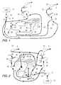
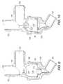
- FIGS. 9 and 10show a slightly different embodiment of the present invention which is intended for use with cooling systems that do not incorporate a water manifold 120 similar to that described above in conjunction with FIG. 5 which has a lower member 126 described above in conjunction with FIGS. 6-8.
- the embodiment shown in FIGS. 9 and 10incorporates a T-shaped insert 150 that is threadable into the lower portion of an exhaust manifold.
- the second port 102is provided with threads 152 for this purpose.
- the valve portion 130can be snapped into position, with the assistance of the O-ring groove 128 and the circumferential protrusion 140 . This assembly forms the cavity 110 which captures the ball 112 within it.
- the ball 112When water is not being pumped by the water pump 10 , to pressurize the fluid at the first port 101 , the ball 112 is free to drop within cavity 110 and move away from the ball seat 124 . This allows an open conduit for water to drain from the second port 102 downward through the cavity 110 , around the ball 112 , and out of the first port 101 .
- the pump 10When the pump 10 is energized and the fluid pressure of the first port 101 rises to a magnitude greater than the fluid pressure at the second and third ports, 102 and 103 , as illustrated in FIG. 10, the ball 112 is moved upward through the cavity to block flow through the cavity 110 in an upward direction from the first port 101 .
- the present inventionprovides a way to easily drain the water from a marine engine. It does not require manual intervention to change the direction of flow through the valve 20 . Instead, the ball 112 moves under the effects of gravity and fluid flow to assume the appropriate positions within the cavity 110 .
- the pressure at the first port 101causes the ball to move upward against the ball seat 124 to block flow through the cavity 110 .
- wateris forced through the heat exchanger 22 , which can be the engine heat exchanger, a power steering fluid heat exchanger, or any cooling passage formed in the engine 30 . This results in a lower pressure at the third port 103 and the ball 112 can remain in its position against the ball seat 124 .
- the seat pump 10is not operating, and the pressure at the first port 101 decreases, the ball 112 is free to fall within the cavity 110 to unblock the passage from the second port 102 to the first port 101 . This allows water to freely drain downward through the cavity 110 in the valve 20 .
- the present inventionwill operate as intended whether or not the ball 112 is less dense or more dense than water. Within reasonable limits of density, the combined effects of gravity on the ball 112 and the forces provided by fluid flow through the cavity 110 will place the ball 112 at the intended positions within the cavity 110 to allow both normal operation of the engine and the draining of the engine when the pump 10 is not operating.
Landscapes
- Engineering & Computer Science (AREA)
- Chemical & Material Sciences (AREA)
- Combustion & Propulsion (AREA)
- Mechanical Engineering (AREA)
- General Engineering & Computer Science (AREA)
- Ocean & Marine Engineering (AREA)
- Exhaust Silencers (AREA)
Abstract
Description
Claims (20)
Priority Applications (1)
| Application Number | Priority Date | Filing Date | Title |
|---|---|---|---|
| US09/716,533US6379201B1 (en) | 2000-11-20 | 2000-11-20 | Marine engine cooling system with a check valve to facilitate draining |
Applications Claiming Priority (1)
| Application Number | Priority Date | Filing Date | Title |
|---|---|---|---|
| US09/716,533US6379201B1 (en) | 2000-11-20 | 2000-11-20 | Marine engine cooling system with a check valve to facilitate draining |
Publications (1)
| Publication Number | Publication Date |
|---|---|
| US6379201B1true US6379201B1 (en) | 2002-04-30 |
Family
ID=24878369
Family Applications (1)
| Application Number | Title | Priority Date | Filing Date |
|---|---|---|---|
| US09/716,533Expired - LifetimeUS6379201B1 (en) | 2000-11-20 | 2000-11-20 | Marine engine cooling system with a check valve to facilitate draining |
Country Status (1)
| Country | Link |
|---|---|
| US (1) | US6379201B1 (en) |
Cited By (19)
| Publication number | Priority date | Publication date | Assignee | Title |
|---|---|---|---|---|
| US6645024B1 (en)* | 2001-11-16 | 2003-11-11 | Joseph Zumpano | Fresh water marine engine flushing assembly and system |
| US6666737B1 (en)* | 2001-09-05 | 2003-12-23 | Honda Giken Kogyo Kabushiki Kaisha | Cooling system for jet propulsion boat |
| US6929520B1 (en) | 2004-06-02 | 2005-08-16 | Brunswick Corporation | Cooling method for a marine propulsion system |
| US6945835B1 (en)* | 2002-10-01 | 2005-09-20 | Glenn Akhavein | Flushing system and process |
| US7094118B1 (en) | 2005-03-23 | 2006-08-22 | Brunswick Corporation | Heat exchanger for a marine propulsion system |
| US20070266965A1 (en)* | 2006-05-19 | 2007-11-22 | Honda Motor Co., Ltd. | Internal combustion engine for small planing boat |
| US7329162B1 (en) | 2006-06-01 | 2008-02-12 | Brunswick Corporation | Cooling system for a marine propulsion device |
| US7497751B1 (en) | 2007-04-27 | 2009-03-03 | Brunswick Corporation | Alternative cooling path system for a marine propulsion device |
| US7585196B1 (en) | 2006-06-01 | 2009-09-08 | Brunswick Corporation | Marine propulsion system with an open cooling system that automatically drains when the marine vessel is taken out of the water |
| US20120097364A1 (en)* | 2010-04-24 | 2012-04-26 | Audi Ag | Valve arrangement for venting a coolant circuit of an internal combustion engine |
| US20130311515A1 (en)* | 2011-01-28 | 2013-11-21 | Max D. Van Gelder | Device for controlling data that is in particular relevant to diabetes |
| US20130333645A1 (en)* | 2012-06-14 | 2013-12-19 | Clemon P. Prevost | Manifold for Use with Water-Cooled Internal Combustion Engines |
| US9254905B1 (en) | 2013-02-20 | 2016-02-09 | Brunswick Corporation | Cooling fluid pump for cooling a marine engine |
| US10524703B2 (en) | 2004-07-13 | 2020-01-07 | Dexcom, Inc. | Transcutaneous analyte sensor |
| US10610137B2 (en) | 2005-03-10 | 2020-04-07 | Dexcom, Inc. | System and methods for processing analyte sensor data for sensor calibration |
| US10813577B2 (en) | 2005-06-21 | 2020-10-27 | Dexcom, Inc. | Analyte sensor |
| US11293335B1 (en) | 2019-12-19 | 2022-04-05 | Brunswick Corporation | Active draining of engine cooling system |
| US20220194543A1 (en)* | 2020-12-23 | 2022-06-23 | Survival Systems International, Inc. | In-davit run kits and methods for lifeboats |
| US11691707B1 (en) | 2019-12-19 | 2023-07-04 | Brunswick Corporation | Cooling system for a power generation system on a marine vessel |
Citations (5)
| Publication number | Priority date | Publication date | Assignee | Title |
|---|---|---|---|---|
| US3550612A (en)* | 1968-07-01 | 1970-12-29 | Leroy James Maxon | Purge valve for cooling fluid conduit systems |
| US5334063A (en) | 1992-04-02 | 1994-08-02 | Sanshin Kogyo Kabushiki Kaisha | Cooling system for marine propulsion engine |
| US5980342A (en) | 1998-10-01 | 1999-11-09 | Brunswick Corporation | Flushing system for a marine propulsion engine |
| US6004175A (en) | 1998-07-08 | 1999-12-21 | Brunswick Corporation | Flush valve |
| US6135064A (en) | 1999-09-21 | 2000-10-24 | Brunswick Corporation | Engine drain system |
- 2000
- 2000-11-20USUS09/716,533patent/US6379201B1/ennot_activeExpired - Lifetime
Patent Citations (5)
| Publication number | Priority date | Publication date | Assignee | Title |
|---|---|---|---|---|
| US3550612A (en)* | 1968-07-01 | 1970-12-29 | Leroy James Maxon | Purge valve for cooling fluid conduit systems |
| US5334063A (en) | 1992-04-02 | 1994-08-02 | Sanshin Kogyo Kabushiki Kaisha | Cooling system for marine propulsion engine |
| US6004175A (en) | 1998-07-08 | 1999-12-21 | Brunswick Corporation | Flush valve |
| US5980342A (en) | 1998-10-01 | 1999-11-09 | Brunswick Corporation | Flushing system for a marine propulsion engine |
| US6135064A (en) | 1999-09-21 | 2000-10-24 | Brunswick Corporation | Engine drain system |
Cited By (57)
| Publication number | Priority date | Publication date | Assignee | Title |
|---|---|---|---|---|
| US6666737B1 (en)* | 2001-09-05 | 2003-12-23 | Honda Giken Kogyo Kabushiki Kaisha | Cooling system for jet propulsion boat |
| US6645024B1 (en)* | 2001-11-16 | 2003-11-11 | Joseph Zumpano | Fresh water marine engine flushing assembly and system |
| US6945835B1 (en)* | 2002-10-01 | 2005-09-20 | Glenn Akhavein | Flushing system and process |
| US6929520B1 (en) | 2004-06-02 | 2005-08-16 | Brunswick Corporation | Cooling method for a marine propulsion system |
| US10980452B2 (en) | 2004-07-13 | 2021-04-20 | Dexcom, Inc. | Analyte sensor |
| US10918313B2 (en) | 2004-07-13 | 2021-02-16 | Dexcom, Inc. | Analyte sensor |
| US11045120B2 (en) | 2004-07-13 | 2021-06-29 | Dexcom, Inc. | Analyte sensor |
| US11026605B1 (en) | 2004-07-13 | 2021-06-08 | Dexcom, Inc. | Analyte sensor |
| US10993642B2 (en) | 2004-07-13 | 2021-05-04 | Dexcom, Inc. | Analyte sensor |
| US10993641B2 (en) | 2004-07-13 | 2021-05-04 | Dexcom, Inc. | Analyte sensor |
| US10709363B2 (en) | 2004-07-13 | 2020-07-14 | Dexcom, Inc. | Analyte sensor |
| US10932700B2 (en) | 2004-07-13 | 2021-03-02 | Dexcom, Inc. | Analyte sensor |
| US11883164B2 (en) | 2004-07-13 | 2024-01-30 | Dexcom, Inc. | System and methods for processing analyte sensor data for sensor calibration |
| US11064917B2 (en) | 2004-07-13 | 2021-07-20 | Dexcom, Inc. | Analyte sensor |
| US10918315B2 (en) | 2004-07-13 | 2021-02-16 | Dexcom, Inc. | Analyte sensor |
| US10918314B2 (en) | 2004-07-13 | 2021-02-16 | Dexcom, Inc. | Analyte sensor |
| US10827956B2 (en) | 2004-07-13 | 2020-11-10 | Dexcom, Inc. | Analyte sensor |
| US10813576B2 (en) | 2004-07-13 | 2020-10-27 | Dexcom, Inc. | Analyte sensor |
| US10524703B2 (en) | 2004-07-13 | 2020-01-07 | Dexcom, Inc. | Transcutaneous analyte sensor |
| US10799159B2 (en) | 2004-07-13 | 2020-10-13 | Dexcom, Inc. | Analyte sensor |
| US10799158B2 (en) | 2004-07-13 | 2020-10-13 | Dexcom, Inc. | Analyte sensor |
| US10722152B2 (en) | 2004-07-13 | 2020-07-28 | Dexcom, Inc. | Analyte sensor |
| US10709362B2 (en) | 2004-07-13 | 2020-07-14 | Dexcom, Inc. | Analyte sensor |
| US10918318B2 (en) | 2005-03-10 | 2021-02-16 | Dexcom, Inc. | System and methods for processing analyte sensor data for sensor calibration |
| US10918317B2 (en) | 2005-03-10 | 2021-02-16 | Dexcom, Inc. | System and methods for processing analyte sensor data for sensor calibration |
| US10617336B2 (en) | 2005-03-10 | 2020-04-14 | Dexcom, Inc. | System and methods for processing analyte sensor data for sensor calibration |
| US10716498B2 (en) | 2005-03-10 | 2020-07-21 | Dexcom, Inc. | System and methods for processing analyte sensor data for sensor calibration |
| US10610136B2 (en) | 2005-03-10 | 2020-04-07 | Dexcom, Inc. | System and methods for processing analyte sensor data for sensor calibration |
| US10743801B2 (en) | 2005-03-10 | 2020-08-18 | Dexcom, Inc. | System and methods for processing analyte sensor data for sensor calibration |
| US10610135B2 (en) | 2005-03-10 | 2020-04-07 | Dexcom, Inc. | System and methods for processing analyte sensor data for sensor calibration |
| US10610137B2 (en) | 2005-03-10 | 2020-04-07 | Dexcom, Inc. | System and methods for processing analyte sensor data for sensor calibration |
| US11000213B2 (en) | 2005-03-10 | 2021-05-11 | Dexcom, Inc. | System and methods for processing analyte sensor data for sensor calibration |
| US10709364B2 (en) | 2005-03-10 | 2020-07-14 | Dexcom, Inc. | System and methods for processing analyte sensor data for sensor calibration |
| US10918316B2 (en) | 2005-03-10 | 2021-02-16 | Dexcom, Inc. | System and methods for processing analyte sensor data for sensor calibration |
| US10856787B2 (en) | 2005-03-10 | 2020-12-08 | Dexcom, Inc. | System and methods for processing analyte sensor data for sensor calibration |
| US10898114B2 (en) | 2005-03-10 | 2021-01-26 | Dexcom, Inc. | System and methods for processing analyte sensor data for sensor calibration |
| US10925524B2 (en) | 2005-03-10 | 2021-02-23 | Dexcom, Inc. | System and methods for processing analyte sensor data for sensor calibration |
| US11051726B2 (en) | 2005-03-10 | 2021-07-06 | Dexcom, Inc. | System and methods for processing analyte sensor data for sensor calibration |
| US7094118B1 (en) | 2005-03-23 | 2006-08-22 | Brunswick Corporation | Heat exchanger for a marine propulsion system |
| US10813577B2 (en) | 2005-06-21 | 2020-10-27 | Dexcom, Inc. | Analyte sensor |
| US20070266965A1 (en)* | 2006-05-19 | 2007-11-22 | Honda Motor Co., Ltd. | Internal combustion engine for small planing boat |
| US7694654B2 (en)* | 2006-05-19 | 2010-04-13 | Honda Motor Co., Ltd. | Internal combustion engine for small planing boat |
| US20080064276A1 (en)* | 2006-06-01 | 2008-03-13 | Brunswick Corporation A Delaware Corporation | Cooling system for a marine propulsion device |
| US7329162B1 (en) | 2006-06-01 | 2008-02-12 | Brunswick Corporation | Cooling system for a marine propulsion device |
| US7585196B1 (en) | 2006-06-01 | 2009-09-08 | Brunswick Corporation | Marine propulsion system with an open cooling system that automatically drains when the marine vessel is taken out of the water |
| US7476135B2 (en) | 2006-06-01 | 2009-01-13 | Brunswick Corporation | Cooling system for a marine propulsion device |
| US7497751B1 (en) | 2007-04-27 | 2009-03-03 | Brunswick Corporation | Alternative cooling path system for a marine propulsion device |
| US8485143B2 (en)* | 2010-04-24 | 2013-07-16 | Audi Ag | Valve arrangement for venting a coolant circuit of an internal combustion engine |
| US20120097364A1 (en)* | 2010-04-24 | 2012-04-26 | Audi Ag | Valve arrangement for venting a coolant circuit of an internal combustion engine |
| US20130311515A1 (en)* | 2011-01-28 | 2013-11-21 | Max D. Van Gelder | Device for controlling data that is in particular relevant to diabetes |
| US20130333645A1 (en)* | 2012-06-14 | 2013-12-19 | Clemon P. Prevost | Manifold for Use with Water-Cooled Internal Combustion Engines |
| US9206731B2 (en)* | 2012-06-14 | 2015-12-08 | Clemon P. Prevost | Manifold for use with water-cooled internal combustion engines |
| US9254905B1 (en) | 2013-02-20 | 2016-02-09 | Brunswick Corporation | Cooling fluid pump for cooling a marine engine |
| US11293335B1 (en) | 2019-12-19 | 2022-04-05 | Brunswick Corporation | Active draining of engine cooling system |
| US11691707B1 (en) | 2019-12-19 | 2023-07-04 | Brunswick Corporation | Cooling system for a power generation system on a marine vessel |
| US20220194543A1 (en)* | 2020-12-23 | 2022-06-23 | Survival Systems International, Inc. | In-davit run kits and methods for lifeboats |
| US11702181B2 (en)* | 2020-12-23 | 2023-07-18 | Survival Systems International, Inc. | In-davit run kits and methods for lifeboats |
Similar Documents
| Publication | Publication Date | Title |
|---|---|---|
| US6379201B1 (en) | Marine engine cooling system with a check valve to facilitate draining | |
| US6821171B1 (en) | Cooling system for a four cycle outboard engine | |
| US6544085B1 (en) | Watercraft having a closed coolant circulating system with a heat exchanger that constitutes an exterior surface of the hull | |
| US7264520B1 (en) | Cooling system for an outboard motor having both open and closed loop portions | |
| US8479691B1 (en) | Method for cooling a four stroke marine engine with multiple path coolant flow through its cylinder head | |
| US7329162B1 (en) | Cooling system for a marine propulsion device | |
| US6135064A (en) | Engine drain system | |
| US4565175A (en) | Engine cooling system | |
| US8402930B1 (en) | Method for cooling a four stroke marine engine with increased segregated heat removal from its exhaust manifold | |
| US20090130928A1 (en) | Cooling system for a turbocharged marine propulsion device | |
| US20170328265A1 (en) | Open Loop Cooling Water System Having Recirculation Pump | |
| US7585196B1 (en) | Marine propulsion system with an open cooling system that automatically drains when the marine vessel is taken out of the water | |
| US6439939B1 (en) | Siphon inhibiting device for a marine cooling system | |
| US6368169B1 (en) | Marine engine cooling system with siphon inhibiting device | |
| US7128027B1 (en) | Cooling system for an outboard motor | |
| US11072408B1 (en) | Marine engines and cooling systems for cooling lubricant in a crankcase of a marine engine | |
| US7699675B1 (en) | Marine exhaust elbow with condensation reducing water circulation system | |
| JP3455546B2 (en) | Multi-engine device with common fresh water cooling system | |
| US8317557B2 (en) | Anti-ingestion system for a marine drive | |
| US6929520B1 (en) | Cooling method for a marine propulsion system | |
| US3125081A (en) | Cooling systems for marine engines | |
| US7455035B2 (en) | Cooling water piping attachment structure for small boat | |
| US6945835B1 (en) | Flushing system and process | |
| KR19990016979A (en) | Marine Engine Cooling System | |
| RU2418177C2 (en) | Device for cooling marine engines of internal combustion |
Legal Events
| Date | Code | Title | Description |
|---|---|---|---|
| AS | Assignment | Owner name:BRUNSWICK CORPORATION, ILLINOIS Free format text:ASSIGNMENT OF ASSIGNORS INTEREST;ASSIGNORS:BIGGS, TIMOTHY M.;JAEGER, MATTHEW W.;LOGAN, ANDREW K.;AND OTHERS;REEL/FRAME:011339/0899;SIGNING DATES FROM 20001115 TO 20001116 | |
| STCF | Information on status: patent grant | Free format text:PATENTED CASE | |
| FPAY | Fee payment | Year of fee payment:4 | |
| AS | Assignment | Owner name:JPMORGAN CHASE BANK, N.A., TEXAS Free format text:SECURITY AGREEMENT;ASSIGNORS:BRUNSWICK CORPORATION;TRITON BOAT COMPANY, L.P.;ATTWOOD CORPORATION;AND OTHERS;REEL/FRAME:022092/0365 Effective date:20081219 Owner name:JPMORGAN CHASE BANK, N.A.,TEXAS Free format text:SECURITY AGREEMENT;ASSIGNORS:BRUNSWICK CORPORATION;TRITON BOAT COMPANY, L.P.;ATTWOOD CORPORATION;AND OTHERS;REEL/FRAME:022092/0365 Effective date:20081219 | |
| AS | Assignment | Owner name:THE BANK OF NEW YORK MELLON TRUST COMPANY, N.A., I Free format text:SECURITY AGREEMENT;ASSIGNORS:BRUNSWICK CORPORATION;ATTWOOD CORPORATION;BOSTON WHALER, INC.;AND OTHERS;REEL/FRAME:023180/0493 Effective date:20090814 Owner name:THE BANK OF NEW YORK MELLON TRUST COMPANY, N.A.,IL Free format text:SECURITY AGREEMENT;ASSIGNORS:BRUNSWICK CORPORATION;ATTWOOD CORPORATION;BOSTON WHALER, INC.;AND OTHERS;REEL/FRAME:023180/0493 Effective date:20090814 | |
| FPAY | Fee payment | Year of fee payment:8 | |
| AS | Assignment | Owner name:LAND 'N' SEA DISTRIBUTING, INC., FLORIDA Free format text:RELEASE BY SECURED PARTY;ASSIGNOR:JPMORGAN CHASE BANK, N.A., AS ADMINISTRATIVE AGENT;REEL/FRAME:026026/0001 Effective date:20110321 Owner name:LUND BOAT COMPANY, MINNESOTA Free format text:RELEASE BY SECURED PARTY;ASSIGNOR:JPMORGAN CHASE BANK, N.A., AS ADMINISTRATIVE AGENT;REEL/FRAME:026026/0001 Effective date:20110321 Owner name:TRITON BOAT COMPANY, L.P., TENNESSEE Free format text:RELEASE BY SECURED PARTY;ASSIGNOR:JPMORGAN CHASE BANK, N.A., AS ADMINISTRATIVE AGENT;REEL/FRAME:026026/0001 Effective date:20110321 Owner name:ATTWOOD CORPORATION, MICHIGAN Free format text:RELEASE BY SECURED PARTY;ASSIGNOR:JPMORGAN CHASE BANK, N.A., AS ADMINISTRATIVE AGENT;REEL/FRAME:026026/0001 Effective date:20110321 Owner name:BRUNSWICK CORPORATION, ILLINOIS Free format text:RELEASE BY SECURED PARTY;ASSIGNOR:JPMORGAN CHASE BANK, N.A., AS ADMINISTRATIVE AGENT;REEL/FRAME:026026/0001 Effective date:20110321 Owner name:BOSTON WHALER, INC., FLORIDA Free format text:RELEASE BY SECURED PARTY;ASSIGNOR:JPMORGAN CHASE BANK, N.A., AS ADMINISTRATIVE AGENT;REEL/FRAME:026026/0001 Effective date:20110321 Owner name:BRUNSWICK BOWLING & BILLIARDS CORPORATION, ILLINOI Free format text:RELEASE BY SECURED PARTY;ASSIGNOR:JPMORGAN CHASE BANK, N.A., AS ADMINISTRATIVE AGENT;REEL/FRAME:026026/0001 Effective date:20110321 Owner name:BRUNSWICK COMMERICAL & GOVERNMENT PRODUCTS, INC., Free format text:RELEASE BY SECURED PARTY;ASSIGNOR:JPMORGAN CHASE BANK, N.A., AS ADMINISTRATIVE AGENT;REEL/FRAME:026026/0001 Effective date:20110321 Owner name:BRUNSWICK FAMILY BOAT CO. INC., WASHINGTON Free format text:RELEASE BY SECURED PARTY;ASSIGNOR:JPMORGAN CHASE BANK, N.A., AS ADMINISTRATIVE AGENT;REEL/FRAME:026026/0001 Effective date:20110321 Owner name:BRUNSWICK LEISURE BOAT COMPANY, LLC, INDIANA Free format text:RELEASE BY SECURED PARTY;ASSIGNOR:JPMORGAN CHASE BANK, N.A., AS ADMINISTRATIVE AGENT;REEL/FRAME:026026/0001 Effective date:20110321 | |
| AS | Assignment | Owner name:JPMORGAN CHASE BANK, N.A., AS ADMINISTRATIVE AGENT Free format text:SECURITY AGREEMENT;ASSIGNORS:BRUNSWICK CORPORATION;ATTWOOD CORPORATION;BOSTON WHALER, INC.;AND OTHERS;REEL/FRAME:026072/0239 Effective date:20110321 | |
| FPAY | Fee payment | Year of fee payment:12 | |
| AS | Assignment | Owner name:BRUNSWICK CORPORATION, ILLINOIS Free format text:RELEASE BY SECURED PARTY;ASSIGNOR:THE BANK OF NEW YORK MELLON;REEL/FRAME:031973/0242 Effective date:20130717 | |
| AS | Assignment | Owner name:LAND 'N' SEA DISTRIBUTING, INC., ILLINOIS Free format text:RELEASE BY SECURED PARTY;ASSIGNOR:JPMORGAN CHASE BANK, N.A.;REEL/FRAME:034794/0300 Effective date:20141226 Owner name:BRUNSWICK LEISURE BOAT COMPANY, LLC, ILLINOIS Free format text:RELEASE BY SECURED PARTY;ASSIGNOR:JPMORGAN CHASE BANK, N.A.;REEL/FRAME:034794/0300 Effective date:20141226 Owner name:BOSTON WHALER, INC., ILLINOIS Free format text:RELEASE BY SECURED PARTY;ASSIGNOR:JPMORGAN CHASE BANK, N.A.;REEL/FRAME:034794/0300 Effective date:20141226 Owner name:BRUNSWICK CORPORATION, ILLINOIS Free format text:RELEASE BY SECURED PARTY;ASSIGNOR:JPMORGAN CHASE BANK, N.A.;REEL/FRAME:034794/0300 Effective date:20141226 Owner name:ATTWOOD CORPORATION, ILLINOIS Free format text:RELEASE BY SECURED PARTY;ASSIGNOR:JPMORGAN CHASE BANK, N.A.;REEL/FRAME:034794/0300 Effective date:20141226 Owner name:BRUNSWICK BOWLING & BILLIARDS CORPORATION, ILLINOI Free format text:RELEASE BY SECURED PARTY;ASSIGNOR:JPMORGAN CHASE BANK, N.A.;REEL/FRAME:034794/0300 Effective date:20141226 Owner name:BRUNSWICK COMMERCIAL & GOVERNMENT PRODUCTS, INC., Free format text:RELEASE BY SECURED PARTY;ASSIGNOR:JPMORGAN CHASE BANK, N.A.;REEL/FRAME:034794/0300 Effective date:20141226 Owner name:BRUNSWICK FAMILY BOAT CO. INC., ILLINOIS Free format text:RELEASE BY SECURED PARTY;ASSIGNOR:JPMORGAN CHASE BANK, N.A.;REEL/FRAME:034794/0300 Effective date:20141226 Owner name:LUND BOAT COMPANY, ILLINOIS Free format text:RELEASE BY SECURED PARTY;ASSIGNOR:JPMORGAN CHASE BANK, N.A.;REEL/FRAME:034794/0300 Effective date:20141226 |