US6378900B1 - Occupant detection system - Google Patents
Occupant detection systemDownload PDFInfo
- Publication number
- US6378900B1 US6378900B1US09/568,596US56859600AUS6378900B1US 6378900 B1US6378900 B1US 6378900B1US 56859600 AUS56859600 AUS 56859600AUS 6378900 B1US6378900 B1US 6378900B1
- Authority
- US
- United States
- Prior art keywords
- occupant
- vehicle
- electric field
- electrode
- seat
- Prior art date
- Legal status (The legal status is an assumption and is not a legal conclusion. Google has not performed a legal analysis and makes no representation as to the accuracy of the status listed.)
- Expired - Lifetime
Links
- 238000001514detection methodMethods0.000titledescription15
- 230000005684electric fieldEffects0.000claimsabstractdescription140
- 239000003990capacitorSubstances0.000claimsdescription19
- 238000005259measurementMethods0.000claimsdescription13
- 238000000034methodMethods0.000claimsdescription8
- 239000006260foamSubstances0.000claimsdescription7
- 230000008878couplingEffects0.000claimsdescription5
- 238000010168coupling processMethods0.000claimsdescription5
- 238000005859coupling reactionMethods0.000claimsdescription5
- 230000001939inductive effectEffects0.000claimsdescription2
- 230000003287optical effectEffects0.000claimsdescription2
- 230000000694effectsEffects0.000abstractdescription6
- 230000008569processEffects0.000description5
- 230000035945sensitivityEffects0.000description5
- 208000027418Wounds and injuryDiseases0.000description4
- 239000004020conductorSubstances0.000description4
- 230000006378damageEffects0.000description4
- 208000014674injuryDiseases0.000description4
- 230000004913activationEffects0.000description3
- 239000007788liquidSubstances0.000description3
- 239000000758substrateSubstances0.000description3
- 230000005540biological transmissionEffects0.000description2
- 230000000903blocking effectEffects0.000description2
- 210000001217buttockAnatomy0.000description2
- 230000001419dependent effectEffects0.000description2
- 238000010586diagramMethods0.000description2
- 238000006073displacement reactionMethods0.000description2
- 210000003414extremityAnatomy0.000description2
- 210000002414legAnatomy0.000description2
- 241000699670Mus sp.Species0.000description1
- 230000004888barrier functionEffects0.000description1
- 230000008901benefitEffects0.000description1
- 230000000052comparative effectEffects0.000description1
- 238000010276constructionMethods0.000description1
- 230000008021depositionEffects0.000description1
- 238000005516engineering processMethods0.000description1
- 238000005530etchingMethods0.000description1
- 239000003999initiatorSubstances0.000description1
- 230000007246mechanismEffects0.000description1
- 230000004048modificationEffects0.000description1
- 238000012986modificationMethods0.000description1
- 230000037361pathwayEffects0.000description1
- 230000004044responseEffects0.000description1
- 230000000284resting effectEffects0.000description1
- 238000000926separation methodMethods0.000description1
- 230000001629suppressionEffects0.000description1
- 238000009736wettingMethods0.000description1
Images


Classifications
- B—PERFORMING OPERATIONS; TRANSPORTING
- B60—VEHICLES IN GENERAL
- B60R—VEHICLES, VEHICLE FITTINGS, OR VEHICLE PARTS, NOT OTHERWISE PROVIDED FOR
- B60R21/00—Arrangements or fittings on vehicles for protecting or preventing injuries to occupants or pedestrians in case of accidents or other traffic risks
- B60R21/01—Electrical circuits for triggering passive safety arrangements, e.g. airbags, safety belt tighteners, in case of vehicle accidents or impending vehicle accidents
- B60R21/015—Electrical circuits for triggering passive safety arrangements, e.g. airbags, safety belt tighteners, in case of vehicle accidents or impending vehicle accidents including means for detecting the presence or position of passengers, passenger seats or child seats, and the related safety parameters therefor, e.g. speed or timing of airbag inflation in relation to occupant position or seat belt use
- B60R21/01512—Passenger detection systems
- B60R21/0153—Passenger detection systems using field detection presence sensors
- B60R21/01534—Passenger detection systems using field detection presence sensors using electromagneticwaves, e.g. infrared
- B—PERFORMING OPERATIONS; TRANSPORTING
- B60—VEHICLES IN GENERAL
- B60N—SEATS SPECIALLY ADAPTED FOR VEHICLES; VEHICLE PASSENGER ACCOMMODATION NOT OTHERWISE PROVIDED FOR
- B60N2/00—Seats specially adapted for vehicles; Arrangement or mounting of seats in vehicles
- B60N2/002—Seats provided with an occupancy detection means mounted therein or thereon
- B60N2/0021—Seats provided with an occupancy detection means mounted therein or thereon characterised by the type of sensor or measurement
- B60N2/0024—Seats provided with an occupancy detection means mounted therein or thereon characterised by the type of sensor or measurement for identifying, categorising or investigation of the occupant or object on the seat
- B60N2/0027—Seats provided with an occupancy detection means mounted therein or thereon characterised by the type of sensor or measurement for identifying, categorising or investigation of the occupant or object on the seat for detecting the position of the occupant or of occupant's body part
- B60N2/0028—Seats provided with an occupancy detection means mounted therein or thereon characterised by the type of sensor or measurement for identifying, categorising or investigation of the occupant or object on the seat for detecting the position of the occupant or of occupant's body part of a body part, e.g. of an arm or a leg
- B—PERFORMING OPERATIONS; TRANSPORTING
- B60—VEHICLES IN GENERAL
- B60N—SEATS SPECIALLY ADAPTED FOR VEHICLES; VEHICLE PASSENGER ACCOMMODATION NOT OTHERWISE PROVIDED FOR
- B60N2/00—Seats specially adapted for vehicles; Arrangement or mounting of seats in vehicles
- B60N2/002—Seats provided with an occupancy detection means mounted therein or thereon
- B60N2/0021—Seats provided with an occupancy detection means mounted therein or thereon characterised by the type of sensor or measurement
- B60N2/0024—Seats provided with an occupancy detection means mounted therein or thereon characterised by the type of sensor or measurement for identifying, categorising or investigation of the occupant or object on the seat
- B60N2/0029—Seats provided with an occupancy detection means mounted therein or thereon characterised by the type of sensor or measurement for identifying, categorising or investigation of the occupant or object on the seat for detecting the motion of the occupant
- B—PERFORMING OPERATIONS; TRANSPORTING
- B60—VEHICLES IN GENERAL
- B60N—SEATS SPECIALLY ADAPTED FOR VEHICLES; VEHICLE PASSENGER ACCOMMODATION NOT OTHERWISE PROVIDED FOR
- B60N2/00—Seats specially adapted for vehicles; Arrangement or mounting of seats in vehicles
- B60N2/24—Seats specially adapted for vehicles; Arrangement or mounting of seats in vehicles for particular purposes or particular vehicles
- B60N2/26—Seats specially adapted for vehicles; Arrangement or mounting of seats in vehicles for particular purposes or particular vehicles for children
- B60N2/28—Seats readily mountable on, and dismountable from, existing seats or other parts of the vehicle
- B60N2/2857—Seats readily mountable on, and dismountable from, existing seats or other parts of the vehicle characterised by the peculiar orientation of the child
- B60N2/286—Seats readily mountable on, and dismountable from, existing seats or other parts of the vehicle characterised by the peculiar orientation of the child forward facing
- B—PERFORMING OPERATIONS; TRANSPORTING
- B60—VEHICLES IN GENERAL
- B60N—SEATS SPECIALLY ADAPTED FOR VEHICLES; VEHICLE PASSENGER ACCOMMODATION NOT OTHERWISE PROVIDED FOR
- B60N2/00—Seats specially adapted for vehicles; Arrangement or mounting of seats in vehicles
- B60N2/24—Seats specially adapted for vehicles; Arrangement or mounting of seats in vehicles for particular purposes or particular vehicles
- B60N2/26—Seats specially adapted for vehicles; Arrangement or mounting of seats in vehicles for particular purposes or particular vehicles for children
- B60N2/28—Seats readily mountable on, and dismountable from, existing seats or other parts of the vehicle
- B60N2/2857—Seats readily mountable on, and dismountable from, existing seats or other parts of the vehicle characterised by the peculiar orientation of the child
- B60N2/2863—Seats readily mountable on, and dismountable from, existing seats or other parts of the vehicle characterised by the peculiar orientation of the child backward facing
- B—PERFORMING OPERATIONS; TRANSPORTING
- B60—VEHICLES IN GENERAL
- B60R—VEHICLES, VEHICLE FITTINGS, OR VEHICLE PARTS, NOT OTHERWISE PROVIDED FOR
- B60R21/00—Arrangements or fittings on vehicles for protecting or preventing injuries to occupants or pedestrians in case of accidents or other traffic risks
- B60R21/01—Electrical circuits for triggering passive safety arrangements, e.g. airbags, safety belt tighteners, in case of vehicle accidents or impending vehicle accidents
- B60R21/015—Electrical circuits for triggering passive safety arrangements, e.g. airbags, safety belt tighteners, in case of vehicle accidents or impending vehicle accidents including means for detecting the presence or position of passengers, passenger seats or child seats, and the related safety parameters therefor, e.g. speed or timing of airbag inflation in relation to occupant position or seat belt use
- B60R21/01512—Passenger detection systems
- B60R21/01516—Passenger detection systems using force or pressure sensing means
- B—PERFORMING OPERATIONS; TRANSPORTING
- B60—VEHICLES IN GENERAL
- B60R—VEHICLES, VEHICLE FITTINGS, OR VEHICLE PARTS, NOT OTHERWISE PROVIDED FOR
- B60R21/00—Arrangements or fittings on vehicles for protecting or preventing injuries to occupants or pedestrians in case of accidents or other traffic risks
- B60R21/01—Electrical circuits for triggering passive safety arrangements, e.g. airbags, safety belt tighteners, in case of vehicle accidents or impending vehicle accidents
- B60R21/015—Electrical circuits for triggering passive safety arrangements, e.g. airbags, safety belt tighteners, in case of vehicle accidents or impending vehicle accidents including means for detecting the presence or position of passengers, passenger seats or child seats, and the related safety parameters therefor, e.g. speed or timing of airbag inflation in relation to occupant position or seat belt use
- B60R21/01512—Passenger detection systems
- B60R21/0153—Passenger detection systems using field detection presence sensors
- B60R21/01532—Passenger detection systems using field detection presence sensors using electric or capacitive field sensors
- B—PERFORMING OPERATIONS; TRANSPORTING
- B60—VEHICLES IN GENERAL
- B60R—VEHICLES, VEHICLE FITTINGS, OR VEHICLE PARTS, NOT OTHERWISE PROVIDED FOR
- B60R21/00—Arrangements or fittings on vehicles for protecting or preventing injuries to occupants or pedestrians in case of accidents or other traffic risks
- B60R21/01—Electrical circuits for triggering passive safety arrangements, e.g. airbags, safety belt tighteners, in case of vehicle accidents or impending vehicle accidents
- B60R21/015—Electrical circuits for triggering passive safety arrangements, e.g. airbags, safety belt tighteners, in case of vehicle accidents or impending vehicle accidents including means for detecting the presence or position of passengers, passenger seats or child seats, and the related safety parameters therefor, e.g. speed or timing of airbag inflation in relation to occupant position or seat belt use
- B60R21/01512—Passenger detection systems
- B60R21/0153—Passenger detection systems using field detection presence sensors
- B60R21/01536—Passenger detection systems using field detection presence sensors using ultrasonic waves
- B—PERFORMING OPERATIONS; TRANSPORTING
- B60—VEHICLES IN GENERAL
- B60R—VEHICLES, VEHICLE FITTINGS, OR VEHICLE PARTS, NOT OTHERWISE PROVIDED FOR
- B60R21/00—Arrangements or fittings on vehicles for protecting or preventing injuries to occupants or pedestrians in case of accidents or other traffic risks
- B60R21/01—Electrical circuits for triggering passive safety arrangements, e.g. airbags, safety belt tighteners, in case of vehicle accidents or impending vehicle accidents
- B60R21/015—Electrical circuits for triggering passive safety arrangements, e.g. airbags, safety belt tighteners, in case of vehicle accidents or impending vehicle accidents including means for detecting the presence or position of passengers, passenger seats or child seats, and the related safety parameters therefor, e.g. speed or timing of airbag inflation in relation to occupant position or seat belt use
- B60R21/01556—Child-seat detection systems
- G—PHYSICS
- G01—MEASURING; TESTING
- G01B—MEASURING LENGTH, THICKNESS OR SIMILAR LINEAR DIMENSIONS; MEASURING ANGLES; MEASURING AREAS; MEASURING IRREGULARITIES OF SURFACES OR CONTOURS
- G01B7/00—Measuring arrangements characterised by the use of electric or magnetic techniques
- G01B7/02—Measuring arrangements characterised by the use of electric or magnetic techniques for measuring length, width or thickness
- G01B7/023—Measuring arrangements characterised by the use of electric or magnetic techniques for measuring length, width or thickness for measuring distance between sensor and object
- G—PHYSICS
- G01—MEASURING; TESTING
- G01V—GEOPHYSICS; GRAVITATIONAL MEASUREMENTS; DETECTING MASSES OR OBJECTS; TAGS
- G01V3/00—Electric or magnetic prospecting or detecting; Measuring magnetic field characteristics of the earth, e.g. declination, deviation
- G01V3/08—Electric or magnetic prospecting or detecting; Measuring magnetic field characteristics of the earth, e.g. declination, deviation operating with magnetic or electric fields produced or modified by objects or geological structures or by detecting devices
- G01V3/088—Electric or magnetic prospecting or detecting; Measuring magnetic field characteristics of the earth, e.g. declination, deviation operating with magnetic or electric fields produced or modified by objects or geological structures or by detecting devices operating with electric fields
- G—PHYSICS
- G08—SIGNALLING
- G08B—SIGNALLING OR CALLING SYSTEMS; ORDER TELEGRAPHS; ALARM SYSTEMS
- G08B13/00—Burglar, theft or intruder alarms
- G08B13/22—Electrical actuation
- G08B13/26—Electrical actuation by proximity of an intruder causing variation in capacitance or inductance of a circuit
- H—ELECTRICITY
- H03—ELECTRONIC CIRCUITRY
- H03K—PULSE TECHNIQUE
- H03K17/00—Electronic switching or gating, i.e. not by contact-making and –breaking
- H03K17/94—Electronic switching or gating, i.e. not by contact-making and –breaking characterised by the way in which the control signals are generated
- H03K17/945—Proximity switches
- H03K17/955—Proximity switches using a capacitive detector
- B—PERFORMING OPERATIONS; TRANSPORTING
- B60—VEHICLES IN GENERAL
- B60N—SEATS SPECIALLY ADAPTED FOR VEHICLES; VEHICLE PASSENGER ACCOMMODATION NOT OTHERWISE PROVIDED FOR
- B60N2210/00—Sensor types, e.g. for passenger detection systems or for controlling seats
- B60N2210/10—Field detection presence sensors
- B60N2210/12—Capacitive; Electric field
- B—PERFORMING OPERATIONS; TRANSPORTING
- B60—VEHICLES IN GENERAL
- B60N—SEATS SPECIALLY ADAPTED FOR VEHICLES; VEHICLE PASSENGER ACCOMMODATION NOT OTHERWISE PROVIDED FOR
- B60N2210/00—Sensor types, e.g. for passenger detection systems or for controlling seats
- B60N2210/10—Field detection presence sensors
- B60N2210/16—Electromagnetic waves
- B60N2210/18—Infrared
- B—PERFORMING OPERATIONS; TRANSPORTING
- B60—VEHICLES IN GENERAL
- B60N—SEATS SPECIALLY ADAPTED FOR VEHICLES; VEHICLE PASSENGER ACCOMMODATION NOT OTHERWISE PROVIDED FOR
- B60N2210/00—Sensor types, e.g. for passenger detection systems or for controlling seats
- B60N2210/10—Field detection presence sensors
- B60N2210/16—Electromagnetic waves
- B60N2210/20—Radar
- B—PERFORMING OPERATIONS; TRANSPORTING
- B60—VEHICLES IN GENERAL
- B60N—SEATS SPECIALLY ADAPTED FOR VEHICLES; VEHICLE PASSENGER ACCOMMODATION NOT OTHERWISE PROVIDED FOR
- B60N2210/00—Sensor types, e.g. for passenger detection systems or for controlling seats
- B60N2210/10—Field detection presence sensors
- B60N2210/16—Electromagnetic waves
- B60N2210/22—Optical; Photoelectric; Lidar [Light Detection and Ranging]
- B—PERFORMING OPERATIONS; TRANSPORTING
- B60—VEHICLES IN GENERAL
- B60N—SEATS SPECIALLY ADAPTED FOR VEHICLES; VEHICLE PASSENGER ACCOMMODATION NOT OTHERWISE PROVIDED FOR
- B60N2210/00—Sensor types, e.g. for passenger detection systems or for controlling seats
- B60N2210/10—Field detection presence sensors
- B60N2210/26—Ultrasonic, e.g. sonar
- B—PERFORMING OPERATIONS; TRANSPORTING
- B60—VEHICLES IN GENERAL
- B60N—SEATS SPECIALLY ADAPTED FOR VEHICLES; VEHICLE PASSENGER ACCOMMODATION NOT OTHERWISE PROVIDED FOR
- B60N2220/00—Computerised treatment of data for controlling of seats
- B60N2220/20—Computerised treatment of data for controlling of seats using a deterministic algorithm
- B—PERFORMING OPERATIONS; TRANSPORTING
- B60—VEHICLES IN GENERAL
- B60R—VEHICLES, VEHICLE FITTINGS, OR VEHICLE PARTS, NOT OTHERWISE PROVIDED FOR
- B60R21/00—Arrangements or fittings on vehicles for protecting or preventing injuries to occupants or pedestrians in case of accidents or other traffic risks
- B60R2021/003—Arrangements or fittings on vehicles for protecting or preventing injuries to occupants or pedestrians in case of accidents or other traffic risks characterised by occupant or pedestian
- B60R2021/0032—Position of passenger
- B60R2021/0034—Position of passenger lying down
- B—PERFORMING OPERATIONS; TRANSPORTING
- B60—VEHICLES IN GENERAL
- B60R—VEHICLES, VEHICLE FITTINGS, OR VEHICLE PARTS, NOT OTHERWISE PROVIDED FOR
- B60R21/00—Arrangements or fittings on vehicles for protecting or preventing injuries to occupants or pedestrians in case of accidents or other traffic risks
- B60R2021/003—Arrangements or fittings on vehicles for protecting or preventing injuries to occupants or pedestrians in case of accidents or other traffic risks characterised by occupant or pedestian
- B60R2021/0032—Position of passenger
- B60R2021/0037—Position of passenger standing
Definitions
- the instant inventiongenerally relates to occupant detection systems and more particularly to occupant detection systems for influencing the deployment of a safety restraint system responsive to a crash and responsive to the occupant.
- FIG. 1illustrates an embodiment of the instant invention
- FIG. 2illustrates the operation of first and second electric field sensors in accordance with the instant invention
- FIG. 3illustrates a child in a typical rear facing infant seat placed on a vehicle seat incorporating an electric field sensor in accordance with the instant invention
- FIG. 4illustrates a cross section of one embodiment of an electric field sensor in accordance with the instant invention
- FIG. 5illustrates a block diagram of an embodiment of the instant invention
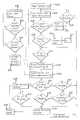
- FIG. 6illustrates a flow chart of an embodiment of the instant invention
- FIG. 7illustrates a sensing circuit in accordance with the instant invention
- FIG. 8illustrates the operation of various elements of the sensing circuit of FIG. 8.
- FIGS. 9 a-jillustrates examples of various seat occupancy scenarios.
- an occupant detection system 10comprises a first electric field sensor 12 for identifying whether there is normally seated, forward facing occupant 14 on the vehicle seat 16 of a vehicle 18 , and a second electric field sensor 20 for determining if a part of the occupant 14 , or another occupant 14 ′, is within a region 22 ′—also known as an at-risk zone 22 —proximate to a restraint actuator 24 of an associated safety restraint system 26 . Occupants within the at-risk zone 22 of the associated safety restraint system 26 may be susceptible to injury by the restraint actuator 24 of a safety restraint system 26 , which in FIG. 1 is illustrated comprising an air bag inflator 28 .
- the first electric field sensor 12comprises at least one first electrode 36 operatively coupled to at least one first applied signal 38 so as to generate an electric field 40 proximate to the at least one first electrode 36 responsive to the first applied signal 38 .
- the first applied signal 38for example comprises either an oscillating or pulsed signal.
- At least one first electrode 36is operatively coupled to a first receiver 42 which outputs at least one first received signal 44 responsive to the electric field 40 at the corresponding first electrode 36 , wherein the first received signal 44 is responsive to at least one electric-field-influencing property—for example dielectric constant, conductivity, size, mass or distance—of an object proximate to the first electric field sensor 12 .
- the first receiver 42measures the capacitance of at least one first electrode 36 with respect to either another first electrode 36 or with respect to a surrounding ground, for example a seat frame 46 of the vehicle seat 16 , connected to circuit ground 48 .
- the at least one first electrode 36may shaped and located so as to be able to distinguish seating conditions for which the restraint actuator 24 should be deployed from seating conditions for which the restraint actuator 24 should not be deployed so as to avoid causing more injury to an occupant 14 than the occupant 14 would otherwise incur without the deployment of the restraint actuator 24 .
- the first electrode 36is shaped and located so that a capacitance of the at least one first electrode 36 with respect to a circuit ground 48 is substantially greater for a seating conditions for which the restraint actuator 24 should be deployed, for example an occupant 14 seated in substantially normal seating position on the vehicle seat 16 or a large body immediately above the seat bottom 30 ; than for a seating condition for which the restraint actuator 24 should not be deployed, for example an empty vehicle seat 16 , an infant, child, or booster seat on the vehicle seat 16 with or without an infant or child seated therein, or an occupant 14 on the vehicle seat 16 in a position that is substantially different from a normal seating position.
- a seating conditions for which the restraint actuator 24 should be deployedfor example an occupant 14 seated in substantially normal seating position on the vehicle seat 16 or a large body immediately above the seat bottom 30 ; than for a seating condition for which the restraint actuator 24 should not be deployed, for example an empty vehicle seat 16 , an infant, child, or booster seat on the vehicle seat 16 with or without an
- the at least one first electrode 36is, for example, substantially the same size as a region to be sensed on the vehicle seat 16 , and sections of the at least one first electrode 36 may be removed to selectively reduce the sensitivity thereof proximate to regions where an infant or child, in an infant, child, or booster seat, is closest to the vehicle seat 16 .
- the second electric field sensor 20comprises at least one second electrode 50 proximate to the restraint actuator 24 of a safety restraint system 26 .
- the second electrode 50is operatively coupled to a second receiver 52 which outputs at least one second received signal 54 responsive to the electric field 40 influencing the second electrode 50 , as generated by the first electric field sensor 12 , responsive to both the proximity of an object to the second electrode 50 , and to the electrostatic coupling of the object to the first electric field sensor 12 .
- the second receiver 52monitors the oscillating or pulsed signal generated by the first electric field sensor 12 . For example, when a pulse is sent out from the first electric field sensor 12 in the seat bottom 30 , the occupant's body effectively becomes part of a “transmission antenna”.
- the second electric field sensor 20identifies if a body part detected in the at-risk zone 22 is well coupled to the first electric field sensor 12 in the seat bottom 30 using a “transmission through the occupant” phenomenon, whereby a variation in voltage applied to the first electric field sensor 12 in the seat bottom 30 is coupled through the occupant 14 seated on the vehicle seat 16 .
- Currents in the occupant's bodyeffectively make the occupant's body an extension of the at least one first electrode 36 of the first electric field sensor 12 . If the occupant's hand is in the at-risk zone 22 , the voltage variation at the first electric field sensor 12 can be sensed by the second receiver 52 of the second electric field sensor 20 , illustrated in the instrument panel.
- the second received signal 54is detected by the second receiver 52 when the occupant 14 is electrostatically well coupled to the seat bottom 30 . Moreover, as illustrated in FIG. 2 b , the second received signal 54 is not detected by the second receiver 52 when the occupant 14 is not electrostatically coupled to the seat bottom 30 .
- the second receiver 52 of the second electric field sensor 20senses a strong signal from the first electric field sensor 12 , if there is strong “transmissive” coupling between the seat bottom 30 and the at least one second electrode 50 of the second electric field sensor 20 .
- thisoccurs when the body part in the at-risk zone 22 is part of the occupant 14 seated directly on the vehicle seat 16 , so that a strong second received signal 54 is indicative of the body part in the at-risk zone 22 belonging to an occupant 14 seated directly on the vehicle seat 16 .
- a second received signal 54 that is not strongis indicative of the body part in the at-risk zone 22 belonging to an occupant 14 ′ not seated directly on the vehicle seat 16 , for example as would result from a “child-on-lap” condition.
- the situations of an adult on the vehicle seat 16 and either a child on the lap of the adult or a child standing between the air bag and the seated adultare generally designated as “child-on-lap” conditions, for which the restraint actuator 24 , for example an air bag inflator 28 , is disabled whenever a child is detected within the at-risk zone 22 the air bag inflator 28 .
- the second electric field sensor 20uses a transmitted signal from the first electric field sensor 12 to identify whether the occupant 14 in the at-risk zone 22 is an occupant 14 on the vehicle seat 16 .
- the occupant 14 detected by the second electric field sensor 20 in the at-risk zone 22could be a “child-on-lap” condition, so the air bag inflator 28 is disabled.
- the first electric field sensor 12generates an electric field 40 with a first applied signal 38 applied to at least one first electrode 36 , and senses the influence of an electric-field-influencing object the electric field 40 with a first receiver 42 operatively connected to at least one first electrode 36 .
- the electric field 40 generated by the first electric field sensor 12is sensed by the second electric field sensor 20 with a second receiver 52 operatively connected to at least one second electrode 50 , at a location proximate to a restraint actuator 24 of a safety restraint system 26 , whereby the strength of the second received signal 54 from the second electric field sensor 20 is dependent upon the proximity of an occupant 14 thereto, and to the degree of coupling by the occupant 14 from the first electric field sensor 12 to the second electric field sensor 20 .
- electric field sensorrefers to a sensor that generates a signal responsive to the influence of that being sensed upon an electric field.
- electric field sensorcomprises at least one electrode to which is applied at least one applied signal and at least one electrode—which could be the same electrode or electrodes to which the applied signal is applied—at which a received signal (or response) is measured.
- the applied signalgenerates an electric field from the at least one electrode to a ground in the environment of the at least one electrode, or to another at least one electrode.
- the applied and received signalscan be associated with the same electrode or electrodes, or with different electrodes.
- the particular electric field associated with a given electrode or set of electrodesis dependent upon the nature and geometry of the electrode or set of electrodes and upon the nature of the surroundings thereto, for example the dielectric properties of the surroundings.
- the received signal or signals of an electric field sensorare responsive to the applied signal or signals and to the nature of the environment influencing the resulting electric field, for example to the presence and location of an object with a permittivity or conductivity different to that of its surroundings.
- One form of electric field sensoris a capacitive sensor, wherein the capacitance of one or more electrodes is measured—from the relationship between received an applied signals—for a given electrode configuration.
- capacitive sensingactually comprises the distinct mechanisms of what the author refers to as “loading mode”, “shunt mode”, and “transmit mode” which correspond to various possible electric current pathways.
- a voltage oscillating at low frequencyis applied to a transmit electrode, and the displacement current induced at a receive electrode is measured with a current amplifier, whereby the displacement current may be modified by the body being sensed.
- the object to be sensedmodifies the capacitance of a transmit electrode relative to ground.
- the transmit electrodeis put in contact with the user's body, which then becomes a transmitter relative to a receiver, either by direct electrical connection or via capacitive coupling.
- the first electric field sensor 12is either what is commonly known as a capacitive sensor, or more generally an electric field sensor operating in any of the above described modes, wherein the first electric field sensor 12 generates an electric field 40 from the first applied signal 38 applied to at least one first electrode 36 and senses objects proximate to the associated at least one first electrode 36 , for example in the seat bottom 30 of a vehicle seat 16 , from the influence of the electric field 40 on the first received signal 44 .
- the at least one first electrode 36 of the first electric field sensor 12 , the first applied signal 38 applied thereto, and the sensitivity of the first receiver 42are all adapted so that the first electric field sensor 12 is substantially non-responsive to objects that are more than 50 mm above the seat bottom 30 , but is responsive to occupants that are normally seated directly on the vehicle seat 16 .
- An electrode of the first 12 and second 20 electric field sensorsmay be constructed in a variety of ways, and the method of construction is not considered limiting.
- an electrodemay be constructed using rigid circuit board or a flexible circuit using known printed circuit board techniques such as etching or deposition of conductive materials applied to a dielectric substrate.
- an electrodemay comprise a discrete conductor, such as a conductive film, sheet or mesh that is distinct from or an integral part of the vehicle seat 16 or components thereof. The assembly of one or more electrodes together with the associated substrate is referred to herein as a sensing pad.
- the occupant detection system 10can be used to sense infants or children in rear facing infant seats, child seats or booster seats, on the basis that the child 300 therein does not have a large surface of its body very near to the seat bottom 30 and the at least one first electrode 36 contained therein.
- the seating contour 304 inside the rear facing infant seat 302is such that the buttocks of the child 300 are closest to the seat bottom 30 of the vehicle seat 16 .
- rear facing infant seats 302are generally made of plastic, the seats themselves are not sensed directly by the first electric field sensor 12 . Even for a rear facing infant seat 302 for which the gap 306 between the child 300 and the seat bottom 30 of the vehicle seat 16 is relatively small, the inside seating contour 304 still creates a significant gap between the at least one first electrode 36 and all parts of the child 300 except the buttocks. Since only a small portion of the surface of the child 300 is near to the at least one first electrode 36 , the associated capacitance thereof is relatively low, and more particularly, less than a threshold capacitance, C norm for detecting a normally seated occupant 14 .
- C normthreshold capacitance
- the first electric field sensor 12may be adapted to reduce the effect that liquids proximate to a first electrode 36 can have on the capacitance thereof with respect to a circuit ground 48 , or with respect to another first electrode 36 .
- liquids spilled on and absorbed by the foam cushion 34can increase the capacitance of the first electrode 36 with respect to the circuit ground 48 .
- the first electric field sensor 12can be adapted to reduce the effect of a wetting of the foam cushion 34 by incorporating a third electrode 400 , known as a driven shield 400 ′, and/or a fourth electrode 402 , known as a ground plane 402 ′, under the at least one first electrode 36 , known as a sensing electrode 36 ′, wherein the first 36 , third 400 and fourth 402 electrodes are insulated from one another, for example by at least one dielectric substrate.
- the first 36 , third 400 and fourth 402 electrodesmay be integrated so as to form a single capacitive sensing pad 404 ′.
- the driven shield 400 ′is a second conductor under the conductor of the sensing electrode 36 ′ that is driven at the same potential as the sensing electrode 36 ′, resulting in a cancellation of the electric field between the sensing electrode 36 ′ and the driven shield 400 ′.
- the driven shield 400 ′eliminates the sensing capability of the capacitive sensing pad 404 ′ on the side of the sensing electrode 36 ′ where the driven shield 400 ′ is located.
- the capacitive sensing pad 404 ′is further improved with a ground plane 402 ′ under the driven shield 400 ′ so that the circuit driving the driven shield 400 ′ drives a consistent load.
- the first electric field sensor 12further comprises at least one third electrode 400 and at least one fourth electrode 402 , wherein the at least one third electrode 400 is located between the at least one first electrode 36 and the at least one fourth electrode 402 , and the at least one third electrode 400 is operatively coupled to a second applied signal 406 .
- the at least one third electrode 400is substantially the same size as the at least one first electrode 36 ; the second applied signal 406 is substantially the same as the first applied signal 38 ; the at least one fourth electrode 402 is located between the at least one first electrode 36 and a foam cushion 34 of the vehicle seat 16 ; the at least one fourth electrode 402 is substantially the same size as the at least one first electrode 36 ; and the at least one fourth electrode 402 is operatively connected to a circuit ground 48 , or to a third applied signal 408 , wherein the third applied signal 408 is a circuit ground 48 potential.
- the driven shield 400 ′ and/or ground plane 402 ′are for example near to or slightly larger than the sensing electrode 36 ′, and are provided to minimize the effects of liquid in the foam cushion 34 below the driven shield 400 ′ and/or ground plane 402 ′ on the capacitance of the sensing electrode 36 ′, rather than to extend the range and sensitivity of the electric field sensor.
- the driven shield 400 ′ and the sensing electrode 36 ′essentially covers the entire area to be sensed on the vehicle seat 16 .
- a plurality of first electrodes 36are distributed sparsely across the vehicle seat 16 , thereby covering a smaller area than the entire area to be sensed on the vehicle seat 16 .
- Each first electrode 36can be embodied in a variety of sizes and shapes, and for a plurality of first electrodes 36 , the arrangement thereof can be embodied in a variety of patterns.
- the at least one first electrode 36comprises a plurality of first electrodes 36 operatively coupled to the first receiver 42 so that different signals from different first electrodes 36 provide information associated with the distribution of an object on the vehicle seat 16 , for example the seating location of an occupant 14 or the size of an occupant 14 .
- the first 12 and second 20 electric field sensorsare operatively connected to a controller 56 , which is operatively coupled to the restraint actuator 24 of a safety restraint system 26 .
- the controller 56discriminates the type and location of an object or occupant 14 located on the vehicle seat 16 , or generally between the vehicle seat 16 and the safety restraint system 26 , and controls the actuation of a safety restraint system 26 responsive thereto in the event of a crash.
- the controller 56distinguishes, from the second received signal 54 —for example from the magnitude thereof—a body part of an occupant 14 seated on the vehicle seat 16 from a body part of an occupant 14 not seated directly on the vehicle 18 , and controls the actuation of a safety restraint system 26 responsive thereto.
- the controller 56disables the safety restraint system 26 if a body part is detected from an occupant 14 not seated directly on the vehicle seat 16 .
- the magnitude of the second received signal 54representing a current transmitted from the first electric field sensor 12 to at least one second electrode 50 or a capacitance of at least one second electrode 50 , is less than a first threshold, then the safety restraint system 26 is disabled.
- the first thresholdcorresponds to the worst case “child-on-lap” condition, or stated another way, the highest capacitance or transmitted current that can be expected from a child proximate to the restraint system.
- the controller 56enables the safety restraint system 26 if the first electric field sensor 12 senses an occupant 14 seated on the vehicle seat 16 and the magnitude of the second received signal 54 is greater than a second threshold, indicating that the body part within the at-risk zone 22 belongs to an occupant 14 seated on the vehicle seat 16 .
- the second received signal 54remains greater than a second threshold for a period of time greater than a third threshold, for example as a result of an occupant 14 in the seat with their feet or legs placed proximate to the safety restraint system 26 , then the safety restraint system 26 is disabled.
- an occupant 14 seated on the seat bottom 30 of a vehicle seat 16sufficiently increases the capacitance of the first electric field sensor 12 so as to indicate to the controller 56 from the first receiver 42 that an occupant 14 is seated against the vehicle seat 16 .
- the second electric field sensor 20determines if a portion of the occupant 14 is located within the at-risk zone 22 of the air bag inflator 28 .
- the signals from the first 12 and second 20 electric field sensorsare operatively coupled to a controller 56 which operates in accordance with known analog, digital, or microprocessor circuitry and software.
- a crash sensor 58is also operatively coupled to the controller 56 .
- the controller 56Responsive to a crash detected by the crash sensor 58 , if an occupant 14 is seated on the seat 3 and is not located within the at-risk zone 22 of the air bag inflator 28 , the controller 56 generates a signal 60 which is operatively coupled to one or more initiators 62 of one or more gas generators 64 mounted in an air bag inflator 28 , thereby controlling the actuation of the air bag inflator 28 so as to inflate the air bag 66 as necessary to protect the occupant 14 from injury which might otherwise be caused by the crash.
- the electrical power necessary to carry out these operationsis provided by a source of power 68 , for example the vehicle battery.
- a range/proximity sensor 70mountable within the seat back 72 of a vehicle seat 16 , wherein the range/proximity sensor 70 when mounted in the seat back 72 of the vehicle seat 16 is for example responsive to a torso of an occupant 14 proximate to the seat back 72 , and provides a measure of distance from the seat back 72 to the torso of the occupant 14 .
- the range/proximity sensor 70operates in accordance with any sensing technology that can provide a measure of the proximity or distance of an occupant 14 to the seat back 72 , for example, including but not limited to a third electric field sensor 74 comprising at least one fifth electrode 76 , a capacitive sensor, a radar sensor, an optical range sensor, an active infrared sensor, a passive infrared sensor, a vision sensor, an ultrasonic range sensor, and an inductive sensor.
- a third electric field sensor 74comprising at least one fifth electrode 76 , a capacitive sensor, a radar sensor, an optical range sensor, an active infrared sensor, a passive infrared sensor, a vision sensor, an ultrasonic range sensor, and an inductive sensor.
- the range/proximity sensor 70is operatively connected to the controller 56 , which discriminates the type of object on the vehicle seat 16 from the at least one first received signal 44 , alone or in combination with the at least one second received signal 54 , and controls the actuation of a safety restraint system 26 responsive thereto, whereby if the second electric field sensor 20 detects an object within an at-risk zone 22 proximate to the safety restraint system 26 then the controller 56 controls the actuation of a safety restraint system 26 responsive to the range/proximity sensor 70 .
- the range/proximity sensor 70for example a a third electric field sensor 74 comprising at least one fifth electrode 76 , is adapted to be responsive to objects within about 50 mm of the seat back 72 within a region from about 250 mm to 500 mm from the seat bottom 30 of the vehicle seat 16 .
- both the first 12 and third electric field sensor 74can share a common electronics module 78 that contains respective first 42 and third 80 receivers that are operatively connected to the respective at least one first electrode 36 and at least one fifth electrode 76 .
- the first 42 and third 80 receiverscan be located proximate to the associated first and fifth 76 electrodes.
- the first applied signal 38 of the first electric field sensor 12is generated by an associated first signal generator 82 , and can also be operatively coupled to at least one fifth electrode 76 of the third electric field sensor 74 .
- a second applied signal 406 from a second signal generator 84can be operatively connected to at least one fifth electrode 76 of the third electric field sensor 74 .
- the third electric field sensor 74can be operated in the “transmit mode” relative to the first electric field sensor 12 , as is the second electric field sensor 20 , wherein the first electric field sensor 12 from at least one first electrode 36 of the first electric field sensor 12 is detected by the third receiver from the at least one fifth electrode 76 of the third electric field sensor 74 .
- the first signal generator 82 or the first 82 and second 84 signal generatorscan also be located in the common electronics module 78 , or located proximate to the associated first 36 and fifth 76 electrodes.
- the range/proximity sensor 70 in the seat back 72 of the vehicle seat 16enables the controller 56 to respond to the movement of the occupant 14 after the crash has begun.
- the range/proximity sensor 70 in the seat back 72can determine if the occupant 14 has moved away from the seat back 72 soon after the crash begins, so as to possibly disable the air bag inflator 28 if the occupant's limbs are in the at-risk zone 22 .
- the at-risk zone 22there is usually a gap of at least 20 centimeters between the at-risk zone 22 and the occupant's head or torso when the occupant 14 is seated against the seat back 72 . Accordingly, whenever an occupant 14 is sensed near to the seat back 72 , it is relatively unlikely for that occupant's head or torso to be within the at-risk zone 22 for at least 50 milliseconds, so that the air bag inflator 28 can safely remain enabled until 50 milliseconds after the occupant 14 moves forward of the seat back 72 .
- a first electric field sensor 12senses if an occupant 14 is seated on the vehicle seat 16 and outputs a first signal 500 representative thereof to the controller 56 , wherein the associated identification process can be performed either by the first electric field sensor 12 or by the controller 56 .
- a second electric field sensor 20senses whether an object is located within the at-risk zone 22 of the safety restraint system 26 , senses the degree to which that object is electrostatically coupled to the vehicle seat 16 , so as to for example distinguish a part of a normally seated occupant 14 from a “child-on-lap” condition, and outputs a second signal 502 representative thereof to a controller 56 , wherein the associated identification process can be performed either by the second electric field sensor 20 or by the controller 56 .
- the range/proximity sensor 70 in the seat back 72senses the distance of the occupant 14 from seat back 72 and outputs a third signal 504 representative thereof to the controller 56 , wherein the associated identification process can be performed either by the range/proximity sensor 70 or by the controller 56 .
- the controller 56determines from respective first 500 , second 502 , and third 504 signals whether or not to disable the safety restraint system 26 , or whether or not to activate the safety restraint system 26 responsive to a crash sensed by a crash sensor 58 , wherein the crash sensor 58 may be either distinct from or incorporated in the controller 56 .
- step ( 602 )a presence flag is reset, wherein the presence flag indicates the presence of an occupant 14 on the seat.
- step ( 604 )a measurement is made by the first electric field sensor 12 so as to detect the presence of an occupant 14 on the seat.
- step ( 606 )If in step ( 606 ) an occupant 14 is detected as being seated directly on the seat, for example as would be the case for a normally seated occupant 14 , then in step ( 608 ) if the presence flag is not set, then in step ( 610 ) the presence flag is set and in step ( 612 ) the first time of a continuous interval of presence is saved as t 0 . Otherwise, in step ( 614 ) the presence flag is reset, indicating that an occupant 14 is not present on the seat, and if in step ( 616 ) there has not been an occupant 14 seated directly on the seat for a predetermined period of time i.e.
- step ( 620 )there has been an occupant 14 seated directly for a predetermined period of time i.e. THRESHOLD 2 (for example, 3 seconds) then in step ( 622 ) the distance D B (t) of the occupant 14 , for example the distance of the torso of the occupant 14 from the seat back 72 , is measured by the range/proximity sensor 70 ; and in step ( 624 ) a measurement of the second electric field sensor 20 is made to detect whether a body part is located within the at-risk zone 22 of the restraint actuator 24 .
- THRESHOLD 2for example, 3 seconds
- step ( 626 )If in step ( 626 ) a body part is not located within the at-risk zone 22 of the restraint actuator 24 , then the restraint actuator 24 is enabled in step ( 628 ). Otherwise, if in step ( 630 ) the second received signal 54 (M 2 ) is less than a threshold, i.e. THRESHOLD 3 , for example because of a “child-on-lap” condition of a child either seated on the lap of an adult, or standing proximate to the restraint actuator 24 —then the restraint actuator 24 is disabled in step ( 618 ).
- a thresholdi.e. THRESHOLD 3
- step ( 632 )if in step ( 632 ) there has been an occupant 14 near to the seat back 72 within a time period that is consistent with the ability of the occupant's head/torso to move to the at-risk zone 22 (for example within approximately 50 milliseconds), or more particularly, if the distance D B from the range/proximity sensor 70 , at a previous time, i.e. THRESHOLD 4 , is less than a distance threshold, i.e. THRESHOLD 5 , then if in steps ( 634 ) and ( 636 ) the second received signal 54 (M 2 ) is greater than a threshold, i.e.
- THRESHOLD 6for a maximum continuous period of time less than a time period threshold, i.e. THRESHOLD 7 , for example indicating that an occupant 14 is not resting their feet or legs against or proximate to the restraint actuator 24 , then the restraint actuator 24 is enabled in step ( 628 ). Otherwise, from steps ( 634 ) or ( 636 ) in step ( 618 ) the restraint actuator 24 is disabled.
- step ( 632 )for example if there has not been an occupant 14 near to the seat back 72 within a time period that is consistent with the ability of the occupant's head/torso to move to the at-risk zone 22 (for example within approximately 50 milliseconds), or more particularly, if the distance D B from the range/proximity sensor 70 , at a previous time, i.e. THRESHOLD 4 , is not less than the distance threshold, i.e. THRESHOLD 5 ; then in step ( 618 ) the restraint actuator 24 is disabled.
- step ( 604 )For example, a 30 mph rigid barrier impact in a fairly stiff platform, for which the time-to-fire for an air bag inflator 28 would be about 15 milliseconds, the unbelted adult occupant 14 moves approximately 20 centimeters in 50 milliseconds. Following either steps ( 628 ) or ( 618 ) the process is repeated beginning with step ( 604 ).
- the crash sensor 58 in step ( 650 )detects the occurrence of a crash, and if in step ( 652 ) a crash is detected, of sufficient magnitude to possibly require activation of the safety restraint system 26 , then, in step ( 654 ), if the restraint actuator 24 has been enabled in step ( 628 ), the restraint actuator is actuated in step ( 656 ), wherein the actuation of the restraint actuator 24 may be controlled responsive to the measurements in steps ( 604 ), ( 622 ) or ( 624 ).
- the capacitance of the at least one first electrode 36 relative to circuit ground 48is relatively small, for example less than about 300 picofarads.
- the temperature range that is possible in an automotive environmentcan significantly affect the components of the associated sensing circuit 700 —an example of which is illustrated in FIG. 7 —causing drift that can be erroneously interpreted as a measurement that could enable the safety restraint system 26 to be erroneously enabled by the controller 56 .
- the effects of this driftcan be mitigated by incorporating a temperature stable reference capacitor in the sensing circuit 700 that is switched in place of the sensing circuit 700 so as to provide a means for making comparative capacitive measurements.
- the reference capacitorcan be selected such that its value is stable over a range of temperatures, drifts thereof can be identified and quantified, and this information can be used to alter a decision threshold, for example responsive to a drift in circuit elements of the sensing circuit 700 with respect to temperature or time.
- an oscillator 702generates an oscillating signal, for example a sinusoidal signal, that is filtered by a first bandpass filter 704 so as to create a first oscillating signal 706 .
- the first oscillating signal 706is applied to a capacitive voltage divider 708 comprising capacitor C 1 , resistors R 1 and R 2 , and one or more capacitive elements to be measured, selected from the group consisting of a capacitive sensing pad 404 , comprising at least one first electrode 36 , a first reference capacitor CR 1 , and a second reference capacitor CR 2 , wherein the capacitive elements to be measured are included or excluded responsive to the states of respective FET switches Q 1 a , Q 1 b , Q 2 a , Q 2 b , Q 3 a , and Q 3 b .
- Capacitor C 1 , resistors R 1 and R 2 , and the FET switches Q 1 a , Q 2 a , and Q 3 athat when active switch in the respective capacitive elements to be measured,—are all connected to one another at a first node 710 , which is connected to the input 712 of a voltage follower U 1 .
- the output 714 of the voltage follower U 1is connected to FET switches Q 1 b , Q 2 b , and Q 3 b that when active, switch out the respective capacitive elements so as to not be measured.
- FET switch elements of FET switch pairs Q 1 a and Q 1 b , Q 2 a and Q 2 b , and Q 3 a and Q 3 bare respectively mutually exclusive. For example if FET switch Q 1 a is activated or closed, then FET switch Q 1 b is deactivated or open. A capacitive element being measured adds to the capacitance at the first node, thereby affecting the strength of the signal at the input 712 to the voltage follower U 1 .
- a capacitive element not being measuredis disconnected from the first node by its respective first FET switch element, and connected to the output 714 of the voltage follower U 1 by its respective second FET switch element, wherein, in accordance with the characteristics of the associated operational amplifier of the voltage follower U 1 , the output 714 of the voltage follower U 1 follows the signal of the first node without that respective capacitive element connected, and voltage follower U 1 provides a current through the associated capacitive element through the second respective FET switch element.
- the source and drain of the respective first FET switch elementare separately coupled to the respective operational amplifier inputs, so that to each is applied the same potential, thereby eliminating the effect of the capacitance of the respective first FET switch on the capacitance measurement.
- the output 714 of the voltage follower U 1is then coupled to a second bandpass filter 716 of the same pass band as the first bandpass filter 704 , the output of which is detected by a detector 718 comprising diode D 1 , resistor R 3 and capacitor C 2 , and filtered by a first low pass filter 720 .
- the output 722 of the first low pass filter 720has a DC component corresponding to the capacitance at the first node 710 .
- This DC componentis optionally filtered by an optional blocking capacitor C 3 , and the resulting signal is filtered by a second low pass filter 724 to provide the amplitude 726 of the oscillating signal at the first node 710 , which is related to the total capacitance at that location.
- the blocking capacitor C 3is adapted so as to provide for a transitory measurement of the amplitude 726 .
- a microprocessor U 2controls the activation of FET switches Q 1 a , Q 1 b , Q 2 a , Q 2 b , Q 3 a , and Q 3 b , for example in accordance with the control logic illustrated in FIG. 8 .
- the controller 56measures a first amplitude.
- the controller 56measures a second amplitude corresponding to an incremental increase of capacitance at the first node by the capacitance of capacitor CR 2 .
- the controller 56computes a sensitivity factor in Volts/picofarad given the known values of capacitance of capacitors CR 1 and CR 2 . Then, the microprocessor U 2 switches out the first CR 1 and second reference capacitor CR 2 , switches in the capacitive sensing pad 404 , measures a third amplitude, and calculates the capacitance of the capacitive sensing pad 404 using the calculated sensitivity factor. The controller 56 compares this capacitance with a threshold so as to discriminate a normally seated occupant 14 from other seat occupancy conditions.
- FIG. 7illustrates the microprocessor U 2 and controller 56 as separate elements that communicate with one another, alternate arrangements are possible. For example, both may be combined in one controller 56 , or the microprocessor may be adapted to sense the amplitude measurements, calculate the capacitance of the capacitive sensing pad 404 , and then output only this capacitance value to the controller 56 .
- the capacitive sensing pad 404comprising the at least one first electrode 36 , mounted in the vehicle seat 16 , is modeled as a first capacitance CS 1 in parallel with a series combination of a second capacitance CS 2 and a resistance RS, wherein the resistance RS is inversely related to the wetness of the seat.
- the capacitance of the capacitive sensoris dominated by CS 1 for a dry seat, but becomes affected by CS 2 and RS as the wetness of the seat increases.
- the values of capacitance for capacitors C 1 , CR 1 , and CR 2are adapted to maximize the dynamic range of the capacitance measurement over the range of expected capacitances of the capacitive sensing pad 404 .
- the capacitance of the capacitive sensing pad 404can be also measured by other means of measuring capacitance, as for example given in the Standard Handbook for Electrical Engineers 12 th edition , D. G. Fink and H. W. Beaty editors, McGraw Hill, 1987, pp. 3-57 through 3-65 or in Reference Data for Engineers: Radio, Electronics, Computer, and Communications 7 th edition, E. C. Jordon editor in chief, Howard W. Sams, 1985, pp. 12-3 through 12-12, both included herein by reference.
- the occupant detection system 10 of the instant inventionprovides the appropriate enable decision for nearly all typical situations.
- the first electric field sensor 12would disable the restraint actuator 24 .
- FIG. 9 cillustrating a normally seated adult
- FIG. 9 hillustrating an adult seated in a reclined position
- the restraint actuator 24would be enabled because the first electric field sensor 12 would detect an occupant 14 seated on the seat bottom 30 and the second electric field sensor 20 would not detect the presence of an object within the at-risk zone 22 .
- FIG. 9 aillustrating an empty seat
- FIG. 9 billustrating a rear facing infant seat on the vehicle seat 16
- the restraint actuator 24would be enabled because the first electric field sensor 12 would detect an occupant 14 seated on the seat bottom 30 and the second electric field sensor 20 would not detect the presence of an object within the at-risk zone 22 .
- the restraint actuator 24would be enabled because the first electric field sensor 12 would detect an occupant 14 seated on the seat bottom 30 and the second electric field sensor 20 —for example a capacitive, electric field, or radar sensor—would not detect the presence of an object of sufficient density within the at-risk zone 22 .
- the second electric field sensor 20were an active infrared or ultrasonic ranging sensor, the restraint actuator 24 could become disabled by this sensor in this situation, depending upon the sensor's ability to discriminate such objects.
- the first electric field sensor 12would detect an occupant 14 seated on the seat bottom 30
- the second electric field sensor 20for example a capacitive, electric field, or radar sensor
- the restraint actuator 24would be enabled if the second electric field sensor 20 were preferably calibrated so as to not be responsive to an object the size of a human hand.
- the restraint actuator 24would be disabled by both the first electric field sensor 12 , sensing an empty seat, and by the second electric field sensor 20 , sensing an object in the at-risk zone 22 .
- FIG. 9 gillustrating a normally seated adult and a standing child; and in FIG.
- the at-risk zone sensingcan prevent injuries when there is an out-of-position child between the air bag and an adult occupant 14 (“child-on-lap” condition) or when an adult is out-of-position. If it is acceptable to deploy the air bag when children are seated far from air bag module, then the electric field sensor in the seat bottom 30 could be used along with the at-risk zone sensor to form a complete dynamic suppression system.
Landscapes
- Engineering & Computer Science (AREA)
- Mechanical Engineering (AREA)
- Physics & Mathematics (AREA)
- Aviation & Aerospace Engineering (AREA)
- Transportation (AREA)
- General Physics & Mathematics (AREA)
- General Health & Medical Sciences (AREA)
- Child & Adolescent Psychology (AREA)
- Health & Medical Sciences (AREA)
- Electromagnetism (AREA)
- Remote Sensing (AREA)
- Life Sciences & Earth Sciences (AREA)
- Environmental & Geological Engineering (AREA)
- Geology (AREA)
- General Life Sciences & Earth Sciences (AREA)
- Geophysics (AREA)
- Seats For Vehicles (AREA)
- Air Bags (AREA)
Abstract
Description
Claims (34)
Priority Applications (1)
| Application Number | Priority Date | Filing Date | Title |
|---|---|---|---|
| US09/568,596US6378900B1 (en) | 1999-05-11 | 2000-05-10 | Occupant detection system |
Applications Claiming Priority (5)
| Application Number | Priority Date | Filing Date | Title |
|---|---|---|---|
| US13363099P | 1999-05-11 | 1999-05-11 | |
| US13363299P | 1999-05-11 | 1999-05-11 | |
| US14376199P | 1999-07-12 | 1999-07-12 | |
| US14416199P | 1999-07-15 | 1999-07-15 | |
| US09/568,596US6378900B1 (en) | 1999-05-11 | 2000-05-10 | Occupant detection system |
Publications (1)
| Publication Number | Publication Date |
|---|---|
| US6378900B1true US6378900B1 (en) | 2002-04-30 |
Family
ID=27495044
Family Applications (1)
| Application Number | Title | Priority Date | Filing Date |
|---|---|---|---|
| US09/568,596Expired - LifetimeUS6378900B1 (en) | 1999-05-11 | 2000-05-10 | Occupant detection system |
Country Status (4)
| Country | Link |
|---|---|
| US (1) | US6378900B1 (en) |
| EP (1) | EP1104366A1 (en) |
| JP (1) | JP2002544495A (en) |
| WO (1) | WO2000068044A1 (en) |
Cited By (32)
| Publication number | Priority date | Publication date | Assignee | Title |
|---|---|---|---|---|
| US20030009273A1 (en)* | 1998-12-30 | 2003-01-09 | Automotive Systems Laboratory, Inc. | Occupant Detection System |
| US20030222440A1 (en)* | 2002-06-03 | 2003-12-04 | Basir Otman Adam | Three dimensional occupant position sensor |
| WO2003100462A3 (en)* | 2002-05-21 | 2004-04-08 | Automotive Systems Lab | Occupant detection system |
| US20040100112A1 (en)* | 2002-11-26 | 2004-05-27 | Bittinger D. Scott | Anchor arrangement for securing an infant seat |
| US20040113634A1 (en)* | 2000-05-26 | 2004-06-17 | Automotive Systems Laboratory, Inc. | Occupant sensor |
| US20050023810A1 (en)* | 2003-07-30 | 2005-02-03 | Basir Otman Adam | Occupant and child seat detection device |
| US20050029783A1 (en)* | 2003-08-08 | 2005-02-10 | Kim Yong Jun | Method for controlling gas pressure of a passenger-side airbag |
| US20060164254A1 (en)* | 2005-01-24 | 2006-07-27 | Denso Corporation | Capacitance-based sensor and occupant sensing system |
| US20060231320A1 (en)* | 2005-04-13 | 2006-10-19 | Denso Corporation | Passenger detection system |
| US20070115120A1 (en)* | 2005-11-17 | 2007-05-24 | Aisin Seiki Kabushiki Kaisha | Seat for vehicle |
| US20070182553A1 (en)* | 2006-02-07 | 2007-08-09 | Denso Corporation | Occupant detection system and method of determining occupant |
| US20080186034A1 (en)* | 2007-02-06 | 2008-08-07 | Ingrid Scheckenbach | Capacitive occupant detection system |
| US20080186192A1 (en)* | 2007-02-07 | 2008-08-07 | Denso Corporation | Double-electrode capacitive sensor, passenger detector, and passenger protection system |
| US7497465B2 (en) | 2004-06-14 | 2009-03-03 | Denso Corporation | Capacitance type sensor and occupant detection system having the same |
| US7663378B2 (en) | 2006-07-19 | 2010-02-16 | Denso Corporation | Passenger seat having occupant detector and seat heater covered with waterproof sheet |
| US20100057304A1 (en)* | 2007-05-09 | 2010-03-04 | Takata-Petri Ag | Measuring system and measuring method for detecting at least one frequency independent electrical quantity |
| US7796017B2 (en) | 2006-10-31 | 2010-09-14 | Denso Corporation | Capacitance type seat occupant sensor system |
| US20100277186A1 (en)* | 2007-09-12 | 2010-11-04 | Iee International Electronics & Engineering S.A. | Method and system for detecting an occupancy state of a vehicle seat |
| US20100295563A1 (en)* | 2007-09-12 | 2010-11-25 | Iee International Electronics & Engineering S.A. | Method and system for detecting an occupant in a vehicle seat |
| US20100315099A1 (en)* | 2009-06-16 | 2010-12-16 | Denso Corporation | Capacitive occupant detection apparatus |
| US20110060479A1 (en)* | 2009-09-09 | 2011-03-10 | Denso Corporation | Electronic device, wiring unit, and assembling method thereof |
| US20140049272A1 (en)* | 2012-08-14 | 2014-02-20 | Delphi Technologies, Inc. | Dual electrode occupant detection system and method |
| US8669492B2 (en) | 2006-07-19 | 2014-03-11 | Denso Corporation | Passenger seat device having occupant detector embedded in seat of automotive vehicle |
| US20150301105A1 (en)* | 2012-10-29 | 2015-10-22 | Iee International Electronics & Engineering S.A. | Piezoelectric or electret sensing device |
| US9266454B2 (en) | 2013-05-15 | 2016-02-23 | Gentherm Canada Ltd | Conductive heater having sensing capabilities |
| US9475438B2 (en) | 2014-11-14 | 2016-10-25 | Intelligent Technologies International, Inc. | Wireless switches using human body as a conductor |
| US9701232B2 (en) | 2013-10-11 | 2017-07-11 | Gentherm Gmbh | Occupancy sensing with heating devices |
| US20180043795A1 (en)* | 2013-05-30 | 2018-02-15 | Yefim G. Kriger | Relocatable/replaceable pad for accurate vehicle occupant weight measurement |
| US20180178676A1 (en)* | 2016-12-23 | 2018-06-28 | Tk Holdings Inc. | System and method for detecting movement of an occupant seated in a vehicle |
| US10056702B2 (en) | 2015-11-04 | 2018-08-21 | Gentherm, Inc. | Crimp connection for mesh shielding material used in steering wheel with capacitive sensing |
| US10919157B2 (en)* | 2017-08-28 | 2021-02-16 | Fogale Nanotech | Multi-distance detection device for a robot, and robot equipped with such (a) device(s) |
| US11254238B2 (en) | 2019-09-16 | 2022-02-22 | Ford Global Technologies, Llc | Occupant position detection with active electric field sensor |
Families Citing this family (8)
| Publication number | Priority date | Publication date | Assignee | Title |
|---|---|---|---|---|
| JP2003535748A (en)* | 2000-06-06 | 2003-12-02 | オートモーティブ システムズ ラボラトリー インコーポレーテッド | Occupant detection system |
| US7109726B2 (en)* | 2001-07-25 | 2006-09-19 | Koninklijke Philips Electronics N.V. | Object sensing |
| GB0319056D0 (en)* | 2003-08-14 | 2003-09-17 | Ford Global Tech Inc | Sensing systems |
| GB0401991D0 (en) | 2004-01-30 | 2004-03-03 | Ford Global Tech Llc | Touch screens |
| FR2870797B1 (en)* | 2004-05-26 | 2007-09-07 | Faurecia Sieges Automobile | VEHICLE SEAT ELEMENT EQUIPPED WITH A SEAT OCCUPANCY DETECTOR AND SYSTEM COMPRISING SUCH A SEAT ELEMENT |
| EP1669251A1 (en)* | 2004-12-07 | 2006-06-14 | IEE INTERNATIONAL ELECTRONICS & ENGINEERING S.A. | Child seat detection system |
| JP5222092B2 (en)* | 2008-10-27 | 2013-06-26 | スタンレー電気株式会社 | Human body detection device |
| FR3081408B1 (en)* | 2018-05-22 | 2021-05-21 | Faurecia Sieges Dautomobile | AUTOMATICALLY ADJUSTED VEHICLE SEAT |
Citations (51)
| Publication number | Priority date | Publication date | Assignee | Title |
|---|---|---|---|---|
| US3111608A (en) | 1961-02-27 | 1963-11-19 | Walter G Finch | Contact switch device |
| US3177481A (en) | 1961-08-10 | 1965-04-06 | More | Electronic alertness control |
| US3237105A (en) | 1962-05-09 | 1966-02-22 | Henry P Kalmus | Personnel intrusion detecting device |
| US3324848A (en) | 1964-01-10 | 1967-06-13 | Domeier Edward | Capacitance respirometer |
| US3439358A (en) | 1965-11-30 | 1969-04-15 | George Washington Ltd | Activity detectors |
| US3740567A (en) | 1972-04-20 | 1973-06-19 | Wagner Electric Corp | High-discrimination antenna array for capacitance-responsive circuits |
| US3806867A (en) | 1971-06-04 | 1974-04-23 | Lectron Products | Method and apparatus for detecting the utilization of a vehicle safety belt |
| US3898472A (en) | 1973-10-23 | 1975-08-05 | Fairchild Camera Instr Co | Occupancy detector apparatus for automotive safety system |
| US3943376A (en) | 1973-10-23 | 1976-03-09 | Fairchild Camera And Instrument Corporation | Occupancy detector apparatus for automotive safety systems |
| US4300116A (en) | 1979-12-13 | 1981-11-10 | Stahovec Joseph L | Safety method and apparatus for sensing the presence of individuals adjacent a vehicle |
| US4430645A (en) | 1981-04-07 | 1984-02-07 | Sensormatic Electronics Corporation | Surveillance system employing a dual function floor mat radiator |
| US4796013A (en) | 1985-10-18 | 1989-01-03 | Aisin Seiki Kabushiki Kaisha | Capacitive occupancy detector apparatus |
| US4831279A (en) | 1986-09-29 | 1989-05-16 | Nartron Corporation | Capacity responsive control circuit |
| US4887024A (en) | 1987-10-27 | 1989-12-12 | Aisin Seiki Kabushiki Kaisha | Person detecting device |
| US4980519A (en) | 1990-03-02 | 1990-12-25 | The Board Of Trustees Of The Leland Stanford Jr. Univ. | Three dimensional baton and gesture sensor |
| US5071160A (en) | 1989-10-02 | 1991-12-10 | Automotive Systems Laboratory, Inc. | Passenger out-of-position sensor |
| US5118134A (en) | 1990-02-22 | 1992-06-02 | Robert Bosch Gmbh | Method and apparatus for protecting motor vehicle occupants |
| US5166679A (en) | 1991-06-06 | 1992-11-24 | The United States Of America As Represented By The Administrator Of The National Aeronautics & Space Administration | Driven shielding capacitive proximity sensor |
| US5177445A (en) | 1988-10-31 | 1993-01-05 | Zetetic International Limited | Method and apparatus for detecting and locating a selected non-metallic material in a detection region |
| US5214388A (en) | 1992-05-28 | 1993-05-25 | The United States Of America As Represented By The Administrator Of The National Aeronautics And Space Administration | Phase discriminating capacitive array sensor system |
| US5247281A (en) | 1991-07-08 | 1993-09-21 | Societe Anonyme Dite Bertin & Cie | Capacitive phase shift proximity detector |
| US5247261A (en) | 1991-10-09 | 1993-09-21 | The Massachusetts Institute Of Technology | Method and apparatus for electromagnetic non-contact position measurement with respect to one or more axes |
| US5363051A (en) | 1992-11-23 | 1994-11-08 | The United States Of America As Represented By The Administrator Of The National Aeronautics And Space Administration | Steering capaciflector sensor |
| US5442347A (en) | 1993-01-25 | 1995-08-15 | The United States Of America As Represented By The Administrater, National Aeronautics & Space Administration | Double-driven shield capacitive type proximity sensor |
| US5446391A (en) | 1992-04-23 | 1995-08-29 | Aisin Seiki Kabushiki Kaisha | Dielectric detecting device |
| US5494311A (en) | 1991-04-09 | 1996-02-27 | Trw Vehicle Safety Systems Inc. | Occupant sensing apparatus |
| US5525843A (en) | 1994-02-14 | 1996-06-11 | Ab Volvo | Seat occupant detection system |
| US5539292A (en) | 1994-11-28 | 1996-07-23 | The United States Of America As Represented By The Administrator Of The National Aeronautics And Space Administration | Capaciflector-guided mechanisms |
| US5602734A (en) | 1994-09-23 | 1997-02-11 | Advanced Safety Concepts, Inc. | Automobile air bag systems |
| US5626359A (en) | 1993-12-02 | 1997-05-06 | Trw Vehicle Safety Systems, Inc. | Method and apparatus for controlling an actuatable restraining device in response to discrete control zones |
| US5691693A (en) | 1995-09-28 | 1997-11-25 | Advanced Safety Concepts, Inc. | Impaired transportation vehicle operator system |
| US5722686A (en) | 1995-05-16 | 1998-03-03 | Trw Vehicle Safety Systems, Inc. | Method and apparatus for sensing an occupant position using capacitance sensing |
| US5724024A (en) | 1993-06-22 | 1998-03-03 | Vos Verkehrs-Optimierungs-Systems Gmbh & Co. | Device for detecting the presence of persons on seats |
| US5730165A (en) | 1995-12-26 | 1998-03-24 | Philipp; Harald | Time domain capacitive field detector |
| US5770997A (en) | 1995-06-26 | 1998-06-23 | Alliedsignal Inc. | Vehicle occupant sensing system |
| US5793176A (en) | 1993-04-02 | 1998-08-11 | Sandia Corporation | Spatial feature tracking impedence sensor using multiple electric fields |
| US5802479A (en) | 1994-09-23 | 1998-09-01 | Advanced Safety Concepts, Inc. | Motor vehicle occupant sensing systems |
| US5844486A (en) | 1997-01-02 | 1998-12-01 | Advanced Safety Concepts, Inc. | Integral capacitive sensor array |
| US5844415A (en) | 1994-02-03 | 1998-12-01 | Massachusetts Institute Of Technology | Method for three-dimensional positions, orientation and mass distribution |
| US5848661A (en) | 1996-10-22 | 1998-12-15 | Lear Corporation | Vehicle seat assembly including at least one occupant sensing system and method of making same |
| US5871232A (en) | 1997-01-17 | 1999-02-16 | Automotive Systems, Laboratory, Inc. | Occupant position sensing system |
| US5883591A (en) | 1998-02-27 | 1999-03-16 | The Regents Of The University Of California | Ultra-wideband impedance sensor |
| US5914610A (en) | 1994-02-03 | 1999-06-22 | Massachusetts Institute Of Technology | Apparatus and method for characterizing movement of a mass within a defined space |
| US5948031A (en) | 1996-02-23 | 1999-09-07 | Nec Technologies, Inc. | Vehicle passenger sensing system and method |
| US5964478A (en) | 1997-03-07 | 1999-10-12 | Automotive Systems Laboratory, Inc | Electric field sensing air bag danger zone sensor |
| US6031380A (en) | 1994-11-10 | 2000-02-29 | Horst Siedle Gmbh & Co. Kg. | Method and device for determining the respective geometrical position of a body by capacitive sensing |
| US6043743A (en) | 1997-02-26 | 2000-03-28 | Nec Corporation | Passenger detecting system and passenger detecting method |
| US6079738A (en) | 1997-08-22 | 2000-06-27 | Breed Automotive Technology, Inc. | Occupant presence and position sensing system |
| US6094610A (en) | 1998-03-30 | 2000-07-25 | Trw Vehicle Safety Systems Inc. | Characterizing a proximately located occupant body portion with a sensor matrix |
| US6158768A (en) | 1998-02-20 | 2000-12-12 | Trw Vehicle Safety Systems Inc. /Trw Inc. | Apparatus and method for discerning certain occupant characteristics using a plurality of capacitive sensors |
| US6186538B1 (en) | 1997-04-01 | 2001-02-13 | Toyota Jidosha Kabushiki Kaisha | Air bag control system for passenger seats |
Family Cites Families (3)
| Publication number | Priority date | Publication date | Assignee | Title |
|---|---|---|---|---|
| JP2813950B2 (en)* | 1993-12-13 | 1998-10-22 | 小糸工業株式会社 | Seating detection device in sanitary washing device |
| JPH10213669A (en)* | 1997-01-31 | 1998-08-11 | Aisin Seiki Co Ltd | Object detection device based on capacitance |
| JP3365477B2 (en)* | 1997-06-23 | 2003-01-14 | 日本電気株式会社 | Occupant detection system and occupant detection method |
- 2000
- 2000-05-10USUS09/568,596patent/US6378900B1/ennot_activeExpired - Lifetime
- 2000-05-11JPJP2000617043Apatent/JP2002544495A/enactivePending
- 2000-05-11EPEP00935912Apatent/EP1104366A1/ennot_activeWithdrawn
- 2000-05-11WOPCT/US2000/012879patent/WO2000068044A1/enactiveApplication Filing
Patent Citations (53)
| Publication number | Priority date | Publication date | Assignee | Title |
|---|---|---|---|---|
| US3111608A (en) | 1961-02-27 | 1963-11-19 | Walter G Finch | Contact switch device |
| US3177481A (en) | 1961-08-10 | 1965-04-06 | More | Electronic alertness control |
| US3237105A (en) | 1962-05-09 | 1966-02-22 | Henry P Kalmus | Personnel intrusion detecting device |
| US3324848A (en) | 1964-01-10 | 1967-06-13 | Domeier Edward | Capacitance respirometer |
| US3439358A (en) | 1965-11-30 | 1969-04-15 | George Washington Ltd | Activity detectors |
| US3806867A (en) | 1971-06-04 | 1974-04-23 | Lectron Products | Method and apparatus for detecting the utilization of a vehicle safety belt |
| US3740567A (en) | 1972-04-20 | 1973-06-19 | Wagner Electric Corp | High-discrimination antenna array for capacitance-responsive circuits |
| US3943376A (en) | 1973-10-23 | 1976-03-09 | Fairchild Camera And Instrument Corporation | Occupancy detector apparatus for automotive safety systems |
| US3898472A (en) | 1973-10-23 | 1975-08-05 | Fairchild Camera Instr Co | Occupancy detector apparatus for automotive safety system |
| US4300116A (en) | 1979-12-13 | 1981-11-10 | Stahovec Joseph L | Safety method and apparatus for sensing the presence of individuals adjacent a vehicle |
| US4430645A (en) | 1981-04-07 | 1984-02-07 | Sensormatic Electronics Corporation | Surveillance system employing a dual function floor mat radiator |
| US4796013A (en) | 1985-10-18 | 1989-01-03 | Aisin Seiki Kabushiki Kaisha | Capacitive occupancy detector apparatus |
| US4831279A (en) | 1986-09-29 | 1989-05-16 | Nartron Corporation | Capacity responsive control circuit |
| US4887024A (en) | 1987-10-27 | 1989-12-12 | Aisin Seiki Kabushiki Kaisha | Person detecting device |
| US5177445A (en) | 1988-10-31 | 1993-01-05 | Zetetic International Limited | Method and apparatus for detecting and locating a selected non-metallic material in a detection region |
| US5071160A (en) | 1989-10-02 | 1991-12-10 | Automotive Systems Laboratory, Inc. | Passenger out-of-position sensor |
| US5118134A (en) | 1990-02-22 | 1992-06-02 | Robert Bosch Gmbh | Method and apparatus for protecting motor vehicle occupants |
| US4980519A (en) | 1990-03-02 | 1990-12-25 | The Board Of Trustees Of The Leland Stanford Jr. Univ. | Three dimensional baton and gesture sensor |
| US5494311A (en) | 1991-04-09 | 1996-02-27 | Trw Vehicle Safety Systems Inc. | Occupant sensing apparatus |
| US5624132A (en) | 1991-04-09 | 1997-04-29 | Trw Vehicle Safety Systems Inc. | Occupant sensing apparatus |
| US5166679A (en) | 1991-06-06 | 1992-11-24 | The United States Of America As Represented By The Administrator Of The National Aeronautics & Space Administration | Driven shielding capacitive proximity sensor |
| US5247281A (en) | 1991-07-08 | 1993-09-21 | Societe Anonyme Dite Bertin & Cie | Capacitive phase shift proximity detector |
| US5247261A (en) | 1991-10-09 | 1993-09-21 | The Massachusetts Institute Of Technology | Method and apparatus for electromagnetic non-contact position measurement with respect to one or more axes |
| US5446391A (en) | 1992-04-23 | 1995-08-29 | Aisin Seiki Kabushiki Kaisha | Dielectric detecting device |
| US5214388A (en) | 1992-05-28 | 1993-05-25 | The United States Of America As Represented By The Administrator Of The National Aeronautics And Space Administration | Phase discriminating capacitive array sensor system |
| US5363051A (en) | 1992-11-23 | 1994-11-08 | The United States Of America As Represented By The Administrator Of The National Aeronautics And Space Administration | Steering capaciflector sensor |
| US5442347A (en) | 1993-01-25 | 1995-08-15 | The United States Of America As Represented By The Administrater, National Aeronautics & Space Administration | Double-driven shield capacitive type proximity sensor |
| US5793176A (en) | 1993-04-02 | 1998-08-11 | Sandia Corporation | Spatial feature tracking impedence sensor using multiple electric fields |
| US5724024A (en) | 1993-06-22 | 1998-03-03 | Vos Verkehrs-Optimierungs-Systems Gmbh & Co. | Device for detecting the presence of persons on seats |
| US5626359A (en) | 1993-12-02 | 1997-05-06 | Trw Vehicle Safety Systems, Inc. | Method and apparatus for controlling an actuatable restraining device in response to discrete control zones |
| US5914610A (en) | 1994-02-03 | 1999-06-22 | Massachusetts Institute Of Technology | Apparatus and method for characterizing movement of a mass within a defined space |
| US5844415A (en) | 1994-02-03 | 1998-12-01 | Massachusetts Institute Of Technology | Method for three-dimensional positions, orientation and mass distribution |
| US5525843A (en) | 1994-02-14 | 1996-06-11 | Ab Volvo | Seat occupant detection system |
| US5802479A (en) | 1994-09-23 | 1998-09-01 | Advanced Safety Concepts, Inc. | Motor vehicle occupant sensing systems |
| US5602734A (en) | 1994-09-23 | 1997-02-11 | Advanced Safety Concepts, Inc. | Automobile air bag systems |
| US6014602A (en) | 1994-09-23 | 2000-01-11 | Advanced Safety Concepts, Inc. | Motor vehicle occupant sensing systems |
| US6031380A (en) | 1994-11-10 | 2000-02-29 | Horst Siedle Gmbh & Co. Kg. | Method and device for determining the respective geometrical position of a body by capacitive sensing |
| US5539292A (en) | 1994-11-28 | 1996-07-23 | The United States Of America As Represented By The Administrator Of The National Aeronautics And Space Administration | Capaciflector-guided mechanisms |
| US5722686A (en) | 1995-05-16 | 1998-03-03 | Trw Vehicle Safety Systems, Inc. | Method and apparatus for sensing an occupant position using capacitance sensing |
| US5770997A (en) | 1995-06-26 | 1998-06-23 | Alliedsignal Inc. | Vehicle occupant sensing system |
| US5691693A (en) | 1995-09-28 | 1997-11-25 | Advanced Safety Concepts, Inc. | Impaired transportation vehicle operator system |
| US5730165A (en) | 1995-12-26 | 1998-03-24 | Philipp; Harald | Time domain capacitive field detector |
| US5948031A (en) | 1996-02-23 | 1999-09-07 | Nec Technologies, Inc. | Vehicle passenger sensing system and method |
| US5848661A (en) | 1996-10-22 | 1998-12-15 | Lear Corporation | Vehicle seat assembly including at least one occupant sensing system and method of making same |
| US5844486A (en) | 1997-01-02 | 1998-12-01 | Advanced Safety Concepts, Inc. | Integral capacitive sensor array |
| US5871232A (en) | 1997-01-17 | 1999-02-16 | Automotive Systems, Laboratory, Inc. | Occupant position sensing system |
| US6043743A (en) | 1997-02-26 | 2000-03-28 | Nec Corporation | Passenger detecting system and passenger detecting method |
| US5964478A (en) | 1997-03-07 | 1999-10-12 | Automotive Systems Laboratory, Inc | Electric field sensing air bag danger zone sensor |
| US6186538B1 (en) | 1997-04-01 | 2001-02-13 | Toyota Jidosha Kabushiki Kaisha | Air bag control system for passenger seats |
| US6079738A (en) | 1997-08-22 | 2000-06-27 | Breed Automotive Technology, Inc. | Occupant presence and position sensing system |
| US6158768A (en) | 1998-02-20 | 2000-12-12 | Trw Vehicle Safety Systems Inc. /Trw Inc. | Apparatus and method for discerning certain occupant characteristics using a plurality of capacitive sensors |
| US5883591A (en) | 1998-02-27 | 1999-03-16 | The Regents Of The University Of California | Ultra-wideband impedance sensor |
| US6094610A (en) | 1998-03-30 | 2000-07-25 | Trw Vehicle Safety Systems Inc. | Characterizing a proximately located occupant body portion with a sensor matrix |
Non-Patent Citations (5)
| Title |
|---|
| Fink, Donald G. and Beaty, H. W.; Standard Handbook for Electrical Engineers 12th ed., McGraw-Hill Book Co, 1987, pp. 3-57 through 3-65. |
| H. Philipp, "The Charge Transfer Sensor", Sensors magazine, Nov., 1996. |
| Jinno K.; Ofuji, M.; Saito, T.; Sekido, S.; "Occupant Sensing Utilizing Perturbation of Electric Fields", SAE 971051, Reprinted from: Anthropomorphic Dummies and Crash Instrumentation Sensors (SP-1261), SAE International Congress & Exposition, Detroit, MI Feb. 24-27, 1997. |
| Reference Data for Engineers: Radio, Electronics, Computer, and Communications 7th edition, E.C. Jordon editor in chief, Howard W. Sams, 1985, pp. 12-3 through 12-12. |
| Smith, J.R.; "Field Mice: Extracting hand geometry from electric field measurements", IBM Systems Journal, vol. 35. Nos. 3&4, 1996. |
Cited By (53)
| Publication number | Priority date | Publication date | Assignee | Title |
|---|---|---|---|---|
| US6825765B2 (en) | 1998-12-30 | 2004-11-30 | Automotive Systems Laboratory, Inc. | Occupant detection system |
| US20030009273A1 (en)* | 1998-12-30 | 2003-01-09 | Automotive Systems Laboratory, Inc. | Occupant Detection System |
| US7098674B2 (en) | 2000-05-26 | 2006-08-29 | Automotive Systems Laboratory, Inc. | Occupant sensor |
| US20040113634A1 (en)* | 2000-05-26 | 2004-06-17 | Automotive Systems Laboratory, Inc. | Occupant sensor |
| WO2003100462A3 (en)* | 2002-05-21 | 2004-04-08 | Automotive Systems Lab | Occupant detection system |
| US20030222440A1 (en)* | 2002-06-03 | 2003-12-04 | Basir Otman Adam | Three dimensional occupant position sensor |
| US7370883B2 (en)* | 2002-06-03 | 2008-05-13 | Intelligent Mechatronic Systems, Inc. | Three dimensional occupant position sensor |
| US20040100112A1 (en)* | 2002-11-26 | 2004-05-27 | Bittinger D. Scott | Anchor arrangement for securing an infant seat |
| US20050023810A1 (en)* | 2003-07-30 | 2005-02-03 | Basir Otman Adam | Occupant and child seat detection device |
| US20050029783A1 (en)* | 2003-08-08 | 2005-02-10 | Kim Yong Jun | Method for controlling gas pressure of a passenger-side airbag |
| US7150469B2 (en)* | 2003-08-08 | 2006-12-19 | Hyundai Motor Company | Method for controlling gas pressure of a passenger-side airbag |
| US7497465B2 (en) | 2004-06-14 | 2009-03-03 | Denso Corporation | Capacitance type sensor and occupant detection system having the same |
| US20060164254A1 (en)* | 2005-01-24 | 2006-07-27 | Denso Corporation | Capacitance-based sensor and occupant sensing system |
| US7575085B2 (en) | 2005-01-24 | 2009-08-18 | Denso Corporation | Capacitance-based sensor and occupant sensing system |
| US20060231320A1 (en)* | 2005-04-13 | 2006-10-19 | Denso Corporation | Passenger detection system |
| US7436315B2 (en) | 2005-04-13 | 2008-10-14 | Denso Corporation | Passenger detection system |
| US20070115120A1 (en)* | 2005-11-17 | 2007-05-24 | Aisin Seiki Kabushiki Kaisha | Seat for vehicle |
| US7642985B2 (en)* | 2005-11-17 | 2010-01-05 | Aisin Seiki Kabushiki Kaisha | Seat for vehicle |
| US20070182553A1 (en)* | 2006-02-07 | 2007-08-09 | Denso Corporation | Occupant detection system and method of determining occupant |
| US7701338B2 (en) | 2006-02-07 | 2010-04-20 | Denso Corporation | Occupant detection system and method of determining occupant |
| US8669492B2 (en) | 2006-07-19 | 2014-03-11 | Denso Corporation | Passenger seat device having occupant detector embedded in seat of automotive vehicle |
| US7663378B2 (en) | 2006-07-19 | 2010-02-16 | Denso Corporation | Passenger seat having occupant detector and seat heater covered with waterproof sheet |
| US7796017B2 (en) | 2006-10-31 | 2010-09-14 | Denso Corporation | Capacitance type seat occupant sensor system |
| US20080186034A1 (en)* | 2007-02-06 | 2008-08-07 | Ingrid Scheckenbach | Capacitive occupant detection system |
| US7656169B2 (en) | 2007-02-06 | 2010-02-02 | Iee International Electronics & Engineering S.A. | Capacitive occupant detection system |
| US7688204B2 (en) | 2007-02-07 | 2010-03-30 | Denso Corporation | Double-electrode capacitive sensor, passenger detector, and passenger protection system |
| US20080186192A1 (en)* | 2007-02-07 | 2008-08-07 | Denso Corporation | Double-electrode capacitive sensor, passenger detector, and passenger protection system |
| US20100057304A1 (en)* | 2007-05-09 | 2010-03-04 | Takata-Petri Ag | Measuring system and measuring method for detecting at least one frequency independent electrical quantity |
| US20100277186A1 (en)* | 2007-09-12 | 2010-11-04 | Iee International Electronics & Engineering S.A. | Method and system for detecting an occupancy state of a vehicle seat |
| US20100295563A1 (en)* | 2007-09-12 | 2010-11-25 | Iee International Electronics & Engineering S.A. | Method and system for detecting an occupant in a vehicle seat |
| US20100315099A1 (en)* | 2009-06-16 | 2010-12-16 | Denso Corporation | Capacitive occupant detection apparatus |
| US8405408B2 (en) | 2009-06-16 | 2013-03-26 | Denso Corporation | Capacitive occupant detection apparatus |
| US8523600B2 (en) | 2009-09-09 | 2013-09-03 | Denso Corporation | Electronic device with a movable member that bends a wiring and prevents fitting of another connector in certain arrangements |
| US20110060479A1 (en)* | 2009-09-09 | 2011-03-10 | Denso Corporation | Electronic device, wiring unit, and assembling method thereof |
| US20140049272A1 (en)* | 2012-08-14 | 2014-02-20 | Delphi Technologies, Inc. | Dual electrode occupant detection system and method |
| US9126502B2 (en)* | 2012-08-14 | 2015-09-08 | Delphi Technologies, Inc. | Dual electrode occupant detection system and method |
| US20150301105A1 (en)* | 2012-10-29 | 2015-10-22 | Iee International Electronics & Engineering S.A. | Piezoelectric or electret sensing device |
| US9678144B2 (en)* | 2012-10-29 | 2017-06-13 | Iee International Electronics & Engineering S.A. | Piezoelectric or electret sensing device |
| US9266454B2 (en) | 2013-05-15 | 2016-02-23 | Gentherm Canada Ltd | Conductive heater having sensing capabilities |
| US10075999B2 (en) | 2013-05-15 | 2018-09-11 | Gentherm Gmbh | Conductive heater having sensing capabilities |
| US10017078B2 (en)* | 2013-05-30 | 2018-07-10 | Yefim G Kriger | Relocatable/replaceable pad for accurate vehicle occupant weight measurement |
| US20180043795A1 (en)* | 2013-05-30 | 2018-02-15 | Yefim G. Kriger | Relocatable/replaceable pad for accurate vehicle occupant weight measurement |
| US9701232B2 (en) | 2013-10-11 | 2017-07-11 | Gentherm Gmbh | Occupancy sensing with heating devices |
| US10076982B2 (en) | 2013-10-11 | 2018-09-18 | Gentherm Gmbh | Occupancy sensing with heating devices |
| US10033381B2 (en) | 2014-11-14 | 2018-07-24 | Intelligent Technologies International, Inc. | Wireless switches using human body as a conductor |
| US9475438B2 (en) | 2014-11-14 | 2016-10-25 | Intelligent Technologies International, Inc. | Wireless switches using human body as a conductor |
| US10056702B2 (en) | 2015-11-04 | 2018-08-21 | Gentherm, Inc. | Crimp connection for mesh shielding material used in steering wheel with capacitive sensing |
| US10355376B2 (en) | 2015-11-04 | 2019-07-16 | Gentherm, Inc. | Crimp connection for mesh shielding material used in steering wheel with capacitive sensing |
| WO2018119427A1 (en)* | 2016-12-23 | 2018-06-28 | Tk Holdings Inc. | System and method for detecting movement of an occupant seated in a vehicle |
| US20180178676A1 (en)* | 2016-12-23 | 2018-06-28 | Tk Holdings Inc. | System and method for detecting movement of an occupant seated in a vehicle |
| US10800288B2 (en)* | 2016-12-23 | 2020-10-13 | Joyson Safety Systems Acquisition Llc | System and method for detecting movement of an occupant seated in a vehicle |
| US10919157B2 (en)* | 2017-08-28 | 2021-02-16 | Fogale Nanotech | Multi-distance detection device for a robot, and robot equipped with such (a) device(s) |
| US11254238B2 (en) | 2019-09-16 | 2022-02-22 | Ford Global Technologies, Llc | Occupant position detection with active electric field sensor |
Also Published As
| Publication number | Publication date |
|---|---|
| EP1104366A1 (en) | 2001-06-06 |
| WO2000068044A1 (en) | 2000-11-16 |
| WO2000068044A9 (en) | 2002-07-11 |
| JP2002544495A (en) | 2002-12-24 |
Similar Documents
| Publication | Publication Date | Title |
|---|---|---|
| US6378900B1 (en) | Occupant detection system | |
| US6517106B1 (en) | Occupant detection system | |
| US7180306B2 (en) | Automotive systems | |
| US6392542B1 (en) | Occupant sensor | |
| US7635984B2 (en) | Electric field sensor and vehicle safety system | |
| US7098674B2 (en) | Occupant sensor | |
| US20030083795A1 (en) | Occupant detection system | |
| EP1573695A2 (en) | Occupant detection system |
Legal Events
| Date | Code | Title | Description |
|---|---|---|---|
| AS | Assignment | Owner name:AUTOMOTIVE SYSTEMS LABORATORY, INC., MICHIGAN Free format text:ASSIGNMENT OF ASSIGNORS INTEREST;ASSIGNORS:STANLEY, JAMES G.;STOPPER, ROBERT A., JR.;MCDONNELL, JUDSON G.;REEL/FRAME:011265/0366;SIGNING DATES FROM 20000912 TO 20001013 | |
| STCF | Information on status: patent grant | Free format text:PATENTED CASE | |
| FPAY | Fee payment | Year of fee payment:4 | |
| FPAY | Fee payment | Year of fee payment:8 | |
| FPAY | Fee payment | Year of fee payment:12 | |
| AS | Assignment | Owner name:TK HOLDINGS INC., MICHIGAN Free format text:MERGER AND CHANGE OF NAME;ASSIGNORS:AUTOMOTIVE SYSTEMS LABORATORY, INC.;TK HOLDINGS INC.;REEL/FRAME:045328/0060 Effective date:20060922 | |
| AS | Assignment | Owner name:DEUTSCHE BANK TRUST COMPANY AMERICAS, NEW YORK Free format text:INTELLECTUAL PROPERTY SECURITY AGREEMENT SUPPLEMENT;ASSIGNOR:JOYSON SAFETY SYSTEMS ACQUISITION LLC;REEL/FRAME:045959/0305 Effective date:20180410 | |
| AS | Assignment | Owner name:JOYSON SAFETY SYSTEMS ACQUISITION LLC, MICHIGAN Free format text:ASSIGNMENT OF ASSIGNORS INTEREST;ASSIGNOR:TK HOLDINGS INC.;REEL/FRAME:046173/0180 Effective date:20180410 | |
| AS | Assignment | Owner name:JOYSON SAFETY SYSTEMS ACQUISITION LLC, MICHIGAN Free format text:RELEASE BY SECURED PARTY;ASSIGNOR:DEUTSCHE BANK TRUST COMPANY AMERICAS, AS SECURITY AGENT FOR THE SECURED PARTIES;REEL/FRAME:057775/0726 Effective date:20211004 |