US6378220B1 - Measuring tool usable with a paint applicator - Google Patents
Measuring tool usable with a paint applicatorDownload PDFInfo
- Publication number
- US6378220B1 US6378220B1US09/546,767US54676700AUS6378220B1US 6378220 B1US6378220 B1US 6378220B1US 54676700 AUS54676700 AUS 54676700AUS 6378220 B1US6378220 B1US 6378220B1
- Authority
- US
- United States
- Prior art keywords
- paint
- tool
- probe
- applicator
- wand
- Prior art date
- Legal status (The legal status is an assumption and is not a legal conclusion. Google has not performed a legal analysis and makes no representation as to the accuracy of the status listed.)
- Expired - Lifetime
Links
- 239000003973paintSubstances0.000titleclaimsabstractdescription120
- 239000007921spraySubstances0.000claimsabstractdescription49
- 239000000523sampleSubstances0.000claimsdescription41
- 239000000463materialSubstances0.000claimsdescription3
- 230000037431insertionEffects0.000claims1
- 238000003780insertionMethods0.000claims1
- 238000006748scratchingMethods0.000claims1
- 230000002393scratching effectEffects0.000claims1
- 238000010422paintingMethods0.000description16
- 239000011248coating agentSubstances0.000description8
- 238000000576coating methodMethods0.000description8
- 239000000843powderSubstances0.000description7
- 238000010276constructionMethods0.000description6
- 238000012360testing methodMethods0.000description6
- 238000004519manufacturing processMethods0.000description3
- 230000002411adverseEffects0.000description2
- 229920001875EbonitePolymers0.000description1
- 238000004140cleaningMethods0.000description1
- 239000003086colorantSubstances0.000description1
- 230000000295complement effectEffects0.000description1
- 238000001035dryingMethods0.000description1
- 238000005259measurementMethods0.000description1
- 230000007246mechanismEffects0.000description1
- 239000002245particleSubstances0.000description1
- 239000004033plasticSubstances0.000description1
- 230000002035prolonged effectEffects0.000description1
- 238000005507sprayingMethods0.000description1
Images


Classifications
- G—PHYSICS
- G01—MEASURING; TESTING
- G01B—MEASURING LENGTH, THICKNESS OR SIMILAR LINEAR DIMENSIONS; MEASURING ANGLES; MEASURING AREAS; MEASURING IRREGULARITIES OF SURFACES OR CONTOURS
- G01B5/00—Measuring arrangements characterised by the use of mechanical techniques
- G01B5/14—Measuring arrangements characterised by the use of mechanical techniques for measuring distance or clearance between spaced objects or spaced apertures
Definitions
- This inventionrelates to a measuring tool that can be used to adjust the distance between a paint applicator and an external surface of an automotive body. Proper adjustment of the paint applicator in a paint booth promotes the even (consistent) application of a paint coat onto the surface of an automotive body while the body is being conveyed through the paint booth (during initial manufacture of the automotive vehicle).
- the vehicle bodyis often painted in a painting booth, or tunnel, that has various rooms (or chambers) for performing various operations on the auto boy, e.g. cleaning the body surface, applying colorant and clear coat to the body surface, and drying the auto body surface to prevent one coat from flowing or merging with another coat.
- paint spray devicesstationed at different points along the tunnel, for spraying paint onto specific areas of the vehicle body while the auto body is being conveyed through the tunnel at a relatively constant slow velocity.
- paint spray devicescan take the form of electrostatic sprayers having rotary spray heads (or spray bells), as shown e.g. in U.S. Pat. No. 5,353,995 issued to P. Chabert.
- the paintcan be supplied to the individual sprayers as a pressurized fluidized power.
- the sprayerscan be arranged in banks alongside the path taken by the vehicle body.
- U.S. Pat. No. 3,709,190 to H. Von Gottberg et al and U.S. Pat. No. 5,427,619 to P. Ehingershow some sprayer arrangements that can be used to obtain complete coating coverage of a vehicle body.
- each spray deviceshould be spaced from the vehicle surface by a predetermined distance, e.g. eight or nine inches.
- the optimum spacingcan vary from one sprayer size (or sprayed material) to another sprayer size (or material). If the sprayer head is too close to the auto body surface the coating may discolor due to burning associated with excessively high voltages. If the sprayer head is too far away from the auto body the coating can be excessively light or uneven.
- the spray devicecan be mounted in a stationary position along the path taken by the auto body.
- the spray deviceis movable in a direction transverse to the auto body path, in order to keep the spray device at a constant distance from the contoured auto body surface while the surface is moving incrementally toward or away from the spray device.
- load forces associated with operation of the spray devicescan cause the spray devices to lose its adjustment; an individual spray device can shift toward or away from the path of the auto body surface, so that the quality of the paint coating on the auto body surface is degraded.
- the present inventionrelates to a low cost simplified tool that can used for readily adjusting the distance between a paint spray head (or bell) and an auto body surface.
- the toolis adjustable so that it can be used for setting a spray head at different distances from an auto body surface, in accordance with various different optimum distances that might be required in different situations.
- the toolcan be adjusted in one half inch increments to set the spray head-auto body surface spacing in a range from eight inch to ten inch.
- the same tool constructioncan be used for adjusting various different spray devices in the paint spray system.
- the tool of the present inventioncan include a deflectable probe extending though a mounting fixture, so that when the fixture is temporarily placed on a paint applicator (spray device) the probe extends a predetermined distance from the applicator (i.e. the same distance as the optimum spray head-auto body surface spacing for the paint applicator).
- the probeis adjustable on the mounting fixture, whereby the probe can extend different distances from the paint applicator, depending on the adjusted position of the probe on the fixture.
- Adjustment or testing of the paint spray—auto body surface spacingsis carried out when the painting tunnel is inactive, i.e. not being used for painting vehicles.
- the testing operationscan be performed at predetermined intervals (e.g. monthly) or when the quality of the painting operation suggests that one or more of the spray devices has a shifted out of adjustment, i.e. when the spray head-auto body surface spacing is not optimum.
- one measuring toolis installed on each paint spray applicator in the system.
- a measuring toolwill be installed on each paint applicator, so that all thirty paint applicators can be tested on one pass of the auto body through the tunnel.
- Each deflectable probehas a free end, or tip, that represents the expected location of an auto body surface when the surface is aligned with the respective paint applicator in the paint booth.
- a representative vehicle bodyis moved through the tunnel (on the usual conveyor) so that the vehicle body takes the same path it would take during an actual painting cycle. No powder is supplied to the paint applicators during the test. Instead, one or more technicians view the various probes while the auto body is in variouspositions that it would have during actual paint spray operating periods.
- Each probeis viewed with respect to the location of the probe tip in relation to the associated surface of the auto body. If a particular probe is in a deflected condition, (due to oblique contact with the auto body surface), this is an indication that the spacing between the paint applicator and the auto body surface is less than it should be. If a free space is observed between the tip of the probe and the surface of the auto body, this is an indication that the spacing between the paint applicator and the auto body is greater than it should be.
- the spray heads(or applicators) are adjusted so that the tips of the probes are in contact with associated surfaces on the auto body, without any probe deflection.
- the testing and adjusting operationsare carried out with the vehicle body in various stand-still locations, corresponding to the positions that the body would have while going through an actual painting cycle.
- the measuring tool herein proposedis advantageous in that it can be used to make accurate and consistent measurements. Also, the measuring tool can remain on the paint applicator while the applicator is being adjusted, so that the magnitude of the adjustment corresponds precisely to the inaccuracy measured by the tool.
- the toolis cost—effective because the tool can be installed and operated by a single person.
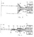
- FIG. 1is transverse view taken through a painting booth having a system of paint applicators that can be adjusted by the use of a measuring tool constructed according to the present invention.
- FIG. 2is a longitudinal sectional view taken through a measuring tool embodying the invention.
- FIG. 3is a view showing a typical spatial relationship between a paint applicator and auto body surface during a painting operation.
- FIG. 4is a view taken in the same direction as FIG. 3, but with a measuring tool of the present invention installed on the paint applicator.
- FIG. 1there is fragmentarily shown a paint spray booth for painting an auto body 10 in a vehicle production environment.
- the auto bodyis placed on a conveyor 12 , which moves slowly through the paint booth past banks of paint applicators 14 stationed at various locations along the booth.
- paint applicators 14stationed at various locations along the booth.
- Some painting operationsare performed manually by human technicians.
- Each paint applicator 14is programmed to apply paint to the auto body surface only while the surface to be painted is aligned with the particular applicators.
- the direction of paint flow onto the auto body surfaceis designated by numeral 16 , i.e. normal to the auto body surface.
- the paintflows from the paint applicator head 14 onto the auto body surface as a conical spray of finely divided paint particles.
- the paint applicator 14is an electrostatic spray device, wherein applicator head 18 is a rotary ionizer head having a bowl (or bell) shape, whereby the electrically charged paint powder has a conical spray pattern as it flows from the head toward the auto body surface.
- the paint applicatorcan be constructed generally as shown in U.S. Pat. No. 5,353,995.
- the paint applicatorshould be spaced a predetermined distance 20 from the auto body surface.
- the applicator—auto body surface spacing 20can vary for different applicators in the system.
- the optimum spacing 20can be eight inch for one applicator and nine inch for another applicator. Spacing distance 20 will typically vary from eight inch to ten inch, in one half inch increments.
- the spacing distances 20 between the auto body surfaces and the individual paint applicators 14would tend to vary incrementally, due to the fact the auto body surface is contoured or sloped toward or away from the auto body centerline 22 , i.e the auto body surfaces are curved, not flat.
- at least some of the paint applicatorscan be programmed to move incrementally toward or away from the auto body center line 22 as the auto body is moved past the respective applicators.
- the paint applicatorsmay be shifted incrementally back and forth, e.g. by rack—and—pinion mechanisms, as indicated by arrows 24 in FIG. 1 .
- the present inventionis concerned with a low cost manual tool that can be temporarily attached to each paint applicator to measure the distance 20 between the applicator and the auto body surface.
- the distance—measuring operation for all paint applicators in the systemcan be carried out on a pre-established schedule (e.g. Monthly), or intermittently when variations in work product quality suggest the need for readjustment of one of more paint applicators in the system.
- FIG. 3illustrates the spatial relation between a typical paint applicator 14 and an auto body surface 30 .
- the applicator head 29is spaced from an auto body surface 30 by a spatial distance 20 .
- a measuring tool of the present inventionis then screwed onto the paint applicator body in place of the paint applicator head.
- FIG. 4shows the FIG. 3 construction after the applicator head has been replaced by the measuring too.
- FIG. 2shows some features of the measuring tool that are not apparent from FIG. 4 .
- the paint applicator 14includes a housing 32 for an air turbine 34 that is mounted on a tubular conduit 36 for airborne coating powders traveling in a right—to—left direction. Paint applicator head 18 is removably attached to a tubular conduit 38 that is slidably adjustable on conduit 36 , whereby spray head 18 can be adjusted toward or away from auto body surface 30 .
- One or more set screws 40can be used to retain conduit 38 in adjusted positions on conduit 36 .
- Conduit 38forms a passage member for conveying the fluidized coating powders from passage 36 into the rotary spray head 18 .
- the rotary spray headis connected to a high voltage source for ionizing the fluidized coating powders, as outlined in the aforementioned U.S. Pat. No. 5,353,995.
- Spray head 18may be removably attached to conduit 38 by a threaded connection that includes an internal female thread on the hub portion of spray head 18 and a male thread on the end portion of conduit 38 .
- the measuring tool of the present inventioncan be temporarily attached to conduit 38 , as shown in FIG. 4 .
- FIG. 2shows some features of a measuring tool constructed according to the invention.
- the toolincludes an elongated probe 44 extending through a mounting fixture 46 .
- the probeincludes a wand support rod 48 and a rod—like deflectable wand 50 normally aligned with the support rod.
- a coil spring 52tightly encircles adjacent end areas of support rod 48 and wand 50 , whereby the wand forms a deflectable extension of rod 48 .
- wand 50is axially aligned with support rod 48 , as shown in FIG. 2 . Should the auto body forcibly contact tip 53 of wand 50 , the wand will deflect, as indicated by dashed line 50 A in FIG, 2 .
- Wand 50is preferably formed of relatively soft plastic or hard rubber, such that when the tip 53 of the wand is brought into rubbing contact with auto body surface 30 the surface will not be scratched.
- Tip 53 of the wandis preferably spherical, so that any gap between tip 53 and the auto body surface is readily observable.
- Mounting fixture 46includes an annular abutment sleeve 55 slidable on wand support rod 48 , and a locking collar 60 rotatable on abutment member 55 .
- a manual set screw 62is threaded transversely through a hole in member 55 to engage a side surface of rod 48 , whereby the rod can be locked in selected positions of axial adjustment relative to sleeve 55 .
- Markingsare provided along the surface of rod 48 to indicate various adjusted positions of the rod relative to end surface 56 of the abutment sleeve 55 . As shown in FIG. 2, there are five markings equidistantly spaced along rod 48 . Each marking takes the form of a narrow annular groove 59 machined into the side surface of rod 48 . The probe is dimensioned so that when rod 48 is adjusted to the FIG. 2 position in abutment sleeve 55 , the tip 53 of the deflectable wand is spaced from end surface 56 by a distance that corresponds to an optimum spacing 20 between a particular paint applicator and auto body surface 30 . Rod 48 can be adjusted leftwardly from the FIG.
- the marking arrangement depicted in FIG. 2accommodates five different applicator—auto body surface spacings 20 (i.e. five different applicator constructions).
- the five different spacingscan range from eight inch (as shown in FIG. 2) to ten inch, in one half inch increments.
- Rotary collar 60has an internal female thread 64 adapted to mesh with a male thread on end of conduit 38 (FIG. 3 ).
- collar 60can be threaded onto conduit 38 to lock the probe 44 in a fixed position relative to conduit 38 .
- Abutment sleeve 55abuts the end of conduit 38 so that reference end surface 56 is spaced a predetermined distance from the end of conduit 38 .
- sleeve 55is dimensioned so that reference surface 56 is in the same plane as the discharge face of spray head 18 (when the spray head is attached to conduit 38 ). Therefore the distance between reference surface 56 and tip 53 of the deflectable wand corresponds to an optimum spacing between the painting applicator and the auto body surface.
- the spray head 18 for each paint applicatoris remove from the associated powder supply conduit 38 .
- a measuring toolis then installed on each paint applicator (e.g. by screwing collar 60 of each receptive tool onto each associated conduit 38 ).
- a representative auto bodyis moved slowly through the paint booth along the normal path used during a painting cycle. During the testing operation the various paint applicators are inactive, in the sense that no coating powders are supplied to the applicators.
- each wand 50will make contact with an associated auto body surface when the auto body reaches the desired painting position in the booth; the wand will be in a non-deflected condition, as depicted in FIG. 2 .
- the associated set screw 40is operated to adjust probe 44 so that tip 53 of the wand contacts the auto body surface without any deflection of the wand.
- Set screw 40is operated to adjust probe 44 so that tip 53 makes contact with the auto body surface 30 , without deflection of the wand.
- the entire complement of paint applicatorscan be calibrated in a single pass of the test vehicle body through the paint booth. It will be appreciated that the various probes 44 will be pre-adjusted in mounting fixtures 46 so that each wand 50 projects the appropriate (optimum) distance from reference surface 56 .
- the calibrating systemis advantageous in that all paint applicators in the system can be tested and adjusted at the same time, whereby the entire surface of each auto body can have an even (consistent) coloration, without color variations from one surface area to another surface area.
- each probe 44can be permanently locked to mounting fixture 46 , so that tip 53 of the wand is spaced a fixed predetermined distance from reference surface 56 .
- a differently dimensioned toolwould be used for each particular paint applicator.
Landscapes
- Physics & Mathematics (AREA)
- General Physics & Mathematics (AREA)
- Spray Control Apparatus (AREA)
Abstract
Description
Claims (14)
Priority Applications (1)
| Application Number | Priority Date | Filing Date | Title |
|---|---|---|---|
| US09/546,767US6378220B1 (en) | 2000-04-11 | 2000-04-11 | Measuring tool usable with a paint applicator |
Applications Claiming Priority (1)
| Application Number | Priority Date | Filing Date | Title |
|---|---|---|---|
| US09/546,767US6378220B1 (en) | 2000-04-11 | 2000-04-11 | Measuring tool usable with a paint applicator |
Publications (1)
| Publication Number | Publication Date |
|---|---|
| US6378220B1true US6378220B1 (en) | 2002-04-30 |
Family
ID=24181915
Family Applications (1)
| Application Number | Title | Priority Date | Filing Date |
|---|---|---|---|
| US09/546,767Expired - LifetimeUS6378220B1 (en) | 2000-04-11 | 2000-04-11 | Measuring tool usable with a paint applicator |
Country Status (1)
| Country | Link |
|---|---|
| US (1) | US6378220B1 (en) |
Cited By (22)
| Publication number | Priority date | Publication date | Assignee | Title |
|---|---|---|---|---|
| US20080228294A1 (en)* | 2007-03-13 | 2008-09-18 | Dycom Identity, Llc | Marking system and method with location and/or time tracking |
| US20080234985A1 (en)* | 2004-02-05 | 2008-09-25 | Trinity Industrial Corporation | Non-Adhered Paint Calculation Method and Solvent Weight Calculation Method |
| US20080245299A1 (en)* | 2007-04-04 | 2008-10-09 | Dycom Identity, Llc | Marking system and method |
| US20090210098A1 (en)* | 2007-03-13 | 2009-08-20 | Nielsen Steven E | Marking apparatus and methods for creating an electronic record of marking apparatus operations |
| US20100086677A1 (en)* | 2008-10-02 | 2010-04-08 | Certusview Technologies, Llc | Methods and apparatus for generating an electronic record of a marking operation based on marking device actuations |
| US20100088031A1 (en)* | 2008-10-02 | 2010-04-08 | Certusview Technologies, Llc | Methods and apparatus for generating an electronic record of environmental landmarks based on marking device actuations |
| US20100090700A1 (en)* | 2008-10-02 | 2010-04-15 | Certusview Technologies, Llc | Methods and apparatus for displaying an electronic rendering of a locate operation based on an electronic record of locate information |
| US20100272885A1 (en)* | 2006-08-16 | 2010-10-28 | SeekTech, Inc., a California corporation | Marking Paint Applicator for Portable Locator |
| US20110045175A1 (en)* | 2009-08-20 | 2011-02-24 | Certusview Technologies, Llc | Methods and marking devices with mechanisms for indicating and/or detecting marking material color |
| USD634656S1 (en) | 2010-03-01 | 2011-03-22 | Certusview Technologies, Llc | Shaft of a marking device |
| USD634657S1 (en) | 2010-03-01 | 2011-03-22 | Certusview Technologies, Llc | Paint holder of a marking device |
| USD634655S1 (en) | 2010-03-01 | 2011-03-22 | Certusview Technologies, Llc | Handle of a marking device |
| USD643321S1 (en) | 2010-03-01 | 2011-08-16 | Certusview Technologies, Llc | Marking device |
| US8311765B2 (en) | 2009-08-11 | 2012-11-13 | Certusview Technologies, Llc | Locating equipment communicatively coupled to or equipped with a mobile/portable device |
| US8442766B2 (en) | 2008-10-02 | 2013-05-14 | Certusview Technologies, Llc | Marking apparatus having enhanced features for underground facility marking operations, and associated methods and systems |
| USD684067S1 (en) | 2012-02-15 | 2013-06-11 | Certusview Technologies, Llc | Modular marking device |
| US8473209B2 (en) | 2007-03-13 | 2013-06-25 | Certusview Technologies, Llc | Marking apparatus and marking methods using marking dispenser with machine-readable ID mechanism |
| US8620572B2 (en) | 2009-08-20 | 2013-12-31 | Certusview Technologies, Llc | Marking device with transmitter for triangulating location during locate operations |
| US8620616B2 (en) | 2009-08-20 | 2013-12-31 | Certusview Technologies, Llc | Methods and apparatus for assessing marking operations based on acceleration information |
| US8626571B2 (en) | 2009-02-11 | 2014-01-07 | Certusview Technologies, Llc | Management system, and associated methods and apparatus, for dispatching tickets, receiving field information, and performing a quality assessment for underground facility locate and/or marking operations |
| US9448555B2 (en) | 2012-06-15 | 2016-09-20 | Toyota Motor Engineering & Manufacturing North America, Inc. | Systems, assemblies, and methods for programming robotic systems |
| US20220347706A1 (en)* | 2016-08-08 | 2022-11-03 | Alexander I. Jittu | Paint/coating applicator locating apparatus and method |
Citations (16)
| Publication number | Priority date | Publication date | Assignee | Title |
|---|---|---|---|---|
| US2232824A (en) | 1940-03-28 | 1941-02-25 | John B Maher | Measuring pole |
| US2356544A (en) | 1943-06-02 | 1944-08-22 | Carl G Swanson | Extensible rule |
| US2540292A (en) | 1945-07-21 | 1951-02-06 | Dayton S Ritchie | Tool |
| US3709190A (en) | 1970-02-14 | 1973-01-09 | Ransburg Gmbh | Coating apparatus |
| US4218824A (en)* | 1979-03-29 | 1980-08-26 | Schaefer Deane R | Guard opening gauge |
| US4543732A (en)* | 1984-01-20 | 1985-10-01 | Acer Automation Company | Automatic nulling LVDT probe |
| US4614356A (en)* | 1985-09-23 | 1986-09-30 | Roy Mills | Apparatus for aligning hitches of towing and towed vehicles |
| US4982897A (en) | 1986-08-15 | 1991-01-08 | Iwata Air Compressor Mfg. Co., Ltd. | Spraying method and apparatus employed therefor |
| US5103761A (en) | 1988-05-26 | 1992-04-14 | Honda Giken Kogyo Kabushiki Kaisha | Coating apparatus |
| US5186119A (en)* | 1992-05-01 | 1993-02-16 | Markers, Inc. | Modular marking system for athletic fields |
| US5207175A (en)* | 1992-03-17 | 1993-05-04 | Garbis Andonian | Marker post |
| US5240745A (en) | 1986-04-01 | 1993-08-31 | Honda Giken Kogyo Kabushiki Kaisha | Method for uniformly painting an object with moving spray guns spaced a constant distance from the surface of the object |
| US5645895A (en) | 1988-09-05 | 1997-07-08 | Honda Giken Kogyo Kabushiki Kaisha | Method for painting a vehicle body |
| US5744190A (en)* | 1994-11-18 | 1998-04-28 | Sames S.A. | Process and device for spraying a coating product |
| US5876803A (en)* | 1993-11-22 | 1999-03-02 | Cegelec AEG Anlagen--und Automatisierungstechnik GmbH | Process and device for controlling a multiplicity of spray tools used in surface coating of vehicles or parts thereof |
| US6318288B1 (en)* | 2000-02-01 | 2001-11-20 | James B. Aspinwall | Vehicle bumper locator |
- 2000
- 2000-04-11USUS09/546,767patent/US6378220B1/ennot_activeExpired - Lifetime
Patent Citations (16)
| Publication number | Priority date | Publication date | Assignee | Title |
|---|---|---|---|---|
| US2232824A (en) | 1940-03-28 | 1941-02-25 | John B Maher | Measuring pole |
| US2356544A (en) | 1943-06-02 | 1944-08-22 | Carl G Swanson | Extensible rule |
| US2540292A (en) | 1945-07-21 | 1951-02-06 | Dayton S Ritchie | Tool |
| US3709190A (en) | 1970-02-14 | 1973-01-09 | Ransburg Gmbh | Coating apparatus |
| US4218824A (en)* | 1979-03-29 | 1980-08-26 | Schaefer Deane R | Guard opening gauge |
| US4543732A (en)* | 1984-01-20 | 1985-10-01 | Acer Automation Company | Automatic nulling LVDT probe |
| US4614356A (en)* | 1985-09-23 | 1986-09-30 | Roy Mills | Apparatus for aligning hitches of towing and towed vehicles |
| US5240745A (en) | 1986-04-01 | 1993-08-31 | Honda Giken Kogyo Kabushiki Kaisha | Method for uniformly painting an object with moving spray guns spaced a constant distance from the surface of the object |
| US4982897A (en) | 1986-08-15 | 1991-01-08 | Iwata Air Compressor Mfg. Co., Ltd. | Spraying method and apparatus employed therefor |
| US5103761A (en) | 1988-05-26 | 1992-04-14 | Honda Giken Kogyo Kabushiki Kaisha | Coating apparatus |
| US5645895A (en) | 1988-09-05 | 1997-07-08 | Honda Giken Kogyo Kabushiki Kaisha | Method for painting a vehicle body |
| US5207175A (en)* | 1992-03-17 | 1993-05-04 | Garbis Andonian | Marker post |
| US5186119A (en)* | 1992-05-01 | 1993-02-16 | Markers, Inc. | Modular marking system for athletic fields |
| US5876803A (en)* | 1993-11-22 | 1999-03-02 | Cegelec AEG Anlagen--und Automatisierungstechnik GmbH | Process and device for controlling a multiplicity of spray tools used in surface coating of vehicles or parts thereof |
| US5744190A (en)* | 1994-11-18 | 1998-04-28 | Sames S.A. | Process and device for spraying a coating product |
| US6318288B1 (en)* | 2000-02-01 | 2001-11-20 | James B. Aspinwall | Vehicle bumper locator |
Cited By (50)
| Publication number | Priority date | Publication date | Assignee | Title |
|---|---|---|---|---|
| US20080234985A1 (en)* | 2004-02-05 | 2008-09-25 | Trinity Industrial Corporation | Non-Adhered Paint Calculation Method and Solvent Weight Calculation Method |
| US20100272885A1 (en)* | 2006-08-16 | 2010-10-28 | SeekTech, Inc., a California corporation | Marking Paint Applicator for Portable Locator |
| US20100094553A1 (en)* | 2007-03-13 | 2010-04-15 | Certusview Technologies, Llc | Systems and methods for using location data and/or time data to electronically display dispensing of markers by a marking system or marking tool |
| US8401791B2 (en) | 2007-03-13 | 2013-03-19 | Certusview Technologies, Llc | Methods for evaluating operation of marking apparatus |
| US7640105B2 (en) | 2007-03-13 | 2009-12-29 | Certus View Technologies, LLC | Marking system and method with location and/or time tracking |
| US8700325B2 (en) | 2007-03-13 | 2014-04-15 | Certusview Technologies, Llc | Marking apparatus and methods for creating an electronic record of marking operations |
| US8478523B2 (en) | 2007-03-13 | 2013-07-02 | Certusview Technologies, Llc | Marking apparatus and methods for creating an electronic record of marking apparatus operations |
| US8473209B2 (en) | 2007-03-13 | 2013-06-25 | Certusview Technologies, Llc | Marking apparatus and marking methods using marking dispenser with machine-readable ID mechanism |
| US20080228294A1 (en)* | 2007-03-13 | 2008-09-18 | Dycom Identity, Llc | Marking system and method with location and/or time tracking |
| US8775077B2 (en) | 2007-03-13 | 2014-07-08 | Certusview Technologies, Llc | Systems and methods for using location data to electronically display dispensing of markers by a marking system or marking tool |
| US8407001B2 (en) | 2007-03-13 | 2013-03-26 | Certusview Technologies, Llc | Systems and methods for using location data to electronically display dispensing of markers by a marking system or marking tool |
| US9086277B2 (en) | 2007-03-13 | 2015-07-21 | Certusview Technologies, Llc | Electronically controlled marking apparatus and methods |
| US20090210098A1 (en)* | 2007-03-13 | 2009-08-20 | Nielsen Steven E | Marking apparatus and methods for creating an electronic record of marking apparatus operations |
| US8903643B2 (en) | 2007-03-13 | 2014-12-02 | Certusview Technologies, Llc | Hand-held marking apparatus with location tracking system and methods for logging geographic location of same |
| US20080245299A1 (en)* | 2007-04-04 | 2008-10-09 | Dycom Identity, Llc | Marking system and method |
| US8060304B2 (en) | 2007-04-04 | 2011-11-15 | Certusview Technologies, Llc | Marking system and method |
| US8374789B2 (en) | 2007-04-04 | 2013-02-12 | Certusview Technologies, Llc | Systems and methods for using marking information to electronically display dispensing of markers by a marking system or marking tool |
| US8386178B2 (en) | 2007-04-04 | 2013-02-26 | Certusview Technologies, Llc | Marking system and method |
| US8280631B2 (en) | 2008-10-02 | 2012-10-02 | Certusview Technologies, Llc | Methods and apparatus for generating an electronic record of a marking operation based on marking device actuations |
| US8361543B2 (en) | 2008-10-02 | 2013-01-29 | Certusview Technologies, Llc | Methods and apparatus for displaying an electronic rendering of a marking operation based on an electronic record of marking information |
| US8770140B2 (en) | 2008-10-02 | 2014-07-08 | Certusview Technologies, Llc | Marking apparatus having environmental sensors and operations sensors for underground facility marking operations, and associated methods and systems |
| US8965700B2 (en) | 2008-10-02 | 2015-02-24 | Certusview Technologies, Llc | Methods and apparatus for generating an electronic record of environmental landmarks based on marking device actuations |
| US8400155B2 (en) | 2008-10-02 | 2013-03-19 | Certusview Technologies, Llc | Methods and apparatus for displaying an electronic rendering of a locate operation based on an electronic record of locate information |
| US9542863B2 (en) | 2008-10-02 | 2017-01-10 | Certusview Technologies, Llc | Methods and apparatus for generating output data streams relating to underground utility marking operations |
| US8442766B2 (en) | 2008-10-02 | 2013-05-14 | Certusview Technologies, Llc | Marking apparatus having enhanced features for underground facility marking operations, and associated methods and systems |
| US8457893B2 (en) | 2008-10-02 | 2013-06-04 | Certusview Technologies, Llc | Methods and apparatus for generating an electronic record of a marking operation including service-related information and/or ticket information |
| US8731830B2 (en) | 2008-10-02 | 2014-05-20 | Certusview Technologies, Llc | Marking apparatus for receiving environmental information regarding underground facility marking operations, and associated methods and systems |
| US8467969B2 (en) | 2008-10-02 | 2013-06-18 | Certusview Technologies, Llc | Marking apparatus having operational sensors for underground facility marking operations, and associated methods and systems |
| US20100090700A1 (en)* | 2008-10-02 | 2010-04-15 | Certusview Technologies, Llc | Methods and apparatus for displaying an electronic rendering of a locate operation based on an electronic record of locate information |
| US8478524B2 (en) | 2008-10-02 | 2013-07-02 | Certusview Technologies, Llc | Methods and apparatus for dispensing marking material in connection with underground facility marking operations based on environmental information and/or operational information |
| US8478525B2 (en) | 2008-10-02 | 2013-07-02 | Certusview Technologies, Llc | Methods, apparatus, and systems for analyzing use of a marking device by a technician to perform an underground facility marking operation |
| US20100088031A1 (en)* | 2008-10-02 | 2010-04-08 | Certusview Technologies, Llc | Methods and apparatus for generating an electronic record of environmental landmarks based on marking device actuations |
| US8612148B2 (en) | 2008-10-02 | 2013-12-17 | Certusview Technologies, Llc | Marking apparatus configured to detect out-of-tolerance conditions in connection with underground facility marking operations, and associated methods and systems |
| US20100086677A1 (en)* | 2008-10-02 | 2010-04-08 | Certusview Technologies, Llc | Methods and apparatus for generating an electronic record of a marking operation based on marking device actuations |
| US8626571B2 (en) | 2009-02-11 | 2014-01-07 | Certusview Technologies, Llc | Management system, and associated methods and apparatus, for dispatching tickets, receiving field information, and performing a quality assessment for underground facility locate and/or marking operations |
| US8731999B2 (en) | 2009-02-11 | 2014-05-20 | Certusview Technologies, Llc | Management system, and associated methods and apparatus, for providing improved visibility, quality control and audit capability for underground facility locate and/or marking operations |
| US9185176B2 (en) | 2009-02-11 | 2015-11-10 | Certusview Technologies, Llc | Methods and apparatus for managing locate and/or marking operations |
| US8311765B2 (en) | 2009-08-11 | 2012-11-13 | Certusview Technologies, Llc | Locating equipment communicatively coupled to or equipped with a mobile/portable device |
| US9097522B2 (en) | 2009-08-20 | 2015-08-04 | Certusview Technologies, Llc | Methods and marking devices with mechanisms for indicating and/or detecting marking material color |
| US8620572B2 (en) | 2009-08-20 | 2013-12-31 | Certusview Technologies, Llc | Marking device with transmitter for triangulating location during locate operations |
| US20110045175A1 (en)* | 2009-08-20 | 2011-02-24 | Certusview Technologies, Llc | Methods and marking devices with mechanisms for indicating and/or detecting marking material color |
| US8620616B2 (en) | 2009-08-20 | 2013-12-31 | Certusview Technologies, Llc | Methods and apparatus for assessing marking operations based on acceleration information |
| USD634655S1 (en) | 2010-03-01 | 2011-03-22 | Certusview Technologies, Llc | Handle of a marking device |
| USD634656S1 (en) | 2010-03-01 | 2011-03-22 | Certusview Technologies, Llc | Shaft of a marking device |
| USD634657S1 (en) | 2010-03-01 | 2011-03-22 | Certusview Technologies, Llc | Paint holder of a marking device |
| USD643321S1 (en) | 2010-03-01 | 2011-08-16 | Certusview Technologies, Llc | Marking device |
| USD684067S1 (en) | 2012-02-15 | 2013-06-11 | Certusview Technologies, Llc | Modular marking device |
| US9448555B2 (en) | 2012-06-15 | 2016-09-20 | Toyota Motor Engineering & Manufacturing North America, Inc. | Systems, assemblies, and methods for programming robotic systems |
| US20220347706A1 (en)* | 2016-08-08 | 2022-11-03 | Alexander I. Jittu | Paint/coating applicator locating apparatus and method |
| US11554382B2 (en)* | 2016-08-08 | 2023-01-17 | Alexander I. Jittu | Paint/coating applicator locating apparatus and method |
Similar Documents
| Publication | Publication Date | Title |
|---|---|---|
| US6378220B1 (en) | Measuring tool usable with a paint applicator | |
| US9914144B2 (en) | Color coded nozzle adapter and locator tool | |
| FI84027B (en) | ANORDING FOR ELECTRICAL EQUIPMENT IN THE FOEREMAOL. | |
| US5333506A (en) | Gauge for measuring the atomization air pressure in a paint spray gun | |
| NO913451L (en) | Nozzle cap for an adhesive dispenser. | |
| GB1506676A (en) | Spray nozzle assembly | |
| US11554382B2 (en) | Paint/coating applicator locating apparatus and method | |
| US4899938A (en) | Liquid spray nozzle adapter | |
| JPH0361507B2 (en) | ||
| US8273417B2 (en) | Spray coating system and method | |
| JP5025467B2 (en) | Spray nozzle with alignment key | |
| US3767116A (en) | Nozzle for electrostatic powder spraying apparatus | |
| CA3081644A1 (en) | Spraying device and method for adjusting the spraying device | |
| US4433296A (en) | Electrostatic system analyzer | |
| CN102510776A (en) | Method for controlling the function of a rotary atomizer, and corresponding coating installation | |
| JP2010512994A (en) | Identification of fluid application equipment by color | |
| KR970001789B1 (en) | Electrostatic spray coating apparatus | |
| DE3709508A1 (en) | Apparatus for the electrostatic coating of workpieces | |
| US5099784A (en) | Contact marker system | |
| JPS5851970Y2 (en) | Guide antenna for painting | |
| US20100243757A1 (en) | Device for positioning spray-gun air cap | |
| KR102155799B1 (en) | Teaching tool for painting robot | |
| JPS6054754A (en) | Electrostatic sprayer | |
| CN104220175B (en) | Spray Tip Holder, Nozzle Assembly and Spray Gun | |
| AU603253B2 (en) | Frame fixture for camouflage painting |
Legal Events
| Date | Code | Title | Description |
|---|---|---|---|
| AS | Assignment | Owner name:DAIMLERCHRYSLER CORPORATION, MICHIGAN Free format text:ASSIGNMENT OF ASSIGNORS INTEREST;ASSIGNORS:BAIOFF, DANNY;BOUCHER, GIL;TIESSEN, DAVID A.;REEL/FRAME:010772/0218 Effective date:20000401 | |
| STCF | Information on status: patent grant | Free format text:PATENTED CASE | |
| FPAY | Fee payment | Year of fee payment:4 | |
| AS | Assignment | Owner name:WILMINGTON TRUST COMPANY, DELAWARE Free format text:GRANT OF SECURITY INTEREST IN PATENT RIGHTS - FIRST PRIORITY;ASSIGNOR:CHRYSLER LLC;REEL/FRAME:019773/0001 Effective date:20070803 Owner name:WILMINGTON TRUST COMPANY,DELAWARE Free format text:GRANT OF SECURITY INTEREST IN PATENT RIGHTS - FIRST PRIORITY;ASSIGNOR:CHRYSLER LLC;REEL/FRAME:019773/0001 Effective date:20070803 | |
| AS | Assignment | Owner name:WILMINGTON TRUST COMPANY, DELAWARE Free format text:GRANT OF SECURITY INTEREST IN PATENT RIGHTS - SECOND PRIORITY;ASSIGNOR:CHRYSLER LLC;REEL/FRAME:019767/0810 Effective date:20070803 Owner name:WILMINGTON TRUST COMPANY,DELAWARE Free format text:GRANT OF SECURITY INTEREST IN PATENT RIGHTS - SECOND PRIORITY;ASSIGNOR:CHRYSLER LLC;REEL/FRAME:019767/0810 Effective date:20070803 | |
| AS | Assignment | Owner name:DAIMLERCHRYSLER COMPANY LLC, MICHIGAN Free format text:CHANGE OF NAME;ASSIGNOR:DAIMLERCHRYSLER CORPORATION;REEL/FRAME:021711/0543 Effective date:20070329 | |
| AS | Assignment | Owner name:CHRYSLER LLC, MICHIGAN Free format text:CHANGE OF NAME;ASSIGNOR:DAIMLERCHRYSLER COMPANY LLC;REEL/FRAME:021775/0462 Effective date:20070727 | |
| AS | Assignment | Owner name:US DEPARTMENT OF THE TREASURY, DISTRICT OF COLUMBI Free format text:GRANT OF SECURITY INTEREST IN PATENT RIGHTS - THIR;ASSIGNOR:CHRYSLER LLC;REEL/FRAME:022259/0188 Effective date:20090102 Owner name:US DEPARTMENT OF THE TREASURY,DISTRICT OF COLUMBIA Free format text:GRANT OF SECURITY INTEREST IN PATENT RIGHTS - THIR;ASSIGNOR:CHRYSLER LLC;REEL/FRAME:022259/0188 Effective date:20090102 | |
| AS | Assignment | Owner name:CHRYSLER LLC, MICHIGAN Free format text:RELEASE BY SECURED PARTY;ASSIGNOR:US DEPARTMENT OF THE TREASURY;REEL/FRAME:022902/0310 Effective date:20090608 Owner name:CHRYSLER LLC,MICHIGAN Free format text:RELEASE BY SECURED PARTY;ASSIGNOR:US DEPARTMENT OF THE TREASURY;REEL/FRAME:022902/0310 Effective date:20090608 | |
| AS | Assignment | Owner name:CHRYSLER LLC, MICHIGAN Free format text:RELEASE OF SECURITY INTEREST IN PATENT RIGHTS - FIRST PRIORITY;ASSIGNOR:WILMINGTON TRUST COMPANY;REEL/FRAME:022910/0498 Effective date:20090604 Owner name:CHRYSLER LLC, MICHIGAN Free format text:RELEASE OF SECURITY INTEREST IN PATENT RIGHTS - SECOND PRIORITY;ASSIGNOR:WILMINGTON TRUST COMPANY;REEL/FRAME:022910/0740 Effective date:20090604 Owner name:NEW CARCO ACQUISITION LLC, MICHIGAN Free format text:ASSIGNMENT OF ASSIGNORS INTEREST;ASSIGNOR:CHRYSLER LLC;REEL/FRAME:022915/0001 Effective date:20090610 Owner name:THE UNITED STATES DEPARTMENT OF THE TREASURY, DIST Free format text:SECURITY AGREEMENT;ASSIGNOR:NEW CARCO ACQUISITION LLC;REEL/FRAME:022915/0489 Effective date:20090610 Owner name:CHRYSLER LLC,MICHIGAN Free format text:RELEASE OF SECURITY INTEREST IN PATENT RIGHTS - FIRST PRIORITY;ASSIGNOR:WILMINGTON TRUST COMPANY;REEL/FRAME:022910/0498 Effective date:20090604 Owner name:CHRYSLER LLC,MICHIGAN Free format text:RELEASE OF SECURITY INTEREST IN PATENT RIGHTS - SECOND PRIORITY;ASSIGNOR:WILMINGTON TRUST COMPANY;REEL/FRAME:022910/0740 Effective date:20090604 Owner name:NEW CARCO ACQUISITION LLC,MICHIGAN Free format text:ASSIGNMENT OF ASSIGNORS INTEREST;ASSIGNOR:CHRYSLER LLC;REEL/FRAME:022915/0001 Effective date:20090610 Owner name:THE UNITED STATES DEPARTMENT OF THE TREASURY,DISTR Free format text:SECURITY AGREEMENT;ASSIGNOR:NEW CARCO ACQUISITION LLC;REEL/FRAME:022915/0489 Effective date:20090610 | |
| AS | Assignment | Owner name:CHRYSLER GROUP LLC, MICHIGAN Free format text:CHANGE OF NAME;ASSIGNOR:NEW CARCO ACQUISITION LLC;REEL/FRAME:022919/0126 Effective date:20090610 Owner name:CHRYSLER GROUP LLC,MICHIGAN Free format text:CHANGE OF NAME;ASSIGNOR:NEW CARCO ACQUISITION LLC;REEL/FRAME:022919/0126 Effective date:20090610 | |
| FPAY | Fee payment | Year of fee payment:8 | |
| AS | Assignment | Owner name:CHRYSLER GROUP LLC, MICHIGAN Free format text:RELEASE BY SECURED PARTY;ASSIGNOR:THE UNITED STATES DEPARTMENT OF THE TREASURY;REEL/FRAME:026343/0298 Effective date:20110524 Owner name:CHRYSLER GROUP GLOBAL ELECTRIC MOTORCARS LLC, NORT Free format text:RELEASE BY SECURED PARTY;ASSIGNOR:THE UNITED STATES DEPARTMENT OF THE TREASURY;REEL/FRAME:026343/0298 Effective date:20110524 | |
| AS | Assignment | Owner name:CITIBANK, N.A., NEW YORK Free format text:SECURITY AGREEMENT;ASSIGNOR:CHRYSLER GROUP LLC;REEL/FRAME:026404/0123 Effective date:20110524 | |
| AS | Assignment | Owner name:CITIBANK, N.A., NEW YORK Free format text:SECURITY AGREEMENT;ASSIGNOR:CHRYSLER GROUP LLC;REEL/FRAME:026435/0652 Effective date:20110524 | |
| FPAY | Fee payment | Year of fee payment:12 | |
| AS | Assignment | Owner name:JPMORGAN CHASE BANK, N.A., ILLINOIS Free format text:SECURITY AGREEMENT;ASSIGNOR:CHRYSLER GROUP LLC;REEL/FRAME:032384/0640 Effective date:20140207 | |
| AS | Assignment | Owner name:FCA US LLC, MICHIGAN Free format text:CHANGE OF NAME;ASSIGNOR:CHRYSLER GROUP LLC;REEL/FRAME:035553/0356 Effective date:20141203 | |
| AS | Assignment | Owner name:FCA US LLC, FORMERLY KNOWN AS CHRYSLER GROUP LLC, Free format text:RELEASE OF SECURITY INTEREST RELEASING SECOND-LIEN SECURITY INTEREST PREVIOUSLY RECORDED AT REEL 026426 AND FRAME 0644, REEL 026435 AND FRAME 0652, AND REEL 032384 AND FRAME 0591;ASSIGNOR:CITIBANK, N.A.;REEL/FRAME:037784/0001 Effective date:20151221 | |
| AS | Assignment | Owner name:FCA US LLC (FORMERLY KNOWN AS CHRYSLER GROUP LLC), Free format text:RELEASE BY SECURED PARTY;ASSIGNOR:CITIBANK, N.A.;REEL/FRAME:042885/0255 Effective date:20170224 | |
| AS | Assignment | Owner name:FCA US LLC (FORMERLY KNOWN AS CHRYSLER GROUP LLC), Free format text:RELEASE BY SECURED PARTY;ASSIGNOR:JPMORGAN CHASE BANK, N.A.;REEL/FRAME:048177/0356 Effective date:20181113 |