US6377715B1 - Data inputting device - Google Patents
Data inputting deviceDownload PDFInfo
- Publication number
- US6377715B1 US6377715B1US09/299,579US29957999AUS6377715B1US 6377715 B1US6377715 B1US 6377715B1US 29957999 AUS29957999 AUS 29957999AUS 6377715 B1US6377715 B1US 6377715B1
- Authority
- US
- United States
- Prior art keywords
- tablet
- image sensor
- image
- casing
- inputting
- Prior art date
- Legal status (The legal status is an assumption and is not a legal conclusion. Google has not performed a legal analysis and makes no representation as to the accuracy of the status listed.)
- Expired - Lifetime
Links
Images


Classifications
- H—ELECTRICITY
- H04—ELECTRIC COMMUNICATION TECHNIQUE
- H04N—PICTORIAL COMMUNICATION, e.g. TELEVISION
- H04N1/00—Scanning, transmission or reproduction of documents or the like, e.g. facsimile transmission; Details thereof
- H04N1/04—Scanning arrangements, i.e. arrangements for the displacement of active reading or reproducing elements relative to the original or reproducing medium, or vice versa
- H04N1/10—Scanning arrangements, i.e. arrangements for the displacement of active reading or reproducing elements relative to the original or reproducing medium, or vice versa using flat picture-bearing surfaces
- H04N1/107—Scanning arrangements, i.e. arrangements for the displacement of active reading or reproducing elements relative to the original or reproducing medium, or vice versa using flat picture-bearing surfaces with manual scanning
- G—PHYSICS
- G06—COMPUTING OR CALCULATING; COUNTING
- G06F—ELECTRIC DIGITAL DATA PROCESSING
- G06F3/00—Input arrangements for transferring data to be processed into a form capable of being handled by the computer; Output arrangements for transferring data from processing unit to output unit, e.g. interface arrangements
- G06F3/01—Input arrangements or combined input and output arrangements for interaction between user and computer
- G06F3/03—Arrangements for converting the position or the displacement of a member into a coded form
- G06F3/033—Pointing devices displaced or positioned by the user, e.g. mice, trackballs, pens or joysticks; Accessories therefor
- G06F3/0354—Pointing devices displaced or positioned by the user, e.g. mice, trackballs, pens or joysticks; Accessories therefor with detection of 2D relative movements between the device, or an operating part thereof, and a plane or surface, e.g. 2D mice, trackballs, pens or pucks
- G06F3/03545—Pens or stylus
- H—ELECTRICITY
- H04—ELECTRIC COMMUNICATION TECHNIQUE
- H04N—PICTORIAL COMMUNICATION, e.g. TELEVISION
- H04N1/00—Scanning, transmission or reproduction of documents or the like, e.g. facsimile transmission; Details thereof
- H04N1/00127—Connection or combination of a still picture apparatus with another apparatus, e.g. for storage, processing or transmission of still picture signals or of information associated with a still picture
- H—ELECTRICITY
- H04—ELECTRIC COMMUNICATION TECHNIQUE
- H04N—PICTORIAL COMMUNICATION, e.g. TELEVISION
- H04N2201/00—Indexing scheme relating to scanning, transmission or reproduction of documents or the like, and to details thereof
- H04N2201/0008—Connection or combination of a still picture apparatus with another apparatus
- H04N2201/0063—Constructional details
Definitions
- the present inventionrelates to a data inputting device for inputting data to a computer, word processor or similar data processor and, more particularly, to a data inputting device for inputting coordinates and images.
- a data inputting device for the above applicationhas been proposed in various forms in the past.
- the data inputting deviceis implemented as a coordinates inputting device or pointing device for inputting coordinates, or an image inputting device for inputting images.
- the pointing devicemay consist of a tablet for detecting coordinates on the basis of capacity coupling, and a pen.
- Various kinds of pointing devices heretofore proposed eachhas a particular principle of operation.
- Japanese Patent Laid-Open Publication No. 4-45481for example, teaches a device which applies shift pulses to scanning lines extending in an X direction and a Y direction, thereby generating loop currents. This type of device detects the coordinates of a n intersection which a pen is positioned, on the basis of the pulse application timing and the pen detection timing.
- Japanese Patent Laid-Open Publication No. 63-184823discloses a device capable of determining the position of a pen by use of optical fibers arranged in the vertical and horizontal directions, and a pair of image sensors.
- Japanese Patent Laid-Open Publication No. 4-369016proposes a device having a pen whose point issues light, and a protection glass. When the pen is pressed against the protection glass, the coordinates on the glass are detected by a bidimensional CCD sensor.
- Japanese Patent Laid-Open Publication No. 4-195624teaches a device having transparent electrodes arranged in the X and Y directions, and an electronic pen having a capacity detecting circuit at the point thereof.
- Japanese Patent Laid-Open Publication No. 63-257020discloses a device having a tablet implemented as a transparent vibration transfer plate, and a vibration pen. After the vibration transfer plate has been laid on a document, the vibration pen is put on the plate. The vibration of the pen is transferred via the plate to a plurality of sensors arranged on the plate, so that coordinates can be detected.
- a handy scannerwhich is a specific form of the image inputting device has a plurality of rollers, a linear image sensor, and an encoder.
- the rollersroll on the surface of a document.
- the image sensorhas a width covering an image reading width and is so positioned as to adjoin the document.
- the encoderis used to sense the movement of the image sensor in the subscanning direction.
- a particular inputting unithas been developed for each of the pointing devices and image inputting devices described above.
- modern image processors with advanced functionsallow data to be input therein in various modes
- the two inputting unitsmust be held by hand alternately or must be replaced with each other on the desk, resulting in inefficient manipulation.
- the encoder responsive to the movement in the subscanning direction, and rollers for stabilizing the travel of the scannerare arranged around the linear image sensor Hence, the scanner cannot be reduced in width, i.e., length in the subscanning direction. As a result, the scanner conceals the image reading portion over a substantial width including the line being input. This prevents the operator from accurately seeing the portion being read.
- data available with the encoder built in the scannerare not absolute coordinates representative of the reading surface, but they are relative coordinates, i.e., amounts of rolling or movement. Hence, once the scanner is brought out of contact with the reading surface, it is necessary for the operator to match the beginning of the portion to be read next to the end of the portion previously read. This is further aggravated by the great width of the handy scanner.
- an object of the present inventionto provide a data inputting device having a single inputting unit capable of selectively inputting coordinates or an image.
- a data inputting deviceincludes a tablet.
- a tablet drivercauses the tablet to generate a physical change representative of a position on the tablet.
- An image sensorreads a document laid on the tablet. Position detecting arrangements respectively adjoin opposite ends of the image sensor and analyze, while the document is read by the image sensor, the physical change generated by the tablet to thereby determine the position of the image sensor relative to the tablet.
- a data inputting deviceincludes a tablet.
- a tablet drivercauses the tablet to generate a physical change representative of a position on the tablet.
- An image sensorreads a document laid on the tablet.
- First position detecting arrangementsassigned to image reading, respectively adjoin opposite ends of the image sensor, and analyze, while the document is read by the image sensor, the physical change generated by the tablet to thereby determine the position of the image sensor relative to the tablet.
- a second position detecting arrangement, assigned to inputting coordinatesincludes, a pen point configuration, and is accommodated in the same casing as the first position detecting arrangements, and analyzes, when put on the tablet, the physical change to thereby determine a position on the tablet.
- a data inputting devicecomprises a casing having a pen configuration and formed with an opening, a linear image sensor facing the opening and extending along an axis of the casing and a movable for closing and exposing the opening.
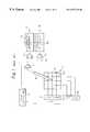
- FIG. 1is a schematic block diagram showing a conventional coordinates inputting device using a pen
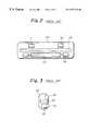
- FIG. 2is a bottom view of a conventional handy scanner which is a specific form of an image inputting device
- FIG. 3is a side elevation showing the constituents of the scanner of FIG. 2;
- FIG. 4is a perspective view demonstrating how a first embodiment of the data inputting device in accordance w it h the present invention is used in a coordinates input mode;
- FIG. 5is a view similar to FIG. 4, showing how the device is used in an image input mode
- FIG. 6shows the general configuration of a pen type inputting unit included in the embodiment
- FIG. 7is a cross-section of a casing included in the inputting unit of FIG. 6;
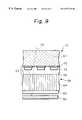
- FIG. 8is a perspective view of a linear image sensor included in the inputting unit of FIG. 6;
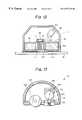
- FIG. 9is a fragmentary section in an x-z plane of FIG. 8, showing a relation between the image sensor and the surface of a document;
- FIG. 10shows a modified form of the first embodiment
- FIG. 11shows a second embodiment of the present invention
- FIG. 12is a section showing a third embodiment of the present invention.
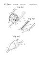
- FIG. 13shows one of miniature handy scanners
- FIGS. 14A-14Cshow a fourth embodiment of the present invention constituting an improvement over the handy scanner of FIG. 13;
- FIGS. 15A and 15Bshow a fifth embodiment of the present invention.
- FIGS. 16A and 16Bshow a sixth embodiment of the present invention also constituting an improvement over the conventional handy scanner.
- the pointing deviceincludes a tablet 11 for detecting coordinates on the basis of capacity coupling.
- the tablet 11has a plurality of electrodes 12 x and a plurality of electrodes 12 y extending perpendicularly to each other.
- the electrodes 12 x and 12 yare arranged at predetermined intervals.
- the vertical electrodes 12 xas viewed in the figure, are connected to an X driver 13 x while the horizontal electrodes 12 y are connected to a Y driver 13 y .
- the X driver 13 xselectively applies a scanning pulse to one of the electrodes 12 x at a time.
- the Y driver 13 yselectively applies a scanning pulse to one of the electrodes 12 y at a time.
- a timing controller 14causes each of the X driver 13 x and Y driver 13 y to feed the scanning pulses at a particular timing.
- an electronic pen 15has its tip or point put on the tablet 11 in accordance with desired coordinates.
- the pen 15includes an electrode, not shown, at the point thereof, so that a charge is induced in the electrode on the basis of capacity.
- the induced chargeis detected by an amplifier 16 and then applied to an X differential amplifier 17 x and a Y differential amplifier 17 y .
- the differential amplifiers 17 x and 17 yhave their one input opposite in direction connected to ground, as illustrated. In this condition, the amplifier 17 x detects a change in charge in the X direction while the amplifier 17 y detects a change in charge in the Y direction.
- the outputs of the differential amplifiers 17 x and 17 yare fed to an X coordinates determining circuit 18 x and a Y coordinates determining circuit 18 y , respectively.
- the timing controller 14delivers to each of the coordinates determining circuits 18 x and 18 y a timing signal indicative of the timing for applying the pulses.
- the position of the pen 15 on the tablet 11is detected on the basis of a relation between the time when the charge is maximum and the electrodes 12 x and 12 y .
- the result of this detectionis output from an X coordinate output terminal 19 x and a Y coordinate output terminal 19 y.
- the scanning pulseis sequentially applied to the electrodes 12 x and 12 y which are perpendicular to each other.
- the charge detected by the pen 15increases in absolute value with a decrease in the distance between the position where the point of the pen 11 is located on the tablet 11 and the electrodes 12 x and 12 y .
- the pen 15is capable of inputting coordinates if the differential amplifiers 17 x and 17 y are each provided with, e.g., a counter for counting an interval between the time when the timing controller 14 starts scanning for one period and the time when the output of the differential amplifier 17 x or 17 y becomes maximum in the above period.
- FIG. 2shows a conventional handy scanner which is a specific form of an image inputting device.
- the handy scannerhas rollers 21 - 23 rollable on an image reading surface and slightly protruding from the bottom of a casing 24 .
- the roller 23is longer than the rollers 21 and 22 and extends in parallel to the common axis of the rollers 21 and 22 .
- a linear image sensor 25is between the rollers 21 and 22 and the roller 23 .
- the image sensor 25extends over an image reading width and adjoins the image reading surface.
- An encoder 26is provided coaxially with the roller 23 in order to sense the movement of the image sensor 25 in the subscanning direction.
- FIG. 3shows the rollers 22 and 23 , image sensor 25 and encoder 26 in a side elevation.
- the casing 24is held by hand and then moved in the subscanning direction perpendicular to the lengthwise direction of the image sensor 25 .
- the image sensor 25has a number of reading elements arranged thereon in the lengthwise direction. Every time the rollers 21 - 23 roll in an amount corresponding to one pitch in the subscanning direction, the encoder 26 detects it and causes the image sensor 25 to scan the document in the main scanning direction. The resulting image signals representative of a density distribution line by line are combined to produce a bidimensional image.
- the inputting deviceis disadvantageous since both of the two different devices must be put on a desk together, occupying a substantial space.
- the two inputting unitsmust be held by hand alternately or must be replaced with each other on the desk, resulting in inefficient manipulation.
- the problem with the conventional handy scanneris that it cannot be reduced in width, i.e., length in the subscanning direction. Hence, the scanner conceals the image reading area over a substantial width including the line being input. This prevents the operator from accurately seeing the portion being read.
- data available with an encoder built in the scannerare not absolute coordinates representative of the reading surface, but they are relative coordinates, i.e., amounts of rolling or movement. Hence, once the scanner is brought out of contact with the reading surface, the portion to be read next must be matched to the portion previously read.
- the deviceincludes a tablet 31 and a pen type inputting unit 33 connected to the tablet 31 by a cable 32 .
- the coordinates of the position where the pen 33 has contacted the tablet 31is input.
- a document 36is laid on the tablet 31 and, preferably, fixed in place by, e.g., adhesive tapes, not shown. Assume that the operator lays the inputting unit 33 flat on the document 36 in the main scanning direction, as shown in FIG. 5, and then moves it in the subscanning direction 38 .
- a linear image sensorbuilt in the inputting unit 33 sequentially senses the image of the document 36 one line at a time. It is noteworthy that the image reading portion of the inputting unit 33 can be provided with a length smaller than the width of the image reading area of the document 36 . That is, the operator should only repeat image reading a plurality of times in the subscanning direction while causing the adjoining areas to slightly over-lap each ether, just like mopping the floor.
- the tablet 31 shown in FIGS. 4 and 5is essentially similar to the conventional tablet 11 of FIG. 1 and will not be described specifically in order to avoid redundancy.
- the inputting unit 33has a pen-like hollow casing 41 made of transparent plastic or resin.
- An electrode 42is studded on the tip of the casing 41 and detects coordinates on the tablet 31 .
- a switch 43is located on the casing 41 at a position which the operator, holding the casing 41 , will touch with the tip of his or her forefinger. When the operator's forefinger touches the switch 43 , a switching circuit 44 built in the casing 41 senses it and connects the electrode 42 to the input of a first signal detecting circuit 45 .
- the casing 41is a hollow cylinder having a diameter of about 1 cm. Two arcuate portions of the cylinder facing each other are deformed to form first and second flat portions 41 1 and 41 2 , respectively. A slot 52 is formed in the second flat portion 41 2 and extends in the axial direction of the casing 41 over a predetermined reading width.
- the switch 43is positioned in the vicinity of the end of the first flat portion 41 1 .
- a first electrode 47 responsive to a position in the subscanning directionis mounted on the inner periphery of the flat portion 41 2 facing the flat portion 41 1 .
- the switching circuit 44connects the electrode 47 to the input of the signal detecting circuit 45 .
- a second electrode 48also responsive to a position in the subscanning direction, is mounted on the inner periphery of the flat portion 41 2 , FIG. 7, adjacent to the other or rear end of the casing 41 .
- the output of the electrode 48is connected to the input of a second signal detecting circuit 49 .
- the electrodes 47 and 48each detects a position on the tablet 31 , FIGS. 4 and 5, in the subscanning direction.
- the electrodes 47 and 48are identical with the electrode 42 located at the tip of the casing 41 .
- a linear image sensor 51is disposed in the casing 41 between the electrodes 47 and 48 .
- the cable 32is made up of a signal line extending from the image sensor 51 and signal lines respectively extending from the signal detecting circuits 45 and 49 .
- FIG. 8shows the linear image sensor 51 specifically.
- the image sensor 51has a light source section 53 made up of R (Red), G (Green) and B (Blue) LED (Light Emitting Diode) arrays 54 R, 54 G and 54 B, and first condensing lenses 55 R, 55 G and 55 B.
- the LED arrays 54 R, 53 G and 54 Bare parallel to each other and arranged at predetermined intervals.
- the lenses 55 R, 55 G and 55 Brespectively face the LED arrays 54 R- 54 B and condense light issuing from the associated LED arrays 54 R- 54 B to output substantially parallel light.
- a light condensing section 56 , a light-sensitive section 57 , a fiber-optic section 58 , and a protection layer 59are sequentially arranged below the light source section 53 in this order.
- the protection layer 59is located at the slot 52 of the flat portion 412 shown in FIG. 7 . Hence, an image is directly read by the image sensor 51 via the protection layer 59 .
- the condensing section 56has second condensing lenses 61 R, 61 G and 61 B facing the lenses 55 R, 55 G and 55 B, respectively.
- Light from the lenses 61 R, 61 G and 61 Bis incident to the fiber-optic section 58 via the gaps of a light-sensitive element array 63 provided on the underside of a transparent insulative substrate which constitutes the light-sensitive section 57 .
- the fiber-optic section 58has an array of optical fibers 64 extending along the light-sensitive element array 63 (y axis direction) over the entire length of the array 63 .
- the section 58has a width defined by a plurality of optical fibers 64 .
- the light passed through the gaps of the light-sensitive element array 63is routed through the protection layer 59 to the document surface. The resulting reflection from the document surface is incident to the light-sensitive element array 63 .
- FIG. 9is a fragmentary section showing the image sensor 51 in an x-z plane, FIG. 8, in relation to the surface of the document 36 to be read.
- screen layers 72are arranged on the underside of a transparent insulative substrate 71 at predetermined intervals in a comb-like pattern, and each has a predetermined width.
- a light-sensitive element 73is provided on each of the screen layers 72 .
- a protection layer 74is formed on the bottom of the substrate 71 while covering the screen layers 72 and light-sensitive elements 73 . These constitute the light-sensitive element array 63 in combination.
- the light-sensitive section 57is coupled to the fibers 64 via the protection layer 74 while the fiber-optic section 58 substantially closely contacts the surface of the document 36 via the protection layer 59 .
- FIG. 9light 76 from the light source section 53 , FIG. 8, is incident to the transparent insulative substrate 71 .
- the part of the light transmitted through the gaps between the screen layers 72is incident to the upper ends of the fibers 64 and sequentially propagated downward through the fibers 64 to the document 36 in a direction z while being subjected to repeated total reflection.
- the resulting reflection from the document 36is incident to the lower ends of the fibers 64 via the protection layer 59 and sequentially propagated upward through the fibers 64 to the protection layer 74 in the direction z.
- the light from the protection layer 74reaches the light-sensitive elements 73 .
- the image sensor 51senses the density distribution of the document 36 .
- the total dimension of the fiber-optic section 58 and light-sensitive section 57is about 1 mm in the direction z.
- the total dimension of the light-source section 53 and condensing section 56is about 2 mm to about 4 mm in the direction z.
- the overall dimension in the direction zis about 4 mm to about 6 mm and small enough to be accommodated in the casing 41 , FIG. 7, whose diameter is about 1 cm.
- FIG. 4in a coordinates input mode, the operator holds the inputting unit 33 with his or her hand 34 like an ordinary pen, and then moves it on the tablet 31 while maintaining the pen-point electrode 42 in contact with the tablet 31 .
- the operatorcontinuously touches the switch 43 with, e.g., forefinger.
- a signal from the electrode 42is input to the first signal detecting circuit 45 .
- scanning pulsesare sequentially applied to electrodes arranged in the tablet 31 in the X and Y directions, as stated with reference to FIG. 1 .
- the signal detecting circuit 45detects a change in charge in the X direction and a change in charge in the Y direction.
- an X coordinates and a Y coordinates determining circuitrespectively determine the X and Y coordinates of the point where the electrode 42 contacts the tablet 31 . Consequently, the coordinate data determined by the circuit 45 are sent to the previously mentioned signal processor via the cable 32 .
- sequential coordinates data representative of the locus of the electrode 42are sent to the data processor via the cable 32 .
- the operatorholds the intermediate portion of the inputting unit 33 with his or her hand 34 . Then, the operator moves the inputting unit 33 in a predetermined direction (subscanning direction) while maintaining the flat portion 41 2 in contact with the document 36 . In this case, the operator's hand 34 does not touch the switch 43 , so that the switching circuit 44 selects the electrode 47 . In this condition, the signal detecting circuit 45 determines X and Y coordinates where the electrode 47 is located, on the basis of a charge induced in the electrode 47 . The coordinates data are sent to the data processor.
- the other signal detecting circuit 49determines X and Y coordinates where the electrode 48 is located, also on the basis of a charged induced in the electrode 48 . These coordinates data are also sent to the data processor. Further, an image signal output from the image sensor 51 is sent to the image processor.
- the image processortherefore, receives the coordinates data representative of the absolute coordinates of both ends of the image sensor 51 , and the line-by-line image signal.
- the R, G and B LED arrays 54 R- 54 Bsequentially and repeatedly emit respective light.
- the image sensor 51reads color image data out of the document 36 in the form of R, G and B data. Further, the absolute coordinates of both ends of the image sensor 51 are indicative of which portion of the document 36 it is reading. Hence, even when the inputting unit 33 is released from the document 36 during operation, two successive image areas can be readily matched to each other only if the the unit 33 is again moved on the document 36 . Moreover, even when the reading width of the image sensor 51 is smaller than the width of the document 36 , it is only necessary for the inputting unit 33 to be sequentially moved over a plurality of regions assumed on the document 36 in the widthwise direction. This can also be done because the coordinates data are representative of the absolute coordinates of both ends of the image sensor 51 .
- the casing 41is shown as having a cross-section which is the combination of arcuate portions and flat portions.
- the casing 41may be provided with a hexagonal, square, triangular or similar polygonal cross-section.
- FIG. 10shows the casing 41 having a nonagonal cross-section.
- the casing 41has nine faces one of which is formed by the protection layer 59 of the fiber-optic section 58 .
- the protection layer 59directly contacts the document during the course of reading operation.
- a diffuser 81is provided on the top of the light source section 53 in order to diffuse light. In this modified configuration, light sequentially issuing from the LED arrays 54 R, 54 G and 54 B is diffused by the diffuser 81 and then focused onto the document.
- FIG. 11shows the principle of an alternative embodiment of the present invention using electromagnetic transfer.
- a pen type inputting unit 91has a resonance circuit 92 together with the linear image sensor 51 .
- Loop-like coils 95are arranged on a tablet 94 at predetermined intervals, and each extends in the X direction.
- the coils 95are connected to ground at one end and connected to a first switching circuit 96 at the other end.
- the switching circuit 96has a first contact 97 for sequentially selecting the coils 95 at a predetermined period.
- the first contact 97is connected to a second contact 99 included in a second switching circuit 98 .
- the second contact 99selects each of a high frequency generator 101 and a signal detection circuit 102 once.
- Coilsare also arranged in the Y direction on the tablet 94 and connected to a similar switching circuit, although not shown in order to avoid complexity.
- the resonance circuit 92stores the resulting electromagnetic wave as electromagnetic energy for a moment.
- the signal detection circuit 102is selected by the contact 99 in place of the high frequency generator 101 , the electromagnetic energy stored in the resonance circuit 92 is detected by the circuit 102 . This is repeated every time the contact 97 selects the next coil 95 .
- the energy detected by the signal detecting circuit 102is fed to an X coordinates determining circuit 104 . This circuit 104 compares the outputs of the signal detecting circuit 102 as to energy and thereby determines that one of the coils 95 generated the greatest energy is representative of the X coordinate.
- the center of gravity schemecalculates the center of gravity on the basis of the analog outputs of the coils 95 , thereby determining the coordinates indicated by the inputting unit 91 .
- the center of gravity schemeis capable of detecting coordinates with a resolution higher than the pitch of the coils 95 .
- the inputting unitgenerally 111
- the inputting unithas a bottom-open casing 112 accommodating the focusing section 58 therein.
- a screen layer 114covers the bottom of the fiber-optic section 58 except for the lower ends of the fibers 64 .
- a protection layer 115covers the lower ends of the fibers 64 and the screen layer 114 .
- the screen layer 114intercepts extraneous light except for the imagewise reflection from the document 36 .
- a screen layer 114 and a circuit conductor layer 116are formed on the top of the fiber-optic section 58 and respectively positioned at the right-hand side and the left-hand side, as viewed in FIG. 12, with respect to the upper ends of the fibers 64 .
- the circuit conductor layer 116extends as far as substantially the intermediate between the outermost fibers 64 , as seen in FIG. 12.
- a CCD image sensor or similar crystalline Si (silicon) image sensor 118is mounted on the edge of the layer 116 by a connecting part 117 .
- Light-sensitive elements 119are arranged on the bottom of the image sensor 118 and spaced a predetermined distance from the edge of the image sensor 118 . The elements 119 face the upper ends of the fibers 64 .
- a transparent protection layer 121intervenes between the upper ends of the fibers 64 and the light-sensitive elements 119 .
- the light source section 53 identical in construction as the section 53 of the first embodimentis positioned obliquely above the light-sensitive elements 119 and sequentially emit R, G and B light.
- the light issuing from the light source section 53is incident to the upper ends of the fibers 64 via the protection layer 121 .
- the lightis propagated downward through the fibers 64 while being subjected to repeated total reflection, until it reaches the document 36 .
- the resulting reflection from the document 36is incident to the lower ends of the fibers 64 and then propagated upward through the fibers 64 until it reaches the light-sensitive elements 119 .
- This embodimentis different from the first embodiment in that the side of the image sensor 118 carrying the light-sensitive elements 119 is not transparent. This also successfully generates an image signal representative of the density distribution of the document 36 .
- the R, G and B LED arrays used in the embodiments and modifications thereofare only illustrative.
- the color LED arraysmay be replaced with a white light source, e.g., cold cathode tube.
- a white light sourcee.g., cold cathode tube.
- three light-sensitive arrayswill be provided and respectively covered with color filters of different colors. Even only two colors or a single color can be read, depending on the application.
- the LEDs or similar light sourcescan, of course, be replaced with a monocolor light source, and the color filters are not necessary.
- FIG. 13shows a pen type handy scanner having a diameter of less than 2 cm.
- the scannergenerally 130 , has a casing 132 , and an image sensor 134 accommodated in the casing 132 and capable of fully contacting a document.
- Optics 136 and a roller 138are mounted on the bottom of the casing 132 .
- Image data representative of a document imageis incident to the sensor 134 via the optics 136 .
- the roller 138is used to generate timing pulses in the subscanning direction and to guarantee the linear movement of the scanner 130 .
- a printed circuit board 140There are also shown in FIG. 13 a printed circuit board 140 , a rod lens 142 , an LED 144 , and an LED mounting printed circuit board 146 .
- the scanner 130is not easy to hold because the bottom thereof is angular. Moreover, because the bottom of the scanner 130 is constantly exposed, it is easily scratched or smeared and, in addition, allows dust and other impurities to enter via the gap between the roller 138 and the casing 132 . The dust would lower the reading ability of the scanner 130 .
- a fourth to a sixth embodiment of the present invention capable of eliminating the above problems of the scanner 130will be described hereinafter and are implemented as a scanner without exception.
- a pen type scanner 150is shown and essentially similar to the scanner 130 of FIG. 13 except for a slidable cover 152 covering the bottom of the scanner 150 .
- the cover 152is formed with a pair of ridges or rails 152 a on the inner periphery thereof.
- the rails 152 arespectively mate with elongate channels 132 formed in the outer periphery of a casing 132 adjacent to the bottom of the casing 132 , so that the cover 152 is slidable on and along the bottom of the casing 132 .
- the cover 152is slid out of the casing 132 in a direction A or slid into the casing 132 in a direction B.
- FIG. 14Ashows the cover 152 mounted to the casing 132 .
- FIG. 14Cshows a point 153 provided on the pen 153 .
- the scanner 152When the cover 152 is mounted to the scanner 152 , the scanner 152 is operable as a pointing device. When the cover 152 is removed from the casing 132 , the scanner 152 is usable as an image inputting device.
- the cover 152itself may be provided with the pointing function, if desired.
- a scanner 160is shown and similar to the above scanner 150 except that the slidable cover 150 is replaced with a cover 163 hinged to the casing 132 .
- the cover 163is mounted to one side of the casing 132 by a hinge 162 and openable about the hinge 162 , as needed.
- the roller 138is mounted on the cover 163 .
- FIG. 15Awhen the cover 163 is opened, the scanner 160 is usable as an image inputting device. By closing the cover 163 , as shown in FIG. 15B, it is possible to use the scanner 160 as a pointing device.
- a scanner 170is shown and similar to the fourth or the fifth embodiment except that a cover 172 is substituted for the cover 152 or 163 .
- the cover 172is turnable about the axis of and along the semicircular outer periphery of the casing 132 .
- the scanner 170is operable as an image inputting device when the cover 172 is opened, as shown in FIG. 16A, or it is operable as a pointing device when the cover 172 is closed, as shown in FIG. 16 B.
- the handy scanneris easy to hold when playing the role of a pointing device or pen.
- the covercloses the bottom of the casing and thereby protects it from scratches and smears while preventing impurities from entering the casing.
- the scanner with such a configurationis usable over a long period of time.
- the present inventionprovides a data inputting device having various unprecedented advantages, as enumerated below.
- the devicehas an image sensor for reading a document laid on a tablet, and position detecting means capable of detecting the varying position of the image sensor.
- the deviceis capable of inputting the document image in terms of absolute coordinates. Specifically, even when the image sensor is released from the document halfway, the coordinates of a position where the sensor should resume reading can be determined. This readily matches successive image reading positions. Even when the width of the sensor i s smaller than the width of the document, the image can also be input by use of absolute coordinates. Therefore, the entire image can be easily reproduced by being read in segments.
- a position detecting means for inputting coordinates and resembling a pen pointis accommodated in a casing together with the above image sensor and position detecting means for reading an image. Hence, coordinates marked on the tablet can be input.
- Thisallows a single inputting unit to input both coordinates and an image and thereby makes it needless to selectively use two different kinds of inputting units. As a result, efficient work is promoted, and the inputting unit needs a minimum of space.
- the inputting unithas a pen-like configuration and is, therefore, easy to use.
- the image sensorhas a plurality of light-sensitive elements arranged on a transparent insulative substrate in an array. Light is transmitted through the gaps between the light-sensitive elements to reach a document, while the resulting reflection from the document is incident to the light-sensitive elements. This simplifies the optics and provides the device with a compact configuration.
- a switchis positioned on the casing such that the operator's hand touches the switch when holding the casing in a coordinates input mode, but does not touch it in an image input mode. Therefore, the operator can operate the switch surely and easily, depending on the desired input mode.
- the switchselects either the output of the position detecting means for coordinates input or that of the position detecting means for image input, the coordinates input mode and image input mode can share single image processing means.
- the output of the position detecting means not usedis cut, coordinates can be detected with reliability.
Landscapes
- Engineering & Computer Science (AREA)
- General Engineering & Computer Science (AREA)
- Theoretical Computer Science (AREA)
- Multimedia (AREA)
- Signal Processing (AREA)
- Human Computer Interaction (AREA)
- Physics & Mathematics (AREA)
- General Physics & Mathematics (AREA)
- Facsimile Scanning Arrangements (AREA)
- Image Input (AREA)
Abstract
Description
Claims (2)
Priority Applications (1)
| Application Number | Priority Date | Filing Date | Title |
|---|---|---|---|
| US09/299,579US6377715B1 (en) | 1994-10-27 | 1999-04-27 | Data inputting device |
Applications Claiming Priority (4)
| Application Number | Priority Date | Filing Date | Title |
|---|---|---|---|
| JP6-263549 | 1994-10-27 | ||
| JP26354994 | 1994-10-27 | ||
| US08/548,761US5933550A (en) | 1994-10-27 | 1995-10-26 | Data inputting device |
| US09/299,579US6377715B1 (en) | 1994-10-27 | 1999-04-27 | Data inputting device |
Related Parent Applications (1)
| Application Number | Title | Priority Date | Filing Date |
|---|---|---|---|
| US08/548,761ContinuationUS5933550A (en) | 1994-10-27 | 1995-10-26 | Data inputting device |
Publications (1)
| Publication Number | Publication Date |
|---|---|
| US6377715B1true US6377715B1 (en) | 2002-04-23 |
Family
ID=17391093
Family Applications (2)
| Application Number | Title | Priority Date | Filing Date |
|---|---|---|---|
| US08/548,761Expired - LifetimeUS5933550A (en) | 1994-10-27 | 1995-10-26 | Data inputting device |
| US09/299,579Expired - LifetimeUS6377715B1 (en) | 1994-10-27 | 1999-04-27 | Data inputting device |
Family Applications Before (1)
| Application Number | Title | Priority Date | Filing Date |
|---|---|---|---|
| US08/548,761Expired - LifetimeUS5933550A (en) | 1994-10-27 | 1995-10-26 | Data inputting device |
Country Status (1)
| Country | Link |
|---|---|
| US (2) | US5933550A (en) |
Cited By (13)
| Publication number | Priority date | Publication date | Assignee | Title |
|---|---|---|---|---|
| US20020054328A1 (en)* | 2000-07-05 | 2002-05-09 | Masahiro Konishi | Image data sorting system and method thereof |
| US20020196367A1 (en)* | 2001-05-25 | 2002-12-26 | Hideaki Yui | Display control apparatus and method, and recording medium and program therefor |
| US20040083141A1 (en)* | 2000-06-30 | 2004-04-29 | Paul Lapstun | Method and system for submitting bids using coded forms |
| US20060012812A1 (en)* | 1999-05-25 | 2006-01-19 | Silverbrook Research Pty Ltd | Printer module with a pen-like configuration |
| US20060012834A1 (en)* | 1999-05-25 | 2006-01-19 | Silverbrook Research Pty Ltd | Facsimile delivery method and system using associated identifiers |
| US8789939B2 (en) | 1998-11-09 | 2014-07-29 | Google Inc. | Print media cartridge with ink supply manifold |
| US8823823B2 (en) | 1997-07-15 | 2014-09-02 | Google Inc. | Portable imaging device with multi-core processor and orientation sensor |
| US8896724B2 (en) | 1997-07-15 | 2014-11-25 | Google Inc. | Camera system to facilitate a cascade of imaging effects |
| US8902333B2 (en) | 1997-07-15 | 2014-12-02 | Google Inc. | Image processing method using sensed eye position |
| US8902340B2 (en) | 1997-07-12 | 2014-12-02 | Google Inc. | Multi-core image processor for portable device |
| US8908075B2 (en) | 1997-07-15 | 2014-12-09 | Google Inc. | Image capture and processing integrated circuit for a camera |
| US8936196B2 (en) | 1997-07-15 | 2015-01-20 | Google Inc. | Camera unit incorporating program script scanner |
| US9055221B2 (en) | 1997-07-15 | 2015-06-09 | Google Inc. | Portable hand-held device for deblurring sensed images |
Families Citing this family (7)
| Publication number | Priority date | Publication date | Assignee | Title |
|---|---|---|---|---|
| JP3757528B2 (en)* | 1997-02-28 | 2006-03-22 | フジノン株式会社 | Scanner device |
| JPH10326146A (en)* | 1997-05-23 | 1998-12-08 | Wacom Co Ltd | Tool for coordinate input |
| US7456820B1 (en)* | 1999-05-25 | 2008-11-25 | Silverbrook Research Pty Ltd | Hand drawing capture via interface surface |
| WO2001082586A2 (en)* | 2000-04-26 | 2001-11-01 | Raja Tuli | Document scanning apparatus integrated with a writing device |
| US7209618B2 (en)* | 2003-03-25 | 2007-04-24 | Hewlett-Packard Development Company, L.P. | Scanner transparent media adapter using fiber optic face plate |
| US7180305B2 (en)* | 2004-12-14 | 2007-02-20 | General Electric Company | Sensor systems and methods of operation |
| US7466143B2 (en)* | 2005-09-16 | 2008-12-16 | General Electric Company | Clearance measurement systems and methods of operation |
Citations (28)
| Publication number | Priority date | Publication date | Assignee | Title |
|---|---|---|---|---|
| US4660095A (en) | 1984-05-04 | 1987-04-21 | Energy Conversion Devices, Inc. | Contact-type document scanner and method |
| US4707747A (en) | 1984-07-13 | 1987-11-17 | Rockwell Iii Marshall A | Hand held scanning input device and system |
| JPS63184823A (en) | 1987-01-28 | 1988-07-30 | Shimadzu Corp | drawing input device |
| JPS63257020A (en) | 1987-04-15 | 1988-10-24 | Canon Inc | Image processing device |
| US4851896A (en) | 1986-08-29 | 1989-07-25 | Casio Computer Co., Ltd. | Manual sweeping apparatus |
| US4870483A (en) | 1985-10-02 | 1989-09-26 | Canon Kabushiki Kaisha | Color image sensor including a plurality of photocells and a plurality of colored filters provided on the plurality of photocells |
| US4885640A (en) | 1986-11-07 | 1989-12-05 | Sharp Kabushiki Kaisha | Image reading apparatus |
| US4908718A (en) | 1987-07-09 | 1990-03-13 | Canon Kabushiki Kaisha | Image reading apparatus having a light shielding layer arranged on the sides of the substrate and protective layers of a photo sensor |
| US4985617A (en) | 1988-06-24 | 1991-01-15 | Canon Kabushiki Kaisha | Manuscript reader |
| US4985760A (en) | 1987-10-09 | 1991-01-15 | Canon Kabushiki Kaisha | Color imager having varying filter aperture sizes to compensate for luminance differences between colors |
| US5019917A (en) | 1987-05-28 | 1991-05-28 | Mitsubishi Denki Kabushiki Kaisha | Coordinate input apparatus |
| US5030990A (en)* | 1986-07-30 | 1991-07-09 | Sanyo Electric Co., Ltd. | Apparatus for inputting image forming condition |
| US5051736A (en) | 1989-06-28 | 1991-09-24 | International Business Machines Corporation | Optical stylus and passive digitizing tablet data input system |
| JPH0445481A (en) | 1990-04-27 | 1992-02-14 | Nippon Telegr & Teleph Corp <Ntt> | Display device with tablet function |
| US5091638A (en) | 1987-10-21 | 1992-02-25 | Semiconductor Energy Laboratory Co., Ltd. | Contact image sensor having light-receiving windows |
| JPH04195624A (en) | 1990-11-28 | 1992-07-15 | Sharp Corp | Handwriting input display device |
| USD331750S (en) | 1991-02-07 | 1992-12-15 | Yang Tso S | Digitizing stylus |
| JPH04369016A (en) | 1991-06-18 | 1992-12-21 | Nec Corp | Input pen and simple position input device for graphic processing terminal |
| US5187596A (en) | 1989-11-24 | 1993-02-16 | Samsung Electronics Co., Ltd. | Contact image sensor |
| US5193897A (en) | 1992-01-07 | 1993-03-16 | Halsey Keith D | Combined pen and light pointer apparatus |
| US5287105A (en) | 1991-08-12 | 1994-02-15 | Calcomp Inc. | Automatic tracking and scanning cursor for digitizers |
| US5313055A (en) | 1991-09-30 | 1994-05-17 | Fuji Xerox Co., Ltd. | Two-dimensional image read/display device |
| US5369227A (en) | 1992-07-22 | 1994-11-29 | Summagraphics Corporation | Stylus switch status determination in a digitizer tablet having a cordless stylus |
| US5387986A (en) | 1993-09-24 | 1995-02-07 | Ricoh Company Ltd. | Integrated edit board and document scanner |
| US5430462A (en) | 1992-12-07 | 1995-07-04 | Sharp Kabushiki Kaisha | Image input device-integrated type display device |
| US5506394A (en) | 1990-11-15 | 1996-04-09 | Gap Technologies, Inc. | Light beam scanning pen, scan module for the device and method of utilization |
| US5574804A (en) | 1990-12-21 | 1996-11-12 | Olschafskie; Francis | Hand-held scanner |
| US5897648A (en)* | 1994-06-27 | 1999-04-27 | Numonics Corporation | Apparatus and method for editing electronic documents |
- 1995
- 1995-10-26USUS08/548,761patent/US5933550A/ennot_activeExpired - Lifetime
- 1999
- 1999-04-27USUS09/299,579patent/US6377715B1/ennot_activeExpired - Lifetime
Patent Citations (28)
| Publication number | Priority date | Publication date | Assignee | Title |
|---|---|---|---|---|
| US4660095A (en) | 1984-05-04 | 1987-04-21 | Energy Conversion Devices, Inc. | Contact-type document scanner and method |
| US4707747A (en) | 1984-07-13 | 1987-11-17 | Rockwell Iii Marshall A | Hand held scanning input device and system |
| US4870483A (en) | 1985-10-02 | 1989-09-26 | Canon Kabushiki Kaisha | Color image sensor including a plurality of photocells and a plurality of colored filters provided on the plurality of photocells |
| US5030990A (en)* | 1986-07-30 | 1991-07-09 | Sanyo Electric Co., Ltd. | Apparatus for inputting image forming condition |
| US4851896A (en) | 1986-08-29 | 1989-07-25 | Casio Computer Co., Ltd. | Manual sweeping apparatus |
| US4885640A (en) | 1986-11-07 | 1989-12-05 | Sharp Kabushiki Kaisha | Image reading apparatus |
| JPS63184823A (en) | 1987-01-28 | 1988-07-30 | Shimadzu Corp | drawing input device |
| JPS63257020A (en) | 1987-04-15 | 1988-10-24 | Canon Inc | Image processing device |
| US5019917A (en) | 1987-05-28 | 1991-05-28 | Mitsubishi Denki Kabushiki Kaisha | Coordinate input apparatus |
| US4908718A (en) | 1987-07-09 | 1990-03-13 | Canon Kabushiki Kaisha | Image reading apparatus having a light shielding layer arranged on the sides of the substrate and protective layers of a photo sensor |
| US4985760A (en) | 1987-10-09 | 1991-01-15 | Canon Kabushiki Kaisha | Color imager having varying filter aperture sizes to compensate for luminance differences between colors |
| US5091638A (en) | 1987-10-21 | 1992-02-25 | Semiconductor Energy Laboratory Co., Ltd. | Contact image sensor having light-receiving windows |
| US4985617A (en) | 1988-06-24 | 1991-01-15 | Canon Kabushiki Kaisha | Manuscript reader |
| US5051736A (en) | 1989-06-28 | 1991-09-24 | International Business Machines Corporation | Optical stylus and passive digitizing tablet data input system |
| US5187596A (en) | 1989-11-24 | 1993-02-16 | Samsung Electronics Co., Ltd. | Contact image sensor |
| JPH0445481A (en) | 1990-04-27 | 1992-02-14 | Nippon Telegr & Teleph Corp <Ntt> | Display device with tablet function |
| US5506394A (en) | 1990-11-15 | 1996-04-09 | Gap Technologies, Inc. | Light beam scanning pen, scan module for the device and method of utilization |
| JPH04195624A (en) | 1990-11-28 | 1992-07-15 | Sharp Corp | Handwriting input display device |
| US5574804A (en) | 1990-12-21 | 1996-11-12 | Olschafskie; Francis | Hand-held scanner |
| USD331750S (en) | 1991-02-07 | 1992-12-15 | Yang Tso S | Digitizing stylus |
| JPH04369016A (en) | 1991-06-18 | 1992-12-21 | Nec Corp | Input pen and simple position input device for graphic processing terminal |
| US5287105A (en) | 1991-08-12 | 1994-02-15 | Calcomp Inc. | Automatic tracking and scanning cursor for digitizers |
| US5313055A (en) | 1991-09-30 | 1994-05-17 | Fuji Xerox Co., Ltd. | Two-dimensional image read/display device |
| US5193897A (en) | 1992-01-07 | 1993-03-16 | Halsey Keith D | Combined pen and light pointer apparatus |
| US5369227A (en) | 1992-07-22 | 1994-11-29 | Summagraphics Corporation | Stylus switch status determination in a digitizer tablet having a cordless stylus |
| US5430462A (en) | 1992-12-07 | 1995-07-04 | Sharp Kabushiki Kaisha | Image input device-integrated type display device |
| US5387986A (en) | 1993-09-24 | 1995-02-07 | Ricoh Company Ltd. | Integrated edit board and document scanner |
| US5897648A (en)* | 1994-06-27 | 1999-04-27 | Numonics Corporation | Apparatus and method for editing electronic documents |
Cited By (76)
| Publication number | Priority date | Publication date | Assignee | Title |
|---|---|---|---|---|
| US8902340B2 (en) | 1997-07-12 | 2014-12-02 | Google Inc. | Multi-core image processor for portable device |
| US9544451B2 (en) | 1997-07-12 | 2017-01-10 | Google Inc. | Multi-core image processor for portable device |
| US9338312B2 (en) | 1997-07-12 | 2016-05-10 | Google Inc. | Portable handheld device with multi-core image processor |
| US8947592B2 (en) | 1997-07-12 | 2015-02-03 | Google Inc. | Handheld imaging device with image processor provided with multiple parallel processing units |
| US9137398B2 (en) | 1997-07-15 | 2015-09-15 | Google Inc. | Multi-core processor for portable device with dual image sensors |
| US9131083B2 (en) | 1997-07-15 | 2015-09-08 | Google Inc. | Portable imaging device with multi-core processor |
| US9584681B2 (en) | 1997-07-15 | 2017-02-28 | Google Inc. | Handheld imaging device incorporating multi-core image processor |
| US9560221B2 (en) | 1997-07-15 | 2017-01-31 | Google Inc. | Handheld imaging device with VLIW image processor |
| US9432529B2 (en) | 1997-07-15 | 2016-08-30 | Google Inc. | Portable handheld device with multi-core microcoded image processor |
| US9237244B2 (en) | 1997-07-15 | 2016-01-12 | Google Inc. | Handheld digital camera device with orientation sensing and decoding capabilities |
| US9219832B2 (en) | 1997-07-15 | 2015-12-22 | Google Inc. | Portable handheld device with multi-core image processor |
| US9197767B2 (en) | 1997-07-15 | 2015-11-24 | Google Inc. | Digital camera having image processor and printer |
| US8913182B2 (en) | 1997-07-15 | 2014-12-16 | Google Inc. | Portable hand-held device having networked quad core processor |
| US9191530B2 (en) | 1997-07-15 | 2015-11-17 | Google Inc. | Portable hand-held device having quad core image processor |
| US9191529B2 (en) | 1997-07-15 | 2015-11-17 | Google Inc | Quad-core camera processor |
| US9185247B2 (en) | 1997-07-15 | 2015-11-10 | Google Inc. | Central processor with multiple programmable processor units |
| US9185246B2 (en) | 1997-07-15 | 2015-11-10 | Google Inc. | Camera system comprising color display and processor for decoding data blocks in printed coding pattern |
| US9179020B2 (en) | 1997-07-15 | 2015-11-03 | Google Inc. | Handheld imaging device with integrated chip incorporating on shared wafer image processor and central processor |
| US9168761B2 (en) | 1997-07-15 | 2015-10-27 | Google Inc. | Disposable digital camera with printing assembly |
| US9148530B2 (en) | 1997-07-15 | 2015-09-29 | Google Inc. | Handheld imaging device with multi-core image processor integrating common bus interface and dedicated image sensor interface |
| US9143635B2 (en) | 1997-07-15 | 2015-09-22 | Google Inc. | Camera with linked parallel processor cores |
| US9143636B2 (en) | 1997-07-15 | 2015-09-22 | Google Inc. | Portable device with dual image sensors and quad-core processor |
| US9137397B2 (en) | 1997-07-15 | 2015-09-15 | Google Inc. | Image sensing and printing device |
| US9124736B2 (en) | 1997-07-15 | 2015-09-01 | Google Inc. | Portable hand-held device for displaying oriented images |
| US8823823B2 (en) | 1997-07-15 | 2014-09-02 | Google Inc. | Portable imaging device with multi-core processor and orientation sensor |
| US8836809B2 (en) | 1997-07-15 | 2014-09-16 | Google Inc. | Quad-core image processor for facial detection |
| US9124737B2 (en) | 1997-07-15 | 2015-09-01 | Google Inc. | Portable device with image sensor and quad-core processor for multi-point focus image capture |
| US8866926B2 (en) | 1997-07-15 | 2014-10-21 | Google Inc. | Multi-core processor for hand-held, image capture device |
| US8896720B2 (en) | 1997-07-15 | 2014-11-25 | Google Inc. | Hand held image capture device with multi-core processor for facial detection |
| US8922670B2 (en) | 1997-07-15 | 2014-12-30 | Google Inc. | Portable hand-held device having stereoscopic image camera |
| US8902333B2 (en) | 1997-07-15 | 2014-12-02 | Google Inc. | Image processing method using sensed eye position |
| US8902324B2 (en) | 1997-07-15 | 2014-12-02 | Google Inc. | Quad-core image processor for device with image display |
| US9060128B2 (en) | 1997-07-15 | 2015-06-16 | Google Inc. | Portable hand-held device for manipulating images |
| US8902357B2 (en) | 1997-07-15 | 2014-12-02 | Google Inc. | Quad-core image processor |
| US8908075B2 (en) | 1997-07-15 | 2014-12-09 | Google Inc. | Image capture and processing integrated circuit for a camera |
| US8908051B2 (en) | 1997-07-15 | 2014-12-09 | Google Inc. | Handheld imaging device with system-on-chip microcontroller incorporating on shared wafer image processor and image sensor |
| US8908069B2 (en) | 1997-07-15 | 2014-12-09 | Google Inc. | Handheld imaging device with quad-core image processor integrating image sensor interface |
| US8913151B2 (en) | 1997-07-15 | 2014-12-16 | Google Inc. | Digital camera with quad core processor |
| US9055221B2 (en) | 1997-07-15 | 2015-06-09 | Google Inc. | Portable hand-held device for deblurring sensed images |
| US8922791B2 (en) | 1997-07-15 | 2014-12-30 | Google Inc. | Camera system with color display and processor for Reed-Solomon decoding |
| US8896724B2 (en) | 1997-07-15 | 2014-11-25 | Google Inc. | Camera system to facilitate a cascade of imaging effects |
| US8913137B2 (en) | 1997-07-15 | 2014-12-16 | Google Inc. | Handheld imaging device with multi-core image processor integrating image sensor interface |
| US8928897B2 (en) | 1997-07-15 | 2015-01-06 | Google Inc. | Portable handheld device with multi-core image processor |
| US8934027B2 (en) | 1997-07-15 | 2015-01-13 | Google Inc. | Portable device with image sensors and multi-core processor |
| US8934053B2 (en) | 1997-07-15 | 2015-01-13 | Google Inc. | Hand-held quad core processing apparatus |
| US8936196B2 (en) | 1997-07-15 | 2015-01-20 | Google Inc. | Camera unit incorporating program script scanner |
| US8937727B2 (en) | 1997-07-15 | 2015-01-20 | Google Inc. | Portable handheld device with multi-core image processor |
| US8953060B2 (en) | 1997-07-15 | 2015-02-10 | Google Inc. | Hand held image capture device with multi-core processor and wireless interface to input device |
| US8947679B2 (en) | 1997-07-15 | 2015-02-03 | Google Inc. | Portable handheld device with multi-core microcoded image processor |
| US8953178B2 (en) | 1997-07-15 | 2015-02-10 | Google Inc. | Camera system with color display and processor for reed-solomon decoding |
| US8953061B2 (en) | 1997-07-15 | 2015-02-10 | Google Inc. | Image capture device with linked multi-core processor and orientation sensor |
| US8789939B2 (en) | 1998-11-09 | 2014-07-29 | Google Inc. | Print media cartridge with ink supply manifold |
| US7408670B2 (en)* | 1999-05-25 | 2008-08-05 | Silverbrook Research Pty Ltd | Facsimile delivery method and system using associated identifiers |
| US8223380B2 (en) | 1999-05-25 | 2012-07-17 | Silverbrook Research Pty Ltd | Electronically transmitted document delivery through interaction with printed document |
| US8866923B2 (en) | 1999-05-25 | 2014-10-21 | Google Inc. | Modular camera and printer |
| US20080297619A1 (en)* | 1999-05-25 | 2008-12-04 | Silverbrook Research Pty Ltd | Modular digital camera |
| US7248376B2 (en)* | 1999-05-25 | 2007-07-24 | Silverbrook Research Pty Ltd | Printer module with a pen-like configuration |
| US7982896B2 (en)* | 1999-05-25 | 2011-07-19 | Silverbrook Research Pty Ltd | Printer module logically and physically connectable to further modules |
| US20070273907A1 (en)* | 1999-05-25 | 2007-11-29 | Silverbrook Research Pty Ltd | Modular Printer System With Logically And Physically Interconnected Modules |
| US8107114B2 (en) | 1999-05-25 | 2012-01-31 | Silverbrook Research Pty Ltd | Facsimile delivery through interaction with printed document |
| US8068170B2 (en)* | 1999-05-25 | 2011-11-29 | Silverbrook Research Pty Ltd | Modular digital camera |
| US8045226B2 (en) | 1999-05-25 | 2011-10-25 | Silverbrook Research Pty Ltd | Multi-module device including a printer module |
| US20060012834A1 (en)* | 1999-05-25 | 2006-01-19 | Silverbrook Research Pty Ltd | Facsimile delivery method and system using associated identifiers |
| US20060012812A1 (en)* | 1999-05-25 | 2006-01-19 | Silverbrook Research Pty Ltd | Printer module with a pen-like configuration |
| US20100296116A1 (en)* | 1999-05-25 | 2010-11-25 | Silverbrook Research Pty Ltd | Multi-Module Device including a Printer Module |
| US7746498B2 (en) | 1999-05-25 | 2010-06-29 | Silverbrook Research Pty Ltd | Facsimile delivery system using associated identifiers |
| US20100013892A1 (en)* | 1999-05-25 | 2010-01-21 | Silverbrook Research Pty Ltd | Printer module logically and physically connectable to further modules |
| US7609397B2 (en) | 1999-05-25 | 2009-10-27 | Silverbrook Research Pty Ltd | Modular printer system with logically and physically interconnected modules |
| US20080212133A1 (en)* | 1999-05-25 | 2008-09-04 | Silverbrook Research Pty Ltd | Facsimile delivery system using associated identifiers |
| US8023141B2 (en) | 1999-05-25 | 2011-09-20 | Silverbrook Research Pty Ltd | Facsimile delivery through interaction with printed document |
| US20040083141A1 (en)* | 2000-06-30 | 2004-04-29 | Paul Lapstun | Method and system for submitting bids using coded forms |
| US7162442B2 (en)* | 2000-06-30 | 2007-01-09 | Silverbrook Research Pty Ltd | Method and system for submitting bids using coded forms |
| US7315403B2 (en)* | 2000-07-05 | 2008-01-01 | Fujifilm Corporation | Image data sorting system and method thereof |
| US20020054328A1 (en)* | 2000-07-05 | 2002-05-09 | Masahiro Konishi | Image data sorting system and method thereof |
| US20020196367A1 (en)* | 2001-05-25 | 2002-12-26 | Hideaki Yui | Display control apparatus and method, and recording medium and program therefor |
| US7154558B2 (en)* | 2001-05-25 | 2006-12-26 | Canon Kabushiki Kaisha | Display control apparatus and method, and recording medium and program therefor |
Also Published As
| Publication number | Publication date |
|---|---|
| US5933550A (en) | 1999-08-03 |
Similar Documents
| Publication | Publication Date | Title |
|---|---|---|
| US6377715B1 (en) | Data inputting device | |
| US4707747A (en) | Hand held scanning input device and system | |
| EP0349322B1 (en) | Flat panel display with integrated digitizing tablet | |
| US5159322A (en) | Apparatus to digitize graphic and scenic information and to determine the position of a stylus for input into a computer or the like | |
| US5084611A (en) | Document reading apparatus for detection of curvatures in documents | |
| CA2197409A1 (en) | Mouse adapted to scan biometric data | |
| KR100226014B1 (en) | Information reading device | |
| JPH09212634A (en) | Device for inputting position information and image information | |
| JPH07236029A (en) | Compact document imager | |
| US3318996A (en) | Document copying device having parallel signal transmission parts | |
| US6075240A (en) | Hand-held plastic optical fiber linear scanner for reading color images formed on a surface | |
| US6265706B1 (en) | Edge to edge image sensor and navigator for portable scanner | |
| EP0119742B2 (en) | Two-dimensional image readout device | |
| US4778989A (en) | Scanning device for microline-by-microline illumination and optically scanning a planar original | |
| JPS58172056A (en) | Image coupling system for image sensor disposed linearly | |
| JP2996295B2 (en) | Fingerprint image input device with finger guide | |
| JP2636228B2 (en) | Display device with input function | |
| JP2803608B2 (en) | Information input device | |
| JP3001044B2 (en) | Handy scanner | |
| JPS6179362A (en) | electronic whiteboard device | |
| JPH0127319Y2 (en) | ||
| JPH03295354A (en) | Picture reader | |
| JPS6023392B2 (en) | Hand scanning figure input method | |
| Haga et al. | Compact imaging apparatus for a pen-shaped handheld scanner | |
| JPS6292656A (en) | Picture input device |
Legal Events
| Date | Code | Title | Description |
|---|---|---|---|
| STCF | Information on status: patent grant | Free format text:PATENTED CASE | |
| FPAY | Fee payment | Year of fee payment:4 | |
| FEPP | Fee payment procedure | Free format text:PAYOR NUMBER ASSIGNED (ORIGINAL EVENT CODE: ASPN); ENTITY STATUS OF PATENT OWNER: LARGE ENTITY | |
| FPAY | Fee payment | Year of fee payment:8 | |
| FEPP | Fee payment procedure | Free format text:PAYER NUMBER DE-ASSIGNED (ORIGINAL EVENT CODE: RMPN); ENTITY STATUS OF PATENT OWNER: LARGE ENTITY Free format text:PAYOR NUMBER ASSIGNED (ORIGINAL EVENT CODE: ASPN); ENTITY STATUS OF PATENT OWNER: LARGE ENTITY | |
| AS | Assignment | Owner name:GETNER FOUNDATION LLC, DELAWARE Free format text:ASSIGNMENT OF ASSIGNORS INTEREST;ASSIGNOR:NEC CORPORATION;REEL/FRAME:026254/0381 Effective date:20110418 | |
| AS | Assignment | Owner name:NEC CORPORATION, JAPAN Free format text:ASSIGNMENT OF ASSIGNORS INTEREST;ASSIGNORS:FUJIEDA, ICHIRO;OKUMURA, FUJIO;HAGA, HIROSHI;REEL/FRAME:026616/0504 Effective date:19951023 | |
| FPAY | Fee payment | Year of fee payment:12 | |
| AS | Assignment | Owner name:VISTA PEAK VENTURES, LLC, TEXAS Free format text:ASSIGNMENT OF ASSIGNORS INTEREST;ASSIGNOR:GETNER FOUNDATION LLC;REEL/FRAME:045469/0164 Effective date:20180213 |