US6377620B1 - Balancing amplitude and phase - Google Patents
Balancing amplitude and phaseDownload PDFInfo
- Publication number
- US6377620B1 US6377620B1US09/233,791US23379199AUS6377620B1US 6377620 B1US6377620 B1US 6377620B1US 23379199 AUS23379199 AUS 23379199AUS 6377620 B1US6377620 B1US 6377620B1
- Authority
- US
- United States
- Prior art keywords
- signal
- output
- coupled
- gain
- amplifier
- Prior art date
- Legal status (The legal status is an assumption and is not a legal conclusion. Google has not performed a legal analysis and makes no representation as to the accuracy of the status listed.)
- Expired - Lifetime
Links
- 238000012937correctionMethods0.000claimsabstractdescription23
- 238000000034methodMethods0.000claimsdescription13
- 230000010363phase shiftEffects0.000claimsdescription6
- 230000005540biological transmissionEffects0.000abstractdescription2
- 230000003247decreasing effectEffects0.000description3
- 238000010586diagramMethods0.000description3
- 238000012545processingMethods0.000description3
- 238000013139quantizationMethods0.000description3
- 230000008901benefitEffects0.000description2
- 230000008878couplingEffects0.000description2
- 238000010168coupling processMethods0.000description2
- 238000005859coupling reactionMethods0.000description2
- 238000004519manufacturing processMethods0.000description2
- 230000003321amplificationEffects0.000description1
- 238000013459approachMethods0.000description1
- 239000000969carrierSubstances0.000description1
- 238000004891communicationMethods0.000description1
- 239000002131composite materialSubstances0.000description1
- 230000005574cross-species transmissionEffects0.000description1
- 230000000694effectsEffects0.000description1
- 238000012986modificationMethods0.000description1
- 230000004048modificationEffects0.000description1
- 239000013642negative controlSubstances0.000description1
- 238000003199nucleic acid amplification methodMethods0.000description1
- 239000013641positive controlSubstances0.000description1
- 230000008569processEffects0.000description1
- 230000009467reductionEffects0.000description1
- 230000004044responseEffects0.000description1
- 238000005070samplingMethods0.000description1
- 230000011664signalingEffects0.000description1
- 238000011144upstream manufacturingMethods0.000description1
Images


Classifications
- H—ELECTRICITY
- H04—ELECTRIC COMMUNICATION TECHNIQUE
- H04L—TRANSMISSION OF DIGITAL INFORMATION, e.g. TELEGRAPHIC COMMUNICATION
- H04L27/00—Modulated-carrier systems
- H04L27/0014—Carrier regulation
- H—ELECTRICITY
- H04—ELECTRIC COMMUNICATION TECHNIQUE
- H04L—TRANSMISSION OF DIGITAL INFORMATION, e.g. TELEGRAPHIC COMMUNICATION
- H04L27/00—Modulated-carrier systems
- H04L27/18—Phase-modulated carrier systems, i.e. using phase-shift keying
- H04L27/22—Demodulator circuits; Receiver circuits
- H—ELECTRICITY
- H04—ELECTRIC COMMUNICATION TECHNIQUE
- H04L—TRANSMISSION OF DIGITAL INFORMATION, e.g. TELEGRAPHIC COMMUNICATION
- H04L27/00—Modulated-carrier systems
- H04L27/0014—Carrier regulation
- H04L2027/0016—Stabilisation of local oscillators
- H—ELECTRICITY
- H04—ELECTRIC COMMUNICATION TECHNIQUE
- H04L—TRANSMISSION OF DIGITAL INFORMATION, e.g. TELEGRAPHIC COMMUNICATION
- H04L27/00—Modulated-carrier systems
- H04L27/0014—Carrier regulation
- H04L2027/0024—Carrier regulation at the receiver end
Definitions
- the present inventionrelates generally to digital communication techniques. More specifically, the invention relates to a system and method for balancing the amplitude and phase of a received, quadrature-phase modulated signal.
- M-ary modulation techniquesare natural extensions of binary modulation techniques and apply to L-level amplitude or phase shift keying.
- a commonly used quadriphase schemeis called quadrature phage shift keying or QPSK.
- QPSKquadrature phage shift keying
- QPSKmodulates two different signals into the same bandwidth creating a two-dimensional signal space. This is accomplished by creating a composite phase modulated signal using two carriers of the same frequency but having a phase difference of 90 degrees as shown in FIG. 1 A.
- the cosine carrieris called the in-phase component I and the sine carrier is the quadrature component Q.
- the I componentis the real component of the signal and the Q component is the imaginary component of the signal.
- Each of the I and Q componentsare bi-phase modulated.
- a QPSK symbolconsists of at least one sample from both the in-phase I and quadrature Q signals. The symbols may represent a quantized version of an analog sample or digital data.
- phase modulated schemesmust overcome the inevitable problem of phase synchronization.
- the I and Q channelsshould have the same gain throughout processing both received channels, keeping the I and Q channels uncorrelated. Mismatched signal gains or magnitudes between the uncorrelated I and Q channels create errors when processing. Phase differences other than 90 degrees between the signals cause spillover between the channels and similarly result in degraded performance.
- Typical receiversexhibit different overall gains for the separate I and Q channels due to mismatched gains in the mixers, filters, and A/D converters caused by variations in component values due in part to temperature, manufacturing tolerances and other factors. Amplitude and phase imbalance between the I and Q channels result in the distortions shown in FIGS. 1B and 1C, decreasing overall signal-to-noise ratio (SNR).
- SNRsignal-to-noise ratio
- the present inventionbalances the amplitude and phase of a received QPSK signal that may have been corrupted during transmission.
- the output from the systemis a signal corrected in both amplitude and phase.
- the systemdetermines the amplitude of the I and Q channels of a received signal, compares them, and applies a correction to one or both channels correcting amplitude imbalance.
- phase imbalancethe system calculates the cross-correlation of the I and Q channels which should average to zero.
- a correction factoris derived from the cross-correlation product and is applied to both channels, returning the phase cross-correlation to zero.
- FIG. 1Ais a plot of a QPSK symbol, balanced in both amplitude and phase.
- FIG. 1Bis a plot of a QPSK symbol, amplitude imbalanced.
- FIG. 1Cis a plot of a QPSK symbol, phase imbalanced.
- FIG. 2is a block diagram of an amplitude balancing system in accordance with the present invention.
- FIG. 3is a block diagram of a phase balancing system in accordance with the present invention.
- FIG. 4is a vector representation showing phase correction.
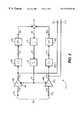
- FIG. 5is a block diagram of a combined amplitude and phase balancing system in accordance with the present invention.
- FIG. 2An embodiment showing the amplitude balancing system 17 of the present invention is shown in FIG. 2 where two bi-phase modulated signals 19 are input 21 I, 21 Q.
- Quantizingis the process of measuring the intensity of a signal in each sample and assigning a digital number to that measured value. Each time the sampling circuit samples the signal, it measures the intensity of the varying analog signal at that discrete moment in time.
- the input 23 I, 23 Q data streamsrepresent the discrete samples of data assembled into finite words each having a plurality of bits. The number of bits that define each word determine the total quantization of each sample or symbol. For example, six-bit quantization:
- Each signal 23 I, 23 Q component, I and Qis coupled to an input of an amplifier 25 I, 25 Q which has an adjustable gain.
- the output 27 I, 27 Q of the amplifiers 25 I, 25 Qare coupled to an absolute value processor 29 I, 29 Q to obtain the relative magnitudes of each incoming symbol 23 I, 23 Q.
- the output 31 I, 31 Q of the absolute value processors 29 I, 29 Qare coupled to inputs of respective low pass filters 33 I, 33 Q.
- the low pass filters 33 I, 33 Qtime-average the received component symbols 23 I, 23 Q, giving additional weight to recent samples and decreasing weight to previous samples.
- IIRinfinite impulse response
- filters 33 I, 33 Q with one poleare used, however, other types of filters or different order IIR filters can also be used without deviating from the principle of the invention.
- the low pass filter outputs 35 I, 35 Qpresent averaged estimates of the sample amplitudes output from the absolute value processors 29 I, 29 Q.
- a summer 37obtains the difference from the outputs 35 I, 35 Q of the low pass filters 33 I, 33 Q producing an error reference signal 39 . If the I and Q components of an input signal 23 I, 23 Q are orthogonal to each other, the error reference signal 39 will have zero magnitude, indicating a balanced symbol. If the error reference signal 39 produces a value other than zero, the symbols are not amplitude balanced.
- a non-zero-value error reference signal 39becomes an error correction value.
- the reference signal 39is coupled to an input of a hard limiter processor 41 .
- the hard limiter 41outputs a signal 43 smaller in magnitude, either positive or negative, in dependence upon the error reference signal 39 .
- the hard limiter processor 41clips the error reference signal 39 magnitude thereby making the sign of the error reference signal 39 a correction factor. This is done for simplifying the implementation, the hard limiter is not essential to the invention.
- the output 43 of the hard limiter processor 41is coupled to a leaky integrator which is an accumulator 45 .
- the accumulator 45adds the present value input with an accumulated value from previous input values and outputs 47 a sum. Since the accumulator 45 has a finite bit width, over time, the accumulated value will self-limit in magnitude and plateau if errors persist and are great.
- the accumulated plurality of error reference signals 39 in the internal accumulator of the accumulator 45will average to zero when the system reaches stasis.
- the output 47 from the accumulator 45is coupled to a gain input 49 I, 49 Q on each adjustable gain amplifier 25 I, 25 Q.
- the amplifiers 251 , 25 Qbalance the amplitudes of the received I and Q symbols 23 I, 23 Q, increasing or attenuating their gains in dependence with the accumulator 45 output signal 47 .
- the reference signal 39is negative feedback to the upstream amplification stages 25 I, 25 Q.
- a positive control voltage at the gain input 49 I, 49 Qindicates a gain increase for that amplifier; a negative control voltage indicates attenuation.
- a downstream automatic gain control(AGC)(not shown) equalizes the system output 51 I, 51 Q for further signal processing (not shown).
- FIG. 3An embodiment showing the phase correction system 61 of the present invention is shown in FIG. 3 .
- Two bi-phase modulated signals 19are input 63 I, 63 Q into the system 61 .
- the input 63 I, 63 Q data streams 65 I, 65 Q for the I and Q symbolsare coupled to a first input 67 I, 67 Q of parallel summers 69 I, 69 Q.
- the output 71 I, 71 Q of each summer 69 I, 69 Qare the system output 73 I, 73 Q and feedback for the phase correction system 61 .
- Both feedback lines 71 I, 71 Qare coupled to a mixer 75 for correlation.
- the mixer 75 cross-correlated output signal 77is coupled to an integrator 79 .
- the integrator 79time-averages the cross-correlation product 77 .
- the integrator outputis coupled to a hard limiter processor 83 .
- the hard decision processor 83limits the magnitude of the integrated cross-correlation product.
- the hard decision processor 83 output 85retains sign.
- the hard limiter processor 83 output 85is coupled to an accumulator input 87 .
- the hard decision processor 83reduces implementation complexity, one skilled in this art would recognize that it is not essential.
- an accumulatorAs previously discussed, the function of an accumulator is to accumulate, over-time, the present input value with previous inputs. The sum is output as a correction signal.
- the correction signal 89is coupled to a first input 91 I of a variable gain amplifier 93 I coupling the Q input 65 Q with the I input 63 I.
- the correction signal 89also is coupled to a first input 91 Q of a variable gain amplifier 93 Q coupling the I symbol input 65 I with the Q input 63 Q.
- the correction signal 89adjusts both amplifiers 93 I, 93 Q increasing or decreasing their gain.
- the amplifier outputs 95 I, 95 Qare coupled to a second input 97 I, 97 Q of the input adders 69 I, 69 Q.
- the phase correctionis shown as a vector representation in FIG. 4 .
- the adders 69 I, 69 Qsubtract the portion of Q component 63 Q from the I component 65 I;
- the outputs 71 I and 71 Q of the adders 69 I, 69 Qbecome uncorrelated I, Q and orthogonal in signal space.
- FIG. 5An alternative embodiment combining both systems correcting amplitude 17 and phase 61 imbalance is shown in FIG. 5 .
- the system 101is a simple series connection outputting 103 I, 103 Q a symbol corrected in both amplitude and phase.
- Another combined embodiment where the amplitude balancer 17 follows the phase balancer 61is also possible.
Landscapes
- Engineering & Computer Science (AREA)
- Computer Networks & Wireless Communication (AREA)
- Signal Processing (AREA)
- Digital Transmission Methods That Use Modulated Carrier Waves (AREA)
- Variable-Direction Aerials And Aerial Arrays (AREA)
- Radar Systems Or Details Thereof (AREA)
- Superheterodyne Receivers (AREA)
- Measurement Of Velocity Or Position Using Acoustic Or Ultrasonic Waves (AREA)
- Measuring Fluid Pressure (AREA)
- Electrophonic Musical Instruments (AREA)
- Transmission And Conversion Of Sensor Element Output (AREA)
- Radio Transmission System (AREA)
Abstract
Description
1. Field of the Invention
The present invention relates generally to digital communication techniques. More specifically, the invention relates to a system and method for balancing the amplitude and phase of a received, quadrature-phase modulated signal.
2. Description of the Prior Art
One of the common methods for modulating digital signals is the use of multilevel systems or M-ary techniques. M-ary modulation techniques are natural extensions of binary modulation techniques and apply to L-level amplitude or phase shift keying. A commonly used quadriphase scheme is called quadrature phage shift keying or QPSK. Like all of the M-ary amplitude or phase schemes, its principle advantage is bandwidth reduction.
Since pulse rate fpis:
where fsis the symbol rate and M is the number of messages; with L representing the number of modulation levels, the larger L is, the smaller the pulse rate and hence, the smaller the bandwidth.
In telecommunication applications, QPSK modulates two different signals into the same bandwidth creating a two-dimensional signal space. This is accomplished by creating a composite phase modulated signal using two carriers of the same frequency but having a phase difference of 90 degrees as shown in FIG.1A. By convention, the cosine carrier is called the in-phase component I and the sine carrier is the quadrature component Q. The I component is the real component of the signal and the Q component is the imaginary component of the signal. Each of the I and Q components are bi-phase modulated. A QPSK symbol consists of at least one sample from both the in-phase I and quadrature Q signals. The symbols may represent a quantized version of an analog sample or digital data.
All phase modulated schemes must overcome the inevitable problem of phase synchronization. For proper operation of QPSK signaling, the I and Q channels should have the same gain throughout processing both received channels, keeping the I and Q channels uncorrelated. Mismatched signal gains or magnitudes between the uncorrelated I and Q channels create errors when processing. Phase differences other than 90 degrees between the signals cause spillover between the channels and similarly result in degraded performance.
Typical receivers exhibit different overall gains for the separate I and Q channels due to mismatched gains in the mixers, filters, and A/D converters caused by variations in component values due in part to temperature, manufacturing tolerances and other factors. Amplitude and phase imbalance between the I and Q channels result in the distortions shown in FIGS. 1B and 1C, decreasing overall signal-to-noise ratio (SNR).
Prior art approaches taken to avoid amplitude and phase imbalance rely upon very precise circuitry controlling each gain stage with active temperature compensation. These expensive designs require components that are manufactured with extremely low temperature coefficients and with the mixers for the I and Q channels custom matched during manufacture.
Accordingly, there exists a need for a system that balances the amplitude and phase of a QPSK signal upon reception increasing signal integrity and thereby reducing bit error rate (BER).
The present invention balances the amplitude and phase of a received QPSK signal that may have been corrupted during transmission. The output from the system is a signal corrected in both amplitude and phase. The system determines the amplitude of the I and Q channels of a received signal, compares them, and applies a correction to one or both channels correcting amplitude imbalance. For phase imbalance, the system calculates the cross-correlation of the I and Q channels which should average to zero. A correction factor is derived from the cross-correlation product and is applied to both channels, returning the phase cross-correlation to zero.
Accordingly, it is an object of the invention to provide a system which balances the amplitude of a received QPSK signal.
It is a further object of the invention to provide a system which balances the phase of a received QPSK signal.
Other objects and advantages of the system and method will become apparent to those skilled in the art after reading the detailed description of the preferred embodiment.
FIG. 1A is a plot of a QPSK symbol, balanced in both amplitude and phase.
FIG. 1B is a plot of a QPSK symbol, amplitude imbalanced.
FIG. 1C is a plot of a QPSK symbol, phase imbalanced.
FIG. 2 is a block diagram of an amplitude balancing system in accordance with the present invention.
FIG. 3 is a block diagram of a phase balancing system in accordance with the present invention.
FIG. 4 is a vector representation showing phase correction.
FIG. 5 is a block diagram of a combined amplitude and phase balancing system in accordance with the present invention.
The preferred embodiment will be described with reference to the drawing figures where like numerals represent like elements throughout.
An embodiment showing theamplitude balancing system 17 of the present invention is shown in FIG. 2 where two bi-phase modulatedsignals 19 are input21I,21Q. Quantizing is the process of measuring the intensity of a signal in each sample and assigning a digital number to that measured value. Each time the sampling circuit samples the signal, it measures the intensity of the varying analog signal at that discrete moment in time. Theinput 23I,23Q data streams represent the discrete samples of data assembled into finite words each having a plurality of bits. The number of bits that define each word determine the total quantization of each sample or symbol. For example, six-bit quantization:
with n equal to 6 would yield a resolution of 63 levels. Desired signal resolution determines n.
Eachsignal 23I,23Q component, I and Q, is coupled to an input of anamplifier 25I,25Q which has an adjustable gain. Theoutput 27I,27Q of theamplifiers 25I,25Q are coupled to anabsolute value processor 29I,29Q to obtain the relative magnitudes of eachincoming symbol 23I,23Q. Theoutput 31I,31Q of theabsolute value processors 29I,29Q are coupled to inputs of respective low pass filters33I,33Q.
The low pass filters33I,33Q time-average the receivedcomponent symbols 23I,23Q, giving additional weight to recent samples and decreasing weight to previous samples. In thepresent embodiment 17, IIR (infinite impulse response) filters33I,33Q with one pole are used, however, other types of filters or different order IIR filters can also be used without deviating from the principle of the invention. The low pass filter outputs35I,35Q present averaged estimates of the sample amplitudes output from theabsolute value processors 29I,29Q.
Asummer 37 obtains the difference from theoutputs 35I,35Q of the low pass filters33I,33Q producing anerror reference signal 39. If the I and Q components of aninput signal 23I,23Q are orthogonal to each other, theerror reference signal 39 will have zero magnitude, indicating a balanced symbol. If theerror reference signal 39 produces a value other than zero, the symbols are not amplitude balanced.
A non-zero-valueerror reference signal 39 becomes an error correction value. Thereference signal 39 is coupled to an input of ahard limiter processor 41. Thehard limiter 41 outputs asignal 43 smaller in magnitude, either positive or negative, in dependence upon theerror reference signal 39. Thehard limiter processor 41 clips theerror reference signal 39 magnitude thereby making the sign of the error reference signal39 a correction factor. This is done for simplifying the implementation, the hard limiter is not essential to the invention.
Theoutput 43 of thehard limiter processor 41 is coupled to a leaky integrator which is anaccumulator 45. Theaccumulator 45 adds the present value input with an accumulated value from previous input values and outputs47 a sum. Since theaccumulator 45 has a finite bit width, over time, the accumulated value will self-limit in magnitude and plateau if errors persist and are great. The accumulated plurality of error reference signals39 in the internal accumulator of theaccumulator 45 will average to zero when the system reaches stasis.
Theoutput 47 from theaccumulator 45 is coupled to again input 49I,49Q on eachadjustable gain amplifier 25I,25Q. Theamplifiers Q symbols 23I,23Q, increasing or attenuating their gains in dependence with theaccumulator 45output signal 47. As can be seen, thereference signal 39 is negative feedback to the upstream amplification stages25I,25Q. A positive control voltage at thegain input 49I,49Q indicates a gain increase for that amplifier; a negative control voltage indicates attenuation.
If the amplitudes of the input signals23I,23Q are not balanced, the system will adjust thevariable amplifiers 25I,25Q (attenuating one component while boosting the other) according to theaccumulator 45output signal 47 until the I and Q symbol amplitudes are within a predetermined tolerance. If the symbol gains are equal, but vary between received symbols, thesystem 17 will not effect correction. A downstream automatic gain control (AGC)(not shown) equalizes thesystem output 51I,51Q for further signal processing (not shown).
An embodiment showing thephase correction system 61 of the present invention is shown in FIG.3. Two bi-phase modulated signals19 are input63I,63Q into thesystem 61. The input63I,63Q data streams65I,65Q for the I and Q symbols are coupled to afirst input 67I,67Q ofparallel summers 69I,69Q. Theoutput summer 69I,69Q are thesystem output 73I,73Q and feedback for thephase correction system 61. Bothfeedback lines mixer 75 for correlation. Themixer 75cross-correlated output signal 77 is coupled to anintegrator 79. Theintegrator 79 time-averages thecross-correlation product 77. The integrator output is coupled to ahard limiter processor 83. Thehard decision processor 83 limits the magnitude of the integrated cross-correlation product. Thehard decision processor 83output 85 retains sign. Thehard limiter processor 83output 85 is coupled to anaccumulator input 87. Thehard decision processor 83 reduces implementation complexity, one skilled in this art would recognize that it is not essential.
As previously discussed, the function of an accumulator is to accumulate, over-time, the present input value with previous inputs. The sum is output as a correction signal.
Thecorrection signal 89 is coupled to a first input91I of a variable gain amplifier93I coupling theQ input 65Q with the I input63I. Thecorrection signal 89 also is coupled to afirst input 91Q of avariable gain amplifier 93Q coupling the I symbol input65I with the Q input63Q.
Thecorrection signal 89 adjusts bothamplifiers 93I,93Q increasing or decreasing their gain. The amplifier outputs95I,95Q are coupled to asecond input 97I,97Q of theinput adders 69I,69Q.
The phase correction is shown as a vector representation in FIG.4. Theadders 69I,69Q subtract the portion of Q component63Q from the I component65I;
where rΔ cross correlation,
and the portion of I component63I from theQ component 65Q;
Q=y−xr, Equation 5
where rΔ cross correlation,
in order to remove the cross correlation contribution from each. Once the parts of the signals that result in the cross correlation are removed, theoutputs adders 69I,69Q become uncorrelated I, Q and orthogonal in signal space.
An alternative embodiment combining bothsystems correcting amplitude 17 andphase 61 imbalance is shown in FIG.5. Thesystem 101 is a simple series connection outputting103I,103Q a symbol corrected in both amplitude and phase. Another combined embodiment where theamplitude balancer 17 follows thephase balancer 61 is also possible.
While specific embodiments of the present invention have been shown and described, many modifications and variations could be made by one skilled in the art without departing from the spirit and scope of the invention. The above description serves to illustrate and not limit the particular form in any way.
Claims (10)
1. A signal balancer for use in a quadrature phase shift keying system comprising:
I and Q signal inputs, each said input coupled to first I and Q adjustable gain amplifiers, each said first amplifier having an output, said first I and Q amplifier outputs coupled to respective second I and Q adjustable gain amplifiers, each said second amplifier having an output;
means for controlling each of said first I and Q amplifier gains including:
I magnitude determining means and Q magnitude determining means coupled to said respective first I and Q amplifier outputs and to a magnitude comparator means; and
said magnitude comparator means generating a gain correction signal for both of said first I and Q amplifiers,
I and Q adders, each of said adders having a first adder input coupled to its respective first I and Q amplifier output, a second adder input coupled to said output of the different second amplifier, and a mixer output; and
means for controlling each of said second I and Q amplifier gains including an I and Q cross correlation means coupled to said I and Q mixer outputs generating a cross correlation product; whereby, said I and Q adders output amplitude and phase balanced I and Q signals.
2. The signal balancer according toclaim 1 further comprising:
respective I and Q low pass filters coupled between said I and Q magnitude determining means and said comparator means;
a hard limiter coupled to said gain correction signal and having an output;
said hard limiter output coupled to a time delay, said time delay having an output;and
said time delay coupled to said first I and Q amplifiers for controlling gain.
3. The signal balancer according toclaim 2 further comprising:
an integrator coupled to said cross correlation product and having an output;
said integrator output coupled to a hard limiter, said hard
said hard limiter output coupled to an accumulator, said accumulator having an output; and
said accumulator coupled to said second I and Q amplifiers for controlling gain.
4. A signal balancer for use in a quadrature phase shift keying system comprising:
I and Q signal inputs, each said input coupled to first I and Q adjustable gain amplifiers, each said first amplifier having an output;
I and Q mixers, each of said mixers having a first mixer input coupled to its respective signal I and Q input and a second mixer input coupled to said output of the different first amplifier and a mixer output;
means for controlling each of said first I and Q amplifier gains including:
an I and Q cross correlation means coupled to said I and Q mixer outputs generating a cross correlation product;
said cross correlation product coupled to said first I and Q amplifiers to control said first amplifier gains; and
said I and Q mixers output phase balanced I and Q signals.
5. The signal balancer according toclaim 4 further comprising:
said first I and Q amplifier outputs coupled to respective signal second I and Q adjustable gain amplifiers, each said second amplifier having an output;
means for controlling each of said second I and Q amplifier gains including:
I magnitude determining means and Q magnitude determining means coupled to said respective second I and Q amplifier outputs and magnitude comparator means;
said magnitude comparator means generating a gain correction signal for both of said second I and Q amplifiers; and
said second I and Q amplifiers output amplitude and phase balanced I and Q signals.
6. The signal balancer according toclaim 5 further comprising:
an integrator coupled to said cross correlation product and having an output;
said integrator output coupled to a hard limiter, said hard limiter having an output;
said hard limiter output coupled to an accumulator, said accumulator having an output; and
said accumulator coupled to said first I and Q amplifiers for controlling gain.
7. The signal balancer according toclaim 6 further comprising:
respective I and Q low pass filters coupled between said I and Q magnitude determining means and said comparator means;
a hard limiter coupled to said gain correction signal and having an output;
said hard limiter output coupled to a time delay, said time delay having an output; and
said time delay coupled to said first I and Q amplifiers for controlling gain.
8. A method of balancing a quadrature phase shift keyed signal where the signal includes I and Q components, the method comprising the steps of:
a) comparing the magnitude of the I component with the magnitude of the Q component;
b) generating a correction signal for both the I and Q component;
c) adjusting the gain of the I and Q components in dependence upon said correction signal producing an amplitude balanced signal;
d) cross correlating the I and Q signal components of said amplitude balanced signal;
e) deriving a cross correlation product;
f) adjusting the gain of each I and Q signal component in accordance with said cross correlation product;
g) adding one component with the adjusted gain of the different component producing an amplitude and phase balanced signal; and
repeating steps a-g.
9. A method of balancing a quadrature phase shift keyed signal where the signal includes I and Q components, the method comprising the steps of:
a) cross correlating the I and Q signal components;
b) deriving a cross correlation product;
c) adjusting the gain of each I and Q signal component in accordance with said cross correlation product;
d) adding one component with the adjusted gain of the different component producing a phase balanced signal; and
repeating steps a-d.
10. The method of balancing a quadrature phase shift keyed signal according to claim 11 further comprising the steps of:
e) comparing said phase balanced signal I magnitude component with the Q magnitude component;
f) generating a correction signal for both the I and Q component;
g) adjusting the gain of the I and0 components in dependence upon said correction signal producing a phase and amplitude balanced signal; and
repeating steps e-g.
Priority Applications (25)
| Application Number | Priority Date | Filing Date | Title |
|---|---|---|---|
| US09/233,791US6377620B1 (en) | 1999-01-19 | 1999-01-19 | Balancing amplitude and phase |
| AT99968466TATE281730T1 (en) | 1999-01-19 | 1999-12-07 | CORRECTION OF AMPLITUDE AND PHASE INEQUALITY IN PSK RECEIVER |
| ES99968466TES2232204T3 (en) | 1999-01-19 | 1999-12-07 | CORRECTION OF THE IMPROVEMENT OF AMPLITUDE AND PHASE IN PSK RECEIVERS. |
| CNB99814861XACN1142667C (en) | 1999-01-19 | 1999-12-07 | Correction of amplitude and phase imbalance in a phase shift keying receiver |
| EP04013363AEP1458158B9 (en) | 1999-01-19 | 1999-12-07 | Correction of amplitude and phase imbalance in PSK receivers |
| CA2671999ACA2671999C (en) | 1999-01-19 | 1999-12-07 | Correction of amplitude and phase imbalance in psk receivers |
| JP2000595470AJP4140943B2 (en) | 1999-01-19 | 1999-12-07 | Correction of amplitude and phase imbalance in phase shift keying receivers. |
| PCT/US1999/029002WO2000044143A1 (en) | 1999-01-19 | 1999-12-07 | Correction of amplitude and phase imbalance in psk receivers |
| CA002351761ACA2351761C (en) | 1999-01-19 | 1999-12-07 | Correction of amplitude and phase imbalance in psk receivers |
| AT04013363TATE503330T1 (en) | 1999-01-19 | 1999-12-07 | CORRECTION OF AMPLITUDE AND PHASE INEQUALITY IN PSK RECEIVER |
| DE69921693TDE69921693T2 (en) | 1999-01-19 | 1999-12-07 | CORRECTION OF AMPLITUDE AND PHASING EQUATIONS IN PSK RECEIVERS |
| CA002505751ACA2505751C (en) | 1999-01-19 | 1999-12-07 | Correction of amplitude and phase imbalance in psk receivers |
| AU25882/00AAU2588200A (en) | 1999-01-19 | 1999-12-07 | Correction of amplitude and phase imbalance in psk receivers |
| DE69943301TDE69943301D1 (en) | 1999-01-19 | 1999-12-07 | Correction of amplitude and phase inequalities in PSK receivers |
| CNB2003101012544ACN100508508C (en) | 1999-01-19 | 1999-12-07 | Correction Method of Amplitude and Phase Unbalance and Corresponding Signal Balancer in Phase Shift Keying Receiver |
| KR10-2001-7008514AKR100403751B1 (en) | 1999-01-19 | 1999-12-07 | Correction of amplitude and phase imbalance in psk receivers |
| EP99968466AEP1145517B1 (en) | 1999-01-19 | 1999-12-07 | Correction of amplitude and phase imbalance in psk receivers |
| HK02101693.6AHK1040583B (en) | 1999-01-19 | 1999-12-07 | Correction of amplitude and phase imbalance in psk receivers |
| US10/122,992US6895045B2 (en) | 1999-01-19 | 2002-04-15 | Balancing amplitude and phase |
| HK04108831.2AHK1066121B (en) | 1999-01-19 | 2004-11-10 | Method of correction of amplitude and phase imbalance in psk receivers and cross-correlation signal balancer |
| US11/126,825US7477687B2 (en) | 1999-01-19 | 2005-05-11 | Balancing amplitude and phase |
| JP2005316066AJP4343166B2 (en) | 1999-01-19 | 2005-10-31 | Correction of amplitude and phase imbalance in phase shift keying receivers. |
| JP2007188695AJP4606441B2 (en) | 1999-01-19 | 2007-07-19 | Phase shift keying receiver and method for correcting amplitude and phase imbalance |
| US12/352,303US8792545B2 (en) | 1999-01-19 | 2009-01-12 | Balancing amplitude and phase |
| JP2010120543AJP4802288B2 (en) | 1999-01-19 | 2010-05-26 | Phase shift keying receiver and method for correcting amplitude and phase imbalance |
Applications Claiming Priority (1)
| Application Number | Priority Date | Filing Date | Title |
|---|---|---|---|
| US09/233,791US6377620B1 (en) | 1999-01-19 | 1999-01-19 | Balancing amplitude and phase |
Related Child Applications (1)
| Application Number | Title | Priority Date | Filing Date |
|---|---|---|---|
| US10/122,992ContinuationUS6895045B2 (en) | 1999-01-19 | 2002-04-15 | Balancing amplitude and phase |
Publications (1)
| Publication Number | Publication Date |
|---|---|
| US6377620B1true US6377620B1 (en) | 2002-04-23 |
Family
ID=22878712
Family Applications (3)
| Application Number | Title | Priority Date | Filing Date |
|---|---|---|---|
| US09/233,791Expired - LifetimeUS6377620B1 (en) | 1999-01-19 | 1999-01-19 | Balancing amplitude and phase |
| US10/122,992Expired - Fee RelatedUS6895045B2 (en) | 1999-01-19 | 2002-04-15 | Balancing amplitude and phase |
| US12/352,303Expired - Fee RelatedUS8792545B2 (en) | 1999-01-19 | 2009-01-12 | Balancing amplitude and phase |
Family Applications After (2)
| Application Number | Title | Priority Date | Filing Date |
|---|---|---|---|
| US10/122,992Expired - Fee RelatedUS6895045B2 (en) | 1999-01-19 | 2002-04-15 | Balancing amplitude and phase |
| US12/352,303Expired - Fee RelatedUS8792545B2 (en) | 1999-01-19 | 2009-01-12 | Balancing amplitude and phase |
Country Status (12)
| Country | Link |
|---|---|
| US (3) | US6377620B1 (en) |
| EP (2) | EP1458158B9 (en) |
| JP (4) | JP4140943B2 (en) |
| KR (1) | KR100403751B1 (en) |
| CN (1) | CN1142667C (en) |
| AT (2) | ATE503330T1 (en) |
| AU (1) | AU2588200A (en) |
| CA (3) | CA2351761C (en) |
| DE (2) | DE69921693T2 (en) |
| ES (1) | ES2232204T3 (en) |
| HK (1) | HK1040583B (en) |
| WO (1) | WO2000044143A1 (en) |
Cited By (25)
| Publication number | Priority date | Publication date | Assignee | Title |
|---|---|---|---|---|
| US20010022821A1 (en)* | 2000-03-15 | 2001-09-20 | Masaki Ichihara | Amplitude deviation correction circuit |
| US20020057752A1 (en)* | 2000-06-23 | 2002-05-16 | Ntt Docomo, Inc. | Receive method and receiver in communication system |
| US20020127982A1 (en)* | 2001-03-07 | 2002-09-12 | Nokia Mobile Phones Ltd | Mobile station receiver operable for both single and multi-carrier reception |
| US20030012305A1 (en)* | 2001-06-29 | 2003-01-16 | Nokia Corporation | Adjusting a receiver |
| US20030134604A1 (en)* | 2000-07-28 | 2003-07-17 | Bertram Gunzelmann | Determination of a differential offset in a radio device and radio device |
| US20040082300A1 (en)* | 2002-08-02 | 2004-04-29 | Hans-Otto Scheck | Digital imbalance correction method and device |
| US20040146121A1 (en)* | 2003-01-24 | 2004-07-29 | Brown James E. C. | Automatic burst mode I/Q gain and I/Q phase calibration using packet based-fixed correction coefficients |
| US20040156450A1 (en)* | 2001-06-29 | 2004-08-12 | Tommi Auranen | Iq-imbalance |
| US6792054B1 (en)* | 1999-03-30 | 2004-09-14 | Texas Instruments Incorporated | Method for reducing complex frequency down-conversion impairments |
| US6822508B2 (en)* | 2001-03-08 | 2004-11-23 | Sony Corporation | Communication device, communication method, program, and storage medium |
| US20040235443A1 (en)* | 2003-05-20 | 2004-11-25 | Broadcom Corporation | Quadrature correction method for analog television reception using direct-conversion tuners |
| US20050041754A1 (en)* | 2003-08-21 | 2005-02-24 | Kuo-Ming Wu | Method and appatatus for I/Q mismatch calibration of transmitter |
| GB2406984A (en)* | 2003-06-18 | 2005-04-13 | Motorola Inc | Method and arrangement for I-Q balancing and radio receiver incorporating same |
| US20050147190A1 (en)* | 2004-01-06 | 2005-07-07 | Takurou Nishikawa | Signal processing circuit and quadrature demodulation apparatus and method of estimating error thereof |
| US20050213691A1 (en)* | 1999-01-19 | 2005-09-29 | Interdigital Technology Corporation | Balancing amplitude and phase |
| US20050227642A1 (en)* | 2004-04-08 | 2005-10-13 | Jensen Henrik T | Hardware efficient RF transceiver I/Q imbalance compensation based upon taylor approximation |
| US20060189290A1 (en)* | 2000-09-18 | 2006-08-24 | Broadcom Corporation | Direct conversion tuner |
| US20070003179A1 (en)* | 2005-06-27 | 2007-01-04 | Yokogawa Electric Corporation | QPSK light modulator |
| US7274750B1 (en)* | 2002-09-27 | 2007-09-25 | 3Com Corporation | Gain and phase imbalance compensation for OFDM systems |
| US7570710B1 (en)* | 2004-12-15 | 2009-08-04 | Rf Magic, Inc. | In-phase and quadrature-phase signal amplitude and phase calibration |
| US20130069738A1 (en)* | 2011-09-19 | 2013-03-21 | Yih-Ming Tsuie | Imbalance compensator for correcting mismatch between in-phase branch and quadrature branch, and related imbalance compensation method and direct conversion receiving apparatus thereof |
| US8831153B2 (en) | 2012-03-19 | 2014-09-09 | Kabushiki Kaisha Toshiba | Quadrature error compensating circuit |
| US8942621B2 (en) | 2010-03-29 | 2015-01-27 | Asahi Kasei Microdevices Corporation | Phase adjustment circuit and phase adjustment method |
| US20220123975A1 (en)* | 2020-10-16 | 2022-04-21 | Analog Devices, Inc. | Quadrature error correction for radio transceivers |
| US12057987B2 (en) | 2021-11-29 | 2024-08-06 | LAPIS Technology Co., Ltd. | Correction circuit and correction method |
Families Citing this family (28)
| Publication number | Priority date | Publication date | Assignee | Title |
|---|---|---|---|---|
| US6377620B1 (en)* | 1999-01-19 | 2002-04-23 | Interdigital Technology Corporation | Balancing amplitude and phase |
| KR100414362B1 (en)* | 2001-05-29 | 2004-01-07 | 엘지전자 주식회사 | apparatus and method for I/Q error calibration in digital modulation |
| US7061994B2 (en)* | 2001-06-21 | 2006-06-13 | Flarion Technologies, Inc. | Methods and apparatus for I/Q imbalance compensation |
| US7158586B2 (en)* | 2002-05-03 | 2007-01-02 | Atheros Communications, Inc. | Systems and methods to provide wideband magnitude and phase imbalance calibration and compensation in quadrature receivers |
| US6917241B2 (en)* | 2002-05-13 | 2005-07-12 | Matsushita Electric Industrial Co., Ltd. | Amplifier circuit, transmission device, amplification method, and transmission method |
| US20040013204A1 (en)* | 2002-07-16 | 2004-01-22 | Nati Dinur | Method and apparatus to compensate imbalance of demodulator |
| JP3967226B2 (en)* | 2002-08-07 | 2007-08-29 | 三星電子株式会社 | transceiver |
| WO2004023753A1 (en)* | 2002-09-05 | 2004-03-18 | Nokia Corporation | Correction of quadrature error |
| DE10245686B3 (en)* | 2002-09-30 | 2004-06-03 | Advanced Micro Devices, Inc., Sunnyvale | Phase error corrector and method |
| TWI226154B (en)* | 2003-01-20 | 2005-01-01 | Mediatek Inc | Method and related apparatus for erasing image cross talk in a low-IF receiver |
| CN100420157C (en)* | 2003-02-19 | 2008-09-17 | 联发科技股份有限公司 | Method and related device for eliminating image interference in low intermediate frequency receiver |
| DE10332584B3 (en)* | 2003-07-17 | 2005-04-28 | Infineon Technologies Ag | Compensation of IQ phase imbalance in quadrature modulation and demodulation methods |
| US7280619B2 (en) | 2003-12-23 | 2007-10-09 | Intel Corporation | Method and apparatus for compensating I/Q imbalance in receivers |
| US7333423B2 (en)* | 2004-03-31 | 2008-02-19 | Intel Corporation | Transceiver with calibrated I and Q paths and methods for deconvolved calibration |
| GB2419483B (en)* | 2004-09-17 | 2008-12-24 | Motorola Inc | Demodulator for use in wireless communucations and receiver, method and terminal using it |
| FR2888429A1 (en)* | 2005-07-06 | 2007-01-12 | St Microelectronics Sa | CORRECTION OF MATCHING DEFECTS BETWEEN TWO I AND QWAYS |
| EP1989851A2 (en)* | 2006-02-22 | 2008-11-12 | Nxp B.V. | In phase and quadrature path imbalance compensation |
| US7653124B2 (en)* | 2006-10-03 | 2010-01-26 | Fujitsu Limited | Monitoring differential phase-shifted keying demodulation |
| CN101388729B (en)* | 2007-09-14 | 2012-05-09 | 富士通株式会社 | Phase unbalance monitoring device, amplitude unbalance monitoring device and device using them |
| JP5102738B2 (en)* | 2008-10-27 | 2012-12-19 | シャープ株式会社 | IQ mismatch correction circuit |
| US8050350B2 (en)* | 2008-12-30 | 2011-11-01 | Nxp. B.V. | Receiver I-Q balance calibration |
| US8270849B2 (en)* | 2009-03-31 | 2012-09-18 | Alcatel Lucent | Phase error correction in a coherent receiver |
| US8416895B2 (en)* | 2009-06-24 | 2013-04-09 | Broadcom Corporation | Apparatus and method for IQ imbalance calibration in a receiver |
| CN102118174A (en)* | 2009-12-30 | 2011-07-06 | 上海华虹集成电路有限责任公司 | I/Q imbalance compensation device in CMMB (China Mobile Multimedia Broadcasting) receiver and method adopting same |
| JP5361927B2 (en)* | 2011-03-14 | 2013-12-04 | 株式会社東芝 | Wireless receiver |
| CN103503396A (en)* | 2011-05-10 | 2014-01-08 | 松下电器产业株式会社 | Amplitude and orthogonality error compensation device |
| JP2015154154A (en)* | 2014-02-12 | 2015-08-24 | 国立大学法人東京工業大学 | Orthogonal modulation / demodulation method and apparatus using complementary Golay codes |
| CN108169715B (en)* | 2017-11-23 | 2021-12-10 | 北京遥感设备研究所 | Method and system for determining in-phase channel phase imbalance degree and quadrature channel phase imbalance degree |
Citations (5)
| Publication number | Priority date | Publication date | Assignee | Title |
|---|---|---|---|---|
| US4085378A (en) | 1975-06-11 | 1978-04-18 | Motorola, Inc. | QPSK demodulator |
| US5263196A (en) | 1990-11-19 | 1993-11-16 | Motorola, Inc. | Method and apparatus for compensation of imbalance in zero-if downconverters |
| US5705949A (en)* | 1996-09-13 | 1998-01-06 | U.S. Robotics Access Corp. | Compensation method for I/Q channel imbalance errors |
| WO1998032221A1 (en) | 1997-01-17 | 1998-07-23 | Ericsson Inc. | Method and apparatus for compensating for imbalances between quadrature signals |
| US5949821A (en)* | 1996-08-05 | 1999-09-07 | Motorola, Inc. | Method and apparatus for correcting phase and gain imbalance between in-phase (I) and quadrature (Q) components of a received signal based on a determination of peak amplitudes |
Family Cites Families (34)
| Publication number | Priority date | Publication date | Assignee | Title |
|---|---|---|---|---|
| US4729110A (en)* | 1984-12-24 | 1988-03-01 | General Electric Company | Correction of offset and gain errors in RF receivers |
| US4736390A (en)* | 1986-10-15 | 1988-04-05 | Itt Avionics, A Division Of Itt Corporation | Zero IF radio receiver apparatus |
| DE3784717T2 (en)* | 1987-09-03 | 1993-08-26 | Philips Nv | PHASE AND GAIN CONTROL FOR A RECEIVER WITH TWO BRANCHES. |
| JPH01317010A (en) | 1988-06-16 | 1989-12-21 | Fujitsu Ltd | automatic gain control circuit |
| US5134634A (en)* | 1989-08-31 | 1992-07-28 | Nec Corporation | Multilevel quadrature amplitude demodulator capable of compensating for a quadrature phase deviation of a carrier signal pair |
| JPH0485378A (en)* | 1990-07-27 | 1992-03-18 | Toshiba Chem Corp | Polyester imide urethane paint |
| US5105195A (en)* | 1990-12-10 | 1992-04-14 | Hughes Aircraft Company | System and method for compensation of in-phase and quadrature phase and gain imbalance |
| US5249203A (en)* | 1991-02-25 | 1993-09-28 | Rockwell International Corporation | Phase and gain error control system for use in an i/q direct conversion receiver |
| JPH04275746A (en) | 1991-03-01 | 1992-10-01 | Toshiba Corp | Orthogonal modulator |
| FR2689712B1 (en)* | 1992-04-03 | 1994-08-19 | Alcatel Telspace | Device for demodulating digital signals modulated according to a technique with alternating modulation constellations. |
| US5315620A (en)* | 1992-05-01 | 1994-05-24 | Grumman Aerospace Corporation | Arrangement for correction of synchronous demodulator quadrature phase errors |
| JPH0678006A (en) | 1992-08-27 | 1994-03-18 | Sanyo Electric Co Ltd | Quadrature modulation circuit |
| JP2636132B2 (en)* | 1993-03-09 | 1997-07-30 | 日鉱金属株式会社 | Coloring method for iron products |
| US5351016A (en)* | 1993-05-28 | 1994-09-27 | Ericsson Ge Mobile Communications Inc. | Adaptively self-correcting modulation system and method |
| US5369411A (en) | 1993-06-01 | 1994-11-29 | Westinghouse Electric Corporation | Imbalance correction of in-phase and quadrature phase return signals |
| JP3552254B2 (en) | 1993-10-25 | 2004-08-11 | ソニー株式会社 | Four-phase modulation circuit |
| US5604929A (en)* | 1995-04-21 | 1997-02-18 | Rockwell International | System for correcting quadrature gain and phase errors in a direct conversion single sideband receiver independent of the character of the modulated signal |
| JP3316723B2 (en)* | 1995-04-28 | 2002-08-19 | 三菱電機株式会社 | Compensation method for receiving apparatus, receiving apparatus, and transmitting / receiving apparatus |
| KR0166877B1 (en)* | 1995-08-28 | 1999-02-01 | 구자홍 | Qpsk phase demodulator |
| JPH09186729A (en)* | 1996-01-08 | 1997-07-15 | Hitachi Denshi Ltd | Amplitude error control method for quadrature modulator and quadrature demodulator |
| US5721756A (en)* | 1996-03-26 | 1998-02-24 | Sicom, Inc. | Digital receiver with tunable analog parameters and method therefor |
| KR20000064336A (en)* | 1996-09-06 | 2000-11-06 | 요트.게.아. 롤페즈 | Zero intermediate frequency receiver |
| JPH1093478A (en)* | 1996-09-12 | 1998-04-10 | Uniden Corp | Spread spectrum signal receiver |
| CN1069007C (en) | 1997-04-11 | 2001-07-25 | 庄睛光 | Wideband Low Noise Low Intermodulation Distortion Receiver |
| JP3097605B2 (en)* | 1997-06-06 | 2000-10-10 | 日本電気株式会社 | AGC circuit |
| US6044112A (en)* | 1997-07-03 | 2000-03-28 | Hitachi America, Ltd. | Methods and apparatus for correcting amplitude and phase imbalances in demodulators |
| JPH1198212A (en) | 1997-09-19 | 1999-04-09 | Yokogawa Electric Corp | Quadrature modulator |
| US6330290B1 (en)* | 1998-09-25 | 2001-12-11 | Lucent Technologies, Inc. | Digital I/Q imbalance compensation |
| US6118322A (en)* | 1998-11-03 | 2000-09-12 | Motorola, Inc. | Method and apparatus for reducing even order distortion in differential circuits |
| CN100508508C (en)* | 1999-01-19 | 2009-07-01 | 交互数字技术公司 | Correction Method of Amplitude and Phase Unbalance and Corresponding Signal Balancer in Phase Shift Keying Receiver |
| US6377620B1 (en)* | 1999-01-19 | 2002-04-23 | Interdigital Technology Corporation | Balancing amplitude and phase |
| US6222878B1 (en)* | 1999-09-27 | 2001-04-24 | Sicom, Inc. | Communication system with end-to-end quadrature balance control |
| JP4085378B2 (en)* | 2003-03-28 | 2008-05-14 | 東洋建設株式会社 | Bottom mud covering method |
| JP5220753B2 (en) | 2006-10-16 | 2013-06-26 | コーニンクレッカ フィリップス エレクトロニクス エヌ ヴィ | Light emitting diode lighting device |
- 1999
- 1999-01-19USUS09/233,791patent/US6377620B1/ennot_activeExpired - Lifetime
- 1999-12-07EPEP04013363Apatent/EP1458158B9/ennot_activeExpired - Lifetime
- 1999-12-07CACA002351761Apatent/CA2351761C/ennot_activeExpired - Fee Related
- 1999-12-07CACA2671999Apatent/CA2671999C/ennot_activeExpired - Fee Related
- 1999-12-07AUAU25882/00Apatent/AU2588200A/ennot_activeAbandoned
- 1999-12-07CACA002505751Apatent/CA2505751C/ennot_activeExpired - Fee Related
- 1999-12-07CNCNB99814861XApatent/CN1142667C/ennot_activeExpired - Fee Related
- 1999-12-07DEDE69921693Tpatent/DE69921693T2/ennot_activeExpired - Lifetime
- 1999-12-07DEDE69943301Tpatent/DE69943301D1/ennot_activeExpired - Lifetime
- 1999-12-07KRKR10-2001-7008514Apatent/KR100403751B1/ennot_activeExpired - Fee Related
- 1999-12-07ATAT04013363Tpatent/ATE503330T1/ennot_activeIP Right Cessation
- 1999-12-07ESES99968466Tpatent/ES2232204T3/ennot_activeExpired - Lifetime
- 1999-12-07EPEP99968466Apatent/EP1145517B1/ennot_activeExpired - Lifetime
- 1999-12-07JPJP2000595470Apatent/JP4140943B2/ennot_activeExpired - Fee Related
- 1999-12-07ATAT99968466Tpatent/ATE281730T1/ennot_activeIP Right Cessation
- 1999-12-07HKHK02101693.6Apatent/HK1040583B/ennot_activeIP Right Cessation
- 1999-12-07WOPCT/US1999/029002patent/WO2000044143A1/enactiveIP Right Grant
- 2002
- 2002-04-15USUS10/122,992patent/US6895045B2/ennot_activeExpired - Fee Related
- 2005
- 2005-10-31JPJP2005316066Apatent/JP4343166B2/ennot_activeExpired - Fee Related
- 2007
- 2007-07-19JPJP2007188695Apatent/JP4606441B2/ennot_activeExpired - Fee Related
- 2009
- 2009-01-12USUS12/352,303patent/US8792545B2/ennot_activeExpired - Fee Related
- 2010
- 2010-05-26JPJP2010120543Apatent/JP4802288B2/ennot_activeExpired - Fee Related
Patent Citations (6)
| Publication number | Priority date | Publication date | Assignee | Title |
|---|---|---|---|---|
| US4085378A (en) | 1975-06-11 | 1978-04-18 | Motorola, Inc. | QPSK demodulator |
| US5263196A (en) | 1990-11-19 | 1993-11-16 | Motorola, Inc. | Method and apparatus for compensation of imbalance in zero-if downconverters |
| US5949821A (en)* | 1996-08-05 | 1999-09-07 | Motorola, Inc. | Method and apparatus for correcting phase and gain imbalance between in-phase (I) and quadrature (Q) components of a received signal based on a determination of peak amplitudes |
| US5705949A (en)* | 1996-09-13 | 1998-01-06 | U.S. Robotics Access Corp. | Compensation method for I/Q channel imbalance errors |
| WO1998032221A1 (en) | 1997-01-17 | 1998-07-23 | Ericsson Inc. | Method and apparatus for compensating for imbalances between quadrature signals |
| US6009317A (en)* | 1997-01-17 | 1999-12-28 | Ericsson Inc. | Method and apparatus for compensating for imbalances between quadrature signals |
Non-Patent Citations (3)
| Title |
|---|
| Andrew J. Viterbi: "Noncoherent Reception" and "Quasi-optimum Noncoherent Multipath Reception for M-ary Orthogonal Modulation"; 1995; "CDMA Principles of Spread Spectrum Communication";Addison-Wesley Publishing Company; ISBN 0-201-63374-4, Sub-Chapters 4.5/4.5.1; pp. 96-105. |
| Glass: Digital I/Q Imbalance Compensation In A Low-IF Receiver; Ieee Global Telecommunications Conference, Nov. 8-12, 1998, pp. 1461-1466. |
| Hiroshi Suzuki, Hitoshi Yoshino: Affine Transformations For Compensating Linear Distortion: An Application To Linear Signaling In Mobile Radio; Electronics & Communications In Japan, Part I, vol. 75, No. 1, Jan. 1992, pp. 47-58. |
Cited By (49)
| Publication number | Priority date | Publication date | Assignee | Title |
|---|---|---|---|---|
| US7477687B2 (en)* | 1999-01-19 | 2009-01-13 | Interdigital Technology Corporation | Balancing amplitude and phase |
| US20050213691A1 (en)* | 1999-01-19 | 2005-09-29 | Interdigital Technology Corporation | Balancing amplitude and phase |
| US6792054B1 (en)* | 1999-03-30 | 2004-09-14 | Texas Instruments Incorporated | Method for reducing complex frequency down-conversion impairments |
| US7206360B2 (en)* | 2000-03-15 | 2007-04-17 | Nec Corporation | Amplitude deviation correction circuit |
| US20010022821A1 (en)* | 2000-03-15 | 2001-09-20 | Masaki Ichihara | Amplitude deviation correction circuit |
| US20020057752A1 (en)* | 2000-06-23 | 2002-05-16 | Ntt Docomo, Inc. | Receive method and receiver in communication system |
| US6987815B2 (en)* | 2000-06-23 | 2006-01-17 | Ntt Docomo, Inc. | Receive method and receiver in communication system |
| US20030134604A1 (en)* | 2000-07-28 | 2003-07-17 | Bertram Gunzelmann | Determination of a differential offset in a radio device and radio device |
| US6973295B2 (en)* | 2000-07-28 | 2005-12-06 | Infineon Technologies Ag | Determination of a differential offset in a radio device and radio device |
| US20100093295A1 (en)* | 2000-09-18 | 2010-04-15 | Broadcom Corporation | Direct conversion tuner |
| US20060189290A1 (en)* | 2000-09-18 | 2006-08-24 | Broadcom Corporation | Direct conversion tuner |
| US8467755B2 (en) | 2000-09-18 | 2013-06-18 | Broadcom Corporation | Direct conversion tuner |
| US7636558B2 (en)* | 2000-09-18 | 2009-12-22 | Broadcom Corporation | Direct conversion tuner |
| US20020127982A1 (en)* | 2001-03-07 | 2002-09-12 | Nokia Mobile Phones Ltd | Mobile station receiver operable for both single and multi-carrier reception |
| US6822508B2 (en)* | 2001-03-08 | 2004-11-23 | Sony Corporation | Communication device, communication method, program, and storage medium |
| US20040156450A1 (en)* | 2001-06-29 | 2004-08-12 | Tommi Auranen | Iq-imbalance |
| US20080212711A1 (en)* | 2001-06-29 | 2008-09-04 | Nokia Corporation | IQ-Imbalance |
| US20030012305A1 (en)* | 2001-06-29 | 2003-01-16 | Nokia Corporation | Adjusting a receiver |
| US7336730B2 (en)* | 2001-06-29 | 2008-02-26 | Nokia Corporation | IQ-imbalance |
| US7233629B2 (en)* | 2001-06-29 | 2007-06-19 | Nokia Corporation | Adjusting a receiver |
| US20040082300A1 (en)* | 2002-08-02 | 2004-04-29 | Hans-Otto Scheck | Digital imbalance correction method and device |
| US7376170B2 (en)* | 2002-08-02 | 2008-05-20 | Nokia Corporation | Digital imbalance correction method and device in a receiver for multi-carrier applications |
| US7274750B1 (en)* | 2002-09-27 | 2007-09-25 | 3Com Corporation | Gain and phase imbalance compensation for OFDM systems |
| US6950480B2 (en)* | 2003-01-24 | 2005-09-27 | Texas Instruments Incorporated | Receiver having automatic burst mode I/Q gain and phase balance |
| US20040146120A1 (en)* | 2003-01-24 | 2004-07-29 | Brown James E. C. | Receiver having automatic burst mode I/Q gain and phase balance |
| US20040146121A1 (en)* | 2003-01-24 | 2004-07-29 | Brown James E. C. | Automatic burst mode I/Q gain and I/Q phase calibration using packet based-fixed correction coefficients |
| US6940930B2 (en)* | 2003-01-24 | 2005-09-06 | Texas Instruments Incorporated | Automatic burst mode I/Q gain and I/Q phase calibration using packet based-fixed correction coefficients |
| US20090040393A1 (en)* | 2003-05-20 | 2009-02-12 | Broadcom Corporation | Quadrature correction method for analog television reception using direct-conversion tuners |
| US7412222B2 (en)* | 2003-05-20 | 2008-08-12 | Broadcom Corporation | Quadrature correction method for analog television reception using direct-conversion tuners |
| US20040235443A1 (en)* | 2003-05-20 | 2004-11-25 | Broadcom Corporation | Quadrature correction method for analog television reception using direct-conversion tuners |
| US8165554B2 (en)* | 2003-05-20 | 2012-04-24 | Gomez Ramon A | Quadrature correction method for analog television reception using direct-conversion tuners |
| GB2406984A (en)* | 2003-06-18 | 2005-04-13 | Motorola Inc | Method and arrangement for I-Q balancing and radio receiver incorporating same |
| GB2406984B (en)* | 2003-06-18 | 2005-12-21 | Motorola Inc | Method and arrangement for I-Q balancing and radio receiver incorporating same |
| US7298793B2 (en)* | 2003-08-21 | 2007-11-20 | Mediatek Inc. | Method and apparatus for I/Q mismatch calibration of transmitter |
| US20050041754A1 (en)* | 2003-08-21 | 2005-02-24 | Kuo-Ming Wu | Method and appatatus for I/Q mismatch calibration of transmitter |
| US7356103B2 (en)* | 2004-01-06 | 2008-04-08 | Fujitsu Limited | Signal processing circuit and quadrature demodulation apparatus and method of estimating error thereof |
| US20050147190A1 (en)* | 2004-01-06 | 2005-07-07 | Takurou Nishikawa | Signal processing circuit and quadrature demodulation apparatus and method of estimating error thereof |
| US7349677B2 (en)* | 2004-04-08 | 2008-03-25 | Broadcom Corporation | Hardware efficient RF transceiver I/Q imbalance compensation based upon taylor approximation |
| US20050227642A1 (en)* | 2004-04-08 | 2005-10-13 | Jensen Henrik T | Hardware efficient RF transceiver I/Q imbalance compensation based upon taylor approximation |
| US7570710B1 (en)* | 2004-12-15 | 2009-08-04 | Rf Magic, Inc. | In-phase and quadrature-phase signal amplitude and phase calibration |
| US7366362B2 (en)* | 2005-06-27 | 2008-04-29 | Yokogawa Electric Corporation | QPSK light modulator |
| US20070003179A1 (en)* | 2005-06-27 | 2007-01-04 | Yokogawa Electric Corporation | QPSK light modulator |
| US8942621B2 (en) | 2010-03-29 | 2015-01-27 | Asahi Kasei Microdevices Corporation | Phase adjustment circuit and phase adjustment method |
| US20130069738A1 (en)* | 2011-09-19 | 2013-03-21 | Yih-Ming Tsuie | Imbalance compensator for correcting mismatch between in-phase branch and quadrature branch, and related imbalance compensation method and direct conversion receiving apparatus thereof |
| US8670738B2 (en)* | 2011-09-19 | 2014-03-11 | Mediatek Inc. | Imbalance compensator for correcting mismatch between in-phase branch and quadrature branch, and related imbalance compensation method and direct conversion receiving apparatus thereof |
| US8831153B2 (en) | 2012-03-19 | 2014-09-09 | Kabushiki Kaisha Toshiba | Quadrature error compensating circuit |
| US20220123975A1 (en)* | 2020-10-16 | 2022-04-21 | Analog Devices, Inc. | Quadrature error correction for radio transceivers |
| US11374803B2 (en)* | 2020-10-16 | 2022-06-28 | Analog Devices, Inc. | Quadrature error correction for radio transceivers |
| US12057987B2 (en) | 2021-11-29 | 2024-08-06 | LAPIS Technology Co., Ltd. | Correction circuit and correction method |
Also Published As
Similar Documents
| Publication | Publication Date | Title |
|---|---|---|
| US6377620B1 (en) | Balancing amplitude and phase | |
| US7061994B2 (en) | Methods and apparatus for I/Q imbalance compensation | |
| US4085378A (en) | QPSK demodulator | |
| US5598436A (en) | Digital transmission system with predistortion | |
| AU638362B2 (en) | Digital radio receiver having amplitude limiter and logarithmic detector | |
| US7187725B2 (en) | Method and apparatus for compensating I/Q imbalance by using variable loop gain in quadrature demodulator | |
| US7477687B2 (en) | Balancing amplitude and phase | |
| US20050078776A1 (en) | Apparatus and method for compensating I/Q imbalance based on gain-controlled reference channel in orthogonal frequency division multiplex | |
| MXPA01006193A (en) | Correction of amplitude and phase imbalance in psk receivers | |
| CN116546613B (en) | Method, device, equipment and medium for determining wireless local area network I/Q time imbalance | |
| HK1066121B (en) | Method of correction of amplitude and phase imbalance in psk receivers and cross-correlation signal balancer |
Legal Events
| Date | Code | Title | Description |
|---|---|---|---|
| AS | Assignment | Owner name:INTERDIGITAL TECHNOLOGY CORPORATION, DELAWARE Free format text:ASSIGNMENT OF ASSIGNORS INTEREST;ASSIGNORS:OZLUTURK, FATIH M.;DICK, STEPHEN G.;KAZAKEVICH, LEONID;REEL/FRAME:009716/0759;SIGNING DATES FROM 19981228 TO 19990107 | |
| STCF | Information on status: patent grant | Free format text:PATENTED CASE | |
| CC | Certificate of correction | ||
| CC | Certificate of correction | ||
| FPAY | Fee payment | Year of fee payment:4 | |
| FPAY | Fee payment | Year of fee payment:8 | |
| FPAY | Fee payment | Year of fee payment:12 |