US6377189B1 - Oil well servicing system - Google Patents
Oil well servicing systemDownload PDFInfo
- Publication number
- US6377189B1 US6377189B1US09/281,864US28186499AUS6377189B1US 6377189 B1US6377189 B1US 6377189B1US 28186499 AUS28186499 AUS 28186499AUS 6377189 B1US6377189 B1US 6377189B1
- Authority
- US
- United States
- Prior art keywords
- well site
- well
- digital
- feedback signal
- service operation
- Prior art date
- Legal status (The legal status is an assumption and is not a legal conclusion. Google has not performed a legal analysis and makes no representation as to the accuracy of the status listed.)
- Expired - Lifetime
Links
- 239000003129oil wellSubstances0.000titledescription6
- 238000012544monitoring processMethods0.000claimsabstractdescription5
- 238000004891communicationMethods0.000claimsdescription18
- 238000013500data storageMethods0.000claimsdescription11
- 230000006870functionEffects0.000claimsdescription7
- 230000004044responseEffects0.000claimsdescription5
- 238000000034methodMethods0.000description8
- 239000000126substanceSubstances0.000description8
- 239000004568cementSubstances0.000description6
- 239000012530fluidSubstances0.000description6
- 238000005086pumpingMethods0.000description5
- 238000011282treatmentMethods0.000description4
- 210000004907glandAnatomy0.000description3
- XLYOFNOQVPJJNP-UHFFFAOYSA-NwaterSubstancesOXLYOFNOQVPJJNP-UHFFFAOYSA-N0.000description3
- 238000012423maintenanceMethods0.000description2
- 239000003921oilSubstances0.000description2
- 239000003208petroleumSubstances0.000description2
- 239000007789gasSubstances0.000description1
- 239000007943implantSubstances0.000description1
- 238000012986modificationMethods0.000description1
- 230000004048modificationEffects0.000description1
- -1steamSubstances0.000description1
- 230000000007visual effectEffects0.000description1
Images


Classifications
- E—FIXED CONSTRUCTIONS
- E21—EARTH OR ROCK DRILLING; MINING
- E21B—EARTH OR ROCK DRILLING; OBTAINING OIL, GAS, WATER, SOLUBLE OR MELTABLE MATERIALS OR A SLURRY OF MINERALS FROM WELLS
- E21B41/00—Equipment or details not covered by groups E21B15/00 - E21B40/00
- E—FIXED CONSTRUCTIONS
- E21—EARTH OR ROCK DRILLING; MINING
- E21B—EARTH OR ROCK DRILLING; OBTAINING OIL, GAS, WATER, SOLUBLE OR MELTABLE MATERIALS OR A SLURRY OF MINERALS FROM WELLS
- E21B47/00—Survey of boreholes or wells
Definitions
- the inventiongenerally pertains to oil wells and more specifically to a system for servicing oil wells.
- Such service operationsmay include replacing worn parts such as a pump, sucker rods, inner tubing, and packer glands; pumping chemical treatments or hot oil down into the well bore; and pouring cement into the well bore to partially close off a portion of the well (or to shut it down entirely). Since wells are often miles apart from each other, the maintenance or service operations are usually performed by a mobile unit or service vehicle having special onboard servicing equipment suited to perform the work.
- service vehiclesinclude a chemical tank truck or trailer, a cement truck or trailer, a hot-oiler tank truck or trailer, and a portable work-over service rig having a hoist to remove and install well components (e.g., sucker rods, tubing, etc.).
- well componentse.g., sucker rods, tubing, etc.
- Service vehiclesare often owned by a contractor that the well owner hires to service the wells. Typically, the contractor performs the work and invoices the owner. For many service operations, it is difficult for the owner to confirm exactly what work was actually done or how well it was done, without actually witnessing the work while it is in progress. In the case of pumping a chemical treatment down into a well bore, it is virtually impossible to confirm how much chemical was dispensed after the fact. Other examples would include not being able to confirm the temperature or quantity of a hot oil treatment, the quantity and position of replaced sucker rods or tubing, and the torque used in tightening sucker rods or tubing. There are numerous other possible service operations that are difficult to confirm after the work has been reported as having been completed.
- a second objectis to provide a secure record that can be relied upon at a later date to resolve a maintenance problem, resolve a question of theft, or determine the cause of an accident that may have occurred at the well site.
- a third objectis to provide a well servicing system for use on a mobile well servicing vehicle.
- a fourth objectis to provide a durable well identification device that stores a digital well identification value without having to maintain the device with a source of electrical power.
- a fifth objectis to provide a well servicing system that minimizes a temptation for others to improperly alter data.
- a sixth objectis to provide a well servicing system that lends itself well to a wide variety of processes.
- a seventh objectis to eliminate much of the paper shuffling that is often associated with an invoice created by several people manually comparing handwritten work reports to purchase orders, contracts, and a myriad of other documents.
- a novel well servicing systemthat includes a mobile transducer that senses a parameter of a service operation performed at a plurality of well sites, and includes a memory that stores information provided by the transducer with reference to a well site identifier at each well site to associate the information with the proper well site at which the service operation was performed.
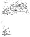
- FIG. 1is a schematic view of a well servicing system, according to one embodiment of the invention, showing a service vehicle at a first well site.
- FIG. 2is another schematic view of the system of FIG. 1, but showing the service vehicle traveling between two well sites.
- FIG. 3is the same as FIG. 1, but showing the service vehicle at a second well site.
- FIG. 4is a schematic view of another embodiment.
- FIG. 5is a schematic view of another embodiment.
- FIG. 6is a schematic view of another embodiment.
- FIG. 7is a schematic view of another embodiment.
- FIGS. 1-3A first oil well 10 separated several miles from a second oil well 12 are shown in FIGS. 1-3 being serviced by a service vehicle 14 .
- Vehicle 14is shown servicing well 10 in FIG. 1, servicing well 12 in FIG. 3, and traveling along a road between wells 10 and 12 in FIG. 2 .
- Wells 10 and 12each includes a pivoting beam 16 that raises and lowers a string of sucker rods 18 to operate a pump submerged deep within a well bore 20 .
- service operationsinclude, but are not limited to, replacing worn parts such as a pump, sucker rods, inner tubing, and packer glands; pumping chemical treatments or hot oil down into the well bore; and pouring cement into the well bore to partially close off a portion of the well (or to shut it down entirely).
- Such servicesare usually performed by an appropriately equipped service vehicle of which some examples would include, but not be limited to, a chemical tank truck or trailer, a cement truck or trailer, a hot-oiler tank truck or trailer, and a portable work-over service rig having a hoist to remove and install well components (e.g., sucker rods, tubing, etc.). All of these examples of service vehicles and more are schematically/generically represented by vehicle 14 of FIGS. 1-3.
- vehicle 14includes a pump 22 that pumps a fluid (e.g., hot oil, cement, or chemical) from a tank 24 , through a hose 26 and down into well bore 20 .
- the pumping process and a variety of other service operationscan be monitored by several transducers that sense various process parameters.
- the term, “parameter” used in relation to performing a service operation or process on a wellrepresents any detectable feature that reflects at least some condition or status of the process.
- transducer 28monitors the flow rate
- a second transducer 30monitors the pressure
- a third transducer 32monitors the temperature
- a fourth transducer 34(removably attached to the well head) monitors any one of a variety of other parameters, such as fluid acidity or concentration.
- transducer 34could count the number of parts being removed or installed to monitor inventory.
- a fifth transducer 36could monitor the force or weight being applied to vehicle 14 (e.g., a portable work-over service rig having a hoist to remove and install well components).
- Transducer 36 in conjunction with a sixth transducer 38 monitoring a hoist engine speedcould monitor the force and horsepower required to pull a rod 18 from well bore 20 .
- transducers 28 , 30 , 32 , 34 , 36 and 38provide analog feedback signals 40 (i.e., 40 a , 40 b , 40 c , 40 d , 40 e and 40 f respectively) that an analog to digital converter 42 periodically converts to digital feedback values 44 (i.e., 44 a , 44 b , 44 c , 44 d , 44 e and 44 f respectively).
- Analog feedback signalstypically take the form of voltage (e.g., 0-5 VDC) or current (e.g., 4-20 mA), however other forms of analog feedback could also be used.
- digital feedback valueas used throughout this disclosure is equivalent and interchangeable with the term “digital feedback signal” both of which encompass a quantity that if varied, varies in discrete increments.
- Digital feedback values and digital feedback signalscan take a wide variety of forms including, but not limited to, binary voltage, alphanumeric data (e.g., whole numbers, decimals, letters, and combinations thereof, etc.), bar code and magnetic recording. It should be appreciated by those skilled in the art, that incorporating an analog to digital converter within the transducer itself is well within the scope of the invention.
- a conventional microprocessor circuit 46(well known to those skilled in the art) periodically conveys digital feedback values 44 to a memory 48 where the values are stored.
- Memory 48represents any data storage device and its ancillary elements that facilitate its use.
- Memory 48is schematically illustrated to represent the wide variety of forms that it can assume, which include, but are not limited to, a hard drive of a computer; a floppy disc; a CD (compact disk); ZIP drive/cartridge, an electronic chip such as RAM, EPROM, or EEPROM and variations thereof; and magnetic tape.
- a clock 50provides a digital time stamp 52 that circuit 46 also conveys to memory 48 to provide digital feedback values 44 with a time reference.
- circuit 46 , clock 50 and memory 48can be provided by any one of a wide variety circuits, in one embodiment, devices 46 , 50 and 48 comprise a computer. In another embodiment, however, devices 46 , 50 and 48 include a “POCKET LOGGER” by Pace Scientific, Inc. of Charlotte, N.C.
- each well 10 and 12includes a well identifier 54 (e.g., 54 a , 54 b , 54 c and 54 d ).
- well identifierused herein and below represents any value or feature that can be referenced to distinguish one well from another.
- Some examples of well identifier 54include, but are not limited to, a bar code label (as commonly used on retail merchandise, e.g., labels 54 a and 54 b ), data stored on a magnetic or electromagnetic strip (similar to a common credit card or some building access security badges, e.g., item 54 c ), and data stored on an integrated circuit chip (similar to an electromagnetic implant used for animal identification).
- a well identifierexamples include data stored on a memory 54 d such as a hard drive of a computer; a floppy disc; a CD (compact disk); ZIP drive/cartridge, an electronic chip such as RAM, EPROM, or EEPROM and variations thereof; and magnetic tape.
- a memory 54 dsuch as a hard drive of a computer; a floppy disc; a CD (compact disk); ZIP drive/cartridge, an electronic chip such as RAM, EPROM, or EEPROM and variations thereof; and magnetic tape.
- Information of well identifier 54preferably takes the form of a digital well site value 56 (e.g., 56 a , 56 b , 56 c and 56 d ).
- digital well site value 56 ais represented by a series of bars of varying width and/or pitch.
- the digital well site valueis conveyed to memory 48 by way of a communication link 58 (e.g., 58 a , 58 b , 58 c , 58 d and 58 e ).
- communication link 58 aincludes a visual scan 60 of label 54 a by way of a conventional bar code scanner 62 and a cable 64 electrically coupled to memory 48 .
- Well site value 56 a and digital feedback values 44are stored in memory 48 in reference to each other, i.e., values 56 a and 44 can be referenced later in relation to each other, such that one knows which digital feedback values go with which well site value.
- vehicle 14drives up to well 10 , and an operator scans bar code label 54 a .
- the scanned digital well site value 56 ais conveyed to memory 48 by way of communication link 58 a .
- the operatorconnects a hose 26 to well bore 20 and sets up transducers 34 and 36 as shown. Some (or all) of the transducers may already be set up upon arrival of vehicle 14 , such as transducers 28 , 30 , 32 and 38 in this case.
- the service operation processis performed (e.g., pumping a fluid into well bore 20 through hose 26 ), while data provided by the transducers is recorded in memory 48 in the form of digital feedback values 44 .
- Clock 50can provide various time stamps 52 to indicate when vehicle 14 arrived at the site to scan label 54 a , when the service process began and stopped, when the digital feedback values 44 were sampled, and when vehicle 14 departed.
- hose 26 , scanner 62 , and transducers 34 and 36can be disconnected and/or stored for transport with vehicle 14 .
- clock 50 , transducer 38 and other transducerscould continue to feed memory 48 with data to provide a record of information such as travel time, speed, travel distance, etc., if desired.
- the setup and operationcan proceed as just described in relation to well 10 , or an entirely different service operation can be performed, depending upon the service needs of well 12 and the capabilities of service vehicle 14 .
- the scanned digital value 56 b of label 54 bwould be different than that of well 10 , so that whatever data is collected at well 12 would not be confused with the data that had been gathered and recorded at well 10 .
- FIGS. 4-7Alternate embodiments of the invention are shown in FIGS. 4-7.
- well site identifier 54 cincludes an electromagnetic element such as magnet strip 66
- communication link 58 bincludes an appropriate electromagnetic detector 68 that senses digital well site value 56 c of strip 66 .
- the overall operation of the embodiment of FIG. 4is generally the same as that of FIGS. 1-3.
- the well identifieris memory 54 d of a computer 69 .
- Memory 54 dis able to store an entered digital well site value 56 d .
- memory 54 d and memory 48are combined. Feedback from the transducers are conveyed to memory 48 by way of communication link 58 c that includes a readily disconnectable cable 70 .
- A/D converter 42is shown closely associated with vehicle 14 with cable 70 conveying digital feedback, it should be appreciated by those skilled in the art that converter 42 could optionally be closely associated with computer 69 with cable 70 conveying analog feedback instead. Either way, as vehicle 14 travels between well sites, the transducers travel with vehicle 14 , while each well site has its own resident memory 48 and 54 d
- FIG. 6The embodiment of FIG. 6 is similar to that of FIG. 5, however cable 70 is replaced by an electromagnetic communication link 58 d provided by an electromagnet transmitter 72 and an electromagnetic receiver 74 .
- transmitter 72emits a radio signal that receiver 74 receives and computer 69 interprets as an indication that a specifically identified vehicle 14 has arrived at the well site.
- computer 69provides an indication (e.g. a green light) to the operator of the vehicle that his vehicle has been recognized and that computer 69 is ready to receive transducer feedback data. The operator performs the service operation on the well, while transducer feedback is transmitted to computer 69 for storage in memory 48 .
- the datais stored with limited access (e.g., lock and key and/or a computer password, all of which are depicted by numeral 76 ) for security purposes to prevent unauthorized tampering or altering of the data. In other words, those performing the service operation are inhibited from falsifying the data collected at the well site. Later, an owner of the well or a representative thereof with sufficient security clearance can access the stored data and use the information for a variety purposes including, but not limited to automatically creating an invoice 77 specifying the amount of payment due as a function of the data collected at the well site.
- limited accesse.g., lock and key and/or a computer password, all of which are depicted by numeral 76
- an owner of the well or a representative thereof with sufficient security clearancecan access the stored data and use the information for a variety purposes including, but not limited to automatically creating an invoice 77 specifying the amount of payment due as a function of the data collected at the well site.
- a database memory 81(e.g., a hard drive of a computer; a floppy disc; a CD (compact disk); ZIP drive/cartridge, an electronic chip such as RAM, EPROM, or EEPROM and variations thereof; and magnetic tape) stores data (i.e., plurality of digital feedback signals in reference to well site values) that has been collected over a period of days or years to provide a record 83 that serves as a history of the work performed at various wells.
- datai.e., plurality of digital feedback signals in reference to well site values
- FIG. 7is similar to those of FIGS. 5 and 6; however, communication link 58 e includes physically carrying a portable data storage element 78 between vehicle 14 and the well site.
- Portable data storage element 78is schematically illustrated to represent the wide variety of forms that element 78 can assume, which include, but are not limited to a memory chip, such as RAM, EPROM, EEPROM and variations thereof; a magnetically recordable tape; a magnetically recordable disc such as a floppy disc; and a CD.
- the operation of this embodimentcan vary, but in one example, transducer feedback is stored on a floppy disc at a disc drive 80 . After the service operation is performed, the floppy disc with the transducer feedback data is then carried to computer 69 that is kept at the well site to serve as a well site identifier. Computer 69 reads and stores the transducer feedback data for later reference.
Landscapes
- Life Sciences & Earth Sciences (AREA)
- Engineering & Computer Science (AREA)
- Geology (AREA)
- Mining & Mineral Resources (AREA)
- Physics & Mathematics (AREA)
- Environmental & Geological Engineering (AREA)
- Fluid Mechanics (AREA)
- General Life Sciences & Earth Sciences (AREA)
- Geochemistry & Mineralogy (AREA)
- Geophysics (AREA)
- Arrangements For Transmission Of Measured Signals (AREA)
- Time Recorders, Dirve Recorders, Access Control (AREA)
Abstract
Description
Claims (21)
Priority Applications (2)
| Application Number | Priority Date | Filing Date | Title |
|---|---|---|---|
| US09/281,864US6377189B1 (en) | 1999-03-31 | 1999-03-31 | Oil well servicing system |
| CA002382231ACA2382231C (en) | 1999-03-31 | 2002-04-15 | Oil well servicing system |
Applications Claiming Priority (2)
| Application Number | Priority Date | Filing Date | Title |
|---|---|---|---|
| US09/281,864US6377189B1 (en) | 1999-03-31 | 1999-03-31 | Oil well servicing system |
| CA002382231ACA2382231C (en) | 1999-03-31 | 2002-04-15 | Oil well servicing system |
Publications (1)
| Publication Number | Publication Date |
|---|---|
| US6377189B1true US6377189B1 (en) | 2002-04-23 |
Family
ID=32736728
Family Applications (1)
| Application Number | Title | Priority Date | Filing Date |
|---|---|---|---|
| US09/281,864Expired - LifetimeUS6377189B1 (en) | 1999-03-31 | 1999-03-31 | Oil well servicing system |
Country Status (2)
| Country | Link |
|---|---|
| US (1) | US6377189B1 (en) |
| CA (1) | CA2382231C (en) |
Cited By (33)
| Publication number | Priority date | Publication date | Assignee | Title |
|---|---|---|---|---|
| US20030091390A1 (en)* | 2001-10-25 | 2003-05-15 | Kikuo Kaga | Cement distribution system |
| US20030196798A1 (en)* | 2001-09-05 | 2003-10-23 | Key Energy Services, Inc. | Method of monitoring service operations of a service vehicle at a well site |
| US6728638B2 (en)* | 2001-04-23 | 2004-04-27 | Key Energy Services, Inc. | Method of monitoring operations of multiple service vehicles at a well site |
| US20040188088A1 (en)* | 2003-02-14 | 2004-09-30 | Newman Frederic M. | Warning device to prevent clutch burning |
| US20040196032A1 (en)* | 2003-01-21 | 2004-10-07 | Key Energy Services, Inc. | Inventory counter for oil and gas wells |
| US20040226712A1 (en)* | 2003-05-14 | 2004-11-18 | Hood John Charles | Portable memory device for mobile workover rig |
| US6826492B2 (en)* | 2001-04-23 | 2004-11-30 | Key Energy Services, Inc. | Method of managing a well file record at a well site |
| US20050103491A1 (en)* | 2003-10-03 | 2005-05-19 | Key Energy Serivices, Inc. | Activity data capture system for a well service vehicle |
| US6985750B1 (en)* | 1999-04-27 | 2006-01-10 | Bj Services Company | Wireless network system |
| US7006009B2 (en) | 2002-04-01 | 2006-02-28 | Key Energy Services, Inc. | Servicing system for wells |
| US7004456B2 (en) | 2002-10-03 | 2006-02-28 | Key Energy Services, Inc. | Engine speed limiter for a hoist |
| US7029422B2 (en) | 2003-02-14 | 2006-04-18 | Key Energy Services, Inc. | Ergonomics safety warning device and method to prevent clutch burning |
| US20070035413A1 (en)* | 2003-04-11 | 2007-02-15 | Vesa Uitto | System for managing borehole information |
| US20070056746A1 (en)* | 2005-09-13 | 2007-03-15 | Key Energy Services, Inc. | Method and system for evaluating weight data from a service rig |
| US20070056727A1 (en)* | 2005-09-13 | 2007-03-15 | Key Energy Services, Inc. | Method and system for evaluating task completion times to data |
| US20070227225A1 (en)* | 2006-03-28 | 2007-10-04 | Newman Frederic M | Method and system for calibrating a tube scanner |
| US20080040065A1 (en)* | 2006-08-11 | 2008-02-14 | Grant James S | Diagnosis and troubleshooting for above-ground well systems |
| US20080035333A1 (en)* | 2006-03-27 | 2008-02-14 | Newman Frederic M | Method and system for scanning tubing |
| US20080035335A1 (en)* | 2006-03-27 | 2008-02-14 | Newman Frederic M | Method and system for evaluating and displaying depth data |
| US20090045973A1 (en)* | 2007-08-16 | 2009-02-19 | Rodney Paul F | Communications of downhole tools from different service providers |
| US7571054B2 (en) | 2006-03-27 | 2009-08-04 | Key Energy Services, Inc. | Method and system for interpreting tubing data |
| US20110144809A1 (en)* | 2007-05-10 | 2011-06-16 | Canrig Drilling Technology Ltd. | Well prog execution facilitation system and method |
| US20110284218A1 (en)* | 2010-05-19 | 2011-11-24 | Aleksei Aleksandrovich Chudnovsky | Method for increasing the formation oil yield during crude oil production and apparatus thereof |
| WO2014004515A1 (en)* | 2012-06-25 | 2014-01-03 | Lord Corporation | Data-logging truck control system |
| US20140214476A1 (en)* | 2013-01-31 | 2014-07-31 | Halliburton Energy Services, Inc. | Data initialization for a subterranean operation |
| US9458683B2 (en) | 2012-11-19 | 2016-10-04 | Key Energy Services, Llc | Mechanized and automated well service rig system |
| US11339612B1 (en)* | 2021-10-08 | 2022-05-24 | Frederic M Newman | Electric well service rig |
| US11401797B1 (en) | 2021-10-08 | 2022-08-02 | Frederic M Newman | Electric well service rig for ESP installations |
| US11441397B2 (en)* | 2016-05-18 | 2022-09-13 | Mti Group Pty Ltd | Apparatus and method for lining a blast hole |
| US11448050B1 (en) | 2021-10-08 | 2022-09-20 | Frederic M Newman | Universal electric well service rig |
| US11572260B1 (en) | 2022-05-03 | 2023-02-07 | Frederic M Newman | Electric well service rig with speed limiter |
| US11674365B1 (en) | 2023-02-14 | 2023-06-13 | Frederic M Newman | Battery shuttle for electric well service rigs |
| US20230417116A1 (en)* | 2020-12-15 | 2023-12-28 | Intelligent Wellhead Systems Inc. | System and method for controlling well operations |
Citations (12)
| Publication number | Priority date | Publication date | Assignee | Title |
|---|---|---|---|---|
| US4700142A (en)* | 1986-04-04 | 1987-10-13 | Vector Magnetics, Inc. | Method for determining the location of a deep-well casing by magnetic field sensing |
| US4765435A (en)* | 1985-08-06 | 1988-08-23 | Schlumberger Technology Corporation | Mobile well-logging laboratory |
| US4884847A (en)* | 1988-02-19 | 1989-12-05 | Consolidation Coal Co. | Apparatus and method for mapping entry conditions in remote mining systems |
| US5218301A (en)* | 1991-10-04 | 1993-06-08 | Vector Magnetics | Method and apparatus for determining distance for magnetic and electric field measurements |
| US5298894A (en)* | 1992-06-17 | 1994-03-29 | Badger Meter, Inc. | Utility meter transponder/antenna assembly for underground installations |
| US5438329A (en)* | 1993-06-04 | 1995-08-01 | M & Fc Holding Company, Inc. | Duplex bi-directional multi-mode remote instrument reading and telemetry system |
| US5617084A (en)* | 1993-09-10 | 1997-04-01 | Sears; Lawrence M. | Apparatus for communicating utility usage-related information from a utility usage location to a utility usage registering device |
| US6006212A (en)* | 1997-09-17 | 1999-12-21 | Itron, Inc. | Time-of-use and demand metering in conditions of power outage with a mobile node |
| US6021093A (en)* | 1997-05-14 | 2000-02-01 | Gas Research Institute | Transducer configuration having a multiple viewing position feature |
| USRE36569E (en)* | 1992-11-06 | 2000-02-15 | Vector Magnetics, Inc. | Method and apparatus for measuring distance and direction by movable magnetic field source |
| US6087965A (en)* | 1995-06-15 | 2000-07-11 | Trimble Navigation Limited | Vehicle mileage meter and a GPS position tracking system |
| US6253849B1 (en)* | 1998-04-10 | 2001-07-03 | Newman Family Partnership, Ltd. | Method of distinguishing the raising and lowering of tubing and sucker rods |
- 1999
- 1999-03-31USUS09/281,864patent/US6377189B1/ennot_activeExpired - Lifetime
- 2002
- 2002-04-15CACA002382231Apatent/CA2382231C/ennot_activeExpired - Lifetime
Patent Citations (12)
| Publication number | Priority date | Publication date | Assignee | Title |
|---|---|---|---|---|
| US4765435A (en)* | 1985-08-06 | 1988-08-23 | Schlumberger Technology Corporation | Mobile well-logging laboratory |
| US4700142A (en)* | 1986-04-04 | 1987-10-13 | Vector Magnetics, Inc. | Method for determining the location of a deep-well casing by magnetic field sensing |
| US4884847A (en)* | 1988-02-19 | 1989-12-05 | Consolidation Coal Co. | Apparatus and method for mapping entry conditions in remote mining systems |
| US5218301A (en)* | 1991-10-04 | 1993-06-08 | Vector Magnetics | Method and apparatus for determining distance for magnetic and electric field measurements |
| US5298894A (en)* | 1992-06-17 | 1994-03-29 | Badger Meter, Inc. | Utility meter transponder/antenna assembly for underground installations |
| USRE36569E (en)* | 1992-11-06 | 2000-02-15 | Vector Magnetics, Inc. | Method and apparatus for measuring distance and direction by movable magnetic field source |
| US5438329A (en)* | 1993-06-04 | 1995-08-01 | M & Fc Holding Company, Inc. | Duplex bi-directional multi-mode remote instrument reading and telemetry system |
| US5617084A (en)* | 1993-09-10 | 1997-04-01 | Sears; Lawrence M. | Apparatus for communicating utility usage-related information from a utility usage location to a utility usage registering device |
| US6087965A (en)* | 1995-06-15 | 2000-07-11 | Trimble Navigation Limited | Vehicle mileage meter and a GPS position tracking system |
| US6021093A (en)* | 1997-05-14 | 2000-02-01 | Gas Research Institute | Transducer configuration having a multiple viewing position feature |
| US6006212A (en)* | 1997-09-17 | 1999-12-21 | Itron, Inc. | Time-of-use and demand metering in conditions of power outage with a mobile node |
| US6253849B1 (en)* | 1998-04-10 | 2001-07-03 | Newman Family Partnership, Ltd. | Method of distinguishing the raising and lowering of tubing and sucker rods |
Cited By (59)
| Publication number | Priority date | Publication date | Assignee | Title |
|---|---|---|---|---|
| US6985750B1 (en)* | 1999-04-27 | 2006-01-10 | Bj Services Company | Wireless network system |
| US6826492B2 (en)* | 2001-04-23 | 2004-11-30 | Key Energy Services, Inc. | Method of managing a well file record at a well site |
| US6728638B2 (en)* | 2001-04-23 | 2004-04-27 | Key Energy Services, Inc. | Method of monitoring operations of multiple service vehicles at a well site |
| US7064677B2 (en)* | 2001-09-05 | 2006-06-20 | Key Energy Services, Inc. | Method of monitoring service operations of a service vehicle at a well site |
| US20030196798A1 (en)* | 2001-09-05 | 2003-10-23 | Key Energy Services, Inc. | Method of monitoring service operations of a service vehicle at a well site |
| US6826448B2 (en)* | 2001-10-25 | 2004-11-30 | Mitomo Corporation | Cement distribution system |
| US20030091390A1 (en)* | 2001-10-25 | 2003-05-15 | Kikuo Kaga | Cement distribution system |
| US7006009B2 (en) | 2002-04-01 | 2006-02-28 | Key Energy Services, Inc. | Servicing system for wells |
| US7004456B2 (en) | 2002-10-03 | 2006-02-28 | Key Energy Services, Inc. | Engine speed limiter for a hoist |
| US20040196032A1 (en)* | 2003-01-21 | 2004-10-07 | Key Energy Services, Inc. | Inventory counter for oil and gas wells |
| US7221155B2 (en) | 2003-01-21 | 2007-05-22 | Key Energy Services, Inc. | Inventory counter for oil and gas wells |
| US7228899B2 (en) | 2003-02-14 | 2007-06-12 | Key Energy Services, Inc. | Warning device and method to prevent clutch burning |
| US20040188088A1 (en)* | 2003-02-14 | 2004-09-30 | Newman Frederic M. | Warning device to prevent clutch burning |
| US7029422B2 (en) | 2003-02-14 | 2006-04-18 | Key Energy Services, Inc. | Ergonomics safety warning device and method to prevent clutch burning |
| US20070035413A1 (en)* | 2003-04-11 | 2007-02-15 | Vesa Uitto | System for managing borehole information |
| US7492279B2 (en)* | 2003-04-11 | 2009-02-17 | Sandvik Mining And Construction Oy | System for managing borehole information |
| WO2004104359A1 (en)* | 2003-05-14 | 2004-12-02 | Key Energy Services, Inc. | Portable memory device for a mobile repair unit |
| US20040226712A1 (en)* | 2003-05-14 | 2004-11-18 | Hood John Charles | Portable memory device for mobile workover rig |
| US7006920B2 (en) | 2003-10-03 | 2006-02-28 | Key Energy Services, Inc. | Activity data capture system for a well service vehicle |
| US20050103491A1 (en)* | 2003-10-03 | 2005-05-19 | Key Energy Serivices, Inc. | Activity data capture system for a well service vehicle |
| US7359801B2 (en) | 2005-09-13 | 2008-04-15 | Key Energy Services, Inc. | Method and system for evaluating weight data from a service rig |
| US20070056746A1 (en)* | 2005-09-13 | 2007-03-15 | Key Energy Services, Inc. | Method and system for evaluating weight data from a service rig |
| RU2412329C2 (en)* | 2005-09-13 | 2011-02-20 | Ки Энерджи Сервисиз, Инк. | Procedure for evaluation of characteristics of unit of installation for well repair by assessement of installation data |
| WO2007033070A3 (en)* | 2005-09-13 | 2007-11-01 | Key Energy Services Inc | Method and system for evaluating task completion times to data |
| US20070288169A1 (en)* | 2005-09-13 | 2007-12-13 | Key Energy Services, Inc. | Method and system for evaluating weight data from a service rig |
| US7657376B2 (en) | 2005-09-13 | 2010-02-02 | Key Energy Services, Inc. | Method and system for evaluating weight data from a service rig |
| US7519475B2 (en) | 2005-09-13 | 2009-04-14 | Key Energy Services, Inc. | Method for determining block properties of a service rig by evaluating rig data |
| US20070089878A1 (en)* | 2005-09-13 | 2007-04-26 | Key Energy Services, Inc. | Method for determining block properties of a service rig by evaluating rig data |
| US20070056727A1 (en)* | 2005-09-13 | 2007-03-15 | Key Energy Services, Inc. | Method and system for evaluating task completion times to data |
| US7672785B2 (en) | 2006-03-27 | 2010-03-02 | Key Energy Services, Inc. | Method and system for evaluating and displaying depth data |
| US20080035335A1 (en)* | 2006-03-27 | 2008-02-14 | Newman Frederic M | Method and system for evaluating and displaying depth data |
| US20080035333A1 (en)* | 2006-03-27 | 2008-02-14 | Newman Frederic M | Method and system for scanning tubing |
| US7571054B2 (en) | 2006-03-27 | 2009-08-04 | Key Energy Services, Inc. | Method and system for interpreting tubing data |
| US7588083B2 (en) | 2006-03-27 | 2009-09-15 | Key Energy Services, Inc. | Method and system for scanning tubing |
| US7788054B2 (en) | 2006-03-28 | 2010-08-31 | Key Energy Services, Llc | Method and system for calibrating a tube scanner |
| US20070227225A1 (en)* | 2006-03-28 | 2007-10-04 | Newman Frederic M | Method and system for calibrating a tube scanner |
| US7505871B2 (en) | 2006-08-11 | 2009-03-17 | Varco I/P, Inc. | Diagnosis and troubleshooting for above-ground well systems |
| US20080040065A1 (en)* | 2006-08-11 | 2008-02-14 | Grant James S | Diagnosis and troubleshooting for above-ground well systems |
| US8386059B2 (en)* | 2007-05-10 | 2013-02-26 | Canrig Drilling Technology Ltd. | Well prog execution facilitation system and method |
| US20110144809A1 (en)* | 2007-05-10 | 2011-06-16 | Canrig Drilling Technology Ltd. | Well prog execution facilitation system and method |
| US8718802B2 (en) | 2007-05-10 | 2014-05-06 | Canrig Drilling Technology Ltd. | Well prog execution facilitation system and method |
| US20090045973A1 (en)* | 2007-08-16 | 2009-02-19 | Rodney Paul F | Communications of downhole tools from different service providers |
| US20110284218A1 (en)* | 2010-05-19 | 2011-11-24 | Aleksei Aleksandrovich Chudnovsky | Method for increasing the formation oil yield during crude oil production and apparatus thereof |
| WO2014004515A1 (en)* | 2012-06-25 | 2014-01-03 | Lord Corporation | Data-logging truck control system |
| US9657538B2 (en) | 2012-11-19 | 2017-05-23 | Key Energy Services, Llc | Methods of mechanized and automated tripping of rods and tubulars |
| US9470050B2 (en) | 2012-11-19 | 2016-10-18 | Key Energy Services, Llc | Mechanized and automated catwalk system |
| US9562406B2 (en) | 2012-11-19 | 2017-02-07 | Key Energy Services, Llc | Mechanized and automated well service rig |
| US9605498B2 (en) | 2012-11-19 | 2017-03-28 | Key Energy Services, Llc | Rod and tubular racking system |
| US9611707B2 (en) | 2012-11-19 | 2017-04-04 | Key Energy Services, Llc | Tong system for tripping rods and tubulars |
| US9458683B2 (en) | 2012-11-19 | 2016-10-04 | Key Energy Services, Llc | Mechanized and automated well service rig system |
| US20140214476A1 (en)* | 2013-01-31 | 2014-07-31 | Halliburton Energy Services, Inc. | Data initialization for a subterranean operation |
| US11441397B2 (en)* | 2016-05-18 | 2022-09-13 | Mti Group Pty Ltd | Apparatus and method for lining a blast hole |
| US20230417116A1 (en)* | 2020-12-15 | 2023-12-28 | Intelligent Wellhead Systems Inc. | System and method for controlling well operations |
| US11339612B1 (en)* | 2021-10-08 | 2022-05-24 | Frederic M Newman | Electric well service rig |
| US11448014B1 (en) | 2021-10-08 | 2022-09-20 | Frederic M Newman | Electric well service rig |
| US11448050B1 (en) | 2021-10-08 | 2022-09-20 | Frederic M Newman | Universal electric well service rig |
| US11401797B1 (en) | 2021-10-08 | 2022-08-02 | Frederic M Newman | Electric well service rig for ESP installations |
| US11572260B1 (en) | 2022-05-03 | 2023-02-07 | Frederic M Newman | Electric well service rig with speed limiter |
| US11674365B1 (en) | 2023-02-14 | 2023-06-13 | Frederic M Newman | Battery shuttle for electric well service rigs |
Also Published As
| Publication number | Publication date |
|---|---|
| CA2382231A1 (en) | 2003-10-15 |
| CA2382231C (en) | 2005-07-26 |
Similar Documents
| Publication | Publication Date | Title |
|---|---|---|
| US6377189B1 (en) | Oil well servicing system | |
| US7912678B2 (en) | Oilfield equipment identification method and apparatus | |
| US7064677B2 (en) | Method of monitoring service operations of a service vehicle at a well site | |
| US7006009B2 (en) | Servicing system for wells | |
| EP0527890B1 (en) | Oilfield equipment identification apparatus | |
| US7657376B2 (en) | Method and system for evaluating weight data from a service rig | |
| US7603296B2 (en) | Method for monitoring well equipment during transport and storage | |
| US6728638B2 (en) | Method of monitoring operations of multiple service vehicles at a well site | |
| US20040122688A1 (en) | Portable autonomous rental store | |
| GB2432602A (en) | Oilfield equipment location using RFID tags | |
| WO1992005533A1 (en) | Identifying metal articles | |
| WO2007076106A2 (en) | System and method for identifying equipment | |
| EP1932780A1 (en) | Article management system and article management method | |
| CN100495432C (en) | Multi-transponder seal | |
| JP3928345B2 (en) | Lubrication device | |
| CA3204049A1 (en) | Wellsite monitoring system with wellsite tracker and method of using same | |
| Gupta | Blending oil with RFID | |
| Shepard et al. | Electronic Identification of Drillstem and Other Components Used in Harsh Environments Proves Successful |
Legal Events
| Date | Code | Title | Description |
|---|---|---|---|
| AS | Assignment | Owner name:NEWMAN FAMILY PARTNERSHIP, LTD., TEXAS Free format text:ASSIGNMENT OF ASSIGNORS INTEREST;ASSIGNOR:NEWMAN, FRED M.;REEL/FRAME:011658/0017 Effective date:20010302 | |
| STCF | Information on status: patent grant | Free format text:PATENTED CASE | |
| AS | Assignment | Owner name:UNITRAK SERVICES, L.P., TEXAS Free format text:ASSIGNMENT OF ASSIGNORS INTEREST;ASSIGNOR:NEWMAN FAMILY PARTNERSHIP, LTD.;REEL/FRAME:013101/0198 Effective date:20020715 Owner name:UNITRAK SERVICES, L.P., TEXAS Free format text:ASSIGNMENT OF ASSIGNORS INTEREST;ASSIGNOR:NEWMAN, FREDERIC M.;REEL/FRAME:013101/0796 Effective date:20020715 | |
| AS | Assignment | Owner name:PNC BANK, NATIONAL ASSOCIATION, PENNSYLVANIA Free format text:SECURITY AGREEMENT;ASSIGNOR:KEY ENERGY SERVICES, INC.;REEL/FRAME:013269/0063 Effective date:20020816 | |
| AS | Assignment | Owner name:KEY ENERGY SERVICES, INC., TEXAS Free format text:ASSIGNMENT OF ASSIGNORS INTEREST;ASSIGNOR:UNITRACK SERVICES, L.P.;REEL/FRAME:013774/0865 Effective date:20030214 | |
| AS | Assignment | Owner name:PNC BANK, NATIONAL ASSOCIATION, PENNSYLVANIA Free format text:SECURITY INTEREST;ASSIGNORS:KEY ENERGY SERVICES, INC.;BROOKS WELL SERVICING, INC.;DAWSON PRODUCTION ACQUISITION CORP.;AND OTHERS;REEL/FRAME:014059/0689;SIGNING DATES FROM 20020416 TO 20030416 | |
| AS | Assignment | Owner name:PNC BANK, NATIONAL ASSOCIATION, PENNSYLVANIA Free format text:SECURITY INTEREST;ASSIGNORS:KEY ENERGY SERVICES, INC.;BROOKS WELL SERVICING, INC.;DAWSON PRODUCTION ACQUISITION CORP.;AND OTHERS;REEL/FRAME:014119/0460 Effective date:20031110 | |
| FEPP | Fee payment procedure | Free format text:PAT HOLDER NO LONGER CLAIMS SMALL ENTITY STATUS, ENTITY STATUS SET TO UNDISCOUNTED (ORIGINAL EVENT CODE: STOL); ENTITY STATUS OF PATENT OWNER: LARGE ENTITY | |
| AS | Assignment | Owner name:LEHMAN COMMERCIAL PAPER INC., AS COLLATERAL AGENT, Free format text:SECURITY AGREEMENT;ASSIGNOR:KEY ENERGY SERVICES, INC.;REEL/FRAME:016427/0646 Effective date:20050729 | |
| FPAY | Fee payment | Year of fee payment:4 | |
| AS | Assignment | Owner name:BANK OF AMERICA, NA, ILLINOIS Free format text:SECURITY AGREEMENT;ASSIGNOR:KEY ENERGY SERVICES, INC;REEL/FRAME:020317/0903 Effective date:20071129 Owner name:KEY ENERGY SERVICES, INC., TEXAS Free format text:RELEASE BY SECURED PARTY;ASSIGNOR:LEHMAN COMMERCIAL PAPER, INC.;REEL/FRAME:020325/0209 Effective date:20071128 Owner name:BANK OF AMERICA, NA,ILLINOIS Free format text:SECURITY AGREEMENT;ASSIGNOR:KEY ENERGY SERVICES, INC;REEL/FRAME:020317/0903 Effective date:20071129 | |
| FPAY | Fee payment | Year of fee payment:8 | |
| AS | Assignment | Owner name:KEY ENERGY SERVICES, LLC,TEXAS Free format text:ASSIGNMENT OF ASSIGNORS INTEREST;ASSIGNOR:KEY ENERGY SERVICES, INC.;REEL/FRAME:024505/0957 Effective date:20100601 Owner name:KEY ENERGY SERVICES, LLC, TEXAS Free format text:ASSIGNMENT OF ASSIGNORS INTEREST;ASSIGNOR:KEY ENERGY SERVICES, INC.;REEL/FRAME:024505/0957 Effective date:20100601 | |
| AS | Assignment | Owner name:BANK OF AMERICA, N.A., TEXAS Free format text:SECURITY AGREEMENT;ASSIGNOR:KEY ENERGY SERVICES, LLC;REEL/FRAME:024906/0588 Effective date:20100826 | |
| AS | Assignment | Owner name:KEY ENERGY SERVICES, INC., TEXAS Free format text:RELEASE BY SECURED PARTY;ASSIGNOR:BANK OF AMERICA, N.A.;REEL/FRAME:026064/0706 Effective date:20110331 | |
| FPAY | Fee payment | Year of fee payment:12 | |
| AS | Assignment | Owner name:CORTLAND CAPITAL MARKET SERVICES LLC, AS AGENT, IL Free format text:SECURITY INTEREST;ASSIGNOR:KEY ENERGY SERVICES, LLC;REEL/FRAME:035801/0073 Effective date:20150601 | |
| AS | Assignment | Owner name:BANK OF AMERICA, N.A., AS ADMINISTRATIVE AGENT, TE Free format text:SECURITY INTEREST;ASSIGNOR:KEYSTONE ENERGY SERVICES, LLC;REEL/FRAME:035814/0158 Effective date:20150601 | |
| AS | Assignment | Owner name:BANK OF AMERICA, N.A., AS ADMINISTRATIVE AGENT, TE Free format text:CORRECTIVE ASSIGNMENT TO CORRECT THE ASSIGNOR NAME PREVIOUSLY RECORDED AT REEL: 035814 FRAME: 0158. ASSIGNOR(S) HEREBY CONFIRMS THE SECURITY INTEREST;ASSIGNOR:KEY ENERGY SERVICES, LLC;REEL/FRAME:036284/0840 Effective date:20150601 | |
| AS | Assignment | Owner name:CORTLAND PRODUCTS CORP., AS AGENT, ILLINOIS Free format text:SECURITY INTEREST;ASSIGNOR:KEY ENERGY SERVICES, LLC;REEL/FRAME:040965/0383 Effective date:20161215 Owner name:BANK OF AMERICA, N.A., AS ADMINISTRATIVE AGENT, TE Free format text:SECURITY INTEREST;ASSIGNOR:KEY ENERGY SERVICES, LLC;REEL/FRAME:040989/0070 Effective date:20161215 Owner name:KEY ENERGY SERVICES, LLC, TEXAS Free format text:RELEASE BY SECURED PARTY;ASSIGNOR:BANK OF AMERICA, N.A.;REEL/FRAME:040995/0825 Effective date:20161215 | |
| AS | Assignment | Owner name:KEY ENERGY SERVICES, LLC, TEXAS Free format text:RELEASE BY SECURED PARTY;ASSIGNOR:CORTLAND CAPITAL MARKET SERVICES LLC;REEL/FRAME:040996/0899 Effective date:20151215 |