US6377117B2 - Method and system for efficiently transmitting energy from an RF device - Google Patents
Method and system for efficiently transmitting energy from an RF deviceDownload PDFInfo
- Publication number
- US6377117B2 US6377117B2US09/361,865US36186599AUS6377117B2US 6377117 B2US6377117 B2US 6377117B2US 36186599 AUS36186599 AUS 36186599AUS 6377117 B2US6377117 B2US 6377117B2
- Authority
- US
- United States
- Prior art keywords
- power amplifier
- power
- amplifier stages
- stage
- parallel
- Prior art date
- Legal status (The legal status is an assumption and is not a legal conclusion. Google has not performed a legal analysis and makes no representation as to the accuracy of the status listed.)
- Expired - Lifetime
Links
Images


Classifications
- H—ELECTRICITY
- H03—ELECTRONIC CIRCUITRY
- H03F—AMPLIFIERS
- H03F1/00—Details of amplifiers with only discharge tubes, only semiconductor devices or only unspecified devices as amplifying elements
- H03F1/02—Modifications of amplifiers to raise the efficiency, e.g. gliding Class A stages, use of an auxiliary oscillation
- H03F1/0205—Modifications of amplifiers to raise the efficiency, e.g. gliding Class A stages, use of an auxiliary oscillation in transistor amplifiers
- H03F1/0277—Selecting one or more amplifiers from a plurality of amplifiers
Definitions
- the present inventionrelates generally to power amplifiers used for transmitting RF energy and, in particular, to a multi-stage amplifier wherein the stages are arranged in parallel and switchably turned on or off to provide a desired plurality of power levels with each stage operating at a predetermined operating point.
- a power amplifier of one type or anotheris used as the final stage in any RF transmission device.
- the power amplifierreceives a signal as an input and then amplifies that signal to a power level that may be effectively coupled to an antenna and transmitted as RF radiation.
- the power amplifiersutilize multiple amplifier stages connected in series to form a multi-stage power amplifier. In the modem transceiver the transmitted power is adjusted by varying the series connected power amplifier's bias voltage or current.
- the efficiencyis known to be 60% or less resulting in wasted power to heat. Therefore, there is a need for a multi-stage power amplifier that is capable of operating at a plurality of power levels at a higher overall average efficiency.
- the subject inventionsolves this problem in a new and unique manner not previously known in the arts.
- the method and systemcomprises a multi-stage power amplifier having a plurality of power amplifier stages arranged in parallel with associated switches for selectively switching the plurality of power amplifier stages on or off to produce a desired power level.
- each individual power amplifier's associated switches at predetermined operating point'sproduces the desired power level for maximum efficiency.
- more than one connected multi-stage power amplifiereach having a plurality of power amplifier stages, arranged in parallel with associated switches for selectively switching on or off the plurality of power amplifier stages may be used to produce a desired power level.
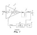
- FIG. 1is a block diagram of a prior art power amplifier system comprising a series configured arrangement of stages
- FIG. 2is a graph showing the non-linear relationship between PWR OUT and the common control signal V Control provided to the stages of the power amplifier in FIG. 1;
- FIG. 3is an efficiency curve showing the overall transmission efficiency as a function of the control signal.
- FIG. 4is a block diagram of a multi-stage power amplifier according to the present invention having a plurality of parallel-arranged stages that are independently controlled between an OFF state and an ON state.
- FIG. 1shows a high-level block diagram of a prior art power amplifier system 10 comprising a series configured arrangement of power amplifier stages.
- the power amplifier system 10utilizes a conventional, multi-stage power amplifier 12 wherein three separate power amplifier (PA) stages 14 , 16 and 18 , respectively, take a PWR IN 20 signal and through a matching network 24 produce a PWR OUT signal 22 .
- the multi-stage amplifier of FIG. 1uses several power amplifier stages rather than merely one power amplifier stage such that the overall PA 12 may achieve the desired amplification, approx., 20 dB gain, typically required by a cellular telephone with higher fidelity and with less probability of oscillation.
- the transceiver portionadjusts the transmitted power by varying the PA's 12 bias voltage or current through the V CONTROL 26 line by a PA controller 28 in response to the cellular phones digital signal processor (DSP) 30 which determines its location and associated power level with respect to its location to its MTS.
- DSPdigital signal processor
- the PA controller 28further monitors the PWR OUT 22 by a coupler 32 to further tune and adjust the multi-stage PA 12 , as shown in FIG. 1 .
- FIG. 2there is shown a graph 34 depicting the non-linear relationship 36 between PWR OUT 22 and the common control signal V CONTROL 26 provided to the stages of the power amplifier 12 in FIG. 1 .
- the relationship 36 between PWR OUT 22 and V CONTROL 26is not linear, as V CONTROL ranges from 0 to 3 volts.
- tuning to FIG. 3there is depicted an efficiency curve 40 showing the overall transmission efficiency 38 as a function of the control signal 26 .
- the power amplifierhas a maximum efficiency at a particular operating point 42 (e.g. 60% at 2 volts).
- the overall efficiency of the power amplifier 12is generally less than the maximum efficiency of 60%. If the transmitter's power amplifier always operates in the range identified as 5 dBm-33 dBm, then the power amplifier 12 has an overall average efficiency that is even less than 60% (e.g. 52%). As a result, approximately only one half of the power being inserted in the device is actually being transmitted as useful RF power, whereas the rest of the power is merely being dissipated as heat.
- a 3-volt devicethat transmits at 2 watts of power at 100% efficiency, for example, draws two-thirds of an ampere. If that same device were to operate at 60% efficiency, its current draw when transmitting at 2 watts of power would increase to approximately 1.1 amperes. Given a typical battery capacity of only 1 ampere-hour, this 60% efficiency device would have a total transmit time or “talk time” of less than 1 hour.
- DSPdigital signal processor
- ROMread only memory
- the PA controller 62utilizing the stored information in the ROM 62 to selectively power or switch on or off the combination of power amplifier stages arranged in parallel for producing the desired power level.
- three power amplifier stages 44 , 46 and 48are arranged and connected in parallel to form a multi-stage power amplifier.
- a plurality of multi-stage power amplifiersmay be connected together wherein each multi-stage power amplifier has more than one power amplifier stage arranged in parallel for also selectively switching on or off one or more of the power amplifier stages in one or more multi-stage power amplifiers to produce the desired power level.
Landscapes
- Engineering & Computer Science (AREA)
- Power Engineering (AREA)
- Amplifiers (AREA)
- Transmitters (AREA)
Abstract
Description
Claims (20)
Priority Applications (1)
| Application Number | Priority Date | Filing Date | Title |
|---|---|---|---|
| US09/361,865US6377117B2 (en) | 1999-07-27 | 1999-07-27 | Method and system for efficiently transmitting energy from an RF device |
Applications Claiming Priority (1)
| Application Number | Priority Date | Filing Date | Title |
|---|---|---|---|
| US09/361,865US6377117B2 (en) | 1999-07-27 | 1999-07-27 | Method and system for efficiently transmitting energy from an RF device |
Publications (2)
| Publication Number | Publication Date |
|---|---|
| US20020008575A1 US20020008575A1 (en) | 2002-01-24 |
| US6377117B2true US6377117B2 (en) | 2002-04-23 |
Family
ID=23423737
Family Applications (1)
| Application Number | Title | Priority Date | Filing Date |
|---|---|---|---|
| US09/361,865Expired - LifetimeUS6377117B2 (en) | 1999-07-27 | 1999-07-27 | Method and system for efficiently transmitting energy from an RF device |
Country Status (1)
| Country | Link |
|---|---|
| US (1) | US6377117B2 (en) |
Cited By (43)
| Publication number | Priority date | Publication date | Assignee | Title |
|---|---|---|---|---|
| US6512416B2 (en)* | 2000-07-03 | 2003-01-28 | Broadcom Corporation | Extended range variable gain amplifier |
| US20030232609A1 (en)* | 2002-06-14 | 2003-12-18 | Yates David L. | Switchable gain amplifier |
| US6683498B2 (en)* | 2000-07-03 | 2004-01-27 | Broadcom Corporation | Protection circuit for extending headroom with off-chip inductors |
| US20040105033A1 (en)* | 2002-12-02 | 2004-06-03 | Broadcom Corporation | Amplifier assembly including variable gain amplifier, parallel programmable amplifiers, and AGC |
| US20040104771A1 (en)* | 2002-12-02 | 2004-06-03 | Broadcom Corporation | Gain control methods and systems in an amplifier assembly |
| US6791407B2 (en)* | 2002-01-15 | 2004-09-14 | Mia-Com Eurotec B.V. | Switchable power amplifier |
| US20050130617A1 (en)* | 2002-12-02 | 2005-06-16 | Broadcom Corporation | Variable-gain low noise amplifier for digital terrestrial applications |
| US20090131074A1 (en)* | 2007-11-20 | 2009-05-21 | Intermec Ip Corp. | Utilizing location-based data to manipulate power states of embedded devices |
| US20100117727A1 (en)* | 2008-11-11 | 2010-05-13 | Massachusetts Institute Of Technology | Asymmetric multilevel outphasing architecture for rf amplifiers |
| US7982543B1 (en) | 2009-03-30 | 2011-07-19 | Triquint Semiconductor, Inc. | Switchable power amplifier |
| US8207798B1 (en) | 2009-09-09 | 2012-06-26 | Triquint Semiconductor, Inc. | Matching network with switchable capacitor bank |
| US8437720B2 (en) | 2002-12-02 | 2013-05-07 | Broadcom Corporation | Variable-gain low noise amplifier for digital terrestrial applications |
| US20140120854A1 (en)* | 2012-10-30 | 2014-05-01 | Eta Devices, Inc. | Transmitter Architecture and Related Methods |
| US8824978B2 (en) | 2012-10-30 | 2014-09-02 | Eta Devices, Inc. | RF amplifier architecture and related techniques |
| US8829993B2 (en) | 2012-10-30 | 2014-09-09 | Eta Devices, Inc. | Linearization circuits and methods for multilevel power amplifier systems |
| US20150091657A1 (en)* | 2013-09-30 | 2015-04-02 | Peregrine Semiconductor Corporation | Methods and Devices for Thermal Control in Power Amplifier Circuits |
| US20150137890A1 (en)* | 2013-11-15 | 2015-05-21 | Peregrine Semiconductor Corporation | Devices and Methods for Improving Yield of Scalable Periphery Amplifiers |
| US20150137889A1 (en)* | 2013-11-15 | 2015-05-21 | Peregrine Semiconductor Corporation | Devices and Methods for Increasing Reliability of Scalable Periphery Amplifiers |
| US20150137845A1 (en)* | 2013-11-15 | 2015-05-21 | Peregrine Semiconductor Corporation | Methods and Devices for Testing Segmented Electronic Assemblies |
| US9276527B2 (en) | 2013-09-30 | 2016-03-01 | Peregrine Semiconductor Corporation | Methods and devices for impedance matching in power amplifier circuits |
| US9294056B2 (en) | 2013-03-12 | 2016-03-22 | Peregrine Semiconductor Corporation | Scalable periphery tunable matching power amplifier |
| US20160164494A1 (en)* | 2013-07-16 | 2016-06-09 | Micron Technology, Inc. | Semiconductor device and method for adjusting impedance of output circuit |
| US9537456B2 (en) | 2012-10-30 | 2017-01-03 | Eta Devices, Inc. | Asymmetric multilevel backoff amplifier with radio-frequency splitter |
| US9660520B2 (en) | 2013-04-09 | 2017-05-23 | Massachusetts Institute Of Technology | Method and apparatus to provide power conversion with high power factor |
| US9667139B2 (en) | 2008-05-08 | 2017-05-30 | Massachusetts Institute Of Technology | Power converter with capacitive energy transfer and fast dynamic response |
| US9768731B2 (en) | 2014-07-23 | 2017-09-19 | Eta Devices, Inc. | Linearity and noise improvement for multilevel power amplifier systems using multi-pulse drain transitions |
| US9825545B2 (en) | 2013-10-29 | 2017-11-21 | Massachusetts Institute Of Technology | Switched-capacitor split drive transformer power conversion circuit |
| US9979421B2 (en) | 2015-03-02 | 2018-05-22 | Eta Devices, Inc. | Digital pre-distortion (DPD) training and calibration system and related techniques |
| US10075064B2 (en) | 2014-07-03 | 2018-09-11 | Massachusetts Institute Of Technology | High-frequency, high density power factor correction conversion for universal input grid interface |
| US10917007B2 (en) | 2011-05-05 | 2021-02-09 | Psemi Corporation | Power converter with modular stages connected by floating terminals |
| US11121714B2 (en) | 2017-10-30 | 2021-09-14 | Micron Technology, Inc. | Apparatuses and methods for identifying memory devices of a semiconductor device sharing an external resistance |
| US11211861B2 (en) | 2011-05-05 | 2021-12-28 | Psemi Corporation | DC-DC converter with modular stages |
| US11212142B2 (en) | 2017-06-22 | 2021-12-28 | Micron Technology, Inc. | Timing based arbitration methods and apparatuses for calibrating impedances of a semiconductor device |
| US11237579B2 (en) | 2019-11-19 | 2022-02-01 | Micron Technology, Inc. | Apparatuses and methods for ZQ calibration |
| US11303205B2 (en) | 2011-05-05 | 2022-04-12 | Psemi Corporation | Power converters with modular stages |
| US11316424B2 (en) | 2011-05-05 | 2022-04-26 | Psemi Corporation | Dies with switches for operating a switched-capacitor power converter |
| US11482989B2 (en) | 2016-12-09 | 2022-10-25 | Micron Technology, Inc. | Apparatuses and methods for calibrating adjustable impedances of a semiconductor device |
| US11901817B2 (en) | 2013-03-15 | 2024-02-13 | Psemi Corporation | Protection of switched capacitor power converter |
| US12107495B2 (en) | 2015-07-08 | 2024-10-01 | Psemi Corporation | Switched-capacitor power converters |
| US12176815B2 (en) | 2011-12-19 | 2024-12-24 | Psemi Corporation | Switched-capacitor circuit control in power converters |
| US12212232B2 (en) | 2013-03-15 | 2025-01-28 | Psemi Corporation | Power supply for gate driver in switched-capacitor circuit |
| US12237765B2 (en) | 2015-03-13 | 2025-02-25 | Psemi Corporation | DC-DC transformer with inductor for the facilitation of adiabatic inter-capacitor charge transport |
| US12438135B2 (en) | 2011-10-18 | 2025-10-07 | Psemi Corporation | Multilayer power, converter with devices having reduced lateral current |
Families Citing this family (21)
| Publication number | Priority date | Publication date | Assignee | Title |
|---|---|---|---|---|
| US7444124B1 (en) | 2003-05-14 | 2008-10-28 | Marvell International Ltd. | Adjustable segmented power amplifier |
| US9026070B2 (en) | 2003-12-18 | 2015-05-05 | Qualcomm Incorporated | Low-power wireless diversity receiver with multiple receive paths |
| US9450665B2 (en) | 2005-10-19 | 2016-09-20 | Qualcomm Incorporated | Diversity receiver for wireless communication |
| US7436253B2 (en)* | 2006-12-06 | 2008-10-14 | Broadcom Corporation | Method and system for fast calibration to cancel phase feedthrough |
| US20090146784A1 (en)* | 2007-12-10 | 2009-06-11 | Mohammad Soleimani | Method and System for Variable Power Amplifier Bias in RFID Transceivers |
| US9178669B2 (en) | 2011-05-17 | 2015-11-03 | Qualcomm Incorporated | Non-adjacent carrier aggregation architecture |
| US9252827B2 (en) | 2011-06-27 | 2016-02-02 | Qualcomm Incorporated | Signal splitting carrier aggregation receiver architecture |
| US9154179B2 (en) | 2011-06-29 | 2015-10-06 | Qualcomm Incorporated | Receiver with bypass mode for improved sensitivity |
| US12081243B2 (en) | 2011-08-16 | 2024-09-03 | Qualcomm Incorporated | Low noise amplifiers with combined outputs |
| US8774334B2 (en) | 2011-11-09 | 2014-07-08 | Qualcomm Incorporated | Dynamic receiver switching |
| US9172402B2 (en) | 2012-03-02 | 2015-10-27 | Qualcomm Incorporated | Multiple-input and multiple-output carrier aggregation receiver reuse architecture |
| US9362958B2 (en) | 2012-03-02 | 2016-06-07 | Qualcomm Incorporated | Single chip signal splitting carrier aggregation receiver architecture |
| US9118439B2 (en) | 2012-04-06 | 2015-08-25 | Qualcomm Incorporated | Receiver for imbalanced carriers |
| WO2013169209A1 (en)* | 2012-05-11 | 2013-11-14 | Agency For Science, Technology And Research | Communication devices and methods for controlling a communication device |
| US9154356B2 (en) | 2012-05-25 | 2015-10-06 | Qualcomm Incorporated | Low noise amplifiers for carrier aggregation |
| US9867194B2 (en) | 2012-06-12 | 2018-01-09 | Qualcomm Incorporated | Dynamic UE scheduling with shared antenna and carrier aggregation |
| US9300420B2 (en) | 2012-09-11 | 2016-03-29 | Qualcomm Incorporated | Carrier aggregation receiver architecture |
| US9543903B2 (en) | 2012-10-22 | 2017-01-10 | Qualcomm Incorporated | Amplifiers with noise splitting |
| US8995591B2 (en) | 2013-03-14 | 2015-03-31 | Qualcomm, Incorporated | Reusing a single-chip carrier aggregation receiver to support non-cellular diversity |
| TWI563719B (en)* | 2015-05-28 | 2016-12-21 | Airoha Tech Corp | Wideband front-end device and method for filtering rf signal |
| US10177722B2 (en) | 2016-01-12 | 2019-01-08 | Qualcomm Incorporated | Carrier aggregation low-noise amplifier with tunable integrated power splitter |
Citations (2)
| Publication number | Priority date | Publication date | Assignee | Title |
|---|---|---|---|---|
| US4598252A (en)* | 1984-07-06 | 1986-07-01 | Itt Corporation | Variable gain power amplifier |
| US5194822A (en)* | 1990-08-14 | 1993-03-16 | Alcatel Cit | Automatic gain control method and device for a variable gain amplifier and application thereof to controlling the gain of a tuner, in particular for a videocommunication network |
- 1999
- 1999-07-27USUS09/361,865patent/US6377117B2/ennot_activeExpired - Lifetime
Patent Citations (2)
| Publication number | Priority date | Publication date | Assignee | Title |
|---|---|---|---|---|
| US4598252A (en)* | 1984-07-06 | 1986-07-01 | Itt Corporation | Variable gain power amplifier |
| US5194822A (en)* | 1990-08-14 | 1993-03-16 | Alcatel Cit | Automatic gain control method and device for a variable gain amplifier and application thereof to controlling the gain of a tuner, in particular for a videocommunication network |
Cited By (110)
| Publication number | Priority date | Publication date | Assignee | Title |
|---|---|---|---|---|
| US6952134B2 (en) | 2000-07-03 | 2005-10-04 | Broadcom Corporation | Protection circuit for extending headroom with off-chip inductors |
| US6683498B2 (en)* | 2000-07-03 | 2004-01-27 | Broadcom Corporation | Protection circuit for extending headroom with off-chip inductors |
| US6696893B2 (en) | 2000-07-03 | 2004-02-24 | Broadcom Corporation | Extended range variable gain amplifier |
| US6512416B2 (en)* | 2000-07-03 | 2003-01-28 | Broadcom Corporation | Extended range variable gain amplifier |
| US7190219B2 (en) | 2000-07-03 | 2007-03-13 | Broadcom Corporation | Extended range variable-gain amplifier |
| US20040135636A1 (en)* | 2000-07-03 | 2004-07-15 | Burns Lawrence M. | Protection circuit for extending headroom with off-chip inductors |
| US6791407B2 (en)* | 2002-01-15 | 2004-09-14 | Mia-Com Eurotec B.V. | Switchable power amplifier |
| US20030232609A1 (en)* | 2002-06-14 | 2003-12-18 | Yates David L. | Switchable gain amplifier |
| US7039377B2 (en)* | 2002-06-14 | 2006-05-02 | Skyworks Solutions, Inc. | Switchable gain amplifier |
| US7501888B2 (en) | 2002-12-02 | 2009-03-10 | Broadcom Corporation | Gain control methods and systems in an amplifier assembly |
| US20100277235A1 (en)* | 2002-12-02 | 2010-11-04 | Broadcom Corporation | Gain Control Methods and Systems in an Amplifier Assembly |
| US20050200406A1 (en)* | 2002-12-02 | 2005-09-15 | Broadcom Corporation | Gain control methods and systems in an amplifier assembly |
| US20050208910A1 (en)* | 2002-12-02 | 2005-09-22 | Broadcom Corporation | Variable-gain low noise amplifier for digital terrestrial applications |
| US20040189382A1 (en)* | 2002-12-02 | 2004-09-30 | Broadcom Corporation | Gain control methods and systems in an amplifier assembly |
| US6798286B2 (en) | 2002-12-02 | 2004-09-28 | Broadcom Corporation | Gain control methods and systems in an amplifier assembly |
| US7068100B2 (en) | 2002-12-02 | 2006-06-27 | Broadcom Corporation | Gain control methods and systems in an amplifier assembly |
| US7183845B2 (en) | 2002-12-02 | 2007-02-27 | Broadcom Corporation | Gain control methods and systems in an amplifier assembly |
| US20040104771A1 (en)* | 2002-12-02 | 2004-06-03 | Broadcom Corporation | Gain control methods and systems in an amplifier assembly |
| US20070159244A1 (en)* | 2002-12-02 | 2007-07-12 | Broadcom Corporation | Gain control methods and systems in an amplifier assembly |
| US7260377B2 (en) | 2002-12-02 | 2007-08-21 | Broadcom Corporation | Variable-gain low noise amplifier for digital terrestrial applications |
| US7471941B2 (en) | 2002-12-02 | 2008-12-30 | Broadcom Corporation | Amplifier assembly including variable gain amplifier, parallel programmable amplifiers, and AGC |
| US20090040059A1 (en)* | 2002-12-02 | 2009-02-12 | Broadcom Corporation | Apparatus to Monitor Process-Based Parameters of an Integrated Circuit (IC) Substrate |
| US20040105033A1 (en)* | 2002-12-02 | 2004-06-03 | Broadcom Corporation | Amplifier assembly including variable gain amplifier, parallel programmable amplifiers, and AGC |
| US20090066414A1 (en)* | 2002-12-02 | 2009-03-12 | Broadcom Corporation | Gain control methods and systems in an amplifier assembly |
| US8437720B2 (en) | 2002-12-02 | 2013-05-07 | Broadcom Corporation | Variable-gain low noise amplifier for digital terrestrial applications |
| US7634244B2 (en) | 2002-12-02 | 2009-12-15 | Broadcom Corporation | Variable-gain low noise amplifier for digital terrestrial applications |
| US8094033B2 (en) | 2002-12-02 | 2012-01-10 | Broadcom Corporation | Apparatus to monitor process-based parameters of an integrated circuit (IC) substrate |
| US7791412B2 (en) | 2002-12-02 | 2010-09-07 | Broadcom Corporation | Gain control methods and systems in an amplifier assembly |
| US20050130617A1 (en)* | 2002-12-02 | 2005-06-16 | Broadcom Corporation | Variable-gain low noise amplifier for digital terrestrial applications |
| US7969241B2 (en) | 2002-12-02 | 2011-06-28 | Broadcom Corporation | Gain control methods and systems in an amplifier assembly |
| US20090131074A1 (en)* | 2007-11-20 | 2009-05-21 | Intermec Ip Corp. | Utilizing location-based data to manipulate power states of embedded devices |
| US8064924B2 (en)* | 2007-11-20 | 2011-11-22 | Intermec Ip Corp. | Utilizing location-based data to manipulate power states of embedded devices |
| US10541611B2 (en) | 2008-05-08 | 2020-01-21 | Massachusetts Institute Of Technology | Power converter with capacitive energy transfer and fast dynamic response |
| US9667139B2 (en) | 2008-05-08 | 2017-05-30 | Massachusetts Institute Of Technology | Power converter with capacitive energy transfer and fast dynamic response |
| US11245330B2 (en) | 2008-05-08 | 2022-02-08 | Massachusetts Institute Of Technology | Power converter with capacitive energy transfer and fast dynamic response |
| US11736010B2 (en) | 2008-05-08 | 2023-08-22 | Massachusetts Institute Of Technology | Power converter with capacitive energy transfer and fast dynamic response |
| US12431801B2 (en) | 2008-05-08 | 2025-09-30 | Massachusetts Institute Of Technology | Power converter with capacitive energy transfer and fast dynamic response |
| US20100117727A1 (en)* | 2008-11-11 | 2010-05-13 | Massachusetts Institute Of Technology | Asymmetric multilevel outphasing architecture for rf amplifiers |
| US8659353B2 (en) | 2008-11-11 | 2014-02-25 | Massachusetts Institute Of Technology | Asymmetric multilevel outphasing architecture for RF amplifiers |
| US20140125412A1 (en)* | 2008-11-11 | 2014-05-08 | Joel L. Dawson | Asymmetric Multilevel Outphasing Architecture For RF Amplifiers |
| US8164384B2 (en)* | 2008-11-11 | 2012-04-24 | Massachusetts Institute Of Technology | Asymmetric multilevel outphasing architecture for RF amplifiers |
| US8957727B2 (en)* | 2008-11-11 | 2015-02-17 | Massachusetts Institute Of Technology | Asymmetric multilevel outphasing architecture for RF amplifiers |
| US8026763B2 (en)* | 2008-11-11 | 2011-09-27 | Massachusetts Institute Of Technology | Asymmetric multilevel outphasing architecture for RF amplifiers |
| US20110215866A1 (en)* | 2008-11-11 | 2011-09-08 | Massachusetts Institute Of Technology | asymmetric multilevel outphasing architecture for rf amplifiers |
| US7982543B1 (en) | 2009-03-30 | 2011-07-19 | Triquint Semiconductor, Inc. | Switchable power amplifier |
| US8207798B1 (en) | 2009-09-09 | 2012-06-26 | Triquint Semiconductor, Inc. | Matching network with switchable capacitor bank |
| US11791723B2 (en) | 2010-12-30 | 2023-10-17 | Psemi Corporation | Switched-capacitor converter configurations with phase switches and stack switches |
| US11211861B2 (en) | 2011-05-05 | 2021-12-28 | Psemi Corporation | DC-DC converter with modular stages |
| US10917007B2 (en) | 2011-05-05 | 2021-02-09 | Psemi Corporation | Power converter with modular stages connected by floating terminals |
| US12381482B2 (en) | 2011-05-05 | 2025-08-05 | Psemi Corporation | Power converter with modular stages connected by floating terminals |
| US12341424B2 (en) | 2011-05-05 | 2025-06-24 | Psemi Corporation | Power converters with modular stages |
| US11764670B2 (en) | 2011-05-05 | 2023-09-19 | Psemi Corporation | DC-DC converter with modular stages |
| US11316424B2 (en) | 2011-05-05 | 2022-04-26 | Psemi Corporation | Dies with switches for operating a switched-capacitor power converter |
| US11303205B2 (en) | 2011-05-05 | 2022-04-12 | Psemi Corporation | Power converters with modular stages |
| US12438135B2 (en) | 2011-10-18 | 2025-10-07 | Psemi Corporation | Multilayer power, converter with devices having reduced lateral current |
| US12176815B2 (en) | 2011-12-19 | 2024-12-24 | Psemi Corporation | Switched-capacitor circuit control in power converters |
| US10658981B2 (en) | 2012-10-30 | 2020-05-19 | Eta Devices, Inc. | Linearization circuits and methods for multilevel power amplifier systems |
| US9209758B2 (en)* | 2012-10-30 | 2015-12-08 | Eta Devices, Inc. | RF amplifier having discrete supply voltages |
| US8824978B2 (en) | 2012-10-30 | 2014-09-02 | Eta Devices, Inc. | RF amplifier architecture and related techniques |
| US9172336B2 (en) | 2012-10-30 | 2015-10-27 | Ela Devices, Inc. | Method and apparatus for multilevel power amplification |
| US8829993B2 (en) | 2012-10-30 | 2014-09-09 | Eta Devices, Inc. | Linearization circuits and methods for multilevel power amplifier systems |
| US9160287B2 (en) | 2012-10-30 | 2015-10-13 | Eta Devices, Inc. | Linearization circuits and methods for multilevel power amplifier systems |
| US9490752B2 (en) | 2012-10-30 | 2016-11-08 | Eta Devices, Inc. | RF amplifier having a transition shaping filter |
| US9537456B2 (en) | 2012-10-30 | 2017-01-03 | Eta Devices, Inc. | Asymmetric multilevel backoff amplifier with radio-frequency splitter |
| US9166536B2 (en)* | 2012-10-30 | 2015-10-20 | Eta Devices, Inc. | Transmitter architecture and related methods |
| US20140335805A1 (en)* | 2012-10-30 | 2014-11-13 | Eta Devices, Inc. | RF Amplifier Architecture and Related Techniques |
| US20150194940A1 (en)* | 2012-10-30 | 2015-07-09 | ETA Devices, Inc | RF Amplifier Having Discrete Supply Voltages |
| US20140120854A1 (en)* | 2012-10-30 | 2014-05-01 | Eta Devices, Inc. | Transmitter Architecture and Related Methods |
| US9020453B2 (en)* | 2012-10-30 | 2015-04-28 | Eta Devices, Inc. | RF amplifier architecture and related techniques |
| US10164577B2 (en) | 2012-10-30 | 2018-12-25 | Eta Devices, Inc. | Linearization circuits and methods for multilevel power amplifier systems |
| US9768732B2 (en) | 2012-10-30 | 2017-09-19 | Eta Devices, Inc. | Asymmetric multilevel backoff amplifier with radio-frequency splitter |
| US10038461B2 (en)* | 2012-10-30 | 2018-07-31 | Eta Devices, Inc. | RF amplifier having a transition shaping filter |
| US11811367B2 (en) | 2013-03-12 | 2023-11-07 | Psemi Corporation | Scalable periphery tunable matching power amplifier |
| US9847759B2 (en) | 2013-03-12 | 2017-12-19 | Peregrine Semiconductor Corporation | Scalable periphery tunable matching power amplifier |
| US10756684B2 (en) | 2013-03-12 | 2020-08-25 | Psemi Corporation | Scalable periphery tunable matching power amplifier |
| US9294056B2 (en) | 2013-03-12 | 2016-03-22 | Peregrine Semiconductor Corporation | Scalable periphery tunable matching power amplifier |
| US11323078B2 (en) | 2013-03-12 | 2022-05-03 | Psemi Corporation | Scalable periphery tunable matching power amplifier |
| US12143010B2 (en) | 2013-03-15 | 2024-11-12 | Psemi Corporation | Protection of switched capacitor power converter |
| US12113438B2 (en) | 2013-03-15 | 2024-10-08 | Psemi Corporation | Protection of switched capacitor power converter |
| US12212232B2 (en) | 2013-03-15 | 2025-01-28 | Psemi Corporation | Power supply for gate driver in switched-capacitor circuit |
| US11901817B2 (en) | 2013-03-15 | 2024-02-13 | Psemi Corporation | Protection of switched capacitor power converter |
| US9660520B2 (en) | 2013-04-09 | 2017-05-23 | Massachusetts Institute Of Technology | Method and apparatus to provide power conversion with high power factor |
| US20160164494A1 (en)* | 2013-07-16 | 2016-06-09 | Micron Technology, Inc. | Semiconductor device and method for adjusting impedance of output circuit |
| US9614497B2 (en)* | 2013-07-16 | 2017-04-04 | Micron Technology, Inc. | Semiconductor device and method for adjusting impedance of output circuit |
| US20150091657A1 (en)* | 2013-09-30 | 2015-04-02 | Peregrine Semiconductor Corporation | Methods and Devices for Thermal Control in Power Amplifier Circuits |
| US9331643B2 (en)* | 2013-09-30 | 2016-05-03 | Peregrine Semiconductor Corporation | Methods and devices for thermal control in power amplifier circuits |
| US9276527B2 (en) | 2013-09-30 | 2016-03-01 | Peregrine Semiconductor Corporation | Methods and devices for impedance matching in power amplifier circuits |
| US9825545B2 (en) | 2013-10-29 | 2017-11-21 | Massachusetts Institute Of Technology | Switched-capacitor split drive transformer power conversion circuit |
| US9407212B2 (en)* | 2013-11-15 | 2016-08-02 | Peregrine Semiconductor Corporation | Devices and methods for improving yield of scalable periphery amplifiers |
| US9438185B2 (en)* | 2013-11-15 | 2016-09-06 | Peregrine Semiconductor Corporation | Devices and methods for increasing reliability of scalable periphery amplifiers |
| US20150137845A1 (en)* | 2013-11-15 | 2015-05-21 | Peregrine Semiconductor Corporation | Methods and Devices for Testing Segmented Electronic Assemblies |
| US9391566B2 (en)* | 2013-11-15 | 2016-07-12 | Peregrine Semiconductor Corporation | Methods and devices for testing segmented electronic assemblies |
| US20150137889A1 (en)* | 2013-11-15 | 2015-05-21 | Peregrine Semiconductor Corporation | Devices and Methods for Increasing Reliability of Scalable Periphery Amplifiers |
| US20150137890A1 (en)* | 2013-11-15 | 2015-05-21 | Peregrine Semiconductor Corporation | Devices and Methods for Improving Yield of Scalable Periphery Amplifiers |
| US9654067B2 (en) | 2013-11-15 | 2017-05-16 | Peregrine Semiconductor Corporation | Devices and methods for improving yield of scalable periphery amplifiers |
| US9660598B2 (en) | 2013-11-15 | 2017-05-23 | Peregrine Semiconductor Corporation | Devices and methods for increasing reliability of scalable periphery amplifiers |
| US10075064B2 (en) | 2014-07-03 | 2018-09-11 | Massachusetts Institute Of Technology | High-frequency, high density power factor correction conversion for universal input grid interface |
| US9768731B2 (en) | 2014-07-23 | 2017-09-19 | Eta Devices, Inc. | Linearity and noise improvement for multilevel power amplifier systems using multi-pulse drain transitions |
| US9979421B2 (en) | 2015-03-02 | 2018-05-22 | Eta Devices, Inc. | Digital pre-distortion (DPD) training and calibration system and related techniques |
| US12237765B2 (en) | 2015-03-13 | 2025-02-25 | Psemi Corporation | DC-DC transformer with inductor for the facilitation of adiabatic inter-capacitor charge transport |
| US12107495B2 (en) | 2015-07-08 | 2024-10-01 | Psemi Corporation | Switched-capacitor power converters |
| US11916527B2 (en) | 2016-12-09 | 2024-02-27 | Lodestar Licensing Group Llc | Apparatuses and methods for calibrating adjustable impedances of a semiconductor device |
| US12231106B2 (en) | 2016-12-09 | 2025-02-18 | Lodestar Licensing Group Llc | Apparatuses and methods for calibrating adjustable impedances of a semiconductor device |
| US12249969B2 (en) | 2016-12-09 | 2025-03-11 | Lodestar Licensing Group Llc | Apparatuses and methods for calibrating adjustable impedances of a semiconductor device |
| US11482989B2 (en) | 2016-12-09 | 2022-10-25 | Micron Technology, Inc. | Apparatuses and methods for calibrating adjustable impedances of a semiconductor device |
| US11212142B2 (en) | 2017-06-22 | 2021-12-28 | Micron Technology, Inc. | Timing based arbitration methods and apparatuses for calibrating impedances of a semiconductor device |
| US12184280B2 (en) | 2017-10-30 | 2024-12-31 | Lodestar Licensing Group, Llc | Apparatuses and methods for identifying memory devices of a semiconductor device sharing an external resistance |
| US11728812B2 (en) | 2017-10-30 | 2023-08-15 | Micron Technology, Inc. | Apparatuses and methods for identifying memory devices of a semiconductor device sharing an external resistance |
| US11121714B2 (en) | 2017-10-30 | 2021-09-14 | Micron Technology, Inc. | Apparatuses and methods for identifying memory devices of a semiconductor device sharing an external resistance |
| US11237579B2 (en) | 2019-11-19 | 2022-02-01 | Micron Technology, Inc. | Apparatuses and methods for ZQ calibration |
Also Published As
| Publication number | Publication date |
|---|---|
| US20020008575A1 (en) | 2002-01-24 |
Similar Documents
| Publication | Publication Date | Title |
|---|---|---|
| US6377117B2 (en) | Method and system for efficiently transmitting energy from an RF device | |
| US7565117B2 (en) | Control of power amplifiers in devices using transmit beamforming | |
| KR100312367B1 (en) | Mobile communication device and method | |
| EP1127406B1 (en) | High efficiency power amplifier | |
| JP3171141B2 (en) | Mobile communication transmitter and control method thereof | |
| EP1576726B1 (en) | Composite amplifier structure | |
| US8718581B2 (en) | Method and apparatus for optimizing current consumption of amplifiers with power control | |
| JP2005513943A (en) | Power amplifier | |
| EP1104119B1 (en) | Transmitter adjusting output power | |
| EP1573906B1 (en) | Preserving linearity of an isolator-free power amplifier by dynamically adjusting gain and phase | |
| EP1573904B1 (en) | Preserving linearity of an isolator-free power amplifier by dynamically switching active devices | |
| EP1229642B1 (en) | Power amplifier circuit for amplifying RF-Signals | |
| US20010046846A1 (en) | Mobile terminal and reception gain control method in mobile terminal | |
| WO2003081768A2 (en) | Improving the efficiency of power amplifiers in devices using transmit beamforming | |
| US7076218B2 (en) | Control method and circuit for using a heterojunction bipolar transistor power amplifier in a zero intermediate frequency architecture transmitter | |
| EP1573905A1 (en) | Preserving linearity of an isolator-free power amplifier by dynamically adjusting bias and supply of active devices | |
| KR20010040179A (en) | Apparatus and method for controlling transmission power of mobile station | |
| JPH0374982B2 (en) | ||
| JP2000252843A (en) | Transmission power control circuit | |
| JP2000049628A (en) | Transmission output control method and transmission output control circuit | |
| KR20030077311A (en) | mobile communication terminal having an linear output control device |
Legal Events
| Date | Code | Title | Description |
|---|---|---|---|
| AS | Assignment | Owner name:CREDIT SUISSE FIRST BOSTON, NEW YORK Free format text:SECURITY INTEREST;ASSIGNOR:CONEXANT SYSTEMS, INC.;REEL/FRAME:010450/0899 Effective date:19981221 | |
| AS | Assignment | Owner name:CONEXANT SYSTEMS, INC., CALIFORNIA Free format text:ASSIGNMENT OF ASSIGNORS INTEREST;ASSIGNORS:OSKOWSKY, MARK;AGAHI-KESHCH, DARIOUSH;REEL/FRAME:010716/0063;SIGNING DATES FROM 19990921 TO 19991021 | |
| AS | Assignment | Owner name:CONEXANT SYSTEMS, INC., CALIFORNIA Free format text:RELEASE OF SECURITY INTEREST;ASSIGNOR:CREDIT SUISSE FIRST BOSTON;REEL/FRAME:012252/0865 Effective date:20011018 Owner name:BROOKTREE CORPORATION, CALIFORNIA Free format text:RELEASE OF SECURITY INTEREST;ASSIGNOR:CREDIT SUISSE FIRST BOSTON;REEL/FRAME:012252/0865 Effective date:20011018 Owner name:BROOKTREE WORLDWIDE SALES CORPORATION, CALIFORNIA Free format text:RELEASE OF SECURITY INTEREST;ASSIGNOR:CREDIT SUISSE FIRST BOSTON;REEL/FRAME:012252/0865 Effective date:20011018 Owner name:CONEXANT SYSTEMS WORLDWIDE, INC., CALIFORNIA Free format text:RELEASE OF SECURITY INTEREST;ASSIGNOR:CREDIT SUISSE FIRST BOSTON;REEL/FRAME:012252/0865 Effective date:20011018 | |
| STCF | Information on status: patent grant | Free format text:PATENTED CASE | |
| AS | Assignment | Owner name:WASHINGTON SUB, INC., CALIFORNIA Free format text:ASSIGNMENT OF ASSIGNORS INTEREST;ASSIGNOR:CONEXANT SYSTEMS, INC.;REEL/FRAME:013153/0682 Effective date:20020625 | |
| AS | Assignment | Owner name:ALPHA INDUSTRIES, INC., MASSACHUSETTS Free format text:MERGER;ASSIGNOR:WASHINGTON SUB, INC.;REEL/FRAME:013177/0937 Effective date:20020625 Owner name:SKYWORKS SOLUTIONS, INC., CALIFORNIA Free format text:MERGER;ASSIGNOR:ALPHA INDUSTRIES, INC.;REEL/FRAME:013221/0837 Effective date:20020625 | |
| AS | Assignment | Owner name:CONEXANT SYSTEMS, INC., CALIFORNIA Free format text:SECURITY INTEREST;ASSIGNOR:ALPHA INDUSTRIES, INC.;REEL/FRAME:013240/0860 Effective date:20020625 | |
| AS | Assignment | Owner name:ALPHA INDUSTRIES, INC., MASSACHUSETTS Free format text:RELEASE AND RECONVEYANCE/SECURITY INTEREST;ASSIGNOR:CONEXANT SYSTEMS, INC.;REEL/FRAME:014580/0880 Effective date:20030307 | |
| FEPP | Fee payment procedure | Free format text:PAYOR NUMBER ASSIGNED (ORIGINAL EVENT CODE: ASPN); ENTITY STATUS OF PATENT OWNER: LARGE ENTITY | |
| FPAY | Fee payment | Year of fee payment:4 | |
| FPAY | Fee payment | Year of fee payment:8 | |
| FEPP | Fee payment procedure | Free format text:PAYOR NUMBER ASSIGNED (ORIGINAL EVENT CODE: ASPN); ENTITY STATUS OF PATENT OWNER: LARGE ENTITY Free format text:PAYER NUMBER DE-ASSIGNED (ORIGINAL EVENT CODE: RMPN); ENTITY STATUS OF PATENT OWNER: LARGE ENTITY | |
| FPAY | Fee payment | Year of fee payment:12 |