US6377051B1 - Relay test set using computer controlled voltage supply to stimulate both voltage and current transformers - Google Patents
Relay test set using computer controlled voltage supply to stimulate both voltage and current transformersDownload PDFInfo
- Publication number
- US6377051B1 US6377051B1US09/454,907US45490799AUS6377051B1US 6377051 B1US6377051 B1US 6377051B1US 45490799 AUS45490799 AUS 45490799AUS 6377051 B1US6377051 B1US 6377051B1
- Authority
- US
- United States
- Prior art keywords
- voltage
- current
- test set
- relay
- microcomputer
- Prior art date
- Legal status (The legal status is an assumption and is not a legal conclusion. Google has not performed a legal analysis and makes no representation as to the accuracy of the status listed.)
- Expired - Fee Related
Links
- 238000012360testing methodMethods0.000titleclaimsabstractdescription46
- 230000001681protective effectEffects0.000claimsabstractdescription17
- 239000011159matrix materialSubstances0.000claimsabstractdescription9
- 238000002347injectionMethods0.000claimsdescription3
- 239000007924injectionSubstances0.000claimsdescription3
- 238000012544monitoring processMethods0.000claims1
- 238000010586diagramMethods0.000description5
- 206010065929Cardiovascular insufficiencyDiseases0.000description1
- 238000012986modificationMethods0.000description1
- 230000004048modificationEffects0.000description1
- 230000007935neutral effectEffects0.000description1
Images


Classifications
- G—PHYSICS
- G01—MEASURING; TESTING
- G01R—MEASURING ELECTRIC VARIABLES; MEASURING MAGNETIC VARIABLES
- G01R31/00—Arrangements for testing electric properties; Arrangements for locating electric faults; Arrangements for electrical testing characterised by what is being tested not provided for elsewhere
- G01R31/327—Testing of circuit interrupters, switches or circuit-breakers
- G01R31/3277—Testing of circuit interrupters, switches or circuit-breakers of low voltage devices, e.g. domestic or industrial devices, such as motor protections, relays, rotation switches
- G01R31/3278—Testing of circuit interrupters, switches or circuit-breakers of low voltage devices, e.g. domestic or industrial devices, such as motor protections, relays, rotation switches of relays, solenoids or reed switches
Definitions
- the present inventionrelates generally to the fields of protective relaying and test apparatus. More particularly, the invention relates, but is not limited to, a relay test set that utilizes a computer controlled voltage power supply to simulate secondary voltages and currents for testing a low voltage trip relay.
- a problem addressed by the present inventionis that most relay test sets having the ability to inject a minimum of ten amps of alternating current at fifty volts are large and expensive. These large and expensive test sets also use separate supplies for the current and voltage.
- the present inventionincorporates the ability to inject both high current and voltage into the secondary inputs of a protective relay using a single computer controlled voltage power supply. By using this design, the relay test set is made to be both cost effective and portable.
- the secondary inputs of protective relaysare used to connect the metering current and voltage transformers. By injecting the voltage and current into these inputs, the test set becomes a simulator of both current and voltage transformers.
- a unique aspect of the present inventionis the use of a microcomputer module to control a variable voltage Class D power supply to vary both voltage and current as needed for the required test.
- the microcomputeralso monitors the voltage and current being injected into the unit under test, UUT, to insure the proper levels are attained.
- the present inventionaccomplishes several tasks in the area of protective relay testing.
- Typical relay test setsare large, heavy and costly.
- a small, highly efficient voltage and current sourcehas been designed. Linear power supplies are very inefficient and require large heat sinks to dissipate heat.
- a presently preferred implementation of this inventionincorporates a Class D switching amplifier design that greatly reduces the size of the power source needed to inject the correct voltage and current into the secondary inputs of a protective relay.
- a microcomputer modulemay be incorporated to monitor both current and voltage being injected into a protective relay. This microcomputer may also automatically run the required relay tests and route the voltage or current to the appropriate inputs of the protective relay by direct control of a relay matrix.
- FIG. 1is a block diagram of a relay test set in accordance with the present invention.
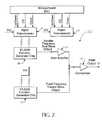
- FIG. 2is a diagram of a computer control pulse width modulator portion of the Class D amplifier in accordance with the present invention.
- FIG. 3is a diagram of the waveforms of the pulse width modulator circuitry.
- FIG. 4is a diagram of the driver circuit, output transistors and low pass filter of the Class D amplifier utilizing computer shut down of the amplifier.
- FIG. 5is a diagram showing the computer controlled routing circuit via a relay matrix and the voltage and current sensor circuit.
- FIG. 6is a flowchart of test set software logic in accordance with the present invention.
- the presently preferred embodiment depicted in FIG. 1includes a microcomputer module 1 with digital inputs and outputs (digital I/O), LCD and keyboard interface and an analog to digital converter (ADC), as shown.
- the microcomputer 1controls the output of a Class D Voltage Supply 2 .
- the voltage output of the Class D voltage supplyis monitored by using a voltage divider 3 to reduce its signal level to a point at which it can be handled by a “True RMS to DC Converter” 7 and is then input into the microcomputer's ADC circuit.
- the output of the Class D voltage supply 2is also connected to a relay matrix circuit 4 . This enables the microcomputer to route the proper signal to the secondary inputs of a unit under test (UUT) 5 .
- UUTunit under test
- the currentis routed from the Class D voltage supply 2 , through the relay matrix 4 and into the UUT 5 and returns through a current shunt 6 to the ground of the supply (the grounding of the current shunt is depicted in FIG. 5 —see R 3 ).
- the current shunt 6outputs a low level voltage, but proportional to the current, into the True RMS to DC Converter 7 and into the microcomputer module's ADC.
- FIG. 2shows more detail of a pulse width modulator (PWM) circuit 2 - 1 of the Digitally Controlled Class D Voltage Supply 2 .
- the PWM designincorporates digital potentiometers 8 and 9 , and two precision function generator IC chips 10 and 13 .
- a triangle wave output at a fixed frequency of 22 kHzis achieved from the function generator chip 13 .
- the function generator chip 10is a variable frequency sine wave generator controlled by the microcomputer 1 through the use of digital potentiometer 8 .
- the digital potentiometers 8 and 9are controlled via three control signals, “Up/Down,” “Clock” and “Chip Select” (CS). Via the microcomputer's Digital I/O, the digital potentiometer is selected by the chip select line.
- the microcomputercan set the frequency of the injected signal to the UUT 5 (FIG. 1 ).
- the digital potentiometer 9the amplitude of the injected signals can also be computer controlled.
- the digital potentiometer 9is inserted into the feedback circuit of the operational amplifier 11 to control the gain of the sine wave signal generated by the function generator chip 10 .
- the output of the gain amplifier 11 and the function generator 13is then input into an operational amplifier configured as an infinite gain comparator 12 .
- the resultis a pulse width modulation output 13 as shown in FIG. 3 (Note that FIG. 3 shows approximately 1 ⁇ 2 of the sine wave cycle as an example of the PWM output.)
- the pulse width modulator output 13is now controlled and amplified by additional circuitry 2 - 2 as shown in FIG. 4 .
- the pulse width modulation 13is input into an IGBT transistor driver IC chip 14 with high and low transistor drive outputs.
- the microcomputercan turn on and off the amplifier by use of the shut down input of the driver chip.
- the high and low outputs of the driver chipare inverted so that only one IGBT transistor, 15 or 16 , is on at any time.
- IGBT 15is turned on and IGBT 16 is turned off. This pulls the output of the series connected IGBTs to 80 VDC and isolates the output from ground.
- IGBT 16is turned on and IGBT 15 is turned off.
- the amplified pulse widthmaintains its switching frequency of 22 kHz while being modulated at the variable 50 to 60 Hz.
- the high frequencyis now to be filtered out of the desired injection signal and this is achieved using a low pass filter.
- This filtermade up of L 1 , L 2 , C 1 and C 2 , is a 12 dB / octave low pass filter and removes the high frequency component to better than ⁇ 75 dB. The result is the frequency and amplitude controlled alternating current signal.
- FIG. 5shows the configuration of the relay matrix 4 for connection of the UUT and the monitored voltage and current feedback signals to the microcomputer ADC circuit.
- the output of the Class D voltage supply 2is connected to the inputs of relays K 1 through K 7 .
- the normally open contact of relays K 1 , 2 , 3 and 4are connected to the UUT current inputs, phase A, B, C, and neutral, respectively.
- the normally open contact of relays K 5 , 6 , and 7are connected to the UUT voltage inputs, phase A, B, and C, respectively.
- This relay matrixallows the microcomputer to control where the single-phase voltage supply is injected to the UUT.
- the voltage divider circuit, R 1 and R 2reduces the output voltage to a lower level as needed at the input of the true RMS to DC converter 7 .
- the output of the current shunt, R 3is also a low level voltage signal proportional to the current as needed by the true RMS to DC converter. Both of these signals are fed through a single pole, double throw relay, K 8 . This allows the computer to monitor the desired signal, voltage or current. This completes a closed loop feedback system.
- the microcomputercan now set the desired frequency and amplitude of a voltage or current injected signal, monitor the voltage and current, and correct the signal to the proper level through the feedback circuit.
- FIG. 6depicts the software logic for the relay test system. As shown, the logic begins by deciding whether a current or voltage test is to be conducted. If a current test is to be conducted, the logic continues along the path shown on the left hand side of FIG. 6 . On the other hand, if a voltage test is to be conducted, the logic continues along the path shown on the right hand side of FIG. 6 .
- the logicdecides whether a threshold or timing delay test is to be conducted. If a threshold test is to be conducted, the logic takes the left-most branch of the flowchart. If a timing delay test is to be conducted, the logic takes the center branch of the flowchart.
- the logicIn the left-most branch (threshold test), the logic first sets the voltage output to a low value. Next, the amplifier is energized. Next, the logic decides whether the device has “picked up.” If not, the voltage level is increased and the logic again tests whether the device has picked up. Once the device has picked up, the current level is measured and recorded.
- the logicfirst sets the voltage output to an estimated target value. Next, the amplifier is energized, and then the current level is measured. The logic next determines whether the current is within tolerance. If not, the voltage level is adjusted as necessary, and the current level is again measured as indicated. Once the current is within tolerance, the timing test is performed.
- the logicfirst sets the voltage output to a target level.
- the amplifieris energized, and then the device is queried for its voltage level.
- the actual voltage levelis read, and the two results (the voltage level as determined from the query and the actual voltage level) are compared and any difference is reported.
Landscapes
- Physics & Mathematics (AREA)
- General Physics & Mathematics (AREA)
- Testing Electric Properties And Detecting Electric Faults (AREA)
Abstract
Description
Claims (6)
Priority Applications (1)
| Application Number | Priority Date | Filing Date | Title |
|---|---|---|---|
| US09/454,907US6377051B1 (en) | 1999-12-03 | 1999-12-03 | Relay test set using computer controlled voltage supply to stimulate both voltage and current transformers |
Applications Claiming Priority (1)
| Application Number | Priority Date | Filing Date | Title |
|---|---|---|---|
| US09/454,907US6377051B1 (en) | 1999-12-03 | 1999-12-03 | Relay test set using computer controlled voltage supply to stimulate both voltage and current transformers |
Publications (1)
| Publication Number | Publication Date |
|---|---|
| US6377051B1true US6377051B1 (en) | 2002-04-23 |
Family
ID=23806560
Family Applications (1)
| Application Number | Title | Priority Date | Filing Date |
|---|---|---|---|
| US09/454,907Expired - Fee RelatedUS6377051B1 (en) | 1999-12-03 | 1999-12-03 | Relay test set using computer controlled voltage supply to stimulate both voltage and current transformers |
Country Status (1)
| Country | Link |
|---|---|
| US (1) | US6377051B1 (en) |
Cited By (30)
| Publication number | Priority date | Publication date | Assignee | Title |
|---|---|---|---|---|
| US20030187520A1 (en)* | 2002-02-25 | 2003-10-02 | General Electric Company | Method and apparatus for circuit breaker node software architecture |
| US20030212835A1 (en)* | 2002-02-25 | 2003-11-13 | General Electric Company | Method and system for external clock to obtain multiple synchronized redundant computers |
| US6710482B2 (en) | 2001-08-25 | 2004-03-23 | Lucas Aerospace Power Equipment Corporation | Generator |
| US20040172569A1 (en)* | 2003-02-27 | 2004-09-02 | Faue Jon Allan | Integrated circuit memory architecture with selectively offset data and address delays to minimize skew and provide synchronization of signals at the input/output section |
| RU2262118C2 (en)* | 2003-05-05 | 2005-10-10 | Открытое акционерное общество "Всероссийский научно-исследовательский проектно-конструкторский и технологический институт релестроения с опытным производством" | Electrical block diagram of stand for testing commutation durability of commutation devices |
| US20050273207A1 (en)* | 2002-02-25 | 2005-12-08 | Dougherty John J | Distributed protection system for power distribution systems |
| US7058482B2 (en) | 2002-02-25 | 2006-06-06 | General Electric Company | Data sample and transmission modules for power distribution systems |
| US20070008670A1 (en)* | 2003-02-25 | 2007-01-11 | Fletcher David G | Protection system for for power distribution systems |
| US20070102999A1 (en)* | 2003-05-09 | 2007-05-10 | Roger Darraba | A movable or removable seat for a motor vehicle |
| US20080297201A1 (en)* | 2007-06-04 | 2008-12-04 | Quanta Computer Inc. | Complex switch control system |
| RU2344432C2 (en)* | 2006-10-16 | 2009-01-20 | Открытое акционерное общество "Всероссийский научно-исследовательский проектно-конструкторский и технологический институт релестроения с опытным производством" | Test desk electrical flow diagram |
| US20090273336A1 (en)* | 2008-05-02 | 2009-11-05 | Avo Multi-Amp Corporation D/B/A Megger | Upgradable Test Set |
| US7747356B2 (en) | 2002-02-25 | 2010-06-29 | General Electric Company | Integrated protection, monitoring, and control system |
| CN101858960A (en)* | 2010-05-31 | 2010-10-13 | 上海沪工汽车电器有限公司 | Module for testing dielectric strength of automotive relay |
| CN102087338A (en)* | 2011-01-14 | 2011-06-08 | 刘湘如 | Overload characteristic test bed of intelligent circuit breaker and control method of overload characteristic test bed |
| CN103869243A (en)* | 2014-04-10 | 2014-06-18 | 国家电网公司 | Low-voltage microcomputer protection and monitoring device operation board relay intelligent calibration method |
| CN103884982A (en)* | 2014-04-10 | 2014-06-25 | 国家电网公司 | Intelligent calibration system of operating panel relay of low-voltage microcomputer protection and monitoring device |
| CN104360265A (en)* | 2014-11-06 | 2015-02-18 | 贵州天义电器有限责任公司 | Multi-switching relay tester |
| CN105676122A (en)* | 2016-03-25 | 2016-06-15 | 国网山东省电力公司济南市长清区供电公司 | Electromagnetic relay return coefficient test platform and test method |
| US20160238658A1 (en)* | 2015-02-18 | 2016-08-18 | Freescale Semiconductor, Inc. | Wetting Current Diagnostics |
| CN108107294A (en)* | 2017-12-27 | 2018-06-01 | 国网冀北电力有限公司张家口供电公司 | A kind of microcomputer protective relay pilot system based on measurement module |
| CN108362985A (en)* | 2018-05-18 | 2018-08-03 | 西安航天动力研究所 | Solenoid valve electrical property full-automation detection device |
| DE102017202476A1 (en) | 2017-02-16 | 2018-08-16 | Db Netz Ag | Device for functional testing of a relay |
| CN109490763A (en)* | 2018-09-18 | 2019-03-19 | 浙江众合科技股份有限公司 | A kind of relay single-board universal device and test method |
| CN110850284A (en)* | 2019-12-27 | 2020-02-28 | 焦洋 | Current protection tester |
| CN111025046A (en)* | 2019-11-25 | 2020-04-17 | 上海科梁信息工程股份有限公司 | Test system, method for controlling matrix switch and storage medium |
| US11125817B2 (en) | 2019-10-14 | 2021-09-21 | Analog Devices, Inc. | Compound pin driver |
| CN113702871A (en)* | 2021-08-10 | 2021-11-26 | 国网河南省电力公司南阳供电公司 | Intelligent line finder for secondary direct-current power supply without power failure of transformer substation |
| US11264906B2 (en) | 2019-12-13 | 2022-03-01 | Analog Devices, Inc. | Compound pin driver controller |
| US11592486B2 (en) | 2020-06-05 | 2023-02-28 | Saudi Arabian Oil Company | Electromechanical relay tester |
Citations (11)
| Publication number | Priority date | Publication date | Assignee | Title |
|---|---|---|---|---|
| US4000410A (en)* | 1974-11-13 | 1976-12-28 | Sprecher & Schuh Ag | Circuit arrangement for superposing starting conditions at an electrical operating means-simulator composed of RC-elements |
| US4177419A (en) | 1976-03-15 | 1979-12-04 | Bbc Brown Boveri & Company Ltd. | Test apparatus for checking the response of protective relays |
| US4464628A (en) | 1980-11-07 | 1984-08-07 | Mitsubishi Denki Kabushiki Kaisha | Relay tester |
| US4689570A (en)* | 1984-04-26 | 1987-08-25 | Mitsubishi Denki Kabushiki Kaisha | Digital protective relay monitoring system |
| US4727318A (en)* | 1984-10-04 | 1988-02-23 | Sony/Tektronix Corporation | Apparatus for measuring characteristics of electronic devices |
| US4803434A (en) | 1988-03-18 | 1989-02-07 | Westinghouse Electric Corp. | Test device for circuit breakers having electronic trip units |
| US5101153A (en)* | 1991-01-09 | 1992-03-31 | National Semiconductor Corporation | Pin electronics test circuit for IC device testing |
| US5479315A (en)* | 1993-04-09 | 1995-12-26 | Schweitzer Engineering Laboratories, Inc. | Protective relay for power systems capable of being tested with low-level voltage and current signals |
| US5576625A (en) | 1994-02-07 | 1996-11-19 | Kabushiki Kaisha Toshiba | Test method and apparatus for testing a protective relay system |
| US5742513A (en) | 1996-05-15 | 1998-04-21 | Abb Power T&D Company Inc. | Methods and systems for automatic testing of a relay |
| US6204647B1 (en)* | 1999-06-02 | 2001-03-20 | Keithley Instruments, Inc. | Battery emulating power supply |
- 1999
- 1999-12-03USUS09/454,907patent/US6377051B1/ennot_activeExpired - Fee Related
Patent Citations (13)
| Publication number | Priority date | Publication date | Assignee | Title |
|---|---|---|---|---|
| US4000410A (en)* | 1974-11-13 | 1976-12-28 | Sprecher & Schuh Ag | Circuit arrangement for superposing starting conditions at an electrical operating means-simulator composed of RC-elements |
| US4177419A (en) | 1976-03-15 | 1979-12-04 | Bbc Brown Boveri & Company Ltd. | Test apparatus for checking the response of protective relays |
| US4464628A (en) | 1980-11-07 | 1984-08-07 | Mitsubishi Denki Kabushiki Kaisha | Relay tester |
| US4689570A (en)* | 1984-04-26 | 1987-08-25 | Mitsubishi Denki Kabushiki Kaisha | Digital protective relay monitoring system |
| US4727318A (en)* | 1984-10-04 | 1988-02-23 | Sony/Tektronix Corporation | Apparatus for measuring characteristics of electronic devices |
| US4803434A (en) | 1988-03-18 | 1989-02-07 | Westinghouse Electric Corp. | Test device for circuit breakers having electronic trip units |
| US5101153A (en)* | 1991-01-09 | 1992-03-31 | National Semiconductor Corporation | Pin electronics test circuit for IC device testing |
| US5479315A (en)* | 1993-04-09 | 1995-12-26 | Schweitzer Engineering Laboratories, Inc. | Protective relay for power systems capable of being tested with low-level voltage and current signals |
| US5576625A (en) | 1994-02-07 | 1996-11-19 | Kabushiki Kaisha Toshiba | Test method and apparatus for testing a protective relay system |
| US5666060A (en) | 1994-02-07 | 1997-09-09 | Kabushiki Kaisha Toshiba | Test method and apparatus for testing a protective relay system |
| US5786699A (en) | 1994-02-07 | 1998-07-28 | Kabushiki Kaisha Toshiba | Test method and apparatus for testing a protective relay system |
| US5742513A (en) | 1996-05-15 | 1998-04-21 | Abb Power T&D Company Inc. | Methods and systems for automatic testing of a relay |
| US6204647B1 (en)* | 1999-06-02 | 2001-03-20 | Keithley Instruments, Inc. | Battery emulating power supply |
Cited By (64)
| Publication number | Priority date | Publication date | Assignee | Title |
|---|---|---|---|---|
| US6710482B2 (en) | 2001-08-25 | 2004-03-23 | Lucas Aerospace Power Equipment Corporation | Generator |
| US7058482B2 (en) | 2002-02-25 | 2006-06-06 | General Electric Company | Data sample and transmission modules for power distribution systems |
| US7068612B2 (en) | 2002-02-25 | 2006-06-27 | General Electric Company | Method for communicating information bundled in digital message packets |
| US20030220719A1 (en)* | 2002-02-25 | 2003-11-27 | General Electric Company | Method and apparatus for centrally-controlled electrical protection system architecture reliability improvement based on sensitivity analysis |
| US20040019410A1 (en)* | 2002-02-25 | 2004-01-29 | General Electric Company | Protection system for power distribution systems |
| US20030212513A1 (en)* | 2002-02-25 | 2003-11-13 | General Electric Company | Configuring a centrally controlled circuit breaker protection system |
| US7747356B2 (en) | 2002-02-25 | 2010-06-29 | General Electric Company | Integrated protection, monitoring, and control system |
| US6892115B2 (en) | 2002-02-25 | 2005-05-10 | General Electric Company | Method and apparatus for optimized centralized critical control architecture for switchgear and power equipment |
| US6892145B2 (en) | 2002-02-25 | 2005-05-10 | General Electric Company | Method and system for conditionally triggered system data capture |
| US7068483B2 (en) | 2002-02-25 | 2006-06-27 | General Electric Company | Circuit breaker lockout |
| US8213144B2 (en) | 2002-02-25 | 2012-07-03 | General Electric Company | Circuit protection system |
| US20050273207A1 (en)* | 2002-02-25 | 2005-12-08 | Dougherty John J | Distributed protection system for power distribution systems |
| US6985784B2 (en) | 2002-02-25 | 2006-01-10 | General Electric Company | Configuring a centrally controlled circuit breaker protection system |
| US6999291B2 (en) | 2002-02-25 | 2006-02-14 | General Electric Company | Method and apparatus for node electronics unit architecture |
| US7043340B2 (en) | 2002-02-25 | 2006-05-09 | General Electric Company | Protection system for power distribution systems |
| US20030212835A1 (en)* | 2002-02-25 | 2003-11-13 | General Electric Company | Method and system for external clock to obtain multiple synchronized redundant computers |
| US7058481B2 (en) | 2002-02-25 | 2006-06-06 | General Electric Company | Method and apparatus for centrally-controlled electrical protection system architecture reliability improvement based on sensitivity analysis |
| US6909942B2 (en) | 2002-02-25 | 2005-06-21 | General Electric Company | Method for power distribution system components identification, characterization and rating |
| US20030187520A1 (en)* | 2002-02-25 | 2003-10-02 | General Electric Company | Method and apparatus for circuit breaker node software architecture |
| US7111195B2 (en) | 2002-02-25 | 2006-09-19 | General Electric Company | Method and system for external clock to obtain multiple synchronized redundant computers |
| US7117105B2 (en) | 2002-02-25 | 2006-10-03 | General Electric Company | Method and apparatus for ground fault protection |
| US7151329B2 (en) | 2002-02-25 | 2006-12-19 | General Electric Company | Integrated protection, monitoring, and control system |
| US7532955B2 (en) | 2002-02-25 | 2009-05-12 | General Electric Company | Distributed protection system for power distribution systems |
| US7301738B2 (en) | 2002-02-25 | 2007-11-27 | General Electric Company | Method and apparatus for minimally invasive network monitoring |
| US7254001B2 (en) | 2002-02-25 | 2007-08-07 | General Electric Company | Circuit protection system |
| US20070008670A1 (en)* | 2003-02-25 | 2007-01-11 | Fletcher David G | Protection system for for power distribution systems |
| US7636616B2 (en) | 2003-02-25 | 2009-12-22 | General Electric Company | Protection system for power distribution systems |
| US20040172569A1 (en)* | 2003-02-27 | 2004-09-02 | Faue Jon Allan | Integrated circuit memory architecture with selectively offset data and address delays to minimize skew and provide synchronization of signals at the input/output section |
| RU2262118C2 (en)* | 2003-05-05 | 2005-10-10 | Открытое акционерное общество "Всероссийский научно-исследовательский проектно-конструкторский и технологический институт релестроения с опытным производством" | Electrical block diagram of stand for testing commutation durability of commutation devices |
| US20070102999A1 (en)* | 2003-05-09 | 2007-05-10 | Roger Darraba | A movable or removable seat for a motor vehicle |
| RU2344432C2 (en)* | 2006-10-16 | 2009-01-20 | Открытое акционерное общество "Всероссийский научно-исследовательский проектно-конструкторский и технологический институт релестроения с опытным производством" | Test desk electrical flow diagram |
| US20080297201A1 (en)* | 2007-06-04 | 2008-12-04 | Quanta Computer Inc. | Complex switch control system |
| US8125354B2 (en)* | 2007-06-04 | 2012-02-28 | Quanta Computer Inc. | Complex switch control system |
| US7902834B2 (en)* | 2008-05-02 | 2011-03-08 | Avo Multi-Amp Corporation | Upgradable test set |
| US20090273336A1 (en)* | 2008-05-02 | 2009-11-05 | Avo Multi-Amp Corporation D/B/A Megger | Upgradable Test Set |
| CN101858960A (en)* | 2010-05-31 | 2010-10-13 | 上海沪工汽车电器有限公司 | Module for testing dielectric strength of automotive relay |
| CN102087338A (en)* | 2011-01-14 | 2011-06-08 | 刘湘如 | Overload characteristic test bed of intelligent circuit breaker and control method of overload characteristic test bed |
| CN102087338B (en)* | 2011-01-14 | 2012-12-19 | 刘湘如 | Overload characteristic test bed of intelligent circuit breaker and control method of overload characteristic test bed |
| CN103869243A (en)* | 2014-04-10 | 2014-06-18 | 国家电网公司 | Low-voltage microcomputer protection and monitoring device operation board relay intelligent calibration method |
| CN103884982A (en)* | 2014-04-10 | 2014-06-25 | 国家电网公司 | Intelligent calibration system of operating panel relay of low-voltage microcomputer protection and monitoring device |
| CN103869243B (en)* | 2014-04-10 | 2016-08-17 | 国家电网公司 | Low pressure microcomputer protecting controller operation panel relay intelligent method of calibration |
| CN104360265A (en)* | 2014-11-06 | 2015-02-18 | 贵州天义电器有限责任公司 | Multi-switching relay tester |
| CN104360265B (en)* | 2014-11-06 | 2017-02-22 | 贵州天义电器有限责任公司 | Multi-switching relay tester |
| US10101395B2 (en)* | 2015-02-18 | 2018-10-16 | Nxp Usa, Inc. | Wetting current diagnostics |
| US20160238658A1 (en)* | 2015-02-18 | 2016-08-18 | Freescale Semiconductor, Inc. | Wetting Current Diagnostics |
| US10641827B2 (en)* | 2015-02-18 | 2020-05-05 | Nxp Usa, Inc. | Wetting current diagnostics |
| US20180356466A1 (en)* | 2015-02-18 | 2018-12-13 | Nxp Usa, Inc. | Wetting current diagnostics |
| CN105676122A (en)* | 2016-03-25 | 2016-06-15 | 国网山东省电力公司济南市长清区供电公司 | Electromagnetic relay return coefficient test platform and test method |
| CN105676122B (en)* | 2016-03-25 | 2018-12-11 | 国网山东省电力公司济南市长清区供电公司 | A kind of electromagnetic relay drop-off to pick-up radio test platform and test method |
| DE102017202476B4 (en) | 2017-02-16 | 2018-10-31 | Db Netz Ag | Device for functional testing of a relay |
| DE102017202476A1 (en) | 2017-02-16 | 2018-08-16 | Db Netz Ag | Device for functional testing of a relay |
| CN108107294A (en)* | 2017-12-27 | 2018-06-01 | 国网冀北电力有限公司张家口供电公司 | A kind of microcomputer protective relay pilot system based on measurement module |
| CN108107294B (en)* | 2017-12-27 | 2020-02-07 | 国网冀北电力有限公司张家口供电公司 | Microcomputer relay protection test system based on measurement modularization |
| CN108362985A (en)* | 2018-05-18 | 2018-08-03 | 西安航天动力研究所 | Solenoid valve electrical property full-automation detection device |
| CN108362985B (en)* | 2018-05-18 | 2023-08-25 | 西安航天动力研究所 | Full-automatic detection device for electromagnetic valve electrical property |
| CN109490763A (en)* | 2018-09-18 | 2019-03-19 | 浙江众合科技股份有限公司 | A kind of relay single-board universal device and test method |
| CN109490763B (en)* | 2018-09-18 | 2021-11-02 | 浙江众合科技股份有限公司 | A universal testing device and testing method for relay single board |
| US11125817B2 (en) | 2019-10-14 | 2021-09-21 | Analog Devices, Inc. | Compound pin driver |
| CN111025046A (en)* | 2019-11-25 | 2020-04-17 | 上海科梁信息工程股份有限公司 | Test system, method for controlling matrix switch and storage medium |
| US11264906B2 (en) | 2019-12-13 | 2022-03-01 | Analog Devices, Inc. | Compound pin driver controller |
| CN110850284A (en)* | 2019-12-27 | 2020-02-28 | 焦洋 | Current protection tester |
| US11592486B2 (en) | 2020-06-05 | 2023-02-28 | Saudi Arabian Oil Company | Electromechanical relay tester |
| CN113702871A (en)* | 2021-08-10 | 2021-11-26 | 国网河南省电力公司南阳供电公司 | Intelligent line finder for secondary direct-current power supply without power failure of transformer substation |
| CN113702871B (en)* | 2021-08-10 | 2024-02-06 | 国网河南省电力公司南阳供电公司 | Intelligent line hunting device for uninterrupted secondary direct-current power supply of transformer substation |
Similar Documents
| Publication | Publication Date | Title |
|---|---|---|
| US6377051B1 (en) | Relay test set using computer controlled voltage supply to stimulate both voltage and current transformers | |
| CA1218409A (en) | Pulse width modulated inverter for unbalanced and variable power factor loads | |
| KR100299710B1 (en) | Opposed current power converter and its operation method | |
| US3794917A (en) | Electronic watt transducer | |
| US4827150A (en) | Uninterruptible power supply inverter circuit | |
| JPH01214267A (en) | Apparatus and method for feedback current control of multphase load | |
| US7782644B2 (en) | Method and apparatus for supplying power | |
| US5017871A (en) | Gradient current speed-up circuit for high-speed NMR imaging system | |
| US5880944A (en) | Resonant converters | |
| US5105153A (en) | Gradient speed-up circuit for nmr system | |
| US7609237B2 (en) | Circuit apparatus with LED diodes | |
| US6034565A (en) | Power amplifier for use in an NMR tomography apparatus | |
| KR880001710B1 (en) | Circuit arrangement for generating an actuating signal | |
| US4301499A (en) | Inverter circuit with current equalization | |
| US3958131A (en) | Solid state power control apparatus | |
| KR920010235B1 (en) | Pulse width modulation transformer | |
| JPH0799782A (en) | Flat-top waveform generator and pulse width modulator using the same | |
| US8009452B1 (en) | Multiple driver power supply | |
| JPH11155832A (en) | Power amplifier and nuclear spin tomograph | |
| KR20100109574A (en) | Step-Down Voltage Converter | |
| JP3183559B2 (en) | AC electronic load device | |
| US4833585A (en) | Zone filter | |
| KR20040077811A (en) | System comprising an electrical bridge for generating an electrical signal for a load and a control unit for such a system | |
| JP2509634B2 (en) | Current detector | |
| DE69020307D1 (en) | ELECTRIC CONVERTER WITH SEVERAL INDUCTION COILS. |
Legal Events
| Date | Code | Title | Description |
|---|---|---|---|
| AS | Assignment | Owner name:ABB POWER T&D COMPANY INC., NORTH CAROLINA Free format text:ASSIGNMENT OF ASSIGNORS INTEREST;ASSIGNORS:TYNER, RICHARD E.;GROTE, GREGORY J.;REEL/FRAME:010569/0722;SIGNING DATES FROM 19991216 TO 19991217 | |
| FEPP | Fee payment procedure | Free format text:PAYOR NUMBER ASSIGNED (ORIGINAL EVENT CODE: ASPN); ENTITY STATUS OF PATENT OWNER: LARGE ENTITY | |
| AS | Assignment | Owner name:ABB INC., NORTH CAROLINA Free format text:ASSIGNMENT OF ASSIGNORS INTEREST;ASSIGNOR:ASEA BROWN BOVERI INC.;REEL/FRAME:012470/0437 Effective date:20010627 Owner name:ASEA BROWN BOVERI INC., NORTH CAROLINA Free format text:CORRECTED RECORDATION FORM COVER SHEET TO CORRECT THE NUMBER OF MICROFILM PAGES, PREVIOUSLY RECORDED AT REEL/FRAME2429/0602 (CHANGE OF NAME);ASSIGNOR:ABB POWER T&D COMPANY INC.;REEL/FRAME:012621/0257 Effective date:20010622 | |
| FPAY | Fee payment | Year of fee payment:4 | |
| FPAY | Fee payment | Year of fee payment:8 | |
| REMI | Maintenance fee reminder mailed | ||
| LAPS | Lapse for failure to pay maintenance fees | ||
| STCH | Information on status: patent discontinuation | Free format text:PATENT EXPIRED DUE TO NONPAYMENT OF MAINTENANCE FEES UNDER 37 CFR 1.362 | |
| FP | Lapsed due to failure to pay maintenance fee | Effective date:20140423 |