US6375677B1 - Expandable stent and method for delivery of same - Google Patents
Expandable stent and method for delivery of sameDownload PDFInfo
- Publication number
- US6375677B1 US6375677B1US09/672,767US67276700AUS6375677B1US 6375677 B1US6375677 B1US 6375677B1US 67276700 AUS67276700 AUS 67276700AUS 6375677 B1US6375677 B1US 6375677B1
- Authority
- US
- United States
- Prior art keywords
- stent
- struts
- section
- strut
- disposed
- Prior art date
- Legal status (The legal status is an assumption and is not a legal conclusion. Google has not performed a legal analysis and makes no representation as to the accuracy of the status listed.)
- Expired - Lifetime
Links
Images


Classifications
- A—HUMAN NECESSITIES
- A61—MEDICAL OR VETERINARY SCIENCE; HYGIENE
- A61F—FILTERS IMPLANTABLE INTO BLOOD VESSELS; PROSTHESES; DEVICES PROVIDING PATENCY TO, OR PREVENTING COLLAPSING OF, TUBULAR STRUCTURES OF THE BODY, e.g. STENTS; ORTHOPAEDIC, NURSING OR CONTRACEPTIVE DEVICES; FOMENTATION; TREATMENT OR PROTECTION OF EYES OR EARS; BANDAGES, DRESSINGS OR ABSORBENT PADS; FIRST-AID KITS
- A61F2/00—Filters implantable into blood vessels; Prostheses, i.e. artificial substitutes or replacements for parts of the body; Appliances for connecting them with the body; Devices providing patency to, or preventing collapsing of, tubular structures of the body, e.g. stents
- A61F2/82—Devices providing patency to, or preventing collapsing of, tubular structures of the body, e.g. stents
- A61F2/86—Stents in a form characterised by the wire-like elements; Stents in the form characterised by a net-like or mesh-like structure
- A61F2/90—Stents in a form characterised by the wire-like elements; Stents in the form characterised by a net-like or mesh-like structure characterised by a net-like or mesh-like structure
- A61F2/91—Stents in a form characterised by the wire-like elements; Stents in the form characterised by a net-like or mesh-like structure characterised by a net-like or mesh-like structure made from perforated sheets or tubes, e.g. perforated by laser cuts or etched holes
- A61F2/915—Stents in a form characterised by the wire-like elements; Stents in the form characterised by a net-like or mesh-like structure characterised by a net-like or mesh-like structure made from perforated sheets or tubes, e.g. perforated by laser cuts or etched holes with bands having a meander structure, adjacent bands being connected to each other
- A—HUMAN NECESSITIES
- A61—MEDICAL OR VETERINARY SCIENCE; HYGIENE
- A61F—FILTERS IMPLANTABLE INTO BLOOD VESSELS; PROSTHESES; DEVICES PROVIDING PATENCY TO, OR PREVENTING COLLAPSING OF, TUBULAR STRUCTURES OF THE BODY, e.g. STENTS; ORTHOPAEDIC, NURSING OR CONTRACEPTIVE DEVICES; FOMENTATION; TREATMENT OR PROTECTION OF EYES OR EARS; BANDAGES, DRESSINGS OR ABSORBENT PADS; FIRST-AID KITS
- A61F2/00—Filters implantable into blood vessels; Prostheses, i.e. artificial substitutes or replacements for parts of the body; Appliances for connecting them with the body; Devices providing patency to, or preventing collapsing of, tubular structures of the body, e.g. stents
- A61F2/82—Devices providing patency to, or preventing collapsing of, tubular structures of the body, e.g. stents
- A61F2/86—Stents in a form characterised by the wire-like elements; Stents in the form characterised by a net-like or mesh-like structure
- A61F2/88—Stents in a form characterised by the wire-like elements; Stents in the form characterised by a net-like or mesh-like structure the wire-like elements formed as helical or spiral coils
- A—HUMAN NECESSITIES
- A61—MEDICAL OR VETERINARY SCIENCE; HYGIENE
- A61F—FILTERS IMPLANTABLE INTO BLOOD VESSELS; PROSTHESES; DEVICES PROVIDING PATENCY TO, OR PREVENTING COLLAPSING OF, TUBULAR STRUCTURES OF THE BODY, e.g. STENTS; ORTHOPAEDIC, NURSING OR CONTRACEPTIVE DEVICES; FOMENTATION; TREATMENT OR PROTECTION OF EYES OR EARS; BANDAGES, DRESSINGS OR ABSORBENT PADS; FIRST-AID KITS
- A61F2/00—Filters implantable into blood vessels; Prostheses, i.e. artificial substitutes or replacements for parts of the body; Appliances for connecting them with the body; Devices providing patency to, or preventing collapsing of, tubular structures of the body, e.g. stents
- A61F2/82—Devices providing patency to, or preventing collapsing of, tubular structures of the body, e.g. stents
- A61F2/86—Stents in a form characterised by the wire-like elements; Stents in the form characterised by a net-like or mesh-like structure
- A61F2/90—Stents in a form characterised by the wire-like elements; Stents in the form characterised by a net-like or mesh-like structure characterised by a net-like or mesh-like structure
- A61F2/91—Stents in a form characterised by the wire-like elements; Stents in the form characterised by a net-like or mesh-like structure characterised by a net-like or mesh-like structure made from perforated sheets or tubes, e.g. perforated by laser cuts or etched holes
- A—HUMAN NECESSITIES
- A61—MEDICAL OR VETERINARY SCIENCE; HYGIENE
- A61F—FILTERS IMPLANTABLE INTO BLOOD VESSELS; PROSTHESES; DEVICES PROVIDING PATENCY TO, OR PREVENTING COLLAPSING OF, TUBULAR STRUCTURES OF THE BODY, e.g. STENTS; ORTHOPAEDIC, NURSING OR CONTRACEPTIVE DEVICES; FOMENTATION; TREATMENT OR PROTECTION OF EYES OR EARS; BANDAGES, DRESSINGS OR ABSORBENT PADS; FIRST-AID KITS
- A61F2/00—Filters implantable into blood vessels; Prostheses, i.e. artificial substitutes or replacements for parts of the body; Appliances for connecting them with the body; Devices providing patency to, or preventing collapsing of, tubular structures of the body, e.g. stents
- A61F2/82—Devices providing patency to, or preventing collapsing of, tubular structures of the body, e.g. stents
- A61F2002/825—Devices providing patency to, or preventing collapsing of, tubular structures of the body, e.g. stents having longitudinal struts
- A—HUMAN NECESSITIES
- A61—MEDICAL OR VETERINARY SCIENCE; HYGIENE
- A61F—FILTERS IMPLANTABLE INTO BLOOD VESSELS; PROSTHESES; DEVICES PROVIDING PATENCY TO, OR PREVENTING COLLAPSING OF, TUBULAR STRUCTURES OF THE BODY, e.g. STENTS; ORTHOPAEDIC, NURSING OR CONTRACEPTIVE DEVICES; FOMENTATION; TREATMENT OR PROTECTION OF EYES OR EARS; BANDAGES, DRESSINGS OR ABSORBENT PADS; FIRST-AID KITS
- A61F2/00—Filters implantable into blood vessels; Prostheses, i.e. artificial substitutes or replacements for parts of the body; Appliances for connecting them with the body; Devices providing patency to, or preventing collapsing of, tubular structures of the body, e.g. stents
- A61F2/82—Devices providing patency to, or preventing collapsing of, tubular structures of the body, e.g. stents
- A61F2002/828—Means for connecting a plurality of stents allowing flexibility of the whole structure
- A—HUMAN NECESSITIES
- A61—MEDICAL OR VETERINARY SCIENCE; HYGIENE
- A61F—FILTERS IMPLANTABLE INTO BLOOD VESSELS; PROSTHESES; DEVICES PROVIDING PATENCY TO, OR PREVENTING COLLAPSING OF, TUBULAR STRUCTURES OF THE BODY, e.g. STENTS; ORTHOPAEDIC, NURSING OR CONTRACEPTIVE DEVICES; FOMENTATION; TREATMENT OR PROTECTION OF EYES OR EARS; BANDAGES, DRESSINGS OR ABSORBENT PADS; FIRST-AID KITS
- A61F2/00—Filters implantable into blood vessels; Prostheses, i.e. artificial substitutes or replacements for parts of the body; Appliances for connecting them with the body; Devices providing patency to, or preventing collapsing of, tubular structures of the body, e.g. stents
- A61F2/82—Devices providing patency to, or preventing collapsing of, tubular structures of the body, e.g. stents
- A61F2/86—Stents in a form characterised by the wire-like elements; Stents in the form characterised by a net-like or mesh-like structure
- A61F2/90—Stents in a form characterised by the wire-like elements; Stents in the form characterised by a net-like or mesh-like structure characterised by a net-like or mesh-like structure
- A61F2/91—Stents in a form characterised by the wire-like elements; Stents in the form characterised by a net-like or mesh-like structure characterised by a net-like or mesh-like structure made from perforated sheets or tubes, e.g. perforated by laser cuts or etched holes
- A61F2/915—Stents in a form characterised by the wire-like elements; Stents in the form characterised by a net-like or mesh-like structure characterised by a net-like or mesh-like structure made from perforated sheets or tubes, e.g. perforated by laser cuts or etched holes with bands having a meander structure, adjacent bands being connected to each other
- A61F2002/91525—Stents in a form characterised by the wire-like elements; Stents in the form characterised by a net-like or mesh-like structure characterised by a net-like or mesh-like structure made from perforated sheets or tubes, e.g. perforated by laser cuts or etched holes with bands having a meander structure, adjacent bands being connected to each other within the whole structure different bands showing different meander characteristics, e.g. frequency or amplitude
- A—HUMAN NECESSITIES
- A61—MEDICAL OR VETERINARY SCIENCE; HYGIENE
- A61F—FILTERS IMPLANTABLE INTO BLOOD VESSELS; PROSTHESES; DEVICES PROVIDING PATENCY TO, OR PREVENTING COLLAPSING OF, TUBULAR STRUCTURES OF THE BODY, e.g. STENTS; ORTHOPAEDIC, NURSING OR CONTRACEPTIVE DEVICES; FOMENTATION; TREATMENT OR PROTECTION OF EYES OR EARS; BANDAGES, DRESSINGS OR ABSORBENT PADS; FIRST-AID KITS
- A61F2/00—Filters implantable into blood vessels; Prostheses, i.e. artificial substitutes or replacements for parts of the body; Appliances for connecting them with the body; Devices providing patency to, or preventing collapsing of, tubular structures of the body, e.g. stents
- A61F2/82—Devices providing patency to, or preventing collapsing of, tubular structures of the body, e.g. stents
- A61F2/86—Stents in a form characterised by the wire-like elements; Stents in the form characterised by a net-like or mesh-like structure
- A61F2/90—Stents in a form characterised by the wire-like elements; Stents in the form characterised by a net-like or mesh-like structure characterised by a net-like or mesh-like structure
- A61F2/91—Stents in a form characterised by the wire-like elements; Stents in the form characterised by a net-like or mesh-like structure characterised by a net-like or mesh-like structure made from perforated sheets or tubes, e.g. perforated by laser cuts or etched holes
- A61F2/915—Stents in a form characterised by the wire-like elements; Stents in the form characterised by a net-like or mesh-like structure characterised by a net-like or mesh-like structure made from perforated sheets or tubes, e.g. perforated by laser cuts or etched holes with bands having a meander structure, adjacent bands being connected to each other
- A61F2002/91533—Stents in a form characterised by the wire-like elements; Stents in the form characterised by a net-like or mesh-like structure characterised by a net-like or mesh-like structure made from perforated sheets or tubes, e.g. perforated by laser cuts or etched holes with bands having a meander structure, adjacent bands being connected to each other characterised by the phase between adjacent bands
- A—HUMAN NECESSITIES
- A61—MEDICAL OR VETERINARY SCIENCE; HYGIENE
- A61F—FILTERS IMPLANTABLE INTO BLOOD VESSELS; PROSTHESES; DEVICES PROVIDING PATENCY TO, OR PREVENTING COLLAPSING OF, TUBULAR STRUCTURES OF THE BODY, e.g. STENTS; ORTHOPAEDIC, NURSING OR CONTRACEPTIVE DEVICES; FOMENTATION; TREATMENT OR PROTECTION OF EYES OR EARS; BANDAGES, DRESSINGS OR ABSORBENT PADS; FIRST-AID KITS
- A61F2/00—Filters implantable into blood vessels; Prostheses, i.e. artificial substitutes or replacements for parts of the body; Appliances for connecting them with the body; Devices providing patency to, or preventing collapsing of, tubular structures of the body, e.g. stents
- A61F2/82—Devices providing patency to, or preventing collapsing of, tubular structures of the body, e.g. stents
- A61F2/86—Stents in a form characterised by the wire-like elements; Stents in the form characterised by a net-like or mesh-like structure
- A61F2/90—Stents in a form characterised by the wire-like elements; Stents in the form characterised by a net-like or mesh-like structure characterised by a net-like or mesh-like structure
- A61F2/91—Stents in a form characterised by the wire-like elements; Stents in the form characterised by a net-like or mesh-like structure characterised by a net-like or mesh-like structure made from perforated sheets or tubes, e.g. perforated by laser cuts or etched holes
- A61F2/915—Stents in a form characterised by the wire-like elements; Stents in the form characterised by a net-like or mesh-like structure characterised by a net-like or mesh-like structure made from perforated sheets or tubes, e.g. perforated by laser cuts or etched holes with bands having a meander structure, adjacent bands being connected to each other
- A61F2002/9155—Adjacent bands being connected to each other
- A61F2002/91575—Adjacent bands being connected to each other connected peak to trough
- A—HUMAN NECESSITIES
- A61—MEDICAL OR VETERINARY SCIENCE; HYGIENE
- A61F—FILTERS IMPLANTABLE INTO BLOOD VESSELS; PROSTHESES; DEVICES PROVIDING PATENCY TO, OR PREVENTING COLLAPSING OF, TUBULAR STRUCTURES OF THE BODY, e.g. STENTS; ORTHOPAEDIC, NURSING OR CONTRACEPTIVE DEVICES; FOMENTATION; TREATMENT OR PROTECTION OF EYES OR EARS; BANDAGES, DRESSINGS OR ABSORBENT PADS; FIRST-AID KITS
- A61F2210/00—Particular material properties of prostheses classified in groups A61F2/00 - A61F2/26 or A61F2/82 or A61F9/00 or A61F11/00 or subgroups thereof
- A61F2210/0014—Particular material properties of prostheses classified in groups A61F2/00 - A61F2/26 or A61F2/82 or A61F9/00 or A61F11/00 or subgroups thereof using shape memory or superelastic materials, e.g. nitinol
- A61F2210/0019—Particular material properties of prostheses classified in groups A61F2/00 - A61F2/26 or A61F2/82 or A61F9/00 or A61F11/00 or subgroups thereof using shape memory or superelastic materials, e.g. nitinol operated at only one temperature whilst inside or touching the human body, e.g. constrained in a non-operative shape during surgery, another temperature only occurring before the operation
- A—HUMAN NECESSITIES
- A61—MEDICAL OR VETERINARY SCIENCE; HYGIENE
- A61F—FILTERS IMPLANTABLE INTO BLOOD VESSELS; PROSTHESES; DEVICES PROVIDING PATENCY TO, OR PREVENTING COLLAPSING OF, TUBULAR STRUCTURES OF THE BODY, e.g. STENTS; ORTHOPAEDIC, NURSING OR CONTRACEPTIVE DEVICES; FOMENTATION; TREATMENT OR PROTECTION OF EYES OR EARS; BANDAGES, DRESSINGS OR ABSORBENT PADS; FIRST-AID KITS
- A61F2250/00—Special features of prostheses classified in groups A61F2/00 - A61F2/26 or A61F2/82 or A61F9/00 or A61F11/00 or subgroups thereof
- A61F2250/0014—Special features of prostheses classified in groups A61F2/00 - A61F2/26 or A61F2/82 or A61F9/00 or A61F11/00 or subgroups thereof having different values of a given property or geometrical feature, e.g. mechanical property or material property, at different locations within the same prosthesis
- A61F2250/0018—Special features of prostheses classified in groups A61F2/00 - A61F2/26 or A61F2/82 or A61F9/00 or A61F11/00 or subgroups thereof having different values of a given property or geometrical feature, e.g. mechanical property or material property, at different locations within the same prosthesis differing in elasticity, stiffness or compressibility
- A—HUMAN NECESSITIES
- A61—MEDICAL OR VETERINARY SCIENCE; HYGIENE
- A61F—FILTERS IMPLANTABLE INTO BLOOD VESSELS; PROSTHESES; DEVICES PROVIDING PATENCY TO, OR PREVENTING COLLAPSING OF, TUBULAR STRUCTURES OF THE BODY, e.g. STENTS; ORTHOPAEDIC, NURSING OR CONTRACEPTIVE DEVICES; FOMENTATION; TREATMENT OR PROTECTION OF EYES OR EARS; BANDAGES, DRESSINGS OR ABSORBENT PADS; FIRST-AID KITS
- A61F2250/00—Special features of prostheses classified in groups A61F2/00 - A61F2/26 or A61F2/82 or A61F9/00 or A61F11/00 or subgroups thereof
- A61F2250/0014—Special features of prostheses classified in groups A61F2/00 - A61F2/26 or A61F2/82 or A61F9/00 or A61F11/00 or subgroups thereof having different values of a given property or geometrical feature, e.g. mechanical property or material property, at different locations within the same prosthesis
- A61F2250/0036—Special features of prostheses classified in groups A61F2/00 - A61F2/26 or A61F2/82 or A61F9/00 or A61F11/00 or subgroups thereof having different values of a given property or geometrical feature, e.g. mechanical property or material property, at different locations within the same prosthesis differing in thickness
Definitions
- the present inventionrelates to an expandable stent.
- Stentsare generally known. Indeed, the term “stent” has been used interchangeably with terms such as “intraluminal vascular graft” and “expansible prosthesis”. As used throughout this specification the term “stent” is intended to have a broad meaning and encompasses any expandable prosthetic device for implantation in a body passageway (e.g. a lumen or artery).
- a body passagewaye.g. a lumen or artery
- body passagewayis intended to have a broad meaning and encompasses any duct (e.g. natural or iatrogenic) within the human body and can include a member selected from the group comprising: blood vessels, respiratory ducts, gastrointestinal ducts and the like.
- a stentin association with a balloon, is delivered to the target area of the body passageway by a catheter system.
- the balloonis expanded thereby expanding the stent by plastic deformation so that the latter is urged in place against the body passageway.
- the amount of force appliedis at least that necessary to maintain the patency of the body passageway.
- the balloonis debated and withdrawn within the catheter, and subsequently removed.
- the stentwill remain in place and maintain the target area of the body passageway substantially free of blockage (or narrowing).
- Palmaz-SchatzTM Balloon Expandable Stenthereinafter referred to as “the Palmaz-Schatz stent”.
- This stentis discussed in a number of patents including U.S. Pat. Nos. 4,733,665, 4,739,762, 5,102,417 and 5,316,023, the contents of each of which are hereby incorporated by reference.
- Gianturco-Roubin Flex-StentTMAnother stent which has gained some notoriety in the art is known as the Gianturco-Roubin Flex-StentTM (hereinafter referred to as “the Gianturco-Roubin stent”).
- Gianturco-Roubin stentThis stent is discussed in a number of patents, including U.S. Pat. Nos. 4,800,882, 4,907,336 and 5,041,126, the contents of each of which are hereby incorporated by reference.
- the stentcomprises a tubular wall disposed between the proximal end and the distal end.
- the tubular wallhas a longitudinal axis and a porous surface defined by a plurality intersecting members arranged to define a first repeating pattern.
- the first repeating patterncomprises a polygon having a pair of side walls substantially parallel to the longitudinal axis.
- a first concave-shaped wall and a second convex-shaped wallconnect the side walls.
- the first wall and the second wallare equidistant along an axis which is parallel to the longitudinal axis.
- the stentis expandable from a first, contracted position to a second, expanded position upon the application of a radially outward force exerted on the stent.
- the first repeating patterncan be implemented in, inter alia, a mono-tubular expandable stent and a bifurcated expandable stent.
- the stent disclosed in the '997 applicationis an advance in the art, in certain cases, a significant force is required to achieve expansion in the target body passageway. Further, implantation of the stent disclosed in the '997 application can be difficult in certain situations where the unexpanded stent must travel through a significantly curved pathway to the target body passageway.
- an improved stentwhich overcomes these disadvantages. It would be further desirable if the improved stent could be readily adapted, inter alia, to mono-tubular expandable stents and bifurcated expandable stents. The latter type of stents would be useful in treating aneurysms, blockages and other ailments. It would also be desirable if such a stent was relatively easy to implant.
- a stentwere capable of being uniformly expanded at relatively low pressure while obviating or mitigating longitudinal shrinkage thereof It would be further desirable if such a stent were not susceptible to asymmetric internal coverage of the body passageway, a problem associated with “coil”-type stents—see, for example, U.S. Pat. No. 5,282,824 (Gianturco). It would be further desirable if such a stent was not susceptible to movement along the longitudinal axis of the body passageway during or after implantation. It would be further desirable if such a stent was characterized by a desirable balance of lateral flexibility in the unexpanded state and radial rigidity in the expanded state.
- the present inventionprovides an expandable stent comprising a proximal end and a distal end in communication with one another, a tubular wall disposed between the proximal end and the distal end, the tubular wall having a longitudinal axis and a porous surface defined by a plurality of intersecting members comprising a series of longitudinal struts disposed substantially parallel to the longitudinal axis of the stent, each of the longitudinal struts comprising flexure means for substantially complementary extension and compression of a diametrically opposed pair of the longitudinal struts upon flexure of the stent, the stent being expandable from a first, contracted position to a second, expanded position upon the application of a radially outward force on the stent.
- flexure meansin the series of longitudinal struts leads to a very desirable balance of lateral flexibility of the unexpanded stent and radial rigidity of the expanded stent.
- the flexure meansconfers lateral flexibility to the unexpanded stent by allowing diametrically opposed pairs of the longitudinal struts to undergo substantially complementary extension and compression. If one considers a stent in a flexed state, a first longitudinal strut disposed at the tangent of the bend (i.e. in two dimensions) will expand in response to the bending moment.
- a second longitudinal strut disposed diametrically opposite (this can mean above, below or in the same radial plane as) the first longitudinal strutwill compress in response to the bending bend moment.
- the degree of extension and compressionwill be substantially complementary.
- the first longitudinal strutwill expand and lengthen a first distance and the second longitudinal strut will compress and shorten a second distance.
- the first distanceis greater than the second distance and most preferably, the sum of the first distance and the second distance is substantially equal to the sum of the original lengths of the first longitudinal strut and the second longitudinal strut.
- the specific shape of the flexure means disposed in the longitudinal strutis not particularly restricted provided that it confers lateral flexibility to the unexpanded stent by allowing diametrically opposed pairs of the longitudinal struts to undergo substantially complementary extension and compression.
- the term “diametrically opposed pairs of the longitudinal struts”, as used in this specification,is intended to have a broad meaning.
- the “pair”can include opposed struts in the same horizontal plane (i.e. the same ring of polygons) or in different horizontal planes (e.g. one strut in a first ring of polygons and the other diametrically opposed strut in a second ring of polygons above or below the first ring).
- the flexure meanscomprises at least one lateral section disposed in the longitudinal strut, more preferably at least a first lateral section and a second lateral section disposed in the longitudinal strut.
- lateral sectionis meant a section of the longitudinal strut which is bowed in or out of (i.e. radially from) the strut.
- the apex of the lateral sectionmay be pointed, rounded or substantially flat.
- the flexure meanscomprises a first lateral section and a second lateral section
- the two sectionsmay be symmetric or asymmetric (in the case of asymmetric this includes two sections of the same shape but different size and two sections of different and size).
- the flexure meanscomprises a first lateral section and a section lateral section, the sections may be bowed in the same or opposite direction.
- a particularly preferred embodiment of the flexure meanscomprises a sinusoidal or S-shaped section (various examples of such a section are illustrated herein and discussed below).
- the sinusoidal or S-shaped sectionis adjacent the second apex of the polygon and the remaining portion of the strut is substantially straight. This feature improves the lateral flexibility of the stent thereby facilitating implantation thereof and may further mitigate longitudinal shortening of the stent upon expansion.
- At least one, more preferably both, of the side walls (i.e. longitudinal struts) of the polygoncomprises the sinusoidal or S-shaped section.
- the sinusoidal or S-shaped sectionis disposed at an end of the side wall. This feature improves the lateral flexibility of the stent thereby facilitating implantation thereof and may further mitigate longitudinal shortening of the stent upon expansion.
- the precise shape of the portionis not particularly restricted and generally takes the form of an “S”.
- the sinusoidal or S-shaped portionmay be comprised of a pair of joined curved sections wherein each curved section has an arc of about 180°—i.e. this is illustrated in FIG. 8 of the present application.
- the term “arc”denotes the angle from one end of the curved section to the other about the radical point of the curved section.
- the sinusoidal or S-shaped portionmay be comprised of a pair of joined curved sections wherein each curved section has an arc of greater than 180°—this is illustrated in FIG. 9 of the present application.
- the pair of joined curved sectionscan be of the same size (this is illustrated in FIGS. 8 and 9 of the present application) or of differing size (this is illustrated in FIG. 10 of the present application), the latter being the most preferred embodiment.
- the series of longitudinal struts containing the flexure meanscomprises all substantially longitudinal struts comprised in the plurality of intersecting members making up the porous surface of the stent.
- the intersecting membersare arranged to define a first repeating pattern comprised of a polygon having a pair of side walls substantially parallel to the longitudinal axis (i.e. a pair of the above-mentioned longitudinal struts comprising flexure means), a concave-shaped first wall having a first apex and a convex-shaped second wall having a second apex connecting the side walls.
- the terms “concave-shaped” and “convex-shaped”are intended to have a broad meaning and a shape having apex.
- the first wallhas a first apex and the second wall has a second apex.
- the first apexi.e. of the concave-shaped first wall
- the second apexi.e. of the convex-shaped second wall
- the present inventionprovides an expandable stent comprising a proximal end and a distal end in communication with one another, a tubular wall disposed between the proximal end and the distal end, the tubular wall having a longitudinal axis and a porous surface defined by a plurality intersecting members arranged to define a first repeating pattern comprised of a polygon having a pair of side walls substantially parallel to the longitudinal axis, a concave-shaped first wall having a first apex and a convex-shaped second wall having a second apex, the first wall and the second wall connecting the side walls, at least one of the first apex and the second apex being substantially flat, the stent being expandable from a first, contracted position to a second, expanded position upon the application of a radially outward force on the stent.
- the stentis subjected to less traumatic stress during expansion
- first apex and the second apexbeing substantially flat usually results in the apex of the concave-shaped first wall and/or the convex-shaped second wall having a pair of shoulders.
- these shouldersare rounded.
- the provision of such round shouldersresults in the following additional advantages:
- the resulting expanded stentis more stream-lined and flow-directed which mitigates potential trauma to the target body passageway;
- an improved stent expansion ratiois achieved (i.e. ratio of expanded stent diameter at maximum expansion to unexpanded stent diameter);
- the concave-shaped first wall and the convex-shaped second wallare in a substantially orthogonal relationship to the longitudinal axis thereby improving the rigidity of the stent (this is very important to mitigate the occurrence of stent recoil);
- the pattern of the expanded stentimproves the rheology of fluid flow in the body passageway.
- the connecting strutWhen the stent of the present invention includes the above-mentioned first repeating pattern, it is preferred to provide a connecting strut between the first apex and the second apex.
- the connecting strutwill be substantially longitudinal (i.e. it will be parallel to the longitudinal axis of the stent). This feature mitigates lifting of the shoulders referred to above as the stent is flexed, for example, when passing the stent through a curved body passageway. The result of this is that potential trauma to the body passageway is mitigated since scraping of the body passageway by the shoulders is mitigated.
- the connecting strutis curved with respect to the longitudinal axis (this is described and illustrated hereinbelow).
- the strutis sufficiently curved to have a length of up to about 35%, more preferably up to about 15%, even more preferably in the range of from about 2% to about 8%, most preferably in the range of from about 3% to about 7%, greater than the distance between the first apex and the second apex. This feature improves the lateral flexibility of the stent thereby facilitating implantation thereof.
- the curvaturemay be designed to comprise the flexure means discussed above. In other words, the shape of the curvature may be designed substantially complementary extension and compression of the connecting strut upon flexure of the stent.
- Yet another preferred feature of the stent of the present inventionis the provision of one or both of the side walls of the polygon of the repeating pattern being curved.
- both side wallsare curved.
- the curvatureserves as flexure means as described above.
- the curved side wallhas length of up to about 35%, more preferably up to about 15%, even more preferably in the range of from about 2% to about 8%, most preferably in the range of from about 3% to about 7%, greater than the distance between the termini of the concave-shaped first wall and the concave-shaped second wall. This feature improves the lateral flexibility of the strut thereby facilitating implantation thereof.
- both the strut and the side wallsare curved. More preferably, each of the curved members are of substantially the same length.
- the concave-shaped first wallcomprises a pair of curved first apex walls connecting the first apex and the side walls of the polygon
- the convex-shaped second wallcomprises a pair of curved second apex walls connecting the second apex and the side walls of the polygon.
- the curvaturemay be designed to comprise the flexure means discussed above.
- the curved first apex walls and the curved second apex wallseach have a length of up to about 35%, more preferably up to about 15%, even more preferably in the range of from about 2% to about 8%, most preferably in the range of from about 3% to about 7%, greater than the straight (i.e. non-curved) distance between the first apex and the side walls, and the second apex and the side walls, respectively.
- Yet another preferred feature of the stent of the present inventionis provision of a porous surface comprising multiple designs. Specifically, in certain cases, it may be desirable to design the stent to varying degrees of relative flexibility and rigidity along the length thereof. Thus, the relatively flexible portion(s) of such a stent would facilitate delivery of the stent to a target body passageway through a relatively tortuous route, while the relatively rigid portion(s) of the stent serves facilitate maintaining the patency of the body passageway. As will be discussed in more detail hereinbelow, this may be achieved by varying the repeating pattern design along the longitudinal length of the stent.
- An aspect of the present inventionrelates to the provision of an expandable bifurcated stent.
- the term “bifurcated stent”is intended to have a broad meaning and encompasses any stent having a primary passageway to which is connected at least two secondary passageways.
- trifurcated stentsare encompassed herein.
- one of the secondary passagewayscan be a continuation of the primary passageway with the result that the other secondary passageway is essentially a side branch to the primary passageway.
- the stent of the present inventioncan further comprise coating material thereon.
- the coating materialcan be disposed continuously or discontinuously on the surface of the stent. Further, the coating may be disposed on the interior and/or the exterior surface(s) of the stent.
- the coating materialcan be one or more of a biologically inert material (e.g. to reduce the thrombogenicity of the stent), a medicinal composition which leaches into the wall of the body passageway after implantation (e.g. to provide anticoagulant action, to deliver a pharmaceutical to the body passageway and the like) and the like.
- the stentis preferably provided with a biocompatible containing, in order of minimize adverse interaction with the walls of the body vessel and/or with the liquid, usually blood, flowing through the vessel.
- the coatingis preferably a polymeric material, which is generally provided by applying to the stent a solution or dispersion of preformed polymer in a solvent and removing the solvent.
- Non-polymeric coating materialmay alternatively be used.
- Suitable coating materials, for instance polymersmay be polytetrafluoroethylene or silicone rubbers, or polyurethanes which are known to be biocompatible.
- the polymerhas zwitterionic pendant groups, generally ammonium phosphate ester groups, for instance phosphoryl choline groups or analogues thereof.
- Suitable polymersare described in International application number WO-A-93/16479 and WO-A-93/15775. Polymers described in those specifications are hemo-compatible as well as generally biocompatible and, in addition, are lubricious. It is important to ensure that the surfaces of the stent are completely coated in order to minimize unfavourable interactions, for instance with blood, which might lead to thrombosis.
- This good coatingcan be achieved by suitable selection of coating conditions, such as coating solution viscosity, coating technique and/or solvent removal step.
- the stentmay be joined to a polymer material. Specifically, a polymer material may be extruded onto the stent in such a manner that it envelops at least a portion of the stent.
- This techniquemay be used to join two or more stents with a flexible polymeric tube.
- This techniquemay also be used to join a stent to another prosthetic device such as a tube, a graft and the like.
- the stentis incorporated into an endoluminal prosthesis.
- the stentmay be secured (e.g. by suturing) to an existing endoluminal prosthesis such as GortexTM material or to biological material such as basilic vein.
- an existing endoluminal prosthesissuch as GortexTM material or to biological material such as basilic vein.
- securing of the stent to the existing endoluminal prosthesis or biological materialmay be facilitated by designing the stent such that an end of the stent comprises an annular row of the above-mentioned polygons is having a convex-shaped wall with a flat apex.
- FIG. 1illustrates an exploded perspective view of a mono-tubular stent prior to expansion
- FIG. 1Aillustrates an exploded view of a portion of the stent illustrated in FIG. 1;
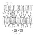
- FIGS. 2-10each illustrate a two dimensional representation of various embodiments (not to relative scale) of a repeating pattern useful in the stent of the present invention
- FIG. 11illustrates an ostial stenosis to which a preferred embodiment of the invention may be applied.
- FIGS. 12 a - 12 iillustrate various embodiments of flexure means (in two dimensions) which may be disposed in the longitudinal struts of preferred embodiments of the present stent.
- Stent 10comprises a proximal end 15 and a distal end 20 .
- Stentfurther comprises a tubular wall 25 disposed between proximal end 15 and distal end 20 .
- tubular wall 25is porous.
- the porosity of tubular wall 25is defined by a plurality of intersecting members 30 .
- Intersecting members 30define a first repeating pattern designated A in FIG. 1 .
- repeating pattern Ais a polygon comprising a pair of side walls 35 , 40 .
- Side walls 35 , 40are substantially parallel to a longitudinal axis 45 of stent 10 and thus side walls 35 , 40 may be considered to be longitudinal struts (indeed with reference to each of the drawings, side walls may also be considered to be longitudinal struts).
- Side walls 35 , 40are connected by a concave-shaped wall 50 and a convex-shaped wall 60 .
- concave-shaped wall 50is made up of a trio of segments 52 , 54 , 56 .
- segment 54is the apex of concave-shaped wall 54 .
- segment 54is a flat apex and results in the provision of a pair of substantially square shoulders 57 , 58 .
- Convex-shaped wall 60is made up of a trio of segments 62 , 64 , 66 .
- segment 64is the apex of convex-shaped wall 60 .
- first repeating pattern Anecessarily defines and provides for a second repeating pattern B.
- second repeating pattern Bis a mirror image of first repeating pattern A taken along an axis (not shown) substantially normal to longitudinal axis 45 .
- adjacent rows of repeating pattern A and repeating pattern Bmay be considered to by interlocking polygons or “arrowheads”.
- concave-shaped wall 50 and/or convex-shaped wall 60can be modified without departing from the function and performance of the stent provided that at least one of concave-shaped wall 50 and convex-shaped wall 60 retain a substantially flat apex.
- the trio of segmentscan be replaced by a suitably curved or arcuate wall.
- more than three segmentscan be used to define concave-shaped wall 50 and/or convex-shaped wall 60 .
- Other modificationswill be apparent to those of skill in the art.
- first repeating pattern A and second repeating pattern Bmay be omitted (and even desired) at selected points along the body of the stent without departing from the spirit and scope of the invention.
- the stent depicted in FIG. 1can be modified to omit, on a selected basis, first repeating pattern A and/or second repeating B with a view to improve flexibility of the stent and to allow access to other structures (e.g. side branches/arteries) outside the bounds of the stent.
- first repeating pattern A and/or second repeating Bwith a view to improve flexibility of the stent and to allow access to other structures (e.g. side branches/arteries) outside the bounds of the stent.
- FIGS. 2-10there are illustrated a number of preferred embodiments of repeating pattern A.
- numerals in FIGS. 2-8have the same final two digits as the corresponding numerals in FIG. 1 .
- the concave-shaped wallis depicted as element 50 in FIG. 1, element 150 in FIG. 2, element 250 in FIG. 3, etc.
- repeating pattern Ais comprised of a concave-shaped wall 150 and a convex-shaped wall 160 , the former having a flat apex.
- concave-shaped wall 150 and convex-shaped wall 160are not equidistant along an axis orthogonal to the longitudinal axis of the stent (not shown).
- the flat apex in concave-shaped wall 150has been modified such that it comprises a pair of substantially rounded shoulders 157 , 158 .
- repeating pattern Ais similar to the one illustrated in FIG. 1 .
- the flat apex of concave-shaped wall 250has been modified to provide a pair of rounded shoulders 257 , 258 .
- a strut 270has been added to connect segment 254 of concave-shaped wall 250 and segment 264 of convex-shaped wall 260 .
- strut 270is thinner in dimension that any of the segments making up concave-shaped wall 250 and convex-shaped wall 260 .
- strut 270may be considered as a relatively thin retention wire which reconciles the need for retaining flexibility in the strut with mitigating lifting of rounded shoulders 257 , 258 when the stent is delivered to the target body passageway through a relatively tortuous route.
- repeating pattern Ais similar to the one illustrated in FIG. 1 .
- the flat apex of concave-shaped wall 350has been modified to provide a pair of rounded shoulders 357 , 358 .
- a curved strut 370has been added to connect segment 354 of concave-shaped wall 350 and segment 364 of convex-shaped wall 360 .
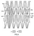
- repeating pattern Ais similar to the one illustrated in FIG. 1 .
- the flat apex of concave-shaped wall 450has been modified to provide a pair of rounded shoulders 457 , 458 .
- a curved strut 470has been added to connect segment 454 of concave-shaped wall 450 and segment 464 of convex-shaped wall 460 .
- side walls 435 , 440are also curved. As discussed above, since side walls 435 , 440 are bowed in opposite directions in adjacent rows of repeating pattern A and B, substantially diametric side walls in adjacent rows will function as the flexure means described above.
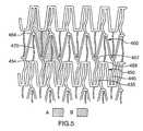
- repeating pattern Ais similar to the one illustrated in FIG. 1 .
- concave-shaped wall 550has been modified to have a flat apex 554 having a pair of rounded shoulders 557 , 558 and convex-shaped wall 560 has been modified also to have a flat apex 564 having a pair of rounded shoulders 567 , 568 .
- a curved strut 570has been added to connect flat apex 554 of concave-shaped wall 550 and flat apex 564 of convex-shaped wall 560 .
- side walls 535 , 540are also curved.
- repeating pattern Ais similar to the one illustrated in FIG. 1 .
- concave-shaped wall 650has been modified to have a flat apex 654 having a pair of rounded shoulders 657 , 658 and convex-shaped wall 660 has been modified also to have a flat apex 664 having a pair of rounded shoulders 667 , 668 .
- a curved strut 670has been added to connect flat apex 654 of concave-shaped wall 650 and flat apex 664 of convex-shaped wall 660 .
- side walls 635 , 640are also curved.
- walls 661 , 662 which connect flat apex 664 to side walls 635 . 640 , respectively, and walls 651 , 652 which connect flat apex 654 to side walls 635 , 640 , respectively,are each curved. It is believed that this design even further enhances the lateral flexibility of the stent.
- repeating pattern Ais similar to the one illustrated in FIG. 1 .
- concave-shaped wall 750has been modified to have a flat apex 754 having a pair of rounded shoulders 757 , 758 and convex-shaped wall 760 has been modified also to have a flat apex 764 having a pair of rounded shoulders 767 , 768 .
- a strut 770has been added to connect flat apex 754 of concave-shaped wall 750 and flax apex 764 of convex-shaped wall 760 .
- side walls 735 , 740have been modified to include a sinusoidal (or S-shaped) portion 736 , 741 , respectively, adjacent convex-shaped wall 760 .
- strut 770has been modified to include a sinusoidal (or S-shaped) portion 771 adjacent flat apex of concave-shaped wall 750 . This design even further enhances the lateral flexibility of the stent.
- repeating pattern Ais similar to the one illustrated in FIG. 1 .
- concave-shaped wall 850has been modified to have a flat apex 854 having a pair of rounded shoulders 857 , 858 .
- side walls 835 , 840have been modified to include a pair of sinusoidal (or S-shaped) portions 836 , 841 , respectively, adjacent convex-shaped wall 860 .
- This designfurther enhances the lateral flexibility of the stent illustrated in FIG. 2 . It should be noted that each sinusoidal (or S-shaped) portion 836 , 841 in FIG.
- each curved sectionhas an arc of greater than 180°—another way to conceptualize this is a pair of link omega-shaped sections (cf. with the curved sections of sinusoidal (or S-shaped) portions 736 , 741 , 771 in FIG. 8 ).
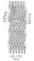
- repeating pattern Ais similar to the one illustrated in FIG. 1 .
- concave-shaped wall 950has been modified to have a flat apex 954 having a pair of rounded shoulders 957 , 958 .
- a strut 970has been added to connect flat-apex 954 of concave-shaped wall 950 and segment 964 of convex-shaped wall 960 .
- side walls 935 , 940have been modified to include a pair of sinusoidal (or S-shaped) portions 936 , 941 , respectively, adjacent convex-shaped wall 960 .
- strut 970has been modified to include sinusoidal (or S-shaped) portion 971 adjacent flat apex of concave-shaped wall 950 .
- each sinusoidal (or S-shaped) portion 936 , 941 , 971 in FIG. 10comprises a pair of adjoined curved sections wherein each curved section has an arc of greater than 180°.
- the curved sections in sinusoidal (or S-shaped) portions 936 , 941are of the same size, whereas the curved sections in sinusoidal (or S-shaped) portion 971 are of different size.
- a distinct advantage of the interspersion of sinusoidal (or S-shaped) portions 936 , 941 and sinusoidal (or S-shaped) portion 971is that substantially uniform radial expansion of all segments in this stent will occur without specific regard to the expansion forces generated by the balloon or other means used to deploy the stent. Further, this design minimizes the force (e.g. pressure from a balloon) required to expand the stent. Still further, this design enhances the lateral flexibility of the stent.
- sinusoidal (or S-shaped) portion 971is offset with respect to sinusoidal (or S-shaped) portions 936 , 941 in a panel horizontal to the longitudinal axis of repeating pattern A.
- the offset nature of these sinusoidal (or S-shaped) portionsserves to increase the bending points in the stent allowing the stent to bend while avoiding buckling thereof.
- the staged distribution of the sinusoidal (or S-shaped) portions over a large portion of the surface area of the stentserves to improve the flexibility of the stent.
- flexure meanssuch as the sinusoidal (or S-shaped) portions in the design of the stents illustrated in FIGS. 8-10, in the longitudinal struts in the stent design provides the added benefit of improved flexibility of the stent in the unexpanded state.
- provision of such a featureallows the inner stent surface adjacent the bend to compress while concurrently allowing the outer stent surface adjacent the bend to extend, all while maintain substantially intact the integral strength of stent and avoiding buckling of the stent.
- FIGS. 12 a - 12 ithere are illustrated various alternatives of bowed lateral sections which can be used in place of sinusoidal (or S-shaped) portions 736 , 741 , 771 in FIG. 8, sinusoidal (or S-shaped) portions 836 , 841 in FIG. 9 and sinusoidal (or S-shaped) portions 936 , 941 , 971 in FIG. 10 .
- the flexure means illustrated in FIG. 12 amay be considered to be an asymmetric zig-zag whereas that illustrated in FIG. 12 b may be considered to be a symmetric zig-zag and that illustrated in FIG.
- the flexure means illustrated in FIG. 12 dmay be considered to be a single omega, whereas that illustrated in FIG. 12 e may be considered to be an inline (and unlinked) double omega and that illustrated in FIG. 12 f may be considered to be an opposed (and unlinked) double omega.
- the flexure means illustrated in FIG. 12 gmay be considered to be an opposed omega (facilitates extension)/U-joint (facilitates compression). Still further the flexure means illustrated in FIG. 12 h may be considered to be a rail flex whereas that illustrated in FIG. 12 i may be considered to be an opposed rail flex.
- Other specific designs which are with the spirit and scope of the present inventionwill be apparent to those of skill in the art.
- FIGS. 2-10 and 12a preferred embodiment of the present invention involves combining various of the repeating patterns illustrated in FIGS. 2-10 to achieve a stent with relatively flexible and rigid regions, for example, as follows:
- an embodiment of the inventionis a stent comprising a first section incorporating the design of FIG. 10 and a second section incorporating the design of FIG. 9 . It is believed that such a multi-sectional design provides a very desirable combination of lateral flexibility (primarily from the design of FIG. 9) with post-expansion radial rigidity (primarily from the design of FIG. 10 ).
- the relative flexibility/rigiditymay be varied along the length of the stent.
- the thickness of the segmentsmay be varied in the range of from about 0.0015 to about 0.0045 inches, preferably from about 0.0020 to about 0.0040 inches. The lower the thickness in this range, the more flexible the resulting stent design. Conversely, the higher the thickness in this range, the less flexible the resulting stent design.
- the relative flexibility/rigidity of the stentmay be varied along its length.
- a stent with a variable relative flexibility/rigidity along its lengthis believed to be novel, especially a stent comprising a single relatively flexible portion and a single relatively rigid portion (i.e. the F-R embodiment discussed above).
- a stentwould find immediate use in a number of applications.
- such a stentwould very desirable for implantation in an ostial stenosis (these typically occur in coronary arteries, vein grafts and renal arteries).
- an ostial stenosisis illustrated in FIG. 11 thereof.
- FIG. 11there is illustrated a right coronary cusp 105 , a right coronary artery 110 and an ostial segment 115 of right coronary artery 110 .
- a stenosis 120presents a narrowing of ostial segment 115 .
- a stent capable of implantation into such an ostial stenosismust be of sufficient rigidity after expansion to resist the elastic recoil of the ostial blockage (Region Y in FIG. 11 ).
- a stent of such sufficient rigiditywill be deficient since it will either: (i) be retarded in its advance along the artery due to the sharp bend in the right coronary artery (Region X in FIG. 11 ); or (ii) traverse the sharp bend in the right coronary artery but subsequently straighten Region X of right coronary artery 110 thereby increasing the likelihood of tearing the artery.
- FIG. 11also serves to illustrated the substantially complementary extension and compression of longitudinal members in Region X of the right coronary artery.
- the stentis produced by laser cutting techniques applied to a tubular starting material.
- the starting materialcould be a thin tube of a metal or alloy (non-limiting examples include stainless steel, titanium, tantalum, nitinol, Elgiloy, NP35SN and mixtures thereof) which would then have sections thereof cut out to leave repeating pattern A discussed above.
- the preferred design of the present stentis one of a tubular wall which is distinct from prior art wire mesh designs wherein wire is conformed to the desired shape and welded in place.
- the preferred tubular wall design of the present stentfacilitates production and improves quality control by avoiding the use of welds and, instead, utilizing specific cutting techniques.
- the stentis coated with a solution of 1:2 (mole) copolymer of (methacryloyloxy ethyl)-2-(trimethylammonium ethyl) phosphate inner salt with lauryl methacrylate in ethanol (as described in Example 2 of International patent application WO-A-93/01221) as follows.
- the non-expanded stentmay be placed in a tube having a slightly larger diameter than the stent.
- the tubemay then be filled with coating solution and the solution allowed to drain steadily from the tube to form a completely coated stent.
- a stream of warm air or nitrogenmay be directed through the tube at a linear velocity of 0.1.5 m/s at room temperature to 50° C. for a period of 30 seconds to 5 minutes to dry the coating by evaporation of the ethanol solvent.
- a cross-linkable coatingmay be used consisting of a polymer of 23 mole % (methacryloyloxy ethyl)-2-(trimethylammonium ethyl) phosphate inner salt, 47 mole % lauryl methacrylate, 5 mole % ⁇ trimethoxysilylpropyl methacrylate and 25 mole % of ⁇ hydroxypropyl methacrylate.
- Thismay be applied to the sent by the above described technique from a 5 mg/ml ethanoic solution.
- the solutionmay be dried as described above and then cured by heating at 70 to 75° C. for a period of at least about 1 hour, for instance overnight.
- This curinggenerally results in substantially complete reaction of the methoxy silyl groups, either with other methoxylsily groups or with hydroxy groups derived from the hydroxypropyl methacrylate monomer, driving of methanol.
- the crosslinkable coatingis applied to the cleared stent, cured and then a further coating of the lauryl methacrylate copolymer described above is applied.
- the coated stentmay be sterilised by ethylene oxide, gamma radiation or electron beam and subsequently mounted onto a balloon catheter for delivery.
- Stent 10can be implanted using a conventional system wherein a guidewire, catheter and balloon can be used to position and expand the stent.
- Implantation of mono-tubular stents such as stent 10is conventional and within the purview of a person skilled in the art. See, for example, any one of U.S. Pat. Nos. 4,733,665, 4,739,762, 5,035,706, 5,037,392, 5,102,417, 5,147,385, 5,282,824, 5,316,023 and any of the references cited therein or any of the references cited hereinabove.
- the present stentWhen the present stent is constructed as a bifurcated stent, it may be implanted using the procedure outlined in the '997 patent application incorporated herein by reference.
- a bifurcated stentmay be manufactured, inter alia, by any of the methods disclosed in the Canadian patent application number 2,175,720 filed in Applicant's name on May 3, 1996, the contents of which are hereby incorporated by reference.
- the stentcan be made of a suitable material which will expand when a certain temperature is reached.
- the materialmay be a metal alloy (e.g. nitinol) capable of self-expansion at a temperature of at least about 30° C., preferably in the range of from about 30° to about 40° C.
- the stentcould be implanted using a conventional catheter and the radially outward force exerted on the stent would be generated within the stent itself.
- stent 10can be designed to expand upon the application of mechanical forces other than those applied by a balloon/catheter.
- the stentwould be resiliently compressed and would self-expanded once the compressive force (i.e. provided by the sleeve or membrane) is removed.
- repeating pattern Ahas been described hereinabove and illustrated in FIG. 1 in respect of a monotubular stent.
- Repeating pattern A and all of the features relating thereto illustrated in and described with reference to FIGS. 1-10is equally applicable to a bifurcated stent such as the one described and illustrated in the '997 application discussed hereinabove, the contents of which are hereby incorporated by reference.
Landscapes
- Health & Medical Sciences (AREA)
- Engineering & Computer Science (AREA)
- Biomedical Technology (AREA)
- Heart & Thoracic Surgery (AREA)
- Life Sciences & Earth Sciences (AREA)
- Cardiology (AREA)
- Oral & Maxillofacial Surgery (AREA)
- Transplantation (AREA)
- Veterinary Medicine (AREA)
- Vascular Medicine (AREA)
- Public Health (AREA)
- Animal Behavior & Ethology (AREA)
- General Health & Medical Sciences (AREA)
- Optics & Photonics (AREA)
- Physics & Mathematics (AREA)
- Media Introduction/Drainage Providing Device (AREA)
- Prostheses (AREA)
- Materials For Medical Uses (AREA)
Abstract
Description
Claims (52)
Priority Applications (7)
| Application Number | Priority Date | Filing Date | Title |
|---|---|---|---|
| US09/672,767US6375677B1 (en) | 1996-03-05 | 2000-09-29 | Expandable stent and method for delivery of same |
| US10/073,277US6858037B2 (en) | 1996-03-05 | 2002-02-13 | Expandable stent and method for delivery of same |
| US10/190,818US6881223B2 (en) | 1996-03-05 | 2002-07-09 | Expandable stent and method for delivery of same |
| US10/191,522US6887264B2 (en) | 1996-03-05 | 2002-07-10 | Expandable stent and method for delivery of same |
| US10/761,459US20040153141A1 (en) | 1996-03-05 | 2004-01-22 | Expandable stent and method for delivery of same |
| US11/840,098US20080021536A1 (en) | 1996-03-05 | 2007-08-16 | Expandable stent and method for delivery of same |
| US12/419,453US20090192590A1 (en) | 1996-03-05 | 2009-04-07 | Expandable stent and method for delivery of same |
Applications Claiming Priority (10)
| Application Number | Priority Date | Filing Date | Title |
|---|---|---|---|
| CA 2171047CA2171047A1 (en) | 1996-03-05 | 1996-03-05 | Expandable stent and method for delivery of same |
| CA2171047 | 1996-03-06 | ||
| CA2175722 | 1996-05-03 | ||
| CA 2175722CA2175722A1 (en) | 1996-05-03 | 1996-05-03 | Expandable stent and method for delivery of same |
| CA2185740 | 1996-09-17 | ||
| CA 2185740CA2185740A1 (en) | 1996-09-17 | 1996-09-17 | Expandable stent and method for delivery of same |
| CA2192520 | 1996-12-10 | ||
| CA002192520ACA2192520A1 (en) | 1996-03-05 | 1996-12-10 | Expandable stent and method for delivery of same |
| US09/142,508US6217608B1 (en) | 1996-03-05 | 1997-03-05 | Expandable stent and method for delivery of same |
| US09/672,767US6375677B1 (en) | 1996-03-05 | 2000-09-29 | Expandable stent and method for delivery of same |
Related Parent Applications (3)
| Application Number | Title | Priority Date | Filing Date |
|---|---|---|---|
| US09/142,508ContinuationUS6217608B1 (en) | 1996-03-05 | 1997-03-05 | Expandable stent and method for delivery of same |
| US09142508Continuation | 1997-03-05 | ||
| PCT/CA1997/000151ContinuationWO1997032543A1 (en) | 1996-03-05 | 1997-03-05 | Expandable stent and method for delivery of same |
Related Child Applications (1)
| Application Number | Title | Priority Date | Filing Date |
|---|---|---|---|
| US10/073,277ContinuationUS6858037B2 (en) | 1996-03-05 | 2002-02-13 | Expandable stent and method for delivery of same |
Publications (1)
| Publication Number | Publication Date |
|---|---|
| US6375677B1true US6375677B1 (en) | 2002-04-23 |
Family
ID=27427270
Family Applications (7)
| Application Number | Title | Priority Date | Filing Date |
|---|---|---|---|
| US09/142,508Expired - Fee RelatedUS6217608B1 (en) | 1996-03-05 | 1997-03-05 | Expandable stent and method for delivery of same |
| US09/142,509Expired - LifetimeUS6183506B1 (en) | 1996-03-05 | 1997-03-05 | Expandable stent and method for delivery of same |
| US09/672,768Expired - Fee RelatedUS6758860B1 (en) | 1996-03-05 | 2000-09-29 | Expandable stent and method for delivery of same |
| US09/672,767Expired - LifetimeUS6375677B1 (en) | 1996-03-05 | 2000-09-29 | Expandable stent and method for delivery of same |
| US11/419,895AbandonedUS20060200228A1 (en) | 1996-03-05 | 2006-05-23 | Expandable Stent And Method For Delivery Of Same |
| US12/252,478AbandonedUS20090036974A1 (en) | 1996-03-05 | 2008-10-16 | Expandable stent and method for delivery of same |
| US12/419,453AbandonedUS20090192590A1 (en) | 1996-03-05 | 2009-04-07 | Expandable stent and method for delivery of same |
Family Applications Before (3)
| Application Number | Title | Priority Date | Filing Date |
|---|---|---|---|
| US09/142,508Expired - Fee RelatedUS6217608B1 (en) | 1996-03-05 | 1997-03-05 | Expandable stent and method for delivery of same |
| US09/142,509Expired - LifetimeUS6183506B1 (en) | 1996-03-05 | 1997-03-05 | Expandable stent and method for delivery of same |
| US09/672,768Expired - Fee RelatedUS6758860B1 (en) | 1996-03-05 | 2000-09-29 | Expandable stent and method for delivery of same |
Family Applications After (3)
| Application Number | Title | Priority Date | Filing Date |
|---|---|---|---|
| US11/419,895AbandonedUS20060200228A1 (en) | 1996-03-05 | 2006-05-23 | Expandable Stent And Method For Delivery Of Same |
| US12/252,478AbandonedUS20090036974A1 (en) | 1996-03-05 | 2008-10-16 | Expandable stent and method for delivery of same |
| US12/419,453AbandonedUS20090192590A1 (en) | 1996-03-05 | 2009-04-07 | Expandable stent and method for delivery of same |
Country Status (10)
| Country | Link |
|---|---|
| US (7) | US6217608B1 (en) |
| EP (3) | EP0888094B1 (en) |
| JP (5) | JP4281851B2 (en) |
| AT (5) | ATE471127T1 (en) |
| AU (3) | AU1864497A (en) |
| CA (2) | CA2192520A1 (en) |
| DE (5) | DE69705706T3 (en) |
| ID (1) | ID16130A (en) |
| MY (1) | MY130279A (en) |
| WO (1) | WO1997032543A1 (en) |
Cited By (60)
| Publication number | Priority date | Publication date | Assignee | Title |
|---|---|---|---|---|
| US20020022877A1 (en)* | 2000-03-15 | 2002-02-21 | Biotronik Mess-Und Therapiegeraete Gmbh & Co. | Stent |
| US20020095208A1 (en)* | 2000-09-22 | 2002-07-18 | Scimed Life Systems, Inc. | Stent |
| US20020116049A1 (en)* | 2000-09-22 | 2002-08-22 | Scimed Life Systems, Inc. | Stent |
| US20020138131A1 (en)* | 2001-03-20 | 2002-09-26 | Solovay Kenneth S. | Rail stent |
| US20030045925A1 (en)* | 2001-08-29 | 2003-03-06 | Swaminathan Jayaraman | Structurally variable stents |
| US6562067B2 (en)* | 2001-06-08 | 2003-05-13 | Cordis Corporation | Stent with interlocking elements |
| US6605110B2 (en)* | 2001-06-29 | 2003-08-12 | Advanced Cardiovascular Systems, Inc. | Stent with enhanced bendability and flexibility |
| US6607554B2 (en)* | 2001-06-29 | 2003-08-19 | Advanced Cardiovascular Systems, Inc. | Universal stent link design |
| US6616689B1 (en) | 2000-05-03 | 2003-09-09 | Advanced Cardiovascular Systems, Inc. | Intravascular stent |
| US6629994B2 (en) | 2001-06-11 | 2003-10-07 | Advanced Cardiovascular Systems, Inc. | Intravascular stent |
| US6656220B1 (en)* | 2002-06-17 | 2003-12-02 | Advanced Cardiovascular Systems, Inc. | Intravascular stent |
| WO2004010902A1 (en)* | 2002-07-31 | 2004-02-05 | Unison Therapeutics, Inc. | Flexible and conformable stent and method of forming same |
| US20040106975A1 (en)* | 2001-03-20 | 2004-06-03 | Gmp/Cardiac Care, Inc. | Rail stent |
| US20040106980A1 (en)* | 2002-08-15 | 2004-06-03 | Gmp Cardiac Care, Inc. | Stent-graft with rails |
| US20040122511A1 (en)* | 2002-11-05 | 2004-06-24 | Mangiardi Eric K. | Coated stent with geometry determinated functionality and method of making the same |
| US6758860B1 (en) | 1996-03-05 | 2004-07-06 | Envysio Medical Devices Ulc | Expandable stent and method for delivery of same |
| US6786922B2 (en) | 2002-10-08 | 2004-09-07 | Cook Incorporated | Stent with ring architecture and axially displaced connector segments |
| US6796997B1 (en) | 1996-03-05 | 2004-09-28 | Evysio Medical Devices Ulc | Expandable stent |
| US20040236404A1 (en)* | 1996-03-05 | 2004-11-25 | Penn Ian M. | Expandable stent and method for delivery of same |
| US6846323B2 (en) | 2003-05-15 | 2005-01-25 | Advanced Cardiovascular Systems, Inc. | Intravascular stent |
| US20050090888A1 (en)* | 2003-10-28 | 2005-04-28 | Hines Richard A. | Pleated stent assembly |
| US20060004437A1 (en)* | 2001-08-29 | 2006-01-05 | Swaminathan Jayaraman | Structurally variable stents |
| US20060020322A1 (en)* | 2004-07-21 | 2006-01-26 | Alexander Leynov | Expandable framework with overlapping connectors |
| US20060100695A1 (en)* | 2002-09-27 | 2006-05-11 | Peacock James C Iii | Implantable stent with modified ends |
| US7044963B1 (en)* | 1996-09-19 | 2006-05-16 | Medinol, Ltd. | Stent with variable features to optimize support and method of making such stent |
| US20060173531A1 (en)* | 1996-09-19 | 2006-08-03 | Jacob Richter | Stent with variable features to optimize support and method of making such stent |
| US20060258972A1 (en)* | 2005-05-13 | 2006-11-16 | Alveolus, Inc. | Delivery device with viewing window and associated method |
| US20070005126A1 (en)* | 2005-06-30 | 2007-01-04 | Boston Scientific Scimed, Inc. | Hybrid stent |
| US20070150049A1 (en)* | 2004-03-16 | 2007-06-28 | Alveolus, Inc. | Stent |
| US20070173921A1 (en)* | 2005-10-28 | 2007-07-26 | Wholey Mark H | Flared stents and apparatus and methods for delivering them |
| US7252680B2 (en) | 2001-04-18 | 2007-08-07 | Alveolus, Inc. | Removable essentially cylindrical implants |
| US20070191926A1 (en)* | 2006-02-14 | 2007-08-16 | Advanced Cardiovascular Systems, Inc. | Stent pattern for high stent retention |
| KR100778020B1 (en) | 2005-10-24 | 2007-11-28 | 사회복지법인 삼성생명공익재단 | Vascular stents for multiple drug loading and more effective drug release |
| US20080051879A1 (en)* | 2006-08-23 | 2008-02-28 | Cook Incorporated | Methods of treating venous valve related conditions with a flow-modifying implantable medical device |
| US20080086194A1 (en)* | 2006-10-06 | 2008-04-10 | Advanced Cardiovascular Systems, | Intravascular stent |
| US20080109068A1 (en)* | 2000-09-22 | 2008-05-08 | Fischell Robert E | Stent with optimal strength and radiopacity characteristics |
| US20080132998A1 (en)* | 2004-09-29 | 2008-06-05 | Alveolus, Inc. | Active stent |
| US20080133000A1 (en)* | 2006-12-01 | 2008-06-05 | Medtronic Vascular, Inc. | Bifurcated Stent With Variable Length Branches |
| US20080262601A1 (en)* | 2002-09-13 | 2008-10-23 | Cully Edward H | Stent Device with Multiple Helix Construction |
| US7527644B2 (en) | 2002-11-05 | 2009-05-05 | Alveolus Inc. | Stent with geometry determinated functionality and method of making the same |
| US7547321B2 (en) | 2001-07-26 | 2009-06-16 | Alveolus Inc. | Removable stent and method of using the same |
| USRE40816E1 (en) | 1995-11-01 | 2009-06-30 | Biocompatibles Uk Limited | Biocompatible crosslinked coating and crosslinkable coating polymer composition for forming such a coating |
| US20090192589A1 (en)* | 2001-06-11 | 2009-07-30 | Advanced Cardiovascular Systems, Inc. | Intravascular stent |
| US20100152836A1 (en)* | 2000-03-06 | 2010-06-17 | Boston Scientific Scimed, Inc. | Intraluminar perforated radially expandable drug delivery prosthesis and a method for the production thereof |
| US7875068B2 (en) | 2002-11-05 | 2011-01-25 | Merit Medical Systems, Inc. | Removable biliary stent |
| US7959671B2 (en) | 2002-11-05 | 2011-06-14 | Merit Medical Systems, Inc. | Differential covering and coating methods |
| US8328863B2 (en) | 2010-04-22 | 2012-12-11 | Abbott Cardiovascular Systems Inc. | Optimal ratio of polar and bending moment of inertia for stent strut design |
| US8449597B2 (en) | 1995-03-01 | 2013-05-28 | Boston Scientific Scimed, Inc. | Longitudinally flexible expandable stent |
| US8556511B2 (en) | 2010-09-08 | 2013-10-15 | Abbott Cardiovascular Systems, Inc. | Fluid bearing to support stent tubing during laser cutting |
| WO2014176361A1 (en)* | 2013-04-25 | 2014-10-30 | Reva Medical, Inc. | Expandable deformable slide and lock stent |
| US9066827B2 (en) | 2008-10-10 | 2015-06-30 | Reva Medical, Inc. | Expandable slide and lock stent |
| US9173751B2 (en) | 2004-12-17 | 2015-11-03 | Reva Medical, Inc. | Slide-and-lock stent |
| US9314354B2 (en) | 2007-11-30 | 2016-04-19 | Reva Medical, Inc. | Axially-radially nested expandable device |
| US9408732B2 (en) | 2013-03-14 | 2016-08-09 | Reva Medical, Inc. | Reduced-profile slide and lock stent |
| US9452068B2 (en) | 2010-04-10 | 2016-09-27 | Reva Medical, Inc. | Expandable slide and lock stent |
| US9907640B2 (en) | 2013-06-21 | 2018-03-06 | Boston Scientific Scimed, Inc. | Stent with deflecting connector |
| US10238513B2 (en) | 2017-07-19 | 2019-03-26 | Abbott Cardiovascular Systems Inc. | Intravascular stent |
| EP4148316A1 (en)* | 2019-02-19 | 2023-03-15 | Mueller International, LLC | Stent springs and stents for repairing pipes |
| US11802646B2 (en) | 2019-08-09 | 2023-10-31 | Mueller International, Llc | Pipe repair device |
| US20240180728A1 (en)* | 2014-07-17 | 2024-06-06 | W. L. Gore & Associates, Inc. | Stent having adjacent elements connected by narrow flexible webs |
Families Citing this family (263)
| Publication number | Priority date | Publication date | Assignee | Title |
|---|---|---|---|---|
| US6743878B2 (en)* | 1991-07-05 | 2004-06-01 | Biocompatibles Uk Limited | Polymeric surface coatings |
| CA2079417C (en)* | 1991-10-28 | 2003-01-07 | Lilip Lau | Expandable stents and method of making same |
| US6896696B2 (en) | 1998-11-20 | 2005-05-24 | Scimed Life Systems, Inc. | Flexible and expandable stent |
| US6602281B1 (en)* | 1995-06-05 | 2003-08-05 | Avantec Vascular Corporation | Radially expansible vessel scaffold having beams and expansion joints |
| US6287336B1 (en) | 1995-10-16 | 2001-09-11 | Medtronic, Inc. | Variable flexibility stent |
| US20040106985A1 (en) | 1996-04-26 | 2004-06-03 | Jang G. David | Intravascular stent |
| US6241760B1 (en)* | 1996-04-26 | 2001-06-05 | G. David Jang | Intravascular stent |
| US5954743A (en)* | 1996-04-26 | 1999-09-21 | Jang; G. David | Intravascular stent |
| US6235053B1 (en)* | 1998-02-02 | 2001-05-22 | G. David Jang | Tubular stent consists of chevron-shape expansion struts and contralaterally attached diagonal connectors |
| JP4636634B2 (en)* | 1996-04-26 | 2011-02-23 | ボストン サイエンティフィック サイムド,インコーポレイテッド | Intravascular stent |
| US7591846B2 (en) | 1996-11-04 | 2009-09-22 | Boston Scientific Scimed, Inc. | Methods for deploying stents in bifurcations |
| US7220275B2 (en) | 1996-11-04 | 2007-05-22 | Advanced Stent Technologies, Inc. | Stent with protruding branch portion for bifurcated vessels |
| US6835203B1 (en) | 1996-11-04 | 2004-12-28 | Advanced Stent Technologies, Inc. | Extendible stent apparatus |
| US6692483B2 (en) | 1996-11-04 | 2004-02-17 | Advanced Stent Technologies, Inc. | Catheter with attached flexible side sheath |
| EP1723931B1 (en) | 1996-11-04 | 2012-01-04 | Advanced Stent Technologies, Inc. | Extendible stent apparatus and method for deploying the same |
| US6599316B2 (en) | 1996-11-04 | 2003-07-29 | Advanced Stent Technologies, Inc. | Extendible stent apparatus |
| US7341598B2 (en) | 1999-01-13 | 2008-03-11 | Boston Scientific Scimed, Inc. | Stent with protruding branch portion for bifurcated vessels |
| US8211167B2 (en) | 1999-12-06 | 2012-07-03 | Boston Scientific Scimed, Inc. | Method of using a catheter with attached flexible side sheath |
| US6325826B1 (en) | 1998-01-14 | 2001-12-04 | Advanced Stent Technologies, Inc. | Extendible stent apparatus |
| DE69735711T3 (en)* | 1996-11-07 | 2010-07-01 | Medtronic Instent Inc., Eden Prairie | Stent with variable flexibility |
| EP0953001A1 (en)* | 1997-01-10 | 1999-11-03 | Biocompatibles Limited | Polymers |
| US5827321A (en)* | 1997-02-07 | 1998-10-27 | Cornerstone Devices, Inc. | Non-Foreshortening intraluminal prosthesis |
| DE29702671U1 (en)* | 1997-02-17 | 1997-04-10 | Jomed Implantate GmbH, 72414 Rangendingen | Stent |
| CA2214627A1 (en)* | 1997-03-05 | 1998-09-05 | Divysio Solutions Ulc | Expandable stent |
| IL128261A0 (en) | 1999-01-27 | 1999-11-30 | Disc O Tech Medical Tech Ltd | Expandable element |
| WO2004110300A2 (en)* | 2001-07-25 | 2004-12-23 | Disc Orthopaedic Technologies Inc. | Deformable tools and implants |
| US6033433A (en) | 1997-04-25 | 2000-03-07 | Scimed Life Systems, Inc. | Stent configurations including spirals |
| FR2762777B1 (en)* | 1997-05-05 | 1999-10-22 | Patrick Sabaria | VASCULAR AND CORONARY EXTENDERS, USUALLY DESIGNATED UNDER THE NAME OF "STENT" |
| ATE336958T1 (en)* | 1997-05-07 | 2006-09-15 | Cordis Corp | INTRAVASCULAR STENT AND SYSTEM FOR INSERTING (OBSTRUCTION OF THE OSTIUM OF A VESSEL) |
| DE29708879U1 (en)* | 1997-05-20 | 1997-07-31 | Jomed Implantate GmbH, 72414 Rangendingen | Coronary stent |
| US5836966A (en) | 1997-05-22 | 1998-11-17 | Scimed Life Systems, Inc. | Variable expansion force stent |
| DE19722384A1 (en)* | 1997-05-28 | 1998-12-03 | Gfe Ges Fuer Forschung Und Ent | Flexible expandable stent |
| US6165195A (en)* | 1997-08-13 | 2000-12-26 | Advanced Cardiovascylar Systems, Inc. | Stent and catheter assembly and method for treating bifurcations |
| US7753950B2 (en)* | 1997-08-13 | 2010-07-13 | Advanced Cardiovascular Systems, Inc. | Stent and catheter assembly and method for treating bifurcations |
| FR2768919B1 (en)* | 1997-10-01 | 1999-11-19 | Braun Celsa Sa | EXPANDABLE SUPPORT FOR ANATOMICAL DUCT |
| US6071308A (en) | 1997-10-01 | 2000-06-06 | Boston Scientific Corporation | Flexible metal wire stent |
| US6013091A (en) | 1997-10-09 | 2000-01-11 | Scimed Life Systems, Inc. | Stent configurations |
| US6309414B1 (en)* | 1997-11-04 | 2001-10-30 | Sorin Biomedica Cardio S.P.A. | Angioplasty stents |
| US6330884B1 (en)* | 1997-11-14 | 2001-12-18 | Transvascular, Inc. | Deformable scaffolding multicellular stent |
| FR2771921B1 (en)* | 1997-12-09 | 2000-03-24 | Jean Marie Lefebvre | STAINLESS STEEL STENT TO BE IMPLANTED IN A VASCULAR CONDUIT USING AN INFLATABLE BALLOON |
| AU2579999A (en)* | 1998-02-03 | 1999-08-16 | Cardiovascular Interventional Systems, Inc. | Tubular stent consists of non-parallel expansion struts and contralaterally attached diagonal connectors |
| US6113627A (en)* | 1998-02-03 | 2000-09-05 | Jang; G. David | Tubular stent consists of horizontal expansion struts and contralaterally attached diagonal-connectors |
| US6395019B2 (en) | 1998-02-09 | 2002-05-28 | Trivascular, Inc. | Endovascular graft |
| DE69929036T2 (en) | 1998-02-12 | 2006-08-31 | Thomas R. North Vancouver Marotta | ENDOVASCULAR PROSTHESIS |
| AU2684499A (en)* | 1998-02-17 | 1999-08-30 | G. David Jang | Tubular stent consists of chevron-shape expansion struts and ipsilaterally attached m-frame connectors |
| DK174814B1 (en)* | 1998-02-25 | 2003-12-01 | Cook William Europ | stent device |
| WO1999044543A1 (en) | 1998-03-04 | 1999-09-10 | Scimed Life Systems, Inc. | Improved stent cell configurations |
| US6019789A (en)* | 1998-04-01 | 2000-02-01 | Quanam Medical Corporation | Expandable unit cell and intraluminal stent |
| FR2777771B1 (en) | 1998-04-27 | 2000-08-25 | Microval | TUBULAR AND FLEXIBLE VASCULAR ENDOPROSTHESIS |
| US6066169A (en)* | 1998-06-02 | 2000-05-23 | Ave Connaught | Expandable stent having articulated connecting rods |
| US6261319B1 (en) | 1998-07-08 | 2001-07-17 | Scimed Life Systems, Inc. | Stent |
| NZ510187A (en) | 1998-07-31 | 2003-08-29 | Novo Rps Ulc | Small vessel expandable stent and method for production of same |
| US6193744B1 (en) | 1998-09-10 | 2001-02-27 | Scimed Life Systems, Inc. | Stent configurations |
| US7662409B2 (en) | 1998-09-25 | 2010-02-16 | Gel-Del Technologies, Inc. | Protein matrix materials, devices and methods of making and using thereof |
| EP1126795A2 (en)* | 1998-11-06 | 2001-08-29 | St. Jude Medical Cardiovascular Group, Inc. | Medical graft connector component and methods of making and installing same |
| US6190403B1 (en) | 1998-11-13 | 2001-02-20 | Cordis Corporation | Low profile radiopaque stent with increased longitudinal flexibility and radial rigidity |
| WO2000035378A1 (en)* | 1998-12-18 | 2000-06-22 | Cook Incorporated | Cannula stent |
| US20050060027A1 (en)* | 1999-01-13 | 2005-03-17 | Advanced Stent Technologies, Inc. | Catheter balloon systems and methods |
| US7655030B2 (en) | 2003-07-18 | 2010-02-02 | Boston Scientific Scimed, Inc. | Catheter balloon systems and methods |
| US7621950B1 (en) | 1999-01-27 | 2009-11-24 | Kyphon Sarl | Expandable intervertebral spacer |
| AU2529600A (en) | 1999-02-12 | 2000-08-29 | Novo Rps Ulc | Endovascular prosthesis |
| US7029492B1 (en)* | 1999-03-05 | 2006-04-18 | Terumo Kabushiki Kaisha | Implanting stent and dilating device |
| US6273911B1 (en) | 1999-04-22 | 2001-08-14 | Advanced Cardiovascular Systems, Inc. | Variable strength stent |
| US6375676B1 (en)* | 1999-05-17 | 2002-04-23 | Advanced Cardiovascular Systems, Inc. | Self-expanding stent with enhanced delivery precision and stent delivery system |
| JP4799738B2 (en)* | 1999-05-19 | 2011-10-26 | ノイス,マルテ | Radially expandable tube support |
| US6884258B2 (en) | 1999-06-04 | 2005-04-26 | Advanced Stent Technologies, Inc. | Bifurcation lesion stent delivery using multiple guidewires |
| US7387639B2 (en)* | 1999-06-04 | 2008-06-17 | Advanced Stent Technologies, Inc. | Short sleeve stent delivery catheter and methods |
| US20060216313A1 (en)* | 1999-08-10 | 2006-09-28 | Allergan, Inc. | Methods for treating a stricture with a botulinum toxin |
| US6767544B2 (en)* | 2002-04-01 | 2004-07-27 | Allergan, Inc. | Methods for treating cardiovascular diseases with botulinum toxin |
| US6689156B1 (en)* | 1999-09-23 | 2004-02-10 | Advanced Stent Technologies, Inc. | Stent range transducers and methods of use |
| DE19951607A1 (en)* | 1999-10-26 | 2001-05-10 | Biotronik Mess & Therapieg | Stent with a closed structure |
| US6428569B1 (en)* | 1999-11-09 | 2002-08-06 | Scimed Life Systems Inc. | Micro structure stent configurations |
| CA2404092A1 (en) | 2000-04-11 | 2001-10-18 | James Teague | Reinforced retention structures |
| US6602282B1 (en)* | 2000-05-04 | 2003-08-05 | Avantec Vascular Corporation | Flexible stent structure |
| US6805704B1 (en) | 2000-06-26 | 2004-10-19 | C. R. Bard, Inc. | Intraluminal stents |
| US7766956B2 (en)* | 2000-09-22 | 2010-08-03 | Boston Scientific Scimed, Inc. | Intravascular stent and assembly |
| US6626935B1 (en)* | 2000-12-21 | 2003-09-30 | Advanced Cardiovascular Systems, Inc. | Intravascular stent |
| US6929660B1 (en)* | 2000-12-22 | 2005-08-16 | Advanced Cardiovascular Systems, Inc. | Intravascular stent |
| WO2002054989A2 (en)* | 2001-01-15 | 2002-07-18 | Terumo Corp | Stent |
| US6679911B2 (en) | 2001-03-01 | 2004-01-20 | Cordis Corporation | Flexible stent |
| US6740114B2 (en) | 2001-03-01 | 2004-05-25 | Cordis Corporation | Flexible stent |
| US6790227B2 (en)* | 2001-03-01 | 2004-09-14 | Cordis Corporation | Flexible stent |
| US6998060B2 (en) | 2001-03-01 | 2006-02-14 | Cordis Corporation | Flexible stent and method of manufacture |
| AU784552B2 (en) | 2001-03-02 | 2006-05-04 | Cardinal Health 529, Llc | Flexible stent |
| US10105209B2 (en) | 2001-04-11 | 2018-10-23 | Andrew Kerr | Stent/graft assembly |
| US8617231B2 (en) | 2001-05-18 | 2013-12-31 | Boston Scientific Scimed, Inc. | Dual guidewire exchange catheter system |
| US6635083B1 (en) | 2001-06-25 | 2003-10-21 | Advanced Cardiovascular Systems, Inc. | Stent with non-linear links and method of use |
| US6749629B1 (en) | 2001-06-27 | 2004-06-15 | Advanced Cardiovascular Systems, Inc. | Stent pattern with figure-eights |
| US7520892B1 (en) | 2001-06-28 | 2009-04-21 | Advanced Cardiovascular Systems, Inc. | Low profile stent with flexible link |
| US7252679B2 (en)* | 2001-09-13 | 2007-08-07 | Cordis Corporation | Stent with angulated struts |
| US8262689B2 (en)* | 2001-09-28 | 2012-09-11 | Advanced Cardiovascular Systems, Inc. | Embolic filtering devices |
| US7147661B2 (en)* | 2001-12-20 | 2006-12-12 | Boston Scientific Santa Rosa Corp. | Radially expandable stent |
| JP4331610B2 (en) | 2001-12-20 | 2009-09-16 | トリバスキュラー2,インコーポレイティド | Advanced endovascular graft |
| US20050182477A1 (en)* | 2001-12-20 | 2005-08-18 | White Geoffrey H. | Intraluminal stent and graft |
| US20030135265A1 (en)* | 2002-01-04 | 2003-07-17 | Stinson Jonathan S. | Prostheses implantable in enteral vessels |
| US8623393B2 (en) | 2002-04-29 | 2014-01-07 | Gel-Del Technologies, Inc. | Biomatrix structural containment and fixation systems and methods of use thereof |
| AU2003239369A1 (en)* | 2002-05-06 | 2003-11-17 | Abbott Laboratories | Endoprosthesis for controlled contraction and expansion |
| US7128756B2 (en) | 2002-05-08 | 2006-10-31 | Abbott Laboratories | Endoprosthesis having foot extensions |
| AU2003249309A1 (en)* | 2002-07-24 | 2004-02-09 | Advanced Stent Technologies, Inc. | Stents capable of controllably releasing histone deacetylase inhibitors |
| US20040093068A1 (en)* | 2002-07-24 | 2004-05-13 | Bergen Lee C. | Abdominal stent graft and delivery system |
| US20040093056A1 (en)* | 2002-10-26 | 2004-05-13 | Johnson Lianw M. | Medical appliance delivery apparatus and method of use |
| AU2002368483A1 (en) | 2002-12-19 | 2004-07-14 | Invatec S.R.L. | Endolumenal prosthesis |
| US6896697B1 (en) | 2002-12-30 | 2005-05-24 | Advanced Cardiovascular Systems, Inc. | Intravascular stent |
| US20040148011A1 (en)* | 2003-01-24 | 2004-07-29 | Brian Shiu | Flexible connecting bar for an endoluminal stent graft |
| US7179286B2 (en) | 2003-02-21 | 2007-02-20 | Boston Scientific Scimed, Inc. | Stent with stepped connectors |
| EP3103422A1 (en) | 2003-03-14 | 2016-12-14 | Intersect ENT, Inc. | Sinus delivery of sustained release therapeutics |
| ES2545328T3 (en) | 2003-03-14 | 2015-09-10 | Depuy Spine, Inc. | Bone cement hydraulic injection device in percutaneous vertebroplasty |
| US8066713B2 (en) | 2003-03-31 | 2011-11-29 | Depuy Spine, Inc. | Remotely-activated vertebroplasty injection device |
| US7637934B2 (en) | 2003-03-31 | 2009-12-29 | Merit Medical Systems, Inc. | Medical appliance optical delivery and deployment apparatus and method |
| US7604660B2 (en)* | 2003-05-01 | 2009-10-20 | Merit Medical Systems, Inc. | Bifurcated medical appliance delivery apparatus and method |
| US7625401B2 (en) | 2003-05-06 | 2009-12-01 | Abbott Laboratories | Endoprosthesis having foot extensions |
| US7625398B2 (en) | 2003-05-06 | 2009-12-01 | Abbott Laboratories | Endoprosthesis having foot extensions |
| DE10323628A1 (en)* | 2003-05-20 | 2004-12-30 | Biotronik Ag | Stents made of a material with low elongation at break |
| US6916336B2 (en)* | 2003-06-09 | 2005-07-12 | Avantec Vascular Corporation | Vascular prosthesis |
| US8465537B2 (en) | 2003-06-17 | 2013-06-18 | Gel-Del Technologies, Inc. | Encapsulated or coated stent systems |
| US8415407B2 (en) | 2004-03-21 | 2013-04-09 | Depuy Spine, Inc. | Methods, materials, and apparatus for treating bone and other tissue |
| US7131993B2 (en)* | 2003-06-25 | 2006-11-07 | Boston Scientific Scimed, Inc. | Varying circumferential spanned connectors in a stent |
| US8298280B2 (en) | 2003-08-21 | 2012-10-30 | Boston Scientific Scimed, Inc. | Stent with protruding branch portion for bifurcated vessels |
| US8153591B2 (en) | 2003-08-26 | 2012-04-10 | Gel-Del Technologies, Inc. | Protein biomaterials and biocoacervates and methods of making and using thereof |
| US9198786B2 (en) | 2003-09-03 | 2015-12-01 | Bolton Medical, Inc. | Lumen repair device with capture structure |
| US20070198078A1 (en)* | 2003-09-03 | 2007-08-23 | Bolton Medical, Inc. | Delivery system and method for self-centering a Proximal end of a stent graft |
| US11596537B2 (en) | 2003-09-03 | 2023-03-07 | Bolton Medical, Inc. | Delivery system and method for self-centering a proximal end of a stent graft |
| US20080264102A1 (en)* | 2004-02-23 | 2008-10-30 | Bolton Medical, Inc. | Sheath Capture Device for Stent Graft Delivery System and Method for Operating Same |
| US7763063B2 (en) | 2003-09-03 | 2010-07-27 | Bolton Medical, Inc. | Self-aligning stent graft delivery system, kit, and method |
| US11259945B2 (en) | 2003-09-03 | 2022-03-01 | Bolton Medical, Inc. | Dual capture device for stent graft delivery system and method for capturing a stent graft |
| US8500792B2 (en) | 2003-09-03 | 2013-08-06 | Bolton Medical, Inc. | Dual capture device for stent graft delivery system and method for capturing a stent graft |
| US8292943B2 (en)* | 2003-09-03 | 2012-10-23 | Bolton Medical, Inc. | Stent graft with longitudinal support member |
| US8579908B2 (en) | 2003-09-26 | 2013-11-12 | DePuy Synthes Products, LLC. | Device for delivering viscous material |
| JP4546481B2 (en)* | 2003-09-30 | 2010-09-15 | アルヴィオラス,インコーポレイテッド | Removable stent |
| US7060090B2 (en)* | 2003-10-15 | 2006-06-13 | Medtronic Vascular, Inc. | Stent with increased longitudinal flexibility and scaffolding |
| DE10352874B4 (en)* | 2003-11-10 | 2008-03-27 | Qualimed Innovative Medizinprodukte Gmbh | stent |
| US7344557B2 (en)* | 2003-11-12 | 2008-03-18 | Advanced Stent Technologies, Inc. | Catheter balloon systems and methods |
| EP1691746B1 (en) | 2003-12-08 | 2015-05-27 | Gel-Del Technologies, Inc. | Mucoadhesive drug delivery devices and methods of making and using thereof |
| EP1737391A2 (en) | 2004-04-13 | 2007-01-03 | Cook Incorporated | Implantable frame with variable compliance |
| EP1776066B1 (en)* | 2004-07-02 | 2012-02-08 | Cook Medical Technologies LLC | Stent having arcuate struts |
| CN101065080B (en) | 2004-07-30 | 2021-10-29 | 德普伊新特斯产品有限责任公司 | Materials and Instruments for Manipulating Bone and Other Tissues |
| GB0419954D0 (en) | 2004-09-08 | 2004-10-13 | Advotek Medical Devices Ltd | System for directing therapy |
| US8961583B2 (en)* | 2004-09-08 | 2015-02-24 | Cordis Corporation | Optimized flex link for expandable stent |
| WO2006034436A2 (en)* | 2004-09-21 | 2006-03-30 | Stout Medical Group, L.P. | Expandable support device and method of use |
| GB2418362C (en)* | 2004-09-22 | 2010-05-05 | Veryan Medical Ltd | Stent |
| US8808354B2 (en) | 2004-09-22 | 2014-08-19 | Veryan Medical Limited | Helical stent |
| US7317331B2 (en)* | 2004-11-08 | 2008-01-08 | Tabula, Inc. | Reconfigurable IC that has sections running at different reconfiguration rates |
| KR100675379B1 (en)* | 2005-01-25 | 2007-01-29 | 삼성전자주식회사 | Printing system and printing method |
| JP5247428B2 (en)* | 2005-04-04 | 2013-07-24 | インターセクト エント, インコーポレイテッド | Apparatus and method for treating sinus symptoms |
| US7947207B2 (en) | 2005-04-12 | 2011-05-24 | Abbott Cardiovascular Systems Inc. | Method for retaining a vascular stent on a catheter |
| US7763198B2 (en)* | 2005-04-12 | 2010-07-27 | Abbott Cardiovascular Systems Inc. | Method for retaining a vascular stent on a catheter |
| US8628565B2 (en) | 2005-04-13 | 2014-01-14 | Abbott Cardiovascular Systems Inc. | Intravascular stent |
| WO2006116761A2 (en)* | 2005-04-27 | 2006-11-02 | Stout Medical Group, L.P. | Expandable support device and methods of use |
| US8262721B2 (en)* | 2005-05-13 | 2012-09-11 | Merit Medical Systems, Inc. | Drainage stent and associated method |
| EP2364676B1 (en) | 2005-06-30 | 2018-12-19 | Abbott Laboratories | Endoprosthesis having foot extensions |
| EP1903949A2 (en)* | 2005-07-14 | 2008-04-02 | Stout Medical Group, L.P. | Expandable support device and method of use |
| WO2007011707A2 (en) | 2005-07-15 | 2007-01-25 | Micell Technologies, Inc. | Polymer coatings containing drug powder of controlled morphology |
| US20090062909A1 (en) | 2005-07-15 | 2009-03-05 | Micell Technologies, Inc. | Stent with polymer coating containing amorphous rapamycin |
| US9381024B2 (en) | 2005-07-31 | 2016-07-05 | DePuy Synthes Products, Inc. | Marked tools |
| US9918767B2 (en) | 2005-08-01 | 2018-03-20 | DePuy Synthes Products, Inc. | Temperature control system |
| US8360629B2 (en) | 2005-11-22 | 2013-01-29 | Depuy Spine, Inc. | Mixing apparatus having central and planetary mixing elements |
| US8821561B2 (en) | 2006-02-22 | 2014-09-02 | Boston Scientific Scimed, Inc. | Marker arrangement for bifurcation catheter |
| US20070231363A1 (en)* | 2006-03-29 | 2007-10-04 | Yung-Ming Chen | Coatings formed from stimulus-sensitive material |
| EP2944382A1 (en) | 2006-04-26 | 2015-11-18 | Micell Technologies, Inc. | Coatings containing multiple drugs |
| EP2023864B1 (en) | 2006-05-01 | 2019-07-10 | Stout Medical Group, L.P. | Expandable support device |
| US20080097620A1 (en) | 2006-05-26 | 2008-04-24 | Nanyang Technological University | Implantable article, method of forming same and method for reducing thrombogenicity |
| US8535707B2 (en)* | 2006-07-10 | 2013-09-17 | Intersect Ent, Inc. | Devices and methods for delivering active agents to the osteomeatal complex |
| US7988720B2 (en) | 2006-09-12 | 2011-08-02 | Boston Scientific Scimed, Inc. | Longitudinally flexible expandable stent |
| AU2007297097A1 (en) | 2006-09-14 | 2008-03-20 | Depuy Spine, Inc. | Bone cement and methods of use thereof |
| US8950929B2 (en) | 2006-10-19 | 2015-02-10 | DePuy Synthes Products, LLC | Fluid delivery system |
| EP2111184B1 (en) | 2007-01-08 | 2018-07-25 | Micell Technologies, Inc. | Stents having biodegradable layers |
| US11426494B2 (en) | 2007-01-08 | 2022-08-30 | MT Acquisition Holdings LLC | Stents having biodegradable layers |
| US20080234800A1 (en)* | 2007-03-20 | 2008-09-25 | Medtronic Vascular, Inc. | Stent Including a Toggle Lock |
| US20080249599A1 (en)* | 2007-04-05 | 2008-10-09 | Medtronic Vascular, Inc. | Stent With Therapeutic Agent Delivery Structures in Low Strain Regions |
| US9433516B2 (en) | 2007-04-17 | 2016-09-06 | Micell Technologies, Inc. | Stents having controlled elution |
| US20100274246A1 (en)* | 2007-05-10 | 2010-10-28 | Oren Globerman | Expandable intramedullary nail for small bone fixation |
| JP5190836B2 (en)* | 2007-06-06 | 2013-04-24 | 国立大学法人山口大学 | Endoprosthesis |
| EP2180850B1 (en)* | 2007-07-25 | 2018-11-21 | Depuy Spine, Inc. | Expandable bone filler materials and methods of using same |
| US8486134B2 (en) | 2007-08-01 | 2013-07-16 | Boston Scientific Scimed, Inc. | Bifurcation treatment system and methods |
| US8663309B2 (en) | 2007-09-26 | 2014-03-04 | Trivascular, Inc. | Asymmetric stent apparatus and method |
| US8066755B2 (en) | 2007-09-26 | 2011-11-29 | Trivascular, Inc. | System and method of pivoted stent deployment |
| US8226701B2 (en) | 2007-09-26 | 2012-07-24 | Trivascular, Inc. | Stent and delivery system for deployment thereof |
| US10159557B2 (en) | 2007-10-04 | 2018-12-25 | Trivascular, Inc. | Modular vascular graft for low profile percutaneous delivery |
| US8083789B2 (en) | 2007-11-16 | 2011-12-27 | Trivascular, Inc. | Securement assembly and method for expandable endovascular device |
| US8328861B2 (en) | 2007-11-16 | 2012-12-11 | Trivascular, Inc. | Delivery system and method for bifurcated graft |
| EP3791826B1 (en) | 2007-12-18 | 2025-01-29 | Intersect ENT, Inc. | Self-expanding devices |
| EP2237770A4 (en) | 2007-12-26 | 2011-11-09 | Gel Del Technologies Inc | Biocompatible protein particles, particle devices and methods thereof |
| US8747456B2 (en)* | 2007-12-31 | 2014-06-10 | Boston Scientific Scimed, Inc. | Bifurcation stent delivery system and methods |
| MX350637B (en) | 2008-04-17 | 2017-09-11 | Micell Technologies Inc | Stents having bioabsorbable layers. |
| US8377108B2 (en) | 2008-06-02 | 2013-02-19 | Boston Scientific Scimed, Inc. | Staggered two balloon bifurcation catheter assembly and methods |
| JP5662310B2 (en) | 2008-06-05 | 2015-01-28 | ボストン サイエンティフィック サイムド,インコーポレイテッドBoston Scientific Scimed,Inc. | Shrinkable branch device and method of manufacturing the same |
| WO2009149405A1 (en)* | 2008-06-05 | 2009-12-10 | Boston Scientific Scimed, Inc. | Balloon bifurcated lumen treatment |
| US8206636B2 (en) | 2008-06-20 | 2012-06-26 | Amaranth Medical Pte. | Stent fabrication via tubular casting processes |
| US10898620B2 (en) | 2008-06-20 | 2021-01-26 | Razmodics Llc | Composite stent having multi-axial flexibility and method of manufacture thereof |
| US8206635B2 (en) | 2008-06-20 | 2012-06-26 | Amaranth Medical Pte. | Stent fabrication via tubular casting processes |
| CN102076281B (en) | 2008-06-30 | 2014-11-05 | 波顿医疗公司 | Systems and methods for abdominal aortic aneurysm |
| JP2011528275A (en) | 2008-07-17 | 2011-11-17 | ミセル テクノロジーズ,インク. | Drug delivery medical device |
| AU2009276505B2 (en) | 2008-08-01 | 2015-04-23 | Intersect Ent, Inc. | Methods and devices for crimping self-expanding devices |
| WO2010056895A1 (en) | 2008-11-12 | 2010-05-20 | Stout Medical Group, L.P. | Fixation device and method |
| US20100211176A1 (en) | 2008-11-12 | 2010-08-19 | Stout Medical Group, L.P. | Fixation device and method |
| US10016534B2 (en) | 2008-11-17 | 2018-07-10 | Gel-Del Technologies, Inc. | Protein biomaterial and biocoacervate vessel graft systems and methods of making and using thereof |
| EP3284447B1 (en) | 2009-03-13 | 2020-05-20 | Bolton Medical Inc. | System for deploying an endoluminal prosthesis at a surgical site |
| US9981072B2 (en) | 2009-04-01 | 2018-05-29 | Micell Technologies, Inc. | Coated stents |
| EP2754463B1 (en)* | 2009-05-15 | 2016-06-22 | Intersect ENT, Inc. | Expandable devices |
| KR20120047231A (en)* | 2009-06-17 | 2012-05-11 | 트리니티 올쏘피딕스, 엘엘씨 | Expanding intervertebral device and methods of use |
| US8795317B2 (en)* | 2009-07-08 | 2014-08-05 | Concentric Medical, Inc. | Embolic obstruction retrieval devices and methods |
| US8795345B2 (en)* | 2009-07-08 | 2014-08-05 | Concentric Medical, Inc. | Vascular and bodily duct treatment devices and methods |
| US8357179B2 (en)* | 2009-07-08 | 2013-01-22 | Concentric Medical, Inc. | Vascular and bodily duct treatment devices and methods |
| US8357178B2 (en)* | 2009-07-08 | 2013-01-22 | Concentric Medical, Inc. | Vascular and bodily duct treatment devices and methods |
| US8529596B2 (en) | 2009-07-08 | 2013-09-10 | Concentric Medical, Inc. | Vascular and bodily duct treatment devices and methods |
| US20110009941A1 (en)* | 2009-07-08 | 2011-01-13 | Concentric Medical, Inc. | Vascular and bodily duct treatment devices and methods |
| EP2453834A4 (en) | 2009-07-16 | 2014-04-16 | Micell Technologies Inc | Drug delivery medical device |
| US8298279B2 (en)* | 2009-09-24 | 2012-10-30 | Medtronic Vascular, Inc. | Stent including a toggle lock strut |
| US8114149B2 (en)* | 2009-10-20 | 2012-02-14 | Svelte Medical Systems, Inc. | Hybrid stent with helical connectors |
| US9211123B2 (en)* | 2009-12-31 | 2015-12-15 | Cook Medical Technologies Llc | Intraluminal occlusion devices and methods of blocking the entry of fluid into bodily passages |
| EP2531140B1 (en)* | 2010-02-02 | 2017-11-01 | Micell Technologies, Inc. | Stent and stent delivery system with improved deliverability |
| US9199066B2 (en) | 2010-03-12 | 2015-12-01 | Quattro Vascular Pte Ltd. | Device and method for compartmental vessel treatment |
| WO2011133655A1 (en) | 2010-04-22 | 2011-10-27 | Micell Technologies, Inc. | Stents and other devices having extracellular matrix coating |
| US8535380B2 (en) | 2010-05-13 | 2013-09-17 | Stout Medical Group, L.P. | Fixation device and method |
| EP2593039B1 (en) | 2010-07-16 | 2022-11-30 | Micell Technologies, Inc. | Drug delivery medical device |
| EP2608747A4 (en) | 2010-08-24 | 2015-02-11 | Flexmedex Llc | Support device and method for use |
| US9149286B1 (en) | 2010-11-12 | 2015-10-06 | Flexmedex, LLC | Guidance tool and method for use |
| JP2014508559A (en) | 2010-12-30 | 2014-04-10 | ボストン サイエンティフィック サイムド,インコーポレイテッド | Multi-stage open stent design |
| WO2012106657A2 (en) | 2011-02-04 | 2012-08-09 | Concentric Medical, Inc. | Vascular and bodily duct treatment devices and methods |
| WO2012119037A1 (en) | 2011-03-03 | 2012-09-07 | Boston Scientific Scimed, Inc. | Stent with reduced profile |
| EP2680797B1 (en) | 2011-03-03 | 2016-10-26 | Boston Scientific Scimed, Inc. | Low strain high strength stent |
| AU2012225575B9 (en) | 2011-03-08 | 2015-08-20 | W. L. Gore & Associates, Inc. | Medical device for use with a stoma |
| US10117972B2 (en) | 2011-07-15 | 2018-11-06 | Micell Technologies, Inc. | Drug delivery medical device |
| EP2747682A4 (en) | 2011-08-23 | 2015-01-21 | Flexmedex Llc | Tissue removal device and method |
| US10188772B2 (en) | 2011-10-18 | 2019-01-29 | Micell Technologies, Inc. | Drug delivery medical device |
| SG11201403991RA (en) | 2012-02-01 | 2014-09-26 | Quattro Vascular Pte Ltd | Device for compartmental dilatation of blood vessels |
| CN104168859B (en) | 2012-02-08 | 2016-06-29 | 夸超脉管私人有限公司 | There is the restraining structure of non-linear axial pillar |
| US9216033B2 (en) | 2012-02-08 | 2015-12-22 | Quattro Vascular Pte Ltd. | System and method for treating biological vessels |
| EP3281608B1 (en) | 2012-02-10 | 2020-09-16 | CVDevices, LLC | Medical product comprising a frame and visceral pleura |
| US8992595B2 (en) | 2012-04-04 | 2015-03-31 | Trivascular, Inc. | Durable stent graft with tapered struts and stable delivery methods and devices |
| US9498363B2 (en) | 2012-04-06 | 2016-11-22 | Trivascular, Inc. | Delivery catheter for endovascular device |
| EP2846743B1 (en) | 2012-04-12 | 2016-12-14 | Bolton Medical Inc. | Vascular prosthetic delivery device |
| CN102657564B (en)* | 2012-05-10 | 2014-11-12 | 大连理工大学 | Biodegradable vascular scaffold |
| US9913740B2 (en) | 2012-10-25 | 2018-03-13 | W. L. Gore & Associates, Inc. | Stent with varying cross-section |
| CA2900862C (en) | 2013-02-11 | 2017-10-03 | Cook Medical Technologies Llc | Expandable support frame and medical device |
| JP6330024B2 (en) | 2013-03-12 | 2018-05-23 | マイセル・テクノロジーズ,インコーポレイテッド | Bioabsorbable biomedical implant |
| AU2014236729B2 (en) | 2013-03-14 | 2018-11-22 | Intersect Ent, Inc. | Systems, devices, and method for treating a sinus condition |
| US9439751B2 (en) | 2013-03-15 | 2016-09-13 | Bolton Medical, Inc. | Hemostasis valve and delivery systems |
| KR20180059584A (en) | 2013-05-15 | 2018-06-04 | 미셀 테크놀로지즈, 인코포레이티드 | Bioabsorbable biomedical implants |
| US9980715B2 (en) | 2014-02-05 | 2018-05-29 | Trinity Orthopedics, Llc | Anchor devices and methods of use |
| US11712230B2 (en) | 2014-05-02 | 2023-08-01 | W. L. Gore & Associates, Inc. | Occluder and anastomosis devices |
| US10363040B2 (en) | 2014-05-02 | 2019-07-30 | W. L. Gore & Associates, Inc. | Anastomosis devices |
| US11439396B2 (en) | 2014-05-02 | 2022-09-13 | W. L. Gore & Associates, Inc. | Occluder and anastomosis devices |
| US9545263B2 (en) | 2014-06-19 | 2017-01-17 | Limflow Gmbh | Devices and methods for treating lower extremity vasculature |
| CN106572914B (en)* | 2014-06-27 | 2020-09-11 | 波士顿科学国际有限公司 | Compositions, devices, kits and methods for attaching stent-containing medical devices to tissue |
| US9381103B2 (en)* | 2014-10-06 | 2016-07-05 | Abbott Cardiovascular Systems Inc. | Stent with elongating struts |
| WO2016079649A1 (en) | 2014-11-17 | 2016-05-26 | Quattro Vascular Pte Ltd. | Balloon catheter system |
| JP2018504209A (en) | 2015-01-22 | 2018-02-15 | インターセクト エント, インコーポレイテッド | Drug coated balloon |
| US10130465B2 (en) | 2016-02-23 | 2018-11-20 | Abbott Cardiovascular Systems Inc. | Bifurcated tubular graft for treating tricuspid regurgitation |
| EP3609415B1 (en) | 2017-04-10 | 2023-08-23 | LimFlow GmbH | Devices for treating lower extremity vasculature |
| US11724075B2 (en) | 2017-04-18 | 2023-08-15 | W. L. Gore & Associates, Inc. | Deployment constraining sheath that enables staged deployment by device section |
| US11389312B2 (en) | 2018-01-16 | 2022-07-19 | Sintra Medical Llc | Stents with increased flexibility |
| US10932927B2 (en) | 2018-08-29 | 2021-03-02 | DePuy Synthes Products, Inc. | Stent with longitudinal variable width struts |
| SG11202102500UA (en) | 2018-10-09 | 2021-04-29 | Limflow Gmbh | Devices and methods for catheter alignment |
| EP3911246A1 (en) | 2019-01-18 | 2021-11-24 | W.L. Gore & Associates, Inc. | Bioabsorbable medical devices |
| US11608632B2 (en)* | 2019-01-28 | 2023-03-21 | William E. Smith | Pre-stressed sinusoidal member in assembly and applications |
| US11959277B1 (en)* | 2019-01-28 | 2024-04-16 | William E. Smith | Pre-stressed sinusoidal member in assembly and applications |
| US11517457B2 (en) | 2019-07-03 | 2022-12-06 | Abbott Cardiovascular Systems Inc. | Intravascular stent |
| EP3998987B1 (en)* | 2019-07-16 | 2024-10-09 | Sintra Medical Llc | Stents with increased flexibility |
| US12403291B2 (en) | 2019-08-30 | 2025-09-02 | Intersect Ent, Inc. | Submucosal bioresorbable drug eluting platform |
| EP4051174A4 (en) | 2019-11-01 | 2023-11-22 | LimFlow GmbH | Devices and methods for increasing blood perfusion to a distal extremity |
| EP4585192A3 (en) | 2020-06-24 | 2025-10-15 | Bolton Medical, Inc. | Anti-backspin component for vascular prosthesis delivery device |
| EP4574100A1 (en) | 2023-12-21 | 2025-06-25 | Université d'Aix-Marseille | Expandable stent with a programmable shape and/or programmable mechanical properties |
Citations (39)
| Publication number | Priority date | Publication date | Assignee | Title |
|---|---|---|---|---|
| US5102417A (en) | 1985-11-07 | 1992-04-07 | Expandable Grafts Partnership | Expandable intraluminal graft, and method and apparatus for implanting an expandable intraluminal graft |
| WO1995003194A1 (en) | 1993-07-22 | 1995-02-02 | Automotive Systems Laboratory, Inc. | Overpressure regulating airbag inflator |
| EP0669114A1 (en) | 1994-02-25 | 1995-08-30 | Robert E. Fischell | Stent having a multiplicity of closed circular structures |
| US5449373A (en) | 1994-03-17 | 1995-09-12 | Medinol Ltd. | Articulated stent |
| WO1996000309A1 (en) | 1994-06-23 | 1996-01-04 | Basf Aktiengesellschaft | Use of hydrocarbon-soluble aminomethylene phosphonic acid derivatives in the solvent extraction of iron ions from aqueous solutions |
| US5607442A (en) | 1995-11-13 | 1997-03-04 | Isostent, Inc. | Stent with improved radiopacity and appearance characteristics |
| US5697971A (en) | 1996-06-11 | 1997-12-16 | Fischell; Robert E. | Multi-cell stent with cells having differing characteristics |
| US5755771A (en) | 1994-11-03 | 1998-05-26 | Divysio Solutions Ulc | Expandable stent and method of delivery of same |
| US5776161A (en) | 1995-10-16 | 1998-07-07 | Instent, Inc. | Medical stents, apparatus and method for making same |
| US5868783A (en) | 1997-04-16 | 1999-02-09 | Numed, Inc. | Intravascular stent with limited axial shrinkage |
| US5879370A (en) | 1994-02-25 | 1999-03-09 | Fischell; Robert E. | Stent having a multiplicity of undulating longitudinals |
| US5906640A (en) | 1994-11-03 | 1999-05-25 | Divysio Solutions Ulc | Bifurcated stent and method for the manufacture and delivery of same |
| US5911754A (en) | 1998-07-24 | 1999-06-15 | Uni-Cath Inc. | Flexible stent with effective strut and connector patterns |
| US5913895A (en) | 1997-06-02 | 1999-06-22 | Isostent, Inc. | Intravascular stent with enhanced rigidity strut members |
| US5931866A (en) | 1998-02-24 | 1999-08-03 | Frantzen; John J. | Radially expandable stent featuring accordion stops |
| US5964798A (en) | 1997-12-16 | 1999-10-12 | Cardiovasc, Inc. | Stent having high radial strength |
| US6017365A (en) | 1997-05-20 | 2000-01-25 | Jomed Implantate Gmbh | Coronary stent |
| US6033433A (en) | 1997-04-25 | 2000-03-07 | Scimed Life Systems, Inc. | Stent configurations including spirals |
| US6042597A (en) | 1998-10-23 | 2000-03-28 | Scimed Life Systems, Inc. | Helical stent design |
| US6066169A (en) | 1998-06-02 | 2000-05-23 | Ave Connaught | Expandable stent having articulated connecting rods |
| US6068656A (en) | 1997-05-15 | 2000-05-30 | Jomed Implantate Gmbh | Coronary stent |
| US6083259A (en) | 1998-11-16 | 2000-07-04 | Frantzen; John J. | Axially non-contracting flexible radially expandable stent |
| US6099455A (en) | 1998-11-25 | 2000-08-08 | Isostent, Inc. | Radioisotope stent with non-radioactive end sections |
| US6117165A (en) | 1997-06-13 | 2000-09-12 | Becker; Gary J. | Expandable intraluminal endoprosthesis |
| US6123721A (en) | 1998-02-17 | 2000-09-26 | Jang; G. David | Tubular stent consists of chevron-shape expansion struts and ipsilaterally attached M-frame connectors |
| US6129754A (en) | 1997-12-11 | 2000-10-10 | Uni-Cath Inc. | Stent for vessel with branch |
| US6171334B1 (en) | 1998-06-17 | 2001-01-09 | Advanced Cardiovascular Systems, Inc. | Expandable stent and method of use |
| US6179868B1 (en) | 1998-03-27 | 2001-01-30 | Janet Burpee | Stent with reduced shortening |
| US6179867B1 (en) | 1998-01-16 | 2001-01-30 | Advanced Cardiovascular Systems, Inc. | Flexible stent and method of use |
| US6190403B1 (en) | 1998-11-13 | 2001-02-20 | Cordis Corporation | Low profile radiopaque stent with increased longitudinal flexibility and radial rigidity |
| US6190406B1 (en) | 1998-01-09 | 2001-02-20 | Nitinal Development Corporation | Intravascular stent having tapered struts |
| US6190405B1 (en) | 1997-05-28 | 2001-02-20 | Gfe Corporation For Research And Development Unlimited | Flexible expandable vascular support |
| US6193744B1 (en) | 1998-09-10 | 2001-02-27 | Scimed Life Systems, Inc. | Stent configurations |
| US6193747B1 (en) | 1997-02-17 | 2001-02-27 | Jomed Implantate Gmbh | Stent |
| US6200334B1 (en) | 1998-02-03 | 2001-03-13 | G. David Jang | Tubular stent consists of non-parallel expansion struts and contralaterally attached diagonal connectors |
| US20010000043A1 (en) | 1994-03-17 | 2001-03-15 | Israel Henry Marshall | Flexible expandable stent |
| US6203569B1 (en) | 1996-01-04 | 2001-03-20 | Bandula Wijay | Flexible stent |
| US6231598B1 (en) | 1997-09-24 | 2001-05-15 | Med Institute, Inc. | Radially expandable stent |
| US20010001317A1 (en) | 1998-01-09 | 2001-05-17 | Thomas Duerig | Intravascular device with improved radiopacity |
Family Cites Families (121)
| Publication number | Priority date | Publication date | Assignee | Title |
|---|---|---|---|---|
| US10014A (en)* | 1853-09-13 | Island | ||
| US11016A (en)* | 1854-06-06 | Method of turning hubs | ||
| US11015A (en)* | 1854-06-06 | Flottring-mill | ||
| US10000A (en)* | 1853-09-06 | Improved paddle-wheel | ||
| US3657774A (en) | 1969-11-10 | 1972-04-25 | Harry E Reynolds | Connector for golf club covers |
| SE397769B (en) | 1974-11-04 | 1977-11-21 | Gambro Ab | INITIATIVE ELEMENTS FOR USE IN VEHICLE SURGERY AND METHODS OF PRODUCING SUCCESSFUL |
| US4390599A (en) | 1980-07-31 | 1983-06-28 | Raychem Corporation | Enhanced recovery memory metal device |
| WO1983000997A1 (en) | 1981-09-16 | 1983-03-31 | WALLSTÉN, Hans, Ivar | Device for application in blood vessels or other difficultly accessible locations |
| SE445884B (en) | 1982-04-30 | 1986-07-28 | Medinvent Sa | DEVICE FOR IMPLANTATION OF A RODFORM PROTECTION |
| US4503569A (en) | 1983-03-03 | 1985-03-12 | Dotter Charles T | Transluminally placed expandable graft prosthesis |
| US4580568A (en) | 1984-10-01 | 1986-04-08 | Cook, Incorporated | Percutaneous endovascular stent and method for insertion thereof |
| US4733665C2 (en) | 1985-11-07 | 2002-01-29 | Expandable Grafts Partnership | Expandable intraluminal graft and method and apparatus for implanting an expandable intraluminal graft |
| US4681110A (en) | 1985-12-02 | 1987-07-21 | Wiktor Dominik M | Catheter arrangement having a blood vessel liner, and method of using it |
| WO1987004935A1 (en) | 1986-02-24 | 1987-08-27 | Fischell Robert | An intravascular stent and percutaneous insertion system |
| US4878906A (en) | 1986-03-25 | 1989-11-07 | Servetus Partnership | Endoprosthesis for repairing a damaged vessel |
| SE453258B (en) | 1986-04-21 | 1988-01-25 | Medinvent Sa | ELASTIC, SELF-EXPANDING PROTEST AND PROCEDURE FOR ITS MANUFACTURING |
| US4762128A (en) | 1986-12-09 | 1988-08-09 | Advanced Surgical Intervention, Inc. | Method and apparatus for treating hypertrophy of the prostate gland |
| US5041126A (en) | 1987-03-13 | 1991-08-20 | Cook Incorporated | Endovascular stent and delivery system |
| US4800882A (en) | 1987-03-13 | 1989-01-31 | Cook Incorporated | Endovascular stent and delivery system |
| US4907336A (en) | 1987-03-13 | 1990-03-13 | Cook Incorporated | Method of making an endovascular stent and delivery system |
| US4795458A (en) | 1987-07-02 | 1989-01-03 | Regan Barrie F | Stent for use following balloon angioplasty |
| US4969458A (en) | 1987-07-06 | 1990-11-13 | Medtronic, Inc. | Intracoronary stent and method of simultaneous angioplasty and stent implant |
| WO1989003197A1 (en) | 1987-10-08 | 1989-04-20 | Terumo Kabushiki Kaisha | Instrument and apparatus for securing inner diameter of lumen of tubular organ |
| US5133732A (en) | 1987-10-19 | 1992-07-28 | Medtronic, Inc. | Intravascular stent |
| US4886062A (en) | 1987-10-19 | 1989-12-12 | Medtronic, Inc. | Intravascular radially expandable stent and method of implant |
| US5266073A (en) | 1987-12-08 | 1993-11-30 | Wall W Henry | Angioplasty stent |
| US5192307A (en) | 1987-12-08 | 1993-03-09 | Wall W Henry | Angioplasty stent |
| US4830003A (en) | 1988-06-17 | 1989-05-16 | Wolff Rodney G | Compressive stent and delivery system |
| CA1322628C (en) | 1988-10-04 | 1993-10-05 | Richard A. Schatz | Expandable intraluminal graft |
| US5019085A (en) | 1988-10-25 | 1991-05-28 | Cordis Corporation | Apparatus and method for placement of a stent within a subject vessel |
| US4856516A (en) | 1989-01-09 | 1989-08-15 | Cordis Corporation | Endovascular stent apparatus and method |
| CH678393A5 (en) | 1989-01-26 | 1991-09-13 | Ulrich Prof Dr Med Sigwart | |
| US4994071A (en) | 1989-05-22 | 1991-02-19 | Cordis Corporation | Bifurcating stent apparatus and method |
| US5037392A (en) | 1989-06-06 | 1991-08-06 | Cordis Corporation | Stent-implanting balloon assembly |
| US5674278A (en) | 1989-08-24 | 1997-10-07 | Arterial Vascular Engineering, Inc. | Endovascular support device |
| US5292331A (en) | 1989-08-24 | 1994-03-08 | Applied Vascular Engineering, Inc. | Endovascular support device |
| IE73670B1 (en)* | 1989-10-02 | 1997-07-02 | Medtronic Inc | Articulated stent |
| US5035706A (en) | 1989-10-17 | 1991-07-30 | Cook Incorporated | Percutaneous stent and method for retrieval thereof |
| US5147385A (en) | 1989-11-01 | 1992-09-15 | Schneider (Europe) A.G. | Stent and catheter for the introduction of the stent |
| US5360443A (en) | 1990-06-11 | 1994-11-01 | Barone Hector D | Aortic graft for repairing an abdominal aortic aneurysm |
| US5139480A (en) | 1990-08-22 | 1992-08-18 | Biotech Laboratories, Inc. | Necking stents |
| US5108417A (en) | 1990-09-14 | 1992-04-28 | Interface Biomedical Laboratories Corp. | Anti-turbulent, anti-thrombogenic intravascular stent |
| DE9117152U1 (en) | 1990-10-09 | 1996-07-11 | Cook Inc., Bloomington, Ind. | Stent |
| US5161547A (en) | 1990-11-28 | 1992-11-10 | Numed, Inc. | Method of forming an intravascular radially expandable stent |
| FR2671280B1 (en) | 1991-01-03 | 1993-03-05 | Sgro Jean Claude | SELF-EXHIBITING VASCULAR STENT WITH PERMANENT ELASTICITY, LOW SHORTENING AND ITS APPLICATION MATERIAL. |
| ES2086516T3 (en) | 1991-01-18 | 1996-07-01 | Sulzer Medizinaltechnik Ag | PROTECTION OF THE KNEE JOINT. |
| CA2060067A1 (en) | 1991-01-28 | 1992-07-29 | Lilip Lau | Stent delivery system |
| US5135536A (en) | 1991-02-05 | 1992-08-04 | Cordis Corporation | Endovascular stent and method |
| US5116365A (en) | 1991-02-22 | 1992-05-26 | Cordis Corporation | Stent apparatus and method for making |
| US5527354A (en) | 1991-06-28 | 1996-06-18 | Cook Incorporated | Stent formed of half-round wire |
| US5314472A (en) | 1991-10-01 | 1994-05-24 | Cook Incorporated | Vascular stent |
| FR2678508B1 (en) | 1991-07-04 | 1998-01-30 | Celsa Lg | DEVICE FOR REINFORCING VESSELS OF THE HUMAN BODY. |
| ES2144419T3 (en) | 1991-07-05 | 2000-06-16 | Biocompatibles Ltd | SURFACE POLYMERIC COATINGS. |
| US5269802A (en) | 1991-09-10 | 1993-12-14 | Garber Bruce B | Prostatic stent |
| US5443498A (en) | 1991-10-01 | 1995-08-22 | Cook Incorporated | Vascular stent and method of making and implanting a vacsular stent |
| US5290305A (en) | 1991-10-11 | 1994-03-01 | Kanji Inoue | Appliance collapsible for insertion into human organs and capable of resilient restoration |
| CA2079417C (en) | 1991-10-28 | 2003-01-07 | Lilip Lau | Expandable stents and method of making same |
| FR2683449A1 (en) | 1991-11-08 | 1993-05-14 | Cardon Alain | ENDOPROTHESIS FOR TRANSLUMINAL IMPLANTATION. |
| US5316023A (en) | 1992-01-08 | 1994-05-31 | Expandable Grafts Partnership | Method for bilateral intra-aortic bypass |
| US5507767A (en) | 1992-01-15 | 1996-04-16 | Cook Incorporated | Spiral stent |
| US5235488A (en) | 1992-02-05 | 1993-08-10 | Brett Products, Inc. | Wire wound core |
| JPH05220218A (en) | 1992-02-13 | 1993-08-31 | Norio Nakabayashi | Anti-thrombogenic regeneration cellulose film and manufacture thereof |
| US5405377A (en) | 1992-02-21 | 1995-04-11 | Endotech Ltd. | Intraluminal stent |
| US5282823A (en) | 1992-03-19 | 1994-02-01 | Medtronic, Inc. | Intravascular radially expandable stent |
| WO1995014500A1 (en) | 1992-05-01 | 1995-06-01 | Beth Israel Hospital | A stent |
| US5354308A (en)* | 1992-05-01 | 1994-10-11 | Beth Israel Hospital Association | Metal wire stent |
| US5540712A (en) | 1992-05-01 | 1996-07-30 | Nitinol Medical Technologies, Inc. | Stent and method and apparatus for forming and delivering the same |
| US5507771A (en) | 1992-06-15 | 1996-04-16 | Cook Incorporated | Stent assembly |
| US5342387A (en) | 1992-06-18 | 1994-08-30 | American Biomed, Inc. | Artificial support for a blood vessel |
| US5496365A (en) | 1992-07-02 | 1996-03-05 | Sgro; Jean-Claude | Autoexpandable vascular endoprosthesis |
| US5366473A (en) | 1992-08-18 | 1994-11-22 | Ultrasonic Sensing And Monitoring Systems, Inc. | Method and apparatus for applying vascular grafts |
| CA2112845A1 (en)* | 1993-01-06 | 1994-07-07 | Anthony S. Miksza | Stent |
| US5419760A (en)* | 1993-01-08 | 1995-05-30 | Pdt Systems, Inc. | Medicament dispensing stent for prevention of restenosis of a blood vessel |
| WO1994016646A1 (en)* | 1993-01-19 | 1994-08-04 | Schneider (Usa) Inc. | Clad composite stent |
| US5458615A (en) | 1993-07-06 | 1995-10-17 | Advanced Cardiovascular Systems, Inc. | Stent delivery system |
| US5639278A (en) | 1993-10-21 | 1997-06-17 | Corvita Corporation | Expandable supportive bifurcated endoluminal grafts |
| JP2703510B2 (en) | 1993-12-28 | 1998-01-26 | アドヴァンスド カーディオヴァスキュラー システムズ インコーポレーテッド | Expandable stent and method of manufacturing the same |
| US5609627A (en) | 1994-02-09 | 1997-03-11 | Boston Scientific Technology, Inc. | Method for delivering a bifurcated endoluminal prosthesis |
| US5733303A (en)* | 1994-03-17 | 1998-03-31 | Medinol Ltd. | Flexible expandable stent |
| CA2157575C (en)* | 1994-04-01 | 2000-03-07 | Lilip Lau | Self-expandable stent and stent-graft and method of using them |
| US6001123A (en)* | 1994-04-01 | 1999-12-14 | Gore Enterprise Holdings Inc. | Folding self-expandable intravascular stent-graft |
| DE69507800T2 (en)* | 1994-05-19 | 1999-07-22 | Scimed Life Systems, Inc., Maple Grove, Minn. | IMPROVED TISSUE SUPPORTS |
| US5578009A (en) | 1994-07-20 | 1996-11-26 | Danforth Biomedical Incorporated | Catheter system with push rod for advancement of balloon along guidewire |
| US5575817A (en) | 1994-08-19 | 1996-11-19 | Martin; Eric C. | Aorto femoral bifurcation graft and method of implantation |
| US5653743A (en) | 1994-09-09 | 1997-08-05 | Martin; Eric C. | Hypogastric artery bifurcation graft and method of implantation |
| US5836964A (en) | 1996-10-30 | 1998-11-17 | Medinol Ltd. | Stent fabrication method |
| IL115756A0 (en)* | 1994-10-27 | 1996-01-19 | Medinol Ltd | Stent fabrication method |
| JP2911763B2 (en) | 1994-10-27 | 1999-06-23 | 三桜子 布川 | Artificial blood vessel |
| DE19500752C2 (en) | 1995-01-12 | 2000-11-30 | V I B App Bau Gmbh | Steam humidifier |
| US5683449A (en) | 1995-02-24 | 1997-11-04 | Marcade; Jean Paul | Modular bifurcated intraluminal grafts and methods for delivering and assembling same |
| US5591197A (en)* | 1995-03-14 | 1997-01-07 | Advanced Cardiovascular Systems, Inc. | Expandable stent forming projecting barbs and method for deploying |
| US5628776A (en) | 1995-04-21 | 1997-05-13 | Intermedics, Inc. | Implantable lead with warning system |
| US5575771A (en) | 1995-04-24 | 1996-11-19 | Walinsky; Paul | Balloon catheter with external guidewire |
| US6287336B1 (en) | 1995-10-16 | 2001-09-11 | Medtronic, Inc. | Variable flexibility stent |
| AU7458596A (en)* | 1995-10-20 | 1997-05-07 | Bandula Wijay | Vascular stent |
| DE29516712U1 (en) | 1995-10-23 | 1995-12-21 | Meyer-Kobbe, Clemens, Dr., 31157 Sarstedt | Pipe with a lattice structure |
| US5824040A (en) | 1995-12-01 | 1998-10-20 | Medtronic, Inc. | Endoluminal prostheses and therapies for highly variable body lumens |
| US5843117A (en) | 1996-02-14 | 1998-12-01 | Inflow Dynamics Inc. | Implantable vascular and endoluminal stents and process of fabricating the same |
| CA2171047A1 (en) | 1996-03-05 | 1997-09-06 | Ian M. Penn | Expandable stent and method for delivery of same |
| EP1066804B1 (en)* | 1996-03-05 | 2004-07-14 | Evysio Medical Devices Ulc | Expandable stent |
| CA2175722A1 (en) | 1996-05-03 | 1997-11-04 | Ian M. Penn | Expandable stent and method for delivery of same |
| CA2192520A1 (en)* | 1996-03-05 | 1997-09-05 | Ian M. Penn | Expandable stent and method for delivery of same |
| CA2185740A1 (en) | 1996-09-17 | 1998-03-18 | Ian M. Penn | Expandable stent and method for delivery of same |
| ATE193820T1 (en)* | 1996-03-13 | 2000-06-15 | Medtronic Inc | ENDOLUMINAL PROSTHESIS FOR MULTIPLE BRANCH BODY LUMEN SYSTEMS |
| US5868780A (en) | 1996-03-22 | 1999-02-09 | Lashinski; Robert D. | Stents for supporting lumens in living tissue |
| US6251133B1 (en) | 1996-05-03 | 2001-06-26 | Medinol Ltd. | Bifurcated stent with improved side branch aperture and method of making same |
| UA58485C2 (en) | 1996-05-03 | 2003-08-15 | Медінол Лтд. | Method for manufacture of bifurcated stent (variants) and bifurcated stent (variants) |
| US5676697A (en) | 1996-07-29 | 1997-10-14 | Cardiovascular Dynamics, Inc. | Two-piece, bifurcated intraluminal graft for repair of aneurysm |
| US5807404A (en) | 1996-09-19 | 1998-09-15 | Medinol Ltd. | Stent with variable features to optimize support and method of making such stent |
| DE69735711T3 (en) | 1996-11-07 | 2010-07-01 | Medtronic Instent Inc., Eden Prairie | Stent with variable flexibility |
| US5906759A (en) | 1996-12-26 | 1999-05-25 | Medinol Ltd. | Stent forming apparatus with stent deforming blades |
| US5827321A (en) | 1997-02-07 | 1998-10-27 | Cornerstone Devices, Inc. | Non-Foreshortening intraluminal prosthesis |
| US5836966A (en) | 1997-05-22 | 1998-11-17 | Scimed Life Systems, Inc. | Variable expansion force stent |
| US5964770A (en) | 1997-09-30 | 1999-10-12 | Litana Ltd. | High strength medical devices of shape memory alloy |
| NO311781B1 (en) | 1997-11-13 | 2002-01-28 | Medinol Ltd | Metal multilayer stents |
| US6296603B1 (en)* | 1998-05-26 | 2001-10-02 | Isostent, Inc. | Radioactive intraluminal endovascular prosthesis and method for the treatment of aneurysms |
| US6238401B1 (en) | 1998-07-31 | 2001-05-29 | Zuli Holdings Ltd. | Apparatus and method for selectively positioning a device and manipulating it |
| US6355059B1 (en) | 1998-12-03 | 2002-03-12 | Medinol, Ltd. | Serpentine coiled ladder stent |
| US6273911B1 (en) | 1999-04-22 | 2001-08-14 | Advanced Cardiovascular Systems, Inc. | Variable strength stent |
| JP2003503102A (en) | 1999-06-30 | 2003-01-28 | アドバンスド、カーディオバスキュラー、システムズ、インコーポレーテッド | Variable thickness stent and method of manufacturing the same |
| US6540774B1 (en) | 1999-08-31 | 2003-04-01 | Advanced Cardiovascular Systems, Inc. | Stent design with end rings having enhanced strength and radiopacity |
- 1996
- 1996-12-10CACA002192520Apatent/CA2192520A1/ennot_activeAbandoned
- 1997
- 1997-03-04MYMYPI97000862Apatent/MY130279A/enunknown
- 1997-03-05USUS09/142,508patent/US6217608B1/ennot_activeExpired - Fee Related
- 1997-03-05EPEP97904959Apatent/EP0888094B1/ennot_activeExpired - Lifetime
- 1997-03-05JPJP53128297Apatent/JP4281851B2/ennot_activeExpired - Fee Related
- 1997-03-05EPEP97904958Apatent/EP0888093B2/ennot_activeExpired - Lifetime
- 1997-03-05USUS09/142,509patent/US6183506B1/ennot_activeExpired - Lifetime
- 1997-03-05EPEP07004140Apatent/EP1790314B1/ennot_activeExpired - Lifetime
- 1997-03-05ATAT07004140Tpatent/ATE471127T1/ennot_activeIP Right Cessation
- 1997-03-05AUAU18644/97Apatent/AU1864497A/ennot_activeAbandoned
- 1997-03-05DEDE69705706Tpatent/DE69705706T3/ennot_activeExpired - Fee Related
- 1997-03-05ATAT97904959Tpatent/ATE258771T1/ennot_activeIP Right Cessation
- 1997-03-05ATAT04016426Tpatent/ATE363253T1/ennot_activeIP Right Cessation
- 1997-03-05DEDE69739913Tpatent/DE69739913D1/ennot_activeExpired - Lifetime
- 1997-03-05DEDE69727472Tpatent/DE69727472T2/ennot_activeExpired - Lifetime
- 1997-03-05ATAT97904958Tpatent/ATE203151T1/ennot_activeIP Right Cessation
- 1997-03-05AUAU18643/97Apatent/AU1864397A/ennot_activeAbandoned
- 1997-03-05JPJP09531281Apatent/JP2001501493A/ennot_activeWithdrawn
- 1997-03-05CACA002248716Apatent/CA2248716C/ennot_activeExpired - Fee Related
- 1997-03-05DEDE69729900Tpatent/DE69729900T3/ennot_activeExpired - Lifetime
- 1997-03-05IDIDP970684Apatent/ID16130A/enunknown
- 1997-03-05DEDE69737777Tpatent/DE69737777T2/ennot_activeExpired - Lifetime
- 1997-03-05ATAT00121964Tpatent/ATE270861T1/ennot_activeIP Right Cessation
- 1997-03-05WOPCT/CA1997/000151patent/WO1997032543A1/enactiveIP Right Grant
- 2000
- 2000-09-06AUAU56539/00Apatent/AU765228B2/ennot_activeCeased
- 2000-09-29USUS09/672,768patent/US6758860B1/ennot_activeExpired - Fee Related
- 2000-09-29USUS09/672,767patent/US6375677B1/ennot_activeExpired - Lifetime
- 2006
- 2006-05-23USUS11/419,895patent/US20060200228A1/ennot_activeAbandoned
- 2007
- 2007-08-22JPJP2007216325Apatent/JP5148947B2/ennot_activeExpired - Fee Related
- 2008
- 2008-10-16USUS12/252,478patent/US20090036974A1/ennot_activeAbandoned
- 2009
- 2009-04-07USUS12/419,453patent/US20090192590A1/ennot_activeAbandoned
- 2011
- 2011-07-05JPJP2011149044Apatent/JP2011245318A/ennot_activeCeased
- 2014
- 2014-07-07JPJP2014140014Apatent/JP2014208287A/enactivePending
Patent Citations (42)
| Publication number | Priority date | Publication date | Assignee | Title |
|---|---|---|---|---|
| US5102417A (en) | 1985-11-07 | 1992-04-07 | Expandable Grafts Partnership | Expandable intraluminal graft, and method and apparatus for implanting an expandable intraluminal graft |
| WO1995003194A1 (en) | 1993-07-22 | 1995-02-02 | Automotive Systems Laboratory, Inc. | Overpressure regulating airbag inflator |
| EP0669114A1 (en) | 1994-02-25 | 1995-08-30 | Robert E. Fischell | Stent having a multiplicity of closed circular structures |
| US6086604A (en) | 1994-02-25 | 2000-07-11 | Fischell; Robert E. | Stent having a multiplicity of undulating longitudinals |
| US5879370A (en) | 1994-02-25 | 1999-03-09 | Fischell; Robert E. | Stent having a multiplicity of undulating longitudinals |
| US5449373A (en) | 1994-03-17 | 1995-09-12 | Medinol Ltd. | Articulated stent |
| US20010000043A1 (en) | 1994-03-17 | 2001-03-15 | Israel Henry Marshall | Flexible expandable stent |
| US5980552A (en) | 1994-03-17 | 1999-11-09 | Medinol Ltd. | Articulated stent |
| WO1996000309A1 (en) | 1994-06-23 | 1996-01-04 | Basf Aktiengesellschaft | Use of hydrocarbon-soluble aminomethylene phosphonic acid derivatives in the solvent extraction of iron ions from aqueous solutions |
| US5906640A (en) | 1994-11-03 | 1999-05-25 | Divysio Solutions Ulc | Bifurcated stent and method for the manufacture and delivery of same |
| US5755771A (en) | 1994-11-03 | 1998-05-26 | Divysio Solutions Ulc | Expandable stent and method of delivery of same |
| US5776161A (en) | 1995-10-16 | 1998-07-07 | Instent, Inc. | Medical stents, apparatus and method for making same |
| US6090127A (en) | 1995-10-16 | 2000-07-18 | Medtronic, Inc. | Medical stents, apparatus and method for making same |
| US5607442A (en) | 1995-11-13 | 1997-03-04 | Isostent, Inc. | Stent with improved radiopacity and appearance characteristics |
| US6203569B1 (en) | 1996-01-04 | 2001-03-20 | Bandula Wijay | Flexible stent |
| US5697971A (en) | 1996-06-11 | 1997-12-16 | Fischell; Robert E. | Multi-cell stent with cells having differing characteristics |
| US6193747B1 (en) | 1997-02-17 | 2001-02-27 | Jomed Implantate Gmbh | Stent |
| US5868783A (en) | 1997-04-16 | 1999-02-09 | Numed, Inc. | Intravascular stent with limited axial shrinkage |
| US6033433A (en) | 1997-04-25 | 2000-03-07 | Scimed Life Systems, Inc. | Stent configurations including spirals |
| US6068656A (en) | 1997-05-15 | 2000-05-30 | Jomed Implantate Gmbh | Coronary stent |
| US6017365A (en) | 1997-05-20 | 2000-01-25 | Jomed Implantate Gmbh | Coronary stent |
| US6190405B1 (en) | 1997-05-28 | 2001-02-20 | Gfe Corporation For Research And Development Unlimited | Flexible expandable vascular support |
| US5913895A (en) | 1997-06-02 | 1999-06-22 | Isostent, Inc. | Intravascular stent with enhanced rigidity strut members |
| US6117165A (en) | 1997-06-13 | 2000-09-12 | Becker; Gary J. | Expandable intraluminal endoprosthesis |
| US6231598B1 (en) | 1997-09-24 | 2001-05-15 | Med Institute, Inc. | Radially expandable stent |
| US6129754A (en) | 1997-12-11 | 2000-10-10 | Uni-Cath Inc. | Stent for vessel with branch |
| US5964798A (en) | 1997-12-16 | 1999-10-12 | Cardiovasc, Inc. | Stent having high radial strength |
| US6190406B1 (en) | 1998-01-09 | 2001-02-20 | Nitinal Development Corporation | Intravascular stent having tapered struts |
| US20010001317A1 (en) | 1998-01-09 | 2001-05-17 | Thomas Duerig | Intravascular device with improved radiopacity |
| US6179867B1 (en) | 1998-01-16 | 2001-01-30 | Advanced Cardiovascular Systems, Inc. | Flexible stent and method of use |
| US6200334B1 (en) | 1998-02-03 | 2001-03-13 | G. David Jang | Tubular stent consists of non-parallel expansion struts and contralaterally attached diagonal connectors |
| US6123721A (en) | 1998-02-17 | 2000-09-26 | Jang; G. David | Tubular stent consists of chevron-shape expansion struts and ipsilaterally attached M-frame connectors |
| US5931866A (en) | 1998-02-24 | 1999-08-03 | Frantzen; John J. | Radially expandable stent featuring accordion stops |
| US6179868B1 (en) | 1998-03-27 | 2001-01-30 | Janet Burpee | Stent with reduced shortening |
| US6066169A (en) | 1998-06-02 | 2000-05-23 | Ave Connaught | Expandable stent having articulated connecting rods |
| US6171334B1 (en) | 1998-06-17 | 2001-01-09 | Advanced Cardiovascular Systems, Inc. | Expandable stent and method of use |
| US5911754A (en) | 1998-07-24 | 1999-06-15 | Uni-Cath Inc. | Flexible stent with effective strut and connector patterns |
| US6193744B1 (en) | 1998-09-10 | 2001-02-27 | Scimed Life Systems, Inc. | Stent configurations |
| US6042597A (en) | 1998-10-23 | 2000-03-28 | Scimed Life Systems, Inc. | Helical stent design |
| US6190403B1 (en) | 1998-11-13 | 2001-02-20 | Cordis Corporation | Low profile radiopaque stent with increased longitudinal flexibility and radial rigidity |
| US6083259A (en) | 1998-11-16 | 2000-07-04 | Frantzen; John J. | Axially non-contracting flexible radially expandable stent |
| US6099455A (en) | 1998-11-25 | 2000-08-08 | Isostent, Inc. | Radioisotope stent with non-radioactive end sections |
Cited By (112)
| Publication number | Priority date | Publication date | Assignee | Title |
|---|---|---|---|---|
| US8449597B2 (en) | 1995-03-01 | 2013-05-28 | Boston Scientific Scimed, Inc. | Longitudinally flexible expandable stent |
| US8728147B2 (en) | 1995-03-01 | 2014-05-20 | Boston Scientific Limited | Longitudinally flexible expandable stent |
| USRE40816E1 (en) | 1995-11-01 | 2009-06-30 | Biocompatibles Uk Limited | Biocompatible crosslinked coating and crosslinkable coating polymer composition for forming such a coating |
| US6796997B1 (en) | 1996-03-05 | 2004-09-28 | Evysio Medical Devices Ulc | Expandable stent |
| US20080021542A1 (en)* | 1996-03-05 | 2008-01-24 | Evysio Medical Devices Ulc | Expandable Stent And Method For Delivery Of Same |
| US6881223B2 (en) | 1996-03-05 | 2005-04-19 | Evysio Medical Devices Ulc | Expandable stent and method for delivery of same |
| US8075609B2 (en) | 1996-03-05 | 2011-12-13 | Evysio Medical Devices Ulc | Expandable stent |
| US6858037B2 (en) | 1996-03-05 | 2005-02-22 | Evysio Medical Devices Ulc | Expandable stent and method for delivery of same |
| US20040236404A1 (en)* | 1996-03-05 | 2004-11-25 | Penn Ian M. | Expandable stent and method for delivery of same |
| US6887264B2 (en) | 1996-03-05 | 2005-05-03 | Evysio Medical Devices Ulc | Expandable stent and method for delivery of same |
| US6758860B1 (en) | 1996-03-05 | 2004-07-06 | Envysio Medical Devices Ulc | Expandable stent and method for delivery of same |
| US7094255B2 (en) | 1996-03-05 | 2006-08-22 | Evysio Medical Devices Ulc | Expandable stent and method for delivery of same |
| US20100280593A1 (en)* | 1996-09-19 | 2010-11-04 | Medinol, Ltd. | Stent with variable features to optimize support and method of making such stent |
| US20090024206A1 (en)* | 1996-09-19 | 2009-01-22 | Jacob Richter | Stent with variable features to optimize support and method of making such stent |
| US7534257B2 (en) | 1996-09-19 | 2009-05-19 | Medinol Ltd. | Stent with variable features to optimize support and method of making such stent |
| US20060173531A1 (en)* | 1996-09-19 | 2006-08-03 | Jacob Richter | Stent with variable features to optimize support and method of making such stent |
| US20060155365A1 (en)* | 1996-09-19 | 2006-07-13 | Jacob Richter | Stent with variable features to optimize support and method of making such stent |
| US7976576B2 (en) | 1996-09-19 | 2011-07-12 | Medinol Ltd. | Stent with variable features to optimize support and method of making such stent |
| US7044963B1 (en)* | 1996-09-19 | 2006-05-16 | Medinol, Ltd. | Stent with variable features to optimize support and method of making such stent |
| US7998193B2 (en) | 1996-09-19 | 2011-08-16 | Medinol Ltd. | Stent with variable features to optimize support and method of making such stent |
| US8663317B2 (en) | 2000-03-06 | 2014-03-04 | Boston Scientific Scimed, Inc. | Intraluminar perforated radially expandable drug delivery prosthesis and a method for the production thereof |
| US20100152836A1 (en)* | 2000-03-06 | 2010-06-17 | Boston Scientific Scimed, Inc. | Intraluminar perforated radially expandable drug delivery prosthesis and a method for the production thereof |
| US8267991B2 (en)* | 2000-03-06 | 2012-09-18 | Boston Scientific Scimed, Inc. | Intraluminar perforated radially expandable drug delivery prosthesis and a method for the production thereof |
| US20020022877A1 (en)* | 2000-03-15 | 2002-02-21 | Biotronik Mess-Und Therapiegeraete Gmbh & Co. | Stent |
| US6896695B2 (en)* | 2000-03-15 | 2005-05-24 | Biotronik Mess-Und Therapiegeraete Gmbh & Co. | Stent |
| US8449598B2 (en) | 2000-05-03 | 2013-05-28 | Abbott Cardiovascular Systems Inc. | Intravascular stent |
| US6616689B1 (en) | 2000-05-03 | 2003-09-09 | Advanced Cardiovascular Systems, Inc. | Intravascular stent |
| US20030199968A1 (en)* | 2000-05-03 | 2003-10-23 | Ainsworth Stephen D. | Intravascular stent |
| US7951188B2 (en) | 2000-05-03 | 2011-05-31 | Abbott Cardiovascular Systems Inc. | Intravascular stent |
| US20080109068A1 (en)* | 2000-09-22 | 2008-05-08 | Fischell Robert E | Stent with optimal strength and radiopacity characteristics |
| US8454677B2 (en)* | 2000-09-22 | 2013-06-04 | Cordis Corporation | Stent with optimal strength and radiopacity characteristics |
| US20020095208A1 (en)* | 2000-09-22 | 2002-07-18 | Scimed Life Systems, Inc. | Stent |
| US8070792B2 (en) | 2000-09-22 | 2011-12-06 | Boston Scientific Scimed, Inc. | Stent |
| US9827120B2 (en) | 2000-09-22 | 2017-11-28 | Boston Scientific Scimed, Inc. | Stent |
| US20020116049A1 (en)* | 2000-09-22 | 2002-08-22 | Scimed Life Systems, Inc. | Stent |
| US20020138131A1 (en)* | 2001-03-20 | 2002-09-26 | Solovay Kenneth S. | Rail stent |
| US20040106975A1 (en)* | 2001-03-20 | 2004-06-03 | Gmp/Cardiac Care, Inc. | Rail stent |
| US7252680B2 (en) | 2001-04-18 | 2007-08-07 | Alveolus, Inc. | Removable essentially cylindrical implants |
| US6562067B2 (en)* | 2001-06-08 | 2003-05-13 | Cordis Corporation | Stent with interlocking elements |
| US20090192589A1 (en)* | 2001-06-11 | 2009-07-30 | Advanced Cardiovascular Systems, Inc. | Intravascular stent |
| US6629994B2 (en) | 2001-06-11 | 2003-10-07 | Advanced Cardiovascular Systems, Inc. | Intravascular stent |
| US8257426B2 (en) | 2001-06-11 | 2012-09-04 | Advanced Cardiovascular Systems, Inc. | Intravascular stent with a plurality of first and second peaks |
| US6605110B2 (en)* | 2001-06-29 | 2003-08-12 | Advanced Cardiovascular Systems, Inc. | Stent with enhanced bendability and flexibility |
| US6607554B2 (en)* | 2001-06-29 | 2003-08-19 | Advanced Cardiovascular Systems, Inc. | Universal stent link design |
| US7547321B2 (en) | 2001-07-26 | 2009-06-16 | Alveolus Inc. | Removable stent and method of using the same |
| US20060004437A1 (en)* | 2001-08-29 | 2006-01-05 | Swaminathan Jayaraman | Structurally variable stents |
| US20030045925A1 (en)* | 2001-08-29 | 2003-03-06 | Swaminathan Jayaraman | Structurally variable stents |
| US6908480B2 (en)* | 2001-08-29 | 2005-06-21 | Swaminathan Jayaraman | Structurally variable stents |
| US6656220B1 (en)* | 2002-06-17 | 2003-12-02 | Advanced Cardiovascular Systems, Inc. | Intravascular stent |
| US20060184233A1 (en)* | 2002-07-31 | 2006-08-17 | Moore Brian E | Flexible and conformable stent |
| US7686843B2 (en) | 2002-07-31 | 2010-03-30 | Unison Therapeutics, Inc. | Flexible and conformable stent |
| US7025777B2 (en) | 2002-07-31 | 2006-04-11 | Unison Therapeutics, Inc. | Flexible and conformable stent and method of forming same |
| WO2004010902A1 (en)* | 2002-07-31 | 2004-02-05 | Unison Therapeutics, Inc. | Flexible and conformable stent and method of forming same |
| US20040106980A1 (en)* | 2002-08-15 | 2004-06-03 | Gmp Cardiac Care, Inc. | Stent-graft with rails |
| US20050102022A1 (en)* | 2002-08-15 | 2005-05-12 | Gmp Cardiac Care, Inc. | Stent-graft with rails |
| US6805706B2 (en) | 2002-08-15 | 2004-10-19 | Gmp Cardiac Care, Inc. | Stent-graft with rails |
| US20080262601A1 (en)* | 2002-09-13 | 2008-10-23 | Cully Edward H | Stent Device with Multiple Helix Construction |
| US20060100695A1 (en)* | 2002-09-27 | 2006-05-11 | Peacock James C Iii | Implantable stent with modified ends |
| US7335228B2 (en) | 2002-10-08 | 2008-02-26 | Cook Incorporated | Stent with ring architecture and axially displaced connector segments |
| US20040243218A1 (en)* | 2002-10-08 | 2004-12-02 | Schaeffer Darin G. | Stent with ring architecture and axially displaced connector segments |
| US6786922B2 (en) | 2002-10-08 | 2004-09-07 | Cook Incorporated | Stent with ring architecture and axially displaced connector segments |
| US7875068B2 (en) | 2002-11-05 | 2011-01-25 | Merit Medical Systems, Inc. | Removable biliary stent |
| US7637942B2 (en) | 2002-11-05 | 2009-12-29 | Merit Medical Systems, Inc. | Coated stent with geometry determinated functionality and method of making the same |
| US20040122511A1 (en)* | 2002-11-05 | 2004-06-24 | Mangiardi Eric K. | Coated stent with geometry determinated functionality and method of making the same |
| US8206436B2 (en) | 2002-11-05 | 2012-06-26 | Merit Medical Systems, Inc. | Coated stent with geometry determinated functionality and method of making the same |
| US7527644B2 (en) | 2002-11-05 | 2009-05-05 | Alveolus Inc. | Stent with geometry determinated functionality and method of making the same |
| US7959671B2 (en) | 2002-11-05 | 2011-06-14 | Merit Medical Systems, Inc. | Differential covering and coating methods |
| US6846323B2 (en) | 2003-05-15 | 2005-01-25 | Advanced Cardiovascular Systems, Inc. | Intravascular stent |
| US20050090888A1 (en)* | 2003-10-28 | 2005-04-28 | Hines Richard A. | Pleated stent assembly |
| US20070150049A1 (en)* | 2004-03-16 | 2007-06-28 | Alveolus, Inc. | Stent |
| US8652196B2 (en) | 2004-03-16 | 2014-02-18 | Merit Medical Systems, Inc. | Stent |
| US8685079B2 (en) | 2004-07-21 | 2014-04-01 | Boston Scientific Scimed, Inc. | Expandable framework with overlapping connectors |
| US7744641B2 (en) | 2004-07-21 | 2010-06-29 | Boston Scientific Scimed, Inc. | Expandable framework with overlapping connectors |
| US20060020322A1 (en)* | 2004-07-21 | 2006-01-26 | Alexander Leynov | Expandable framework with overlapping connectors |
| US20100268326A1 (en)* | 2004-07-21 | 2010-10-21 | Boston Scientific Scimed, Inc. | Expandable Framework with Overlapping Connectors |
| US8287588B2 (en) | 2004-07-21 | 2012-10-16 | Boston Scientific Scimed, Inc. | Expandable framework with overlapping connectors |
| US7887579B2 (en) | 2004-09-29 | 2011-02-15 | Merit Medical Systems, Inc. | Active stent |
| US20080132998A1 (en)* | 2004-09-29 | 2008-06-05 | Alveolus, Inc. | Active stent |
| US9173751B2 (en) | 2004-12-17 | 2015-11-03 | Reva Medical, Inc. | Slide-and-lock stent |
| US7731654B2 (en) | 2005-05-13 | 2010-06-08 | Merit Medical Systems, Inc. | Delivery device with viewing window and associated method |
| US20060258972A1 (en)* | 2005-05-13 | 2006-11-16 | Alveolus, Inc. | Delivery device with viewing window and associated method |
| DE112006001665T5 (en) | 2005-06-20 | 2008-07-17 | JAYARAMAN, Swaminathan, Fremont | Structurally variable stents |
| US20070005126A1 (en)* | 2005-06-30 | 2007-01-04 | Boston Scientific Scimed, Inc. | Hybrid stent |
| US7637939B2 (en)* | 2005-06-30 | 2009-12-29 | Boston Scientific Scimed, Inc. | Hybrid stent |
| KR100778020B1 (en) | 2005-10-24 | 2007-11-28 | 사회복지법인 삼성생명공익재단 | Vascular stents for multiple drug loading and more effective drug release |
| US20070173921A1 (en)* | 2005-10-28 | 2007-07-26 | Wholey Mark H | Flared stents and apparatus and methods for delivering them |
| US20070191926A1 (en)* | 2006-02-14 | 2007-08-16 | Advanced Cardiovascular Systems, Inc. | Stent pattern for high stent retention |
| US20080051879A1 (en)* | 2006-08-23 | 2008-02-28 | Cook Incorporated | Methods of treating venous valve related conditions with a flow-modifying implantable medical device |
| US8778009B2 (en) | 2006-10-06 | 2014-07-15 | Abbott Cardiovascular Systems Inc. | Intravascular stent |
| US20080086194A1 (en)* | 2006-10-06 | 2008-04-10 | Advanced Cardiovascular Systems, | Intravascular stent |
| US20160302947A1 (en)* | 2006-10-06 | 2016-10-20 | Abbott Cardiovascular Systems Inc. | Intravascular stent |
| US9801743B2 (en)* | 2006-10-06 | 2017-10-31 | Abbott Cardiovascular Systems Inc. | Intravascular stent |
| US20080133000A1 (en)* | 2006-12-01 | 2008-06-05 | Medtronic Vascular, Inc. | Bifurcated Stent With Variable Length Branches |
| US20110238160A1 (en)* | 2006-12-01 | 2011-09-29 | Medtronic Vascular, Inc. | Bifurcated Stent with Variable Length Branches |
| US9314354B2 (en) | 2007-11-30 | 2016-04-19 | Reva Medical, Inc. | Axially-radially nested expandable device |
| US9066827B2 (en) | 2008-10-10 | 2015-06-30 | Reva Medical, Inc. | Expandable slide and lock stent |
| US9452068B2 (en) | 2010-04-10 | 2016-09-27 | Reva Medical, Inc. | Expandable slide and lock stent |
| US8328863B2 (en) | 2010-04-22 | 2012-12-11 | Abbott Cardiovascular Systems Inc. | Optimal ratio of polar and bending moment of inertia for stent strut design |
| US9782280B2 (en) | 2010-04-22 | 2017-10-10 | Abbott Cardiovascular Systems Inc. | Optimal ratio of polar and bending moment of inertia for stent strut design |
| US8556511B2 (en) | 2010-09-08 | 2013-10-15 | Abbott Cardiovascular Systems, Inc. | Fluid bearing to support stent tubing during laser cutting |
| US9408732B2 (en) | 2013-03-14 | 2016-08-09 | Reva Medical, Inc. | Reduced-profile slide and lock stent |
| WO2014176361A1 (en)* | 2013-04-25 | 2014-10-30 | Reva Medical, Inc. | Expandable deformable slide and lock stent |
| US9907640B2 (en) | 2013-06-21 | 2018-03-06 | Boston Scientific Scimed, Inc. | Stent with deflecting connector |
| US10864069B2 (en) | 2013-06-21 | 2020-12-15 | Boston Scientific Scimed, Inc. | Stent with deflecting connector |
| US20240180728A1 (en)* | 2014-07-17 | 2024-06-06 | W. L. Gore & Associates, Inc. | Stent having adjacent elements connected by narrow flexible webs |
| US10238513B2 (en) | 2017-07-19 | 2019-03-26 | Abbott Cardiovascular Systems Inc. | Intravascular stent |
| EP4148316A1 (en)* | 2019-02-19 | 2023-03-15 | Mueller International, LLC | Stent springs and stents for repairing pipes |
| US11781697B2 (en) | 2019-02-19 | 2023-10-10 | Mueller International, Llc | Stent springs and stents for repairing pipes |
| US11802646B2 (en) | 2019-08-09 | 2023-10-31 | Mueller International, Llc | Pipe repair device |
| US12305788B2 (en) | 2019-08-09 | 2025-05-20 | Mueller International, Llc | Stent spring for pipe repair device |
| US12392443B2 (en) | 2019-08-09 | 2025-08-19 | Mueller International, Llc | Method of repairing a pipe |
| US12392442B2 (en) | 2019-08-09 | 2025-08-19 | Mueller International, Llc | Pipe repair device |
Also Published As
Similar Documents
| Publication | Publication Date | Title |
|---|---|---|
| US6375677B1 (en) | Expandable stent and method for delivery of same | |
| US6858037B2 (en) | Expandable stent and method for delivery of same | |
| US6796997B1 (en) | Expandable stent | |
| CA2295682C (en) | Expandable stent | |
| AU768748B2 (en) | Expandable stent and method for delivery of same | |
| AU782963B2 (en) | Expandable stent | |
| EP1407725A2 (en) | Expandable stent |
Legal Events
| Date | Code | Title | Description |
|---|---|---|---|
| AS | Assignment | Owner name:DIVYSIO SOLUTIONS LTD., CANADA Free format text:ASSIGNMENT OF ASSIGNORS INTEREST;ASSIGNORS:PENN, IAN M.;RICCI, DONALD R.;REEL/FRAME:011430/0841 Effective date:19960831 | |
| AS | Assignment | Owner name:DIVYSIO SOLUTIONS (1995) LTD., CANADA Free format text:CHANGE OF NAME;ASSIGNOR:DIVYSIO SOLUTIONS LTD.;REEL/FRAME:011453/0584 Effective date:19970502 Owner name:DIVYSIO SOLUTIONS LIMITED, CANADA Free format text:CERTICATE OF CONTINUANCE OF DIVYSIO SOLUTIONS LTD. AS DIVYSIO SOLUTIONS LIMITED;ASSIGNOR:DIVYSIO SOLUTIONS LTD.;REEL/FRAME:011453/0590 Effective date:19970709 Owner name:DIVYSIO SOLUTIONS LTD., CANADA Free format text:ASSIGNMENT OF ASSIGNORS INTEREST;ASSIGNOR:DIVYSIO SOLUTIONS (1995) LTD.;REEL/FRAME:011455/0120 Effective date:19970502 Owner name:DIVYSIO SOLUTIONS ULC, CANADA Free format text:CERT. OF AMALGAMATION OF DIVYSIO SOLUTIONS LIMITED, NOVA SCOTIA COMPANY & NOVA SCOTIA LIMITED TO CARRY ON AS DIVYSIO SOLUTIONS ULC.;ASSIGNOR:DIVYSIO SOLUTIONS LIMITED;REEL/FRAME:011455/0145 Effective date:19970715 | |
| AS | Assignment | Owner name:EVYSIO MEDICAL DEVICES ULC, CANADA Free format text:CERTIFICATE OF AMALGAMATION;ASSIGNORS:DIVYSIO SOLUTIONS ULC;EVYSIO MEDICAL DEVICES, INC.;3055838 NOVA SCOTIA COMPANY;REEL/FRAME:012398/0285 Effective date:20010901 | |
| STCF | Information on status: patent grant | Free format text:PATENTED CASE | |
| CC | Certificate of correction | ||
| CC | Certificate of correction | ||
| REMI | Maintenance fee reminder mailed | ||
| FPAY | Fee payment | Year of fee payment:4 | |
| SULP | Surcharge for late payment | ||
| CC | Certificate of correction | ||
| FPAY | Fee payment | Year of fee payment:8 | |
| FPAY | Fee payment | Year of fee payment:12 |