US6375554B1 - Retaining mechanism for lapping device - Google Patents
Retaining mechanism for lapping deviceDownload PDFInfo
- Publication number
- US6375554B1 US6375554B1US09/452,591US45259199AUS6375554B1US 6375554 B1US6375554 B1US 6375554B1US 45259199 AUS45259199 AUS 45259199AUS 6375554 B1US6375554 B1US 6375554B1
- Authority
- US
- United States
- Prior art keywords
- lap
- blade
- shaft
- support
- retainer
- Prior art date
- Legal status (The legal status is an assumption and is not a legal conclusion. Google has not performed a legal analysis and makes no representation as to the accuracy of the status listed.)
- Expired - Fee Related
Links
Images


Classifications
- B—PERFORMING OPERATIONS; TRANSPORTING
- B24—GRINDING; POLISHING
- B24B—MACHINES, DEVICES, OR PROCESSES FOR GRINDING OR POLISHING; DRESSING OR CONDITIONING OF ABRADING SURFACES; FEEDING OF GRINDING, POLISHING, OR LAPPING AGENTS
- B24B13/00—Machines or devices designed for grinding or polishing optical surfaces on lenses or surfaces of similar shape on other work; Accessories therefor
- B24B13/02—Machines or devices designed for grinding or polishing optical surfaces on lenses or surfaces of similar shape on other work; Accessories therefor by means of tools with abrading surfaces corresponding in shape with the lenses to be made
- B—PERFORMING OPERATIONS; TRANSPORTING
- B24—GRINDING; POLISHING
- B24B—MACHINES, DEVICES, OR PROCESSES FOR GRINDING OR POLISHING; DRESSING OR CONDITIONING OF ABRADING SURFACES; FEEDING OF GRINDING, POLISHING, OR LAPPING AGENTS
- B24B45/00—Means for securing grinding wheels on rotary arbors
Definitions
- the inventionrelates to the field of eyeglass lens production. More particularly, the invention relates to a device for retaining various laps for fining and polishing of lenses.
- Ophthalmic and other types of lensesare typically produced from lens blanks of glass or plastic having two major surfaces, one of which is typically finished, and the other of which is unfinished.
- Cutting, fining, and polishing operationsare performed on the unfinished surface of the lens blank by a machine responsive to data corresponding to a particular lens prescription.
- the cutting operationsare usually accomplished by employing a ball mill for plastic lenses, or a grinder for glass lenses. These cutting operations generally create a lens surface closely approximating the shape of the finished lens. However, the cut surface of the lens blank is often rough and requires that subsequent fining and polishing operations be performed on the lens blank to achieve the requisite optical clarity.
- the fining and polishing operationsare ordinarily performed by engaging the cut surface of the lens blank with an abrasive surface having a shape that closely approximates the desired finished shape of the lens as defined by the lens prescription.
- This abrasive surfaceis referred to by those skilled in the pertinent art as a tool or “lap”.
- the device to which the lens blank is mountedmoves the blank over the abrasive surface of the lap along a conforming contoured semi-spherical path, thereby fining and/or polishing the lens surface.
- Lapsgenerally consist of two main components, a mounting surface or mandrel, and a removable abrasive pad that mounts on the mandrel and against which the lens blank is moved during fining and polishing operations.
- the shape of the mandrelmust conform as closely as possible to the prescribed shape of the lens, therefore, different lens prescriptions require different laps to be used.
- the inventionprovides for quick change of laps and reliable failsafe retention thereof. This is beneficial in that many different laps are needed for the many different possible prescriptions for lenses.
- the inventioncomprises a base through which a pair of shafts extend.
- the shaftsare keyed to a pair of blades, one on each shaft.
- the bladesrotate with the shafts because of the keyed relationship.
- the bladeswhen not actuated (the failsafe condition) are rotated such that an outer aspect of each blade extends radially outwardly so that such outer aspect is received in a recess in a lap disposed on the lap tower to prevent separation of the lap from the tower.
- a pneumatic, hydraulic, mechanical or electromechanical driverUpon actuation of a pneumatic, hydraulic, mechanical or electromechanical driver, a biasing means is overcome and the blades are retracted. In this condition the lap may be removed and replaced.
- the systemprovides a means for manual operation to be employed in the event that the mechanized drive is lost.
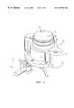
- FIG. 1is a perspective view of a lapping device in accordance with the present invention
- FIG. 2is a top plan view of the lapping device of FIG. 1;
- FIG. 3is a cross-section view of the invention taken along section line 3 — 3 in FIG. 2;
- FIG. 4is a top plan view of a lap tower or the lapping device of FIG. 1 with the lap removed;
- FIG. 5is a cross-section view of the invention taken along section line 5 — 5 in FIG. 3;
- FIG. 6is a schematic illustration of a single castellation on shafts of the lapping device as shown in FIG. 3;
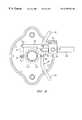
- FIG. 7is a bottom perspective view of the lapping device of FIG. 1 illustrating an actuation linkage arrangement preferred for the invention.
- FIG. 8is a bottom plan view of the lapping device of FIG. 1 .
- FIGS. 1 and 2an exterior perspective view and top plan view of the retaining mechanism for a lapping device 10 are illustrated.
- a lap 12externally exhibits no hold down features and is smooth.
- Lap 12comprises a domed top portion 14 and an annular skirt 16 depending therefrom which together define a hollowed interior.
- the domed portionis preferably of constant thickness.
- the lap of the inventionis securely, reliably, and in a failsafe manner, retained from the inside preferably, on a lap tower (support) 18 .
- Lap tower (support) 18is supported by a carrier (support) 20 that is securable to a machine housing (not shown).
- an actuator 22the balance of which is obscured under carrier 20 and which serves to actuate means for retaining lap 12 to the support, as described more fully hereinbelow.
- FIG. 3which is a cross section view of the invention taken along section line 3 — 3 in FIG. 2
- FIG. 4which is a schematic top view of lap tower 18
- FIG. 5which is a cross-section view of FIG. 3 taken along section line 5 — 5 in FIG. 3, the operational components of the invention are addressed.
- Each lap 12(the invention provides for a plurality of laps to be attached), individually, is secured to a lap tower 18 (preferably a plastic material) by a pair of blades 24 a and 24 b.
- blade 24 ais illustrated in the retracted position while blade 24 b is illustrated in the engaged position.
- the engaged positionis the failsafe position and the one where lap 12 is secured to tower 18 .
- Blades 24 a and 24 bwhen in the 24 a position, are received in a groove 26 which is cut in the hollowed interior of lap 12 , radially in skirt 16 .
- Lap 12then sits flush on top of tower 18 .
- Tower 18in turn is received in a recess 28 of carrier 20 which then is fastened to a machine housing (not shown) by fasteners which pass through bolt holes 30 in a flange 32 .
- Blades 24 a and 24 bare actuated by shafts 34 which extend though tower 18 and carrier 20 . Since tower 18 is in one embodiment (shown) plastic, bushings are not needed. In carrier 20 however it is preferable to apply a seal 36 in a seal bore 38 and a bushing (not shown) in a bushing bore 40 . Preferably the bushing material is bronze. The bushing and seal maintain an aligned position for shafts 34 in clearance bores 42 in carrier 20 . Shafts 34 extend below carrier 20 to be accessed by linkage to one of a number of actuators that are possible i.e. mechanical, hydraulic, electromechanical, electrical and pneumatic, with pneumatic being preferred.
- blades 24 a and 24 bare attached fixedly at one end 44 thereof to an upper end 46 of shafts 34 by preferably a threaded fastener 48 . Threaded fasteners are preferred to allow for disassembly if necessary.
- Threaded fastenersare preferred to allow for disassembly if necessary.
- At the upper end 46 of shafts 34are a single castellation 50 illustrated in FIG. 6 schematically.
- each blade 24includes a keyhole 52 comprising a fastener bore 54 and a dependent slot 56 . Slot 56 is provided to receive castellation 50 and prevents turning of blades 24 relative to their respective shafts 34 , once each blade 24 is fastened thereto with appropriate fasteners 48 .
- a cap ring 60(annular) is positioned over the blades and is secured to the tower 18 with preferably threaded fasteners (not shown) which extend through openings 62 . It should be noted that an upper surface 64 of cap ring 60 is beveled inwardly. This helps to return water, used to heat or cool lap 12 from the interior thereof, to a central drain port 66 .
- a pneumatic drive 68which is pivotally mounted through a bushing 70 to the housing (not shown) and a bushing 72 which rides in a frame section 74 that itself bolts to the housing.
- Frame section 74bolts through openings 76 .
- the pneumatic driveincludes a drive shaft 78 which at a distal end from the drive, includes a clevis 80 .
- Clevis 80is connected via a clevis pin 82 to an actuator arm 84 which is fixedly connected by threaded a fastener 86 to one shaft 34 .
- Actuator arm 84is further connected by a pivot pin 88 to a link 90 which connects via a pin 92 to a radius arm 94 which in turn is connected fixedly by a fastener 96 to the other shaft 34 .
- a single castellationis provided on each shaft. In FIG. 7, one of the castellations is visible and is identified as 98 .
- a springis preferably placed in operable contact with the driver assembly to maintain the assembly in the position where the lap is locked onto tower 18 .
- the springis not shown but could bear against any of the various linkage members or could be internal to the pneumatic drive so long as the bias tends to urge the drive in a direction opposite the actuation drive direction and into a position where blades 24 a and 24 b are engaged with groove 26 .
- the actuator 22is actuated overcoming the spring bias in the opposite direction and unlocks the blades 24 from the lap 12 .
- the lapWith the blades unlocked (disengaged from the lap groove 26 ) the lap easily is lifted off of tower 18 .
- Lapscould be automatically removed and replaced using a pick and place machine with a vacuum cup at the working end thereof which has been created by Gerber Coburn. The cup being selectively energized and deenergized.
- the deviceIn the event that power to the drive 68 is lost, the device is in the failsafe or locked mode.
- the devicecan still be actuated manually by a user gripping actuation arm grips 100 and 102 and moving them to overcome the spring bias of the system.
- pin 25which extends radially outwardly from tower 18 to positively locate lap 12 . While blades 24 , secure lap 12 from moving in the z-axis i.e. prevent removal of lap 12 from tower 18 , they do not prevent rotation about the z-axis. For cylindrical laps, rotation about the z-axis causes significant axis problems in a lens produced thereby and that lens would necessarily be defective. Pin 25 prevents rotation about the z-axis and so produces accurate axis for cylindrical correction. Lap 12 is simply and easily engaged with pin 25 by notch 27 . Notch 27 is preferably machined into lap 12 from a bottom edge 29 thereof (see FIG. 5 for location).
- the notch 27is flared at a bottom portion thereof to allow for some tolerance in aligning lap 12 .
- pin 25moves into the indexed position of notch 27 and the lap 12 is aligned properly and prevented from rotational movement about the z-axis.
- FIG. 7provides a view of a seal groove 104 that receives a seal such as an o-ring to pressure tightly seal the junction between the carrier 20 and the housing (not show). This is advantageous for other aspects of the system of which the invention forms a part.
Landscapes
- Engineering & Computer Science (AREA)
- Mechanical Engineering (AREA)
- Grinding And Polishing Of Tertiary Curved Surfaces And Surfaces With Complex Shapes (AREA)
- Finish Polishing, Edge Sharpening, And Grinding By Specific Grinding Devices (AREA)
Abstract
Description
Claims (10)
Priority Applications (7)
| Application Number | Priority Date | Filing Date | Title |
|---|---|---|---|
| US09/452,591US6375554B1 (en) | 1999-12-01 | 1999-12-01 | Retaining mechanism for lapping device |
| DE10057067ADE10057067A1 (en) | 1999-12-01 | 2000-11-17 | Pick-up mechanism for a lapping device |
| JP2000365323AJP4063492B2 (en) | 1999-12-01 | 2000-11-30 | Wrap retainer and method |
| GB0029205AGB2360724A (en) | 1999-12-01 | 2000-11-30 | A lap retaining mechanism |
| FR0015532AFR2802458B1 (en) | 1999-12-01 | 2000-11-30 | HOLDING MECHANISM FOR LAPPING DEVICE |
| US09/818,473US20010034193A1 (en) | 1999-12-01 | 2001-03-27 | Retaining mechanism for lapping device |
| JP2007302386AJP2008062381A (en) | 1999-12-01 | 2007-11-22 | Lap |
Applications Claiming Priority (1)
| Application Number | Priority Date | Filing Date | Title |
|---|---|---|---|
| US09/452,591US6375554B1 (en) | 1999-12-01 | 1999-12-01 | Retaining mechanism for lapping device |
Related Child Applications (1)
| Application Number | Title | Priority Date | Filing Date |
|---|---|---|---|
| US09/818,473DivisionUS20010034193A1 (en) | 1999-12-01 | 2001-03-27 | Retaining mechanism for lapping device |
Publications (1)
| Publication Number | Publication Date |
|---|---|
| US6375554B1true US6375554B1 (en) | 2002-04-23 |
Family
ID=23797080
Family Applications (2)
| Application Number | Title | Priority Date | Filing Date |
|---|---|---|---|
| US09/452,591Expired - Fee RelatedUS6375554B1 (en) | 1999-12-01 | 1999-12-01 | Retaining mechanism for lapping device |
| US09/818,473AbandonedUS20010034193A1 (en) | 1999-12-01 | 2001-03-27 | Retaining mechanism for lapping device |
Family Applications After (1)
| Application Number | Title | Priority Date | Filing Date |
|---|---|---|---|
| US09/818,473AbandonedUS20010034193A1 (en) | 1999-12-01 | 2001-03-27 | Retaining mechanism for lapping device |
Country Status (5)
| Country | Link |
|---|---|
| US (2) | US6375554B1 (en) |
| JP (2) | JP4063492B2 (en) |
| DE (1) | DE10057067A1 (en) |
| FR (1) | FR2802458B1 (en) |
| GB (1) | GB2360724A (en) |
Cited By (11)
| Publication number | Priority date | Publication date | Assignee | Title |
|---|---|---|---|---|
| US6561886B2 (en)* | 1999-12-01 | 2003-05-13 | Gerber Coburn Optical Inc. | Device for retaining abrasive pad on lap in eyeglass lens making apparatus |
| US20040235400A1 (en)* | 2000-08-07 | 2004-11-25 | Sangster Clive L. | Intermediate lens pad |
| US20050106999A1 (en)* | 2003-11-19 | 2005-05-19 | Matthew Vulich | Ophthalmic lens manufacturing system |
| US20080230006A1 (en)* | 2007-03-19 | 2008-09-25 | The Walman Optical Company | Lens coating system |
| US20080286458A1 (en)* | 2005-03-09 | 2008-11-20 | The Walman Optical Company | Method and Apparatus for Coating Optics |
| US20100136227A1 (en)* | 2008-09-10 | 2010-06-03 | The Walman Optical Company | Lens handling in automated lens coating systems |
| US20110102739A1 (en)* | 2008-02-14 | 2011-05-05 | Lefort Pascal | Methods and machines for lens deblocking |
| USD672799S1 (en) | 2011-03-16 | 2012-12-18 | Satisloh North America, Inc. | Optic device securing structure |
| USD673198S1 (en) | 2011-03-16 | 2012-12-25 | Satisloh North America, Inc. | Optic device securing structure |
| USD673598S1 (en)* | 2011-03-16 | 2013-01-01 | Satisloh North America, Inc. | Optic device securing structure |
| USD673597S1 (en)* | 2011-03-16 | 2013-01-01 | Satisloh North America, Inc. | Optic device securing structure |
Families Citing this family (3)
| Publication number | Priority date | Publication date | Assignee | Title |
|---|---|---|---|---|
| CN102172868B (en)* | 2011-02-16 | 2012-11-14 | 厦门大学 | Air floating big-calibre plane optical element polishing clamp |
| JP2013115304A (en)* | 2011-11-30 | 2013-06-10 | Nuflare Technology Inc | Charged particle beam lithography apparatus and charged particle beam lithography method |
| CN104457578A (en)* | 2014-12-30 | 2015-03-25 | 中国科学院长春光学精密机械与物理研究所 | Air flotation high-precision detection tool |
Citations (11)
| Publication number | Priority date | Publication date | Assignee | Title |
|---|---|---|---|---|
| US2747343A (en)* | 1954-09-02 | 1956-05-29 | Contur Abrasive Company Inc | Abrasive articles and the like and holders therefor |
| GB1568038A (en) | 1977-04-21 | 1980-05-21 | American Optical Corp | Lens surfacing tools |
| GB2196886A (en) | 1986-10-03 | 1988-05-11 | Wylde J & S Ltd | Lens tool |
| US5157880A (en)* | 1990-01-03 | 1992-10-27 | Coburn Optical Industries | Injection moldable plastic laps |
| US5209023A (en)* | 1990-05-18 | 1993-05-11 | Jerry Bizer | Thermoplastic polymer optical lap and method of making same |
| EP0804999A2 (en) | 1996-05-03 | 1997-11-05 | Coburn Optical Industries, Inc. | Pneumatically assisted unidirectional conformal tool |
| US5779529A (en)* | 1996-11-25 | 1998-07-14 | Bizer Industries | Thermoplastic optical lap with reinforced webbing |
| US5800255A (en)* | 1994-11-17 | 1998-09-01 | Coburn Optical Industries, Inc. | Lap adapter |
| US5931724A (en)* | 1997-07-11 | 1999-08-03 | Applied Materials, Inc. | Mechanical fastener to hold a polishing pad on a platen in a chemical mechanical polishing system |
| EP0974422A1 (en) | 1998-07-20 | 2000-01-26 | ESSILOR INTERNATIONAL (Compagnie Générale d'Optique) | Finishing tool, especially for ophtalmic lens, and equipment for using the same |
| US6244941B1 (en)* | 1999-03-30 | 2001-06-12 | Speedfam - Ipec Corporation | Method and apparatus for pad removal and replacement |
Family Cites Families (2)
| Publication number | Priority date | Publication date | Assignee | Title |
|---|---|---|---|---|
| US2932138A (en)* | 1958-11-10 | 1960-04-12 | Revere Camera Co | Method and apparatus for manufacturing precision lenses |
| US3135072A (en)* | 1961-12-08 | 1964-06-02 | Raphaels Ltd | Tool and tool holder assemblies for lens surfacing machines |
- 1999
- 1999-12-01USUS09/452,591patent/US6375554B1/ennot_activeExpired - Fee Related
- 2000
- 2000-11-17DEDE10057067Apatent/DE10057067A1/ennot_activeWithdrawn
- 2000-11-30GBGB0029205Apatent/GB2360724A/ennot_activeWithdrawn
- 2000-11-30JPJP2000365323Apatent/JP4063492B2/ennot_activeExpired - Fee Related
- 2000-11-30FRFR0015532Apatent/FR2802458B1/ennot_activeExpired - Fee Related
- 2001
- 2001-03-27USUS09/818,473patent/US20010034193A1/ennot_activeAbandoned
- 2007
- 2007-11-22JPJP2007302386Apatent/JP2008062381A/ennot_activeWithdrawn
Patent Citations (11)
| Publication number | Priority date | Publication date | Assignee | Title |
|---|---|---|---|---|
| US2747343A (en)* | 1954-09-02 | 1956-05-29 | Contur Abrasive Company Inc | Abrasive articles and the like and holders therefor |
| GB1568038A (en) | 1977-04-21 | 1980-05-21 | American Optical Corp | Lens surfacing tools |
| GB2196886A (en) | 1986-10-03 | 1988-05-11 | Wylde J & S Ltd | Lens tool |
| US5157880A (en)* | 1990-01-03 | 1992-10-27 | Coburn Optical Industries | Injection moldable plastic laps |
| US5209023A (en)* | 1990-05-18 | 1993-05-11 | Jerry Bizer | Thermoplastic polymer optical lap and method of making same |
| US5800255A (en)* | 1994-11-17 | 1998-09-01 | Coburn Optical Industries, Inc. | Lap adapter |
| EP0804999A2 (en) | 1996-05-03 | 1997-11-05 | Coburn Optical Industries, Inc. | Pneumatically assisted unidirectional conformal tool |
| US5779529A (en)* | 1996-11-25 | 1998-07-14 | Bizer Industries | Thermoplastic optical lap with reinforced webbing |
| US5931724A (en)* | 1997-07-11 | 1999-08-03 | Applied Materials, Inc. | Mechanical fastener to hold a polishing pad on a platen in a chemical mechanical polishing system |
| EP0974422A1 (en) | 1998-07-20 | 2000-01-26 | ESSILOR INTERNATIONAL (Compagnie Générale d'Optique) | Finishing tool, especially for ophtalmic lens, and equipment for using the same |
| US6244941B1 (en)* | 1999-03-30 | 2001-06-12 | Speedfam - Ipec Corporation | Method and apparatus for pad removal and replacement |
Cited By (13)
| Publication number | Priority date | Publication date | Assignee | Title |
|---|---|---|---|---|
| US6561886B2 (en)* | 1999-12-01 | 2003-05-13 | Gerber Coburn Optical Inc. | Device for retaining abrasive pad on lap in eyeglass lens making apparatus |
| US20040235400A1 (en)* | 2000-08-07 | 2004-11-25 | Sangster Clive L. | Intermediate lens pad |
| US6926597B2 (en)* | 2000-08-07 | 2005-08-09 | Cerium Group Limited | Intermediate lens pad |
| US20050106999A1 (en)* | 2003-11-19 | 2005-05-19 | Matthew Vulich | Ophthalmic lens manufacturing system |
| US7090559B2 (en) | 2003-11-19 | 2006-08-15 | Ait Industries Co. | Ophthalmic lens manufacturing system |
| US20080286458A1 (en)* | 2005-03-09 | 2008-11-20 | The Walman Optical Company | Method and Apparatus for Coating Optics |
| US20080230006A1 (en)* | 2007-03-19 | 2008-09-25 | The Walman Optical Company | Lens coating system |
| US20110102739A1 (en)* | 2008-02-14 | 2011-05-05 | Lefort Pascal | Methods and machines for lens deblocking |
| US20100136227A1 (en)* | 2008-09-10 | 2010-06-03 | The Walman Optical Company | Lens handling in automated lens coating systems |
| USD672799S1 (en) | 2011-03-16 | 2012-12-18 | Satisloh North America, Inc. | Optic device securing structure |
| USD673198S1 (en) | 2011-03-16 | 2012-12-25 | Satisloh North America, Inc. | Optic device securing structure |
| USD673598S1 (en)* | 2011-03-16 | 2013-01-01 | Satisloh North America, Inc. | Optic device securing structure |
| USD673597S1 (en)* | 2011-03-16 | 2013-01-01 | Satisloh North America, Inc. | Optic device securing structure |
Also Published As
| Publication number | Publication date |
|---|---|
| JP2008062381A (en) | 2008-03-21 |
| JP2001198783A (en) | 2001-07-24 |
| DE10057067A1 (en) | 2001-07-12 |
| FR2802458A1 (en) | 2001-06-22 |
| US20010034193A1 (en) | 2001-10-25 |
| GB0029205D0 (en) | 2001-01-17 |
| JP4063492B2 (en) | 2008-03-19 |
| GB2360724A (en) | 2001-10-03 |
| FR2802458B1 (en) | 2003-04-18 |
Similar Documents
| Publication | Publication Date | Title |
|---|---|---|
| US6375554B1 (en) | Retaining mechanism for lapping device | |
| CN101626868B (en) | Machine for shaping ophthalmic lenses, provided with a tool carrier on which a plurality of working tools are mounted | |
| US8342909B2 (en) | Device for machining ophthalmic lenses, the device having a plurality of machining tools placed on a swivel module | |
| US5951375A (en) | Support for optical lenses and method for polishing lenses | |
| US6336849B1 (en) | Grinding spindle | |
| JP5698756B2 (en) | Method for grinding crankshaft main and rod bearings by cylindrical grinding and grinding machine for carrying out the method | |
| US6428397B1 (en) | Wafer edge polishing method and apparatus | |
| US7281967B2 (en) | Machine for grinding optical lenses | |
| US6739954B2 (en) | Grinding pin for grinding machines comprising resin bonded selections of rough grit and fine grit | |
| EP2101936B1 (en) | Chuck and process for manufacturing a vehicle wheel rim employing said chuck | |
| JPH0698563B2 (en) | Glass plate grinding machine | |
| US6464559B2 (en) | Device for retaining abrasive pad on lap in eyeglass lens making apparatus | |
| KR20070096720A (en) | Lens grinding device with chamfering mechanism | |
| CN101043976A (en) | Device and method for adjusting the drilling direction of a drilling tool for an ophthalmic lens | |
| US7223164B2 (en) | Optical surface-finishing tool | |
| CN109746812B (en) | Surface treatment station for manufacturing optical elements and related manufacturing facility | |
| JPS597550A (en) | Curved-surface grinding machining machine | |
| US6220938B1 (en) | Grinding machines | |
| CN109531304A (en) | Achievable Large Crankshaft turns the clamping tooling of neck rubbing down and the method with its rubbing down | |
| JP4457073B2 (en) | Vertical double-sided surface grinding machine | |
| US2364804A (en) | Grinder | |
| CZ304718B6 (en) | Fully automatic method for blocking optical lenses | |
| CN216228394U (en) | Lathe main shaft taper hole prosthetic devices | |
| JPH0398753A (en) | Curvature working device for slipper face of rocker arm | |
| CN119897721A (en) | Multi-angle processing tooling for automobile steering knuckle |
Legal Events
| Date | Code | Title | Description |
|---|---|---|---|
| AS | Assignment | Owner name:GERBER COBURN OPTICAL INC., CONNECTICUT Free format text:ASSIGNMENT OF ASSIGNORS INTEREST;ASSIGNORS:MURRAY, JEFFREY;DOOLEY, JONATHAN;WOLFSON, LAWRENCE;REEL/FRAME:010419/0295 Effective date:19991122 | |
| FEPP | Fee payment procedure | Free format text:PAYOR NUMBER ASSIGNED (ORIGINAL EVENT CODE: ASPN); ENTITY STATUS OF PATENT OWNER: LARGE ENTITY | |
| FPAY | Fee payment | Year of fee payment:4 | |
| AS | Assignment | Owner name:CITIZENS BANK OF MASSACHUSETTS, MASSACHUSETTS Free format text:INTELLECTUAL PROPERTY SECURITY AGREEMENT;ASSIGNOR:GERBER SCIENTIFIC, INC.;REEL/FRAME:016987/0139 Effective date:20051031 | |
| REMI | Maintenance fee reminder mailed | ||
| FPAY | Fee payment | Year of fee payment:8 | |
| SULP | Surcharge for late payment | Year of fee payment:7 | |
| AS | Assignment | Owner name:GERBER SCIENTIFIC INTERNATIONAL, INC., CONNECTICUT Free format text:TERMINATION AND RELEASE OF SECURITY INTEREST IN INTELLECTUAL PROPERTY;ASSIGNOR:RBS CITIZENS, N.A.;REEL/FRAME:025642/0153 Effective date:20101231 Owner name:GERBER SCIENTIFIC INC., CONNECTICUT Free format text:TERMINATION AND RELEASE OF SECURITY INTEREST IN INTELLECTUAL PROPERTY;ASSIGNOR:RBS CITIZENS, N.A.;REEL/FRAME:025642/0153 Effective date:20101231 Owner name:COBURN TECHNOLOGIES, INC., CONNECTICUT Free format text:ASSIGNMENT OF ASSIGNORS INTEREST;ASSIGNOR:GERBER SCIENTIFIC INTERNATIONAL, INC;REEL/FRAME:025763/0344 Effective date:20101231 Owner name:GERBER COBURN OPTICAL INTERNATIONAL, INC., CONNECT Free format text:TERMINATION AND RELEASE OF SECURITY INTEREST IN INTELLECTUAL PROPERTY;ASSIGNOR:RBS CITIZENS, N.A.;REEL/FRAME:025642/0153 Effective date:20101231 | |
| AS | Assignment | Owner name:PNC BANK, NATIONAL ASSOCIATION, PENNSYLVANIA Free format text:SECURITY AGREEMENT;ASSIGNORS:COBURN TECHNOLOGIES, INC.;COBURN TECHNOLOGIES INTERNATIONAL, INC.;REEL/FRAME:026079/0254 Effective date:20101231 | |
| REMI | Maintenance fee reminder mailed | ||
| LAPS | Lapse for failure to pay maintenance fees | ||
| STCH | Information on status: patent discontinuation | Free format text:PATENT EXPIRED DUE TO NONPAYMENT OF MAINTENANCE FEES UNDER 37 CFR 1.362 | |
| FP | Lapsed due to failure to pay maintenance fee | Effective date:20140423 |