US6374729B1 - Apparatus for transporting circuit boards in a screen printer - Google Patents
Apparatus for transporting circuit boards in a screen printerDownload PDFInfo
- Publication number
- US6374729B1 US6374729B1US09/460,053US46005399AUS6374729B1US 6374729 B1US6374729 B1US 6374729B1US 46005399 AUS46005399 AUS 46005399AUS 6374729 B1US6374729 B1US 6374729B1
- Authority
- US
- United States
- Prior art keywords
- operation position
- substrate
- conveyor
- conveyor system
- post
- Prior art date
- Legal status (The legal status is an assumption and is not a legal conclusion. Google has not performed a legal analysis and makes no representation as to the accuracy of the status listed.)
- Expired - Lifetime
Links
- 239000000758substrateSubstances0.000claimsabstractdescription101
- 239000000463materialSubstances0.000claimsabstractdescription8
- 229910000679solderInorganic materials0.000claimsdescription12
- 230000032258transportEffects0.000claimsdescription12
- 230000004044responseEffects0.000claimsdescription3
- 238000000034methodMethods0.000abstractdescription7
- 230000009977dual effectEffects0.000description5
- 238000004519manufacturing processMethods0.000description5
- 230000004075alterationEffects0.000description2
- 230000006872improvementEffects0.000description2
- 238000012986modificationMethods0.000description2
- 230000004048modificationEffects0.000description2
- 230000009286beneficial effectEffects0.000description1
- 238000010586diagramMethods0.000description1
- 230000007246mechanismEffects0.000description1
- 230000003287optical effectEffects0.000description1
- 238000011144upstream manufacturingMethods0.000description1
- 235000012431wafersNutrition0.000description1
Images


Classifications
- H—ELECTRICITY
- H05—ELECTRIC TECHNIQUES NOT OTHERWISE PROVIDED FOR
- H05K—PRINTED CIRCUITS; CASINGS OR CONSTRUCTIONAL DETAILS OF ELECTRIC APPARATUS; MANUFACTURE OF ASSEMBLAGES OF ELECTRICAL COMPONENTS
- H05K3/00—Apparatus or processes for manufacturing printed circuits
- H05K3/10—Apparatus or processes for manufacturing printed circuits in which conductive material is applied to the insulating support in such a manner as to form the desired conductive pattern
- H05K3/12—Apparatus or processes for manufacturing printed circuits in which conductive material is applied to the insulating support in such a manner as to form the desired conductive pattern using thick film techniques, e.g. printing techniques to apply the conductive material or similar techniques for applying conductive paste or ink patterns
- H05K3/1216—Apparatus or processes for manufacturing printed circuits in which conductive material is applied to the insulating support in such a manner as to form the desired conductive pattern using thick film techniques, e.g. printing techniques to apply the conductive material or similar techniques for applying conductive paste or ink patterns by screen printing or stencil printing
- B—PERFORMING OPERATIONS; TRANSPORTING
- B41—PRINTING; LINING MACHINES; TYPEWRITERS; STAMPS
- B41F—PRINTING MACHINES OR PRESSES
- B41F15/00—Screen printers
- B41F15/08—Machines
- B41F15/0881—Machines for printing on polyhedral articles
Definitions
- the present inventionrelates generally to the field of electronics manufacturing, and more specifically to an improved apparatus and method for transporting substrates, such as circuit boards, in a screen or stencil printer that prints solder paste on a surface of the substrates.
- FIG. 1A typical example of a circuit board assembly line 10 is shown in block format in FIG. 1 .
- the assembly lineincludes a circuit board loader 12 , a stencil printer 14 , a pick and place machine 16 and a reflow oven 18 .
- the machines in the assembly lineare interconnected using a number of conveyor segments 20 .
- the circuit board loader 12provides a bare circuit board to the stencil printer wherein solder paste is printed onto pads of the circuit board in a predetermined pattern defined by a stencil loaded into the stencil printer.
- the stencil printerthen passes the circuit board to the pick and place machine 16 , wherein electrical components are placed onto the solder paste on the circuit board.
- the circuit boardis passed to the reflow oven, wherein the circuit board is subjected to a sufficiently high temperature to cause the solder paste to flow to secure the components to the board and provide proper electrical connections between the components and the circuit board.
- FIG. 2One example of a stencil printer 14 is shown in FIG. 2 .
- Stencil printerslike that shown in FIG. 2, are available from MPM Corporation, Franklin Mass. the assignee of the present invention, and include model numbers ULTRAPRINT 2000, ULTRAPRINT 2500 and ULTRAPRINT 3000.
- the stencil printer 14includes a frame 22 that supports components of the stencil printer including a controller 24 with a user interface 26 , a stencil 28 , and a dispensing head 30 having a dispensing slot 32 from which solder paste is dispensed.
- a z-axis work tablelifts the circuit board to place the circuit board against, or in close proximity with, the stencil of the printer so that printing can occur.
- the dispensing head 30is then placed over the stencil and moved across the stencil while solder paste is dispensed through the slot 32 , causing the solder paste to be printed onto the circuit board.
- the operation of the dispensing head 30is further described in co-pending U.S. patent application Ser. No. 08/966,057 (now U.S. Pat. No. 5,947,022) to Freeman et. al, which is assigned to the assignee of the present invention, and incorporated by reference herein.
- some prior art stencil printersutilize one or more squeegee blades with a paste dispensing mechanism in place of the dispensing head described above.
- the stencil printer 14includes a conveyor 34 for loading/unloading and for positioning circuit boards in a print area above the z-axis work table of the screen printer.
- the conveyor 34 of the stencil printeris positioned to receive circuit boards 36 from and deliver circuit boards 36 to conveyor sections 20 of an assembly line, as shown in FIG. 1, to move circuit boards 36 between the machines in the assembly line.
- Typical inline circuit board manufacturing machinessuch as those shown in FIG. 1, communicate with each other using standard protocols defined by the Surface Mount Equipment Manufacturer's Association (SMEMA) to transfer substrates such as circuit boards between the machines.
- SMEMASurface Mount Equipment Manufacturer's Association
- the stencil printer 14signals to the pick and place machine that it has a circuit board 36 ready to transfer to the pick and place machine, and when the pick and place machine signals to the stencil printer that it is ready to receive the circuit board 36 , then the circuit board 36 is transferred over conveyor section 20 .
- conveyor 34 in the stencil printeris comprised of three independently controllable conveyor segments 34 a , 34 b and 34 c .
- the three segmentsdefine three circuit board positions identified as a pre-print position 38 , a print position 40 and a post-print position 42 .
- Circuit boardsare initially loaded into the pre-print position 38 , move to the print position 40 within the print area 44 of the screen printer, and after printing, move to the post-print position 42 to wait to be unloaded from the stencil printer.
- Embodiments of the present inventionprovide a method and apparatus for transporting circuit boards in a screen printer having the advantages of a three conveyor segment conveyor system, without the above-described disadvantages.
- a transportation systemfor a printer that prints material on a substrate.
- the transportation systemloads substrates into the printer, unloads substrates from the printer and transports substrates between positions within the printer.
- the transportation systemincludes a conveyor disposed within the printer that receives a substrate to be printed on, and that moves the substrate to predetermined substrate positions in the printer, wherein at least one of the predetermined substrate positions is a print position at which the material is printed onto the substrate, and means for independently controlling movement of a plurality of substrates on the conveyor.
- the means for independently controlling movementincludes at least one device that lifts at least one substrate off of the conveyor such that the substrate does not move in response to movement of the conveyor.
- the means for independently controllingincludes a least one pin having an activated position in which at least one substrate is prevented from moving beyond the pin on the conveyor.
- Another embodiment of the present inventionis directed to a method of printing material on substrates using a printer having a transportation system that transports the substrates to positions within the printer.
- the methodincludes steps of transferring a first substrate to a print position in the printer using the transportation system, raising the first substrate off of the transportation system to print the material on the substrate, transferring a second substrate to a pre-print position in the printer while the first substrate is raised off of the transportation system and raising the second substrate off of the transportation system, transferring the first substrate to a post-print position and raising the first substrate off of the transportation system, lowering the second substrate onto the transportation system, transferring the second substrate to the print position and raising the second substrate off of the transportation system to print material on the second substrate, and while the first and second substrates are raised above the transportation system, transferring a third substrate to the pre-print position and raising the third substrate off of the transportation system.
- the methodmay further include steps of lowering the first substrate back onto the transportation system, and transferring the first substrate from the post-print position.
- FIG. 1is a block diagram of a typical inline operation for manufacturing electronic circuit boards
- FIG. 2is a front-view of a typical screen printer used in the inline operation shown in FIG. 1;
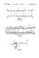
- FIG. 3is an illustration of a typical three segment conveyor used in prior art screen printers
- FIG. 4is an illustration of a top view of a conveyor system in accordance with a first embodiment of the present invention
- FIG. 5is an illustration of a cross-sectional side view of the conveyor system of FIG. 4 with a circuit board in a lowered position;
- FIG. 6is an illustration of a cross-sectional side view of the conveyor system of FIG. 4 with a circuit board in a raised position;
- FIG. 7is an illustration showing the top view of the conveyor system of FIG. 4 with a first circuit board located at a print position on the conveyor system;
- FIG. 8is an illustration showing the top view of the conveyor system of FIG. 4 with a first circuit board located at a print position on the conveyor system and a second circuit board located at a pre-print queue position on the conveyor system;
- FIG. 9is an illustration showing the top view of the conveyor system of FIG. 4 with a first circuit board located at a post-print queue position, a second circuit board located at a print position and a third circuit board located at a pre-print queue position;
- FIG. 10is an illustration showing a top view of a conveyor system in accordance with one embodiment of the present invention having adjustable circuit board lifters to accommodate different size circuit boards;
- FIG. 11is an illustration showing a top view of a conveyor system in accordance with a second embodiment of the present invention.
- FIG. 12is an illustration of a cross-sectional side view of the conveyor system of FIG. 11 showing a circuit board stop in a retracted position
- FIG. 13is an illustration showing the cross-sectional side view of the conveyor system of FIG. 11 with the circuit board stop in an engaged position.
- embodiments of the present inventionare described herein with reference to a stencil printer for printing solder paste on a substrate such as a circuit board.
- a stencil printerfor printing solder paste on a substrate
- a substratesuch as a circuit board.
- embodiments of the present inventionare not limited to stencil printers, but rather, may be used in other equipment that utilizes conveyors or similar transportation systems for loading and unloading workpieces or substrates.
- screen and stencilmay be used interchangeably herein to describe a device in a printer that defines a pattern to be printed on a substrate.
- a single segment conveyor system for a stencil printerhaving multiple substrate positions defined thereon, and having the capability for independently loading substrates into the printer, unloading substrates from the printer, and moving substrates from one position to another position on the conveyor system without moving all other substrates.
- FIG. 4A top view of a first embodiment of the present invention of a conveyor system 100 for a stencil printer, such as stencil printer 14 of FIG. 2, is shown in FIG. 4 .
- the conveyor system 100has a pair of transport rails 102 a and 102 b having conveyor belts 103 a and 103 b for transporting circuit boards within a stencil printer, and has a print area 104 , that is positioned over the z-axis work table in the printer.
- the z-axis work tablehas worknest tooling 106 for raising circuit boards off of the conveyor belts to place the circuit boards in proximity with the stencil of the printer when printing is to occur.
- the conveyor system 100also has a pair of pre-print queue circuit board lifters 108 a and 108 b , a pair of post-print queue circuit board lifters 110 a and 110 b , and four circuit board sensors 114 , 116 , 118 and 120 .
- the conveyor system 100 shown in FIG. 4transfers circuit boards in the direction shown by arrows 112 , so that circuit boards enter the conveyor system near circuit board sensor 114 , and printed circuit boards exit the conveyor system near circuit board sensor 120 .
- Each pair of circuit board lifters 108 a and 108 b , and 110 a and 10 bis disposed within the conveyor system 100 , so that under the control of the controller of a stencil printer, each pair of lifters can raise a circuit board off of the conveyor belts 103 a and 103 b to prevent the circuit board from moving with the conveyor belts.
- Circuit board sensors 114 , 116 , 118 and 120are used to detect positions of circuit boards in the conveyor system and to report the positions to the controller of the stencil printer. In one embodiment of the present invention, the sensors may be implemented using one of a number of optical techniques as known in the art.
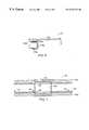
- FIG. 5is a cross-sectional view of the conveyor system 100 , taken along line 5 — 5 of FIG. 4, with a circuit board 122 loaded in a transport or lowered position in the conveyor system 100 . Only one of the transfer rails 102 a is shown in the cross-sectional view of FIG. 5 . The other transfer rail 102 b is substantially identical to transfer rail 102 a .
- the circuit board 122is disposed on the conveyor belt 103 a adjacent a rail cap 124 which is used to maintain the conveyor belt in its proper position on the transfer rail 102 a .
- the circuit board lifter 108 ais below the circuit board 122 allowing the circuit board to rest on the conveyor belt and move with the conveyor belt.
- FIG. 6shows a cross-sectional view, similar to FIG. 5, except that in FIG. 6, the circuit board is in a lifted position off of the conveyor belt, preventing the circuit board from moving with the conveyor belt.
- pneumatic cylinders and mechanical linkagesunder the control of the controller of the printer, are activated causing lifters 108 a and 108 b to rise, lifting the circuit board 122 off of the conveyor belts.
- a first circuit board 122 ais loaded in the conveyor system and transported to the print area above the z-axis tower, as shown in FIG. 7 .
- Circuit board 122 ais then lifted off of the conveyor belt by the worknest tooling to place the circuit board against the stencil for printing.
- a second circuit board 122 bis then loaded into the stencil printer using the conveyor.
- sensor 116detects the front edge of the circuit board, the conveyor is stopped, and circuit board lifters 108 a and 108 b are activated to lift circuit board 108 b off of the conveyor belts.
- Circuit board 122 bis then positioned at a pre-print queue position, defined by the pre-print queue circuit board lifters 108 a and 108 b , as shown in FIG. 8 . While the second circuit board 122 b is transported to the pre-print queue position, the first circuit board 122 a remains in the position shown in FIG. 7, since it is disposed above the conveyor belts.
- the first circuit board 122 aWhen printing on the first circuit board 122 a is completed, the first circuit board 122 a is lowered back onto the conveyor belts, and the conveyor belts are actuated by the controller to move the first circuit board 122 a to a post-print queue position, defined by the post-print circuit board lifters 110 a and 110 b .
- the conveyor stops, and circuit board lifters 110 a and 110 blift circuit board 122 a off of the conveyor belts.
- the second circuit board 122 bis then lowered onto the conveyor, moved into the print position and then lifted off of the conveyor belts for printing.
- FIG. 9shows a top view of the conveyor system 100 with the first circuit board 122 a at the post-print queue position, the second circuit board 122 b at the print position and the third circuit board 122 c at the pre-print queue position.
- the first circuit board 122 ais lowered onto the conveyor belts, and the conveyor belts are activated to transport circuit board 122 a from the stencil printer.
- the first circuit boardmay be transported from the screen printer while printing is occurring on the second circuit board.
- the second circuit boardis moved to the post-print position, the third circuit board is moved to the print position, and a fourth circuit board may be loaded into the stencil printer.
- the controller of the screen printeris programmed to control the circuit board lifters, to control the conveyor, and to respond to the sensors to provide the operation described above.
- the controlleris programmed to control the circuit board lifters and conveyor belts in response to commands (for example, commands using the SMEMA defined protocols) received from upstream and downstream machines in an assembly line.
- each of the circuit boards shown in the figuresare of approximately the maximum size that the stencil printer is designed to accommodate, since the boards occupy most of the print area of the stencil printer. It is often desirable to print on circuit boards that occupy a significantly less portion of the print area than the boards described above, and in some prior art screen printers, the width W (see, FIG. 4) between the transport rails of the conveyor system is adjustable. In embodiments of the present invention, to accommodate smaller circuit boards, the width W between the transport rails is adjustable, and in addition, the length of the circuit board lifters and the effective length of the worknest tooling in the print area are adjustable using various length parts that can be quickly interchanged. The ability to adjust the circuit board lifters allows circuit boards in the pre-print and post-print queue positions to extend into the print area to reduce the time required to transport circuit boards between positions in the conveyor system.
- FIG. 10shows the conveyor system 100 adjusted to accommodate circuit boards 124 a , 124 b and 124 c that are significantly smaller than the print area 104 of the screen printer.
- the effective length of the worknest tooling, used to lift the circuit boards in the print areahas been reduced, and the length of each of the circuit board lifters 108 a , 108 b , 110 a and 110 b has been increased so that each of the circuit board lifters extends into the print area.
- the positions of sensors 116 and 118have also been adjusted to accommodate the smaller circuit boards.
- circuit boards used with embodiments of the present invention described abovehave sufficient edge clearance between the edge of the circuit boards and any components mounted on the underside of the circuit boards, so that the circuit board lifters do not contact any underside components.
- the desired edge clearance for circuit boards to be used with the circuit board liftersis approximately 5 mm.
- the circuit board liftersare replaced with retractable board stops.
- the board stopshave a retracted position in which they are disposed below the conveyor system and can be raised to an engaged position to contact a front edge of a circuit board. In the engaged position, the board stops contact the front edge of a circuit board to prevent the circuit board from moving with the conveyor belts.
- at least one board stopis provided at the pre-print queue position and at the post-print queue position. The board stops are controlled by the controller of a stencil printer in a manner similar to the circuit board lifters discussed above, however, in this embodiment, rather than lifting the circuit boards off of the conveyor, the circuit boards are held in position by the board stops while the conveyor slides under them.
- FIG. 11shows a conveyor system 200 that is similar to the conveyor system 100 discussed above and similar components are identified with the same reference numbers.
- Conveyor system 200differs from conveyor system 100 in that the circuit board lifters in the conveyor system 100 have been replaced by four retractable circuit board stops 208 a , 208 b , 210 a , 210 b .
- a first pair of the circuit board stops 208 a and 208 bare used to maintain a circuit board (such as circuit board 122 c of FIG. 11) in the pre-print queue position, and a second pair of circuit board stops are used to maintain a circuit board (such as circuit board 122 a of FIG. 11) in the post-print queue position.
- FIGS. 12 and 13show a cross-sectional view of the conveyor system 200 taken along line 12 — 12 of FIG. 11 .
- circuit board stop 208 ais shown in a retracted position
- circuit board stop 208 ais shown in an engaged position.
- the circuit board 122 cis allowed to move with the conveyor belt 103 a
- the circuit board 122 cis prevented from moving with the conveyor belt.
- circuit board stop 208 aas well as circuit board stops 208 b , 210 a and 210 b , are implemented using a pneumatic cylinder 111 having a pin 109 that may be engaged by providing pressurized air to the pneumatic cylinder, as is known to those skilled in the art.
- the circuit board stopsare implemented using standard pneumatic cylinders as known in the art.
- the circuit board stopsmay be implemented using one of a number of devices, using an electrical actuator, a pneumatic actuator or some other type of actuator for engaging and retracting a pin, a piston or some similar device.
- circuit board stopsto control movement of circuit boards has several advantages. First, they are relatively simple to implement, and can be easily made adjustable to accommodate different board sizes. Second, for printing on smaller circuit boards, the board stops can easily be moved into the print area of the screen printer, since little hardware is needed to implement the board stops.
- a circuit board stopis also used in conjunction with the worknest tooling to stop circuit boards at the proper print position below the stencil.
- the conveyor beltscan be reversed to properly place circuit boards below the stencil.
- any boards at the pre-print or post-print positionswill be undesirably moved backwards in the conveyor system.
- additional circuit board stopsare provided, as shown in FIG. 11, that contact the back edge of circuit boards and hold the circuit boards at the proper position in the conveyor system when the conveyor belts are reversed.
- a conveyor systemmay consist of at least one segment having multiple independently controllable circuit board positions and at least one other segment having one, or more than one, circuit board position.
- a pre-print positionmay have a dedicated conveyor segment and the print and post-print positions may share a conveyor segment with the print and post-print positions being independently controllable.
- conveyor systems having three circuit board positionshave been described.
- the present inventionis not limited to a conveyor system with three circuit board positions, but rather, includes conveyor systems having either more or less than three positions.
- Embodiments of the present inventionhave been described above as being used with stencil printers that print solder paste on circuit boards. As understood by those skilled in the art, embodiments of the present invention are not limited to systems that print on circuit boards, but also include systems that print on other substrates, such as wafers or cards.
- Embodiments of the present inventionhave been described as being implemented in a stencil printer.
- two conveyor systems in accordance with one of the above-described embodimentsare incorporated in a stencil printer having a dual track mode, such as the ULTRAPRINT 2500 stencil printer available from MPM Corporation, Franklin, Mass. and as described in U.S. patent application Ser. No. 08/802,934 (now U.S. Pat. No. 5,873,939), entitled “Dual Track Stencil/Screen Printer and U.S. patent application Ser. No. 08/920,121 (now U.S. Pat. No.
Landscapes
- Engineering & Computer Science (AREA)
- Manufacturing & Machinery (AREA)
- Microelectronics & Electronic Packaging (AREA)
- Mechanical Engineering (AREA)
- Screen Printers (AREA)
- Electric Connection Of Electric Components To Printed Circuits (AREA)
- Manufacturing Of Printed Wiring (AREA)
Abstract
Description
Claims (31)
Priority Applications (1)
| Application Number | Priority Date | Filing Date | Title |
|---|---|---|---|
| US09/460,053US6374729B1 (en) | 1998-03-02 | 1999-12-13 | Apparatus for transporting circuit boards in a screen printer |
Applications Claiming Priority (2)
| Application Number | Priority Date | Filing Date | Title |
|---|---|---|---|
| US09/033,231US6032577A (en) | 1998-03-02 | 1998-03-02 | Method and apparatus for transporting substrates |
| US09/460,053US6374729B1 (en) | 1998-03-02 | 1999-12-13 | Apparatus for transporting circuit boards in a screen printer |
Related Parent Applications (1)
| Application Number | Title | Priority Date | Filing Date |
|---|---|---|---|
| US09/033,231DivisionUS6032577A (en) | 1998-03-02 | 1998-03-02 | Method and apparatus for transporting substrates |
Publications (1)
| Publication Number | Publication Date |
|---|---|
| US6374729B1true US6374729B1 (en) | 2002-04-23 |
Family
ID=21869250
Family Applications (2)
| Application Number | Title | Priority Date | Filing Date |
|---|---|---|---|
| US09/033,231Expired - LifetimeUS6032577A (en) | 1998-03-02 | 1998-03-02 | Method and apparatus for transporting substrates |
| US09/460,053Expired - LifetimeUS6374729B1 (en) | 1998-03-02 | 1999-12-13 | Apparatus for transporting circuit boards in a screen printer |
Family Applications Before (1)
| Application Number | Title | Priority Date | Filing Date |
|---|---|---|---|
| US09/033,231Expired - LifetimeUS6032577A (en) | 1998-03-02 | 1998-03-02 | Method and apparatus for transporting substrates |
Country Status (5)
| Country | Link |
|---|---|
| US (2) | US6032577A (en) |
| EP (1) | EP1060080A1 (en) |
| JP (1) | JP2002505530A (en) |
| CA (1) | CA2320748A1 (en) |
| WO (1) | WO1999044828A1 (en) |
Cited By (22)
| Publication number | Priority date | Publication date | Assignee | Title |
|---|---|---|---|---|
| US20010049875A1 (en)* | 2000-02-25 | 2001-12-13 | Shinji Watanabe | Size reduction of chip mounting system |
| US6526652B2 (en)* | 2000-08-04 | 2003-03-04 | Fuji Machine Mfg. Co., Ltd. | Apparatus for resetting printed-wiring-board supporting device, and printed-wiring-board-relating-operation performing system |
| US6564446B2 (en)* | 2000-11-02 | 2003-05-20 | Koninklijke Philips Electronics N.V. | Component placement machine |
| US20030127305A1 (en)* | 2000-11-01 | 2003-07-10 | Gordon Brian F. | Printed circuit board support |
| US6614220B2 (en)* | 2000-10-19 | 2003-09-02 | Mania Tecnologie Italia Spa | Method and device for automatic adjustment of printed circuit board conveying means in a test machine |
| US6619462B2 (en)* | 2000-03-22 | 2003-09-16 | Siemens Production And Logistics Systems Ag | Device for conveying printed boards |
| US20040142099A1 (en)* | 2003-01-17 | 2004-07-22 | Mark Rossmeisl | Electronic substrate printing |
| US20050167238A1 (en)* | 2003-11-28 | 2005-08-04 | Sony Corporation | Work transfer apparatus |
| US20060040521A1 (en)* | 2004-08-17 | 2006-02-23 | Gordon Brian F | Printed circuit board support |
| US20090056569A1 (en)* | 2007-08-30 | 2009-03-05 | Mimaki Engineering Co., Ltd. | Printing apparatus |
| US20090320699A1 (en)* | 2008-06-24 | 2009-12-31 | Machines Dubuit | Printing machine |
| US20100122633A1 (en)* | 2008-11-19 | 2010-05-20 | Illinois Tool Works Inc. | Vertically separated pass through conveyor system and method in surface mount technology process equipment |
| US20140027252A1 (en)* | 2012-07-30 | 2014-01-30 | Hon Hai Precision Industry Co., Ltd. | Transferring device |
| CN103771113A (en)* | 2012-10-24 | 2014-05-07 | 鸿富锦精密工业(深圳)有限公司 | Material conveying device |
| US9370925B1 (en) | 2015-03-25 | 2016-06-21 | Illinois Tool Works Inc. | Stencil printer having stencil shuttle assembly |
| US9370923B1 (en) | 2015-04-07 | 2016-06-21 | Illinois Tool Works Inc. | Lift tool assembly for stencil printer |
| US9370924B1 (en) | 2015-03-25 | 2016-06-21 | Illinois Tool Works Inc. | Dual action stencil wiper assembly for stencil printer |
| US20170034967A1 (en)* | 2014-01-30 | 2017-02-02 | Fuji Machine Mfg. Co., Ltd. | Board conveyance device and board work system including the board conveyance device |
| DE102018205944A1 (en)* | 2018-04-18 | 2019-10-24 | Ekra Automatisierungssysteme Gmbh | Printing system for printing on substrates, method for operating the printing system |
| US10703089B2 (en) | 2015-04-07 | 2020-07-07 | Illinois Tool Works Inc. | Edge lock assembly for a stencil printer |
| US10723117B2 (en) | 2015-04-07 | 2020-07-28 | Illinois Tool Works Inc. | Lift tool assembly for stencil printer |
| US11577502B2 (en) | 2018-04-05 | 2023-02-14 | Ekra Automatisierungssysteme Gmbh | Printing device |
Families Citing this family (22)
| Publication number | Priority date | Publication date | Assignee | Title |
|---|---|---|---|---|
| US6066206A (en)* | 1997-02-21 | 2000-05-23 | Speedline Technologies, Inc. | Dual track stenciling system with solder gathering head |
| JP4046391B2 (en)* | 1997-11-28 | 2008-02-13 | 松下電器産業株式会社 | Printed circuit board transport apparatus and transport method |
| DE19936553C2 (en)* | 1999-08-03 | 2002-06-27 | Thieme Gmbh & Co Kg | Printing table for a screen printing machine |
| US20030021886A1 (en)* | 2000-02-23 | 2003-01-30 | Baele Stephen James | Method of printing and printing machine |
| US7008128B1 (en)* | 2000-07-27 | 2006-03-07 | Tadayoshi Nakanishi | System, method and apparatus for printing oversized print media |
| US20020062553A1 (en)* | 2000-11-24 | 2002-05-30 | Mirae Corporation | Surface mounting device and method thereof |
| KR100412273B1 (en)* | 2001-11-22 | 2003-12-31 | 미래산업 주식회사 | Apparatus for Transferring Printed Circuit Board |
| US20050108872A1 (en)* | 2001-12-18 | 2005-05-26 | Willibald Konrath | Apparatus and method for assembling electronic circuits |
| US7118103B2 (en)* | 2003-04-14 | 2006-10-10 | Heidelberger Druckmaschinen Ag | Device for conveying sheets through a printing machine |
| US20120292367A1 (en) | 2006-01-31 | 2012-11-22 | Ethicon Endo-Surgery, Inc. | Robotically-controlled end effector |
| US7861650B2 (en)* | 2007-04-13 | 2011-01-04 | Illinois Tool Works, Inc. | Method and apparatus for adjusting a substrate support |
| JP2009009972A (en)* | 2007-06-26 | 2009-01-15 | Yokota Technica:Kk | Reflow soldering equipment |
| GB2452320B (en)* | 2007-09-03 | 2012-04-11 | Dek Int Gmbh | Workpiece processing system and method |
| US7866527B2 (en) | 2008-02-14 | 2011-01-11 | Ethicon Endo-Surgery, Inc. | Surgical stapling apparatus with interlockable firing system |
| EP2106916B1 (en)* | 2008-03-31 | 2011-05-04 | Dainippon Screen Mfg., Co., Ltd. | Image recording apparatus |
| US8215473B2 (en)* | 2008-05-21 | 2012-07-10 | Applied Materials, Inc. | Next generation screen printing system |
| US9386983B2 (en) | 2008-09-23 | 2016-07-12 | Ethicon Endo-Surgery, Llc | Robotically-controlled motorized surgical instrument |
| US9351730B2 (en) | 2011-04-29 | 2016-05-31 | Ethicon Endo-Surgery, Llc | Tissue thickness compensator comprising channels |
| DE102014116879B3 (en)* | 2014-11-18 | 2015-11-19 | Asm Assembly Systems Gmbh & Co. Kg | Method for assembling printed circuit boards |
| US10856458B2 (en)* | 2016-12-15 | 2020-12-01 | Fuji Corporation | Substrate transfer device |
| JP6961444B2 (en)* | 2017-10-02 | 2021-11-05 | ヤマハ発動機株式会社 | Printing equipment and printing method |
| WO2021202029A1 (en)* | 2020-04-02 | 2021-10-07 | Applied Materials, Inc. | Inspection system |
Citations (15)
| Publication number | Priority date | Publication date | Assignee | Title |
|---|---|---|---|---|
| US3688690A (en) | 1970-04-13 | 1972-09-05 | Guglielmo Gabbrielli | High production machine for decorative printing of tiles or the like |
| US3812779A (en)* | 1969-05-22 | 1974-05-28 | American Screen Process Equip | Automatic multi-color printing arrangement |
| US4540084A (en) | 1981-11-09 | 1985-09-10 | Ezio Curti | Device for automatically transferring printed circuit base plates from the loading to the printing zone |
| US4567822A (en) | 1983-08-27 | 1986-02-04 | Werner Kammann Maschinenfabrik Gmbh | Apparatus and method for decorating articles |
| US4649635A (en) | 1985-01-21 | 1987-03-17 | Fuji Machine Mfg. Co., Ltd. | Apparatus for positioning substrates of different sizes of printed-wiring boards |
| US4813352A (en) | 1986-10-15 | 1989-03-21 | Svecia Silkscreen Maskiner Ab | Silkscreen printer |
| US4903592A (en)* | 1987-04-02 | 1990-02-27 | Svecia Silkscreen Maskiner Ab | Silkscreen printing system for multicolor printing in a predetermined order of colors |
| US4946021A (en) | 1988-10-17 | 1990-08-07 | Simplimatic Engineering Company | Multiple position, conveyor mountable workpiece carrier |
| US5009306A (en) | 1989-06-19 | 1991-04-23 | Simplimatic Engineering Company | Printed circuit board conveyor and method |
| US5452656A (en) | 1992-07-27 | 1995-09-26 | Motorola, Inc. | Apparatus for selectively applying solder paste to multiple types of printed circuit boards |
| US5730051A (en) | 1994-01-26 | 1998-03-24 | Matsushita Electric Industrial Co., Ltd. | Apparatus and method for centering a printing screen over an object |
| US5740729A (en) | 1993-05-21 | 1998-04-21 | Matsushita Electric Industrial Co., Ltd. | Printing apparatus and method for inspecting printed materials |
| US5873939A (en) | 1997-02-21 | 1999-02-23 | Doyle; Dennis G. | Dual track stencil/screen printer |
| US6019211A (en)* | 1996-01-18 | 2000-02-01 | Omtec Corporation | Conveyor and workstation |
| US6213285B1 (en)* | 1998-11-25 | 2001-04-10 | International Business Machines Corporation | Method of indexing conveyor pallets at high speeds |
- 1998
- 1998-03-02USUS09/033,231patent/US6032577A/ennot_activeExpired - Lifetime
- 1999
- 1999-03-02CACA002320748Apatent/CA2320748A1/ennot_activeAbandoned
- 1999-03-02WOPCT/US1999/004525patent/WO1999044828A1/ennot_activeApplication Discontinuation
- 1999-03-02JPJP2000534404Apatent/JP2002505530A/enactivePending
- 1999-03-02EPEP99908617Apatent/EP1060080A1/ennot_activeWithdrawn
- 1999-12-13USUS09/460,053patent/US6374729B1/ennot_activeExpired - Lifetime
Patent Citations (15)
| Publication number | Priority date | Publication date | Assignee | Title |
|---|---|---|---|---|
| US3812779A (en)* | 1969-05-22 | 1974-05-28 | American Screen Process Equip | Automatic multi-color printing arrangement |
| US3688690A (en) | 1970-04-13 | 1972-09-05 | Guglielmo Gabbrielli | High production machine for decorative printing of tiles or the like |
| US4540084A (en) | 1981-11-09 | 1985-09-10 | Ezio Curti | Device for automatically transferring printed circuit base plates from the loading to the printing zone |
| US4567822A (en) | 1983-08-27 | 1986-02-04 | Werner Kammann Maschinenfabrik Gmbh | Apparatus and method for decorating articles |
| US4649635A (en) | 1985-01-21 | 1987-03-17 | Fuji Machine Mfg. Co., Ltd. | Apparatus for positioning substrates of different sizes of printed-wiring boards |
| US4813352A (en) | 1986-10-15 | 1989-03-21 | Svecia Silkscreen Maskiner Ab | Silkscreen printer |
| US4903592A (en)* | 1987-04-02 | 1990-02-27 | Svecia Silkscreen Maskiner Ab | Silkscreen printing system for multicolor printing in a predetermined order of colors |
| US4946021A (en) | 1988-10-17 | 1990-08-07 | Simplimatic Engineering Company | Multiple position, conveyor mountable workpiece carrier |
| US5009306A (en) | 1989-06-19 | 1991-04-23 | Simplimatic Engineering Company | Printed circuit board conveyor and method |
| US5452656A (en) | 1992-07-27 | 1995-09-26 | Motorola, Inc. | Apparatus for selectively applying solder paste to multiple types of printed circuit boards |
| US5740729A (en) | 1993-05-21 | 1998-04-21 | Matsushita Electric Industrial Co., Ltd. | Printing apparatus and method for inspecting printed materials |
| US5730051A (en) | 1994-01-26 | 1998-03-24 | Matsushita Electric Industrial Co., Ltd. | Apparatus and method for centering a printing screen over an object |
| US6019211A (en)* | 1996-01-18 | 2000-02-01 | Omtec Corporation | Conveyor and workstation |
| US5873939A (en) | 1997-02-21 | 1999-02-23 | Doyle; Dennis G. | Dual track stencil/screen printer |
| US6213285B1 (en)* | 1998-11-25 | 2001-04-10 | International Business Machines Corporation | Method of indexing conveyor pallets at high speeds |
Cited By (60)
| Publication number | Priority date | Publication date | Assignee | Title |
|---|---|---|---|---|
| US7122399B2 (en) | 2000-02-25 | 2006-10-17 | Nec Corporation | Size reduction of chip mounting system |
| US20010049875A1 (en)* | 2000-02-25 | 2001-12-13 | Shinji Watanabe | Size reduction of chip mounting system |
| US6836959B2 (en)* | 2000-02-25 | 2005-01-04 | Nec Corporation | Size reduction of chip mounting system |
| US6619462B2 (en)* | 2000-03-22 | 2003-09-16 | Siemens Production And Logistics Systems Ag | Device for conveying printed boards |
| US6526652B2 (en)* | 2000-08-04 | 2003-03-04 | Fuji Machine Mfg. Co., Ltd. | Apparatus for resetting printed-wiring-board supporting device, and printed-wiring-board-relating-operation performing system |
| US6614220B2 (en)* | 2000-10-19 | 2003-09-02 | Mania Tecnologie Italia Spa | Method and device for automatic adjustment of printed circuit board conveying means in a test machine |
| US20050011724A1 (en)* | 2000-11-01 | 2005-01-20 | Gordon Brian F. | Printed circuit board support |
| US6971499B2 (en) | 2000-11-01 | 2005-12-06 | Micron Technology, Inc. | Printed circuit board support |
| US6749054B2 (en) | 2000-11-01 | 2004-06-15 | Micron Technology, Inc. | Printed circuit board support |
| US20030136636A1 (en)* | 2000-11-01 | 2003-07-24 | Gordon Brian F. | Printed circuit board support |
| US6962248B2 (en)* | 2000-11-01 | 2005-11-08 | Micron Technology, Inc. | Printed circuit board support |
| US20030136637A1 (en)* | 2000-11-01 | 2003-07-24 | Gordon Brian F. | Printed circuit board support |
| US20030127305A1 (en)* | 2000-11-01 | 2003-07-10 | Gordon Brian F. | Printed circuit board support |
| US6863169B2 (en)* | 2000-11-01 | 2005-03-08 | Micron Technology, Inc. | Printed circuit board support |
| US6863170B2 (en)* | 2000-11-01 | 2005-03-08 | Micron Technology, Inc. | Printed circuit board support |
| US6564446B2 (en)* | 2000-11-02 | 2003-05-20 | Koninklijke Philips Electronics N.V. | Component placement machine |
| WO2004066695A1 (en)* | 2003-01-17 | 2004-08-05 | Speedline Technologies, Inc. | Electronic substrate printing |
| US20040142099A1 (en)* | 2003-01-17 | 2004-07-22 | Mark Rossmeisl | Electronic substrate printing |
| US7293691B2 (en) | 2003-01-17 | 2007-11-13 | Speedline Technologies, Inc. | Electronic substrate printing |
| US20050167238A1 (en)* | 2003-11-28 | 2005-08-04 | Sony Corporation | Work transfer apparatus |
| US7219785B2 (en)* | 2003-11-28 | 2007-05-22 | Sony Corporation | Work transfer apparatus |
| US20060040521A1 (en)* | 2004-08-17 | 2006-02-23 | Gordon Brian F | Printed circuit board support |
| US7093704B2 (en) | 2004-08-17 | 2006-08-22 | Micron Technology, Inc. | Printed circuit board support |
| US20090056569A1 (en)* | 2007-08-30 | 2009-03-05 | Mimaki Engineering Co., Ltd. | Printing apparatus |
| US8205736B2 (en)* | 2007-08-30 | 2012-06-26 | Mimaki Engineering Co., Ltd. | Printing apparatus |
| US20090320699A1 (en)* | 2008-06-24 | 2009-12-31 | Machines Dubuit | Printing machine |
| US8763524B2 (en)* | 2008-06-24 | 2014-07-01 | Machines Dubuit | Printing machine |
| US20100122636A1 (en)* | 2008-11-19 | 2010-05-20 | Illinois Tool Works Inc. | Vertically separated pass through conveyor system and method in surface mount technology process equipment |
| US8939076B2 (en) | 2008-11-19 | 2015-01-27 | Illinois Tool Works Inc. | Vertically separated pass through conveyor system and method in surface mount technology process equipment |
| US20100122635A1 (en)* | 2008-11-19 | 2010-05-20 | Illinois Tool Works Inc. | Vertically separated pass through conveyor system and method in surface mount technology process equipment |
| US20100125359A1 (en)* | 2008-11-19 | 2010-05-20 | Illinois Tool Works Inc. | Vertically separated pass through conveyor system and method in surface mount technology process equipment |
| WO2010059486A1 (en)* | 2008-11-19 | 2010-05-27 | Illinois Tool Works Inc. | Vertically separated pass through conveyor system and method in surface mount technology process equipment |
| CN102281959A (en)* | 2008-11-19 | 2011-12-14 | 伊利诺斯工具制品有限公司 | Vertically split through conveyor system and method in a surface mount technology processing facility |
| US20100125357A1 (en)* | 2008-11-19 | 2010-05-20 | Illinois Tool Works Inc. | Vertically separated pass through conveyor system and method in surface mount technology process equipment |
| US8413578B2 (en) | 2008-11-19 | 2013-04-09 | Illinois Tool Works Inc. | Modular printing system having vertically separated pass through conveyor system |
| US8413577B2 (en) | 2008-11-19 | 2013-04-09 | Illinois Tool Works Inc. | Vertically separated pass through conveyor system and method in surface mount technology process equipment |
| US8555783B2 (en) | 2008-11-19 | 2013-10-15 | Illinois Tool Works Inc. | Apparatus for depositing viscous material including transport system with upper and lower tracks |
| US8555784B2 (en) | 2008-11-19 | 2013-10-15 | Illinois Tool Works Inc. | Method of processing electronic substrates using vertically separated pass through conveyor system |
| US8613134B2 (en) | 2008-11-19 | 2013-12-24 | Illinois Tool Works Inc. | Method of conveying printed circuit boards |
| US9345147B2 (en) | 2008-11-19 | 2016-05-17 | Illinois Tool Works, Inc. | Vertically separated pass through conveyor system and method in surface mount technology process equipment |
| US20100122634A1 (en)* | 2008-11-19 | 2010-05-20 | Illinois Tool Works Inc. | Vertically separated pass through conveyor system and method in surface mount technology process equipment |
| US20100122633A1 (en)* | 2008-11-19 | 2010-05-20 | Illinois Tool Works Inc. | Vertically separated pass through conveyor system and method in surface mount technology process equipment |
| CN102281959B (en)* | 2008-11-19 | 2014-10-01 | 伊利诺斯工具制品有限公司 | Vertically split through conveyor system and method in a surface mount technology processing facility |
| US20140027252A1 (en)* | 2012-07-30 | 2014-01-30 | Hon Hai Precision Industry Co., Ltd. | Transferring device |
| US8789679B2 (en)* | 2012-07-30 | 2014-07-29 | Fu Ding Electronical Technology (Jiashan) Co., Ltd. | Transferring device |
| CN103771113A (en)* | 2012-10-24 | 2014-05-07 | 鸿富锦精密工业(深圳)有限公司 | Material conveying device |
| US20170034967A1 (en)* | 2014-01-30 | 2017-02-02 | Fuji Machine Mfg. Co., Ltd. | Board conveyance device and board work system including the board conveyance device |
| US10609850B2 (en)* | 2014-01-30 | 2020-03-31 | Fuji Corporation | Board conveyance device including a lifter |
| US9370925B1 (en) | 2015-03-25 | 2016-06-21 | Illinois Tool Works Inc. | Stencil printer having stencil shuttle assembly |
| US9370924B1 (en) | 2015-03-25 | 2016-06-21 | Illinois Tool Works Inc. | Dual action stencil wiper assembly for stencil printer |
| US9370923B1 (en) | 2015-04-07 | 2016-06-21 | Illinois Tool Works Inc. | Lift tool assembly for stencil printer |
| US9868278B2 (en) | 2015-04-07 | 2018-01-16 | Illinois Tool Works Inc. | Lift tool assembly for stencil printer |
| US10703089B2 (en) | 2015-04-07 | 2020-07-07 | Illinois Tool Works Inc. | Edge lock assembly for a stencil printer |
| US10723117B2 (en) | 2015-04-07 | 2020-07-28 | Illinois Tool Works Inc. | Lift tool assembly for stencil printer |
| US11577502B2 (en) | 2018-04-05 | 2023-02-14 | Ekra Automatisierungssysteme Gmbh | Printing device |
| DE102018205944A1 (en)* | 2018-04-18 | 2019-10-24 | Ekra Automatisierungssysteme Gmbh | Printing system for printing on substrates, method for operating the printing system |
| US20210168941A1 (en)* | 2018-04-18 | 2021-06-03 | Ekra Automatisierungssysteme Gmbh | Printing system for printing substrates, method for operating the printing system |
| CN111989219B (en)* | 2018-04-18 | 2021-12-28 | Ekra自动化系统有限公司 | Printing system for imprinting a substrate, method for operating a printing system |
| CN111989219A (en)* | 2018-04-18 | 2020-11-24 | Ekra自动化系统有限公司 | Printing system for imprinting a substrate, method for operating a printing system |
| US11924978B2 (en)* | 2018-04-18 | 2024-03-05 | Ekra Automatisierungssysteme Gmbh | Printing system for printing substrates, method for operating the printing system |
Also Published As
| Publication number | Publication date |
|---|---|
| JP2002505530A (en) | 2002-02-19 |
| US6032577A (en) | 2000-03-07 |
| EP1060080A1 (en) | 2000-12-20 |
| CA2320748A1 (en) | 1999-09-10 |
| WO1999044828A1 (en) | 1999-09-10 |
Similar Documents
| Publication | Publication Date | Title |
|---|---|---|
| US6374729B1 (en) | Apparatus for transporting circuit boards in a screen printer | |
| US6207220B1 (en) | Dual track stencil/screen printer | |
| US10682848B2 (en) | Workpiece processing system and method | |
| US7121199B2 (en) | Method and apparatus for supporting and clamping a substrate | |
| JP4449376B2 (en) | Screen printing machine | |
| JP6622500B2 (en) | Transport device | |
| CN110036706B (en) | Substrate conveying device | |
| WO2011136179A1 (en) | Screen printing line and screen printing method | |
| JP6109171B2 (en) | Anti-substrate work system and work machine | |
| US7712432B2 (en) | Printing apparatus and method for bonding material | |
| JP4893696B2 (en) | Electronic component mounting apparatus and board conveying method in electronic component mounting apparatus | |
| JP5536438B2 (en) | Screen printing device | |
| CN110583102B (en) | Working machine for substrate | |
| JP3772566B2 (en) | Screen printing apparatus and screen printing method | |
| JP2003094259A (en) | Substrate transfer line | |
| JP4439706B2 (en) | Surface mounter and component mounting system | |
| JPH07312500A (en) | Method and apparatus for transferring printed board | |
| JP5726439B2 (en) | Screen printing line and screen printing method | |
| JP2012099619A (en) | Screen printing line and screen printing method | |
| HK1143964B (en) | Workpiece processing system and method | |
| JP2000079524A (en) | Movable stage and part mounting device | |
| JP2005335402A (en) | Paste screen printing equipment | |
| WO2017009967A1 (en) | Board working machine and board working system |
Legal Events
| Date | Code | Title | Description |
|---|---|---|---|
| STCF | Information on status: patent grant | Free format text:PATENTED CASE | |
| AS | Assignment | Owner name:SPEEDLINE HOLDINGS I, LLC, NEW YORK Free format text:NOTICE OF GRANT OF SECURITY INTEREST IN PATENTS;ASSIGNOR:SPEEDLINE TECHNOLOGIES, INC.;REEL/FRAME:014943/0593 Effective date:20040105 | |
| AS | Assignment | Owner name:KPS SPECIAL SITUATIONS FUND II L.P., NEW YORK Free format text:ASSIGNMENT OF ASSIGNORS INTEREST;ASSIGNOR:SPEEDLINE TECHNOLOGIES, INC.;REEL/FRAME:015460/0737 Effective date:20040521 | |
| FEPP | Fee payment procedure | Free format text:PAYOR NUMBER ASSIGNED (ORIGINAL EVENT CODE: ASPN); ENTITY STATUS OF PATENT OWNER: LARGE ENTITY | |
| FPAY | Fee payment | Year of fee payment:4 | |
| AS | Assignment | Owner name:SPEEDLINE TECHNOLOGIES, INC., MASSACHUSETTS Free format text:RELEASE BY SECURED PARTY;ASSIGNOR:SPEEDLINE HOLDINGS I, LLC;REEL/FRAME:018480/0775 Effective date:20061106 | |
| AS | Assignment | Owner name:SPEEDLINE TECHNOLOGIES, INC., MASSACHUSETTS Free format text:MERGER;ASSIGNOR:M.P.M. ENTERPRISES, INC.;REEL/FRAME:018535/0528 Effective date:19981223 Owner name:M.P.M. ENTERPRISES, INC., MASSACHUSETTS Free format text:MERGER;ASSIGNOR:M.P.M. CORPORATION;REEL/FRAME:018535/0522 Effective date:19981231 | |
| FPAY | Fee payment | Year of fee payment:8 | |
| FPAY | Fee payment | Year of fee payment:12 |