US6374570B1 - Apparatus and method for joining dissimilar materials to form a structural support member - Google Patents
Apparatus and method for joining dissimilar materials to form a structural support memberDownload PDFInfo
- Publication number
- US6374570B1 US6374570B1US09/648,321US64832100AUS6374570B1US 6374570 B1US6374570 B1US 6374570B1US 64832100 AUS64832100 AUS 64832100AUS 6374570 B1US6374570 B1US 6374570B1
- Authority
- US
- United States
- Prior art keywords
- preform
- web
- flange
- axial
- structural member
- Prior art date
- Legal status (The legal status is an assumption and is not a legal conclusion. Google has not performed a legal analysis and makes no representation as to the accuracy of the status listed.)
- Expired - Lifetime
Links
- 238000000034methodMethods0.000titleclaimsdescription19
- 239000000463materialSubstances0.000titleabstractdescription16
- 238000005304joiningMethods0.000titledescription5
- 239000002131composite materialSubstances0.000claimsabstractdescription45
- 239000000835fiberSubstances0.000claimsabstractdescription24
- 229920005989resinPolymers0.000claimsabstractdescription23
- 239000011347resinSubstances0.000claimsabstractdescription23
- 230000008878couplingEffects0.000claimsabstractdescription10
- 238000010168coupling processMethods0.000claimsabstractdescription10
- 238000005859coupling reactionMethods0.000claimsabstractdescription10
- 239000004634thermosetting polymerSubstances0.000claimsabstractdescription6
- 239000000853adhesiveSubstances0.000claimsdescription3
- 230000001070adhesive effectEffects0.000claimsdescription3
- 238000005056compactionMethods0.000claimsdescription2
- 239000007769metal materialSubstances0.000claims6
- 238000010438heat treatmentMethods0.000claims2
- 230000037431insertionEffects0.000abstract1
- 238000003780insertionMethods0.000abstract1
- 229910052751metalInorganic materials0.000description12
- 239000002184metalSubstances0.000description12
- 238000004519manufacturing processMethods0.000description6
- 229920000049Carbon (fiber)Polymers0.000description5
- 239000004917carbon fiberSubstances0.000description5
- 238000001723curingMethods0.000description4
- 230000008569processEffects0.000description4
- 229910052782aluminiumInorganic materials0.000description3
- XAGFODPZIPBFFR-UHFFFAOYSA-NaluminiumChemical compound[Al]XAGFODPZIPBFFR-UHFFFAOYSA-N0.000description3
- 230000009477glass transitionEffects0.000description3
- 238000013459approachMethods0.000description2
- 238000009954braidingMethods0.000description2
- 238000005553drillingMethods0.000description2
- 239000011521glassSubstances0.000description2
- 239000003365glass fiberSubstances0.000description2
- VNWKTOKETHGBQD-UHFFFAOYSA-NmethaneChemical compoundCVNWKTOKETHGBQD-UHFFFAOYSA-N0.000description2
- 238000009941weavingMethods0.000description2
- 230000001154acute effectEffects0.000description1
- 238000004026adhesive bondingMethods0.000description1
- 238000004458analytical methodMethods0.000description1
- 239000011324beadSubstances0.000description1
- 238000003486chemical etchingMethods0.000description1
- 239000007795chemical reaction productSubstances0.000description1
- 230000000593degrading effectEffects0.000description1
- 238000001227electron beam curingMethods0.000description1
- 238000004836empirical methodMethods0.000description1
- 239000003822epoxy resinSubstances0.000description1
- 239000000499gelSubstances0.000description1
- 238000009434installationMethods0.000description1
- 229910001092metal group alloyInorganic materials0.000description1
- 150000002739metalsChemical class0.000description1
- 238000002156mixingMethods0.000description1
- 229920000647polyepoxidePolymers0.000description1
- 229920000642polymerPolymers0.000description1
- 238000002360preparation methodMethods0.000description1
- 230000002250progressing effectEffects0.000description1
- 238000010526radical polymerization reactionMethods0.000description1
- 230000009467reductionEffects0.000description1
- 239000000565sealantSubstances0.000description1
- 229920002379silicone rubberPolymers0.000description1
- 239000004945silicone rubberSubstances0.000description1
- 229920001187thermosetting polymerPolymers0.000description1
- 238000001721transfer mouldingMethods0.000description1
- 238000011282treatmentMethods0.000description1
Images


Classifications
- E—FIXED CONSTRUCTIONS
- E04—BUILDING
- E04C—STRUCTURAL ELEMENTS; BUILDING MATERIALS
- E04C3/00—Structural elongated elements designed for load-supporting
- E04C3/02—Joists; Girders, trusses, or trusslike structures, e.g. prefabricated; Lintels; Transoms; Braces
- E04C3/29—Joists; Girders, trusses, or trusslike structures, e.g. prefabricated; Lintels; Transoms; Braces built-up from parts of different material, i.e. composite structures
- B—PERFORMING OPERATIONS; TRANSPORTING
- B29—WORKING OF PLASTICS; WORKING OF SUBSTANCES IN A PLASTIC STATE IN GENERAL
- B29C—SHAPING OR JOINING OF PLASTICS; SHAPING OF MATERIAL IN A PLASTIC STATE, NOT OTHERWISE PROVIDED FOR; AFTER-TREATMENT OF THE SHAPED PRODUCTS, e.g. REPAIRING
- B29C66/00—General aspects of processes or apparatus for joining preformed parts
- B29C66/40—General aspects of joining substantially flat articles, e.g. plates, sheets or web-like materials; Making flat seams in tubular or hollow articles; Joining single elements to substantially flat surfaces
- B29C66/41—Joining substantially flat articles ; Making flat seams in tubular or hollow articles
- B29C66/43—Joining a relatively small portion of the surface of said articles
- B29C66/434—Joining substantially flat articles for forming corner connections, fork connections or cross connections
- B29C66/4344—Joining substantially flat articles for forming fork connections, e.g. for making Y-shaped pieces
- B—PERFORMING OPERATIONS; TRANSPORTING
- B29—WORKING OF PLASTICS; WORKING OF SUBSTANCES IN A PLASTIC STATE IN GENERAL
- B29C—SHAPING OR JOINING OF PLASTICS; SHAPING OF MATERIAL IN A PLASTIC STATE, NOT OTHERWISE PROVIDED FOR; AFTER-TREATMENT OF THE SHAPED PRODUCTS, e.g. REPAIRING
- B29C65/00—Joining or sealing of preformed parts, e.g. welding of plastics materials; Apparatus therefor
- B29C65/56—Joining or sealing of preformed parts, e.g. welding of plastics materials; Apparatus therefor using mechanical means or mechanical connections, e.g. form-fits
- B29C65/562—Joining or sealing of preformed parts, e.g. welding of plastics materials; Apparatus therefor using mechanical means or mechanical connections, e.g. form-fits using extra joining elements, i.e. which are not integral with the parts to be joined
- B—PERFORMING OPERATIONS; TRANSPORTING
- B29—WORKING OF PLASTICS; WORKING OF SUBSTANCES IN A PLASTIC STATE IN GENERAL
- B29C—SHAPING OR JOINING OF PLASTICS; SHAPING OF MATERIAL IN A PLASTIC STATE, NOT OTHERWISE PROVIDED FOR; AFTER-TREATMENT OF THE SHAPED PRODUCTS, e.g. REPAIRING
- B29C66/00—General aspects of processes or apparatus for joining preformed parts
- B29C66/01—General aspects dealing with the joint area or with the area to be joined
- B29C66/05—Particular design of joint configurations
- B29C66/10—Particular design of joint configurations particular design of the joint cross-sections
- B29C66/12—Joint cross-sections combining only two joint-segments; Tongue and groove joints; Tenon and mortise joints; Stepped joint cross-sections
- B29C66/124—Tongue and groove joints
- B29C66/1244—Tongue and groove joints characterised by the male part, i.e. the part comprising the tongue
- B29C66/12441—Tongue and groove joints characterised by the male part, i.e. the part comprising the tongue being a single wall
- B—PERFORMING OPERATIONS; TRANSPORTING
- B29—WORKING OF PLASTICS; WORKING OF SUBSTANCES IN A PLASTIC STATE IN GENERAL
- B29C—SHAPING OR JOINING OF PLASTICS; SHAPING OF MATERIAL IN A PLASTIC STATE, NOT OTHERWISE PROVIDED FOR; AFTER-TREATMENT OF THE SHAPED PRODUCTS, e.g. REPAIRING
- B29C66/00—General aspects of processes or apparatus for joining preformed parts
- B29C66/40—General aspects of joining substantially flat articles, e.g. plates, sheets or web-like materials; Making flat seams in tubular or hollow articles; Joining single elements to substantially flat surfaces
- B29C66/41—Joining substantially flat articles ; Making flat seams in tubular or hollow articles
- B29C66/43—Joining a relatively small portion of the surface of said articles
- B29C66/434—Joining substantially flat articles for forming corner connections, fork connections or cross connections
- B29C66/4344—Joining substantially flat articles for forming fork connections, e.g. for making Y-shaped pieces
- B29C66/43441—Joining substantially flat articles for forming fork connections, e.g. for making Y-shaped pieces with two right angles, e.g. for making T-shaped pieces, H-shaped pieces
- B—PERFORMING OPERATIONS; TRANSPORTING
- B29—WORKING OF PLASTICS; WORKING OF SUBSTANCES IN A PLASTIC STATE IN GENERAL
- B29C—SHAPING OR JOINING OF PLASTICS; SHAPING OF MATERIAL IN A PLASTIC STATE, NOT OTHERWISE PROVIDED FOR; AFTER-TREATMENT OF THE SHAPED PRODUCTS, e.g. REPAIRING
- B29C66/00—General aspects of processes or apparatus for joining preformed parts
- B29C66/70—General aspects of processes or apparatus for joining preformed parts characterised by the composition, physical properties or the structure of the material of the parts to be joined; Joining with non-plastics material
- B29C66/72—General aspects of processes or apparatus for joining preformed parts characterised by the composition, physical properties or the structure of the material of the parts to be joined; Joining with non-plastics material characterised by the structure of the material of the parts to be joined
- B29C66/721—Fibre-reinforced materials
- B29C66/7214—Fibre-reinforced materials characterised by the length of the fibres
- B29C66/72141—Fibres of continuous length
- B—PERFORMING OPERATIONS; TRANSPORTING
- B29—WORKING OF PLASTICS; WORKING OF SUBSTANCES IN A PLASTIC STATE IN GENERAL
- B29C—SHAPING OR JOINING OF PLASTICS; SHAPING OF MATERIAL IN A PLASTIC STATE, NOT OTHERWISE PROVIDED FOR; AFTER-TREATMENT OF THE SHAPED PRODUCTS, e.g. REPAIRING
- B29C66/00—General aspects of processes or apparatus for joining preformed parts
- B29C66/70—General aspects of processes or apparatus for joining preformed parts characterised by the composition, physical properties or the structure of the material of the parts to be joined; Joining with non-plastics material
- B29C66/73—General aspects of processes or apparatus for joining preformed parts characterised by the composition, physical properties or the structure of the material of the parts to be joined; Joining with non-plastics material characterised by the intensive physical properties of the material of the parts to be joined, by the optical properties of the material of the parts to be joined, by the extensive physical properties of the parts to be joined, by the state of the material of the parts to be joined or by the material of the parts to be joined being a thermoplastic or a thermoset
- B29C66/731—General aspects of processes or apparatus for joining preformed parts characterised by the composition, physical properties or the structure of the material of the parts to be joined; Joining with non-plastics material characterised by the intensive physical properties of the material of the parts to be joined, by the optical properties of the material of the parts to be joined, by the extensive physical properties of the parts to be joined, by the state of the material of the parts to be joined or by the material of the parts to be joined being a thermoplastic or a thermoset characterised by the intensive physical properties of the material of the parts to be joined
- B29C66/7311—Thermal properties
- B29C66/73111—Thermal expansion coefficient
- B29C66/73112—Thermal expansion coefficient of different thermal expansion coefficient, i.e. the thermal expansion coefficient of one of the parts to be joined being different from the thermal expansion coefficient of the other part
- B—PERFORMING OPERATIONS; TRANSPORTING
- B29—WORKING OF PLASTICS; WORKING OF SUBSTANCES IN A PLASTIC STATE IN GENERAL
- B29C—SHAPING OR JOINING OF PLASTICS; SHAPING OF MATERIAL IN A PLASTIC STATE, NOT OTHERWISE PROVIDED FOR; AFTER-TREATMENT OF THE SHAPED PRODUCTS, e.g. REPAIRING
- B29C66/00—General aspects of processes or apparatus for joining preformed parts
- B29C66/70—General aspects of processes or apparatus for joining preformed parts characterised by the composition, physical properties or the structure of the material of the parts to be joined; Joining with non-plastics material
- B29C66/73—General aspects of processes or apparatus for joining preformed parts characterised by the composition, physical properties or the structure of the material of the parts to be joined; Joining with non-plastics material characterised by the intensive physical properties of the material of the parts to be joined, by the optical properties of the material of the parts to be joined, by the extensive physical properties of the parts to be joined, by the state of the material of the parts to be joined or by the material of the parts to be joined being a thermoplastic or a thermoset
- B29C66/739—General aspects of processes or apparatus for joining preformed parts characterised by the composition, physical properties or the structure of the material of the parts to be joined; Joining with non-plastics material characterised by the intensive physical properties of the material of the parts to be joined, by the optical properties of the material of the parts to be joined, by the extensive physical properties of the parts to be joined, by the state of the material of the parts to be joined or by the material of the parts to be joined being a thermoplastic or a thermoset characterised by the material of the parts to be joined being a thermoplastic or a thermoset
- B29C66/7394—General aspects of processes or apparatus for joining preformed parts characterised by the composition, physical properties or the structure of the material of the parts to be joined; Joining with non-plastics material characterised by the intensive physical properties of the material of the parts to be joined, by the optical properties of the material of the parts to be joined, by the extensive physical properties of the parts to be joined, by the state of the material of the parts to be joined or by the material of the parts to be joined being a thermoplastic or a thermoset characterised by the material of the parts to be joined being a thermoplastic or a thermoset characterised by the material of at least one of the parts being a thermoset
- B—PERFORMING OPERATIONS; TRANSPORTING
- B29—WORKING OF PLASTICS; WORKING OF SUBSTANCES IN A PLASTIC STATE IN GENERAL
- B29C—SHAPING OR JOINING OF PLASTICS; SHAPING OF MATERIAL IN A PLASTIC STATE, NOT OTHERWISE PROVIDED FOR; AFTER-TREATMENT OF THE SHAPED PRODUCTS, e.g. REPAIRING
- B29C66/00—General aspects of processes or apparatus for joining preformed parts
- B29C66/80—General aspects of machine operations or constructions and parts thereof
- B29C66/81—General aspects of the pressing elements, i.e. the elements applying pressure on the parts to be joined in the area to be joined, e.g. the welding jaws or clamps
- B29C66/814—General aspects of the pressing elements, i.e. the elements applying pressure on the parts to be joined in the area to be joined, e.g. the welding jaws or clamps characterised by the design of the pressing elements, e.g. of the welding jaws or clamps
- B29C66/8145—General aspects of the pressing elements, i.e. the elements applying pressure on the parts to be joined in the area to be joined, e.g. the welding jaws or clamps characterised by the design of the pressing elements, e.g. of the welding jaws or clamps characterised by the constructional aspects of the pressing elements, e.g. of the welding jaws or clamps
- B29C66/81455—General aspects of the pressing elements, i.e. the elements applying pressure on the parts to be joined in the area to be joined, e.g. the welding jaws or clamps characterised by the design of the pressing elements, e.g. of the welding jaws or clamps characterised by the constructional aspects of the pressing elements, e.g. of the welding jaws or clamps being a fluid inflatable bag or bladder, a diaphragm or a vacuum bag for applying isostatic pressure
- B—PERFORMING OPERATIONS; TRANSPORTING
- B29—WORKING OF PLASTICS; WORKING OF SUBSTANCES IN A PLASTIC STATE IN GENERAL
- B29C—SHAPING OR JOINING OF PLASTICS; SHAPING OF MATERIAL IN A PLASTIC STATE, NOT OTHERWISE PROVIDED FOR; AFTER-TREATMENT OF THE SHAPED PRODUCTS, e.g. REPAIRING
- B29C70/00—Shaping composites, i.e. plastics material comprising reinforcements, fillers or preformed parts, e.g. inserts
- B29C70/04—Shaping composites, i.e. plastics material comprising reinforcements, fillers or preformed parts, e.g. inserts comprising reinforcements only, e.g. self-reinforcing plastics
- B29C70/06—Fibrous reinforcements only
- B29C70/10—Fibrous reinforcements only characterised by the structure of fibrous reinforcements, e.g. hollow fibres
- B29C70/16—Fibrous reinforcements only characterised by the structure of fibrous reinforcements, e.g. hollow fibres using fibres of substantial or continuous length
- B29C70/22—Fibrous reinforcements only characterised by the structure of fibrous reinforcements, e.g. hollow fibres using fibres of substantial or continuous length oriented in at least two directions forming a two dimensional structure
- B29C70/222—Fibrous reinforcements only characterised by the structure of fibrous reinforcements, e.g. hollow fibres using fibres of substantial or continuous length oriented in at least two directions forming a two dimensional structure the structure being shaped to form a three dimensional configuration
- B—PERFORMING OPERATIONS; TRANSPORTING
- B29—WORKING OF PLASTICS; WORKING OF SUBSTANCES IN A PLASTIC STATE IN GENERAL
- B29C—SHAPING OR JOINING OF PLASTICS; SHAPING OF MATERIAL IN A PLASTIC STATE, NOT OTHERWISE PROVIDED FOR; AFTER-TREATMENT OF THE SHAPED PRODUCTS, e.g. REPAIRING
- B29C70/00—Shaping composites, i.e. plastics material comprising reinforcements, fillers or preformed parts, e.g. inserts
- B29C70/04—Shaping composites, i.e. plastics material comprising reinforcements, fillers or preformed parts, e.g. inserts comprising reinforcements only, e.g. self-reinforcing plastics
- B29C70/28—Shaping operations therefor
- B29C70/30—Shaping by lay-up, i.e. applying fibres, tape or broadsheet on a mould, former or core; Shaping by spray-up, i.e. spraying of fibres on a mould, former or core
- B29C70/34—Shaping by lay-up, i.e. applying fibres, tape or broadsheet on a mould, former or core; Shaping by spray-up, i.e. spraying of fibres on a mould, former or core and shaping or impregnating by compression, i.e. combined with compressing after the lay-up operation
- B29C70/342—Shaping by lay-up, i.e. applying fibres, tape or broadsheet on a mould, former or core; Shaping by spray-up, i.e. spraying of fibres on a mould, former or core and shaping or impregnating by compression, i.e. combined with compressing after the lay-up operation using isostatic pressure
- B—PERFORMING OPERATIONS; TRANSPORTING
- B29—WORKING OF PLASTICS; WORKING OF SUBSTANCES IN A PLASTIC STATE IN GENERAL
- B29C—SHAPING OR JOINING OF PLASTICS; SHAPING OF MATERIAL IN A PLASTIC STATE, NOT OTHERWISE PROVIDED FOR; AFTER-TREATMENT OF THE SHAPED PRODUCTS, e.g. REPAIRING
- B29C70/00—Shaping composites, i.e. plastics material comprising reinforcements, fillers or preformed parts, e.g. inserts
- B29C70/04—Shaping composites, i.e. plastics material comprising reinforcements, fillers or preformed parts, e.g. inserts comprising reinforcements only, e.g. self-reinforcing plastics
- B29C70/28—Shaping operations therefor
- B29C70/54—Component parts, details or accessories; Auxiliary operations, e.g. feeding or storage of prepregs or SMC after impregnation or during ageing
- B29C70/549—Details of caul plates, e.g. materials or shape
- B—PERFORMING OPERATIONS; TRANSPORTING
- B29—WORKING OF PLASTICS; WORKING OF SUBSTANCES IN A PLASTIC STATE IN GENERAL
- B29C—SHAPING OR JOINING OF PLASTICS; SHAPING OF MATERIAL IN A PLASTIC STATE, NOT OTHERWISE PROVIDED FOR; AFTER-TREATMENT OF THE SHAPED PRODUCTS, e.g. REPAIRING
- B29C70/00—Shaping composites, i.e. plastics material comprising reinforcements, fillers or preformed parts, e.g. inserts
- B29C70/68—Shaping composites, i.e. plastics material comprising reinforcements, fillers or preformed parts, e.g. inserts by incorporating or moulding on preformed parts, e.g. inserts or layers, e.g. foam blocks
- B29C70/84—Shaping composites, i.e. plastics material comprising reinforcements, fillers or preformed parts, e.g. inserts by incorporating or moulding on preformed parts, e.g. inserts or layers, e.g. foam blocks by moulding material on preformed parts to be joined
- B29C70/845—Shaping composites, i.e. plastics material comprising reinforcements, fillers or preformed parts, e.g. inserts by incorporating or moulding on preformed parts, e.g. inserts or layers, e.g. foam blocks by moulding material on preformed parts to be joined by moulding material on a relative small portion of the preformed parts
- B—PERFORMING OPERATIONS; TRANSPORTING
- B29—WORKING OF PLASTICS; WORKING OF SUBSTANCES IN A PLASTIC STATE IN GENERAL
- B29C—SHAPING OR JOINING OF PLASTICS; SHAPING OF MATERIAL IN A PLASTIC STATE, NOT OTHERWISE PROVIDED FOR; AFTER-TREATMENT OF THE SHAPED PRODUCTS, e.g. REPAIRING
- B29C70/00—Shaping composites, i.e. plastics material comprising reinforcements, fillers or preformed parts, e.g. inserts
- B29C70/68—Shaping composites, i.e. plastics material comprising reinforcements, fillers or preformed parts, e.g. inserts by incorporating or moulding on preformed parts, e.g. inserts or layers, e.g. foam blocks
- B29C70/86—Incorporated in coherent impregnated reinforcing layers, e.g. by winding
- B—PERFORMING OPERATIONS; TRANSPORTING
- B29—WORKING OF PLASTICS; WORKING OF SUBSTANCES IN A PLASTIC STATE IN GENERAL
- B29D—PRODUCING PARTICULAR ARTICLES FROM PLASTICS OR FROM SUBSTANCES IN A PLASTIC STATE
- B29D99/00—Subject matter not provided for in other groups of this subclass
- B29D99/001—Producing wall or panel-like structures, e.g. for hulls, fuselages, or buildings
- B29D99/0014—Producing wall or panel-like structures, e.g. for hulls, fuselages, or buildings provided with ridges or ribs, e.g. joined ribs
- B—PERFORMING OPERATIONS; TRANSPORTING
- B64—AIRCRAFT; AVIATION; COSMONAUTICS
- B64C—AEROPLANES; HELICOPTERS
- B64C1/00—Fuselages; Constructional features common to fuselages, wings, stabilising surfaces or the like
- B64C1/06—Frames; Stringers; Longerons ; Fuselage sections
- B64C1/064—Stringers; Longerons
- B—PERFORMING OPERATIONS; TRANSPORTING
- B64—AIRCRAFT; AVIATION; COSMONAUTICS
- B64C—AEROPLANES; HELICOPTERS
- B64C1/00—Fuselages; Constructional features common to fuselages, wings, stabilising surfaces or the like
- B64C1/06—Frames; Stringers; Longerons ; Fuselage sections
- B64C1/12—Construction or attachment of skin panels
- B—PERFORMING OPERATIONS; TRANSPORTING
- B29—WORKING OF PLASTICS; WORKING OF SUBSTANCES IN A PLASTIC STATE IN GENERAL
- B29C—SHAPING OR JOINING OF PLASTICS; SHAPING OF MATERIAL IN A PLASTIC STATE, NOT OTHERWISE PROVIDED FOR; AFTER-TREATMENT OF THE SHAPED PRODUCTS, e.g. REPAIRING
- B29C66/00—General aspects of processes or apparatus for joining preformed parts
- B29C66/70—General aspects of processes or apparatus for joining preformed parts characterised by the composition, physical properties or the structure of the material of the parts to be joined; Joining with non-plastics material
- B29C66/72—General aspects of processes or apparatus for joining preformed parts characterised by the composition, physical properties or the structure of the material of the parts to be joined; Joining with non-plastics material characterised by the structure of the material of the parts to be joined
- B29C66/721—Fibre-reinforced materials
- B29C66/7212—Fibre-reinforced materials characterised by the composition of the fibres
- B—PERFORMING OPERATIONS; TRANSPORTING
- B29—WORKING OF PLASTICS; WORKING OF SUBSTANCES IN A PLASTIC STATE IN GENERAL
- B29C—SHAPING OR JOINING OF PLASTICS; SHAPING OF MATERIAL IN A PLASTIC STATE, NOT OTHERWISE PROVIDED FOR; AFTER-TREATMENT OF THE SHAPED PRODUCTS, e.g. REPAIRING
- B29C66/00—General aspects of processes or apparatus for joining preformed parts
- B29C66/90—Measuring or controlling the joining process
- B29C66/91—Measuring or controlling the joining process by measuring or controlling the temperature, the heat or the thermal flux
- B29C66/914—Measuring or controlling the joining process by measuring or controlling the temperature, the heat or the thermal flux by controlling or regulating the temperature, the heat or the thermal flux
- B29C66/9141—Measuring or controlling the joining process by measuring or controlling the temperature, the heat or the thermal flux by controlling or regulating the temperature, the heat or the thermal flux by controlling or regulating the temperature
- B29C66/91411—Measuring or controlling the joining process by measuring or controlling the temperature, the heat or the thermal flux by controlling or regulating the temperature, the heat or the thermal flux by controlling or regulating the temperature of the parts to be joined, e.g. the joining process taking the temperature of the parts to be joined into account
- B—PERFORMING OPERATIONS; TRANSPORTING
- B29—WORKING OF PLASTICS; WORKING OF SUBSTANCES IN A PLASTIC STATE IN GENERAL
- B29C—SHAPING OR JOINING OF PLASTICS; SHAPING OF MATERIAL IN A PLASTIC STATE, NOT OTHERWISE PROVIDED FOR; AFTER-TREATMENT OF THE SHAPED PRODUCTS, e.g. REPAIRING
- B29C66/00—General aspects of processes or apparatus for joining preformed parts
- B29C66/90—Measuring or controlling the joining process
- B29C66/91—Measuring or controlling the joining process by measuring or controlling the temperature, the heat or the thermal flux
- B29C66/919—Measuring or controlling the joining process by measuring or controlling the temperature, the heat or the thermal flux characterised by specific temperature, heat or thermal flux values or ranges
- B29C66/9192—Measuring or controlling the joining process by measuring or controlling the temperature, the heat or the thermal flux characterised by specific temperature, heat or thermal flux values or ranges in explicit relation to another variable, e.g. temperature diagrams
- B29C66/91921—Measuring or controlling the joining process by measuring or controlling the temperature, the heat or the thermal flux characterised by specific temperature, heat or thermal flux values or ranges in explicit relation to another variable, e.g. temperature diagrams in explicit relation to another temperature, e.g. to the softening temperature or softening point, to the thermal degradation temperature or to the ambient temperature
- B29C66/91941—Measuring or controlling the joining process by measuring or controlling the temperature, the heat or the thermal flux characterised by specific temperature, heat or thermal flux values or ranges in explicit relation to another variable, e.g. temperature diagrams in explicit relation to another temperature, e.g. to the softening temperature or softening point, to the thermal degradation temperature or to the ambient temperature in explicit relation to Tg, i.e. the glass transition temperature, of the material of one of the parts to be joined
- B—PERFORMING OPERATIONS; TRANSPORTING
- B64—AIRCRAFT; AVIATION; COSMONAUTICS
- B64C—AEROPLANES; HELICOPTERS
- B64C1/00—Fuselages; Constructional features common to fuselages, wings, stabilising surfaces or the like
- B64C2001/0054—Fuselage structures substantially made from particular materials
- B64C2001/0072—Fuselage structures substantially made from particular materials from composite materials
- B—PERFORMING OPERATIONS; TRANSPORTING
- B64—AIRCRAFT; AVIATION; COSMONAUTICS
- B64C—AEROPLANES; HELICOPTERS
- B64C1/00—Fuselages; Constructional features common to fuselages, wings, stabilising surfaces or the like
- B64C2001/0054—Fuselage structures substantially made from particular materials
- B64C2001/0081—Fuselage structures substantially made from particular materials from metallic materials
- F—MECHANICAL ENGINEERING; LIGHTING; HEATING; WEAPONS; BLASTING
- F16—ENGINEERING ELEMENTS AND UNITS; GENERAL MEASURES FOR PRODUCING AND MAINTAINING EFFECTIVE FUNCTIONING OF MACHINES OR INSTALLATIONS; THERMAL INSULATION IN GENERAL
- F16B—DEVICES FOR FASTENING OR SECURING CONSTRUCTIONAL ELEMENTS OR MACHINE PARTS TOGETHER, e.g. NAILS, BOLTS, CIRCLIPS, CLAMPS, CLIPS OR WEDGES; JOINTS OR JOINTING
- F16B11/00—Connecting constructional elements or machine parts by sticking or pressing them together, e.g. cold pressure welding
- F16B11/006—Connecting constructional elements or machine parts by sticking or pressing them together, e.g. cold pressure welding by gluing
- Y—GENERAL TAGGING OF NEW TECHNOLOGICAL DEVELOPMENTS; GENERAL TAGGING OF CROSS-SECTIONAL TECHNOLOGIES SPANNING OVER SEVERAL SECTIONS OF THE IPC; TECHNICAL SUBJECTS COVERED BY FORMER USPC CROSS-REFERENCE ART COLLECTIONS [XRACs] AND DIGESTS
- Y02—TECHNOLOGIES OR APPLICATIONS FOR MITIGATION OR ADAPTATION AGAINST CLIMATE CHANGE
- Y02T—CLIMATE CHANGE MITIGATION TECHNOLOGIES RELATED TO TRANSPORTATION
- Y02T50/00—Aeronautics or air transport
- Y02T50/40—Weight reduction
Definitions
- the present inventionrelates in general to an improved structural member, and in particular to an improved structural beam, made by joining dissimilar materials. Still more particularly, the present invention relates to a structural composite preform for joining the web of a structure with flanges formed from dissimilar materials.
- Structural support spars or I-beamstypically have an “I” or “H” shaped cross-section, having a web with a crossbar or flange on each end of the web.
- the web and flangesextend integrally down the length of the beam, but may vary in shape, thickness, materials, etc.
- one type of beamhas a web formed from a first material (such as a metal) and flanges formed from a second, dissimilar material (such as a composite material). This type of beam has been pursued through a variety of design and manufacturing approaches since these structures offer the potential of providing excellent stiffness and strength-to-weight performance.
- Prior approaches to joining dissimilar materials such as metals and compositeshave generally relied on mechanical fastening if the two elements are at an angle.
- a spar 11 having an inverted T-shaped metal panel 13 with a flange 15is joined to a flat composite plate 17 with mechanical fasteners 19 such that metal panel 13 and composite plate 17 are perpendicular to each other.
- metal panel 13must have flange 15 to enable fastening to composite plate 17 .
- the necessity of having flange 15 on metal panel 13adds considerable cost to its fabrication since flange 15 significantly increases the volume of metal that must be purchased and then machined away.
- a preformed component or “preform” for a structural support beamhas a planar base with two longitudinal legs extending in parallel therefrom. A channel is defined between the legs of the preform, and a flat panel that forms the web of the structural support beam is inserted into the channel.
- the preformis a composite material having continuous filaments of woven or braided fiber.
- the preformis impregnated with a thermoset resin that joins and bonds the web to the flange of the structural support beam.
- the preformprovides excellent structural support even if the web and the flange are formed from dissimilar materials such as metal and composite.
- the resinis structurally reinforced with oriented fibers in such a manner as to provide coupling strength between the joined members.
- the preformWhen a single filament is chosen for the preform, its properties are selected to minimize the difference in thermal expansion coefficients of the metal web and the composite flange.
- the preformmay have two or more types of filaments with different properties.
- the filament in the base of the preformis chosen such that its axial thermal expansion coefficient matches that of the composite flange.
- the filament in the legs of the preformis chosen such that its axial thermal expansion coefficient matches that of the metal web.
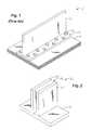
- FIG. 1is an isometric view of a conventional, prior art spar formed from dissimilar materials.
- FIG. 2is an isometric view of a structural preform constructed in accordance with the invention.
- FIG. 3is a sectional end view of the structural preform of FIG. 2 .
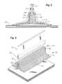
- FIG. 4is an exploded, isometric view of the structural preform of FIG. 2, a composite flange, and a metallic web.
- FIG. 5is a schematic end view of the preform, flange, and web of FIG. 4 during fabrication.
- FIG. 6is an exploded, isometric view of an alternate version of the structure of FIG. 4, a metallic flange, and a composite web.
- FIG. 7is an end view of a beam constructed from the components of FIG. 4 in accordance with the invention.
- FIG. 8is an end view of an alternate embodiment of a beam constructed in accordance with the invention.
- preform 11for a structural support beam is shown.
- preform 11When viewed from the end or in cross-section, preform 11 resembles the Greek letter ⁇ or “pi” having a longitudinal crossbar or base 13 with two longitudinal legs 15 , 17 extending therefrom. A groove or channel 19 is defined between legs 15 , 17 .
- Preform 11is a composite material that is formed by waving or braiding continuous bundles or 15 tows of structural fibers 21 (FIG. 2 ). The tows of fibers 21 are oriented to extend continuously throughout each segment of preform 11 including base 13 and legs 15 , 17 .
- the fiber preformsmay be formed to provide any desired fiber architecture needed to impart chosen load-carrying capability and to accommodate any desired web panel thickness.
- Preform 11may be impregnated with a suitable thermoset resin that acts as an adhesive to bond together two dissimilar materials.
- the resinis structurally reinforced with the filaments and/or fibers oriented in x, y, and z directions in such a manner as to provide coupling strength between the joined members.
- preform 11may be unimpregnated so that resin may be infused at a later step of the overall manufacturing process.
- preform 11is constructed by weaving or braiding the filaments in such a way that the process is not inhibited. After curing, preform 11 may be machined as needed by an appropriate method to provide desired edge straightness, smoothness, and dimensional control. Another description of preform 11 is contained in U.S. patent application Ser. No. 09/648,488, and is incorporated herein by reference.
- preform 11is used to join a flat metallic panel 31 to a flat composite plate 33 at an angle.
- Metallic plate 31has a zone 32 that is prepared for bonding to preform 11 . Preparation may be any suitable, established method appropriate to the selected metal alloy, such as chemical etching. The composite may also be prepared, in the zone to be mated with the preform, by a suitable method such as removal of a peel ply.
- metallic panel 31forms the web of a structural support member
- composite plate 33forms the flange thereof, and the angle is perpendicular.
- composite plate 33may form the web of the spar with metallic panel 31 as the flange of the spar, and the angle between the members may be acute (see FIG. 8 ).
- a beam 71has upper and lower composite flanges 73 , 75 that are inclined at a non-orthogonal angle relative to web or metallic panel 77 .
- the bases 79 of the preforms 81are substantially flat and parallel relative to flanges 73 , 75 , while the legs 83 of preforms 81 are inclined at the non-orthogonal angle relative to bases 79 .
- These conceptsare not limited to I-beam type structural support members, but may be readily adapted for use in beams having other shapes as well, such as U-shaped, C-shaped, L-shaped, or Z-shaped beams, depending on the application.
- one of the longitudinal edges of metallic panel 31is fully inserted into channel 19 of preform 11 until it bottoms out as shown in FIG. 5 or is appropriately close to bottoming out.
- the two legs 15 , 17closely receive and straddle the thickness of panel 31 .
- the vertical sides or edges of panel 31are not attached to preform 11 .
- a composite plate 33 of appropriate thickness, fiber orientation, and geometryis positioned against the base 13 of preform 11 opposite panel 31 to create a crossbar or flange for the structural support member.
- Composite plate 33may be either cured or uncured, but in the preferred embodiment of the invention, it is already cured to provide the desired configuration and dimensional tolerances in order to simplify the assembly tooling that is required.
- the fastenerless assembly of the metallic and composite elementsalso may be accomplished via the following steps.
- the base 13 of the uncured, resin-impregnated preform 11is placed at the desired joining location onto the base plate or panel (usually composite plate 33 ) after it has been suitably cleaned or prepared for bonding.
- the metallic panel 31is placed in channel 19 of uncured preform 11 at the desired angle relative to composite plate 33 .
- Appropriate boundary toolingsuch as conventional molded shapes of silicone rubber or other suitable pressure intensifier/transmitter 35 (FIG. 5 ), is positioned against each side of preform 11 .
- Vacuum bagging materials 39are placed around the resulting assembly, sealed with sealant beads 37 , and a vacuum is pulled under the bag.
- a selected resinis infused therein.
- the total structureis heated according to a thermal profile suitable for curing the thermosetting resin that impregnates preform 11 , thereby creating structural bonds that integrally link preform 11 to metallic panel 31 to create a desired structure.
- autoclave pressurecan be simultaneously applied to provide compaction of preform 11 during cure of the resin.
- the resin and the maximum cure temperaturesare selected to provide a cured glass transition temperature greater than the intended use temperature of the assembly.
- a resincan be used which has a suitable chemistry, such as free-radical polymerization, so that an energetic beam of electrons can initiate and complete the cure (a process known in the industry as electron beam curing).
- the bagging materials and positioning fixturesare removed, yielding a completed assembly.
- the curable materialsmay be uncured at the time of assembly of metallic panel 31 , preforms 11 , and composite plate 33 .
- the resin in preform 11can be injected in a resin transfer molding type of process, or infused by placing a thick layer of resin over the preform and applying a vacuum bag.
- a co-bonding of preform 11 with an uncured composite plate 33can be accomplished. Although the process was described for only one end of panel 31 , this series of steps may be performed simultaneously on both ends of panel 31 to form the end product spar or beam 41 (FIG. 7 ).
- each plate or panel 31 , 33is governed by its respective thermal expansion coefficient.
- An aluminum panel 31having an expansion coefficient of approximately 12 micro-inch/inch/degree F., will expand by about 3300 micro-inch/inch of length.
- a composite plate 33 formed from carbon fiber impregnated with epoxy resinhas negligible expansion. This difference in expansion imparts a significant strain on the joined panel and plate 31 , 33 , thereby degrading the mechanical performance of the assembly and making it difficult to achieve the desired dimensional control of the assembly because of bowing induced by the thermal mismatch.
- an axial fiber having a thermal expansion coefficient much closer to that of aluminum panel 31would reduce the amount of strain built into the assembly by the curing operation.
- an alternate embodimentdepicts a preform 51 having two (or more) types of filaments and/or fibers having different properties.
- Base filament 53which is oriented parallel to the length of the preform, is chosen such that its axial thermal expansion coefficient matches that of composite plate 33 as closely as possible.
- Leg filament 55which also is oriented parallel to the length of the preform, is chosen such that its axial thermal expansion coefficient matches that of metallic panel 31 having bonding zone 32 as closely as possible.
- Filaments 53 , 55are used in combination to provide coupling strength to the joined metallic panel 31 and composite plate 33 by being oriented parallel to the legs 57 , 59 of preform 51 (in the direction of arrow 61 ), and by being interwoven into the base 63 of preform 51 .
- the fiber or filament 53 chosen to provide coupling strengthis oriented orthogonal to the fiber and/or filaments 55 chosen for thermal expansion characteristics .
- These orthogonal fibers 53traverse the width of preform 51 , following its shape back and forth in a manner resulting from weaving of woof fibers, i.e., those fibers which are perpendicular to the lengthwise direction of the preform.
- the extent and pattern, if any, for blending the two axial fibers 53 , 55 in the area where the legs 57 , 59 intersect base 63are determined on an application-specific basis through analysis and/or empirical methods.
- a single filamentis chosen for preform 51 (FIG. 4 )
- its propertiesare selected in order to minimize its difference in thermal expansion coefficients with metallic panel 31 and composite plate 33 .
- the filamentsare oriented parallel to the axis and continuous length of the preform.
- filament or fiber selectionswould be E-glass® or S-glass® fibers for the axial direction of preform 11 , and high strength carbon fibers such as Hexcel AS4® or Toray T300® for the coupling strength direction (parallel to the vertical direction of legs 15 , 17 ).
- Glass fibersprovide a thermal expansion coefficient on the order of 6 micro-inch/inch/degree F., whereas carbon fibers have an expansion coefficient near zero.
- glass fibersare a better thermal strain match with aluminum than with carbon fiber.
- metallic filaments in the axial directionimpart a smaller difference in thermal strains between the legs 15 , 17 of preform 11 and metallic panel 31 .
- High modulus carbon fiberssuch as Hexcel IM 7 ® or Amoco T600® may be used for the coupling strength direction, where the total distance over which strain differences are multiplied is very small.
- temperatureis controlled so that the resin gels at as low a temperature as is practical. This step is followed by a slow rise in temperature to levels necessary to achieve the required glass transition temperature of the cured resin. Gelling the resin at a lower temperature aids the establishment of a stress-free temperature point that is lower than that required to achieve the needed glass transition temperature.
- the rise in temperature after gellationmust be very slow so that resin cross-link density is increased at such a rate that increasing levels of thermally-induced strain does not break down the tender bond.
- cool downpreferably occurs at as slow a rate as practical until a temperature is reached that is at least 50 degrees F. lower than the gellation temperature.
- the present inventionhas several advantages. Woven or braided pi-shaped preforms join metallic and composite plates or panels at angles relative to each other without the use of mechanical fasteners.
- the preformsprovide much greater strength than conventional adhesive bonding techniques while simplifying and reducing the cost of manufacturing.
- the present inventiondoes not require drilling, countersinking, fastener installation, or fastener head treatments. Whereas mechanical fastening involves incremental work progressing along the joint length, the present invention treats the entire joint in one step. This enables a very large reduction of 20% to 55% in the total cost of the assembly.
- the present inventionis also lighter in weight than prior art solutions because the resin-impregnated preform weighs less than the number of fasteners that would be required to provide an equivalent strength joint.
- the metallic membercan be a flat plate or panel without a flange, thereby significantly reducing the cost of fabricating the metal detail for many complex, high performance structures such as those used for aircraft.
Landscapes
- Engineering & Computer Science (AREA)
- Mechanical Engineering (AREA)
- Composite Materials (AREA)
- Chemical & Material Sciences (AREA)
- Aviation & Aerospace Engineering (AREA)
- Architecture (AREA)
- Textile Engineering (AREA)
- Thermal Sciences (AREA)
- Structural Engineering (AREA)
- Physics & Mathematics (AREA)
- Civil Engineering (AREA)
- Moulding By Coating Moulds (AREA)
- Laminated Bodies (AREA)
- Lining Or Joining Of Plastics Or The Like (AREA)
- Body Structure For Vehicles (AREA)
- Piezo-Electric Or Mechanical Vibrators, Or Delay Or Filter Circuits (AREA)
- Flanged Joints, Insulating Joints, And Other Joints (AREA)
- Rod-Shaped Construction Members (AREA)
- Connection Of Plates (AREA)
- Standing Axle, Rod, Or Tube Structures Coupled By Welding, Adhesion, Or Deposition (AREA)
Abstract
Description
The following U.S. Patent Applications by the same inventor, Elbert L. McKague, Jr. are being simultaneously filed and incorporated herein by reference: U.S. Patent Application entitled “Apparatus And Method For Controlled Damage Of Conformable Materials”; U.S. Patent Application entitled “Composite Structural Panel with Undulated Body”; and by the same inventor together with inventors Ronald P. Schmidt and David T. Uhl, U.S. Patent Application entitled “Composite Material Support Structures With Sinusoidal Webs And Method Of Fabricating Same”.
1. Technical Field
The present invention relates in general to an improved structural member, and in particular to an improved structural beam, made by joining dissimilar materials. Still more particularly, the present invention relates to a structural composite preform for joining the web of a structure with flanges formed from dissimilar materials.
2. Description of the Prior Art
Structural support spars or I-beams typically have an “I” or “H” shaped cross-section, having a web with a crossbar or flange on each end of the web. The web and flanges extend integrally down the length of the beam, but may vary in shape, thickness, materials, etc. For example, one type of beam has a web formed from a first material (such as a metal) and flanges formed from a second, dissimilar material (such as a composite material). This type of beam has been pursued through a variety of design and manufacturing approaches since these structures offer the potential of providing excellent stiffness and strength-to-weight performance.
Prior approaches to joining dissimilar materials such as metals and composites have generally relied on mechanical fastening if the two elements are at an angle. As shown in FIG. 1, aspar 11 having an inverted T-shaped metal panel 13 with aflange 15 is joined to aflat composite plate 17 withmechanical fasteners 19 such thatmetal panel 13 andcomposite plate 17 are perpendicular to each other. In such an arrangement,metal panel 13 must haveflange 15 to enable fastening tocomposite plate 17. Moreover, the necessity of havingflange 15 onmetal panel 13 adds considerable cost to its fabrication sinceflange 15 significantly increases the volume of metal that must be purchased and then machined away. In addition, mechanical fastening involves drilling and countersinking holes, installing fasteners and, in some cases, treating the fastener heads to achieve a desired surface smoothness. These steps are expensive and can contribute an additional 25% to 60% to the overall cost of the spar assembly. Thus, an improved apparatus and method for forming a structural support member by joining dissimilar materials at an angle is needed.
A preformed component or “preform” for a structural support beam has a planar base with two longitudinal legs extending in parallel therefrom. A channel is defined between the legs of the preform, and a flat panel that forms the web of the structural support beam is inserted into the channel. The preform is a composite material having continuous filaments of woven or braided fiber. The preform is impregnated with a thermoset resin that joins and bonds the web to the flange of the structural support beam. The preform provides excellent structural support even if the web and the flange are formed from dissimilar materials such as metal and composite. The resin is structurally reinforced with oriented fibers in such a manner as to provide coupling strength between the joined members.
When a single filament is chosen for the preform, its properties are selected to minimize the difference in thermal expansion coefficients of the metal web and the composite flange. However, the preform may have two or more types of filaments with different properties. The filament in the base of the preform is chosen such that its axial thermal expansion coefficient matches that of the composite flange. The filament in the legs of the preform is chosen such that its axial thermal expansion coefficient matches that of the metal web. These filaments are used in combination to provide coupling strength between the joined metal web and composite flange by having the best structural fiber oriented parallel to the legs of the preform, and by its being interwoven into the base of the preform.
The foregoing and other objects and advantages of the present invention will be apparent to those skilled in the art, in view of the following detailed description of the preferred embodiment of the present invention, taken in conjunction with the appended claims and the accompanying drawings.
So that the manner in which the features, advantages and objects of the invention, as well as others which will become apparent, are attained and can be understood in more detail, more particular description of the invention briefly summarized above may be had by reference to the embodiment thereof which is illustrated in the appended drawings, which drawings form a part of this specification. It is to be noted, however, that the drawings illustrate only a preferred embodiment of the invention and is therefore not to be considered limiting of its scope as the invention may admit to other equally effective embodiments.
FIG. 1 is an isometric view of a conventional, prior art spar formed from dissimilar materials.
FIG. 2 is an isometric view of a structural preform constructed in accordance with the invention.
FIG. 3 is a sectional end view of the structural preform of FIG.2.
FIG. 4 is an exploded, isometric view of the structural preform of FIG. 2, a composite flange, and a metallic web.
FIG. 5 is a schematic end view of the preform, flange, and web of FIG. 4 during fabrication.
FIG. 6 is an exploded, isometric view of an alternate version of the structure of FIG. 4, a metallic flange, and a composite web.
FIG. 7 is an end view of a beam constructed from the components of FIG. 4 in accordance with the invention.
FIG. 8 is an end view of an alternate embodiment of a beam constructed in accordance with the invention.
Referring to FIGS. 2 and 3, a preformed component or “preform”11 for a structural support beam is shown. When viewed from the end or in cross-section, preform11 resembles the Greek letter π or “pi” having a longitudinal crossbar orbase 13 with twolongitudinal legs channel 19 is defined betweenlegs fibers 21 are oriented to extend continuously throughout each segment ofpreform 11 includingbase 13 andlegs
Alternatively, preform11 may be unimpregnated so that resin may be infused at a later step of the overall manufacturing process. In the latter embodiment,preform 11 is constructed by weaving or braiding the filaments in such a way that the process is not inhibited. After curing, preform11 may be machined as needed by an appropriate method to provide desired edge straightness, smoothness, and dimensional control. Another description ofpreform 11 is contained in U.S. patent application Ser. No. 09/648,488, and is incorporated herein by reference.
Referring now to FIG. 4,preform 11 is used to join a flatmetallic panel 31 to aflat composite plate 33 at an angle.Metallic plate 31 has azone 32 that is prepared for bonding to preform11. Preparation may be any suitable, established method appropriate to the selected metal alloy, such as chemical etching. The composite may also be prepared, in the zone to be mated with the preform, by a suitable method such as removal of a peel ply. In the embodiment shown,metallic panel 31 forms the web of a structural support member,composite plate 33 forms the flange thereof, and the angle is perpendicular. However,composite plate 33 may form the web of the spar withmetallic panel 31 as the flange of the spar, and the angle between the members may be acute (see FIG.8). The members can be joined at other angles relative to each other because thefibrous preform 11 is flexible prior to curing the resin. In FIG. 8, abeam 71 has upper and lowercomposite flanges metallic panel 77. Thebases 79 of thepreforms 81 are substantially flat and parallel relative toflanges legs 83 ofpreforms 81 are inclined at the non-orthogonal angle relative to bases79. These concepts are not limited to I-beam type structural support members, but may be readily adapted for use in beams having other shapes as well, such as U-shaped, C-shaped, L-shaped, or Z-shaped beams, depending on the application.
During assembly, one of the longitudinal edges ofmetallic panel 31 is fully inserted intochannel 19 ofpreform 11 until it bottoms out as shown in FIG. 5 or is appropriately close to bottoming out. The twolegs panel 31. The vertical sides or edges ofpanel 31 are not attached to preform11. Next, acomposite plate 33 of appropriate thickness, fiber orientation, and geometry is positioned against thebase 13 ofpreform 11opposite panel 31 to create a crossbar or flange for the structural support member.Composite plate 33 may be either cured or uncured, but in the preferred embodiment of the invention, it is already cured to provide the desired configuration and dimensional tolerances in order to simplify the assembly tooling that is required.
The fastenerless assembly of the metallic and composite elements also may be accomplished via the following steps. (1) Thebase 13 of the uncured, resin-impregnatedpreform 11 is placed at the desired joining location onto the base plate or panel (usually composite plate33) after it has been suitably cleaned or prepared for bonding. (2) Using appropriate fixtures, themetallic panel 31 is placed inchannel 19 ofuncured preform 11 at the desired angle relative tocomposite plate 33. (3) Appropriate boundary tooling, such as conventional molded shapes of silicone rubber or other suitable pressure intensifier/transmitter35 (FIG.5), is positioned against each side ofpreform 11. (4)Vacuum bagging materials 39 are placed around the resulting assembly, sealed withsealant beads 37, and a vacuum is pulled under the bag. If the preform was previously unimpregnated, a selected resin is infused therein. (5) The total structure is heated according to a thermal profile suitable for curing the thermosetting resin that impregnatespreform 11, thereby creating structural bonds that integrally linkpreform 11 tometallic panel 31 to create a desired structure. If desired or required, autoclave pressure can be simultaneously applied to provide compaction ofpreform 11 during cure of the resin. The resin and the maximum cure temperatures are selected to provide a cured glass transition temperature greater than the intended use temperature of the assembly. Alternatively, a resin can be used which has a suitable chemistry, such as free-radical polymerization, so that an energetic beam of electrons can initiate and complete the cure (a process known in the industry as electron beam curing). (6) Following completion of the required cure cycle, the bagging materials and positioning fixtures are removed, yielding a completed assembly.
Alternatively, it should be readily apparent to one skilled in the art that all of the curable materials may be uncured at the time of assembly ofmetallic panel 31, preforms11, andcomposite plate 33. After the respective components are assembled and placed in suitable tooling, the resin inpreform 11 can be injected in a resin transfer molding type of process, or infused by placing a thick layer of resin over the preform and applying a vacuum bag. Although this reduces the number of cure cycles required, it significantly complicates the assembly cure tooling requirements, thereby increasing both cost and risk. By still another means, a co-bonding ofpreform 11 with an uncuredcomposite plate 33 can be accomplished. Although the process was described for only one end ofpanel 31, this series of steps may be performed simultaneously on both ends ofpanel 31 to form the end product spar or beam41 (FIG.7).
Depending upon the actual use temperature of the assembly and the chemistry of the selected resin, it may be necessary to expose the assembly to resin cure temperatures as high as 350 degrees F. At such temperatures, the dimensional growth of each plate orpanel aluminum panel 31, having an expansion coefficient of approximately 12 micro-inch/inch/degree F., will expand by about 3300 micro-inch/inch of length. In contrast, acomposite plate 33 formed from carbon fiber impregnated with epoxy resin has negligible expansion. This difference in expansion imparts a significant strain on the joined panel andplate legs preform 11, an axial fiber having a thermal expansion coefficient much closer to that ofaluminum panel 31 would reduce the amount of strain built into the assembly by the curing operation.
In FIG. 6, an alternate embodiment depicts apreform 51 having two (or more) types of filaments and/or fibers having different properties.Base filament 53, which is oriented parallel to the length of the preform, is chosen such that its axial thermal expansion coefficient matches that ofcomposite plate 33 as closely as possible.Leg filament 55, which also is oriented parallel to the length of the preform, is chosen such that its axial thermal expansion coefficient matches that ofmetallic panel 31 havingbonding zone 32 as closely as possible.Filaments metallic panel 31 andcomposite plate 33 by being oriented parallel to thelegs base 63 ofpreform 51. The fiber orfilament 53 chosen to provide coupling strength is oriented orthogonal to the fiber and/orfilaments 55 chosen for thermal expansion characteristics . Theseorthogonal fibers 53 traverse the width ofpreform 51, following its shape back and forth in a manner resulting from weaving of woof fibers, i.e., those fibers which are perpendicular to the lengthwise direction of the preform.
The extent and pattern, if any, for blending the twoaxial fibers legs base 63 are determined on an application-specific basis through analysis and/or empirical methods. When a single filament is chosen for preform51 (FIG.4), its properties are selected in order to minimize its difference in thermal expansion coefficients withmetallic panel 31 andcomposite plate 33. However, in all cases the filaments are oriented parallel to the axis and continuous length of the preform.
An example of filament or fiber selections would be E-glass® or S-glass® fibers for the axial direction ofpreform 11, and high strength carbon fibers such as Hexcel AS4® or Toray T300® for the coupling strength direction (parallel to the vertical direction oflegs 15,17). Glass fibers provide a thermal expansion coefficient on the order of 6 micro-inch/inch/degree F., whereas carbon fibers have an expansion coefficient near zero. Thus, glass fibers are a better thermal strain match with aluminum than with carbon fiber. Alternatively, metallic filaments in the axial direction impart a smaller difference in thermal strains between thelegs preform 11 andmetallic panel 31. High modulus carbon fibers such as Hexcel IM7® or Amoco T600® may be used for the coupling strength direction, where the total distance over which strain differences are multiplied is very small.
During the cure of the resin, temperature is controlled so that the resin gels at as low a temperature as is practical. This step is followed by a slow rise in temperature to levels necessary to achieve the required glass transition temperature of the cured resin. Gelling the resin at a lower temperature aids the establishment of a stress-free temperature point that is lower than that required to achieve the needed glass transition temperature. The rise in temperature after gellation must be very slow so that resin cross-link density is increased at such a rate that increasing levels of thermally-induced strain does not break down the tender bond. After completing the maximum temperature dwell, cool down preferably occurs at as slow a rate as practical until a temperature is reached that is at least 50 degrees F. lower than the gellation temperature. This slow cool down allows some relaxation to occur in the polymer and helps to preserve the lowest possible stress-free temperature. The difference in stress-free temperature and ambient temperature, multiplied by the difference between thermal expansion coefficient ofmetallic panel 31 and that of the axial fibers inpreform 11, determine the amount of thermally-induced strain in the resulting assembly.
The present invention has several advantages. Woven or braided pi-shaped preforms join metallic and composite plates or panels at angles relative to each other without the use of mechanical fasteners. The preforms provide much greater strength than conventional adhesive bonding techniques while simplifying and reducing the cost of manufacturing. The present invention does not require drilling, countersinking, fastener installation, or fastener head treatments. Whereas mechanical fastening involves incremental work progressing along the joint length, the present invention treats the entire joint in one step. This enables a very large reduction of 20% to 55% in the total cost of the assembly. In addition, the present invention is also lighter in weight than prior art solutions because the resin-impregnated preform weighs less than the number of fasteners that would be required to provide an equivalent strength joint. Moreover, the metallic member can be a flat plate or panel without a flange, thereby significantly reducing the cost of fabricating the metal detail for many complex, high performance structures such as those used for aircraft.
While the invention has been shown or described in only some of its forms, it should be apparent to those skilled in the art that it is not so limited, but is susceptible to various changes without departing from the scope of the invention.
Claims (24)
1. A structural member, comprising:
a web formed from one of a metallic material and a composite material, the web having a pair of longitudinal edges extending in an axial direction;
a flange formed from the other of the metallic and composite materials;
a preform formed from composite materials and having a base with a pair of axially elongated legs extending therefrom to define a channel therebetween, wherein the preform is formed from filaments that extend through the base and legs; and wherein
one of the longitudinal edges of the web is bonded in the channel of the preform and the flange is bonded to a surface of the base of the preform.
2. The structural member ofclaim 1 wherein the axial filaments minimize a difference in thermal expansion coefficients of the web and the flange.
3. The structural member ofclaim 1 wherein the preform has a pi-shaped cross-section.
4. The structural member ofclaim 1 wherein the axial filaments are oriented parallel to an axial, continuous length of the preform.
5. The structural member ofclaim 1 wherein the flange and the base of the preform are inclined at a non-orthogonal angle relative to the web.
6. The structural member ofclaim 1 wherein the preform is impregnated with a thermoset resin that acts as an adhesive to bond together the web and the flange.
7. The structural member ofclaim 6 wherein the resin is structurally reinforced with fibers to provide coupling strength between the web and the flange.
8. The structural member ofclaim 1 wherein the preform has a first type of axial filament in the base, and a second type of axial filament in the legs.
9. The structural member ofclaim 8 wherein the first and second types of axial filaments are blended in an area where the legs intersect the base.
10. The structural member ofclaim 8 wherein the first type of axial filament has an axial thermal expansion coefficient that substantially matches an axial thermal expansion coefficient of the flange, and wherein the second type of axial filament has an axial thermal expansion coefficient that substantially matches an axial thermal expansion coefficient of the web.
11. A structural member, comprising:
a web formed from one of a metallic material and a composite material, the web having a pair of longitudinal edges extending in an axial direction;
a flange formed from the other of the metallic and composite materials;
a generally pi-shaped preform formed from composite materials and having a base with a pair of axially elongated legs extending therefrom to define a channel therebetween, the preform being formed from axial filaments that extend through the base and legs, wherein the axial filaments are oriented parallel to the axial direction and a continuous length of the preform, and the axial filaments minimize a difference in thermal expansion coefficients of the web and the flange; and wherein
one of the longitudinal edges of the web is bonded in the channel of the preform and the flange is bonded to a surface of the base of the preform.
12. The structural member ofclaim 11 wherein the flange and the base of the preform are inclined at a non-orthogonal angle relative to the web.
13. The structural member ofclaim 11 wherein the preform is impregnated with a thermoset resin that acts as an adhesive to bond together the web and the flange.
14. The structural member ofclaim 13 wherein the resin is structurally reinforced with fibers to provide coupling strength between the web and the flange.
15. The structural member ofclaim 11 wherein the preform has a first type of axial filament in the base, and a second type of axial filament in the legs, and wherein the first and second types of axial filaments are blended in an area where the legs intersect the base.
16. The structural member ofclaim 15 wherein the first type of axial filament has an axial thermal expansion coefficient that substantially matches an axial thermal expansion coefficient of the flange, and the second type of axial filament has an axial thermal expansion coefficient that substantially matches an axial thermal expansion coefficient of the web.
17. A method for fabricating a structural member, comprising the steps of:
(a) providing a web formed from one of a metallic material and a composite material and having a longitudinal edge extending in an axial direction, and a flange formed from the other of the metallic and composite materials;
(b) forming a preform from composite materials, the preform having a base with a pair of legs extending therefrom to define a channel therebetween, wherein the preform has filaments that extend through the base and the legs;
(c) positioning boundary tooling on the preform, web, and flange and heating the structural member;
(d) bonding the longitudinal edge of the web in the channel of the preform such that the legs of the preform closely receive the web; and
(e) bonding the base of the preform to the flange to form a structural member.
18. The method ofclaim 17 wherein steps (d) and (e) comprises heating the web, flange, and preform to create structural bonds therebetween.
19. The method ofclaim 17 , further comprising the step of impregnating the preform with a thermoset resin.
20. The method ofclaim 17 wherein the preform of step (b) is unimpregnated, and further comprising the step of infusing or injecting the unimpregnated preform with resin.
21. The method ofclaim 17 , further comprising the step of applying autoclave pressure to provide compaction of the preform.
22. The method ofclaim 17 , further comprising the step of curing said one of the web and the flange formed from the composite material.
23. The method ofclaim 17 wherein step (c) comprises placing a sealed pressure intensifier over the preform inside a vacuum bag.
24. The method ofclaim 17 , further comprising the step of inclining the web of the preform at a non-orthogonal angle relative to the flange and the base of the preform.
Priority Applications (11)
| Application Number | Priority Date | Filing Date | Title |
|---|---|---|---|
| US09/648,321US6374570B1 (en) | 2000-08-25 | 2000-08-25 | Apparatus and method for joining dissimilar materials to form a structural support member |
| CA002419444ACA2419444C (en) | 2000-08-25 | 2001-08-23 | Apparatus and method for joining dissimilar materials to form a structural support member |
| DE60115914TDE60115914T2 (en) | 2000-08-25 | 2001-08-23 | DEVICE AND METHOD FOR CONNECTING DIFFERENT MATERIALS OF A SUPPORTING ELEMENT |
| KR10-2003-7002493AKR20030029832A (en) | 2000-08-25 | 2001-08-23 | Apparatus and method for joining dissimilar materials to form a structural support member |
| AU8720801AAU8720801A (en) | 2000-08-25 | 2001-08-23 | Apparatus and method for joining dissimilar materials to form a structural support member |
| PCT/US2001/041854WO2002016784A2 (en) | 2000-08-25 | 2001-08-23 | Apparatus and method for joining dissimilar materials to form a structural support member |
| EP01966721AEP1311768B1 (en) | 2000-08-25 | 2001-08-23 | Apparatus and method for joining dissimilar materials to form a structural support member |
| AU2001287208AAU2001287208C1 (en) | 2000-08-25 | 2001-08-23 | Apparatus and method for joining dissimilar materials to form a structural support member |
| JP2002521847AJP2004507629A (en) | 2000-08-25 | 2001-08-23 | Apparatus and method for joining dissimilar materials to form a structural support member |
| AT01966721TATE313017T1 (en) | 2000-08-25 | 2001-08-23 | DEVICE AND METHOD FOR CONNECTING DIFFERENT MATERIALS OF A SUPPORT ELEMENT |
| US10/025,393US6718713B2 (en) | 2000-08-25 | 2001-12-19 | Apparatus and method for joining dissimilar materials to form a structural support member |
Applications Claiming Priority (1)
| Application Number | Priority Date | Filing Date | Title |
|---|---|---|---|
| US09/648,321US6374570B1 (en) | 2000-08-25 | 2000-08-25 | Apparatus and method for joining dissimilar materials to form a structural support member |
Related Child Applications (1)
| Application Number | Title | Priority Date | Filing Date |
|---|---|---|---|
| US10/025,393Continuation-In-PartUS6718713B2 (en) | 2000-08-25 | 2001-12-19 | Apparatus and method for joining dissimilar materials to form a structural support member |
Publications (1)
| Publication Number | Publication Date |
|---|---|
| US6374570B1true US6374570B1 (en) | 2002-04-23 |
Family
ID=24600330
Family Applications (2)
| Application Number | Title | Priority Date | Filing Date |
|---|---|---|---|
| US09/648,321Expired - LifetimeUS6374570B1 (en) | 2000-08-25 | 2000-08-25 | Apparatus and method for joining dissimilar materials to form a structural support member |
| US10/025,393Expired - LifetimeUS6718713B2 (en) | 2000-08-25 | 2001-12-19 | Apparatus and method for joining dissimilar materials to form a structural support member |
Family Applications After (1)
| Application Number | Title | Priority Date | Filing Date |
|---|---|---|---|
| US10/025,393Expired - LifetimeUS6718713B2 (en) | 2000-08-25 | 2001-12-19 | Apparatus and method for joining dissimilar materials to form a structural support member |
Country Status (9)
| Country | Link |
|---|---|
| US (2) | US6374570B1 (en) |
| EP (1) | EP1311768B1 (en) |
| JP (1) | JP2004507629A (en) |
| KR (1) | KR20030029832A (en) |
| AT (1) | ATE313017T1 (en) |
| AU (2) | AU2001287208C1 (en) |
| CA (1) | CA2419444C (en) |
| DE (1) | DE60115914T2 (en) |
| WO (1) | WO2002016784A2 (en) |
Cited By (69)
| Publication number | Priority date | Publication date | Assignee | Title |
|---|---|---|---|---|
| US20020053175A1 (en)* | 2000-08-25 | 2002-05-09 | Mckague Elbert Lee | Apparatus and method for joining dissimilar materials to form a structural support member |
| US20020185785A1 (en)* | 2001-06-11 | 2002-12-12 | The Boeing Company | Resin infusion mold tool system and vacuum assisted resin transfer molding with subsequent pressure bleed |
| US20030000641A1 (en)* | 2001-07-02 | 2003-01-02 | Schmidt Ronald P. | Adhesive-infused 3-D woven textile preforms for structural joints |
| US6550211B2 (en)* | 1999-07-05 | 2003-04-22 | Recherche & Developpement Du Groupe Cockerill Sambre | Girder structure and method for producing such structures |
| US20030106276A1 (en)* | 2001-12-07 | 2003-06-12 | Tallman Van S. | Ceiling tile support system and method |
| US6676882B2 (en)* | 2001-08-28 | 2004-01-13 | Lockheed Martin Corporation | Methods of hot-melt resin impregnation of 3-D, woven, textile preforms |
| US20040011927A1 (en)* | 2002-07-19 | 2004-01-22 | Christman David B. | Apparatuses and methods for joining structural members, such as composite structural members |
| EP1365081A3 (en)* | 2002-05-23 | 2004-12-15 | Rohr, Inc. | Structural element with rib-receiving member |
| US6849150B1 (en)* | 2001-01-16 | 2005-02-01 | Lockheed Martin Corporation | System and method of forming structural assemblies with 3-D woven joint pre-forms |
| US6863767B2 (en)* | 2001-08-23 | 2005-03-08 | Lockheed Martin Corporation | Paste-bond clevis joint |
| US20050064134A1 (en)* | 2003-04-24 | 2005-03-24 | Brantley Jerry W. | Apparatus, system, and method of joining structural components with a tapered tension bond joint |
| US20060113451A1 (en)* | 2004-11-30 | 2006-06-01 | The Boeing Company | Minimum bond thickness assembly feature assurance |
| US20060113450A1 (en)* | 2004-11-30 | 2006-06-01 | The Boeing Company | Self-locating feature for a pi-joint assembly |
| US20060115320A1 (en)* | 2004-11-30 | 2006-06-01 | The Boeing Company | Determinant assembly features for vehicle structures |
| US20060121809A1 (en)* | 2004-12-08 | 2006-06-08 | Jonathan Goering | Three-dimensional woven integrally stiffened panel |
| US20060240220A1 (en)* | 2005-04-07 | 2006-10-26 | The Boeing Company | Composite-to-metal joint |
| US20060237588A1 (en)* | 2005-03-31 | 2006-10-26 | The Boeing Company | Composite structural member having an undulating web and method for forming the same |
| WO2006127372A1 (en)* | 2005-05-25 | 2006-11-30 | The Boeing Company | Methods of joining structures and joints formed thereby |
| US20060283133A1 (en)* | 2005-06-17 | 2006-12-21 | The Boeing Company | Composite reinforcement of metallic structural elements |
| WO2007003372A1 (en)* | 2005-06-30 | 2007-01-11 | Airbus Deutschland Gmbh | Process for producing a substantially shell-shaped component |
| US20070120288A1 (en)* | 2005-11-29 | 2007-05-31 | Lockheed Martin | System, method, and apparatus for production-worthy, low cost composite tool fabrication |
| US7238409B1 (en) | 2002-05-23 | 2007-07-03 | Rohr, Inc. | Structural element with rib-receiving member |
| US20080105661A1 (en)* | 2006-11-02 | 2008-05-08 | The Boeing Company | Method and apparatus to construct metal securement member for an aircraft |
| US20080131656A1 (en)* | 2006-12-05 | 2008-06-05 | Lockheed Martin Corporation | System, method, and apparatus for structural lug formed from a combination of metal and composite laminate materials |
| US20090039208A1 (en)* | 2005-06-07 | 2009-02-12 | Bernd Raeckers | Method for manufacturing a reinforced shell for forming component parts for aircraft and shell for component parts for aircraft |
| US20090247034A1 (en)* | 2008-03-31 | 2009-10-01 | Jonathan Goering | Fiber Architecture for Pi-Preforms |
| US20090272848A1 (en)* | 2006-03-27 | 2009-11-05 | Andrew Robert Munday | Aircraft Component |
| US20100012787A1 (en)* | 2008-07-18 | 2010-01-21 | Michael Leslie Hand | Strong bonded joints for cryogenic application |
| US20100105269A1 (en)* | 2008-10-29 | 2010-04-29 | Jonathan Goering | Pi-Shaped Preform |
| US20100105268A1 (en)* | 2008-10-29 | 2010-04-29 | Kenneth Ouellette | Pi-Preform with Variable Width Clevis |
| US20100135815A1 (en)* | 2009-02-20 | 2010-06-03 | General Electric Company | Spar cap for wind turbine blades |
| US20100135818A1 (en)* | 2009-12-01 | 2010-06-03 | Achuthan Babu | Systems and methods of assembling a rotor blade for use in a wind turbine |
| US20100147460A1 (en)* | 2006-12-13 | 2010-06-17 | European Aeronautic Defence And Space Company Eads France | Process for manufacturing a complex piece made of composite material with long fibers and thermosetting matrix |
| US20100162567A1 (en)* | 2006-11-02 | 2010-07-01 | The Boeing Company | Mounting device for an aircraft |
| US20100167007A1 (en)* | 2008-12-30 | 2010-07-01 | Jonathan Goering | Woven Preform with Integral Off Axis Stiffeners |
| US20110036495A1 (en)* | 2007-08-10 | 2011-02-17 | European Aeronautic Defence And Space Company Eads France | Method of manufacturing a complex structure made of a composite by assembling rigid components |
| US20110219719A1 (en)* | 2010-03-10 | 2011-09-15 | Israel Stol | Transition-joints for joining dissimilar materials |
| US20110229333A1 (en)* | 2010-03-22 | 2011-09-22 | Repower Systems Ag | Shear web connection |
| US20120018587A1 (en)* | 2010-07-22 | 2012-01-26 | The Boeing Company | Fabric Preform Insert for a Composite Tank Y-Joint |
| US20120132745A1 (en)* | 2010-11-26 | 2012-05-31 | Airbus Operations Gmbh | Support strut for the support of a floor structure of an aircraft |
| US20120135200A1 (en)* | 2010-11-29 | 2012-05-31 | Burvill Thomas | Aircraft panel structure and aircraft panel structure manufacturing method for alleviation of stress |
| CN103507942A (en)* | 2012-06-20 | 2014-01-15 | 波音公司 | Composite structural panels and aircraft fuselages |
| EP2273103A3 (en)* | 2009-07-07 | 2014-04-30 | Nordex Energy GmbH | Rotor blade for a wind turbine and method for its manufacture |
| US8939407B2 (en) | 2011-02-15 | 2015-01-27 | The Boeing Company | Common bulkhead for composite propellant tanks |
| US8985515B2 (en) | 2010-12-28 | 2015-03-24 | Textron Innovations Inc. | Multi-directional load joint system |
| WO2015142171A1 (en)* | 2014-03-17 | 2015-09-24 | Gtm Holding B.V. | Primary structure connecting element for aircraft and method for manufacturing the connecting element |
| NL2012457A (en)* | 2013-07-16 | 2015-12-03 | Gtm Holding B V | Primary structure connecting element for aircraft and method for manufacturing the connecting element. |
| US9279531B2 (en) | 2012-12-17 | 2016-03-08 | United Technologies Corporation | Composite ducts and methods |
| US20160244140A1 (en)* | 2013-10-02 | 2016-08-25 | Mitsubishi Heavy Industries, Ltd. | Joint, and aircraft structure |
| US9453293B2 (en) | 2008-07-18 | 2016-09-27 | The Boeing Company | Method of making a composite tank having joint with softening strip |
| US20170029154A1 (en)* | 2015-07-27 | 2017-02-02 | Arthur Julius Beutler | Bag opener component for plastic bag dispenser |
| US20170157474A1 (en)* | 2015-12-07 | 2017-06-08 | Nike, Inc. | Golf club head including mechanical and adhesive joints |
| DE102016210123A1 (en)* | 2016-06-08 | 2017-12-14 | Airbus Operations Gmbh | Stiffening component for a structure of an aircraft or spacecraft, aircraft or spacecraft, and method |
| US20180029689A1 (en)* | 2016-07-26 | 2018-02-01 | Embraer S.A. | Fiber metal laminate reinforced wing spar for retractable underwing mounted landing gear assemblies |
| US10040538B2 (en) | 2013-10-02 | 2018-08-07 | Mitsubishi Heavy Industries, Ltd. | Joint, and aircraft structure |
| US20190071163A1 (en)* | 2017-09-05 | 2019-03-07 | The Boeing Company | Energy-absorbing under-floor airframe |
| CN109835465A (en)* | 2017-11-24 | 2019-06-04 | 空中客车运营有限公司 | Manufacturing method, frame parts and the door frame structure of the frame parts of the door frame structure of aircraft |
| US10323667B2 (en)* | 2016-03-15 | 2019-06-18 | Hyundai Motor Company | Composite product with junction structure |
| US10351229B2 (en)* | 2014-05-15 | 2019-07-16 | Sikorsky Aircraft Corporation | Metallic dimpled doubler |
| US10399709B2 (en) | 2008-07-18 | 2019-09-03 | The Boeing Company | Method of making a device for controlling stress in joints at cryogenic temperatures |
| US10730247B2 (en)* | 2013-12-03 | 2020-08-04 | Lm Wp Patent Holding A/S | Method of manufacturing a shear web using a pre-formed web foot flange |
| US10751932B2 (en)* | 2017-07-21 | 2020-08-25 | Wisconsin Alumni Research Foundation | Joint structures |
| US20200353715A1 (en)* | 2019-05-09 | 2020-11-12 | The Boeing Company | Composite Structure Having a Variable Gage and Methods for Forming a Composite Structure Having a Variable Gage |
| US10889364B1 (en)* | 2017-09-15 | 2021-01-12 | Northrop Grumman Systems Corporation | Aircraft full depth pi preform joints |
| US10913215B2 (en)* | 2019-05-09 | 2021-02-09 | The Boeing Company | Composite structure having a variable gage and methods for forming a composite structure having a variable gage |
| US10919256B2 (en)* | 2019-05-09 | 2021-02-16 | The Boeing Company | Composite structure having a variable gage and methods for forming a composite structure having a variable gage |
| US11131289B2 (en)* | 2016-06-28 | 2021-09-28 | Vestas Wind Systems A/S | Manufacture of a wind turbine blade |
| US11326576B2 (en)* | 2017-07-27 | 2022-05-10 | Vestas Wind Systems A/S | Web foot for a shear web |
| US12377950B2 (en) | 2019-04-12 | 2025-08-05 | Ihi Aerospace Co., Ltd. | Joint structure and assembly method for same |
Families Citing this family (47)
| Publication number | Priority date | Publication date | Assignee | Title |
|---|---|---|---|---|
| US6964723B2 (en)* | 2002-10-04 | 2005-11-15 | The Boeing Company | Method for applying pressure to composite laminate areas masked by secondary features |
| US6976343B2 (en)* | 2003-04-24 | 2005-12-20 | Mcgushion Kevin D | Compressive flange sinusoidal structural member |
| FR2855496B1 (en)* | 2003-05-27 | 2006-09-22 | Snecma Moteurs | REAR SUSPENSION OF AIRCRAFT ENGINE WITH PUSH REPEAT |
| DE10351701A1 (en)* | 2003-11-03 | 2005-05-25 | Enno Roggemann Gmbh & Co. Kg | Method for joining vehicle components by form fitting as well as by gluing, using particularly precisely matching parts |
| US7080805B2 (en)* | 2004-05-05 | 2006-07-25 | The Boeing Company | Stiffened structures and associated methods |
| FR2873347B1 (en)* | 2004-07-22 | 2006-11-17 | Airbus France Sas | DEVICE FOR LAUNCHING ELEMENTS OF COMPOSITE STRUCTURE WITH METALLIC STRUCTURE ELEMENTS |
| US7258828B2 (en)* | 2004-09-03 | 2007-08-21 | Lockheed Martin Corporation | Infusion joining of composite structures |
| KR100597070B1 (en)* | 2004-10-27 | 2006-07-05 | 한국건설기술연구원 | Hybrid Steel-Glass Beam |
| KR100647471B1 (en)* | 2004-12-23 | 2006-11-23 | 한국건설기술연구원 | Production method of composite stud and composite stud manufactured by the above method |
| US7959058B1 (en)* | 2005-01-13 | 2011-06-14 | The United States Of America As Represented By The Secretary Of The Navy | Hybrid composite welded joint |
| US8444087B2 (en) | 2005-04-28 | 2013-05-21 | The Boeing Company | Composite skin and stringer structure and method for forming the same |
| US7740932B2 (en) | 2005-03-31 | 2010-06-22 | The Boeing Company | Hybrid fiberglass composite structures and methods of forming the same |
| US7721495B2 (en) | 2005-03-31 | 2010-05-25 | The Boeing Company | Composite structural members and methods for forming the same |
| US7467763B2 (en) | 2005-06-03 | 2008-12-23 | Kismarton Max U | Composite landing gear apparatus and methods |
| US7818945B2 (en)* | 2005-03-31 | 2010-10-26 | The Boeing Company | Composite structural member having an undulating web and method for forming same |
| US7748119B2 (en) | 2005-06-03 | 2010-07-06 | The Boeing Company | Method for manufacturing composite components |
| DE102005034621B3 (en)* | 2005-07-19 | 2007-01-11 | Deutsches Zentrum für Luft- und Raumfahrt e.V. | Composite structure of fiber-reinforced thermoplastics, e.g. slat with reinforcing rib, comprises first component welded to second component with endless fiber-reinforced and staple fiber-reinforced parts |
| FR2896770B1 (en)* | 2006-01-27 | 2008-04-11 | Eurocopter France | SIDE-HOLDING ANTI-CRASH COMPOSITE STRUCTURE FOR AIRCRAFT. |
| FR2896768B1 (en)* | 2006-01-27 | 2009-10-09 | Eurocopter France | CONTROLLED FLAMBING ANTI-CRASH COMPOSITE STRUCTURE FOR AIRCRAFT. |
| US7611595B2 (en)* | 2006-02-01 | 2009-11-03 | Lockheed Martin Corporation | System, method, and apparatus for metallic-composite joint with compliant, non-corrosive interface |
| US8166721B1 (en)* | 2006-02-21 | 2012-05-01 | The Steel Network, Inc. | Metal-wood structural member |
| US7670527B2 (en)* | 2006-05-09 | 2010-03-02 | Lockheed Martin Corporation | Failsafe injected adhesive joint |
| US7790294B2 (en)* | 2006-07-05 | 2010-09-07 | Lockheed Martin Corporation | System, method, and apparatus for three-dimensional woven metal preform structural joint |
| US8910908B2 (en)* | 2006-10-31 | 2014-12-16 | Airbus Operations Gmbh | Two-piece stiffening element |
| JP4327839B2 (en)* | 2006-12-13 | 2009-09-09 | 本田技研工業株式会社 | Assembly method for aluminum alloy wings |
| US8082667B2 (en)* | 2007-05-31 | 2011-12-27 | The Boeing Company | Apparatus and methods for securing a first structural member and a second structural member to one another |
| CA2723862C (en)* | 2008-05-16 | 2017-03-21 | Xemc Darwind B.V. | Method of manufacturing a turbine blade |
| FR2953158B1 (en)* | 2009-11-30 | 2012-01-20 | Airbus Operations Sas | METHOD FOR REALIZING SEAL JUNCTION BETWEEN AIRCRAFT PARTS |
| US9140283B2 (en)* | 2010-11-12 | 2015-09-22 | Raytheon Company | Adhesively-bonded structural composite joint utilizing shoulder-centered sleeves |
| KR200459308Y1 (en)* | 2010-12-01 | 2012-03-22 | 주식회사 캬라반이에스 | Detachable h-beam made of low-density non-ferrous metals |
| US8443517B2 (en)* | 2011-01-11 | 2013-05-21 | Theodore Conrad Curtis | Expansion joint bracket and method |
| US8642151B2 (en)* | 2011-01-21 | 2014-02-04 | Albany Engineered Composites, Inc. | Preform and method for reinforcing woven fiber nodes |
| ITVI20120183A1 (en)* | 2012-07-27 | 2014-01-28 | Dws Srl | CARTRIDGE FOR STEREOLITHOGRAPHIC MACHINE, STEREOLITHOGRAPHIC MACHINE INCLUDING SUCH CARTRIDGE AND METHOD OF PRODUCTION OF SUCH CARTRIDGE |
| US9878773B2 (en) | 2012-12-03 | 2018-01-30 | The Boeing Company | Split resistant composite laminate |
| GB201301766D0 (en)* | 2013-01-31 | 2013-03-20 | Airbus Operations Ltd | Structural assembly joint |
| JP6176090B2 (en)* | 2013-12-02 | 2017-08-09 | 株式会社豊田自動織機 | Three-dimensional fiber structure and reinforcement |
| US10479471B2 (en)* | 2016-11-30 | 2019-11-19 | The Boeing Company | Fuselage skin panel connection system and method for connecting skin panels |
| GB2558270A (en) | 2016-12-23 | 2018-07-11 | Airbus Group Ltd | Joining method and apparatus |
| GB2558269A (en)* | 2016-12-23 | 2018-07-11 | Airbus Group Ltd | Joining method and apparatus |
| NL2020871B1 (en)* | 2018-05-03 | 2019-11-12 | Univ Delft Tech | Method for making a virgin joint between two separate structural hollow sections, and such a virgin joint |
| FR3112507B1 (en)* | 2020-07-17 | 2023-01-06 | Arianegroup Sas | IMPROVED STIFFENING STRUCTURE INTENDED TO STIFFEN A PART MADE OF THERMOSETTING COMPOSITE MATERIAL AND ASSOCIATED STIFFENING METHOD |
| US12084203B1 (en)* | 2021-04-12 | 2024-09-10 | Cornerstone Research Group, Inc. | Method of making composite aircraft primary structures |
| GB2609030B (en)* | 2021-07-19 | 2023-11-22 | Safran Nacelles | Assembly structure and process for manufacturing a composite part with controlled geometry |
| US12220877B2 (en) | 2022-01-04 | 2025-02-11 | Rohr, Inc. | Component with monolithic structure having blind interface joint |
| GB2615755A (en)* | 2022-02-15 | 2023-08-23 | Airbus Operations Ltd | Fuel tank stringer with flow passage |
| WO2024234110A1 (en)* | 2023-05-14 | 2024-11-21 | Woodflow Technologies, S.L. | Structural connection part made of oriented fibres for connecting at least two construction elements, and production methods thereof |
| CN118438211A (en) | 2024-06-07 | 2024-08-06 | 上海拓璞数控科技股份有限公司 | Box frame structure composed of composite material plate and metal frame and production method |
Citations (4)
| Publication number | Priority date | Publication date | Assignee | Title |
|---|---|---|---|---|
| USRE21921E (en)* | 1941-10-14 | Welded structural member | ||
| US4177306A (en)* | 1976-05-19 | 1979-12-04 | Messerschmitt-Bolkow-Blohm Gesellschaft Mit Beschrankter Haftung | Laminated sectional girder of fiber-reinforced materials |
| US4331495A (en)* | 1978-01-19 | 1982-05-25 | Rockwell International Corporation | Method of fabricating a reinforced composite structure |
| US5308675A (en)* | 1992-09-15 | 1994-05-03 | The United States Of America As Represented By The Secretary Of The Navy | Flexible high damping structure |
Family Cites Families (13)
| Publication number | Priority date | Publication date | Assignee | Title |
|---|---|---|---|---|
| US21921A (en)* | 1858-10-26 | Arithmetical proof-rule | ||
| US3831710A (en)* | 1973-01-24 | 1974-08-27 | Lockheed Aircraft Corp | Sound absorbing panel |
| US4925721A (en)* | 1984-08-27 | 1990-05-15 | Lockheed Corporation | Honeycomb sandwich structure having dissimilar metal face sheets |
| US4782864A (en) | 1984-12-31 | 1988-11-08 | Edo Corporation | Three dimensional woven fabric connector |
| JPS621524A (en)* | 1985-06-28 | 1987-01-07 | Asahi Fiber Glass Co Ltd | Joint structure and method of joining plastic parts |
| US4734146A (en)* | 1986-03-31 | 1988-03-29 | Rockwell International Corporation | Method of producing a composite sine wave beam |
| US5134812A (en)* | 1990-04-04 | 1992-08-04 | Ingalls Shipbuilding, Inc. | Mechanical connector for structural members |
| FR2681003B1 (en)* | 1991-09-10 | 1995-05-05 | Aerospatiale | PROCESS FOR ASSEMBLING A PART FROM SANDWICH MATERIAL AND A METAL PART, TOOLS FOR IMPLEMENTING THE PROCESS, AND ASSEMBLY OBTAINED. |
| US5316810A (en)* | 1991-11-19 | 1994-05-31 | Rogerson L Keith | Polymeric structure secured to dissimilar components |
| AT398064B (en)* | 1992-07-01 | 1994-09-26 | Hoac Austria Flugzeugwerk Wr N | PLASTIC COMPOSITE PROFILE, ESPECIALLY WING SLEEVE FOR AIRCRAFT CONSTRUCTION |
| US5974760A (en)* | 1993-03-24 | 1999-11-02 | Tingley; Daniel A. | Wood I-beam with synthetic fiber reinforcement |
| US5795094A (en)* | 1996-11-19 | 1998-08-18 | Lockheed Martin Corporation | Composite metallic tension fitting |
| US6374570B1 (en)* | 2000-08-25 | 2002-04-23 | Lockheed Martin Corporation | Apparatus and method for joining dissimilar materials to form a structural support member |
- 2000
- 2000-08-25USUS09/648,321patent/US6374570B1/ennot_activeExpired - Lifetime
- 2001
- 2001-08-23AUAU2001287208Apatent/AU2001287208C1/ennot_activeExpired
- 2001-08-23DEDE60115914Tpatent/DE60115914T2/ennot_activeExpired - Lifetime
- 2001-08-23ATAT01966721Tpatent/ATE313017T1/ennot_activeIP Right Cessation
- 2001-08-23WOPCT/US2001/041854patent/WO2002016784A2/enactiveIP Right Grant
- 2001-08-23JPJP2002521847Apatent/JP2004507629A/enactivePending
- 2001-08-23KRKR10-2003-7002493Apatent/KR20030029832A/ennot_activeWithdrawn
- 2001-08-23CACA002419444Apatent/CA2419444C/ennot_activeExpired - Lifetime
- 2001-08-23AUAU8720801Apatent/AU8720801A/enactivePending
- 2001-08-23EPEP01966721Apatent/EP1311768B1/ennot_activeExpired - Lifetime
- 2001-12-19USUS10/025,393patent/US6718713B2/ennot_activeExpired - Lifetime
Patent Citations (4)
| Publication number | Priority date | Publication date | Assignee | Title |
|---|---|---|---|---|
| USRE21921E (en)* | 1941-10-14 | Welded structural member | ||
| US4177306A (en)* | 1976-05-19 | 1979-12-04 | Messerschmitt-Bolkow-Blohm Gesellschaft Mit Beschrankter Haftung | Laminated sectional girder of fiber-reinforced materials |
| US4331495A (en)* | 1978-01-19 | 1982-05-25 | Rockwell International Corporation | Method of fabricating a reinforced composite structure |
| US5308675A (en)* | 1992-09-15 | 1994-05-03 | The United States Of America As Represented By The Secretary Of The Navy | Flexible high damping structure |
Cited By (134)
| Publication number | Priority date | Publication date | Assignee | Title |
|---|---|---|---|---|
| US6550211B2 (en)* | 1999-07-05 | 2003-04-22 | Recherche & Developpement Du Groupe Cockerill Sambre | Girder structure and method for producing such structures |
| US6718713B2 (en)* | 2000-08-25 | 2004-04-13 | Lockheed Martin Corporation | Apparatus and method for joining dissimilar materials to form a structural support member |
| US20020053175A1 (en)* | 2000-08-25 | 2002-05-09 | Mckague Elbert Lee | Apparatus and method for joining dissimilar materials to form a structural support member |
| US6849150B1 (en)* | 2001-01-16 | 2005-02-01 | Lockheed Martin Corporation | System and method of forming structural assemblies with 3-D woven joint pre-forms |
| US7413695B2 (en) | 2001-06-11 | 2008-08-19 | The Boeing Company | Resin infusion mold tool system and vacuum assisted resin transfer molding with subsequent pressure bleed |
| US20020185785A1 (en)* | 2001-06-11 | 2002-12-12 | The Boeing Company | Resin infusion mold tool system and vacuum assisted resin transfer molding with subsequent pressure bleed |
| US20100276828A1 (en)* | 2001-06-11 | 2010-11-04 | The Boeing Company | Resin Infusion Mold Tool System And Vacuum Assisted Resin Transfer Molding With Subsequent Pressure Bleed |
| US6840750B2 (en)* | 2001-06-11 | 2005-01-11 | The Boeing Company | Resin infusion mold tool system and vacuum assisted resin transfer molding with subsequent pressure bleed |
| US20040135294A1 (en)* | 2001-06-11 | 2004-07-15 | The Boeing Company | Resin infusion mold tool system and vacuum assisted resin transfer molding with subsequent pressure bleed |
| US8057721B2 (en) | 2001-06-11 | 2011-11-15 | The Boeing Company | Resin infusion mold tool system and vacuum assisted resin transfer molding with subsequent pressure bleed |
| US20030000641A1 (en)* | 2001-07-02 | 2003-01-02 | Schmidt Ronald P. | Adhesive-infused 3-D woven textile preforms for structural joints |
| US6835261B2 (en)* | 2001-07-02 | 2004-12-28 | Lockheed Martin Corporation | Adhesive-infused 3-D woven textile preforms for structural joints |
| US6863767B2 (en)* | 2001-08-23 | 2005-03-08 | Lockheed Martin Corporation | Paste-bond clevis joint |
| US20040104516A1 (en)* | 2001-08-28 | 2004-06-03 | Lockheed Martin Corporation | Methods of hot-melt impregnation of 3-D, woven, textile preforms |
| US6676882B2 (en)* | 2001-08-28 | 2004-01-13 | Lockheed Martin Corporation | Methods of hot-melt resin impregnation of 3-D, woven, textile preforms |
| US6911175B2 (en)* | 2001-08-28 | 2005-06-28 | Lockheed Martin Corporation | Methods of hot-melt impregnation of 3-D, woven, textile preforms |
| US6745536B2 (en)* | 2001-12-07 | 2004-06-08 | Van S. Tallman | Ceiling tile support system and method |
| US20030106276A1 (en)* | 2001-12-07 | 2003-06-12 | Tallman Van S. | Ceiling tile support system and method |
| US7238409B1 (en) | 2002-05-23 | 2007-07-03 | Rohr, Inc. | Structural element with rib-receiving member |
| US7205066B1 (en) | 2002-05-23 | 2007-04-17 | Rohr, Inc. | Structural element with rib-receiving member |
| EP1365081A3 (en)* | 2002-05-23 | 2004-12-15 | Rohr, Inc. | Structural element with rib-receiving member |
| US20040011927A1 (en)* | 2002-07-19 | 2004-01-22 | Christman David B. | Apparatuses and methods for joining structural members, such as composite structural members |
| US7371304B2 (en) | 2002-07-19 | 2008-05-13 | The Boeing Company | Apparatuses and methods for joining structural members, such as composite structural members |
| US20070235129A1 (en)* | 2002-07-19 | 2007-10-11 | The Boeing Company | Apparatuses and methods for joining structural members, such as composite structural members |
| US6945727B2 (en)* | 2002-07-19 | 2005-09-20 | The Boeing Company | Apparatuses and methods for joining structural members, such as composite structural members |
| US20050064134A1 (en)* | 2003-04-24 | 2005-03-24 | Brantley Jerry W. | Apparatus, system, and method of joining structural components with a tapered tension bond joint |
| US7244487B2 (en) | 2003-04-24 | 2007-07-17 | Lockheed Martin Corporation | Apparatus, system, and method of joining structural components with a tapered tension bond joint |
| US8272618B2 (en)* | 2004-11-30 | 2012-09-25 | The Boeing Company | Minimum bond thickness assembly feature assurance |
| US20110123254A1 (en)* | 2004-11-30 | 2011-05-26 | The Boeing Company | Determinant Assembly Features for Vehicle Structures |
| US20060113451A1 (en)* | 2004-11-30 | 2006-06-01 | The Boeing Company | Minimum bond thickness assembly feature assurance |
| US7914223B2 (en) | 2004-11-30 | 2011-03-29 | The Boeing Company | Determinant assembly features for vehicle structures |
| US20090123225A1 (en)* | 2004-11-30 | 2009-05-14 | Wood Jeffrey H | Determinant assembly features for vehicle structures |
| US7555873B2 (en) | 2004-11-30 | 2009-07-07 | The Boeing Company | Self-locating feature for a pi-joint assembly |
| US20060113450A1 (en)* | 2004-11-30 | 2006-06-01 | The Boeing Company | Self-locating feature for a pi-joint assembly |
| US8403586B2 (en) | 2004-11-30 | 2013-03-26 | The Boeing Company | Determinant assembly features for vehicle structures |
| US20060115320A1 (en)* | 2004-11-30 | 2006-06-01 | The Boeing Company | Determinant assembly features for vehicle structures |
| US20060121809A1 (en)* | 2004-12-08 | 2006-06-08 | Jonathan Goering | Three-dimensional woven integrally stiffened panel |
| US7713893B2 (en) | 2004-12-08 | 2010-05-11 | Albany Engineered Composites, Inc. | Three-dimensional woven integrally stiffened panel |
| US20060237588A1 (en)* | 2005-03-31 | 2006-10-26 | The Boeing Company | Composite structural member having an undulating web and method for forming the same |
| US7574835B2 (en)* | 2005-04-07 | 2009-08-18 | The Boeing Company | Composite-to-metal joint |
| US20060240220A1 (en)* | 2005-04-07 | 2006-10-26 | The Boeing Company | Composite-to-metal joint |
| WO2006127372A1 (en)* | 2005-05-25 | 2006-11-30 | The Boeing Company | Methods of joining structures and joints formed thereby |
| US7541083B2 (en) | 2005-05-25 | 2009-06-02 | The Boeing Company | Joining structures |
| US20080226869A1 (en)* | 2005-05-25 | 2008-09-18 | The Boeing Company | Methods of joining structures and joints formed thereby |
| US7393488B2 (en) | 2005-05-25 | 2008-07-01 | The Boeing Company | Methods of joining structures and joints formed thereby |
| US20090208701A1 (en)* | 2005-05-25 | 2009-08-20 | The Boeing Company | Joints formed by joining structures |
| US20080057305A1 (en)* | 2005-05-25 | 2008-03-06 | The Boeing Company | Methods of joining structures and joints formed thereby |
| US7625623B2 (en) | 2005-05-25 | 2009-12-01 | The Boeing Company | Joints formed by joining structures |
| US20090039208A1 (en)* | 2005-06-07 | 2009-02-12 | Bernd Raeckers | Method for manufacturing a reinforced shell for forming component parts for aircraft and shell for component parts for aircraft |
| US7897095B2 (en)* | 2005-06-07 | 2011-03-01 | Airbus Operations Gmbh | Method for manufacturing a reinforced shell for forming component parts for aircraft and shell for component parts for aircraft |
| US20090095413A1 (en)* | 2005-06-17 | 2009-04-16 | The Boeing Company | Composite reinforcement of metallic structural elements |
| US20060283133A1 (en)* | 2005-06-17 | 2006-12-21 | The Boeing Company | Composite reinforcement of metallic structural elements |
| CN101203374B (en)* | 2005-06-30 | 2011-02-02 | 空中客车德国有限公司 | process used to produce roughly shell-shaped components |
| US8580170B2 (en) | 2005-06-30 | 2013-11-12 | Airbus Operations Gmbh | Process for producing a substantially shell-shaped component |
| WO2007003372A1 (en)* | 2005-06-30 | 2007-01-11 | Airbus Deutschland Gmbh | Process for producing a substantially shell-shaped component |
| US20090115088A1 (en)* | 2005-06-30 | 2009-05-07 | Barnaby Law | Process for Producing a Substantially Shell-Shaped Component |
| RU2404059C2 (en)* | 2005-06-30 | 2010-11-20 | Эйрбас Дойчланд Гмбх | Method of producing envelopment component |
| US7625510B2 (en) | 2005-11-29 | 2009-12-01 | Lockheed Martin Corporation | System, method, and apparatus for production-worthy, low cost composite tool fabrication |
| US20070120288A1 (en)* | 2005-11-29 | 2007-05-31 | Lockheed Martin | System, method, and apparatus for production-worthy, low cost composite tool fabrication |
| US8186622B2 (en) | 2006-03-27 | 2012-05-29 | Airbus Operations Limited | Aircraft component |
| US20090272848A1 (en)* | 2006-03-27 | 2009-11-05 | Andrew Robert Munday | Aircraft Component |
| US7810757B2 (en) | 2006-11-02 | 2010-10-12 | The Boeing Company | Mounting device for an aircraft |
| US9016551B2 (en) | 2006-11-02 | 2015-04-28 | The Boeing Company | Method and apparatus to construct metal securement member for an aircraft |
| US9394062B2 (en) | 2006-11-02 | 2016-07-19 | The Boeing Company | Method and apparatus to construct metal securement member for an aircraft |
| US20100162567A1 (en)* | 2006-11-02 | 2010-07-01 | The Boeing Company | Mounting device for an aircraft |
| US20080105661A1 (en)* | 2006-11-02 | 2008-05-08 | The Boeing Company | Method and apparatus to construct metal securement member for an aircraft |
| US7690164B2 (en)* | 2006-12-05 | 2010-04-06 | Lockheed Martin Corporation | System, method, and apparatus for structural lug formed from a combination of metal and composite laminate materials |
| US20080131656A1 (en)* | 2006-12-05 | 2008-06-05 | Lockheed Martin Corporation | System, method, and apparatus for structural lug formed from a combination of metal and composite laminate materials |
| US20100147460A1 (en)* | 2006-12-13 | 2010-06-17 | European Aeronautic Defence And Space Company Eads France | Process for manufacturing a complex piece made of composite material with long fibers and thermosetting matrix |
| US20110036495A1 (en)* | 2007-08-10 | 2011-02-17 | European Aeronautic Defence And Space Company Eads France | Method of manufacturing a complex structure made of a composite by assembling rigid components |
| US20090247034A1 (en)* | 2008-03-31 | 2009-10-01 | Jonathan Goering | Fiber Architecture for Pi-Preforms |
| US7712488B2 (en) | 2008-03-31 | 2010-05-11 | Albany Engineered Composites, Inc. | Fiber architecture for Pi-preforms |
| US10759547B2 (en) | 2008-07-18 | 2020-09-01 | The Boeing Company | Strong bonded joints for cryogenic applications |
| US10005570B2 (en) | 2008-07-18 | 2018-06-26 | The Boeing Company | Strong bonded joints for cryogenic applications |
| US9453293B2 (en) | 2008-07-18 | 2016-09-27 | The Boeing Company | Method of making a composite tank having joint with softening strip |
| US10399709B2 (en) | 2008-07-18 | 2019-09-03 | The Boeing Company | Method of making a device for controlling stress in joints at cryogenic temperatures |
| US20100012787A1 (en)* | 2008-07-18 | 2010-01-21 | Michael Leslie Hand | Strong bonded joints for cryogenic application |
| US8656571B2 (en) | 2008-07-18 | 2014-02-25 | The Boeing Company | Strong bonded joints for cryogenic applications |
| US10407188B2 (en) | 2008-07-18 | 2019-09-10 | The Boeing Company | Composite tank having joint with softening strip |
| US8079387B2 (en) | 2008-10-29 | 2011-12-20 | Albany Engineered Composites, Inc. | Pi-shaped preform |
| US8127802B2 (en) | 2008-10-29 | 2012-03-06 | Albany Engineered Composites, Inc. | Pi-preform with variable width clevis |
| US20100105268A1 (en)* | 2008-10-29 | 2010-04-29 | Kenneth Ouellette | Pi-Preform with Variable Width Clevis |
| US20100105269A1 (en)* | 2008-10-29 | 2010-04-29 | Jonathan Goering | Pi-Shaped Preform |
| US8846553B2 (en) | 2008-12-30 | 2014-09-30 | Albany Engineered Composites, Inc. | Woven preform with integral off axis stiffeners |
| US20100167007A1 (en)* | 2008-12-30 | 2010-07-01 | Jonathan Goering | Woven Preform with Integral Off Axis Stiffeners |
| US20100135815A1 (en)* | 2009-02-20 | 2010-06-03 | General Electric Company | Spar cap for wind turbine blades |
| US7841835B2 (en)* | 2009-02-20 | 2010-11-30 | General Electric Company | Spar cap for wind turbine blades |
| EP2273103A3 (en)* | 2009-07-07 | 2014-04-30 | Nordex Energy GmbH | Rotor blade for a wind turbine and method for its manufacture |
| US8702397B2 (en)* | 2009-12-01 | 2014-04-22 | General Electric Company | Systems and methods of assembling a rotor blade for use in a wind turbine |
| US20100135818A1 (en)* | 2009-12-01 | 2010-06-03 | Achuthan Babu | Systems and methods of assembling a rotor blade for use in a wind turbine |
| US20110219719A1 (en)* | 2010-03-10 | 2011-09-15 | Israel Stol | Transition-joints for joining dissimilar materials |
| US20110229333A1 (en)* | 2010-03-22 | 2011-09-22 | Repower Systems Ag | Shear web connection |
| US10562239B2 (en) | 2010-07-22 | 2020-02-18 | The Boeing Company | Method for forming a fabric preform insert for a composite tank Y-joint |
| US20120018587A1 (en)* | 2010-07-22 | 2012-01-26 | The Boeing Company | Fabric Preform Insert for a Composite Tank Y-Joint |
| US8974135B2 (en)* | 2010-07-22 | 2015-03-10 | The Boeing Company | Fabric preform insert for a composite tank Y-joint |
| US9090331B2 (en)* | 2010-11-26 | 2015-07-28 | Airbus Operations Gmbh | Aircraft floor support strut with design failure point |
| US20120132745A1 (en)* | 2010-11-26 | 2012-05-31 | Airbus Operations Gmbh | Support strut for the support of a floor structure of an aircraft |
| US20120135200A1 (en)* | 2010-11-29 | 2012-05-31 | Burvill Thomas | Aircraft panel structure and aircraft panel structure manufacturing method for alleviation of stress |
| US9145195B2 (en)* | 2010-11-29 | 2015-09-29 | Airbus Operations Limited | Aircraft panel structure and aircraft panel structure manufacturing method for alleviation of stress |
| US9592901B2 (en) | 2010-12-28 | 2017-03-14 | Textron Innovations Inc. | Multi-directional load joint system |
| US8985515B2 (en) | 2010-12-28 | 2015-03-24 | Textron Innovations Inc. | Multi-directional load joint system |
| US8939407B2 (en) | 2011-02-15 | 2015-01-27 | The Boeing Company | Common bulkhead for composite propellant tanks |
| CN103507942A (en)* | 2012-06-20 | 2014-01-15 | 波音公司 | Composite structural panels and aircraft fuselages |
| CN103507942B (en)* | 2012-06-20 | 2017-05-17 | 波音公司 | Composite structural panels and aircraft fuselages |
| US9279531B2 (en) | 2012-12-17 | 2016-03-08 | United Technologies Corporation | Composite ducts and methods |
| NL2012457A (en)* | 2013-07-16 | 2015-12-03 | Gtm Holding B V | Primary structure connecting element for aircraft and method for manufacturing the connecting element. |
| US20160244140A1 (en)* | 2013-10-02 | 2016-08-25 | Mitsubishi Heavy Industries, Ltd. | Joint, and aircraft structure |
| US10071794B2 (en)* | 2013-10-02 | 2018-09-11 | Mitsubishi Heavy Industries, Ltd. | Joint, and aircraft structure |
| US10040538B2 (en) | 2013-10-02 | 2018-08-07 | Mitsubishi Heavy Industries, Ltd. | Joint, and aircraft structure |
| US10730247B2 (en)* | 2013-12-03 | 2020-08-04 | Lm Wp Patent Holding A/S | Method of manufacturing a shear web using a pre-formed web foot flange |
| WO2015142171A1 (en)* | 2014-03-17 | 2015-09-24 | Gtm Holding B.V. | Primary structure connecting element for aircraft and method for manufacturing the connecting element |
| US10351229B2 (en)* | 2014-05-15 | 2019-07-16 | Sikorsky Aircraft Corporation | Metallic dimpled doubler |
| US20170029154A1 (en)* | 2015-07-27 | 2017-02-02 | Arthur Julius Beutler | Bag opener component for plastic bag dispenser |
| US10287049B2 (en)* | 2015-07-27 | 2019-05-14 | Arthur Julius Beutler | Bag opener component for plastic bag dispenser |
| US20170157474A1 (en)* | 2015-12-07 | 2017-06-08 | Nike, Inc. | Golf club head including mechanical and adhesive joints |
| US10258842B2 (en)* | 2015-12-07 | 2019-04-16 | Karsten Manufacturing Corporation | Golf club head including mechanical and adhesive joints |
| US10323667B2 (en)* | 2016-03-15 | 2019-06-18 | Hyundai Motor Company | Composite product with junction structure |
| DE102016210123A1 (en)* | 2016-06-08 | 2017-12-14 | Airbus Operations Gmbh | Stiffening component for a structure of an aircraft or spacecraft, aircraft or spacecraft, and method |
| US11131289B2 (en)* | 2016-06-28 | 2021-09-28 | Vestas Wind Systems A/S | Manufacture of a wind turbine blade |
| US10227127B2 (en)* | 2016-07-26 | 2019-03-12 | Embraer S.A. | Fiber metal laminate reinforced wing spar for retractable underwing mounted landing gear assemblies |
| US20180029689A1 (en)* | 2016-07-26 | 2018-02-01 | Embraer S.A. | Fiber metal laminate reinforced wing spar for retractable underwing mounted landing gear assemblies |
| US10751932B2 (en)* | 2017-07-21 | 2020-08-25 | Wisconsin Alumni Research Foundation | Joint structures |
| US11326576B2 (en)* | 2017-07-27 | 2022-05-10 | Vestas Wind Systems A/S | Web foot for a shear web |
| US10745098B2 (en)* | 2017-09-05 | 2020-08-18 | The Boeing Company | Energy-absorbing under-floor airframe |
| US20190071163A1 (en)* | 2017-09-05 | 2019-03-07 | The Boeing Company | Energy-absorbing under-floor airframe |
| US10889364B1 (en)* | 2017-09-15 | 2021-01-12 | Northrop Grumman Systems Corporation | Aircraft full depth pi preform joints |
| CN109835465A (en)* | 2017-11-24 | 2019-06-04 | 空中客车运营有限公司 | Manufacturing method, frame parts and the door frame structure of the frame parts of the door frame structure of aircraft |
| US11548659B2 (en)* | 2017-11-24 | 2023-01-10 | Airbus Operations Gmbh | Method for producing a frame component for a door frame structure of an aircraft, frame component, and door frame structure |
| CN109835465B (en)* | 2017-11-24 | 2025-07-22 | 空中客车德国运营有限责任公司 | Method for manufacturing a frame part of a door frame structure of an aircraft, frame part and door frame structure |
| US12377950B2 (en) | 2019-04-12 | 2025-08-05 | Ihi Aerospace Co., Ltd. | Joint structure and assembly method for same |
| US20200353715A1 (en)* | 2019-05-09 | 2020-11-12 | The Boeing Company | Composite Structure Having a Variable Gage and Methods for Forming a Composite Structure Having a Variable Gage |
| US10913215B2 (en)* | 2019-05-09 | 2021-02-09 | The Boeing Company | Composite structure having a variable gage and methods for forming a composite structure having a variable gage |
| US10919260B2 (en)* | 2019-05-09 | 2021-02-16 | The Boeing Company | Composite structure having a variable gage and methods for forming a composite structure having a variable gage |
| US10919256B2 (en)* | 2019-05-09 | 2021-02-16 | The Boeing Company | Composite structure having a variable gage and methods for forming a composite structure having a variable gage |
Also Published As
| Publication number | Publication date |
|---|---|
| KR20030029832A (en) | 2003-04-16 |
| CA2419444C (en) | 2009-06-30 |
| US6718713B2 (en) | 2004-04-13 |
| WO2002016784A2 (en) | 2002-02-28 |
| EP1311768A2 (en) | 2003-05-21 |
| DE60115914D1 (en) | 2006-01-19 |
| US20020053175A1 (en) | 2002-05-09 |
| AU2001287208B2 (en) | 2005-12-22 |
| AU2001287208C1 (en) | 2006-06-15 |
| WO2002016784A3 (en) | 2002-05-30 |
| EP1311768B1 (en) | 2005-12-14 |
| ATE313017T1 (en) | 2005-12-15 |
| DE60115914T2 (en) | 2006-09-07 |
| AU8720801A (en) | 2002-03-04 |
| CA2419444A1 (en) | 2002-02-28 |
| JP2004507629A (en) | 2004-03-11 |
Similar Documents
| Publication | Publication Date | Title |
|---|---|---|
| US6374570B1 (en) | Apparatus and method for joining dissimilar materials to form a structural support member | |
| AU2001287208A1 (en) | Apparatus and method for joining dissimilar materials to form a structural support member | |
| US8435375B1 (en) | Method for fabricating rib-stiffened composite structures | |
| US7874518B2 (en) | Aircraft structure including composite beam and composite panel with metal foil therebetween | |
| US7670527B2 (en) | Failsafe injected adhesive joint | |
| US6849150B1 (en) | System and method of forming structural assemblies with 3-D woven joint pre-forms | |
| US11072432B2 (en) | Method for manufacturing a part made of a composite material comprising at least one portion forming a force-insertion portion or local thickened portion | |
| CA2418646A1 (en) | Composite material support structures with sinusoidal webs and method of fabricating same | |
| US20090148700A1 (en) | Method for Making a Composite RTM Part and Composite Connecting ROD Obtained by Said Method | |
| AU2001287206A1 (en) | Composite material support structures with sinusoidal webs and method of fabricating same | |
| US6964723B2 (en) | Method for applying pressure to composite laminate areas masked by secondary features | |
| WO2003018295A1 (en) | Paste-bond clevis joint | |
| US20030098520A1 (en) | High pressure co-cure of lightweight core composite article utilizing a core having a plurality of protruding pins | |
| US5833786A (en) | Titanium radius filler for use in composite interfaces | |
| JP2010540294A (en) | Molding method of molding material | |
| US20080223986A1 (en) | Trussed Structure | |
| KR101967927B1 (en) | Corner fitting preforms and method of making thereof | |
| JP6337090B2 (en) | Multi-element composite structure | |
| CA2851497A1 (en) | Composite textiles including spread filaments | |
| US7625510B2 (en) | System, method, and apparatus for production-worthy, low cost composite tool fabrication | |
| US20030116267A1 (en) | Low-cost method of assembling structures with 3-D woven connectors | |
| JPH02175135A (en) | Method for manufacturing fiber reinforced resin components | |
| JP4019822B2 (en) | Manufacturing method of fiber reinforced composite material | |
| US4210694A (en) | Laminated composite structural fitting and method of making | |
| JP2002154484A (en) | FRP structure |
Legal Events
| Date | Code | Title | Description |
|---|---|---|---|
| AS | Assignment | Owner name:LOCKHEED MARTIN CORPORATION, MARYLAND Free format text:ASSIGNMENT OF ASSIGNORS INTEREST;ASSIGNOR:MCKAGUE, ELBERT L., JR.;REEL/FRAME:011045/0452 Effective date:20000724 | |
| AS | Assignment | Owner name:LOCKHEED MARTIN CORPORATION, MARYLAND Free format text:ASSIGNMENT OF ASSIGNORS INTEREST;ASSIGNOR:SCHMIDT, RONALD P.;REEL/FRAME:012615/0982 Effective date:20010919 | |
| STCF | Information on status: patent grant | Free format text:PATENTED CASE | |
| FEPP | Fee payment procedure | Free format text:PAYOR NUMBER ASSIGNED (ORIGINAL EVENT CODE: ASPN); ENTITY STATUS OF PATENT OWNER: LARGE ENTITY | |
| FPAY | Fee payment | Year of fee payment:4 | |
| FPAY | Fee payment | Year of fee payment:8 | |
| FPAY | Fee payment | Year of fee payment:12 |