US6374101B1 - Pager-based controller - Google Patents
Pager-based controllerDownload PDFInfo
- Publication number
- US6374101B1 US6374101B1US09/010,278US1027898AUS6374101B1US 6374101 B1US6374101 B1US 6374101B1US 1027898 AUS1027898 AUS 1027898AUS 6374101 B1US6374101 B1US 6374101B1
- Authority
- US
- United States
- Prior art keywords
- pager
- based controller
- recited
- electrical device
- state
- Prior art date
- Legal status (The legal status is an assumption and is not a legal conclusion. Google has not performed a legal analysis and makes no representation as to the accuracy of the status listed.)
- Expired - Fee Related
Links
- 230000008859changeEffects0.000claimsabstractdescription9
- 230000004044responseEffects0.000claimsabstractdescription7
- 239000003990capacitorSubstances0.000claimsdescription7
- 238000010586diagramMethods0.000description6
- 238000004891communicationMethods0.000description5
- 238000012360testing methodMethods0.000description3
- 230000009471actionEffects0.000description2
- 230000005540biological transmissionEffects0.000description2
- 230000006870functionEffects0.000description2
- 238000012423maintenanceMethods0.000description2
- 238000000034methodMethods0.000description2
- 238000012986modificationMethods0.000description2
- 230000004048modificationEffects0.000description2
- 238000013459approachMethods0.000description1
- 230000008901benefitEffects0.000description1
- 238000013461designMethods0.000description1
- 239000011152fibreglassSubstances0.000description1
- 238000002955isolationMethods0.000description1
Images


Classifications
- G—PHYSICS
- G08—SIGNALLING
- G08B—SIGNALLING OR CALLING SYSTEMS; ORDER TELEGRAPHS; ALARM SYSTEMS
- G08B5/00—Visible signalling systems, e.g. personal calling systems, remote indication of seats occupied
- G08B5/22—Visible signalling systems, e.g. personal calling systems, remote indication of seats occupied using electric transmission; using electromagnetic transmission
- G08B5/222—Personal calling arrangements or devices, i.e. paging systems
- G08B5/223—Personal calling arrangements or devices, i.e. paging systems using wireless transmission
- G08B5/224—Paging receivers with visible signalling details
- G08B5/228—Paging receivers with visible signalling details combined with other devices having a different main function, e.g. watches
- G—PHYSICS
- G08—SIGNALLING
- G08C—TRANSMISSION SYSTEMS FOR MEASURED VALUES, CONTROL OR SIMILAR SIGNALS
- G08C17/00—Arrangements for transmitting signals characterised by the use of a wireless electrical link
- G08C17/02—Arrangements for transmitting signals characterised by the use of a wireless electrical link using a radio link
- G—PHYSICS
- G08—SIGNALLING
- G08C—TRANSMISSION SYSTEMS FOR MEASURED VALUES, CONTROL OR SIMILAR SIGNALS
- G08C2201/00—Transmission systems of control signals via wireless link
- G08C2201/40—Remote control systems using repeaters, converters, gateways
- G08C2201/42—Transmitting or receiving remote control signals via a network
Definitions
- the present disclosurerelates generally to remote control systems for remotely controlling electrical equipment. More particularly, this disclosure relates to a controller which receives pager signals from a pager network to control electrical/electronic equipment.
- Remote control systemswhich are capable of generating and transmitting control signals to remotely control electronic equipment are known in the prior art.
- Electric utility companiestypically utilize a private remote control system with a private radio network to remotely control on/off switching of capacitor banks in accordance with daily electric power requirements.
- Such systemsare costly in that they require implementation and maintenance of the private radio network.
- their utilityis generally limited to a narrow geographical region.
- PSTNpublic system telephone network
- the present inventionrelates to a remote control system in which RF pager signals transmitted by means of a wide area pager network, are received by a pager-based controller to control electrical or electronic equipment.
- a human operator or automated computer at a telecommunication station connected to the PSTNinitiates the transmission of RF pager signals via the pager network to the pager-based controller at the remote equipment site.
- the pager-based controllerincludes at least one conventional pocket pager which has been modified by having its vibrator or other indicator removed. Each time the pocket pager receives a page, it outputs a control voltage normally used to drive the vibrator. This control voltage is used to change the switching state of a relay within the controller to thereby control the on-off state of external electronics connected to the relay.
- two pagersare employed within the controller, each having a different pager (telecommunication) number.
- One pageris paged to set the relay to an ON state, while the other is paged to set the relay to an OFF state.
- the relaymay be connected to the external electronics.
- the external electronicscan be switched into and out of operation merely by the remote operator or automated computer dialing the telecommunication number of the respective pager as allocated by the PSTN and pager network.
- a pager-based controllerwhich includes at least one pager configured to receive a signal from a remote location, the at least one pager being further configured to provide an output to change an on-off state of an external electrical component; a heater unit and a fan unit to maintain a predetermined temperature range within the pager-based controller; a power supply for supplying a required AC voltage and DC voltage to electrical components within the pager-based controller; a latching relay electrically connected to the at least one pager; an interface unit electrically connected to the at least one pager and the latching relay, the interface unit configured to receive the output from the at least one pager and supply a corresponding signal to the latching relay; the latching relay including at least one normally-open contact and at least one normally-closed contact, for providing one of an open and a closed circuit to the external electrical component in response to an energization state of a coil within the latching relay; and a timing relay having a contact electrically connected in series with the output of the at least one pager to eliminate spurious signals from
- a method of remotely controlling an electronic deviceincludes the steps of transmitting a first pager signal from a pager network to a pager-based controller having at least one pager therein; outputting a first control voltage from the at least one pager controller to change a switching state of a relay within the pager-based controller to thereby control an on-off state of an external electronic device which is electrically connected to the relay; and transmitting a second pager signal from the pager network to the pager-based controller at the remote site to cause a second control voltage to change the switching state of the relay within the controller to switch the on-off state of the external electronic device to a state which is opposite that which was caused by the first control voltage.
- the use of conventional pocket pagers within the controllerrequires minimal set-up and maintenance costs and provides a reliable method of controlling the capacitor bank via the use of the pager network.
- Set-up costsare minimal since a customized private radio network for the transmission of control signals is not necessary.
- FIG. 1is a block diagram of a pager-based controller in accordance with the present invention
- FIG. 2is a block diagram of a conventional pocket pager configured to be utilized within the pager-based capacitor bank controller of the present invention
- FIG. 3is a block diagram of an illustrative remote control system including a pager network and multiple pager-based controllers of the present invention
- FIG. 4is a block diagram of a typical layout of components within the pager-based controller
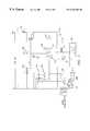
- FIG. 5is a schematic illustrating the electrical connections and layout of the components within the pager-based controller.
- FIG. 6is a schematic illustrating the electrical connections and layout of the components within a preferred embodiment of the pager-based controller.
- FIG. 1shows a simplified block diagram of the internal components of a pager-based controller 10 in accordance with the present invention.
- Controller 10includes a pair of pocket pagers 14 a , 14 b which receive paging signals from a pager network.
- Pagers 14 a , 14 bare registered with the pager network and are each allocated a different pager (telephone) number. Each time a remote operator or automated computer dials the respective pager number through the PSTN, the associated pager 14 a or 14 b receives the page signal via the PSTN and pager network.
- the associated pager 14 a or 14 bWhenever the page signal is received, the associated pager 14 a or 14 b outputs a control signal to an opto-isolator drive circuit 16 , which in turn changes a switching state of a power relay 20 .
- relay 20When pager 14 a receives a page signal, relay 20 is switched to an ON state.
- pager 14 breceives a page signal, relay 20 is switched to an OFF state.
- the switching of power relay 20is used to switch an external electrical device on or off.
- the external electrical devicemay be, for example, a remote computer system, building lighting, a security system, a capacitor bank, a remote electric generating station, an electric meter or a thermostat.
- pager-based controller 10may alternatively be employed to control other types of electrical or electronic equipment.
- a pair of pagers 14 a , 14 ba single pager could be alternatively utilized within each controller 10 . The use of two pagers ensures that the controller remains in operational sync. With the single pager approach, alternating pages would change the switching state of the relay. As such, it would then be necessary for the remote operator or computer to keep track of the current switching state of the relay.
- Controller 10is preferably embodied as a small portable unit deployable in the field, with a fiberglass housing 12 to environmentally protect the circuitry therein.
- Pocket pagers 14 a , 14 bmay be modified conventional pagers (e.g., Motorola Bravo, Bravo Plus or Advisor pagers) and can be maintained within their original housings 24 to simplify mounting within the controller 10 .
- electromagnetic shieldingmay be used along the inner surface of the pager housing 24 to reduce electromagnetic interference (EMI) susceptibility.
- the pocket pagerstypically operate in a one-way pager system, although two-way pagers can also be used.
- Pagers 14 a and 14 bare modified from their commercial design simply by having their batteries and vibrators removed.
- Conventional pagersinclude a vibrator which vibrates whenever a page is received to convey vibrational movement to the person wearing the pager. Vibrating action is typically selected by the user via a mode switch on the pager. When vibrating action is selected, the audio output of the pager is deactivated such that the user can effectively receive pages without an accompanying (disturbing) audible tone.
- AC line voltage(e.g., 115V, 60 Hz) is supplied to controller 10 and applied to an AC/DC converter 28 , which converts the line voltage to a low DC voltage.
- This DC voltageis used to power the electronics within controller 10 , including pagers 14 a and 14 b (which have their batteries removed).
- an alternative energy source known to one having ordinary skill in the artsuch as a DC battery or solar power, could be used to power the various components rather than the AC line voltage and converter 28 .
- pager 14 a or 14 bWhen a page signal is transmitted to controller 10 , pager 14 a or 14 b receives the page and responds by outputting the control voltage normally used to drive the respective vibrator.
- the control voltageis supplied to an opto-isolator drive circuit 16 on line 27 a or 27 b .
- Drive circuit 16includes two portions, 16 a and 16 b , each including respective opto-isolator electronics 17 a or 17 b .
- Drive circuit 16responds to the control voltage on line 27 a or 27 b by outputting a respective output voltage VRa or VRb at an appropriate level to power relay 20 , preferably a latching relay. When one of these voltages is applied to relay 20 , the switching state of the relay changes.
- the power relay 20includes a latching relay switch 22 that locks in one of two positions A or B corresponding to an energized or de-energized state of the external electronic device, until electrically reset by a new application of the voltage VRa or VRb from drive circuit 16 .
- the switch 22 inputis connected to the AC line voltage on line 33 .
- the switch outputconnects to either line 34 a or 34 b which may connect to a high voltage (several thousand volts) switch at the terminals of the external electrical device. As such, when power relay 20 changes switching state, the operational state of the external electrical device is correspondingly changed via the high voltage switch.
- the opto-isolators within drive circuit 16operate to isolate the pagers 14 from the relatively high voltage/current levels at the power relay 20 .
- the drive circuit 16thus prevents voltage spikes from reaching the pagers 14 during operation of the external electrical device.
- a fusemay also be provided on lines 33 and/or 34 a , 34 b to avoid damage to the relay 20 if current is excessively high.
- AC/DC converter 28supplies DC voltage to pagers 14 a , 14 b and drive circuit 16 .
- the energy requirement of each pageris 80 mA at 1.5 VDC.
- AC voltageis provided to the drive circuit 16 on the line 26 through a power-up, time delay relay (timer) 29 .
- Timer 29monitors the AC line voltage and functions to prevent the relay 20 from changing its switching state in the event of a loss or momentary drop of AC voltage as in a power failure. This is accomplished by temporarily removing AC control power to the output of the opto-isolator drive circuit.
- a test beep or vibrationis activated. This feature may not be capable of being programmed out of the pagers.
- Timer 29therefore prohibits the power relay 20 from operating in response to a test beep or vibration.
- the timer 29would be unnecessary for embodiments that do not operate with AC line voltage but which instead employ a DC power source.
- Each controller 10preferably includes a heater and fan (not shown) within the enclosure to maintain the pagers and other electronics within a proper operating temperature range.
- FIG. 2a simplified block diagram of the conventional pocket pager 14 modified for use as pager 14 a or 14 b within the pager-based controller 10 is illustrated.
- Pocket pager 14has the battery and vibrator removed and the battery contact points T 1 , T 2 coupled to the AC/DC converter 28 to receive the proper operating voltage for the electronics within the pager.
- a motor drive circuit 34is coupled to the opto-isolator drive circuit 16 via connection at terminal points T 3 , T 4 normally connected to the vibrator.
- a mode switch 35is set to the vibrator position such that when a page is received by receiver/control circuit 32 via antenna 15 , it responds by sending a command to motor drive circuit 34 rather than to the audio driver 36 .
- Motor drive circuit 34responds by outputting a voltage V 1 of approximately 1.5 volts for a short duration.
- Pager 14also includes LED driver 38 , LED display 39 and audio transducer 37 . These components are preferably not removed, since they can be used to verify reception of pages for testing purposes. It is noted that in alternative embodiments of the controller 10 , it is possible to tap into the LED driver 38 and/or audio driver 36 (rather than or in addition to the motor drive circuit 34 ) to derive control signals for controlling the power relay switching state.
- conventional pocket pagersare normally programmed by the pager company prior to delivery.
- a standard program used by the pager companyrequires the pager to give a reminder beep or vibration if the page is not acknowledged by pressing a button. The vibration is caused by a small motor with an unbalanced shaft which vibrates the pager. Since the pagers will be unattended, the typical pager programming needs to be modified to disable the reminder function.
- a remote control system 100which includes the pager-based controller 10 of the present invention.
- the system 100controls the operational states of external electrical devices 50 .
- System 100includes a remote telecommunication terminal 70 which is connected to the PSTN 110 by a conventional telephone line 108 .
- Terminal 70can be as simple as a single telephone 80 operated by a human operator, or as complex as a fully automated computer 90 which maintains, inter alia, a memory of the operational state of each external electrical device. In the latter case, computer 90 automatically dials the pager numbers of pagers 14 within associated controllers 10 to dynamically switch specific external electrical devices 50 into and out of operation based on the desired result.
- an electric generating station or capacitor bankmay be switched in and out of service based on electric power requirements within a certain geographical area.
- the callis relayed through the PSTN 110 to a paging messaging center 60 via a wireline or wireless communication link 105 .
- Messaging center 60is coupled to each of a number of paging base stations 40 by means of wireline or wireless communication links 120 .
- each pager registered in the systemcan receive pages only within specific geographical regions associated with a particular one or more pager base stations 40 .
- each controller 10when a call to a specific pager number is routed by the PSTN to messaging center 60 , the messaging center relays the call to the particular base station 40 associated with that pager. Each associated base station 40 then transmits the page signal.
- the pager within controller 10receives the specific page signal and switches the relay state accordingly. (It is noted that in some pager networks, each pager base station may transmit all pages to every pager registered with the system. The exemplary system of this invention can operate with this type of pager network as well).
- a security measuremay be incorporated to prevent persons other than the responsible operator or computer system at terminal 70 from dialing the pager numbers and thus changing the states of capacitor banks.
- a security/access codecan be allocated by the pager network service provider to each pager 14 . Therefore, in order to communicate with a pager 14 in the pager system 100 , the security/access code must be transmitted followed by the corresponding telephone number (or vice versa) for that particular pager 14 .
- FIGS. 4 and 5typical physical and electrical layouts of the several individual components of pager-based controller 10 are illustrated.
- the boxes labeled “TRIP CONTROL” and “CLOSE CONTROL”represent pagers 14 a and 14 b for receiving pager signals from a pager network.
- the “POWER SUPPLY” 28supplies 115 VAC power to components such as heater 150 , latching relay 20 and timing relay 29 .
- the 115 VAC poweris connected to the above components through isolation transformer 154 .
- Heater 150operates in response to the heater control switch 166 which is preferably set to close at 45° F. and open at 55° F.
- Power supply 28also supplies 12 VDC power to the fan 164 and the interface 16 .
- Interface 16provides a 1.5 VDC supply to each of pagers 14 a and 14 b and includes connections to receive the signals from the pagers which interface with latching relay 20 .
- the 12 VDC fan 164operates in response to the thermostat fan control switch 158 which is preferably set to open at 90° F. and close at 110° F.
- the coil in latching relay 20will be selectively energized to provide a corresponding output to an external electrical device.
- latching relay 20In the trip position, latching relay 20 will be energized thereby closing the normally open (NO) trip contact 21 and opening the normally closed (NC) close contact 23 , as long as the time delay switch 168 off the timing relay 29 is closed, and the external electrical component will trip.
- the coil in latching relay 20When the coil in latching relay 20 is de-energized, the contacts will return to their normal state, thereby closing the circuit of the external electrical component.
- Timing relay 29may be set within a range of approximately one minute to approximately ten minutes, and is preferably set for one minute to eliminate spurious changes in the circuit during power start-up.
- Terminal block 160is provided within the controller housing to connect the 115 VAC power feed to the controller, and to connect the latching relay contacts to the apparatus to be controlled.
- Switch 162is provided to facilitate manual control of the output from the controller. Switch 162 may be selectively switched between a trip and a close position to energize or de-energize latching relay 20 .
- the pager-based controllerincludes an additional control switch 163 .
- control switch 163is in series with the associated contacts and switch of timing relay 29 .
- the purpose of switch 163is to permit a user to switch between a local and remote control, while the user is at the remote location. That is, when switch 163 is in the “local” position, the user may locally operate switch 162 between a trip and close position. During normal operating conditions, switch 163 will be in the “remote” position such that the pager-based controller will receive and output signals corresponding to remote signals sent to the pagers.
- a pager-based remote control system and controllerparticularly useful for controlling switching states of electronic equipment.
- conventional pocket pagersare used to receive RF paging signals through a paging network, there are minimal costs in setting up and maintaining the remote control system of the present disclosure.
- customized transceiver circuitry and a radio networkare not necessary to operate the pager-based controller 10 of the present disclosure.
Landscapes
- Physics & Mathematics (AREA)
- Engineering & Computer Science (AREA)
- Computer Networks & Wireless Communication (AREA)
- General Physics & Mathematics (AREA)
- Electromagnetism (AREA)
- Mobile Radio Communication Systems (AREA)
- Selective Calling Equipment (AREA)
- Input Circuits Of Receivers And Coupling Of Receivers And Audio Equipment (AREA)
- Measuring Pulse, Heart Rate, Blood Pressure Or Blood Flow (AREA)
- Lock And Its Accessories (AREA)
Abstract
Description
This application claims the benefit of U.S. Provisional Application No. 60/036,275, filed Jan. 24, 1997, and incorporated by reference herein.
1. Field of the Invention
The present disclosure relates generally to remote control systems for remotely controlling electrical equipment. More particularly, this disclosure relates to a controller which receives pager signals from a pager network to control electrical/electronic equipment.
2. Description of the Related Art
Remote control systems which are capable of generating and transmitting control signals to remotely control electronic equipment are known in the prior art. Electric utility companies, for example, typically utilize a private remote control system with a private radio network to remotely control on/off switching of capacitor banks in accordance with daily electric power requirements. Such systems, however, are costly in that they require implementation and maintenance of the private radio network. In addition, their utility is generally limited to a narrow geographical region.
Hence, a need exists for a generally inexpensive remote control system which uses the public system telephone network (PSTN) to transmit control signals over a wide geographical region to remotely control electrical/electronic equipment.
The present invention relates to a remote control system in which RF pager signals transmitted by means of a wide area pager network, are received by a pager-based controller to control electrical or electronic equipment. A human operator or automated computer at a telecommunication station connected to the PSTN, initiates the transmission of RF pager signals via the pager network to the pager-based controller at the remote equipment site. In a preferred embodiment, the pager-based controller includes at least one conventional pocket pager which has been modified by having its vibrator or other indicator removed. Each time the pocket pager receives a page, it outputs a control voltage normally used to drive the vibrator. This control voltage is used to change the switching state of a relay within the controller to thereby control the on-off state of external electronics connected to the relay.
In an exemplary embodiment, two pagers are employed within the controller, each having a different pager (telecommunication) number. One pager is paged to set the relay to an ON state, while the other is paged to set the relay to an OFF state. The relay may be connected to the external electronics. As such, the external electronics can be switched into and out of operation merely by the remote operator or automated computer dialing the telecommunication number of the respective pager as allocated by the PSTN and pager network.
A pager-based controller is provided which includes at least one pager configured to receive a signal from a remote location, the at least one pager being further configured to provide an output to change an on-off state of an external electrical component; a heater unit and a fan unit to maintain a predetermined temperature range within the pager-based controller; a power supply for supplying a required AC voltage and DC voltage to electrical components within the pager-based controller; a latching relay electrically connected to the at least one pager; an interface unit electrically connected to the at least one pager and the latching relay, the interface unit configured to receive the output from the at least one pager and supply a corresponding signal to the latching relay; the latching relay including at least one normally-open contact and at least one normally-closed contact, for providing one of an open and a closed circuit to the external electrical component in response to an energization state of a coil within the latching relay; and a timing relay having a contact electrically connected in series with the output of the at least one pager to eliminate spurious signals from the at least one pager during a power-up operation.
A method of remotely controlling an electronic device is also provided which includes the steps of transmitting a first pager signal from a pager network to a pager-based controller having at least one pager therein; outputting a first control voltage from the at least one pager controller to change a switching state of a relay within the pager-based controller to thereby control an on-off state of an external electronic device which is electrically connected to the relay; and transmitting a second pager signal from the pager network to the pager-based controller at the remote site to cause a second control voltage to change the switching state of the relay within the controller to switch the on-off state of the external electronic device to a state which is opposite that which was caused by the first control voltage.
Advantageously, the use of conventional pocket pagers within the controller requires minimal set-up and maintenance costs and provides a reliable method of controlling the capacitor bank via the use of the pager network. Set-up costs are minimal since a customized private radio network for the transmission of control signals is not necessary.
For a better understanding of the invention, reference is made to the following description of exemplary embodiments thereof, and to the accompanying drawings, wherein:
FIG. 1 is a block diagram of a pager-based controller in accordance with the present invention;
FIG. 2 is a block diagram of a conventional pocket pager configured to be utilized within the pager-based capacitor bank controller of the present invention;
FIG. 3 is a block diagram of an illustrative remote control system including a pager network and multiple pager-based controllers of the present invention;
FIG. 4 is a block diagram of a typical layout of components within the pager-based controller;
FIG. 5 is a schematic illustrating the electrical connections and layout of the components within the pager-based controller; and
FIG. 6 is a schematic illustrating the electrical connections and layout of the components within a preferred embodiment of the pager-based controller.
FIG. 1 shows a simplified block diagram of the internal components of a pager-basedcontroller 10 in accordance with the present invention.Controller 10 includes a pair ofpocket pagers Pagers pager pager isolator drive circuit 16, which in turn changes a switching state of apower relay 20. Whenpager 14areceives a page signal,relay 20 is switched to an ON state. Whenpager 14breceives a page signal,relay 20 is switched to an OFF state.
In a preferred embodiment, the switching ofpower relay 20 is used to switch an external electrical device on or off. The external electrical device may be, for example, a remote computer system, building lighting, a security system, a capacitor bank, a remote electric generating station, an electric meter or a thermostat. However, it is to be understood that pager-basedcontroller 10 may alternatively be employed to control other types of electrical or electronic equipment. In addition, while it is preferable to employ a pair ofpagers controller 10. The use of two pagers ensures that the controller remains in operational sync. With the single pager approach, alternating pages would change the switching state of the relay. As such, it would then be necessary for the remote operator or computer to keep track of the current switching state of the relay.
AC line voltage (e.g., 115V, 60 Hz) is supplied tocontroller 10 and applied to an AC/DC converter 28, which converts the line voltage to a low DC voltage. This DC voltage is used to power the electronics withincontroller 10, including pagers14aand14b(which have their batteries removed). As an alternative, an alternative energy source known to one having ordinary skill in the art, such as a DC battery or solar power, could be used to power the various components rather than the AC line voltage andconverter 28.
When a page signal is transmitted tocontroller 10,pager isolator drive circuit 16 online Drive circuit 16 includes two portions,16aand16b, each including respective opto-isolator electronics circuit 16 responds to the control voltage online power relay 20, preferably a latching relay. When one of these voltages is applied to relay20, the switching state of the relay changes.
Thepower relay 20 includes a latchingrelay switch 22 that locks in one of two positions A or B corresponding to an energized or de-energized state of the external electronic device, until electrically reset by a new application of the voltage VRa or VRb fromdrive circuit 16. Theswitch 22 input is connected to the AC line voltage online 33. The switch output connects to eitherline power relay 20 changes switching state, the operational state of the external electrical device is correspondingly changed via the high voltage switch.
The opto-isolators withindrive circuit 16 operate to isolate thepagers 14 from the relatively high voltage/current levels at thepower relay 20. Thedrive circuit 16 thus prevents voltage spikes from reaching thepagers 14 during operation of the external electrical device. A fuse may also be provided onlines 33 and/or34a,34bto avoid damage to therelay 20 if current is excessively high.
AC/DC converter 28 supplies DC voltage topagers circuit 16. Typically, the energy requirement of each pager is 80 mA at 1.5 VDC. AC voltage is provided to thedrive circuit 16 on theline 26 through a power-up, time delay relay (timer)29.Timer 29 monitors the AC line voltage and functions to prevent therelay 20 from changing its switching state in the event of a loss or momentary drop of AC voltage as in a power failure. This is accomplished by temporarily removing AC control power to the output of the opto-isolator drive circuit. Additionally, each time a pager is turned on or powered up, a test beep or vibration is activated. This feature may not be capable of being programmed out of the pagers.Timer 29 therefore prohibits thepower relay 20 from operating in response to a test beep or vibration. Thetimer 29 would be unnecessary for embodiments that do not operate with AC line voltage but which instead employ a DC power source.
Eachcontroller 10 preferably includes a heater and fan (not shown) within the enclosure to maintain the pagers and other electronics within a proper operating temperature range.
With reference now to FIG. 2, a simplified block diagram of theconventional pocket pager 14 modified for use aspager controller 10 is illustrated.Pocket pager 14 has the battery and vibrator removed and the battery contact points T1, T2 coupled to the AC/DC converter 28 to receive the proper operating voltage for the electronics within the pager. Amotor drive circuit 34 is coupled to the opto-isolator drive circuit 16 via connection at terminal points T3, T4 normally connected to the vibrator. Amode switch 35 is set to the vibrator position such that when a page is received by receiver/control circuit 32 viaantenna 15, it responds by sending a command tomotor drive circuit 34 rather than to theaudio driver 36.Motor drive circuit 34 responds by outputting a voltage V1 of approximately 1.5 volts for a short duration.Pager 14 also includesLED driver 38,LED display 39 andaudio transducer 37. These components are preferably not removed, since they can be used to verify reception of pages for testing purposes. It is noted that in alternative embodiments of thecontroller 10, it is possible to tap into theLED driver 38 and/or audio driver36 (rather than or in addition to the motor drive circuit34) to derive control signals for controlling the power relay switching state.
Furthermore, conventional pocket pagers are normally programmed by the pager company prior to delivery. A standard program used by the pager company requires the pager to give a reminder beep or vibration if the page is not acknowledged by pressing a button. The vibration is caused by a small motor with an unbalanced shaft which vibrates the pager. Since the pagers will be unattended, the typical pager programming needs to be modified to disable the reminder function.
Referring now to FIG. 3, aremote control system 100 is illustrated which includes the pager-basedcontroller 10 of the present invention. Thesystem 100 controls the operational states of externalelectrical devices 50.System 100 includes aremote telecommunication terminal 70 which is connected to thePSTN 110 by aconventional telephone line 108.Terminal 70 can be as simple as asingle telephone 80 operated by a human operator, or as complex as a fully automatedcomputer 90 which maintains, inter alia, a memory of the operational state of each external electrical device. In the latter case,computer 90 automatically dials the pager numbers ofpagers 14 within associatedcontrollers 10 to dynamically switch specific externalelectrical devices 50 into and out of operation based on the desired result. For example, an electric generating station or capacitor bank may be switched in and out of service based on electric power requirements within a certain geographical area. When a page is initiated atterminal 70, the call is relayed through thePSTN 110 to apaging messaging center 60 via a wireline orwireless communication link 105.Messaging center 60 is coupled to each of a number ofpaging base stations 40 by means of wireline or wireless communication links120. Typically, with one-way pager networks, each pager registered in the system can receive pages only within specific geographical regions associated with a particular one or morepager base stations 40. As such, when a call to a specific pager number is routed by the PSTN tomessaging center 60, the messaging center relays the call to theparticular base station 40 associated with that pager. Each associatedbase station 40 then transmits the page signal. In the exemplary system described herein, since the external electrical devices controlled by eachcontroller 10 are typically at fixed locations, only asingle base station 40 need transmit the specific page signal to change the switching state of the corresponding externalelectrical device 50. The pager withincontroller 10 receives the specific page signal and switches the relay state accordingly. (It is noted that in some pager networks, each pager base station may transmit all pages to every pager registered with the system. The exemplary system of this invention can operate with this type of pager network as well).
A security measure may be incorporated to prevent persons other than the responsible operator or computer system at terminal70 from dialing the pager numbers and thus changing the states of capacitor banks. For example, a security/access code can be allocated by the pager network service provider to eachpager 14. Therefore, in order to communicate with apager 14 in thepager system 100, the security/access code must be transmitted followed by the corresponding telephone number (or vice versa) for thatparticular pager 14.
Referring now to FIGS. 4 and 5, typical physical and electrical layouts of the several individual components of pager-basedcontroller 10 are illustrated. The boxes labeled “TRIP CONTROL” and “CLOSE CONTROL” representpagers supplies 115 VAC power to components such asheater 150, latchingrelay 20 andtiming relay 29. The 115 VAC power is connected to the above components throughisolation transformer 154.Heater 150 operates in response to theheater control switch 166 which is preferably set to close at 45° F. and open at 55°F. Power supply 28 also supplies 12 VDC power to thefan 164 and theinterface 16.Interface 16 provides a 1.5 VDC supply to each ofpagers relay 20. The 12VDC fan 164 operates in response to the thermostatfan control switch 158 which is preferably set to open at 90° F. and close at 110° F.
During operation, in response to a signal frompager relay 20 will be selectively energized to provide a corresponding output to an external electrical device. In the trip position, latchingrelay 20 will be energized thereby closing the normally open (NO)trip contact 21 and opening the normally closed (NC)close contact 23, as long as thetime delay switch 168 off thetiming relay 29 is closed, and the external electrical component will trip. When the coil in latchingrelay 20 is de-energized, the contacts will return to their normal state, thereby closing the circuit of the external electrical component. Timingrelay 29 may be set within a range of approximately one minute to approximately ten minutes, and is preferably set for one minute to eliminate spurious changes in the circuit during power start-up.Terminal block 160 is provided within the controller housing to connect the 115 VAC power feed to the controller, and to connect the latching relay contacts to the apparatus to be controlled.Switch 162 is provided to facilitate manual control of the output from the controller.Switch 162 may be selectively switched between a trip and a close position to energize or de-energize latchingrelay 20.
In a preferred embodiment, the pager-based controller includes anadditional control switch 163. As illustrated in the electrical schematic of FIG. 6,control switch 163 is in series with the associated contacts and switch oftiming relay 29. The purpose ofswitch 163 is to permit a user to switch between a local and remote control, while the user is at the remote location. That is, whenswitch 163 is in the “local” position, the user may locally operateswitch 162 between a trip and close position. During normal operating conditions, switch163 will be in the “remote” position such that the pager-based controller will receive and output signals corresponding to remote signals sent to the pagers.
Thus disclosed is a pager-based remote control system and controller particularly useful for controlling switching states of electronic equipment. Advantageously, since conventional pocket pagers are used to receive RF paging signals through a paging network, there are minimal costs in setting up and maintaining the remote control system of the present disclosure. Further, customized transceiver circuitry and a radio network are not necessary to operate the pager-basedcontroller 10 of the present disclosure.
It is to be understood that the embodiments described herein are merely exemplary and that one skilled in the art can make many modifications and variations to the disclosed embodiments without departing from the spirit or scope of the invention. For example, the present invention is not to be understood to be limited to employment in a pager system, but rather may be employed into numerous wireless communication systems, such as a Personal Communication Network (PCN) or into communication systems utilizing Personal and/or Terminal Mobility managers. According, all such modifications and variations are intended to be included within the scope and spirit of the present invention.
Claims (19)
1. A system for controlling the on-off state of a remote electrical device comprising:
a pager-based controller; and
a terminal for transmitting a signal to the pager based controller;
wherein the pager-based controller comprises a housing; at least one pager positioned within the housing and configured to receive a signal from the terminal, said at least one pager being further configured to provide an alarm output to change an on-off state of an external electrical device; and a time delay relay having a contact electrically connected in series with the alarm output of the at least one pager, said time delay relay operable to prevent the pager from changing the on-off state of the external electrical device for a predetermined time period during a power-up operation of the pager-based controller.
2. The system for controlling the on-off state of a remote electrical device as recited inclaim 1 , wherein the pager-based controller further comprises an interface unit electrically connected to the at least one pager, the interface unit configured to receive the output from the at least one pager and supply a corresponding signal the external electrical device.
3. The system for controlling the on-off state of a remote electrical device as recited inclaim 1 , wherein the terminal is a telephone.
4. The system for controlling the on-off state of a remote electrical device as recited inclaim 1 , wherein the terminal is a computer.
5. The pager-based controller as recited inclaim 1 wherein the electrical device is a capacitor bank.
6. The system for controlling the on-off state of a remote electrical device as recited inclaim 1 , wherein the at least one pager is removably positioned within the housing.
7. A pager-based controller which comprises:
a housing;
at least one pager positioned within the housing and configured to receive a signal from a remote location, said at least one pager being further configured to provide an alarm output to change an on-off state of an external electrical device; and
a time delay relay having a contact electrically connected in series with the alarm output of the at least one pager, said time delay relay operable to prevent the pager from changing the on-off state of the external electrical device for a predetermined time period during a power-up operation pager-based controller.
8. The pager-based controller as recited inclaim 7 , further comprising an interface unit electrically connected to the at least one pager, the interface unit configured to receive the output from the at least one pager and supply a corresponding signal to the external electrical device.
9. The pager-based controller as recited inclaim 8 , wherein the interface unit is further configured to electrically isolate the at least one pager from at least one of a high voltage and a high current.
10. The pager-based controller as recited inclaim 8 , wherein the interface unit is an opto-isolator drive circuit.
11. The pager-based controller as recited inclaim 7 , further comprising a power supply for supplying a required AC voltage and DC voltage to electrical components within the pager-based controller.
12. The pager-based controller as recited inclaim 7 , further comprising a latching relay electrically connected between the interface unit and the external electrical device.
13. The pager-based controller as recited inclaim 12 , wherein the latching relay includes at least one normally-open contact and at least one normally-closed contact for providing one of an open and a closed circuit to the external electrical device in response to an energization state of a coil within the latching relay.
14. The pager-based controller as recited inclaim 7 , wherein the time delay relay is set for a delay within a range of about one minute to about ten minutes.
15. The pager-based controller as recited inclaim 7 , further comprising a switch capable of switching between local and remote control of the controller.
16. The pager-based controller as recited inclaim 7 , wherein the output of the at least one pager is a voltage from a motor drive circuit within the at least one pager.
17. The pager-based controller as recited inclaim 7 , further comprising a heater unit and a fan unit to maintain a predetermined temperature range within the pager-based controller housing.
18. The pager-based controller as recited inclaim 17 , wherein the predetermined temperature range is between 45 degrees fahrenheit and 110 degrees fahrenheit.
19. The pager-based controller as recited inclaim 7 , wherein the at least one pager is removably positioned within the housing.
Priority Applications (2)
| Application Number | Priority Date | Filing Date | Title |
|---|---|---|---|
| US09/010,278US6374101B1 (en) | 1997-01-24 | 1998-01-21 | Pager-based controller |
| US09/667,351US6829476B1 (en) | 1997-01-24 | 2000-09-22 | Pager-based gas valve controller |
Applications Claiming Priority (2)
| Application Number | Priority Date | Filing Date | Title |
|---|---|---|---|
| US3627597P | 1997-01-24 | 1997-01-24 | |
| US09/010,278US6374101B1 (en) | 1997-01-24 | 1998-01-21 | Pager-based controller |
Related Child Applications (1)
| Application Number | Title | Priority Date | Filing Date |
|---|---|---|---|
| US09/667,351Continuation-In-PartUS6829476B1 (en) | 1997-01-24 | 2000-09-22 | Pager-based gas valve controller |
Publications (1)
| Publication Number | Publication Date |
|---|---|
| US6374101B1true US6374101B1 (en) | 2002-04-16 |
Family
ID=21887674
Family Applications (1)
| Application Number | Title | Priority Date | Filing Date |
|---|---|---|---|
| US09/010,278Expired - Fee RelatedUS6374101B1 (en) | 1997-01-24 | 1998-01-21 | Pager-based controller |
Country Status (6)
| Country | Link |
|---|---|
| US (1) | US6374101B1 (en) |
| EP (1) | EP0954834B1 (en) |
| AT (1) | ATE208072T1 (en) |
| CA (1) | CA2278550A1 (en) |
| DE (1) | DE69802258T2 (en) |
| WO (1) | WO1998033153A1 (en) |
Cited By (35)
| Publication number | Priority date | Publication date | Assignee | Title |
|---|---|---|---|---|
| US20020116541A1 (en)* | 2000-12-19 | 2002-08-22 | Microsoft Corporation | System and method for optimizing user notifications for small computer devices |
| US20030087615A1 (en)* | 2001-09-25 | 2003-05-08 | Randall Bruce E. | Utility meter power arrangements and methods |
| US6829476B1 (en)* | 1997-01-24 | 2004-12-07 | Lawrence J. Gelbein | Pager-based gas valve controller |
| US20050174256A1 (en)* | 2000-09-27 | 2005-08-11 | Berg Eric P. | Remote disconnect systems for utility meters |
| US20050215237A1 (en)* | 2004-03-24 | 2005-09-29 | Carrier Corporation | Method of setting the output power of a pager to aid in the installation of a wireless system |
| US7009493B2 (en)* | 2001-06-22 | 2006-03-07 | Matsushita Electric Works, Ltd. | Electronic device with paging for energy curtailment and code generation for manual verification of curtailment |
| US20090280769A1 (en)* | 2005-02-09 | 2009-11-12 | Sony Corporation | System and method for standby mode in directional signal receiver |
| US20100145544A1 (en)* | 2007-08-28 | 2010-06-10 | Forbes Jr Joseph W | System and method for selective disconnection of electrical service to end customers |
| US20100161148A1 (en)* | 2007-08-28 | 2010-06-24 | Forbes Jr Joseph W | Method and apparatus for actively managing consumption of electric power supplied by an electric utility |
| US7847706B1 (en)* | 2004-06-23 | 2010-12-07 | Wireless Telematics Llc | Wireless electrical apparatus controller device and method of use |
| US20110022239A1 (en)* | 2007-08-28 | 2011-01-27 | Forbes Jr Joseph W | Method and apparatus for effecting controlled restart of electrical servcie with a utility service area |
| US20110172841A1 (en)* | 2007-08-28 | 2011-07-14 | Forbes Jr Joseph W | Method and Apparatus for Actively Managing Consumption of Electric Power Supplied by One or More Electric Utilities |
| US20110172837A1 (en)* | 2007-08-28 | 2011-07-14 | Forbes Jr Joseph W | System and method for estimating and providing dispatchable operating reserve energy capacity through use of active load management |
| US8396606B2 (en) | 2007-08-28 | 2013-03-12 | Consert Inc. | System and method for estimating and providing dispatchable operating reserve energy capacity through use of active load management |
| US8421588B1 (en) | 2004-06-23 | 2013-04-16 | Wireless Telematics Llc | Combination wireless electrical apparatus controller and energy monitoring device and method of use |
| US8805552B2 (en) | 2007-08-28 | 2014-08-12 | Causam Energy, Inc. | Method and apparatus for actively managing consumption of electric power over an electric power grid |
| US8806239B2 (en) | 2007-08-28 | 2014-08-12 | Causam Energy, Inc. | System, method, and apparatus for actively managing consumption of electric power supplied by one or more electric power grid operators |
| US8849715B2 (en) | 2012-10-24 | 2014-09-30 | Causam Energy, Inc. | System, method, and apparatus for settlement for participation in an electric power grid |
| US8855279B2 (en) | 2007-08-28 | 2014-10-07 | Consert Inc. | Apparatus and method for controlling communications to and from utility service points |
| US8890505B2 (en) | 2007-08-28 | 2014-11-18 | Causam Energy, Inc. | System and method for estimating and providing dispatchable operating reserve energy capacity through use of active load management |
| US9130402B2 (en) | 2007-08-28 | 2015-09-08 | Causam Energy, Inc. | System and method for generating and providing dispatchable operating reserve energy capacity through use of active load management |
| US9177323B2 (en) | 2007-08-28 | 2015-11-03 | Causam Energy, Inc. | Systems and methods for determining and utilizing customer energy profiles for load control for individual structures, devices, and aggregation of same |
| US9207698B2 (en) | 2012-06-20 | 2015-12-08 | Causam Energy, Inc. | Method and apparatus for actively managing electric power over an electric power grid |
| US9418543B1 (en) | 2004-06-23 | 2016-08-16 | Wireless Telematics Llc | Wireless electrical apparatus controller and method of use |
| US9513648B2 (en) | 2012-07-31 | 2016-12-06 | Causam Energy, Inc. | System, method, and apparatus for electric power grid and network management of grid elements |
| US9563215B2 (en) | 2012-07-14 | 2017-02-07 | Causam Energy, Inc. | Method and apparatus for actively managing electric power supply for an electric power grid |
| US10049565B1 (en) | 2004-06-23 | 2018-08-14 | Wireless Telematics Llc | Wireless electrical apparatus controller and method of use |
| US10295969B2 (en) | 2007-08-28 | 2019-05-21 | Causam Energy, Inc. | System and method for generating and providing dispatchable operating reserve energy capacity through use of active load management |
| US10310534B2 (en) | 2012-07-31 | 2019-06-04 | Causam Energy, Inc. | System, method, and data packets for messaging for electric power grid elements over a secure internet protocol network |
| US10547178B2 (en) | 2012-06-20 | 2020-01-28 | Causam Energy, Inc. | System and methods for actively managing electric power over an electric power grid |
| US10768653B2 (en) | 2012-06-20 | 2020-09-08 | Causam Holdings, LLC | System and methods for actively managing electric power over an electric power grid and providing revenue grade data usable for settlement |
| US10861112B2 (en) | 2012-07-31 | 2020-12-08 | Causam Energy, Inc. | Systems and methods for advanced energy settlements, network-based messaging, and applications supporting the same on a blockchain platform |
| US11004160B2 (en) | 2015-09-23 | 2021-05-11 | Causam Enterprises, Inc. | Systems and methods for advanced energy network |
| WO2022132925A1 (en)* | 2020-12-18 | 2022-06-23 | Gba Systems Integrators, Llc | Remote communications system and method |
| US12438368B2 (en) | 2007-08-28 | 2025-10-07 | Causam Enterprises, Inc. | System and method for estimating and providing dispatchable operating reserve energy capacity through use of active load management |
Families Citing this family (2)
| Publication number | Priority date | Publication date | Assignee | Title |
|---|---|---|---|---|
| CN101499378B (en)* | 2008-01-28 | 2011-01-05 | 陈耀华 | Low-power wireless remote control emitter |
| WO2024188542A1 (en)* | 2023-03-14 | 2024-09-19 | British Telecommunications Public Limited Company | A system in a telecommunications network and a method of retrofitting the same |
Citations (50)
| Publication number | Priority date | Publication date | Assignee | Title |
|---|---|---|---|---|
| US3114243A (en) | 1959-07-02 | 1963-12-17 | Willis R Winters | Automatic system of agricultural irrigation |
| US3372899A (en) | 1965-09-15 | 1968-03-12 | Robert Trent Jones Inc | Radio actuated and manually operable pilot valve controls |
| US3614326A (en) | 1969-07-07 | 1971-10-19 | Int Automated Electronics Corp | Telephone actuated switch |
| US3653595A (en) | 1970-12-07 | 1972-04-04 | Julius Edward Greengard Jr | Automatic turf watering systems |
| US3726477A (en) | 1971-06-02 | 1973-04-10 | J Shapiro | Automated irrigation system |
| US3783193A (en) | 1971-01-28 | 1974-01-01 | Pantek Corp | Apparatus for activating a remotely located device in response to the ringing of a called telephone subscriber station |
| US3859462A (en)* | 1973-08-15 | 1975-01-07 | Itt | Arrangement to control a function at a remote location |
| US4146049A (en) | 1977-07-28 | 1979-03-27 | Ag-Rain Incorporated | Traveling sprinkler radio-controlled mechanism and warning device |
| US4185650A (en) | 1977-06-20 | 1980-01-29 | Neves William T | Method and apparatus for trouble-shooting and irrigation system |
| US4206444A (en) | 1979-01-02 | 1980-06-03 | Honeywell Information Systems Inc. | Remote power controller utilizing communication lines |
| US4208630A (en) | 1978-10-19 | 1980-06-17 | Altran Electronics, Inc. | Narrow band paging or control radio system |
| US4209131A (en) | 1978-05-12 | 1980-06-24 | Motorola, Inc. | Computer-controlled irrigation system |
| US4266097A (en) | 1979-05-14 | 1981-05-05 | Bell Telephone Laboratories, Incorporated | Device control system |
| US4273961A (en) | 1979-11-14 | 1981-06-16 | Gte Laboratories Incorporated | Apparatus for communicating with processing apparatus over a telephone network |
| US4322842A (en)* | 1979-10-23 | 1982-03-30 | Altran Electronics | Broadcast system for distribution automation and remote metering |
| US4396149A (en) | 1980-12-30 | 1983-08-02 | Energy Management Corporation | Irrigation control system |
| US4473821A (en) | 1982-02-12 | 1984-09-25 | Ensco Inc. | Personal acoustic alarm system |
| US4598286A (en) | 1979-10-30 | 1986-07-01 | General Electric Company | Method and apparatus for controlling distributed electrical loads |
| US4626984A (en) | 1984-08-29 | 1986-12-02 | Valmont Industries, Inc. | Remote computer control for irrigation systems |
| US4628306A (en) | 1983-09-06 | 1986-12-09 | South Coast Research, Inc. | Remote control system for automated equipment |
| US4691341A (en) | 1985-03-18 | 1987-09-01 | General Electric Company | Method of transferring digital information and street lighting control system |
| US4724334A (en)* | 1987-03-19 | 1988-02-09 | Bernard Melek | Money-operated unit control system |
| US4806906A (en) | 1986-01-29 | 1989-02-21 | Nec Corporation | Data terminal |
| US4893351A (en) | 1987-09-02 | 1990-01-09 | Motorola, Inc. | Communication receiver having a remote alert device |
| US4935736A (en) | 1988-01-20 | 1990-06-19 | Merit Electronic Design Co., Ltd. | r. f. Remote controller for electrical loads having resistive or complex impedances |
| US4962522A (en)* | 1987-12-04 | 1990-10-09 | Marian Michael B | Electronic controller for sprinkler systems |
| US4996703A (en) | 1986-04-21 | 1991-02-26 | Gray William F | Remote supervisory monitoring and control apparatus connected to monitored equipment |
| US5012233A (en) | 1989-09-07 | 1991-04-30 | At&T Bell Laboratories | Communication system comprising a remotely activated switch |
| US5043721A (en) | 1989-12-18 | 1991-08-27 | Hewlett-Packard Company | Paging accessory for portable information/computing devices |
| US5061921A (en) | 1987-09-19 | 1991-10-29 | White Way Sign Company | Remote-controlled message sign |
| US5070329A (en) | 1989-12-04 | 1991-12-03 | Motorola, Inc. | On-site communication system with rf shielding having pager identification capability |
| US5148158A (en)* | 1988-03-24 | 1992-09-15 | Teledyne Industries, Inc. | Emergency lighting unit having remote test capability |
| US5153582A (en) | 1988-07-01 | 1992-10-06 | Motorola, Inc. | Method of and apparatus for acknowledging and answering a paging signal |
| US5175758A (en) | 1989-09-15 | 1992-12-29 | Nokia Mobile Phones Ltd. | Cellular telephone system integrated with paging network |
| US5208855A (en) | 1991-09-20 | 1993-05-04 | Marian Michael B | Method and apparatus for irrigation control using evapotranspiration |
| US5281962A (en) | 1992-05-08 | 1994-01-25 | Motorola, Inc. | Method and apparatus for automatic generation and notification of tag information corresponding to a received message |
| US5291193A (en) | 1988-01-21 | 1994-03-01 | Matsushita Electric Works, Ltd. | Identification registration for a wireless transmission-reception control system |
| US5337044A (en)* | 1991-10-08 | 1994-08-09 | Nomadic Systems, Inc. | System for remote computer control using message broadcasting system |
| US5359318A (en) | 1991-10-29 | 1994-10-25 | Nec Corporation | Hand-held electronic apparatus using two batteries sequentially supplying current to inductive element |
| US5392452A (en) | 1992-11-27 | 1995-02-21 | Motorola, Inc. | Selective call signaling system with combined wide area paging and high data rate transmissions via radio telephone transceivers |
| US5394560A (en) | 1992-09-30 | 1995-02-28 | Motorola, Inc. | Nationwide satellite message delivery system |
| US5455572A (en) | 1992-10-19 | 1995-10-03 | Motorola, Inc. | Selective call receiver with computer interface message notification |
| US5469133A (en) | 1993-11-29 | 1995-11-21 | Hensler; Scott E. | Telephone pager alarm enhancement and method therefor |
| EP0716553A2 (en) | 1994-12-05 | 1996-06-12 | Motorola, Inc. | Pager for wireless control and method therefor |
| US5661468A (en)* | 1994-12-15 | 1997-08-26 | Marcoux; Paul Alfred | Radio paging electrical load control system and device |
| US5693952A (en)* | 1995-12-18 | 1997-12-02 | Sulzer Intermedics Inc. | Optically controlled high-voltage switch for an implantable defibrillator |
| US5790036A (en)* | 1992-07-22 | 1998-08-04 | Health Sense International, Inc. | Sensor material for use in detection of electrically conductive fluids |
| US5872505A (en)* | 1997-03-06 | 1999-02-16 | Sony Corporation | Medication alert pager and paging system |
| US5881364A (en)* | 1995-04-11 | 1999-03-09 | Nec Corporation | Radio pager having correcting circuit responsive to temperature variation |
| US5986574A (en) | 1997-10-16 | 1999-11-16 | Peco Energy Company | System and method for communication between remote locations |
- 1998
- 1998-01-21USUS09/010,278patent/US6374101B1/ennot_activeExpired - Fee Related
- 1998-01-21CACA002278550Apatent/CA2278550A1/ennot_activeAbandoned
- 1998-01-21DEDE69802258Tpatent/DE69802258T2/ennot_activeExpired - Fee Related
- 1998-01-21EPEP98902652Apatent/EP0954834B1/ennot_activeExpired - Lifetime
- 1998-01-21ATAT98902652Tpatent/ATE208072T1/ennot_activeIP Right Cessation
- 1998-01-21WOPCT/US1998/001096patent/WO1998033153A1/enactiveIP Right Grant
Patent Citations (51)
| Publication number | Priority date | Publication date | Assignee | Title |
|---|---|---|---|---|
| US3114243A (en) | 1959-07-02 | 1963-12-17 | Willis R Winters | Automatic system of agricultural irrigation |
| US3372899A (en) | 1965-09-15 | 1968-03-12 | Robert Trent Jones Inc | Radio actuated and manually operable pilot valve controls |
| US3614326A (en) | 1969-07-07 | 1971-10-19 | Int Automated Electronics Corp | Telephone actuated switch |
| US3653595A (en) | 1970-12-07 | 1972-04-04 | Julius Edward Greengard Jr | Automatic turf watering systems |
| US3783193A (en) | 1971-01-28 | 1974-01-01 | Pantek Corp | Apparatus for activating a remotely located device in response to the ringing of a called telephone subscriber station |
| US3726477A (en) | 1971-06-02 | 1973-04-10 | J Shapiro | Automated irrigation system |
| US3859462A (en)* | 1973-08-15 | 1975-01-07 | Itt | Arrangement to control a function at a remote location |
| US4185650A (en) | 1977-06-20 | 1980-01-29 | Neves William T | Method and apparatus for trouble-shooting and irrigation system |
| US4146049A (en) | 1977-07-28 | 1979-03-27 | Ag-Rain Incorporated | Traveling sprinkler radio-controlled mechanism and warning device |
| US4209131A (en) | 1978-05-12 | 1980-06-24 | Motorola, Inc. | Computer-controlled irrigation system |
| US4208630A (en) | 1978-10-19 | 1980-06-17 | Altran Electronics, Inc. | Narrow band paging or control radio system |
| US4206444A (en) | 1979-01-02 | 1980-06-03 | Honeywell Information Systems Inc. | Remote power controller utilizing communication lines |
| US4266097A (en) | 1979-05-14 | 1981-05-05 | Bell Telephone Laboratories, Incorporated | Device control system |
| US4322842A (en)* | 1979-10-23 | 1982-03-30 | Altran Electronics | Broadcast system for distribution automation and remote metering |
| US4598286A (en) | 1979-10-30 | 1986-07-01 | General Electric Company | Method and apparatus for controlling distributed electrical loads |
| US4273961A (en) | 1979-11-14 | 1981-06-16 | Gte Laboratories Incorporated | Apparatus for communicating with processing apparatus over a telephone network |
| US4396149A (en) | 1980-12-30 | 1983-08-02 | Energy Management Corporation | Irrigation control system |
| US4473821A (en) | 1982-02-12 | 1984-09-25 | Ensco Inc. | Personal acoustic alarm system |
| US4628306A (en) | 1983-09-06 | 1986-12-09 | South Coast Research, Inc. | Remote control system for automated equipment |
| US4626984A (en) | 1984-08-29 | 1986-12-02 | Valmont Industries, Inc. | Remote computer control for irrigation systems |
| US4691341A (en) | 1985-03-18 | 1987-09-01 | General Electric Company | Method of transferring digital information and street lighting control system |
| US4806906A (en) | 1986-01-29 | 1989-02-21 | Nec Corporation | Data terminal |
| US4996703A (en) | 1986-04-21 | 1991-02-26 | Gray William F | Remote supervisory monitoring and control apparatus connected to monitored equipment |
| US4724334A (en)* | 1987-03-19 | 1988-02-09 | Bernard Melek | Money-operated unit control system |
| US4893351A (en) | 1987-09-02 | 1990-01-09 | Motorola, Inc. | Communication receiver having a remote alert device |
| US5061921A (en) | 1987-09-19 | 1991-10-29 | White Way Sign Company | Remote-controlled message sign |
| US4962522A (en)* | 1987-12-04 | 1990-10-09 | Marian Michael B | Electronic controller for sprinkler systems |
| US4935736A (en) | 1988-01-20 | 1990-06-19 | Merit Electronic Design Co., Ltd. | r. f. Remote controller for electrical loads having resistive or complex impedances |
| US5291193A (en) | 1988-01-21 | 1994-03-01 | Matsushita Electric Works, Ltd. | Identification registration for a wireless transmission-reception control system |
| US5148158A (en)* | 1988-03-24 | 1992-09-15 | Teledyne Industries, Inc. | Emergency lighting unit having remote test capability |
| US5153582A (en) | 1988-07-01 | 1992-10-06 | Motorola, Inc. | Method of and apparatus for acknowledging and answering a paging signal |
| US5012233A (en) | 1989-09-07 | 1991-04-30 | At&T Bell Laboratories | Communication system comprising a remotely activated switch |
| US5175758A (en) | 1989-09-15 | 1992-12-29 | Nokia Mobile Phones Ltd. | Cellular telephone system integrated with paging network |
| US5070329A (en) | 1989-12-04 | 1991-12-03 | Motorola, Inc. | On-site communication system with rf shielding having pager identification capability |
| US5043721A (en) | 1989-12-18 | 1991-08-27 | Hewlett-Packard Company | Paging accessory for portable information/computing devices |
| US5208855A (en) | 1991-09-20 | 1993-05-04 | Marian Michael B | Method and apparatus for irrigation control using evapotranspiration |
| US5337044A (en)* | 1991-10-08 | 1994-08-09 | Nomadic Systems, Inc. | System for remote computer control using message broadcasting system |
| US5359318A (en) | 1991-10-29 | 1994-10-25 | Nec Corporation | Hand-held electronic apparatus using two batteries sequentially supplying current to inductive element |
| US5281962A (en) | 1992-05-08 | 1994-01-25 | Motorola, Inc. | Method and apparatus for automatic generation and notification of tag information corresponding to a received message |
| US5790036A (en)* | 1992-07-22 | 1998-08-04 | Health Sense International, Inc. | Sensor material for use in detection of electrically conductive fluids |
| US5394560A (en) | 1992-09-30 | 1995-02-28 | Motorola, Inc. | Nationwide satellite message delivery system |
| US5455572A (en) | 1992-10-19 | 1995-10-03 | Motorola, Inc. | Selective call receiver with computer interface message notification |
| US5392452A (en) | 1992-11-27 | 1995-02-21 | Motorola, Inc. | Selective call signaling system with combined wide area paging and high data rate transmissions via radio telephone transceivers |
| US5469133A (en) | 1993-11-29 | 1995-11-21 | Hensler; Scott E. | Telephone pager alarm enhancement and method therefor |
| EP0716553A2 (en) | 1994-12-05 | 1996-06-12 | Motorola, Inc. | Pager for wireless control and method therefor |
| US5608655A (en) | 1994-12-05 | 1997-03-04 | Motorola, Inc. | Pager for wireless control and method therefor |
| US5661468A (en)* | 1994-12-15 | 1997-08-26 | Marcoux; Paul Alfred | Radio paging electrical load control system and device |
| US5881364A (en)* | 1995-04-11 | 1999-03-09 | Nec Corporation | Radio pager having correcting circuit responsive to temperature variation |
| US5693952A (en)* | 1995-12-18 | 1997-12-02 | Sulzer Intermedics Inc. | Optically controlled high-voltage switch for an implantable defibrillator |
| US5872505A (en)* | 1997-03-06 | 1999-02-16 | Sony Corporation | Medication alert pager and paging system |
| US5986574A (en) | 1997-10-16 | 1999-11-16 | Peco Energy Company | System and method for communication between remote locations |
Non-Patent Citations (3)
| Title |
|---|
| Page Tap ISD Catalogue. |
| Page Tap Model #PT8-OC Catalogue, Apr. 9, 1996. |
| Page Tap TT4 Remote Control Switch Catalogue, Apr. 9, 1996. |
Cited By (133)
| Publication number | Priority date | Publication date | Assignee | Title |
|---|---|---|---|---|
| US6829476B1 (en)* | 1997-01-24 | 2004-12-07 | Lawrence J. Gelbein | Pager-based gas valve controller |
| US20050174256A1 (en)* | 2000-09-27 | 2005-08-11 | Berg Eric P. | Remote disconnect systems for utility meters |
| US7458080B2 (en)* | 2000-12-19 | 2008-11-25 | Microsoft Corporation | System and method for optimizing user notifications for small computer devices |
| US8839273B2 (en) | 2000-12-19 | 2014-09-16 | Microsoft Corporation | System and method for optimizing user notifications for small computer devices |
| US9891963B2 (en) | 2000-12-19 | 2018-02-13 | Microsoft Technology Licensing, Llc | System and method for optimizing user notifications for small computer devices |
| US8352961B2 (en) | 2000-12-19 | 2013-01-08 | Microsoft Corporation | System and method for optimizing under notifications for small computer devices |
| US20020116541A1 (en)* | 2000-12-19 | 2002-08-22 | Microsoft Corporation | System and method for optimizing user notifications for small computer devices |
| US20090125917A1 (en)* | 2000-12-19 | 2009-05-14 | Microsoft Corporation | System and method for optimizing under notifications for small computer devices |
| US7009493B2 (en)* | 2001-06-22 | 2006-03-07 | Matsushita Electric Works, Ltd. | Electronic device with paging for energy curtailment and code generation for manual verification of curtailment |
| US6995685B2 (en)* | 2001-09-25 | 2006-02-07 | Landis+Gyr, Inc. | Utility meter power arrangements and methods |
| US10333564B2 (en) | 2001-09-25 | 2019-06-25 | Landis+Gyr Llc | Utility meter power arrangements |
| US20030087615A1 (en)* | 2001-09-25 | 2003-05-08 | Randall Bruce E. | Utility meter power arrangements and methods |
| US7167079B2 (en)* | 2004-03-24 | 2007-01-23 | Carrier Corporation | Method of setting the output power of a pager to aid in the installation of a wireless system |
| WO2005104051A3 (en)* | 2004-03-24 | 2006-09-08 | Carrier Corp | Method of setting the output power of a pager to aid in the installation of a wireless system |
| US20050215237A1 (en)* | 2004-03-24 | 2005-09-29 | Carrier Corporation | Method of setting the output power of a pager to aid in the installation of a wireless system |
| US7847706B1 (en)* | 2004-06-23 | 2010-12-07 | Wireless Telematics Llc | Wireless electrical apparatus controller device and method of use |
| US10049565B1 (en) | 2004-06-23 | 2018-08-14 | Wireless Telematics Llc | Wireless electrical apparatus controller and method of use |
| US9418543B1 (en) | 2004-06-23 | 2016-08-16 | Wireless Telematics Llc | Wireless electrical apparatus controller and method of use |
| US8421588B1 (en) | 2004-06-23 | 2013-04-16 | Wireless Telematics Llc | Combination wireless electrical apparatus controller and energy monitoring device and method of use |
| US20090280769A1 (en)* | 2005-02-09 | 2009-11-12 | Sony Corporation | System and method for standby mode in directional signal receiver |
| US8200182B2 (en)* | 2005-02-09 | 2012-06-12 | Sony Corporation | System and method for standby mode in directional signal receiver |
| US12422874B2 (en) | 2007-08-28 | 2025-09-23 | Causam Enterprises, Inc. | System, method, and apparatus for actively managing consumption of electric power supplied by one or more electric power grid operators |
| US11733726B2 (en) | 2007-08-28 | 2023-08-22 | Causam Enterprises, Inc. | System, method, and apparatus for actively managing consumption of electric power supplied by one or more electric power grid operators |
| US8315717B2 (en) | 2007-08-28 | 2012-11-20 | Consert Inc. | Method and apparatus for actively managing consumption of electric power supplied by an electric utility |
| US8260470B2 (en) | 2007-08-28 | 2012-09-04 | Consert, Inc. | System and method for selective disconnection of electrical service to end customers |
| US8396606B2 (en) | 2007-08-28 | 2013-03-12 | Consert Inc. | System and method for estimating and providing dispatchable operating reserve energy capacity through use of active load management |
| US8032233B2 (en) | 2007-08-28 | 2011-10-04 | Consert Inc. | Method and apparatus for actively managing consumption of electric power supplied by an electric utility |
| US8527107B2 (en) | 2007-08-28 | 2013-09-03 | Consert Inc. | Method and apparatus for effecting controlled restart of electrical servcie with a utility service area |
| US8700187B2 (en) | 2007-08-28 | 2014-04-15 | Consert Inc. | Method and apparatus for actively managing consumption of electric power supplied by one or more electric utilities |
| US8805552B2 (en) | 2007-08-28 | 2014-08-12 | Causam Energy, Inc. | Method and apparatus for actively managing consumption of electric power over an electric power grid |
| US8806239B2 (en) | 2007-08-28 | 2014-08-12 | Causam Energy, Inc. | System, method, and apparatus for actively managing consumption of electric power supplied by one or more electric power grid operators |
| US8010812B2 (en) | 2007-08-28 | 2011-08-30 | Forbes Jr Joseph W | Method and apparatus for actively managing consumption of electric power supplied by one or more electric utilities |
| US12438368B2 (en) | 2007-08-28 | 2025-10-07 | Causam Enterprises, Inc. | System and method for estimating and providing dispatchable operating reserve energy capacity through use of active load management |
| US8855279B2 (en) | 2007-08-28 | 2014-10-07 | Consert Inc. | Apparatus and method for controlling communications to and from utility service points |
| US8890505B2 (en) | 2007-08-28 | 2014-11-18 | Causam Energy, Inc. | System and method for estimating and providing dispatchable operating reserve energy capacity through use of active load management |
| US8996183B2 (en) | 2007-08-28 | 2015-03-31 | Consert Inc. | System and method for estimating and providing dispatchable operating reserve energy capacity through use of active load management |
| US9069337B2 (en) | 2007-08-28 | 2015-06-30 | Consert Inc. | System and method for estimating and providing dispatchable operating reserve energy capacity through use of active load management |
| US9130402B2 (en) | 2007-08-28 | 2015-09-08 | Causam Energy, Inc. | System and method for generating and providing dispatchable operating reserve energy capacity through use of active load management |
| US9177323B2 (en) | 2007-08-28 | 2015-11-03 | Causam Energy, Inc. | Systems and methods for determining and utilizing customer energy profiles for load control for individual structures, devices, and aggregation of same |
| US11119521B2 (en) | 2007-08-28 | 2021-09-14 | Causam Enterprises, Inc. | System, method, and apparatus for actively managing consumption of electric power supplied by one or more electric power grid operators |
| US9305454B2 (en) | 2007-08-28 | 2016-04-05 | Consert Inc. | Apparatus and method for controlling communications to and from fixed position communication devices over a fixed bandwidth communication link |
| US20110172837A1 (en)* | 2007-08-28 | 2011-07-14 | Forbes Jr Joseph W | System and method for estimating and providing dispatchable operating reserve energy capacity through use of active load management |
| US11108263B2 (en) | 2007-08-28 | 2021-08-31 | Causam Enterprises, Inc. | System and method for estimating and providing dispatchable operating reserve energy capacity through use of active load management |
| US11025057B2 (en) | 2007-08-28 | 2021-06-01 | Causam Enterprises, Inc. | Systems and methods for determining and utilizing customer energy profiles for load control for individual structures, devices, and aggregation of same |
| US9651973B2 (en) | 2007-08-28 | 2017-05-16 | Causam Energy, Inc. | System and method for estimating and providing dispatchable operating reserve energy capacity through use of active load management |
| US11022995B2 (en) | 2007-08-28 | 2021-06-01 | Causam Enterprises, Inc. | Method and apparatus for actively managing consumption of electric power over an electric power grid |
| US9881259B2 (en) | 2007-08-28 | 2018-01-30 | Landis+Gyr Innovations, Inc. | System and method for estimating and providing dispatchable operating reserve energy capacity through use of active load management |
| US20110172841A1 (en)* | 2007-08-28 | 2011-07-14 | Forbes Jr Joseph W | Method and Apparatus for Actively Managing Consumption of Electric Power Supplied by One or More Electric Utilities |
| US9899836B2 (en) | 2007-08-28 | 2018-02-20 | Causam Energy, Inc. | Systems and methods for determining and utilizing customer energy profiles for load control for individual structures, devices, and aggregation of same |
| US20110022239A1 (en)* | 2007-08-28 | 2011-01-27 | Forbes Jr Joseph W | Method and apparatus for effecting controlled restart of electrical servcie with a utility service area |
| US20100145544A1 (en)* | 2007-08-28 | 2010-06-10 | Forbes Jr Joseph W | System and method for selective disconnection of electrical service to end customers |
| US10116134B2 (en) | 2007-08-28 | 2018-10-30 | Causam Energy, Inc. | Systems and methods for determining and utilizing customer energy profiles for load control for individual structures, devices, and aggregation of same |
| US10295969B2 (en) | 2007-08-28 | 2019-05-21 | Causam Energy, Inc. | System and method for generating and providing dispatchable operating reserve energy capacity through use of active load management |
| US10303194B2 (en) | 2007-08-28 | 2019-05-28 | Causam Energy, Inc | System, method, and apparatus for actively managing consumption of electric power supplied by one or more electric power grid operators |
| US11650612B2 (en) | 2007-08-28 | 2023-05-16 | Causam Enterprises, Inc. | Method and apparatus for actively managing consumption of electric power over an electric power grid |
| US10985556B2 (en) | 2007-08-28 | 2021-04-20 | Causam Energy, Inc. | Systems and methods for determining and utilizing customer energy profiles for load control for individual structures, devices, and aggregation of same |
| US20100161148A1 (en)* | 2007-08-28 | 2010-06-24 | Forbes Jr Joseph W | Method and apparatus for actively managing consumption of electric power supplied by an electric utility |
| US11651295B2 (en) | 2007-08-28 | 2023-05-16 | Causam Enterprises, Inc. | Systems and methods for determining and utilizing customer energy profiles for load control for individual structures, devices, and aggregation of same |
| US10389115B2 (en) | 2007-08-28 | 2019-08-20 | Causam Energy, Inc. | Systems and methods for determining and utilizing customer energy profiles for load control for individual structures, devices, and aggregation of same |
| US10396592B2 (en) | 2007-08-28 | 2019-08-27 | Causam Energy, Inc. | System and method for estimating and providing dispatchable operating reserve energy capacity through use of active load management |
| US10394268B2 (en) | 2007-08-28 | 2019-08-27 | Causam Energy, Inc. | Method and apparatus for actively managing consumption of electric power over an electric power grid |
| US10833504B2 (en) | 2007-08-28 | 2020-11-10 | Causam Energy, Inc. | Systems and methods for determining and utilizing customer energy profiles for load control for individual structures, devices, and aggregation of same |
| US8307225B2 (en) | 2007-08-28 | 2012-11-06 | Consert Inc. | Method and apparatus for actively managing consumption of electric power supplied by one or more electric utilities |
| US11735915B2 (en) | 2007-08-28 | 2023-08-22 | Causam Enterprises, Inc. | System and method for estimating and providing dispatchable operating reserve energy capacity through use of active load management |
| US11676079B2 (en) | 2009-05-08 | 2023-06-13 | Causam Enterprises, Inc. | System and method for generating and providing dispatchable operating reserve energy capacity through use of active load management |
| US10088859B2 (en) | 2012-06-20 | 2018-10-02 | Causam Energy, Inc. | Method and apparatus for actively managing electric power over an electric power grid |
| US11899483B2 (en) | 2012-06-20 | 2024-02-13 | Causam Exchange, Inc. | Method and apparatus for actively managing electric power over an electric power grid |
| US9207698B2 (en) | 2012-06-20 | 2015-12-08 | Causam Energy, Inc. | Method and apparatus for actively managing electric power over an electric power grid |
| US10547178B2 (en) | 2012-06-20 | 2020-01-28 | Causam Energy, Inc. | System and methods for actively managing electric power over an electric power grid |
| US12124285B2 (en) | 2012-06-20 | 2024-10-22 | Causam Enterprises, Inc. | System and methods for actively managing electric power over an electric power grid |
| US12429894B2 (en) | 2012-06-20 | 2025-09-30 | Causam Enterprises, Inc. | System and methods for actively managing electric power over an electric power grid |
| US11703902B2 (en) | 2012-06-20 | 2023-07-18 | Causam Enterprises, Inc. | System and methods for actively managing electric power over an electric power grid and providing revenue grade data usable for settlement |
| US10768653B2 (en) | 2012-06-20 | 2020-09-08 | Causam Holdings, LLC | System and methods for actively managing electric power over an electric power grid and providing revenue grade data usable for settlement |
| US10831223B2 (en) | 2012-06-20 | 2020-11-10 | Causam Energy, Inc. | System and method for actively managing electric power over an electric power grid and providing revenue grade data usable for settlement |
| US11262779B2 (en) | 2012-06-20 | 2022-03-01 | Causam Enterprises, Inc. | Method and apparatus for actively managing electric power over an electric power grid |
| US11899482B2 (en) | 2012-06-20 | 2024-02-13 | Causam Exchange, Inc. | System and method for actively managing electric power over an electric power grid and providing revenue grade data usable for settlement |
| US11228184B2 (en) | 2012-06-20 | 2022-01-18 | Causam Enterprises, Inc. | System and methods for actively managing electric power over an electric power grid |
| US11703903B2 (en) | 2012-06-20 | 2023-07-18 | Causam Enterprises, Inc. | Method and apparatus for actively managing electric power over an electric power grid |
| US12210367B1 (en) | 2012-06-20 | 2025-01-28 | Causam Enterprises, Inc. | System and methods for actively managing electric power over an electric power grid |
| US12372993B2 (en) | 2012-06-20 | 2025-07-29 | Causam Enterprises, Inc. | System and methods for actively managing electric power over an electric power grid and providing revenue grade data usable for settlement |
| US12386375B2 (en) | 2012-06-20 | 2025-08-12 | Causam Enterprises, Inc. | Method and apparatus for actively managing electric power over an electric power grid |
| US11625058B2 (en) | 2012-07-14 | 2023-04-11 | Causam Enterprises, Inc. | Method and apparatus for actively managing electric power supply for an electric power grid |
| US12061491B2 (en) | 2012-07-14 | 2024-08-13 | Causam Exchange, Inc. | Method and apparatus for actively managing electric power supply for an electric power grid |
| US10768654B2 (en) | 2012-07-14 | 2020-09-08 | Causam Energy, Inc. | Method and apparatus for actively managing electric power supply for an electric power grid |
| US9563215B2 (en) | 2012-07-14 | 2017-02-07 | Causam Energy, Inc. | Method and apparatus for actively managing electric power supply for an electric power grid |
| US12181904B2 (en) | 2012-07-14 | 2024-12-31 | Causam Enterprises, Inc. | Method and apparatus for actively managing electric power supply for an electric power grid |
| US10429871B2 (en) | 2012-07-14 | 2019-10-01 | Causam Energy, Inc. | Method and apparatus for actively managing electric power supply for an electric power grid |
| US11782470B2 (en) | 2012-07-14 | 2023-10-10 | Causam Enterprises, Inc. | Method and apparatus for actively managing electric power supply for an electric power grid |
| US11126213B2 (en) | 2012-07-14 | 2021-09-21 | Causam Enterprises, Inc. | Method and apparatus for actively managing electric power supply for an electric power grid |
| US11561565B2 (en) | 2012-07-31 | 2023-01-24 | Causam Enterprises, Inc. | System, method, and data packets for messaging for electric power grid elements over a secure internet protocol network |
| US10559976B2 (en) | 2012-07-31 | 2020-02-11 | Causam Energy, Inc. | System, method, and apparatus for electric power grid and network management of grid elements |
| US11095151B2 (en) | 2012-07-31 | 2021-08-17 | Causam Enterprises, Inc. | System, method, and apparatus for electric power grid and network management of grid elements |
| US9513648B2 (en) | 2012-07-31 | 2016-12-06 | Causam Energy, Inc. | System, method, and apparatus for electric power grid and network management of grid elements |
| US9806563B2 (en) | 2012-07-31 | 2017-10-31 | Causam Energy, Inc. | System, method, and apparatus for electric power grid and network management of grid elements |
| US10310534B2 (en) | 2012-07-31 | 2019-06-04 | Causam Energy, Inc. | System, method, and data packets for messaging for electric power grid elements over a secure internet protocol network |
| US11307602B2 (en) | 2012-07-31 | 2022-04-19 | Causam Enterprises, Inc. | System, method, and data packets for messaging for electric power grid elements over a secure internet protocol network |
| US11316367B2 (en) | 2012-07-31 | 2022-04-26 | Causam Enterprises, Inc. | System, method, and apparatus for electric power grid and network management of grid elements |
| US10320227B2 (en) | 2012-07-31 | 2019-06-11 | Causam Energy, Inc. | System, method, and apparatus for electric power grid and network management of grid elements |
| US11501389B2 (en) | 2012-07-31 | 2022-11-15 | Causam Enterprises, Inc. | Systems and methods for advanced energy settlements, network-based messaging, and applications supporting the same on a blockchain platform |
| US12282349B2 (en) | 2012-07-31 | 2025-04-22 | Causam Enterprises, Inc. | System, method, and data packets for messaging for electric power grid elements over a secure internet protocol network |
| US11561564B2 (en) | 2012-07-31 | 2023-01-24 | Causam Enterprises, Inc. | System, method, and apparatus for electric power grid and network management of grid elements |
| US10998764B2 (en) | 2012-07-31 | 2021-05-04 | Causam Enterprises, Inc. | System, method, and apparatus for electric power grid and network management of grid elements |
| US10996706B2 (en) | 2012-07-31 | 2021-05-04 | Causam Enterprises, Inc. | System, method, and data packets for messaging for electric power grid elements over a secure internet protocol network |
| US11650613B2 (en) | 2012-07-31 | 2023-05-16 | Causam Enterprises, Inc. | System, method, and apparatus for electric power grid and network management of grid elements |
| US10985609B2 (en) | 2012-07-31 | 2021-04-20 | Causam Enterprises, Inc. | System, method, and apparatus for electric power grid and network management of grid elements |
| US10938236B2 (en) | 2012-07-31 | 2021-03-02 | Causam Enterprises, Inc. | System, method, and apparatus for electric power grid and network management of grid elements |
| US11681317B2 (en) | 2012-07-31 | 2023-06-20 | Causam Enterprises, Inc. | System, method, and data packets for messaging for electric power grid elements over a secure internet protocol network |
| US10861112B2 (en) | 2012-07-31 | 2020-12-08 | Causam Energy, Inc. | Systems and methods for advanced energy settlements, network-based messaging, and applications supporting the same on a blockchain platform |
| US10852760B2 (en) | 2012-07-31 | 2020-12-01 | Causam Enterprises, Inc. | System, method, and data packets for messaging for electric power grid elements over a secure internet protocol network |
| US10651682B2 (en) | 2012-07-31 | 2020-05-12 | Causam Energy, Inc. | System, method, and apparatus for electric power grid and network management of grid elements |
| US10381870B2 (en) | 2012-07-31 | 2019-08-13 | Causam Energy, Inc. | System, method, and apparatus for electric power grid and network management of grid elements |
| US11747849B2 (en) | 2012-07-31 | 2023-09-05 | Causam Enterprises, Inc. | System, method, and apparatus for electric power grid and network management of grid elements |
| US11774996B2 (en) | 2012-07-31 | 2023-10-03 | Causam Enterprises, Inc. | System, method, and apparatus for electric power grid and network management of grid elements |
| US11782471B2 (en) | 2012-07-31 | 2023-10-10 | Causam Enterprises, Inc. | System, method, and data packets for messaging for electric power grid elements over a secure internet protocol network |
| US10429872B2 (en) | 2012-07-31 | 2019-10-01 | Causam Energy, Inc. | System, method, and data packets for messaging for electric power grid elements over a secure internet protocol network |
| US12013711B2 (en) | 2012-07-31 | 2024-06-18 | Causam Enterprises, Inc. | System, method, and data packets for messaging for electric power grid elements over a secure internet protocol network |
| US12007802B2 (en) | 2012-07-31 | 2024-06-11 | Causam Enterprises, Inc. | System, method, and apparatus for electric power grid and network management of grid elements |
| US10523050B2 (en) | 2012-07-31 | 2019-12-31 | Causam Energy, Inc. | System, method, and apparatus for electric power grid and network management of grid elements |
| US10497073B2 (en) | 2012-10-24 | 2019-12-03 | Causam Energy, Inc. | System, method, and apparatus for settlement for participation in an electric power grid |
| US10529037B2 (en) | 2012-10-24 | 2020-01-07 | Causam Energy, Inc. | System, method, and apparatus for settlement for participation in an electric power grid |
| US11816744B2 (en) | 2012-10-24 | 2023-11-14 | Causam Exchange, Inc. | System, method, and apparatus for settlement for participation in an electric power grid |
| US11803921B2 (en) | 2012-10-24 | 2023-10-31 | Causam Exchange, Inc. | System, method, and apparatus for settlement for participation in an electric power grid |
| US11798103B2 (en) | 2012-10-24 | 2023-10-24 | Causam Exchange, Inc. | System, method, and apparatus for settlement for participation in an electric power grid |
| US10497074B2 (en) | 2012-10-24 | 2019-12-03 | Causam Energy, Inc. | System, method, and apparatus for settlement for participation in an electric power grid |
| US10521868B2 (en) | 2012-10-24 | 2019-12-31 | Causam Energy, Inc. | System, method, and apparatus for settlement for participation in an electric power grid |
| US8849715B2 (en) | 2012-10-24 | 2014-09-30 | Causam Energy, Inc. | System, method, and apparatus for settlement for participation in an electric power grid |
| US11823292B2 (en) | 2012-10-24 | 2023-11-21 | Causam Enterprises, Inc. | System, method, and apparatus for settlement for participation in an electric power grid |
| US11263710B2 (en) | 2012-10-24 | 2022-03-01 | Causam Exchange, Inc. | System, method, and apparatus for settlement for participation in an electric power grid |
| US11195239B2 (en) | 2012-10-24 | 2021-12-07 | Causam Enterprises, Inc. | System, method, and apparatus for settlement for participation in an electric power grid |
| US11288755B2 (en) | 2012-10-24 | 2022-03-29 | Causam Exchange, Inc. | System, method, and apparatus for settlement for participation in an electric power grid |
| US11270392B2 (en) | 2012-10-24 | 2022-03-08 | Causam Exchange, Inc. | System, method, and apparatus for settlement for participation in an electric power grid |
| US11004160B2 (en) | 2015-09-23 | 2021-05-11 | Causam Enterprises, Inc. | Systems and methods for advanced energy network |
| WO2022132925A1 (en)* | 2020-12-18 | 2022-06-23 | Gba Systems Integrators, Llc | Remote communications system and method |
Also Published As
| Publication number | Publication date |
|---|---|
| ATE208072T1 (en) | 2001-11-15 |
| EP0954834A1 (en) | 1999-11-10 |
| DE69802258D1 (en) | 2001-12-06 |
| EP0954834B1 (en) | 2001-10-31 |
| DE69802258T2 (en) | 2002-07-04 |
| WO1998033153A1 (en) | 1998-07-30 |
| CA2278550A1 (en) | 1998-07-30 |
Similar Documents
| Publication | Publication Date | Title |
|---|---|---|
| US6374101B1 (en) | Pager-based controller | |
| US6759966B1 (en) | Wireless remote control bulb device | |
| US6275166B1 (en) | RF remote appliance control/monitoring system | |
| US4132355A (en) | Electronic temperature control system | |
| US9026104B2 (en) | Means and apparatus for control of remote electronic devices | |
| US6894609B2 (en) | Electrical power control and sensor module for a wireless system | |
| US20040072592A1 (en) | Mobile terminal apparatus, mobile terminal settings changing system, method used therefor, and program thereof | |
| AU2001246252A1 (en) | A signalling device and communications system | |
| WO2006025041A2 (en) | A control apparatus | |
| US5929781A (en) | Radio frequency controlled system for testing emergency lighting units | |
| US6829476B1 (en) | Pager-based gas valve controller | |
| US4362270A (en) | Electronic temperature control system | |
| US20020198978A1 (en) | System to remotely control and monitor devices and data | |
| EP1279077B1 (en) | Remote controller with energy saving | |
| WO2001003414A1 (en) | Means and apparatus for control of remote electrical devices | |
| KR940009694B1 (en) | Emergency alarm apparatus | |
| MXPA99006860A (en) | Pager-based controller | |
| GB2393498A (en) | Remote controller for a boiler | |
| JP2000152352A (en) | Wireless remote control system | |
| WO1996005552A9 (en) | Interface between electronic lock and remote site | |
| EP1159716A2 (en) | Bi-directional wireless detection system | |
| KR100247429B1 (en) | Redundant Power Alternator for Electronic Switching | |
| Kumar et al. | Design and Development of Activation and Controlling Of Home Automation System VIA SMS through Microcontroller | |
| JPS6315507B2 (en) | ||
| JPS61126896A (en) | Telecontrol device |
Legal Events
| Date | Code | Title | Description |
|---|---|---|---|
| AS | Assignment | Owner name:MARKETSPAN CORPORATION, NEW YORK Free format text:ASSIGNMENT OF ASSIGNORS INTEREST;ASSIGNOR:LONG ISLAND LIGHTING COMPANY;REEL/FRAME:009419/0935 Effective date:19980528 Owner name:LONG ISLAND LIGHTING COMPANY, NEW YORK Free format text:ASSIGNMENT OF ASSIGNORS INTEREST;ASSIGNOR:GELBIEN, LAWRENCE;REEL/FRAME:009415/0362 Effective date:19970905 | |
| AS | Assignment | Owner name:KEYSPAN TECHNOLOGIES, INC., NEW YORK Free format text:ASSIGNMENT OF ASSIGNORS INTEREST;ASSIGNOR:MARKETSPAN CORPORATION;REEL/FRAME:012033/0770 Effective date:20010607 | |
| REMI | Maintenance fee reminder mailed | ||
| FPAY | Fee payment | Year of fee payment:4 | |
| SULP | Surcharge for late payment | ||
| REMI | Maintenance fee reminder mailed | ||
| LAPS | Lapse for failure to pay maintenance fees | ||
| STCH | Information on status: patent discontinuation | Free format text:PATENT EXPIRED DUE TO NONPAYMENT OF MAINTENANCE FEES UNDER 37 CFR 1.362 | |
| FP | Lapsed due to failure to pay maintenance fee | Effective date:20100416 |