US6373892B1 - Method for compressing and decompressing moving picture information and video signal processing system - Google Patents
Method for compressing and decompressing moving picture information and video signal processing systemDownload PDFInfo
- Publication number
- US6373892B1 US6373892B1US08/554,965US55496595AUS6373892B1US 6373892 B1US6373892 B1US 6373892B1US 55496595 AUS55496595 AUS 55496595AUS 6373892 B1US6373892 B1US 6373892B1
- Authority
- US
- United States
- Prior art keywords
- video signal
- signal
- key
- background
- indicative
- Prior art date
- Legal status (The legal status is an assumption and is not a legal conclusion. Google has not performed a legal analysis and makes no representation as to the accuracy of the status listed.)
- Expired - Fee Related
Links
Images


Classifications
- H—ELECTRICITY
- H04—ELECTRIC COMMUNICATION TECHNIQUE
- H04N—PICTORIAL COMMUNICATION, e.g. TELEVISION
- H04N19/00—Methods or arrangements for coding, decoding, compressing or decompressing digital video signals
- H04N19/60—Methods or arrangements for coding, decoding, compressing or decompressing digital video signals using transform coding
- H—ELECTRICITY
- H04—ELECTRIC COMMUNICATION TECHNIQUE
- H04N—PICTORIAL COMMUNICATION, e.g. TELEVISION
- H04N21/00—Selective content distribution, e.g. interactive television or video on demand [VOD]
- H04N21/20—Servers specifically adapted for the distribution of content, e.g. VOD servers; Operations thereof
- H04N21/23—Processing of content or additional data; Elementary server operations; Server middleware
- H04N21/236—Assembling of a multiplex stream, e.g. transport stream, by combining a video stream with other content or additional data, e.g. inserting a URL [Uniform Resource Locator] into a video stream, multiplexing software data into a video stream; Remultiplexing of multiplex streams; Insertion of stuffing bits into the multiplex stream, e.g. to obtain a constant bit-rate; Assembling of a packetised elementary stream
- H04N21/23614—Multiplexing of additional data and video streams
- G—PHYSICS
- G06—COMPUTING OR CALCULATING; COUNTING
- G06T—IMAGE DATA PROCESSING OR GENERATION, IN GENERAL
- G06T9/00—Image coding
- G06T9/007—Transform coding, e.g. discrete cosine transform
- H—ELECTRICITY
- H04—ELECTRIC COMMUNICATION TECHNIQUE
- H04N—PICTORIAL COMMUNICATION, e.g. TELEVISION
- H04N21/00—Selective content distribution, e.g. interactive television or video on demand [VOD]
- H04N21/40—Client devices specifically adapted for the reception of or interaction with content, e.g. set-top-box [STB]; Operations thereof
- H04N21/43—Processing of content or additional data, e.g. demultiplexing additional data from a digital video stream; Elementary client operations, e.g. monitoring of home network or synchronising decoder's clock; Client middleware
- H04N21/431—Generation of visual interfaces for content selection or interaction; Content or additional data rendering
- H04N21/4318—Generation of visual interfaces for content selection or interaction; Content or additional data rendering by altering the content in the rendering process, e.g. blanking, blurring or masking an image region
- H—ELECTRICITY
- H04—ELECTRIC COMMUNICATION TECHNIQUE
- H04N—PICTORIAL COMMUNICATION, e.g. TELEVISION
- H04N21/00—Selective content distribution, e.g. interactive television or video on demand [VOD]
- H04N21/40—Client devices specifically adapted for the reception of or interaction with content, e.g. set-top-box [STB]; Operations thereof
- H04N21/43—Processing of content or additional data, e.g. demultiplexing additional data from a digital video stream; Elementary client operations, e.g. monitoring of home network or synchronising decoder's clock; Client middleware
- H04N21/434—Disassembling of a multiplex stream, e.g. demultiplexing audio and video streams, extraction of additional data from a video stream; Remultiplexing of multiplex streams; Extraction or processing of SI; Disassembling of packetised elementary stream
- H04N21/4348—Demultiplexing of additional data and video streams
- H—ELECTRICITY
- H04—ELECTRIC COMMUNICATION TECHNIQUE
- H04N—PICTORIAL COMMUNICATION, e.g. TELEVISION
- H04N5/00—Details of television systems
- H04N5/222—Studio circuitry; Studio devices; Studio equipment
- H04N5/262—Studio circuits, e.g. for mixing, switching-over, change of character of image, other special effects ; Cameras specially adapted for the electronic generation of special effects
- H04N5/272—Means for inserting a foreground image in a background image, i.e. inlay, outlay
- H04N5/275—Generation of keying signals
- H—ELECTRICITY
- H04—ELECTRIC COMMUNICATION TECHNIQUE
- H04N—PICTORIAL COMMUNICATION, e.g. TELEVISION
- H04N5/00—Details of television systems
- H04N5/76—Television signal recording
- H04N5/91—Television signal processing therefor
- H04N5/92—Transformation of the television signal for recording, e.g. modulation, frequency changing; Inverse transformation for playback
Definitions
- the present inventionrelates to image processing techniques and more particularly, to a technique which can be especially effectively applied to a method for compressing and decompressing moving pictures. More particularly, the present invention pertains to a compression/decompression method by which, when it is desired to combine a restored image with another image to form a combined image or video signal for example, a key signal necessary for it can be simultaneously suitably recorded or transmitted together with the combined video signal, and also pertains to a video signal processing system which can remove the key signal from the combined video signal including the key signal to output the combined video signal.
- chroma keywhen it is desired to superimpose a moving picture on another image to form a combined image, for image-picking up of a target object with a solid-color or unfigured background behind it and generating a key signal indicative of the presence or absence of the background from the background color for the formation of the combined image.
- Another object of the present inventionis to provide a video signal processing circuit which can reproduce a key signal highly accurately and can decompress a moving picture subjected to a high-efficiency coding to reproduce a high quality of original image.
- a method and system for compressing and decompressing a moving picturewhich includes a step or means for performing conversion to separate values of an original video signal from a value of a key signal indicative of background or non-background and a step or means for performing reverse conversion opposite to the coding mode, and wherein the separation between the video signal and key signal from the compressed and decompressed image is carried out with use of a threshold for discrimination.
- key signals of both pixels adjacent to a target pixel of reproduction video informationare referred to and when either one of the key signals indicates background, the key signal of the current pixel is changed to have a value indicative of background.
- the range of the key signal and the video signalbe uniquely specified to make large the distance in signal level between the ordinary video signal and the key signal and to perform coding thereover, the separation between the video and key signals from the compressed and decompressed image can be facilitated and thus the video and key signals can be correctly reproduced. Further, since the discrimination between both signals is carried out with use of the threshold, the correct separation between the video and key signals can be carried out while avoiding an error in the decompressed video signal. Furthermore, since the threshold is prepared to have a plurality of values, a more accurate separation between the video and key signals can be realized.
- key signals of both pixels adjacent to a target pixel of the reproduction video informationare referred to and when either one of the key signals indicates background, the key signal of the current pixel is changed to have a value indicative of background, and the reproduction of the key signal can be realized at the border between the background and the foreground.
- FIG. 1is a bit format of a video signal in a prior art showing how to assign bits of the video signal not including an ordinary key signal;
- FIG. 2is a bit format of a video signal in accordance with the present invention showing how to assign bits of the video signal including a key signal, with part of the video information removed;
- FIG. 3is a diagram for explaining a coding procedure when a video signal having a key signal included therein is recorded and transmitted;
- FIG. 4is a diagram for explaining a decoding procedure when the key signal and the video information are separated from a video signal subjected to data compression/decompression;
- FIG. 5is a diagram for explaining a spatial phenomenon which can possibly occur when a key signal and video information are separated from a video signal subjected to data compression/decompression;
- FIG. 6is a block diagram of a video signal processing (reproducing) circuit in accordance with an embodiment of the present invention.
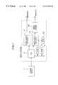
- FIG. 7is a block diagram of an embodiment of the present invention in which the circuit of the invention is applied to a moving picture reproducing system using an MPEG video decoder for decoding a moving picture.
- each of the pixels of a video imageis made up of 8 bits. Even when the amount of information on one pixel is other than 8 bits, the present invention can be embodied in a similar manner.
- FIG. 1shows how to assign the bits of a prior art video signal not containing a key signal.
- This video signalhas an information amount of 8 bits, i.e., its most significant bit (MSB) ly 7 , bits ly 6 , ly 5 , ly 4 , ly 3 , ly 2 , ly 1 , and its least significant bit (LSB) ly 0 .
- MSBmost significant bit
- LSBleast significant bit
- the present embodimentis intended not to add any modification to the prior art recording/transmitting method and to record and transmit a key signal while maintaining compatibility with the prior art.
- the present embodimenthas a bit array such that the information on the format of each of the pixels of the video signal is partly deleted and instead a key signal is assigned thereto.
- the key signalcan be made up of a plurality of bits, it may be made up of only one bit since the key signal is sufficient only to have information (such as a flag) indicative of replacement or non-replacement of an image with another image at the time of image composition.
- the least significant lowest bit ly 0was deleted in the video signal.
- the amount of information of the video signalis not limited to 8 bits but may be any number of bits.
- Shown in FIG. 2is how to assign the bits of a video signal including a key signal when the afore-mentioned method is applied. Since the amount of image data becomes usually enormous, the image data is in many cases subjected to a data compression when it is desired to record or transmit the image. When the image is subjected to data compression and then to data decompression, however, the compressed image cannot always be restored to its original image. In the case of an ordinary video signal, when several of the lower bits of the video signal vary, this will substantially not influence the reproduction of the video signal. However, a change in the key signal may possibly result in erroneous reproduction of the foreground and background. To avoid such a situation, in the present embodiment, the key signal is assigned to the most significant bit (MSB) position 2 k 0 which is the bit least influenced when the data is subjected to the data compression and decompression.
- MSBmost significant bit
- the key signalhas a value indicating that the video pixel in question refers to a background
- the pixelis replaced by a foreground video image in its image combination mode and thus video information on the pixel becomes unnecessary.
- the video information 301 corresponding to one of the pixels of an imageis assumed to have an information amount of 8 bits
- the video information 301can take values of 0-255 and the video information 302 corresponding to the video information 301 but deleted by one bit can take values of 0-127.
- the key signalhas a value of “1”. Therefore, “1” is set at the highest bit position and the values of the bits of the video signal are added by an offset value of 128 according to the assignment of the bits of the video signal including the afore-mentioned key signal to be converted to information 303 having a range of values of 128-255.
- the key signalWhen the pixel corresponds to part of a background of the image, the key signal has a value of “0” and its video information which becomes unnecessary at the time of image combination is also previously set at a value of 0, which results in that a video signal 304 corresponding to the background has a value of 0 and thus such information which takes values of 1-127 becomes absent at the time of coding.
- the video signalhas values of 1-127 at the coding stage.
- an errortakes place between the original and reproduced images, which results in that there occurs such a situation that the information having taken values of 128-255 as its initial foreground video information 403 takes values of 127 or less (information 401 ) or the information having taken a value of zero as the background key signal takes values of 1 or more (information 402 ).
- a key signal 406 indicative of the backgroundcan be separated from video information 404 containing the foreground key signal by clipping the background key signal and the foreground video information with use of the threshold 400 .
- the key signalindicates the foreground
- the key signal(bit 2 k 0 ) having a value of “1” and indicative of the foreground is deleted, the video signal is expanded or decompressed by a factor of 2, and then restored to the original video information (information 405 ).
- the threshold for separation between the key signal and the video signalis set to selectively have a value of, e.g., 64, 96 or 128 (see FIG. 5 ), even the video signal already subjected to the coding can be adjusted at the time of the decoding.
- FIG. 5is a diagram for explaining a variation in a video signal when image data is compressed and decompressed in such a manner as mentioned above as well as a spatial phenomenon which possibly takes place during the compression and decompression. Also shown in FIG. 5 are an image 502 having a foreground 504 and also having a key signal indicative of replacement of a background 503 to be replaced by another image at the time of image combination, as well as a video signal level (more particularly, luminance signal level) corresponding to any one line 501 in the image.
- a video signal levelmore particularly, luminance signal level
- the video signal 505 corresponding to zones of 50 b - 50 c and 50 d - 50 ecorresponds to part of the foreground
- the video signal 505has values higher than a thershold 128
- the video signal 505 corresponding to zones of 50 a - 50 b , 50 c - 50 d and 50 e - 50 f other than the above zones 50 b - 50 c and 50 d - 50 ehas a value of 0.
- a video signal 506 subjected to a data compression/decompressionhas an error with respect to the video signal 505 of the original image.
- suitable thresholds 509 - 511are set to separate the key signal from the video signal.
- these thresholdsare critically set, there may occur levels 507 and 508 such that the key signal cannot be correctly separated from the video signal.
- means for adjusting the key signalis provided so as to allow selection of expansion or non-expansion of the background key signal in the decoding mode.
- the word “expansion” of the background key signalmeans that image data is subjected to a line or raster scan while key signals of pixels adjacent thereto are referred to, so that, if either one or both of the adjacent key signals indicate the background, then the key signal of the current pixel is also regarded to have a value indicative of the background. This enables the key signal erroneously reproduced at the border between the background and foreground to be appropriately adjusted.
- a key-signal enable/disable signalindicates whether an input video signal contains a key signal or is an ordinary video signal not containing the key signal, and is discriminated from the input video signal by a CPU 2 , explained later.
- a key-signal expansion enable/disable signalspecifies the presence or absence of key signal expansion.
- a threshold change-over signalis used to change a threshold for use in separation between the key signal and video information.
- the operation of the video signal reproducing circuit 60will be explained in conjunction with a flow of data.
- the key signal enable/disable signal received from the CPU 2is a disable indication, i.e., that the input video signal contains no key signal
- the input video signalis selected at a video signal change-over circuit 605 , delayed at a delay circuit 607 , and then supplied as it is to a YC-RGB conversion circuit 611 and a combining circuit 612 .
- the foreground key signalis selected in a key-signal change-over circuit 606 due to the key-signal enable/disable signal indicative of the disable and delayed at a delay circuit 608 , and then applied to a key-signal expansion circuit 610 of the next stage.
- the key signalis also delayed at a delay circuit 609 and then applied to the key-signal expansion circuit 610 , three inputs to the key-signal expansion circuit 610 all indicate the foreground key signals and the key-signal expansion enable/disable signal becomes invalid, whereby the foreground key signal is supplied from the key-signal expansion circuit 610 to the combining circuit 612 as it is.
- the key-signal enable/disable signalindicates the enable, i.e., that the input video signal contains the key signal
- 8 bits of the input video signalare separately divided into the key signal and the video signal in accordance with the aforementioned decoding procedure using the threshold. More in detail, the video signal is first subjected at a clipping circuit 603 to a clipping operation at values of 128-256. At this time, if the input video signal has values of 1-127 , then the clipping circuit 603 regards the input video signal to have a value of 128.
- the video signal subjected to the clipping operationis corrected by a correction circuit 604 so that values of 128-256 correspond to 0-254. This correction is carried out by an arithmetic operation such that “128” is subtracted from the values clipped by the clipping circuit 603 and then multiplied by 2.
- the video information subjected to the correctionis selected at the video signal change-over circuit 605 , delayed at the delay circuit 607 and supplied to the YC-RGB conversion circuit 611 where conversion from Y (luminance) and C (chrominance) signals to RGB (red, green and blue) signals is carried out.
- the video informationis combined with a border color signal of, e.g., blue set by the CPU on the basis of the key signal received from the key-signal expansion circuit 610 to generate an output video signal which in turn is output from the combining circuit 612 to such a monitor display unit as a CRT.
- the key-signal enable/disable signalWhen the key-signal enable/disable signal is enable, extraction of the key signal from the input video signal is simultaneously carried out. That is, the input video signal is compared with the threshold at a comparison circuit 602 . Used as the threshold is the value of, e.g., 64, 96 or 128 selected by a threshold change-over signal previously specified in a threshold change-over circuit 601 . As a result of the comparison between the input video signal and the threshold, when determining that the input video signal is larger than the threshold, the comparison circuit 602 outputs the foreground key signal; whereas, when determining that the input video signal is smaller than the threshold, the comparison circuit 602 outputs the background key signal.
- the thresholdUsed as the threshold is the value of, e.g., 64, 96 or 128 selected by a threshold change-over signal previously specified in a threshold change-over circuit 601 .
- the key signalis selected at the key-signal change-over circuit 606 and applied directly to the key-signal expansion circuit 610 , or delayed at the delay circuit 608 or at the delay circuits 608 and 609 and then applied to the key-signal expansion circuit 610 .
- the output of the delay circuit 608is the key signal of the current pixel.
- the output of the key-signal change-over circuit 606 and the output of the delay circuit 609are the key signals of pixels at its left-hand and right-hand adjacent to the pixel of the key signal corresponding to the output of the delay circuit 608 .
- the key-signal expansion circuit 610refers to the key signals of the left/right adjacent pixels and the key signal of the current pixel, outputs the foreground key signal only when all of these key signals indicate the foreground and otherwise outputs the background key signal, thus realizing the expansion of the background key signal.
- FIG. 7Shown in FIG. 7 is a block diagram of an embodiment of the present invention when the reproduction circuit of FIG. 6 is applied to such a moving picture reproduction system that uses an MPEG video decoder (moving picture decoder) 10 based on video specifications called MPEG (moving picture experts group).
- MPEGmoving picture experts group
- the component Ywhich is made up of, e.g., 8 bits, is shifted toward the LSB side sequentially by one bit and “1” is set at the MSB using a shift register. Through this shifting operation, the LSB of the Y component is discarded.
- the chrominance signal Cris output as it is and also applied to a coincidence circuit.
- the coincidence circuitfor detecting a coincidence with a preset background color such as blue or black judges the presence or absence of the background and generates the aforementioned key signal.
- the key signal from the coincidence circuitis applied as a selection instruction signal to a selector circuit which selectively receives an output from the shift circuit and a preset value corresponding to the Y component signal regarded as an all 0 signal.
- the selector circuitselects the Y component having a value of 0; while, when the key signal has a value of “1” indicative of the foreground, the selector circuit selects and outputs the Y component output shifted by the shift circuit and having a value of “1” at the MSB.
- the 3 components issued from the preprocessing circuitare applied to an encoder to be subjected therein to an encoding operation including a known MPEG encoding for data compression, and then recorded in such a recording medium as a CD-ROM as a video signal.
- a signal level difference between the background and foregroundis decompressed in accordance with the principle of FIG. 3 .
- the moving picture reproduction system of the present embodimentincludes a CD-ROM driver 1 for reading out moving picture data stored as compressed/coded in a CD-ROM, a microcomputer (CPU) 2 for separatedly dividing the read-out data into image data and voice data and also for decoding control information, an MPEG audio decoder 3 for decoding the separated moving picture data, an MPEG video decoder 10 for decoding the separated moving picture data, and a video signal reproducing circuit 60 having such a structure as shown in FIG. 6.
- a moving picture signal decoded by the MPEG video decoder 10is sent through the video signal reproducing circuit 60 to such a monitor as a CRT display unit, while the decoded audio signal is sent to an audio amplifier.
- the background image signalmay be provided, e.g., from the CPU 2 .
- a read only memory 4for storing therein a program to be executed by the CPU 2 and fixed data
- a randomly readable/writable memory 5used as a work area of the CPU 2
- a buffer memory (frame memory) 20connected to the MPEG video decoder 10 for temporarily holding the decoded image data therein.
- the MPEG video decoder 10 and the video signal reproducing circuit 60are made in the form of a single chip LSI.
- the LSI chiphas been marketed under the name of MPEG 1 Decoder LSI HD814101F later than the date of the convention priority date claimed for the present application. However, the chip is not intended to be disclosed herein as the prior art.
- the foregoing embodimentshave been explained in the connection with the case where the input video signal is of a digital type, the present invention may be applied even to the case where the input video signal is of an analog type.
- the need for modifying the prior art system for recording or transmitting known data compressed/decompressed datacan be eliminated, the key signal for use in the video signal combining or composition can be recorded or transmitted as part of the video signal, and the key signal can be correctly restored or reproduced without being influenced by an error generated during the data compression/decompression.
Landscapes
- Engineering & Computer Science (AREA)
- Multimedia (AREA)
- Signal Processing (AREA)
- Physics & Mathematics (AREA)
- General Physics & Mathematics (AREA)
- Discrete Mathematics (AREA)
- Theoretical Computer Science (AREA)
- Compression Or Coding Systems Of Tv Signals (AREA)
- Television Signal Processing For Recording (AREA)
Abstract
Description
Claims (10)
Applications Claiming Priority (2)
| Application Number | Priority Date | Filing Date | Title |
|---|---|---|---|
| JP6-283840 | 1994-11-17 | ||
| JP28384094AJP3705447B2 (en) | 1994-11-17 | 1994-11-17 | Image processing method and image processing apparatus |
Publications (1)
| Publication Number | Publication Date |
|---|---|
| US6373892B1true US6373892B1 (en) | 2002-04-16 |
Family
ID=17670847
Family Applications (1)
| Application Number | Title | Priority Date | Filing Date |
|---|---|---|---|
| US08/554,965Expired - Fee RelatedUS6373892B1 (en) | 1994-11-17 | 1995-11-13 | Method for compressing and decompressing moving picture information and video signal processing system |
Country Status (6)
| Country | Link |
|---|---|
| US (1) | US6373892B1 (en) |
| EP (1) | EP0713332B1 (en) |
| JP (1) | JP3705447B2 (en) |
| KR (1) | KR100391994B1 (en) |
| CN (1) | CN1105457C (en) |
| DE (1) | DE69516244T2 (en) |
Cited By (16)
| Publication number | Priority date | Publication date | Assignee | Title |
|---|---|---|---|---|
| US20020071556A1 (en)* | 2000-12-07 | 2002-06-13 | Moskowitz Scott A. | System and methods for permitting open access to data objects and for securing data within the data objects |
| US20030200439A1 (en)* | 2002-04-17 | 2003-10-23 | Moskowitz Scott A. | Methods, systems and devices for packet watermarking and efficient provisioning of bandwidth |
| US20040086119A1 (en)* | 1998-03-24 | 2004-05-06 | Moskowitz Scott A. | Method for combining transfer functions with predetermined key creation |
| US20040243540A1 (en)* | 2000-09-07 | 2004-12-02 | Moskowitz Scott A. | Method and device for monitoring and analyzing signals |
| US20060101269A1 (en)* | 1996-07-02 | 2006-05-11 | Wistaria Trading, Inc. | Method and system for digital watermarking |
| US20060140403A1 (en)* | 1998-04-02 | 2006-06-29 | Moskowitz Scott A | Multiple transform utilization and application for secure digital watermarking |
| US20060285722A1 (en)* | 1996-07-02 | 2006-12-21 | Moskowitz Scott A | Optimization methods for the insertion, protection, and detection of digital watermarks in digitized data |
| US20070011458A1 (en)* | 1996-07-02 | 2007-01-11 | Scott A. Moskowitz | Optimization methods for the insertion, protection, and detection of digital watermarks in digitized data |
| US20070028113A1 (en)* | 1999-12-07 | 2007-02-01 | Moskowitz Scott A | Systems, methods and devices for trusted transactions |
| US20070064940A1 (en)* | 1999-03-24 | 2007-03-22 | Blue Spike, Inc. | Utilizing data reduction in steganographic and cryptographic systems |
| US20070079131A1 (en)* | 1996-12-20 | 2007-04-05 | Wistaria Trading, Inc. | Linear predictive coding implementation of digital watermarks |
| US7346472B1 (en) | 2000-09-07 | 2008-03-18 | Blue Spike, Inc. | Method and device for monitoring and analyzing signals |
| US7475246B1 (en) | 1999-08-04 | 2009-01-06 | Blue Spike, Inc. | Secure personal content server |
| US20090037740A1 (en)* | 1996-07-02 | 2009-02-05 | Wistaria Trading, Inc. | Optimization methods for the insertion, protection, and detection of digital watermarks in digital data |
| US7568100B1 (en) | 1995-06-07 | 2009-07-28 | Wistaria Trading, Inc. | Steganographic method and device |
| US8271795B2 (en) | 2000-09-20 | 2012-09-18 | Blue Spike, Inc. | Security based on subliminal and supraliminal channels for data objects |
Families Citing this family (2)
| Publication number | Priority date | Publication date | Assignee | Title |
|---|---|---|---|---|
| JP2001036801A (en)* | 1999-07-23 | 2001-02-09 | Sharp Corp | Imaging device |
| JP4649147B2 (en)* | 2004-08-31 | 2011-03-09 | 株式会社東芝 | Ultrasonic diagnostic equipment |
Citations (12)
| Publication number | Priority date | Publication date | Assignee | Title |
|---|---|---|---|---|
| US4689682A (en)* | 1986-10-24 | 1987-08-25 | The Grass Valley Group, Inc. | Method and apparatus for carrying out television special effects |
| US4689681A (en)* | 1986-10-24 | 1987-08-25 | The Grass Valley Group, Inc. | Television special effects system |
| US4700232A (en)* | 1986-10-24 | 1987-10-13 | Grass Valley Group, Inc. | Interpolator for television special effects system |
| US4774507A (en) | 1984-05-07 | 1988-09-27 | Nec Corporation | Special video effect system |
| US4777598A (en)* | 1985-03-22 | 1988-10-11 | Quantel Limited | Image processing systems and methods |
| US4827253A (en)* | 1987-05-18 | 1989-05-02 | Dubner Computer Systems, Inc. | Video compositing using a software linear keyer |
| US4831447A (en)* | 1987-11-16 | 1989-05-16 | The Grass Valley Group, Inc. | Method and apparatus for anti-aliasing an image boundary during video special effects |
| US4875097A (en)* | 1986-10-24 | 1989-10-17 | The Grass Valley Group, Inc. | Perspective processing of a video signal |
| WO1991007845A1 (en) | 1989-11-22 | 1991-05-30 | Rank Cintel Limited | Storage of digital image composition control signal |
| US5121210A (en) | 1989-10-27 | 1992-06-09 | Nec Corporation | Video composing system using special effect apparatus |
| US5561723A (en)* | 1992-03-09 | 1996-10-01 | Tektronix, Inc. | Localized image compression calculation method and apparatus to control anti-aliasing filtering in 3-D manipulation of 2-D video images |
| US5570197A (en)* | 1993-06-01 | 1996-10-29 | Matsushita Electric Industrial Co., Ltd. | Apparatus for further compressing and recording encoded digital video data streams |
- 1994
- 1994-11-17JPJP28384094Apatent/JP3705447B2/ennot_activeExpired - Fee Related
- 1995
- 1995-11-08EPEP95117619Apatent/EP0713332B1/ennot_activeExpired - Lifetime
- 1995-11-08DEDE69516244Tpatent/DE69516244T2/ennot_activeExpired - Lifetime
- 1995-11-13USUS08/554,965patent/US6373892B1/ennot_activeExpired - Fee Related
- 1995-11-14KRKR1019950041173Apatent/KR100391994B1/ennot_activeExpired - Fee Related
- 1995-11-17CNCN95119724Apatent/CN1105457C/ennot_activeExpired - Fee Related
Patent Citations (12)
| Publication number | Priority date | Publication date | Assignee | Title |
|---|---|---|---|---|
| US4774507A (en) | 1984-05-07 | 1988-09-27 | Nec Corporation | Special video effect system |
| US4777598A (en)* | 1985-03-22 | 1988-10-11 | Quantel Limited | Image processing systems and methods |
| US4689682A (en)* | 1986-10-24 | 1987-08-25 | The Grass Valley Group, Inc. | Method and apparatus for carrying out television special effects |
| US4689681A (en)* | 1986-10-24 | 1987-08-25 | The Grass Valley Group, Inc. | Television special effects system |
| US4700232A (en)* | 1986-10-24 | 1987-10-13 | Grass Valley Group, Inc. | Interpolator for television special effects system |
| US4875097A (en)* | 1986-10-24 | 1989-10-17 | The Grass Valley Group, Inc. | Perspective processing of a video signal |
| US4827253A (en)* | 1987-05-18 | 1989-05-02 | Dubner Computer Systems, Inc. | Video compositing using a software linear keyer |
| US4831447A (en)* | 1987-11-16 | 1989-05-16 | The Grass Valley Group, Inc. | Method and apparatus for anti-aliasing an image boundary during video special effects |
| US5121210A (en) | 1989-10-27 | 1992-06-09 | Nec Corporation | Video composing system using special effect apparatus |
| WO1991007845A1 (en) | 1989-11-22 | 1991-05-30 | Rank Cintel Limited | Storage of digital image composition control signal |
| US5561723A (en)* | 1992-03-09 | 1996-10-01 | Tektronix, Inc. | Localized image compression calculation method and apparatus to control anti-aliasing filtering in 3-D manipulation of 2-D video images |
| US5570197A (en)* | 1993-06-01 | 1996-10-29 | Matsushita Electric Industrial Co., Ltd. | Apparatus for further compressing and recording encoded digital video data streams |
Cited By (100)
| Publication number | Priority date | Publication date | Assignee | Title |
|---|---|---|---|---|
| US20110069864A1 (en)* | 1995-06-07 | 2011-03-24 | Scott Moskowitz | Steganographic method and device |
| US8467525B2 (en) | 1995-06-07 | 2013-06-18 | Wistaria Trading, Inc. | Steganographic method and device |
| US8549305B2 (en) | 1995-06-07 | 2013-10-01 | Wistaria Trading, Inc. | Steganographic method and device |
| US7568100B1 (en) | 1995-06-07 | 2009-07-28 | Wistaria Trading, Inc. | Steganographic method and device |
| US8238553B2 (en) | 1995-06-07 | 2012-08-07 | Wistaria Trading, Inc | Steganographic method and device |
| US8046841B2 (en) | 1995-06-07 | 2011-10-25 | Wistaria Trading, Inc. | Steganographic method and device |
| US7761712B2 (en) | 1995-06-07 | 2010-07-20 | Wistaria Trading, Inc. | Steganographic method and device |
| US8265276B2 (en) | 1996-01-17 | 2012-09-11 | Moskowitz Scott A | Method for combining transfer functions and predetermined key creation |
| US9021602B2 (en) | 1996-01-17 | 2015-04-28 | Scott A. Moskowitz | Data protection method and device |
| US8930719B2 (en) | 1996-01-17 | 2015-01-06 | Scott A. Moskowitz | Data protection method and device |
| US9104842B2 (en) | 1996-01-17 | 2015-08-11 | Scott A. Moskowitz | Data protection method and device |
| US9171136B2 (en) | 1996-01-17 | 2015-10-27 | Wistaria Trading Ltd | Data protection method and device |
| US9191206B2 (en) | 1996-01-17 | 2015-11-17 | Wistaria Trading Ltd | Multiple transform utilization and application for secure digital watermarking |
| US9191205B2 (en) | 1996-01-17 | 2015-11-17 | Wistaria Trading Ltd | Multiple transform utilization and application for secure digital watermarking |
| US7987371B2 (en) | 1996-07-02 | 2011-07-26 | Wistaria Trading, Inc. | Optimization methods for the insertion, protection, and detection of digital watermarks in digital data |
| US7844074B2 (en) | 1996-07-02 | 2010-11-30 | Wistaria Trading, Inc. | Optimization methods for the insertion, protection, and detection of digital watermarks in digitized data |
| US7343492B2 (en) | 1996-07-02 | 2008-03-11 | Wistaria Trading, Inc. | Method and system for digital watermarking |
| US8307213B2 (en) | 1996-07-02 | 2012-11-06 | Wistaria Trading, Inc. | Method and system for digital watermarking |
| US7362775B1 (en) | 1996-07-02 | 2008-04-22 | Wistaria Trading, Inc. | Exchange mechanisms for digital information packages with bandwidth securitization, multichannel digital watermarks, and key management |
| US20080151934A1 (en)* | 1996-07-02 | 2008-06-26 | Wistaria Trading, Inc. | Exchange mechanisms for digital information packages with bandwidth securitization, multichannel digital watermarks, and key management |
| US7409073B2 (en) | 1996-07-02 | 2008-08-05 | Wistaria Trading, Inc. | Optimization methods for the insertion, protection, and detection of digital watermarks in digitized data |
| US7457962B2 (en) | 1996-07-02 | 2008-11-25 | Wistaria Trading, Inc | Optimization methods for the insertion, protection, and detection of digital watermarks in digitized data |
| US8281140B2 (en) | 1996-07-02 | 2012-10-02 | Wistaria Trading, Inc | Optimization methods for the insertion, protection, and detection of digital watermarks in digital data |
| US20090037740A1 (en)* | 1996-07-02 | 2009-02-05 | Wistaria Trading, Inc. | Optimization methods for the insertion, protection, and detection of digital watermarks in digital data |
| US20060101269A1 (en)* | 1996-07-02 | 2006-05-11 | Wistaria Trading, Inc. | Method and system for digital watermarking |
| US20070113094A1 (en)* | 1996-07-02 | 2007-05-17 | Wistaria Trading, Inc. | Method and system for digital watermarking |
| US8774216B2 (en) | 1996-07-02 | 2014-07-08 | Wistaria Trading, Inc. | Exchange mechanisms for digital information packages with bandwidth securitization, multichannel digital watermarks, and key management |
| US8175330B2 (en) | 1996-07-02 | 2012-05-08 | Wistaria Trading, Inc. | Optimization methods for the insertion, protection, and detection of digital watermarks in digitized data |
| US20100002904A1 (en)* | 1996-07-02 | 2010-01-07 | Wistaria Trading, Inc. | Optimization methods for the insertion, protection, and detection of digital watermarks in digitized data |
| US7647502B2 (en) | 1996-07-02 | 2010-01-12 | Wistaria Trading, Inc. | Optimization methods for the insertion, protection, and detection of digital watermarks in digital data |
| US9070151B2 (en) | 1996-07-02 | 2015-06-30 | Blue Spike, Inc. | Systems, methods and devices for trusted transactions |
| US8161286B2 (en) | 1996-07-02 | 2012-04-17 | Wistaria Trading, Inc. | Method and system for digital watermarking |
| US8121343B2 (en) | 1996-07-02 | 2012-02-21 | Wistaria Trading, Inc | Optimization methods for the insertion, protection, and detection of digital watermarks in digitized data |
| US20100077220A1 (en)* | 1996-07-02 | 2010-03-25 | Moskowitz Scott A | Optimization methods for the insertion, protection, and detection of digital watermarks in digital data |
| US7991188B2 (en) | 1996-07-02 | 2011-08-02 | Wisteria Trading, Inc. | Optimization methods for the insertion, protection, and detection of digital watermarks in digital data |
| US7953981B2 (en) | 1996-07-02 | 2011-05-31 | Wistaria Trading, Inc. | Optimization methods for the insertion, protection, and detection of digital watermarks in digital data |
| US9830600B2 (en) | 1996-07-02 | 2017-11-28 | Wistaria Trading Ltd | Systems, methods and devices for trusted transactions |
| US7770017B2 (en) | 1996-07-02 | 2010-08-03 | Wistaria Trading, Inc. | Method and system for digital watermarking |
| US7779261B2 (en) | 1996-07-02 | 2010-08-17 | Wistaria Trading, Inc. | Method and system for digital watermarking |
| US9843445B2 (en) | 1996-07-02 | 2017-12-12 | Wistaria Trading Ltd | System and methods for permitting open access to data objects and for securing data within the data objects |
| US7830915B2 (en) | 1996-07-02 | 2010-11-09 | Wistaria Trading, Inc. | Methods and systems for managing and exchanging digital information packages with bandwidth securitization instruments |
| US9258116B2 (en) | 1996-07-02 | 2016-02-09 | Wistaria Trading Ltd | System and methods for permitting open access to data objects and for securing data within the data objects |
| US7877609B2 (en) | 1996-07-02 | 2011-01-25 | Wistaria Trading, Inc. | Optimization methods for the insertion, protection, and detection of digital watermarks in digital data |
| US20070011458A1 (en)* | 1996-07-02 | 2007-01-11 | Scott A. Moskowitz | Optimization methods for the insertion, protection, and detection of digital watermarks in digitized data |
| US7930545B2 (en) | 1996-07-02 | 2011-04-19 | Wistaria Trading, Inc. | Optimization methods for the insertion, protection, and detection of digital watermarks in digital data |
| US20060285722A1 (en)* | 1996-07-02 | 2006-12-21 | Moskowitz Scott A | Optimization methods for the insertion, protection, and detection of digital watermarks in digitized data |
| US7730317B2 (en) | 1996-12-20 | 2010-06-01 | Wistaria Trading, Inc. | Linear predictive coding implementation of digital watermarks |
| US20070079131A1 (en)* | 1996-12-20 | 2007-04-05 | Wistaria Trading, Inc. | Linear predictive coding implementation of digital watermarks |
| US8225099B2 (en)* | 1996-12-20 | 2012-07-17 | Wistaria Trading, Inc. | Linear predictive coding implementation of digital watermarks |
| US20040086119A1 (en)* | 1998-03-24 | 2004-05-06 | Moskowitz Scott A. | Method for combining transfer functions with predetermined key creation |
| US7664263B2 (en) | 1998-03-24 | 2010-02-16 | Moskowitz Scott A | Method for combining transfer functions with predetermined key creation |
| US7738659B2 (en) | 1998-04-02 | 2010-06-15 | Moskowitz Scott A | Multiple transform utilization and application for secure digital watermarking |
| US8542831B2 (en) | 1998-04-02 | 2013-09-24 | Scott A. Moskowitz | Multiple transform utilization and application for secure digital watermarking |
| US20060140403A1 (en)* | 1998-04-02 | 2006-06-29 | Moskowitz Scott A | Multiple transform utilization and application for secure digital watermarking |
| US8781121B2 (en) | 1999-03-24 | 2014-07-15 | Blue Spike, Inc. | Utilizing data reduction in steganographic and cryptographic systems |
| US20070064940A1 (en)* | 1999-03-24 | 2007-03-22 | Blue Spike, Inc. | Utilizing data reduction in steganographic and cryptographic systems |
| US8160249B2 (en) | 1999-03-24 | 2012-04-17 | Blue Spike, Inc. | Utilizing data reduction in steganographic and cryptographic system |
| US7664264B2 (en) | 1999-03-24 | 2010-02-16 | Blue Spike, Inc. | Utilizing data reduction in steganographic and cryptographic systems |
| US9270859B2 (en) | 1999-03-24 | 2016-02-23 | Wistaria Trading Ltd | Utilizing data reduction in steganographic and cryptographic systems |
| US8526611B2 (en) | 1999-03-24 | 2013-09-03 | Blue Spike, Inc. | Utilizing data reduction in steganographic and cryptographic systems |
| US10461930B2 (en) | 1999-03-24 | 2019-10-29 | Wistaria Trading Ltd | Utilizing data reduction in steganographic and cryptographic systems |
| US8171561B2 (en) | 1999-08-04 | 2012-05-01 | Blue Spike, Inc. | Secure personal content server |
| US9710669B2 (en) | 1999-08-04 | 2017-07-18 | Wistaria Trading Ltd | Secure personal content server |
| US8739295B2 (en) | 1999-08-04 | 2014-05-27 | Blue Spike, Inc. | Secure personal content server |
| US9934408B2 (en) | 1999-08-04 | 2018-04-03 | Wistaria Trading Ltd | Secure personal content server |
| US8789201B2 (en) | 1999-08-04 | 2014-07-22 | Blue Spike, Inc. | Secure personal content server |
| US7475246B1 (en) | 1999-08-04 | 2009-01-06 | Blue Spike, Inc. | Secure personal content server |
| US7532725B2 (en) | 1999-12-07 | 2009-05-12 | Blue Spike, Inc. | Systems and methods for permitting open access to data objects and for securing data within the data objects |
| US20070110240A1 (en)* | 1999-12-07 | 2007-05-17 | Blue Spike, Inc. | System and methods for permitting open access to data objects and for securing data within the data objects |
| US10644884B2 (en) | 1999-12-07 | 2020-05-05 | Wistaria Trading Ltd | System and methods for permitting open access to data objects and for securing data within the data objects |
| US8538011B2 (en) | 1999-12-07 | 2013-09-17 | Blue Spike, Inc. | Systems, methods and devices for trusted transactions |
| US10110379B2 (en) | 1999-12-07 | 2018-10-23 | Wistaria Trading Ltd | System and methods for permitting open access to data objects and for securing data within the data objects |
| US20070028113A1 (en)* | 1999-12-07 | 2007-02-01 | Moskowitz Scott A | Systems, methods and devices for trusted transactions |
| US20090190754A1 (en)* | 1999-12-07 | 2009-07-30 | Blue Spike, Inc. | System and methods for permitting open access to data objects and for securing data within the data objects |
| US7813506B2 (en) | 1999-12-07 | 2010-10-12 | Blue Spike, Inc | System and methods for permitting open access to data objects and for securing data within the data objects |
| US8798268B2 (en) | 1999-12-07 | 2014-08-05 | Blue Spike, Inc. | System and methods for permitting open access to data objects and for securing data within the data objects |
| US8265278B2 (en) | 1999-12-07 | 2012-09-11 | Blue Spike, Inc. | System and methods for permitting open access to data objects and for securing data within the data objects |
| US8767962B2 (en) | 1999-12-07 | 2014-07-01 | Blue Spike, Inc. | System and methods for permitting open access to data objects and for securing data within the data objects |
| US8214175B2 (en) | 2000-09-07 | 2012-07-03 | Blue Spike, Inc. | Method and device for monitoring and analyzing signals |
| US20040243540A1 (en)* | 2000-09-07 | 2004-12-02 | Moskowitz Scott A. | Method and device for monitoring and analyzing signals |
| US8712728B2 (en) | 2000-09-07 | 2014-04-29 | Blue Spike Llc | Method and device for monitoring and analyzing signals |
| US7949494B2 (en) | 2000-09-07 | 2011-05-24 | Blue Spike, Inc. | Method and device for monitoring and analyzing signals |
| US7660700B2 (en) | 2000-09-07 | 2010-02-09 | Blue Spike, Inc. | Method and device for monitoring and analyzing signals |
| US7346472B1 (en) | 2000-09-07 | 2008-03-18 | Blue Spike, Inc. | Method and device for monitoring and analyzing signals |
| US8612765B2 (en) | 2000-09-20 | 2013-12-17 | Blue Spike, Llc | Security based on subliminal and supraliminal channels for data objects |
| US8271795B2 (en) | 2000-09-20 | 2012-09-18 | Blue Spike, Inc. | Security based on subliminal and supraliminal channels for data objects |
| US7177429B2 (en)* | 2000-12-07 | 2007-02-13 | Blue Spike, Inc. | System and methods for permitting open access to data objects and for securing data within the data objects |
| US20020071556A1 (en)* | 2000-12-07 | 2002-06-13 | Moskowitz Scott A. | System and methods for permitting open access to data objects and for securing data within the data objects |
| US8224705B2 (en) | 2002-04-17 | 2012-07-17 | Moskowitz Scott A | Methods, systems and devices for packet watermarking and efficient provisioning of bandwidth |
| US20080005571A1 (en)* | 2002-04-17 | 2008-01-03 | Moskowitz Scott A | Methods, systems and devices for packet watermarking and efficient provisioning of bandwidth |
| US7287275B2 (en) | 2002-04-17 | 2007-10-23 | Moskowitz Scott A | Methods, systems and devices for packet watermarking and efficient provisioning of bandwidth |
| US9639717B2 (en) | 2002-04-17 | 2017-05-02 | Wistaria Trading Ltd | Methods, systems and devices for packet watermarking and efficient provisioning of bandwidth |
| US8473746B2 (en) | 2002-04-17 | 2013-06-25 | Scott A. Moskowitz | Methods, systems and devices for packet watermarking and efficient provisioning of bandwidth |
| US20090210711A1 (en)* | 2002-04-17 | 2009-08-20 | Moskowitz Scott A | Methods, systems and devices for packet watermarking and efficient provisioning of bandwidth |
| US8706570B2 (en) | 2002-04-17 | 2014-04-22 | Scott A. Moskowitz | Methods, systems and devices for packet watermarking and efficient provisioning of bandwidth |
| US8104079B2 (en) | 2002-04-17 | 2012-01-24 | Moskowitz Scott A | Methods, systems and devices for packet watermarking and efficient provisioning of bandwidth |
| USRE44222E1 (en) | 2002-04-17 | 2013-05-14 | Scott Moskowitz | Methods, systems and devices for packet watermarking and efficient provisioning of bandwidth |
| US20030200439A1 (en)* | 2002-04-17 | 2003-10-23 | Moskowitz Scott A. | Methods, systems and devices for packet watermarking and efficient provisioning of bandwidth |
| USRE44307E1 (en) | 2002-04-17 | 2013-06-18 | Scott Moskowitz | Methods, systems and devices for packet watermarking and efficient provisioning of bandwidth |
| US10735437B2 (en) | 2002-04-17 | 2020-08-04 | Wistaria Trading Ltd | Methods, systems and devices for packet watermarking and efficient provisioning of bandwidth |
Also Published As
| Publication number | Publication date |
|---|---|
| DE69516244D1 (en) | 2000-05-18 |
| JP3705447B2 (en) | 2005-10-12 |
| EP0713332A1 (en) | 1996-05-22 |
| KR100391994B1 (en) | 2003-11-01 |
| CN1105457C (en) | 2003-04-09 |
| KR960020533A (en) | 1996-06-17 |
| DE69516244T2 (en) | 2001-05-23 |
| JPH08149468A (en) | 1996-06-07 |
| CN1132985A (en) | 1996-10-09 |
| EP0713332B1 (en) | 2000-04-12 |
Similar Documents
| Publication | Publication Date | Title |
|---|---|---|
| US6373892B1 (en) | Method for compressing and decompressing moving picture information and video signal processing system | |
| US5818970A (en) | Image encoding apparatus | |
| US7965858B2 (en) | Data processing apparatus and method | |
| EP1326449B1 (en) | Data decoding method and decoding system | |
| US9167198B2 (en) | Image processing apparatus and image processing method | |
| JP2003528475A (en) | System for detecting redundant images in a video sequence | |
| EP0840517A2 (en) | Video data stream decoding method and apparatus | |
| JP4288398B2 (en) | Image recording apparatus, image reproducing apparatus, and recording medium recording image processing program | |
| AU2003289325A1 (en) | Image encoding device and method, and encoded image decoding device and method | |
| JP3231800B2 (en) | Image encoding apparatus and image encoding method | |
| US6307975B1 (en) | Image coding technique employing shape and texture coding | |
| US6256449B1 (en) | Image encoder and image decoder | |
| EP0726679B1 (en) | Method and device for transmitting compressed picture data | |
| JPH0283578A (en) | Image data display device and image data display method | |
| JPH0646369A (en) | Video signal processor | |
| JPH1155663A (en) | Image transmitter and image transmission method | |
| KR100209680B1 (en) | Additional information recording and reproducing device of magnetic recording medium | |
| JP3354076B2 (en) | Image compression method, image expansion method, image compression device, and image expansion device | |
| TW389020B (en) | Method for coding moving picture information, method for replacing key signal information | |
| JPH06209462A (en) | Recorder | |
| JP2000036750A (en) | Data transmission device and data reproduction device | |
| JPH0785267A (en) | Converting device for the number of quantizing bits | |
| JPH1084530A (en) | Video signal playback device | |
| JPH06314476A (en) | Method and device for reproducing pcm still picture | |
| JPH02262781A (en) | hard copy device |
Legal Events
| Date | Code | Title | Description |
|---|---|---|---|
| AS | Assignment | Owner name:SEGA ENTERPRISES, LTD., JAPAN Free format text:ASSIGNMENT OF ASSIGNORS INTEREST;ASSIGNORS:ICHIEN, TORU;KIMURA, JUNICHI;SAITOH, TADASHI;AND OTHERS;REEL/FRAME:007926/0532 Effective date:19951212 Owner name:HITACHI, LTD., JAPAN Free format text:ASSIGNMENT OF ASSIGNORS INTEREST;ASSIGNORS:ICHIEN, TORU;KIMURA, JUNICHI;SAITOH, TADASHI;AND OTHERS;REEL/FRAME:007926/0532 Effective date:19951212 | |
| AS | Assignment | Owner name:SEGA ENTERPRISES, LTD., JAPAN Free format text:ASSIGNMENT OF ASSIGNORS INTEREST;ASSIGNOR:HITACHI, LTD.;REEL/FRAME:009127/0721 Effective date:19980316 | |
| FEPP | Fee payment procedure | Free format text:PAYOR NUMBER ASSIGNED (ORIGINAL EVENT CODE: ASPN); ENTITY STATUS OF PATENT OWNER: LARGE ENTITY | |
| FPAY | Fee payment | Year of fee payment:4 | |
| FPAY | Fee payment | Year of fee payment:8 | |
| REMI | Maintenance fee reminder mailed | ||
| LAPS | Lapse for failure to pay maintenance fees | ||
| STCH | Information on status: patent discontinuation | Free format text:PATENT EXPIRED DUE TO NONPAYMENT OF MAINTENANCE FEES UNDER 37 CFR 1.362 | |
| FP | Lapsed due to failure to pay maintenance fee | Effective date:20140416 |