US6373611B1 - Digital optical transmitter - Google Patents
Digital optical transmitterDownload PDFInfo
- Publication number
- US6373611B1 US6373611B1US09/102,344US10234498AUS6373611B1US 6373611 B1US6373611 B1US 6373611B1US 10234498 AUS10234498 AUS 10234498AUS 6373611 B1US6373611 B1US 6373611B1
- Authority
- US
- United States
- Prior art keywords
- signal
- digital
- reverse
- optical
- pilot tone
- Prior art date
- Legal status (The legal status is an assumption and is not a legal conclusion. Google has not performed a legal analysis and makes no representation as to the accuracy of the status listed.)
- Expired - Lifetime
Links
- 230000003287optical effectEffects0.000titleclaimsabstractdescription76
- 238000009432framingMethods0.000claimsdescription2
- 239000000835fiberSubstances0.000abstractdescription14
- 230000005540biological transmissionEffects0.000description11
- 238000010586diagramMethods0.000description8
- 238000000034methodMethods0.000description4
- 238000011144upstream manufacturingMethods0.000description4
- 230000001419dependent effectEffects0.000description3
- 230000007423decreaseEffects0.000description2
- 230000003247decreasing effectEffects0.000description2
- 230000015556catabolic processEffects0.000description1
- 238000006243chemical reactionMethods0.000description1
- 238000006731degradation reactionMethods0.000description1
- 230000000593degrading effectEffects0.000description1
- 238000011084recoveryMethods0.000description1
- 230000035945sensitivityEffects0.000description1
Images

Classifications
- H—ELECTRICITY
- H04—ELECTRIC COMMUNICATION TECHNIQUE
- H04B—TRANSMISSION
- H04B10/00—Transmission systems employing electromagnetic waves other than radio-waves, e.g. infrared, visible or ultraviolet light, or employing corpuscular radiation, e.g. quantum communication
- H04B10/07—Arrangements for monitoring or testing transmission systems; Arrangements for fault measurement of transmission systems
- H04B10/075—Arrangements for monitoring or testing transmission systems; Arrangements for fault measurement of transmission systems using an in-service signal
- H04B10/077—Arrangements for monitoring or testing transmission systems; Arrangements for fault measurement of transmission systems using an in-service signal using a supervisory or additional signal
- H04B10/0779—Monitoring line transmitter or line receiver equipment
- H—ELECTRICITY
- H04—ELECTRIC COMMUNICATION TECHNIQUE
- H04B—TRANSMISSION
- H04B10/00—Transmission systems employing electromagnetic waves other than radio-waves, e.g. infrared, visible or ultraviolet light, or employing corpuscular radiation, e.g. quantum communication
- H04B10/25—Arrangements specific to fibre transmission
- H04B10/2575—Radio-over-fibre, e.g. radio frequency signal modulated onto an optical carrier
- H04B10/25751—Optical arrangements for CATV or video distribution
- H—ELECTRICITY
- H04—ELECTRIC COMMUNICATION TECHNIQUE
- H04B—TRANSMISSION
- H04B10/00—Transmission systems employing electromagnetic waves other than radio-waves, e.g. infrared, visible or ultraviolet light, or employing corpuscular radiation, e.g. quantum communication
- H04B10/50—Transmitters
- H04B10/501—Structural aspects
- H04B10/503—Laser transmitters
- H04B10/504—Laser transmitters using direct modulation
Definitions
- This inventionrelates generally to fiber optic communications, and more specifically to optical transmitters for use in fiber optic communications.
- Cable television systemstypically include a headend section for receiving satellite signals and demodulating the signals to baseband. The baseband signal is then converted to an optical signal for transmission from the headend section over fiber optic cable.
- Optical transmittersare distributed throughout the cable system for splitting and transmitting optical signals, and optical receivers are provided for receiving the optical signals and converting them to radio frequency (RF) signals that are further transmitted along branches of the system over coaxial cable rather than fiber optic cable.
- Tapsare situated along the coaxial cable to tap off the cable signals to subscribers of the system.
- FIG. 1is a block diagram of a cable television system in accordance with the present invention.
- FIG. 2is an electrical block diagram of an optical transmitter included in the cable television system of FIG. 1 in accordance with the present invention.
- FIG. 3is an electrical block diagram of an optical receiver included in the cable television system of FIG. 1 in accordance with the present invention.
- FIG. 4is a block diagram of a cable television having multiple outputs to subscriber regions in accordance with the present invention.
- FIG. 5is an electrical block diagram of an optical transmitter included in the cable television system of FIG. 4 in accordance with the present invention.
- FIG. 6is an electrical block diagram of an optical receiver included in the cable television system of FIG. 4 in accordance with the present invention.
- FIG. 1shows a communications system, such as a cable television system 100 having both forward and reverse paths, i.e., having the ability to communicate downstream in the forward direction and upstream in the reverse direction.
- the cable television system 100includes a headend 105 for receiving satellite signals that are demodulated to baseband or an intermediate frequency (IF).
- IFintermediate frequency
- the baseband signalis then converted to cable television signals that are routed throughout the system 100 to subscriber equipment 130 , such as set top decoders, televisions, or computers, located in the residences or offices of system subscribers.
- subscriber equipment 130such as set top decoders, televisions, or computers, located in the residences or offices of system subscribers.
- the headend 105can, for instance, convert the baseband signal to an optical signal that is transmitted over fiber optic cable 110 , in which case a remotely located optical node 115 converts the optical signal to an electrical radio frequency (RF) signal for further transmission through the system 100 over coaxial cable 120 .
- RFradio frequency
- Taps 125 located along the cable 120 at various points in the distribution systemsplit off portions of the RF signal for routing to subscriber equipment 130 coupled to subscriber drops provided at the taps 125 .
- the system 100also has reverse transmission capability so that signals, such as data, video, or voice signals, generated by the subscriber equipment 130 can be provided back to the headend 105 for processing.
- the reverse signalstravel through the taps 125 and any nodes 115 and other cable television equipment, e.g., reverse amplifiers, to the headend 105 .
- RE signals generated by the subscriber equipment 130travel to the node 115 , which converts the RF signals to optical signals for transmission over the fiber optic cable 110 to the headend 105 .
- a digital reverse transmitter 200is provided for transmitting digital optical signals to the headend 105 in the reverse direction.
- the transmitter 200can, for instance, be included within the optical node l 15 , although other locations within the cable television system 100 may also include the digital reverse transmitter 200 of the present invention.
- the transmitter 200receives, at an input 202 , an analog information signal that is representative of one or more reverse RF signals from the subscriber equipment 130 .
- the transmitter 200provides a digital optical signal that is generated in accordance with the analog information signal as well as an optional pilot tone that serves to provide a reference level during processing at the headend 105 .
- the digital reverse transmitter 200includes an analog-to-digital (A/D) converter 205 for converting the analog input to a digital signal, i.e., a digital word comprising a particular number of bits, in a conventional manner.
- A/Danalog-to-digital
- the transmitter 200can also include a digital pilot tone generator 210 for providing a digital pilot tone in the form of a number of bits representative of a particular level and frequency.
- the digital pilot tone generator 210could, for instance, include input switches by which the level and frequency could be varied.
- U.S. Pat. No. 5,563,815 to Jonesshows a digital tone oscillator that could be used to implement the generator 210 included in the transmitter 200 of the present invention.
- a summer 215receives the digital information signal from the AID converter 205 and the digital pilot tone signal from the generator 210 and digitally adds the two signals by performing binary addition in a known manner.
- the summed signalis then coupled to a parallel-to-serial (P/S) converter, or a serializer 220 , which receives the parallel inputs representative of the summed signal and converts the inputs into a serial bit stream.
- a laser diode 225is then driven to generate an optical signal in accordance with the serial bit stream.
- the serializer 220can also include a driver for driving the laser diode 225 and frame encoding circuitry for encoding the serialized digital signal into frames of data.
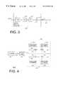
- FIG. 3is a block diagram of an optical receiver 305 for receiving the digital optical signal transmitted by the optical transmitter 200 .
- the receiver 305can be, for instance, located in the headend 105 , although other locations, such as any intervening nodes, may also employ the receiver 305 .
- the receiver 305includes a detector, such as a photodiode 310 , for receiving the digital optical signal transmitted over the fiber optic cable 110 and generating therefrom a serial stream of electrical pulses in accordance with the optical signal.
- the output signals provided by the photodiode 310are coupled to a serial-to-parallel (P/S) converter 315 for generating therefrom a set of parallel outputs corresponding to a digital word.
- P/Sserial-to-parallel
- the receiver 305further includes a digital-to-analog (D/A) converter 320 for converting the signal provided at its digital input to an analog signal in a known manner. Thereafter, the analog signal is processed by a filter 325 to separate the pilot tone signal from the information signal. More specifically, the filter 325 preferably comprises a low pass filter that only passes the fundamental frequency component of the output of the D/A converter 320 . As a result, the digital optical receiver 305 is able to provide at its output a reference signal, i.e., the pilot tone, and an analog signal that approximates the analog information signal initially provided to the optical transmitter 200 . Furthermore, this can be done without encountering many of the problems that arise in prior art designs.
- D/Adigital-to-analog
- optical links in the reverse pathuse amplitude modulation to directly modulate a laser generating a reverse optical signal.
- RF output level of the optical receiveris directly dependent upon the optical modulation index (OMI), which in turn is directly related to the RF drive current, the laser threshold current, and the laser bias current of the laser located in the transmitter. Since the laser bias and threshold currents vary with temperature, which in turn causes temperature variations of the OMI, the RF output level of the optical receiver also varies with temperature.
- OMIoptical modulation index
- the laser within the transmitter 200 of the present inventionis digitally modulated so that the RF level information is encoded according to a bit stream; as a result, variations in the OMI, the laser bias current, the laser threshold current, and the temperature do not affect RF output levels of the optical receiver 305 .
- Prior art optical transmission that use AM modulationalso result in a system in which the linearity of the received optical signal is directly dependent upon the linearity of the transmitting laser and the receiving photodiode. Therefore, non-linearities of those devices can greatly degrade the performance of the reverse path system. Additionally, the non-linear conversion processes of lasers and photodiodes in conventional systems vary with temperature, thus further degrading the performance. Conversely, the digital optical system, i.e., the digital optical transmitter 200 and the digital optical receiver 305 , of the present invention only generates and resolves two amplitude levels rather than a continuum of levels. As a result, linearity requirements of the laser and photodiode are reduced, which results in better performance and less expense.
- Still another advantage of the digital optical transmitter 200 and receiver 305 of the present inventionis that the cable system 100 can, without significant cost or performance penalties, employ an architecture in which fiber stretches deeper into the system 100 .
- the signaldecreases in power as a result of laser noise, Rayleigh backscattering, photodiode shot noise, receiver amplifier noise, unmodulated Fabry-Perot sporadic noise, and post amplifier intrinsic noise.
- CNRcarrier-to-noise ratio
- this problemis mitigated by driving the transmitter laser with more power and/or increasing the receive sensitivity of the receiver photodiode at great expense.
- the system 400includes a headend 105 for generating cable television signals that are split off to subscriber equipment 130 by taps 125 .
- the optical node 415splits off the downstream cable signal for transmission to multiple distribution systems 430 , 435 , or branches. Each branch typically provides service to subscribers located in different geographic regions.
- Upstream reverse signals provided by subscriber equipment 130 in the different branches 430 , 435is transmitted in the form of analog RF signals to the optical node 415 , which combines the signals for further upstream transmission in the form of an optical signal.
- the upstream signals from the different branches 430 , 435can be converted to a digital optical signal in a manner that minimizes or eliminates many of the problems associated with prior art cable television systems.
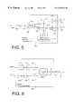
- FIG. 5is an electrical block diagram of an optical transmitter 500 that can, in accordance with the present invention, be used to process multiple analog inputs.
- the transmitter 500receives a first analog input, such as from a first branch 430 of a cable television system 400 , and, at input 503 , the transmitter 500 receives a second analog input, such as from a second branch 435 of the system 400 .
- First and second A/D converters 205 , 505respectively convert the received RF signals to digital information signals that are separately summed, by summers 215 , 515 , with the digital pilot tone.
- serializers 220 , 520Each summed signal is then serialized by serializers 220 , 520 to result in first and second serial bit streams that are representative of the first and second RF signals, respectively, as separately combined with the digital pilot tone.
- bits of the serial bit streamsare interleaved by an interleaver 550 to form a single digital signal that modulates the laser diode 225 .
- a single digital optical signalcan be provided at the output 504 of the transmitter 500 .
- the receiver 605for processing the digital optical signal generated by the transmitter 500 is shown.
- the receiver 605includes a photodiode 310 for generating electrical pulses from the optical signal and a deinterleaver 650 for deinterleaving the signal comprising the electrical pulses.
- the deinterleaver 650Once the deinterleaver 650 has separated the received signal into separate serial bit streams, the outputs are coupled to first and second S/P converters 315 , 615 , first and second D/A converters 320 , 620 , and first and second filters 325 , 625 to recover approximations of the pilot tone and the RF signals that were provided to the transmitter 500 .
- the interleaver 550 and the deinterleaver 650can be implemented using conventional components.
- the interleaver 550could be a framing device capable of implementing a time-domain-multiplexing (TDM) scheme with respect to the incoming bit streams.
- a frame clock(not shown) would be coupled to the interleaver 550 , and one frame would consist of a number of sub-frames equivalent to the number of incoming bit streams.
- a flag bitwould likely be inserted into the frame for identifying the start of the frame.
- the deinterleaver 650is capable of extracting the frame clock signal from the incoming information and recognizing the flag bits indicative of frame starts. Each bit would then be routed to its respective bit stream to recover the original signals.
- the optical transmission systemwould individually convert each reverse signal to a digital signal, add it to the pilot tone, and serialize the combined signal. All serialized signals would then be combined by the interleaver 550 to generate a bit stream for modulating the laser diode 225 (FIG. 5 ).
- the deinterleaver 650would deinterleave the received digital optical signal to provide five serial signals that would be individually processed by S/P converters, D/A converters, and filters to provide five analog outputs as well as an approximation of the pilot tone.
- reverse signals of the same frequencycan be conveniently sent to the beadend 105 over the same return fiber 110 .
- Thisis very important since cable television systems typically only allocate a small amount of bandwidth, e.g., 5-40 MHZ, for return path transmissions, which means that varying the frequency of each return path signal would not be practical.
- the reverse digital transmission system described aboveprovides one or more reverse signals without many of the problems present in prior art systems.
- informationcan be sent from subscribers to the headend in a more reliable and less expensive manner.
Landscapes
- Physics & Mathematics (AREA)
- Engineering & Computer Science (AREA)
- Electromagnetism (AREA)
- Computer Networks & Wireless Communication (AREA)
- Signal Processing (AREA)
- Multimedia (AREA)
- Optics & Photonics (AREA)
- Optical Communication System (AREA)
- Two-Way Televisions, Distribution Of Moving Picture Or The Like (AREA)
Abstract
Description
This invention relates generally to fiber optic communications, and more specifically to optical transmitters for use in fiber optic communications.
Cable television systems typically include a headend section for receiving satellite signals and demodulating the signals to baseband. The baseband signal is then converted to an optical signal for transmission from the headend section over fiber optic cable. Optical transmitters are distributed throughout the cable system for splitting and transmitting optical signals, and optical receivers are provided for receiving the optical signals and converting them to radio frequency (RF) signals that are further transmitted along branches of the system over coaxial cable rather than fiber optic cable. Taps are situated along the coaxial cable to tap off the cable signals to subscribers of the system.
Various factors influence the ability to accurately transmit and receive optical signals within a cable television system. As the length of fiber optic cable within a system increases, for example, signal losses also increase. Furthermore, temperature fluctuations, which cause variation in the optical modulation index of the optical transmitter, can result in variation of the radio frequency (RF) output level of the optical receiver. Signal distortions can be caused by non-linearities in the laser and photodiode of the optical transmitter.
Although these problems can be mitigated by employing expensive techniques, e.g., decreasing fiber lengths between optical nodes, such techniques may prohibitively increase costs to both subscribers and service providers. Thus, what is needed is a better way to provide reliable and accurate transmission of optical signals within a cable television system.
FIG. 1 is a block diagram of a cable television system in accordance with the present invention.
FIG. 2 is an electrical block diagram of an optical transmitter included in the cable television system of FIG. 1 in accordance with the present invention.
FIG. 3 is an electrical block diagram of an optical receiver included in the cable television system of FIG. 1 in accordance with the present invention.
FIG. 4 is a block diagram of a cable television having multiple outputs to subscriber regions in accordance with the present invention.
FIG. 5 is an electrical block diagram of an optical transmitter included in the cable television system of FIG. 4 in accordance with the present invention.
FIG. 6 is an electrical block diagram of an optical receiver included in the cable television system of FIG. 4 in accordance with the present invention.
FIG. 1 shows a communications system, such as acable television system 100 having both forward and reverse paths, i.e., having the ability to communicate downstream in the forward direction and upstream in the reverse direction. Thecable television system 100 includes a headend105 for receiving satellite signals that are demodulated to baseband or an intermediate frequency (IF). The baseband signal is then converted to cable television signals that are routed throughout thesystem 100 tosubscriber equipment 130, such as set top decoders, televisions, or computers, located in the residences or offices of system subscribers. Theheadend 105 can, for instance, convert the baseband signal to an optical signal that is transmitted over fiberoptic cable 110, in which case a remotely locatedoptical node 115 converts the optical signal to an electrical radio frequency (RF) signal for further transmission through thesystem 100 overcoaxial cable 120.Taps 125 located along thecable 120 at various points in the distribution system split off portions of the RF signal for routing tosubscriber equipment 130 coupled to subscriber drops provided at thetaps 125.
Thesystem 100, as mentioned, also has reverse transmission capability so that signals, such as data, video, or voice signals, generated by thesubscriber equipment 130 can be provided back to theheadend 105 for processing. The reverse signals travel through thetaps 125 and anynodes 115 and other cable television equipment, e.g., reverse amplifiers, to theheadend 105. In the configuration shown in FIG. 1, RE signals generated by thesubscriber equipment 130 travel to thenode 115, which converts the RF signals to optical signals for transmission over the fiberoptic cable 110 to theheadend 105.
Referring to FIG. 2, a digitalreverse transmitter 200 is provided for transmitting digital optical signals to theheadend 105 in the reverse direction. Thetransmitter 200 can, for instance, be included within the optical node l15, although other locations within thecable television system 100 may also include the digitalreverse transmitter 200 of the present invention. Thetransmitter 200 receives, at aninput 202, an analog information signal that is representative of one or more reverse RF signals from thesubscriber equipment 130. At itsoutput 204, thetransmitter 200 provides a digital optical signal that is generated in accordance with the analog information signal as well as an optional pilot tone that serves to provide a reference level during processing at theheadend 105.
More specifically, thedigital reverse transmitter 200 includes an analog-to-digital (A/D)converter 205 for converting the analog input to a digital signal, i.e., a digital word comprising a particular number of bits, in a conventional manner. The resolution of theAID converter 205, of course, is dependent upon transmitter design parameters. Thetransmitter 200 can also include a digitalpilot tone generator 210 for providing a digital pilot tone in the form of a number of bits representative of a particular level and frequency. The digitalpilot tone generator 210 could, for instance, include input switches by which the level and frequency could be varied. U.S. Pat. No. 5,563,815 to Jones, the teachings of which are hereby incorporated by reference, shows a digital tone oscillator that could be used to implement thegenerator 210 included in thetransmitter 200 of the present invention.
Asummer 215 receives the digital information signal from the AIDconverter 205 and the digital pilot tone signal from thegenerator 210 and digitally adds the two signals by performing binary addition in a known manner. The summed signal is then coupled to a parallel-to-serial (P/S) converter, or aserializer 220, which receives the parallel inputs representative of the summed signal and converts the inputs into a serial bit stream. Alaser diode 225 is then driven to generate an optical signal in accordance with the serial bit stream. It will be appreciated that theserializer 220 can also include a driver for driving thelaser diode 225 and frame encoding circuitry for encoding the serialized digital signal into frames of data.
FIG. 3 is a block diagram of anoptical receiver 305 for receiving the digital optical signal transmitted by theoptical transmitter 200. Thereceiver 305 can be, for instance, located in theheadend 105, although other locations, such as any intervening nodes, may also employ thereceiver 305. Thereceiver 305 includes a detector, such as aphotodiode 310, for receiving the digital optical signal transmitted over the fiberoptic cable 110 and generating therefrom a serial stream of electrical pulses in accordance with the optical signal. The output signals provided by thephotodiode 310 are coupled to a serial-to-parallel (P/S)converter 315 for generating therefrom a set of parallel outputs corresponding to a digital word. Thereceiver 305 further includes a digital-to-analog (D/A)converter 320 for converting the signal provided at its digital input to an analog signal in a known manner. Thereafter, the analog signal is processed by a filter325 to separate the pilot tone signal from the information signal. More specifically, the filter325 preferably comprises a low pass filter that only passes the fundamental frequency component of the output of the D/A converter 320. As a result, the digitaloptical receiver 305 is able to provide at its output a reference signal, i.e., the pilot tone, and an analog signal that approximates the analog information signal initially provided to theoptical transmitter 200. Furthermore, this can be done without encountering many of the problems that arise in prior art designs.
In conventional cable television systems, optical links in the reverse path use amplitude modulation to directly modulate a laser generating a reverse optical signal. As a result, RF output level of the optical receiver is directly dependent upon the optical modulation index (OMI), which in turn is directly related to the RF drive current, the laser threshold current, and the laser bias current of the laser located in the transmitter. Since the laser bias and threshold currents vary with temperature, which in turn causes temperature variations of the OMI, the RF output level of the optical receiver also varies with temperature. However, the laser within thetransmitter 200 of the present invention is digitally modulated so that the RF level information is encoded according to a bit stream; as a result, variations in the OMI, the laser bias current, the laser threshold current, and the temperature do not affect RF output levels of theoptical receiver 305.
Prior art optical transmission that use AM modulation also result in a system in which the linearity of the received optical signal is directly dependent upon the linearity of the transmitting laser and the receiving photodiode. Therefore, non-linearities of those devices can greatly degrade the performance of the reverse path system. Additionally, the non-linear conversion processes of lasers and photodiodes in conventional systems vary with temperature, thus further degrading the performance. Conversely, the digital optical system, i.e., the digitaloptical transmitter 200 and the digitaloptical receiver 305, of the present invention only generates and resolves two amplitude levels rather than a continuum of levels. As a result, linearity requirements of the laser and photodiode are reduced, which results in better performance and less expense.
Another problem associated with conventional cable television systems is that reverse pilot tones are seldom used due to the complications and costs. When such pilot tones are used, an additional oscillator, which is not digital, is generally located outside the transmitter and is susceptible to temperature variations. The oscillator signal is combined with the analog RF signal, and the combined signal is used to modulate the laser diode current to provide an optical output. Prior art pilot tones are used by an optical transmitter to ensure that there is always a minimum RF signal modulating the laser, thereby decreasing the spurious noise generated by the laser, and by an optical receiver for gain control purposes. However, since oscillator output level drifts with temperature, the RF output level of the optical receiver will also drift with temperature so that gain control is essentially useless. As mentioned above, use of the combined digital pilot tone and digital information signal according to the present invention solves the prior art temperature dependency problems. At the same time, the digital pilot tone can be used by thetransmitter 200 to modulate the laser even when no RF input is present.
Still another advantage of the digitaloptical transmitter 200 andreceiver 305 of the present invention is that thecable system 100 can, without significant cost or performance penalties, employ an architecture in which fiber stretches deeper into thesystem 100. As a cable television signal travels along afiber optic cable 110, the signal decreases in power as a result of laser noise, Rayleigh backscattering, photodiode shot noise, receiver amplifier noise, unmodulated Fabry-Perot sporadic noise, and post amplifier intrinsic noise. These factors cause the carrier-to-noise ratio (CNR) to decrease. Conventionally, this problem is mitigated by driving the transmitter laser with more power and/or increasing the receive sensitivity of the receiver photodiode at great expense. However, this need not be done in asystem 100 according to the present invention since the noise sources and corresponding signal degradation resulting from increased fiber lengths does not affect recovery of information to the same extent as in prior art systems.
Referring next to FIG. 4, a modifiedcable television system 400 is depicted. Thesystem 400 includes aheadend 105 for generating cable television signals that are split off tosubscriber equipment 130 bytaps 125. However, in thesystem 400, theoptical node 415 splits off the downstream cable signal for transmission tomultiple distribution systems subscriber equipment 130 in thedifferent branches optical node 415, which combines the signals for further upstream transmission in the form of an optical signal. According to the present invention, the upstream signals from thedifferent branches
FIG. 5 is an electrical block diagram of anoptical transmitter 500 that can, in accordance with the present invention, be used to process multiple analog inputs. Atinput 502, thetransmitter 500 receives a first analog input, such as from afirst branch 430 of acable television system 400, and, atinput 503, thetransmitter 500 receives a second analog input, such as from asecond branch 435 of thesystem 400. First and second A/D converters summers serializers interleaver 550 to form a single digital signal that modulates thelaser diode 225. As a result, a single digital optical signal can be provided at theoutput 504 of thetransmitter 500.
Referring to FIG. 6, anoptical receiver 605 for processing the digital optical signal generated by thetransmitter 500 is shown. Thereceiver 605 includes aphotodiode 310 for generating electrical pulses from the optical signal and adeinterleaver 650 for deinterleaving the signal comprising the electrical pulses. Once thedeinterleaver 650 has separated the received signal into separate serial bit streams, the outputs are coupled to first and second S/P converters A converters second filters 325,625 to recover approximations of the pilot tone and the RF signals that were provided to thetransmitter 500.
It will be appreciated that theinterleaver 550 and thedeinterleaver 650 can be implemented using conventional components. Typically, theinterleaver 550 could be a framing device capable of implementing a time-domain-multiplexing (TDM) scheme with respect to the incoming bit streams. In such an implementation, a frame clock (not shown) would be coupled to theinterleaver 550, and one frame would consist of a number of sub-frames equivalent to the number of incoming bit streams. A flag bit would likely be inserted into the frame for identifying the start of the frame. Thedeinterleaver 650 is capable of extracting the frame clock signal from the incoming information and recognizing the flag bits indicative of frame starts. Each bit would then be routed to its respective bit stream to recover the original signals.
Although only two input branches into thetransmitter 500 and two processing paths through thetransmitter 500 and thereceiver 605 are shown, a plurality of paths can be provided depending upon the number of incoming analog signals to be processed by thetransmitter 500. For example, if five RF signals are traveling in the reverse paths of five branches of a cable television system, the optical transmission system according to the present invention would individually convert each reverse signal to a digital signal, add it to the pilot tone, and serialize the combined signal. All serialized signals would then be combined by theinterleaver 550 to generate a bit stream for modulating the laser diode225 (FIG.5). On the receiver end, thedeinterleaver 650 would deinterleave the received digital optical signal to provide five serial signals that would be individually processed by S/P converters, D/A converters, and filters to provide five analog outputs as well as an approximation of the pilot tone.
In this manner, reverse signals of the same frequency can be conveniently sent to thebeadend 105 over thesame return fiber 110. This is very important since cable television systems typically only allocate a small amount of bandwidth, e.g., 5-40 MHZ, for return path transmissions, which means that varying the frequency of each return path signal would not be practical.
In summary, the reverse digital transmission system described above provides one or more reverse signals without many of the problems present in prior art systems. As a result, information can be sent from subscribers to the headend in a more reliable and less expensive manner.
Claims (3)
1. A cable television system having forward and reverse paths for respectively transmitting forward and reverse signals, the cable television system comprising:
first and second distribution systems for providing information to system subscribers located, respectively, in first and second geographic regions;
a headend for generating and transmitting optical signals;
an optical node, remotely located from the headend, for converting the optical signals to electrical signals and for transmitting the electrical signals over the first and second distribution systems, wherein, in the reverse path, the optical node comprises an optical transmitter, including:
a first A/D converter for receiving a first analog information signal from subscriber equipment included in the first distribution system and converting the first analog information signal to a first digital information signal;
a second AID converter for receiving a second analog information signal from subscriber equipment included in the second distribution system and converting the second analog information signal to a second digital information signal;
a digital pilot tone generator for generating a digital pilot tone;
summers coupled to the first and second A/D converters and the digital pilot tone generator for adding the digital pilot tone to the first digital information signal to result in a first summed signal and for adding the digital pilot tone to the second digital information signal to result in a second summed signal;
serializers coupled to the summers to convert the first and second summed signals to first and second serial signals;
an interleaver coupled to the serializers for interleaving bits of the first summed signal with bits of the second summed signal to generate an interleaved signal; and
a laser diode coupled to the interleaver for emitting a digital optical signal in accordance with the interleaved signal.
2. In a communications system having forward and reverse paths for respectively transmitting forward and reverse signals from a headend, the communications system including first and second distribution systems for providing information to system subscribers located, respectively, in first and second geographic regions, the reverse path comprising:
an optical transmitter, comprising:
a first analog-to-digital (AID) converter for receiving a first reverse analog signal from subscriber equipment in the first distribution system and for converting the first reverse analog signal to a first reverse digital signal;
a second A/D converter for receiving a second reverse analog signal from subscriber equipment in the second distribution system and for converting the second reverse analog signal to a second reverse digital signal;
a digital pilot tone generator for generating a digital pilot tone;
coupled to the first and second A/D converters and the digital pilot tone generator for adding the digital pilot tone to the first reverse digital signal to result in a first summed signal and for adding the digital pilot tone to the second reverse digital signal to result in a second summed signal;
serializers coupled to the summers for framing the first summed signal and the second summed signal, and for providing a first and second serial reverse digital signal;
an interleaver coupled to the serializers for interleaving bits of the first summed signal with bits of the second summed signal to generate an interleaved signal;
a laser diode coupled to the interleaver for emitting a digital optical signal in accordance with the interleaved signal; and
an optical receiver coupled to the optical transmitter via a communication medium, comprising:
a photodiode for converting the digital optical signal to the interleaved signal;
a deinterleaver for deinterleaving the interleaved signal into the first and second reverse digital signal;
deserializers for deserializing the first and second reverse digital signal; and
a first digital-to-analog (D/A) converter for recovering the first reverse analog signal from the first reverse digital signal; and
a second D/A converter for recovering the second reverse analog signal from the second reverse digital signal.
3. The communications system ofclaim 2 , wherein the digital pilot tone provides a reference level for processing in the headend, and wherein the digital pilot tone is not affected by surrounding temperature.
Priority Applications (7)
| Application Number | Priority Date | Filing Date | Title |
|---|---|---|---|
| US09/102,344US6373611B1 (en) | 1998-06-22 | 1998-06-22 | Digital optical transmitter |
| US09/493,045US6449071B1 (en) | 1998-06-22 | 2000-01-27 | Digital signal processing optical transmitter |
| US09/872,307US20010026389A1 (en) | 1998-06-22 | 2001-06-01 | Digital optical transmitter |
| US09/997,068US6519067B2 (en) | 1998-06-22 | 2001-11-29 | Digital optical transmitter |
| US10/273,240US6771909B2 (en) | 1998-06-22 | 2002-10-17 | Digital optical transmitter |
| US10/283,716US7382981B2 (en) | 1998-06-22 | 2002-10-30 | Digital optical transmitter |
| US11/931,281US7773879B2 (en) | 1998-06-22 | 2007-10-31 | Digital optical transmitter |
Applications Claiming Priority (1)
| Application Number | Priority Date | Filing Date | Title |
|---|---|---|---|
| US09/102,344US6373611B1 (en) | 1998-06-22 | 1998-06-22 | Digital optical transmitter |
Related Child Applications (3)
| Application Number | Title | Priority Date | Filing Date |
|---|---|---|---|
| US09/493,045Continuation-In-PartUS6449071B1 (en) | 1998-06-22 | 2000-01-27 | Digital signal processing optical transmitter |
| US09/872,307ContinuationUS20010026389A1 (en) | 1998-06-22 | 2001-06-01 | Digital optical transmitter |
| US09/997,068ContinuationUS6519067B2 (en) | 1998-06-22 | 2001-11-29 | Digital optical transmitter |
Publications (1)
| Publication Number | Publication Date |
|---|---|
| US6373611B1true US6373611B1 (en) | 2002-04-16 |
Family
ID=22289365
Family Applications (6)
| Application Number | Title | Priority Date | Filing Date |
|---|---|---|---|
| US09/102,344Expired - LifetimeUS6373611B1 (en) | 1998-06-22 | 1998-06-22 | Digital optical transmitter |
| US09/872,307AbandonedUS20010026389A1 (en) | 1998-06-22 | 2001-06-01 | Digital optical transmitter |
| US09/997,068Expired - LifetimeUS6519067B2 (en) | 1998-06-22 | 2001-11-29 | Digital optical transmitter |
| US10/273,240Expired - LifetimeUS6771909B2 (en) | 1998-06-22 | 2002-10-17 | Digital optical transmitter |
| US10/283,716Expired - LifetimeUS7382981B2 (en) | 1998-06-22 | 2002-10-30 | Digital optical transmitter |
| US11/931,281Expired - Fee RelatedUS7773879B2 (en) | 1998-06-22 | 2007-10-31 | Digital optical transmitter |
Family Applications After (5)
| Application Number | Title | Priority Date | Filing Date |
|---|---|---|---|
| US09/872,307AbandonedUS20010026389A1 (en) | 1998-06-22 | 2001-06-01 | Digital optical transmitter |
| US09/997,068Expired - LifetimeUS6519067B2 (en) | 1998-06-22 | 2001-11-29 | Digital optical transmitter |
| US10/273,240Expired - LifetimeUS6771909B2 (en) | 1998-06-22 | 2002-10-17 | Digital optical transmitter |
| US10/283,716Expired - LifetimeUS7382981B2 (en) | 1998-06-22 | 2002-10-30 | Digital optical transmitter |
| US11/931,281Expired - Fee RelatedUS7773879B2 (en) | 1998-06-22 | 2007-10-31 | Digital optical transmitter |
Country Status (1)
| Country | Link |
|---|---|
| US (6) | US6373611B1 (en) |
Cited By (41)
| Publication number | Priority date | Publication date | Assignee | Title |
|---|---|---|---|---|
| US20020129379A1 (en)* | 1999-12-13 | 2002-09-12 | Levinson Frank H. | System and method for transmitting data on return path of a cable television system |
| US6462851B1 (en)* | 2001-04-23 | 2002-10-08 | Scientific-Atlanta, Inc. | Network and method for transmitting reverse analog signals by sub-sampling the digital reverse bandwidth |
| US6498663B1 (en)* | 1999-09-24 | 2002-12-24 | Scientific-Atlanta, Inc. | Methods and systems for detecting optical link performance of an optical link in a hybrid fiber coaxial path |
| US20030056227A1 (en)* | 1999-04-01 | 2003-03-20 | Farhan Fariborz M. | Cable television system with digital reverse path architecture |
| US20030053178A1 (en)* | 2001-08-28 | 2003-03-20 | Karlquist Richard K. | Frequency translating devices and frequency translating measurement systems that utilize light-activated resistors |
| US20030110509A1 (en)* | 1999-12-13 | 2003-06-12 | Levinson Frank H. | Cable television return link system with high data-rate side-band communication channels |
| US20030113158A1 (en)* | 2001-12-14 | 2003-06-19 | Compaq Information Technologies Group, L.P. | Technique for providing a pivot structure that faciliates the rapid formation of pivot couplings between components |
| US20030154495A1 (en)* | 2002-02-12 | 2003-08-14 | Finisar Corporation | Data rate compression device for cable television return path using bandpass puncturing |
| US20030154498A1 (en)* | 2002-02-12 | 2003-08-14 | Sage Gerald F. | Efficient transmission of digital return path data in cable television return path |
| US20030154494A1 (en)* | 2002-02-08 | 2003-08-14 | Sage Gerald Francis | Bandpass component decimation and transmission of data in cable television digital return path |
| US20030156602A1 (en)* | 2002-02-19 | 2003-08-21 | Sage Gerald F. | Asynchronous digital signal combiner and method of combining asynchronous digital signals in cable television return path |
| US20040103441A1 (en)* | 2002-10-30 | 2004-05-27 | Williams Andrew R. | Return path transmitter with extended digital processing circuitry |
| US20040146307A1 (en)* | 2003-01-14 | 2004-07-29 | Mauro Cerisola | Method to inject pilot tone into microcontroller-supervised DWDM transmitters |
| US6941076B1 (en)* | 2001-05-16 | 2005-09-06 | Terabeam Corporation | Tone modulation for out-of-band communication in a free-space optical communication link |
| US20050254523A1 (en)* | 2004-05-12 | 2005-11-17 | Oyadomari Randy I | Automated ethernet configuration of CATV network |
| US20050273836A1 (en)* | 2004-05-12 | 2005-12-08 | Oyadomari Randy I | Changing communication mode in a CATV pathway using mute commands |
| US20050273837A1 (en)* | 2004-05-12 | 2005-12-08 | Oyadomari Randy I | Single master clock control of ethernet data transfer over both a cable TV return path and an ethernet forward path |
| US7016308B1 (en)* | 1999-03-19 | 2006-03-21 | Broadband Royalty Corporation | Digital return path for hybrid fiber/coax network |
| US20080063403A1 (en)* | 1998-06-22 | 2008-03-13 | Scientific Atlanta | Digital Optical Transmitter |
| US7519297B2 (en) | 2002-11-08 | 2009-04-14 | Finisar Corporation | Cable television system with separate radio frequency hub and ethernet hub |
| US20100061291A1 (en)* | 2000-07-19 | 2010-03-11 | Adc Telecommunications, Inc. | Point-to-multipoint digital radio frequency transport |
| US7725036B2 (en) | 2002-02-12 | 2010-05-25 | Finisar Corporation | Efficient transmission of digital return path data in cable television return path |
| US8958789B2 (en) | 2002-12-03 | 2015-02-17 | Adc Telecommunications, Inc. | Distributed digital antenna system |
| US9037143B2 (en) | 2010-08-16 | 2015-05-19 | Corning Optical Communications LLC | Remote antenna clusters and related systems, components, and methods supporting digital data signal propagation between remote antenna units |
| US9042732B2 (en) | 2010-05-02 | 2015-05-26 | Corning Optical Communications LLC | Providing digital data services in optical fiber-based distributed radio frequency (RF) communication systems, and related components and methods |
| US9325429B2 (en) | 2011-02-21 | 2016-04-26 | Corning Optical Communications LLC | Providing digital data services as electrical signals and radio-frequency (RF) communications over optical fiber in distributed communications systems, and related components and methods |
| US9525488B2 (en) | 2010-05-02 | 2016-12-20 | Corning Optical Communications LLC | Digital data services and/or power distribution in optical fiber-based distributed communications systems providing digital data and radio frequency (RF) communications services, and related components and methods |
| US9820171B2 (en) | 2010-09-14 | 2017-11-14 | Dali Wireless, Inc. | Remotely reconfigurable distributed antenna system and methods |
| US9867052B2 (en) | 2000-03-27 | 2018-01-09 | Commscope Technologies Llc | Multiprotocol antenna system for multiple service providers |
| US10080178B2 (en) | 2006-12-26 | 2018-09-18 | Dali Wireless, Inc. | Distributed antenna system |
| US10096909B2 (en) | 2014-11-03 | 2018-10-09 | Corning Optical Communications Wireless Ltd. | Multi-band monopole planar antennas configured to facilitate improved radio frequency (RF) isolation in multiple-input multiple-output (MIMO) antenna arrangement |
| US10110308B2 (en) | 2014-12-18 | 2018-10-23 | Corning Optical Communications Wireless Ltd | Digital interface modules (DIMs) for flexibly distributing digital and/or analog communications signals in wide-area analog distributed antenna systems (DASs) |
| US10135533B2 (en) | 2014-11-13 | 2018-11-20 | Corning Optical Communications Wireless Ltd | Analog distributed antenna systems (DASS) supporting distribution of digital communications signals interfaced from a digital signal source and analog radio frequency (RF) communications signals |
| US10187151B2 (en) | 2014-12-18 | 2019-01-22 | Corning Optical Communications Wireless Ltd | Digital-analog interface modules (DAIMs) for flexibly distributing digital and/or analog communications signals in wide-area analog distributed antenna systems (DASs) |
| US10499269B2 (en) | 2015-11-12 | 2019-12-03 | Commscope Technologies Llc | Systems and methods for assigning controlled nodes to channel interfaces of a controller |
| US10659163B2 (en) | 2014-09-25 | 2020-05-19 | Corning Optical Communications LLC | Supporting analog remote antenna units (RAUs) in digital distributed antenna systems (DASs) using analog RAU digital adaptors |
| US11159129B2 (en) | 2002-05-01 | 2021-10-26 | Dali Wireless, Inc. | Power amplifier time-delay invariant predistortion methods and apparatus |
| US11178609B2 (en) | 2010-10-13 | 2021-11-16 | Corning Optical Communications LLC | Power management for remote antenna units in distributed antenna systems |
| US11297603B2 (en) | 2010-08-17 | 2022-04-05 | Dali Wireless, Inc. | Neutral host architecture for a distributed antenna system |
| US11418155B2 (en) | 2002-05-01 | 2022-08-16 | Dali Wireless, Inc. | Digital hybrid mode power amplifier system |
| US11509971B2 (en) | 2019-12-19 | 2022-11-22 | Antronix, Inc. | Distributed access architecture system for CATV |
Families Citing this family (15)
| Publication number | Priority date | Publication date | Assignee | Title |
|---|---|---|---|---|
| US20030128983A1 (en)* | 1999-05-11 | 2003-07-10 | Buabbud George H. | Digital RF return over fiber |
| US6460182B1 (en)* | 1999-05-11 | 2002-10-01 | Marconi Communications, Inc. | Optical communication system for transmitting RF signals downstream and bidirectional telephony signals which also include RF control signals upstream |
| US7103907B1 (en)* | 1999-05-11 | 2006-09-05 | Tellabs Bedford, Inc. | RF return optical transmission |
| US6912060B1 (en)* | 2000-07-05 | 2005-06-28 | Lexmark International, Inc. | Photoprinter control of peripheral devices |
| US6934310B2 (en)* | 2001-12-12 | 2005-08-23 | General Instrument Corporation | Return path transmitter having a closed laser control loop that is employed in a hybrid fiber / coax transmission |
| EP1363416B1 (en)* | 2002-05-15 | 2006-07-05 | Matsushita Electric Industrial Co., Ltd. | CATV uplink optical transmission system |
| KR100532309B1 (en)* | 2003-04-21 | 2005-11-29 | 삼성전자주식회사 | Method for temperature-independent injection-locking of fabry-perot lasers and wavelength division multiplexed optical source using the same |
| GB2406010B (en)* | 2003-09-11 | 2007-07-11 | Agilent Technologies Inc | Optical Transceiver |
| GB2435137B (en)* | 2003-09-11 | 2008-04-02 | Avago Technologies Fiber Ip | Optical transceiver with function generator |
| US20050111844A1 (en)* | 2003-11-26 | 2005-05-26 | Comcast Cable Holdings, Llc | Apparatus and method for providing HFC forward path spectrum |
| WO2005057816A1 (en)* | 2003-12-08 | 2005-06-23 | Siemens Aktiengesellschaft | Modulator and demodulator for passive optical network |
| US20050166219A1 (en)* | 2004-01-22 | 2005-07-28 | Chen Annie O. | Method and apparatus for providing access protection in a digital television distribution system |
| US7761011B2 (en)* | 2005-02-23 | 2010-07-20 | Kg Technology Associates, Inc. | Optical fiber communication link |
| CN107341037A (en)* | 2017-07-21 | 2017-11-10 | Tcl移动通信科技(宁波)有限公司 | A kind of collocation method, storage device and the mobile terminal of mobile terminal radio frequency driving |
| EP3854007A1 (en)* | 2018-09-18 | 2021-07-28 | Telefonaktiebolaget LM Ericsson (publ) | Communication signal multiplexing and demultiplexing apparatus and methods |
Citations (16)
| Publication number | Priority date | Publication date | Assignee | Title |
|---|---|---|---|---|
| US3995120A (en) | 1975-05-30 | 1976-11-30 | Gte Automatic Electric Laboratories Incorporated | Digital time-division multiplexing system |
| US4739521A (en)* | 1985-03-12 | 1988-04-19 | Fuji Photo Film Co., Ltd. | Medical image diagnostic system |
| US4759018A (en) | 1985-06-17 | 1988-07-19 | At&T Bell Laboratories | Higher order digital transmission system including a multiplexer and a demultiplexer |
| US5003624A (en)* | 1990-03-29 | 1991-03-26 | Hughes Aircraft Company | Automatic bias controller for electro-optic modulator |
| US5018412A (en) | 1988-04-25 | 1991-05-28 | Wylie Iii Albert A | Open-end ratchet wrench |
| US5060310A (en)* | 1989-08-10 | 1991-10-22 | Tektronix, Inc. | Apparatus and method for reduction of intermodulation distortion in an optical fiber network |
| US5339184A (en)* | 1992-06-15 | 1994-08-16 | Gte Laboratories Incorporated | Fiber optic antenna remoting for multi-sector cell sites |
| US5420583A (en) | 1991-11-06 | 1995-05-30 | Cray Research, Inc. | Fiber optic channel extender interface method and apparatus |
| US5426527A (en)* | 1991-11-12 | 1995-06-20 | Alliant Techsystems Inc. | System for transmitting multiple signals across a single fiber optic channel |
| US5526164A (en)* | 1993-05-19 | 1996-06-11 | U.S. Philips Corporation | Optical transmission system comprising a laser diode |
| US5563815A (en) | 1993-08-30 | 1996-10-08 | Fostex Research & Development, Inc. | Digital tone oscillator for certain exact frequencies and method for generating tones |
| US5598288A (en)* | 1995-07-31 | 1997-01-28 | Northrop Grumman Corporation | RF fiber optic transmission utilizing dither |
| US5615034A (en)* | 1994-11-25 | 1997-03-25 | Nec Corporation | Optical micro cell transmission system |
| US5644622A (en)* | 1992-09-17 | 1997-07-01 | Adc Telecommunications, Inc. | Cellular communications system with centralized base stations and distributed antenna units |
| US5657143A (en)* | 1992-11-17 | 1997-08-12 | Alcatel Cit | Optical transmission system suitable for video-communication cable networks |
| US5896216A (en)* | 1996-04-05 | 1999-04-20 | Nippon Telegraph And Telephone Corporation | AM/PM converter and optical signal transmission system |
Family Cites Families (18)
| Publication number | Priority date | Publication date | Assignee | Title |
|---|---|---|---|---|
| US4709418A (en)* | 1983-09-14 | 1987-11-24 | British Telecommunications Public Limited Company | Wideband cable network |
| US4763317A (en) | 1985-12-13 | 1988-08-09 | American Telephone And Telegraph Company, At&T Bell Laboratories | Digital communication network architecture for providing universal information services |
| GB8727846D0 (en) | 1987-11-27 | 1987-12-31 | British Telecomm | Optical communications network |
| US5018142A (en) | 1988-03-04 | 1991-05-21 | Digital Equipment Corporation | Technique for organizing and coding serial binary data from a plurality of data lines for transmission over a single transmission line |
| US4994909A (en)* | 1989-05-04 | 1991-02-19 | Northern Telecom Limited | Video signal distribution system |
| CA2118616C (en)* | 1993-03-11 | 1999-09-14 | Thomas Edward Darcie | Optical network based on remote interrogation of terminal equipment |
| US5790523A (en) | 1993-09-17 | 1998-08-04 | Scientific-Atlanta, Inc. | Testing facility for a broadband communications system |
| US5684799A (en) | 1995-03-28 | 1997-11-04 | Bell Atlantic Network Services, Inc. | Full service network having distributed architecture |
| US5544161A (en) | 1995-03-28 | 1996-08-06 | Bell Atlantic Network Services, Inc. | ATM packet demultiplexer for use in full service network having distributed architecture |
| CA2222603C (en) | 1995-06-22 | 2002-11-26 | Scientific-Atlanta, Inc. | Hybrid fiber coax communications system |
| US5790533A (en) | 1995-10-27 | 1998-08-04 | Motorola, Inc. | Method and apparatus for adaptive RF power control of cable access units |
| US5966636A (en) | 1995-11-29 | 1999-10-12 | Motorola, Inc. | Method and apparatus for multiple access over randomized slots with collision detection in a cable telephony system |
| US5694232A (en)* | 1995-12-06 | 1997-12-02 | Ericsson Raynet | Full duplex optical modem for broadband access network |
| US5878325A (en) | 1996-07-12 | 1999-03-02 | At&T Corp | Hybrid fiber-coax system having at least one digital fiber node |
| US6538781B1 (en)* | 1997-02-25 | 2003-03-25 | John Beierle | Multimedia distribution system using fiber optic lines |
| US6373611B1 (en)* | 1998-06-22 | 2002-04-16 | Scientific-Atlanta, Inc. | Digital optical transmitter |
| CN1188971C (en) | 1999-04-23 | 2005-02-09 | 通用仪表公司 | HFC return path system using digital conversion and transport |
| US6526581B1 (en) | 1999-08-03 | 2003-02-25 | Ucentric Holdings, Llc | Multi-service in-home network with an open interface |
- 1998
- 1998-06-22USUS09/102,344patent/US6373611B1/ennot_activeExpired - Lifetime
- 2001
- 2001-06-01USUS09/872,307patent/US20010026389A1/ennot_activeAbandoned
- 2001-11-29USUS09/997,068patent/US6519067B2/ennot_activeExpired - Lifetime
- 2002
- 2002-10-17USUS10/273,240patent/US6771909B2/ennot_activeExpired - Lifetime
- 2002-10-30USUS10/283,716patent/US7382981B2/ennot_activeExpired - Lifetime
- 2007
- 2007-10-31USUS11/931,281patent/US7773879B2/ennot_activeExpired - Fee Related
Patent Citations (16)
| Publication number | Priority date | Publication date | Assignee | Title |
|---|---|---|---|---|
| US3995120A (en) | 1975-05-30 | 1976-11-30 | Gte Automatic Electric Laboratories Incorporated | Digital time-division multiplexing system |
| US4739521A (en)* | 1985-03-12 | 1988-04-19 | Fuji Photo Film Co., Ltd. | Medical image diagnostic system |
| US4759018A (en) | 1985-06-17 | 1988-07-19 | At&T Bell Laboratories | Higher order digital transmission system including a multiplexer and a demultiplexer |
| US5018412A (en) | 1988-04-25 | 1991-05-28 | Wylie Iii Albert A | Open-end ratchet wrench |
| US5060310A (en)* | 1989-08-10 | 1991-10-22 | Tektronix, Inc. | Apparatus and method for reduction of intermodulation distortion in an optical fiber network |
| US5003624A (en)* | 1990-03-29 | 1991-03-26 | Hughes Aircraft Company | Automatic bias controller for electro-optic modulator |
| US5420583A (en) | 1991-11-06 | 1995-05-30 | Cray Research, Inc. | Fiber optic channel extender interface method and apparatus |
| US5426527A (en)* | 1991-11-12 | 1995-06-20 | Alliant Techsystems Inc. | System for transmitting multiple signals across a single fiber optic channel |
| US5339184A (en)* | 1992-06-15 | 1994-08-16 | Gte Laboratories Incorporated | Fiber optic antenna remoting for multi-sector cell sites |
| US5644622A (en)* | 1992-09-17 | 1997-07-01 | Adc Telecommunications, Inc. | Cellular communications system with centralized base stations and distributed antenna units |
| US5657143A (en)* | 1992-11-17 | 1997-08-12 | Alcatel Cit | Optical transmission system suitable for video-communication cable networks |
| US5526164A (en)* | 1993-05-19 | 1996-06-11 | U.S. Philips Corporation | Optical transmission system comprising a laser diode |
| US5563815A (en) | 1993-08-30 | 1996-10-08 | Fostex Research & Development, Inc. | Digital tone oscillator for certain exact frequencies and method for generating tones |
| US5615034A (en)* | 1994-11-25 | 1997-03-25 | Nec Corporation | Optical micro cell transmission system |
| US5598288A (en)* | 1995-07-31 | 1997-01-28 | Northrop Grumman Corporation | RF fiber optic transmission utilizing dither |
| US5896216A (en)* | 1996-04-05 | 1999-04-20 | Nippon Telegraph And Telephone Corporation | AM/PM converter and optical signal transmission system |
Cited By (92)
| Publication number | Priority date | Publication date | Assignee | Title |
|---|---|---|---|---|
| US7773879B2 (en)* | 1998-06-22 | 2010-08-10 | Scientific Atlanta, Inc. | Digital optical transmitter |
| US20080063403A1 (en)* | 1998-06-22 | 2008-03-13 | Scientific Atlanta | Digital Optical Transmitter |
| US7016308B1 (en)* | 1999-03-19 | 2006-03-21 | Broadband Royalty Corporation | Digital return path for hybrid fiber/coax network |
| US20030056227A1 (en)* | 1999-04-01 | 2003-03-20 | Farhan Fariborz M. | Cable television system with digital reverse path architecture |
| US6498663B1 (en)* | 1999-09-24 | 2002-12-24 | Scientific-Atlanta, Inc. | Methods and systems for detecting optical link performance of an optical link in a hybrid fiber coaxial path |
| US20020129379A1 (en)* | 1999-12-13 | 2002-09-12 | Levinson Frank H. | System and method for transmitting data on return path of a cable television system |
| US20030110509A1 (en)* | 1999-12-13 | 2003-06-12 | Levinson Frank H. | Cable television return link system with high data-rate side-band communication channels |
| US7529487B2 (en)* | 1999-12-13 | 2009-05-05 | Finisar Corporation | System and method for transmitting data on return path of a cable television system |
| US20080019706A1 (en)* | 1999-12-13 | 2008-01-24 | Finisar Corporation | System and method for transmitting data on return path of a cable television system |
| US20070277213A1 (en)* | 1999-12-13 | 2007-11-29 | Finisar Corporation | System and method for transmitting data on return path of a cable television system |
| US7257328B2 (en)* | 1999-12-13 | 2007-08-14 | Finisar Corporation | System and method for transmitting data on return path of a cable television system |
| US7222358B2 (en) | 1999-12-13 | 2007-05-22 | Finisar Corporation | Cable television return link system with high data-rate side-band communication channels |
| US7778554B2 (en) | 1999-12-13 | 2010-08-17 | Finisar Corporation | System and method for transmitting data on return path of a cable television system |
| US10321328B2 (en) | 2000-03-27 | 2019-06-11 | Commscope Technologies Llc | Multiprotocol antenna system for multiple service providers |
| US9867052B2 (en) | 2000-03-27 | 2018-01-09 | Commscope Technologies Llc | Multiprotocol antenna system for multiple service providers |
| US20100061291A1 (en)* | 2000-07-19 | 2010-03-11 | Adc Telecommunications, Inc. | Point-to-multipoint digital radio frequency transport |
| US8326218B2 (en)* | 2000-07-19 | 2012-12-04 | Adc Telecommunications, Inc. | Point-to-multipoint digital radio frequency transport |
| US10505635B2 (en) | 2000-07-19 | 2019-12-10 | Commscope Technologies Llc | Point-to-multipoint digital radio frequency transport |
| US8577286B2 (en) | 2000-07-19 | 2013-11-05 | Adc Telecommunications, Inc. | Point-to-multipoint digital radio frequency transport |
| US10498434B2 (en) | 2000-07-19 | 2019-12-03 | CommScope Technolgies LLC | Point-to-multipoint digital radio frequency transport |
| US9332402B2 (en) | 2000-07-19 | 2016-05-03 | Commscope Technologies Llc | Point-to-multipoint digital radio frequency transport |
| US6462851B1 (en)* | 2001-04-23 | 2002-10-08 | Scientific-Atlanta, Inc. | Network and method for transmitting reverse analog signals by sub-sampling the digital reverse bandwidth |
| WO2002087128A1 (en)* | 2001-04-23 | 2002-10-31 | Scientific-Atlanta, Inc. | A network and method for transmitting reverse analog signals by sub-sampling the digital reverse bandwidth |
| US6941076B1 (en)* | 2001-05-16 | 2005-09-06 | Terabeam Corporation | Tone modulation for out-of-band communication in a free-space optical communication link |
| US6865345B2 (en)* | 2001-08-28 | 2005-03-08 | Agilent Technologies, Inc. | Frequency translating devices and frequency translating measurement systems that utilize light-activated resistors |
| US20030053178A1 (en)* | 2001-08-28 | 2003-03-20 | Karlquist Richard K. | Frequency translating devices and frequency translating measurement systems that utilize light-activated resistors |
| US20030113158A1 (en)* | 2001-12-14 | 2003-06-19 | Compaq Information Technologies Group, L.P. | Technique for providing a pivot structure that faciliates the rapid formation of pivot couplings between components |
| US20030154494A1 (en)* | 2002-02-08 | 2003-08-14 | Sage Gerald Francis | Bandpass component decimation and transmission of data in cable television digital return path |
| US7971225B2 (en) | 2002-02-08 | 2011-06-28 | Finisar Corporation | Bandpass component decimation and transmission of data in cable television digital return path |
| US20030154495A1 (en)* | 2002-02-12 | 2003-08-14 | Finisar Corporation | Data rate compression device for cable television return path using bandpass puncturing |
| US7725036B2 (en) | 2002-02-12 | 2010-05-25 | Finisar Corporation | Efficient transmission of digital return path data in cable television return path |
| US7751718B2 (en) | 2002-02-12 | 2010-07-06 | Finisar Corporation | Efficient transmission of digital return path data in cable television return path |
| US20030154498A1 (en)* | 2002-02-12 | 2003-08-14 | Sage Gerald F. | Efficient transmission of digital return path data in cable television return path |
| US8156535B2 (en) | 2002-02-12 | 2012-04-10 | Finsar Corporation | Data rate compression device for cable television return path using bandpass puncturing |
| US7359447B2 (en) | 2002-02-19 | 2008-04-15 | Finisar Corporation | Asynchronous digital signal combiner and method of combining asynchronous digital signals in cable television return path |
| US20030156602A1 (en)* | 2002-02-19 | 2003-08-21 | Sage Gerald F. | Asynchronous digital signal combiner and method of combining asynchronous digital signals in cable television return path |
| US11418155B2 (en) | 2002-05-01 | 2022-08-16 | Dali Wireless, Inc. | Digital hybrid mode power amplifier system |
| US11159129B2 (en) | 2002-05-01 | 2021-10-26 | Dali Wireless, Inc. | Power amplifier time-delay invariant predistortion methods and apparatus |
| US7689128B2 (en) | 2002-10-30 | 2010-03-30 | Finisar Corporation | Return path transmitter with extended digital processing circuitry |
| US20040103441A1 (en)* | 2002-10-30 | 2004-05-27 | Williams Andrew R. | Return path transmitter with extended digital processing circuitry |
| US7519297B2 (en) | 2002-11-08 | 2009-04-14 | Finisar Corporation | Cable television system with separate radio frequency hub and ethernet hub |
| US8958789B2 (en) | 2002-12-03 | 2015-02-17 | Adc Telecommunications, Inc. | Distributed digital antenna system |
| USRE50112E1 (en) | 2002-12-03 | 2024-09-03 | Outdoor Wireless Networks LLC | Distributed digital antenna system |
| USRE49377E1 (en) | 2002-12-03 | 2023-01-17 | Commscope Technologies Llc | Distributed digital antenna system |
| US7313326B2 (en)* | 2003-01-14 | 2007-12-25 | Avago Technologies Fiber Ip ( Singapore) Pte Ltd. | Method to inject pilot tone into microcontroller-supervised DWDM transmitters |
| US20040146307A1 (en)* | 2003-01-14 | 2004-07-29 | Mauro Cerisola | Method to inject pilot tone into microcontroller-supervised DWDM transmitters |
| US20050254523A1 (en)* | 2004-05-12 | 2005-11-17 | Oyadomari Randy I | Automated ethernet configuration of CATV network |
| US8032916B2 (en) | 2004-05-12 | 2011-10-04 | Finisar Corporation | Single master clock control of Ethernet data transfer over both a cable TV return path and an Ethernet forward path |
| US7765576B2 (en) | 2004-05-12 | 2010-07-27 | Finsiar Corporation | Changing communication mode in a CATV pathway using mute commands |
| US7519078B2 (en) | 2004-05-12 | 2009-04-14 | Finisar Corporation | Automated ethernet configuration of CATV network |
| US20050273837A1 (en)* | 2004-05-12 | 2005-12-08 | Oyadomari Randy I | Single master clock control of ethernet data transfer over both a cable TV return path and an ethernet forward path |
| US20050273836A1 (en)* | 2004-05-12 | 2005-12-08 | Oyadomari Randy I | Changing communication mode in a CATV pathway using mute commands |
| US11818642B2 (en) | 2006-12-26 | 2023-11-14 | Dali Wireless, Inc. | Distributed antenna system |
| US11006343B2 (en) | 2006-12-26 | 2021-05-11 | Dali Wireless, Inc. | Distributed antenna system |
| US10080178B2 (en) | 2006-12-26 | 2018-09-18 | Dali Wireless, Inc. | Distributed antenna system |
| US10334499B2 (en) | 2006-12-26 | 2019-06-25 | Dali Wireless, Inc. | Distributed antenna system |
| US9270374B2 (en) | 2010-05-02 | 2016-02-23 | Corning Optical Communications LLC | Providing digital data services in optical fiber-based distributed radio frequency (RF) communications systems, and related components and methods |
| US9042732B2 (en) | 2010-05-02 | 2015-05-26 | Corning Optical Communications LLC | Providing digital data services in optical fiber-based distributed radio frequency (RF) communication systems, and related components and methods |
| US9525488B2 (en) | 2010-05-02 | 2016-12-20 | Corning Optical Communications LLC | Digital data services and/or power distribution in optical fiber-based distributed communications systems providing digital data and radio frequency (RF) communications services, and related components and methods |
| US9853732B2 (en) | 2010-05-02 | 2017-12-26 | Corning Optical Communications LLC | Digital data services and/or power distribution in optical fiber-based distributed communications systems providing digital data and radio frequency (RF) communications services, and related components and methods |
| US10014944B2 (en) | 2010-08-16 | 2018-07-03 | Corning Optical Communications LLC | Remote antenna clusters and related systems, components, and methods supporting digital data signal propagation between remote antenna units |
| US9037143B2 (en) | 2010-08-16 | 2015-05-19 | Corning Optical Communications LLC | Remote antenna clusters and related systems, components, and methods supporting digital data signal propagation between remote antenna units |
| US11297603B2 (en) | 2010-08-17 | 2022-04-05 | Dali Wireless, Inc. | Neutral host architecture for a distributed antenna system |
| US20220295487A1 (en) | 2010-09-14 | 2022-09-15 | Dali Wireless, Inc. | Remotely reconfigurable distributed antenna system and methods |
| US11805504B2 (en) | 2010-09-14 | 2023-10-31 | Dali Wireless, Inc. | Remotely reconfigurable distributed antenna system and methods |
| US12382444B2 (en) | 2010-09-14 | 2025-08-05 | Dali Wireless, Inc. | Remotely reconfigurable distributed antenna system and methods |
| US10159074B2 (en) | 2010-09-14 | 2018-12-18 | Dali Wireless, Inc. | Remotely reconfigurable distributed antenna system and methods |
| US11368957B2 (en) | 2010-09-14 | 2022-06-21 | Dali Wireless, Inc. | Remotely reconfigurable distributed antenna system and methods |
| US11013005B2 (en) | 2010-09-14 | 2021-05-18 | Dali Wireless, Inc. | Remotely reconfigurable distributed antenna system and methods |
| US9820171B2 (en) | 2010-09-14 | 2017-11-14 | Dali Wireless, Inc. | Remotely reconfigurable distributed antenna system and methods |
| US10701695B2 (en) | 2010-09-14 | 2020-06-30 | Dali Wireless, Inc. | Remotely reconfigurable distributed antenna system and methods |
| US10743317B1 (en) | 2010-09-14 | 2020-08-11 | Dali Wireless, Inc. | Remotely reconfigurable distributed antenna system and methods |
| US11671914B2 (en) | 2010-10-13 | 2023-06-06 | Corning Optical Communications LLC | Power management for remote antenna units in distributed antenna systems |
| US11178609B2 (en) | 2010-10-13 | 2021-11-16 | Corning Optical Communications LLC | Power management for remote antenna units in distributed antenna systems |
| US11212745B2 (en) | 2010-10-13 | 2021-12-28 | Corning Optical Communications LLC | Power management for remote antenna units in distributed antenna systems |
| US11224014B2 (en) | 2010-10-13 | 2022-01-11 | Corning Optical Communications LLC | Power management for remote antenna units in distributed antenna systems |
| US10205538B2 (en) | 2011-02-21 | 2019-02-12 | Corning Optical Communications LLC | Providing digital data services as electrical signals and radio-frequency (RF) communications over optical fiber in distributed communications systems, and related components and methods |
| US9813164B2 (en) | 2011-02-21 | 2017-11-07 | Corning Optical Communications LLC | Providing digital data services as electrical signals and radio-frequency (RF) communications over optical fiber in distributed communications systems, and related components and methods |
| US9325429B2 (en) | 2011-02-21 | 2016-04-26 | Corning Optical Communications LLC | Providing digital data services as electrical signals and radio-frequency (RF) communications over optical fiber in distributed communications systems, and related components and methods |
| US10659163B2 (en) | 2014-09-25 | 2020-05-19 | Corning Optical Communications LLC | Supporting analog remote antenna units (RAUs) in digital distributed antenna systems (DASs) using analog RAU digital adaptors |
| US10096909B2 (en) | 2014-11-03 | 2018-10-09 | Corning Optical Communications Wireless Ltd. | Multi-band monopole planar antennas configured to facilitate improved radio frequency (RF) isolation in multiple-input multiple-output (MIMO) antenna arrangement |
| US10135533B2 (en) | 2014-11-13 | 2018-11-20 | Corning Optical Communications Wireless Ltd | Analog distributed antenna systems (DASS) supporting distribution of digital communications signals interfaced from a digital signal source and analog radio frequency (RF) communications signals |
| US10523326B2 (en) | 2014-11-13 | 2019-12-31 | Corning Optical Communications LLC | Analog distributed antenna systems (DASS) supporting distribution of digital communications signals interfaced from a digital signal source and analog radio frequency (RF) communications signals |
| US10110308B2 (en) | 2014-12-18 | 2018-10-23 | Corning Optical Communications Wireless Ltd | Digital interface modules (DIMs) for flexibly distributing digital and/or analog communications signals in wide-area analog distributed antenna systems (DASs) |
| US10523327B2 (en) | 2014-12-18 | 2019-12-31 | Corning Optical Communications LLC | Digital-analog interface modules (DAIMs) for flexibly distributing digital and/or analog communications signals in wide-area analog distributed antenna systems (DASs) |
| US10361783B2 (en) | 2014-12-18 | 2019-07-23 | Corning Optical Communications LLC | Digital interface modules (DIMs) for flexibly distributing digital and/or analog communications signals in wide-area analog distributed antenna systems (DASs) |
| US10187151B2 (en) | 2014-12-18 | 2019-01-22 | Corning Optical Communications Wireless Ltd | Digital-analog interface modules (DAIMs) for flexibly distributing digital and/or analog communications signals in wide-area analog distributed antenna systems (DASs) |
| US10499269B2 (en) | 2015-11-12 | 2019-12-03 | Commscope Technologies Llc | Systems and methods for assigning controlled nodes to channel interfaces of a controller |
| US11509971B2 (en) | 2019-12-19 | 2022-11-22 | Antronix, Inc. | Distributed access architecture system for CATV |
| US11877037B2 (en) | 2019-12-19 | 2024-01-16 | Antronix, Inc. | Distributed access architecture system for CATV |
| US12335578B2 (en) | 2019-12-19 | 2025-06-17 | Antronix, Inc. | Distributed access architecture system for CATV |
| US11831963B2 (en) | 2019-12-19 | 2023-11-28 | Antronix, Inc. | Distributed access architecture system for CATV |
Also Published As
| Publication number | Publication date |
|---|---|
| US20020033986A1 (en) | 2002-03-21 |
| US6771909B2 (en) | 2004-08-03 |
| US20030063352A1 (en) | 2003-04-03 |
| US20080063403A1 (en) | 2008-03-13 |
| US20010026389A1 (en) | 2001-10-04 |
| US7382981B2 (en) | 2008-06-03 |
| US20030043438A1 (en) | 2003-03-06 |
| US7773879B2 (en) | 2010-08-10 |
| US6519067B2 (en) | 2003-02-11 |
Similar Documents
| Publication | Publication Date | Title |
|---|---|---|
| US6373611B1 (en) | Digital optical transmitter | |
| US6356374B1 (en) | Digital optical transmitter | |
| US6356369B1 (en) | Digital optical transmitter for processing externally generated information in the reverse path | |
| US7761011B2 (en) | Optical fiber communication link | |
| US5153762A (en) | Method and apparatus for recovering AM channell signals distributed on an optical fiber | |
| US6523177B1 (en) | Cable television system with digital reverse path architecture | |
| US6433906B1 (en) | Digital optical receiver for cable television systems | |
| US6437895B1 (en) | Digital optical transmitter with compression | |
| US5262883A (en) | CATV distribution networks using light wave transmission lines | |
| US6457178B1 (en) | Pulse width modulator for communication system including fiber optic communications | |
| US6058227A (en) | Method and apparatus for an opto-electronic circuit switch | |
| US5289550A (en) | Modulated light source with a linear transfer function and method utilizing same | |
| Hu et al. | 120 GSa/s BiCMOS analog multiplexer enabling 360 Gbit/s DSCM-PCS-256QAM IM/DD transmission | |
| US6567987B1 (en) | Digital optical transmitter with improved noise power ratio | |
| US5917858A (en) | Digital transmission system with symbol encoding which maximizes the signal amplitude-to-noise ratio | |
| WO2000051270A1 (en) | Digital optical transmitter with removable digital module | |
| US7532673B2 (en) | Transport of modulation symbols in a communications system | |
| US6377377B1 (en) | Apparatus and method for reducing phase modulated gain fluctuations in optical communications systems and networks | |
| US6594056B1 (en) | Receiver for use in a transmission system for spectral-coded data as well as a method | |
| Cowen | Fiber optic video transmission system employing pulse frequency modulation | |
| Gross et al. | Optical DQPSK video system with heterodyne detection | |
| US8526829B1 (en) | System, method and apparatus for clockless PPM optical communications | |
| WO2001056195A2 (en) | Digital status channel for broadband communication system |
Legal Events
| Date | Code | Title | Description |
|---|---|---|---|
| AS | Assignment | Owner name:SCIENTIFIC-ATLANTA, INC., GEORGIA Free format text:ASSIGNMENT OF ASSIGNORS INTEREST;ASSIGNORS:FARHAN, FORREST M.;GAIBAZZI, ALBERTO P.;REEL/FRAME:009284/0448 Effective date:19980618 | |
| FEPP | Fee payment procedure | Free format text:PAYOR NUMBER ASSIGNED (ORIGINAL EVENT CODE: ASPN); ENTITY STATUS OF PATENT OWNER: LARGE ENTITY | |
| STCF | Information on status: patent grant | Free format text:PATENTED CASE | |
| CC | Certificate of correction | ||
| FPAY | Fee payment | Year of fee payment:4 | |
| FPAY | Fee payment | Year of fee payment:8 | |
| FPAY | Fee payment | Year of fee payment:12 | |
| AS | Assignment | Owner name:SCIENTIFIC-ATLANTA, LLC, GEORGIA Free format text:CHANGE OF NAME;ASSIGNOR:SCIENTIFIC-ATLANTA, INC.;REEL/FRAME:034299/0440 Effective date:20081205 Owner name:CISCO TECHNOLOGY, INC., CALIFORNIA Free format text:ASSIGNMENT OF ASSIGNORS INTEREST;ASSIGNOR:SCIENTIFIC-ATLANTA, LLC;REEL/FRAME:034300/0001 Effective date:20141118 |