US6373601B1 - Image scanner - Google Patents
Image scannerDownload PDFInfo
- Publication number
- US6373601B1 US6373601B1US09/251,339US25133999AUS6373601B1US 6373601 B1US6373601 B1US 6373601B1US 25133999 AUS25133999 AUS 25133999AUS 6373601 B1US6373601 B1US 6373601B1
- Authority
- US
- United States
- Prior art keywords
- carriage
- scanning
- sliding elements
- scanning plate
- image scanner
- Prior art date
- Legal status (The legal status is an assumption and is not a legal conclusion. Google has not performed a legal analysis and makes no representation as to the accuracy of the status listed.)
- Expired - Lifetime
Links
- 230000003287optical effectEffects0.000claimsdescription4
- 238000003825pressingMethods0.000claimsdescription3
- 238000004519manufacturing processMethods0.000description2
- 230000003247decreasing effectEffects0.000description1
- 239000011521glassSubstances0.000description1
- 239000000463materialSubstances0.000description1
- 238000000034methodMethods0.000description1
- 239000012780transparent materialSubstances0.000description1
Images


Classifications
- H—ELECTRICITY
- H04—ELECTRIC COMMUNICATION TECHNIQUE
- H04N—PICTORIAL COMMUNICATION, e.g. TELEVISION
- H04N1/00—Scanning, transmission or reproduction of documents or the like, e.g. facsimile transmission; Details thereof
- H04N1/04—Scanning arrangements, i.e. arrangements for the displacement of active reading or reproducing elements relative to the original or reproducing medium, or vice versa
- H04N1/047—Detection, control or error compensation of scanning velocity or position
- H—ELECTRICITY
- H04—ELECTRIC COMMUNICATION TECHNIQUE
- H04N—PICTORIAL COMMUNICATION, e.g. TELEVISION
- H04N1/00—Scanning, transmission or reproduction of documents or the like, e.g. facsimile transmission; Details thereof
- H04N1/04—Scanning arrangements, i.e. arrangements for the displacement of active reading or reproducing elements relative to the original or reproducing medium, or vice versa
- H04N1/10—Scanning arrangements, i.e. arrangements for the displacement of active reading or reproducing elements relative to the original or reproducing medium, or vice versa using flat picture-bearing surfaces
- H04N1/1008—Scanning arrangements, i.e. arrangements for the displacement of active reading or reproducing elements relative to the original or reproducing medium, or vice versa using flat picture-bearing surfaces with sub-scanning by translatory movement of the picture-bearing surface
Definitions
- the inventionrelates generally to an image scanner. More specifically, the present invention relates to an image scanner with sliding elements for holding movable carriage and keeping the same depth of field between scanning module and scanned object.
- FIG. 1is a cross-sectional view of an exiting traditional flatbed scanner.
- the scannerincludes a housing 20 having a scanning plate 22 for holding a scanned object, a lid 10 for pressing the scanned object placed on the scanning plate 22 , a sliding rod 31 being parallel to scanning plate 22 in lengthwise direction inside the housing 20 , a movable carriage 40 , a scanning module (not shown, including a CCD or CIS, a light source, a lens) in the carriage 40 for translating optical image signal to digital signal, and a driving device 32 for driving carriage 40 to move along the sliding rod 31 .
- a scanning modulenot shown, including a CCD or CIS, a light source, a lens
- the sliding rod 31has to be assembled carefully. Then, the distance between the carriage 40 and the scanned object can be certainly kept.
- the adjustmentbecomes difficult. Those make the unsteady distance between carriage 40 and scanned object. Those uncertainties bring the unacceptable quality of scanning image, especially for the scanner with CIS.
- the present inventionis directed to improve the unsteady distance between the scanning module and the scanned object.
- One aspect of the present inventionis directed to an improved adjustment and manufacture's problems caused by having different reference bases of the carriage and the scanned object.
- the scanning plateis the reference base for the scanning module when the carriage is moving.
- the artprovides a plurality of sliding elements which sliding at the both sides of the scanning plate. Then, the carriage is fixed at the sliding elements and sliding with sliding elements. Therefore, the scanning module located at the carriage can stay in a predefined distance from the scanned object when the carriage is moving along the scanning plate. Besides keeping the depth of field between the scanning module and the scanned object, the sliding elements avoid the complex adjustments while assembling the scanner.
- the second aspect of the present inventionis to reduce the complication of driving mechanism and to easy the assembling.
- the present inventionis to mount a driving device (e.g. electric motor, gears set etc.) on the carriage and has a rack on the housing. Because one of the gears of the driving device engages with the rack on housing, when the motor is actuated, the carriage is moves along the scanning plate.
- a driving devicee.g. electric motor, gears set etc.
- FIG. 1is a cross-sectional view of a traditional flatbed scanner.
- FIG. 2is a cross-sectional view of the first kind of embodiment according to the present invention.
- FIG. 3is a cut-away top view of the first kind of embodiment according to the present invention.
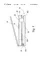
- FIG. 4is a perspective view of the first embodiment according to the present invention.
- FIG. 5is a cross-sectional view of sliding element of FIG. 2 .
- FIG. 6is a cross-sectional view of a sliding element with a damper.
- FIG. 7is a cross-sectional view of the second kind of embodiment, according to the present invention.
- FIG. 2shows a cross-sectional view of the first kind of embodiment image scanner 1 of the present invention.
- the image scanner 1comprises a housing 12 , a scanning plate 23 for holding a scanned object, sliding elements 50 pinching at the both sides 24 of the scanning plate 23 , a carriage 40 fixed on the sliding elements 50 , and a driving device 60 for driving the carriage 40 .
- the scanner 1further comprises a lid 10 for pressing the scanned object placed on the scanning plate 23 .
- the scanning plate 23has a smooth flat surface for holding a scanned object and is better to be made by glass material, but it can also be made by transparent materials like plastic.
- the sliding elements 50are able to move front and back along stretch-out edges 24 .
- the carriage 40is fixed on the sliding elements 50 , therefore the distance between the carriage 40 and the scanned object on scanning plate 23 is kept by the combination of stretch-out edges 24 and sliding elements 50 .
- the carriage 40is fixed on the sliding elements by screws, or by inserting the pins at carriage 40 into the holes at sliding elements 50 .
- FIG. 5shows a cross-sectional view of the sliding element 50 .
- the sliding element 50is shaped like “C” and the open 51 is pinched by the stretch-out edges 24 of scanning plate 23 .
- the carriage 40is fixed on those sliding elements 50 , those sliding elements 50 will not be separated from the scanning plate 23 .
- FIG. 6illustrates the second embodiment of sliding element 50 a .
- the sliding elements 50 ahas the same shape “C” and same contact elements 52 , 53 and 54 , and further has a flexible damper 55 (e.g. spring, flexible elements etc.) in one side.
- the damper 55is inserted between the side wall and the contact element 53 of sliding element 50 a .
- the contact element 53is against the side surface of scanning plate 23 , and by the spring force the contact element 53 absorbs the width tolerance of scanning plate 23 and reduces the torque while moving of carriage 40 .
- damper 53makes carriage 40 to keep away from floating at widthwise, which will damage the scanning quality when the scanner is working.
- FIG. 7illustrates a cross-sectional view of sliding element 50 a with damper 53 .
- Carriage 40is mounted on the undersides of sliding elements 50 and keeps a predefined distance from the scanning plate 23 . Because the carriage 40 is fixed at sliding elements 50 , the carriage 40 is moved by driving device 60 along the lengthwise direction of scanning plate 23 .
- the driving device 60includes motor 61 , gears set 62 , 63 , 64 , and rack 65 .
- the motor 61 and gears set 62 , 63 , 64are fixed on carriage 40 and the rack 65 is fixed on the housing 12 .
- the rack 65can also be a part of housing and is formed by plastic.
- the gear set 62 , 63 , 64are engaged with each other.
- the gear 62is engaged with the shaft of motor 61 and the gear 64 is engaged with the rack 65 .
- the motor 61When the scanner is scanning, the motor 61 is actuated to turn and drives the gears set 62 , 63 , and 64 . Because the gear 64 is engaged with the rack 65 , carriage 40 is moved while gear 64 is turning.
- driving device 60is not the only way for driving carriage 40 .
- Many variations and equivalentse.g. using step belt, loop driving device etc. to achieve the same result
- the sliding elementsare pinched at both side of the scanning plate and the carriage is fixed at sliding elements. Because the scanning plate is the reference base for both carriage and scanned object, there is no problem about the adjustment caused by the different reference bases of a scanned object and carriage in the prior art.
Landscapes
- Engineering & Computer Science (AREA)
- Multimedia (AREA)
- Signal Processing (AREA)
- Facsimile Scanning Arrangements (AREA)
- Optical Systems Of Projection Type Copiers (AREA)
Abstract
Description
Claims (8)
Priority Applications (1)
| Application Number | Priority Date | Filing Date | Title |
|---|---|---|---|
| US09/251,339US6373601B1 (en) | 1999-02-17 | 1999-02-17 | Image scanner |
Applications Claiming Priority (1)
| Application Number | Priority Date | Filing Date | Title |
|---|---|---|---|
| US09/251,339US6373601B1 (en) | 1999-02-17 | 1999-02-17 | Image scanner |
Publications (1)
| Publication Number | Publication Date |
|---|---|
| US6373601B1true US6373601B1 (en) | 2002-04-16 |
Family
ID=22951525
Family Applications (1)
| Application Number | Title | Priority Date | Filing Date |
|---|---|---|---|
| US09/251,339Expired - LifetimeUS6373601B1 (en) | 1999-02-17 | 1999-02-17 | Image scanner |
Country Status (1)
| Country | Link |
|---|---|
| US (1) | US6373601B1 (en) |
Cited By (6)
| Publication number | Priority date | Publication date | Assignee | Title |
|---|---|---|---|---|
| US20020054361A1 (en)* | 2000-07-19 | 2002-05-09 | Naho Saito | Image reading apparatus |
| US20030112478A1 (en)* | 2001-12-19 | 2003-06-19 | Martin Chang | Scanning module having an adjustable height |
| US20040105133A1 (en)* | 2002-10-01 | 2004-06-03 | Canon Kabushiki Kaisha | Image reading apparatus |
| US20050151762A1 (en)* | 2004-01-14 | 2005-07-14 | Griesemer Frederick C. | Image recording apparatus with slidably opening scanner bed |
| US20060158965A1 (en)* | 2005-01-20 | 2006-07-20 | Benq Corporation | Gear train module and electronic device utilizing the same |
| JP2012090007A (en)* | 2010-10-18 | 2012-05-10 | Seiko Epson Corp | Image reading device and image reading method |
Citations (4)
| Publication number | Priority date | Publication date | Assignee | Title |
|---|---|---|---|---|
| US5717982A (en)* | 1997-02-27 | 1998-02-10 | Xerox Corporation | Electrostatographic reproduction machine including optics assembly realignment tool |
| US5844695A (en)* | 1995-12-07 | 1998-12-01 | Canon Kabushiki Kaisha | Image reading system |
| US6169611B1 (en)* | 1997-12-24 | 2001-01-02 | Agfa Corporation | Mounting system for a removable media holder in a scanning apparatus |
| US6250731B1 (en)* | 1996-03-14 | 2001-06-26 | Canon Kabushiki Kaisha | Printing apparatus with displaceable carriage guiding member |
- 1999
- 1999-02-17USUS09/251,339patent/US6373601B1/ennot_activeExpired - Lifetime
Patent Citations (4)
| Publication number | Priority date | Publication date | Assignee | Title |
|---|---|---|---|---|
| US5844695A (en)* | 1995-12-07 | 1998-12-01 | Canon Kabushiki Kaisha | Image reading system |
| US6250731B1 (en)* | 1996-03-14 | 2001-06-26 | Canon Kabushiki Kaisha | Printing apparatus with displaceable carriage guiding member |
| US5717982A (en)* | 1997-02-27 | 1998-02-10 | Xerox Corporation | Electrostatographic reproduction machine including optics assembly realignment tool |
| US6169611B1 (en)* | 1997-12-24 | 2001-01-02 | Agfa Corporation | Mounting system for a removable media holder in a scanning apparatus |
Cited By (9)
| Publication number | Priority date | Publication date | Assignee | Title |
|---|---|---|---|---|
| US20020054361A1 (en)* | 2000-07-19 | 2002-05-09 | Naho Saito | Image reading apparatus |
| US6975436B2 (en)* | 2000-07-19 | 2005-12-13 | Canon Kabushiki Kaisha | Image reading apparatus |
| US20030112478A1 (en)* | 2001-12-19 | 2003-06-19 | Martin Chang | Scanning module having an adjustable height |
| US7170649B2 (en)* | 2001-12-19 | 2007-01-30 | Avision Inc. | Scanning module having an adjustable height |
| US20040105133A1 (en)* | 2002-10-01 | 2004-06-03 | Canon Kabushiki Kaisha | Image reading apparatus |
| US7847983B2 (en)* | 2002-10-01 | 2010-12-07 | Canon Kabushiki Kaisha | Image reading apparatus |
| US20050151762A1 (en)* | 2004-01-14 | 2005-07-14 | Griesemer Frederick C. | Image recording apparatus with slidably opening scanner bed |
| US20060158965A1 (en)* | 2005-01-20 | 2006-07-20 | Benq Corporation | Gear train module and electronic device utilizing the same |
| JP2012090007A (en)* | 2010-10-18 | 2012-05-10 | Seiko Epson Corp | Image reading device and image reading method |
Similar Documents
| Publication | Publication Date | Title |
|---|---|---|
| US8289587B2 (en) | Image reading apparatus | |
| US7557967B2 (en) | Image reading apparatus | |
| EP1309168A2 (en) | Structure for preventing extraneous light from entering image reading apparatus | |
| US4486786A (en) | Original reading device | |
| CN101552857B (en) | Image reading devices | |
| US6373601B1 (en) | Image scanner | |
| EP1650949B1 (en) | Original reading unit, image forming apparatus and image scanner | |
| EP1104623B1 (en) | Method and apparatus for keeping a document in focus during noncontact scanning | |
| GB2405284A (en) | Optical image scanner with adjustable image plane | |
| US4605971A (en) | Document reading device | |
| US6304358B1 (en) | Reflective/transmissive scanner with synchronously moving image sensor and light source | |
| US6064052A (en) | Image scanner | |
| US7880939B2 (en) | Film holder and flatbed type image scanner | |
| US7936486B2 (en) | Transferring guide device usable with image reading sensor unit and scanning apparatus having the same | |
| US7403306B2 (en) | Image reading with high fit accuracy | |
| US5452120A (en) | Lamp shade moving mechanism for transparency scannings | |
| US7158737B2 (en) | Carriage structure for image-reading device | |
| JPH03276958A (en) | Image scanner | |
| US20030117610A1 (en) | Film holder | |
| US20050133599A1 (en) | Image capture apparatus | |
| GB2326045A (en) | Document window movement transmission system for an optical scanner | |
| JP2976902B2 (en) | Document reading device | |
| JP4821191B2 (en) | Film holder and image reading apparatus | |
| US7242504B2 (en) | Optical scanning apparatus | |
| KR100528648B1 (en) | Driving device for the optical unit in image system |
Legal Events
| Date | Code | Title | Description |
|---|---|---|---|
| AS | Assignment | Owner name:MICROTEK INTERNATIONAL INC., TAIWAN Free format text:ASSIGNMENT OF ASSIGNORS INTEREST;ASSIGNOR:CHENG, LONG-SONG;REEL/FRAME:009789/0167 Effective date:19990208 | |
| STCF | Information on status: patent grant | Free format text:PATENTED CASE | |
| FEPP | Fee payment procedure | Free format text:PAYOR NUMBER ASSIGNED (ORIGINAL EVENT CODE: ASPN); ENTITY STATUS OF PATENT OWNER: SMALL ENTITY | |
| FPAY | Fee payment | Year of fee payment:4 | |
| FEPP | Fee payment procedure | Free format text:PAYER NUMBER DE-ASSIGNED (ORIGINAL EVENT CODE: RMPN); ENTITY STATUS OF PATENT OWNER: SMALL ENTITY Free format text:PAYOR NUMBER ASSIGNED (ORIGINAL EVENT CODE: ASPN); ENTITY STATUS OF PATENT OWNER: SMALL ENTITY Free format text:PAT HOLDER CLAIMS SMALL ENTITY STATUS, ENTITY STATUS SET TO SMALL (ORIGINAL EVENT CODE: LTOS); ENTITY STATUS OF PATENT OWNER: SMALL ENTITY | |
| FPAY | Fee payment | Year of fee payment:8 | |
| FPAY | Fee payment | Year of fee payment:12 |