US6373475B1 - Converter for resistive touchscreens - Google Patents
Converter for resistive touchscreensDownload PDFInfo
- Publication number
- US6373475B1 US6373475B1US09/403,563US40356300AUS6373475B1US 6373475 B1US6373475 B1US 6373475B1US 40356300 AUS40356300 AUS 40356300AUS 6373475 B1US6373475 B1US 6373475B1
- Authority
- US
- United States
- Prior art keywords
- controller
- contacts
- wire
- sensor
- converter according
- Prior art date
- Legal status (The legal status is an assumption and is not a legal conclusion. Google has not performed a legal analysis and makes no representation as to the accuracy of the status listed.)
- Expired - Fee Related
Links
Images


Classifications
- G—PHYSICS
- G06—COMPUTING OR CALCULATING; COUNTING
- G06F—ELECTRIC DIGITAL DATA PROCESSING
- G06F3/00—Input arrangements for transferring data to be processed into a form capable of being handled by the computer; Output arrangements for transferring data from processing unit to output unit, e.g. interface arrangements
- G06F3/01—Input arrangements or combined input and output arrangements for interaction between user and computer
- G06F3/03—Arrangements for converting the position or the displacement of a member into a coded form
- G06F3/041—Digitisers, e.g. for touch screens or touch pads, characterised by the transducing means
- G06F3/045—Digitisers, e.g. for touch screens or touch pads, characterised by the transducing means using resistive elements, e.g. a single continuous surface or two parallel surfaces put in contact
Definitions
- An electrographic sensoris a device for determining the co-ordinates of an event, generally in a two-dimensional system, or for inputting such co-ordinates into, for example, a computer.
- Such devices in the form of touchscreenshave become widely used for inputting information into computers, as a means of operating cash dispensers, sales tills, ticketing machines, computer games and medical and industrial instrumentation. They have many advantages including speed and ease of use, small size, reliability, and accuracy.
- a touchscreenwill usually be used in conjunction with some form of display such as a cathode ray tube or a liquid crystal screen.
- the touchscreenis placed over such a display and can indicate to a computer controlling the display which icon or other element of the display has been selected by the user.
- touchscreensmay make use of capacitance, surface acoustic waves, or resistance. It is with the last of these possibilities that I am now concerned.
- Resistive touchscreensemploy transparent layers of a resistive material which come into contact with one another when the screen is touched. This contact completes a circuit, the resistance of which depending on the position where the contact was made. As a result, the magnitude of the output from the touchscreen will depend on the position of the touch.
- Touchscreensthemselves are used in conjunction with a controller which applies the desired voltages to the various resistive layers, and also passes the output of the screen, generally after digitising it, to the computer or other device to be controlled.
- a controllerwhich applies the desired voltages to the various resistive layers, and also passes the output of the screen, generally after digitising it, to the computer or other device to be controlled.
- a four-wire screenconsists of two transparent, resistive layers separated by a grid of minute dots.
- the lower layermay be rigid, but the upper layer will be flexible so that when the screen is touched the two layers come into contact between adjacent dots where the screen is touched.
- the lower layermay be provided with electrodes running along its left and right edges (for example). When a potential difference is applied between those electrodes a voltage gradient will be produced from left to right. A voltage picked up by contacting this layer will therefore have a magnitude that depends on the position of contact. In this example the voltage gradient extends from left to right and therefore the voltage picked up will provide an X-co-ordinate of position.
- the upper layerwill have electrodes along its top and bottom edges (picture the layers in the vertical plane in front of you), and analogously a voltage difference applied between those electrodes will give rise to an output whose magnitude depends on the Y-co-ordinate of the position of touch.
- the circuitsare completed as follows. When the X-co-ordinate is being measured the left-hand electrode on the lower layer is connected to ground, the right-hand, electrode on the lower layer is connect to (say) 5 V, and the two electrodes of the upper layer are connected together. The voltage between those two electrodes and ground is then measured. When the screen is touched a voltage will be produced that is somewhere between 0 V and 5 V, depending on the X-co-ordinate of the position of touch. It will be appreciated that the voltage will be independent of the Y-co-ordinate of the touch.
- the connectionsare now altered in order to measure the Y-co-ordinate.
- the left and right-hand electrodes of the lower layerare now connected together, and a potential difference is applied between the two electrodes of the top layer.
- the outputwill of course be the voltage appearing at the combined electrodes of the bottom layer.
- the device that applies these voltages and that measures the output voltage when the screen is touchedis the so-called controller that was referred to above.
- the controllerhas a further function, namely touch detection. It can be seen that power is consumed continuously while the screen and controller are in the above X-measurement and Y-measurement states. In the X-measurement state, for example, a potential difference is maintained across the lower layer and current will flow whether or not the screen is being touched. The waste of power is considerable since for most of the time the screen will not be being touched. In the touch detection state the controller applies, say, 5 V to both the left and right electrodes on the bottom layer, and connects together the two electrodes of the top layer. No current will flow since there is no potential difference across either of the layers. When the screen is touched the controller detects a voltage at the combined electrodes of the top layer.
- controllerThis causes the controller to re-organise its connections to the screen to apply a potential difference between the left and right electrodes on the bottom layer and make the X-measurement as described above. Once this is done the controller re-organises the connections again to apply a potential difference between the electrodes on the top layer to make the Y-measurement. It may repeat these two measurements one or more times to avoid spurious readings, and then it will return to the touch detection state and await a further touch.
- the voltage measurementsmay be made in any suitable way, but generally an analogue-digital converter (ADC) will be used to produce a digitalized output to be fed to the computer to be controlled by the touchscreen.
- ADCanalogue-digital converter
- a five-wire touchscreenoperates in a different, and apparently incompatible, way to that described above.
- the five wiresare connected in the following way. Four of them are connected to the four comers of the lower electrode and the fifth wire is connected to an arbitrary position on the upper electrode.
- the four wires to the bottom electrodeare connect to, say, 5 V.
- Detection of a voltage at the top layerindicates that the screen has been touched.
- Thisthen causes the five-wire controller to switch to its X-measurement state as follows. In this state the top and bottom left-hand comers (again imagine the layer in the vertical plane in front of you) are connected to ground, and the top and bottom right-hand corners are connected to, say, 5 V.
- the controller and screen switchto the Y-measurement state where the top left and top right corners are connected to, say, 5 V and the bottom left and right corners are connected to ground. Now the voltage on the top layer will give an indication of the Y-co-ordinate of a touch on the screen.
- the present inventionprovides a converter for connection between an electrographic sensor and an electrographic controller, and comprising:
- the emulatormay additionally emulate at the second contacts:
- the converterwill be fully universal, in that either type of sensor may be connected to either type of controller. I prefer that the converter be able automatically to determine which type of sensor and which type of controller are connected to it.
- the convertermay additionally comprise:
- a first devicethat can determine which of a four- and five-wire sensor is connected to the first set of contacts and/or which of a four- and five-wire controller is connected to the second set of contacts; and which can, at least in part from such determination, cause the emulator to effect an appropriate emulation.
- the convertermay comprise:
- a second devicethat can determine which of a sensor and a controller is connected to one of the sets of contacts; and which can, at least in part from such determination, cause the emulator to effect an appropriate emulation.
- controllermay be provided with two sets of five contacts for example in the form of five-pin plugs and/or five-pin sockets.
- the emulation carried out by the convertermay consist simply in forming appropriate (direct or indirect) interconnections between the first set of contacts and the second set of contacts. However, in some cases it may be preferred that the emulation consist in reading a signal at a contact of one of the first and second sets of contacts and then writing an appropriate signal to a contact of the other of the first and second sets. This second possibility might be desirable where the sensor requires different voltages or source impedances etc, in addition to different patterns of interconnection, from that provided by the controller.
- an electrographic controllerpasses through several different states, namely touch detection, X-measurement and Y-measurement.
- the converter of the inventionwill have first, second and third states corresponding to these states of the sensor and controller.
- a separate convertercould be provided for each state and the controller could switch between them.
- the converteris preferably controlled by the controller and simply follows the changes that occur in the controller. I prefer that the emulator be caused to switch between its states by signals from the controller at the second set of contacts.
- the standard output(which in the absence of the controller of the invention would be connected directly to the sensor) provides all the information necessary for the controller to change states.
- An alternativewould be to provide some additional connection between controller and converter but this is not at present preferred.
- the standard output from the controllerpreferably also provides all the power necessary for the emulator to effect the appropriate emulation and switching between states. I also prefer that the standard output provide any voltage references needed.
- the emulatorpreferably has switches whose states constitute the state of the emulator, the normal states (ie those states which result from the absence of any applied power and/or the dissipation of any charge) of those switches corresponding to the first, ie touch detection state, of the emulator.
- (iv)causes the emulator to adopt first, second and third states appropriate to the type of sensor and the type of controller connected and according to the state from time to time adopted by the controller.
- the controllerneed not be fully universal in this sense. For example, it could have separate sets of contacts dedicated to the type of equipment to be connected, or it could have switches or other means of control to be operated by the user depending on the type of equipment that is connected.
- the controllermakes the above determinations automatically, a variety of techniques may be used which, in the light of the present specification, the skilled reader will be readily able to devise. For example, the controller may be able to determine whether a sensor or a controller is connected to a given set of contacts by determining whether a voltage exists between any contacts of that set. If a voltage is detected the equipment will be a controller.
- Measurement of the resistance between pairs of contacts to which a sensor is detectedwill determine whether the sensor is a four-wire sensor or a five-wire sensor. Also, a four-wire controller may be distinguished from a five-wire controller by determining voltages between pairs of said contacts.
- the controller of the inventionmay be provided as a separate or free-standing, piece of equipment or it maybe pre-connected to or part of a sensor or pre-connected to or part of a controller.
- FIG. 1shows a prior art five-wire touchscreen connected to a five-wire controller
- FIG. 2shows a four-wire touchscreen connected to a four-wire controller
- FIGS. 3 a , 3 b and 3 cshow three states of a five-wire controller
- FIGS. 4 a , 4 b and 4 cshow three states of a four-wire controller
- FIG. 5shows a converter of the invention connected between a touchscreen and a controller
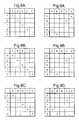
- FIGS. 6 a , 6 b and 6 cshow three states of a controller for connection between a five-wire screen and a four-wire controller
- FIGS. 7 a , 7 b and 7 cshow three states of a controller for connection between a four-wire screen and a five-wire controller
- FIGS. 8 a , 8 b and 8 cshow three states of a controller for connection between a five-wire screen and a five-wire controller
- FIGS. 9 a , 9 b and 9 cshow three states of a controller for connection between a four-wire screen and a four-wire controller
- FIG. 10is a circuit diagram of a preferred controller.
- FIG. 11shows such a controller connected between a five-wire screen and a four-wire controller.
- the touchscreen shown in exploded form in FIG. 1is taken from U.S. Pat. No. 4,661,655.
- a touchscreen 1is connected by various conductors to a controller 2 .
- the screenis shown in exploded form and its vertical dimensions are greatly exaggerated.
- a uniform resistive surface 3is applied to a suitable substrate 4 .
- the substratemay be planar (as shown), or contoured to match the face of a curved object such as a conventional video display screen.
- An opaque sensormay be produced using for example resistive inks as the resistive coating which may typically have a sheet resistivity between 10 and 10,000 ohms per square. More usually, however, the resistive coating and substrate will be substantially transparent in order that the sensor be usable as a touchscreen.
- the resistive layeris typically a semiconducting metal oxide such as indium tin oxide. Again typical resistivities lie between 10 and 10,000 ohms per square. Further details of such resistive coatings may be found in U.S. Pat. No. 4,220,815, the disclosure of which is incorporated herein by reference.
- a contact or pickoff sheettypically comprising a flexible film 5 having a conductive coating 6 on its underneath surface.
- the conductive coatingmust also be transparent.
- the flexible film 5may comprise a plastic such as polyester or polycarbonate, or it may be elastomeric.
- the conductive coating 6should have a similar flexibility to that of the flexible film, and its resistivity is typically less than 1,000 ohms per square.
- the separating meanscomprises a plurality of minute dots 7 of insulating material, some of which are shown in the figure. Such dots and other insulating means are disclosed in U.S. Pat. No. 4,220,815 and U.S. Pat. No. 3,798,370, the disclosures of which are incorporated herein by reference.
- a resistor element 8Spaced along each edge of the resistive coating 3 , but insulated therefrom, is a resistor element 8 used to apply voltages to the resistive layer.
- This resistor elementmay be continuous, as shown, or in the form of discrete units connected in series.
- the resistor elementmay comprise four components, one along each edge, joined at the comers of the screen. At each comer an electrical lead 9 is provided for connection of the screen to the controller 2 .
- U.S. Pat. No. 4,661,655discloses a plurality of electrodes 10 along selected paths adjacent each edge of the resistive coating 3 and in contact therewith. These electrodes 10 are provided so as to achieve varying effective voltage gradients in the resistive coating 3 to compensate for the voltage drop along the resistive element 8 . Accordingly, the effective voltage gradients in the coating 3 decrease progressively from corners of the screen towards the centre of each path as the voltage drop increases along the resistive element 8 . These effects, voltage gradient and voltage drop, are made to balance one another to make the voltage gradients rectilinear.
- the screenalso includes an electrode 11 for connection of the upper resistive layer 6 to the controller 2 .
- the upper film 5 and resistive layer 6may be joined to the lower layers through an insulating adhesive frame 12 .
- the controller 2has means 13 for connecting it to a power supply 13 and has a digital or other output 14 for connection to a computer or other device that is to process the positional information obtained from the touchscreen. That digital output may be obtained from an analogue-digital converter (ADC) within the controller 2 that digitizes a voltage measured across a high impedance 15 connected between the upper resistive layer 6 and ground.
- ADCanalogue-digital converter
- FIG. 2shows a four-wire screen 1 connected to a four-wire controller 2 .
- the lower resistive layer 3has simple bussing electrodes 16 , 17 at its left and right-hand edges.
- the upper resistive layer 6has bussing electrodes 18 and 19 at its bottom and top edges respectively (as drawn).
- FIGS. 3 a , 3 b and 3 cshow three states of the five-wire controller of FIG. 1 .
- the state shown in FIG. 3 ais the touch detection state.
- contacts A, B, C and Dare provided with 5 volts and contact E is connected to the ADC which provides an output to the computer. These five contacts are connected to the screen as shown in FIG. 1 .
- a 0 volt referencemay be taken from the ADC or provided separately.
- a contactis made between the lower resistive layer 3 and the upper resistive layer 6 which causes a voltage to appear at contact E which is detected by the ADC and causes the computer to switch the controller to the second state, that is illustrated in FIG. 3 b .
- This stateis for measurement of the X-co-ordinate of the position of the touch of the screen. In-this state contacts A and D are connected to 0 volts and contacts B and D are connected to 5 volts. Contact E remains connected to the ADC. It can be seen that in this state a potential gradient exists across the resistive layer 3 from left to right as drawn in FIG. 1 .
- the value of the voltage detected by the ADCwill be a function of the X-co-ordinate of the position of touch.
- the controllerswitches to its third state, namely that shown in FIG. 3 c .
- contacts A and Bare provided with 5 volts and contacts C and D are provided with 0 volts.
- contact Eremains connected to the ADC.
- the controllermakes several X and Y-measurements before returning to the touch detection state. This ensures that spurious determinations of position are not made, particularly where the position of touch is rapidly altered.
- FIGS. 4 a , 4 b and 4 care analogous to FIGS. 3 a , 3 b and 3 c , but show the states of a four-wire controller.
- the five-wire screen of FIG. 1may be used with the four-wire controller of FIG. 2 and/or the four-wire screen of FIG. 2 may be used with the five-wire controller of FIG. 1 .
- FIG. 5shows a touchscreen 20 connected to a controller 21 via a converter 22 of the invention.
- the converter 22is shown having a plug or socket 23 for connection to the screen and a plug or socket 24 for connection to the controller.
- Each of these plugs or socketsis preferably provided with five contacts in order that the converter be fully universal. Whether or not the fifth contact is used will, of course, depend on whether the screen and/or the controller are of the five-wire or of the four-wire designs.
- the fifth connectionis shown as a dotted line in each case.
- the whole systemis preferably powered through the controller 21 , and for this purpose a means 13 for connecting to a source of power is shown.
- the converter 22may have its own source of power.
- FIGS. 6, 7 , 8 and 9are state diagrams illustrating the function of the converter depending on the type of screen, the type of controller and the state of the controller.
- the converteris used to connect a five-wire screen to a four-wire controller.
- FIG. 6 ashows connections that the controller makes between the contacts A, B, C, D, E of a four-wire controller to the contacts P, Q, R, S, T of a five-wire screen.
- the dotsindicate where connections are made.
- Such a state diagrammay also be used to indicate the state of a converter that reads signals from one set of contacts and writes appropriate signals to the other set of contacts.
- the diagramindicates that a connection is made between contact P of the screen (the top left-hand corner of the screen in FIG. 1) and contact D of the controller shown in FIG. 2, the touch detection state of which being shown in FIG. 4 a .
- the diagramcould represent that the signal at contact D (which FIG.
- FIG. 6 bshows the pattern of interconnections or read and write arrangements that the converter adopts when the X-co-ordinate is to be measured.
- the controlleris in the state indicated in FIG. 4 b .
- FIG. 6 cis the state diagram appropriate to measurement of the Y-co-ordinate, when the controller will be in the state indicated in FIG. 4 c.
- FIGS. 7 a , 7 b and 7 ccorrespond to FIGS. 6 a , 6 b and 6 c , but here a four-wire screen is connected to a five-wire controller.
- FIGS. 8 a , 8 b and 8 cshow the trivial states required of a converter connected between a five-wire screen and a five-wire controller.
- FIG. 9 a , 9 b and 9 cdoes the same thing for a converter connected between a four-wire screen and a four-wire controller.
- the converterreceive all its information from the controller through the contacts A, B, C, D and E.
- the controllerwould then monitor, for example, the voltages on these contacts, and set its own state accordingly. For example, if a converter positioned between a five-wire screen and a four-wire controller detected 5 volts on two of pins A, B, C, D and E and no voltages on the other three pins, then it would know that the controller was in the touch detection state (compare FIGS. 4 a , 4 b and a c ), and it would set its state to that shown in FIG. 6 a . Clearly if the controller has been told which of contacts A, B, C, D and E are which, they the investigation that it needs to make is reduced.
- My preferred converterwill therefore constantly monitor the state of the contacts connected to the controller and will automatically alter its state to provide the emulation required. It is of course desirable that the converter be capable of switching between its states faster than the controller switches between its states.
- the controllerprovides the converter with a signal instructing it to alter its state that is independent of the standard contacts A, B, C, D and E intended for controlling the screen.
- FIG. 10shows a preferred converter circuit that uses a state machine to provide the desired variety of interconnections between controller and screen, and also to power the screen.
- the converterconnects a five-wire screen to a four-wire controller, but an analogous circuit could be used for other arrangements.
- the state machineis code which resides in a PIC16C54 microcontroller.
- a four channel single-pole-single-throw (SPST) analogue switchis controlled by the microcontroller. This switches the upper resistive layer (layer 6 of FIG. 1) to the appropriate contact of contacts A, B, C and D of the controller (see FIG. 2 and FIGS. 4 a , 4 b and a c .).
- SPSTsingle-pole-single-throw
- the converterresponds to this state by applying 5 volts to the four corners P, Q, R, S of the screen, and uses the analogue switches to connect the upper resistive layer to contacts A and B of the controller.
- the controllercycles through a sequence of X and Y-measurements, interspersed with touch detection checks.
- An X-co-ordinate measurementbegins when the controller sets contact C to 5 volts and contact D to 0 volts.
- the converterdetects this state and places 5 volts on comers Q and R of the five-wire screen, 0 volts on corners P and S, and at the same time switches the upper resistive layer 6 to contacts A and B.
- a Y-co-ordinate measurementbegins when the controller sets contacts B to 5 volts and contact A to 0 volts. The converter then detects this state and places 5 volts on comers P and Q of the screen, and 0 volts on comers S and R, and at the same time switches the upper resistive layer to contact C and D.
- FIG. 2shows the touch screen, the four-wire controller and the converter.
- the converteris powered by an external low current 5 volts supply, although as mentioned above power could be derived from the standard contacts of the controller.
- This latter arrangementis preferred for a number of reasons, in particular it allows the converter to be constructed in the housing of the screen itself, or in a connector therefor, and avoids the need for further interconnections.
Landscapes
- Engineering & Computer Science (AREA)
- General Engineering & Computer Science (AREA)
- Theoretical Computer Science (AREA)
- Human Computer Interaction (AREA)
- Physics & Mathematics (AREA)
- General Physics & Mathematics (AREA)
- Electronic Switches (AREA)
- Position Input By Displaying (AREA)
- Details Of Connecting Devices For Male And Female Coupling (AREA)
- Testing Of Short-Circuits, Discontinuities, Leakage, Or Incorrect Line Connections (AREA)
- Control Of Position, Course, Altitude, Or Attitude Of Moving Bodies (AREA)
Abstract
Description
| INDADD | EQU 0 | ;INDIRECT ADRESSING | |
| REGISTER | |||
| RTCC | EQU 1 | ;COUNTER | |
| PC | EQU 2 | ;PROGRAM COUNTER | |
| STATUS | EQU 3 | ;STATUS REGISTER | |
| FSR | EQU 4 | ;FILE SELECT REGISTER | |
| PORTA | EQU 5 | ;PORT A | |
| PORTB | EQU 6 | ;PORT B | |
| GEN | EQU 7 | ;PORT C NOT USED, | |
| SO GENERAL PURPOSE | |||
| REG | |||
| CARRY | EQU 0 | ;BIT 0 IS CARRY | |
| DCARRY | EQU 1 | ;BIT 1 IS DIGIT CARRY | |
| Z | EQU 2 | ;BIT 2 IS ZERO BIT | |
| PDOWN | EQU 3 | ;BIT 3 IS POWER DOWN BIT | |
| WATCHD | EQU 4 | ;BIT 4 IS WATCH DOG | |
| TIMEOUT BIT | |||
| W | EQU 0 | ;RESULT DESTINATION TO | |
| W REGISTER | |||
| F | EQU 1 | ;RESULT DESTINATION TO | |
| F REGISTER | |||
| BIT0 | EQU 0 | ||
| BIT1 | EQU 1 | ||
| BIT2 | EQU 2 | ||
| BIT3 | EQU 3 | ||
| BIT4 | EQU 4 | ||
| BIT5 | EQU 5 | ||
| BIT6 | EQU 6 | ||
| BIT7 | EQU 7 | ||
| ORG 00H | |||
| START | movlw | #00H | |
| tris | PORTB | ;Port B is eight bit output port | |
| movlw | #0FH | ;Port A is four bit input port | |
| tris | PORTA | ||
| goto | MAIN | ||
| MAIN | clrwdt | ||
| movlw | #00H | ;All outputs off initially | |
| movwf | PORTB | ||
| nop | ;timing delay | ||
| nop | |||
| nop | |||
| nop | |||
| nop | |||
| nop | |||
| nop | |||
| nop | |||
| nop | |||
| nop | |||
| AGAIN | clrwdt | ||
| mowf | PORTA, W | ;Read input port | |
| andlw | #0CH | ;Mask off upper 2 bits of nybble | |
| xorlw | #0CH | ;Check for touch detection | |
| btfsc | STATUS, Z | ||
| goto | TOUCH | ;Call touch detection code | |
| goto | AGAIN | ||
| XM | movlw | #31H | ;output code for X measurement |
| movlw | PORTB | ||
| nop | ;Timing delay | ||
| nop | |||
| nop | |||
| nop | |||
| nop | |||
| nop | |||
| nop | |||
| nop | |||
| nop | |||
| nop | |||
| XLOOP | clrwt | ;Reset WDT | |
| movf | PORTA, W | ;Read input port | |
| andlw | #0CH | ;Mask off all bits except 2 | |
| msb of nybble | |||
| xorlw | #08H | ;Detect y measurement | |
| btfsc | STATUS, Z | ||
| goto | YM | ;Call y measurement code | |
| movf | PORTA, W | ;Read input port | |
| andlw | #0H | ;Check for touch detection | |
| btfsc | STATUS, Z | ||
| goto | TOUCH | ;Call touch detection code | |
| goto | XLOOP | ;continue looking for | |
| y measurement | |||
| phase | |||
| YM | movlw | #2AH | ;output code for Y measurement |
| movwf | PORTB | ||
| nop | |||
| nop | |||
| nop | |||
| nop | |||
| nop | |||
| nop | |||
| nop | |||
| nop | |||
| nop | |||
| nop | |||
| YLOOP | clrwdt | ||
| movf | PORTA, W | ;Read input port | |
| andlw | #0CH | ;Mask off upper 2 bits of nybble | |
| xorlw | #0CH | ;Check for touch detection | |
| btfsc | STATUS, Z | ||
| goto | TOUCH | ;Call touch detection code | |
| movf | PORTA, W | ;Read input port | |
| andlw | #03H | ;Mask off all bits except 2 lsb | |
| xlorlw | #01H | ;Detect x measurement | |
| btfsc | STATUS, Z | ||
| goto | XM | ;Call x measurement code | |
| goto | YLOOP | ;look for touch detection phase | |
| TOUCH | movlw | #3EH | ;output code for touch detection |
| movwf | PORTB | ||
| nop | ;Timing delay | ||
| nop | |||
| nop | |||
| nop | |||
| nop | |||
| nop | |||
| nop | |||
| nop | |||
| nop | |||
| nop | |||
| nop | |||
| nop | |||
| nop | |||
| nop | |||
| nop | |||
| nop | |||
| nop | |||
| nop | |||
| nop | |||
| nop | |||
| nop | |||
| nop | |||
| TLOOP | clrwdt | ;Reset WDT | |
| movf | PORTA, W | ;Read input port | |
| andlw | #03H | :Mask off all bits except 2 lsb | |
| xorlw | #01H | ;Detect x measurement | |
| btfsc | STATUS, Z | ||
| goto | XM | ;Call x measurement code | |
| movf | PORTA, W | ;Read input port | |
| andlw | #0CH | ;Mask off all bits except 2 | |
| msb of nybble | |||
| xorlw | #08H | ;Detect y measurement | |
| btfsc | STATUS, Z | ||
| goto | YM | ; Call y measurement code | |
| goto | TLOOP | ;continue looking for | |
| x measurement | |||
| ORG 01FFH | |||
| RESET | goto | START | ;Reset vector back to start |
| of code. | |||
| END | |||
Claims (18)
Applications Claiming Priority (3)
| Application Number | Priority Date | Filing Date | Title |
|---|---|---|---|
| GBGB9708464.4AGB9708464D0 (en) | 1997-04-25 | 1997-04-25 | Converter for resistive touchscreens |
| GB9708464 | 1997-04-25 | ||
| PCT/GB1998/001094WO1998049650A1 (en) | 1997-04-25 | 1998-04-15 | Converter for resistive touchscreens |
Publications (1)
| Publication Number | Publication Date |
|---|---|
| US6373475B1true US6373475B1 (en) | 2002-04-16 |
Family
ID=10811396
Family Applications (1)
| Application Number | Title | Priority Date | Filing Date |
|---|---|---|---|
| US09/403,563Expired - Fee RelatedUS6373475B1 (en) | 1997-04-25 | 1998-04-15 | Converter for resistive touchscreens |
Country Status (9)
| Country | Link |
|---|---|
| US (1) | US6373475B1 (en) |
| EP (1) | EP0976096B1 (en) |
| JP (1) | JP2001522493A (en) |
| AU (1) | AU7060898A (en) |
| CA (1) | CA2287351C (en) |
| DE (1) | DE69804204T2 (en) |
| GB (1) | GB9708464D0 (en) |
| TW (1) | TW455807B (en) |
| WO (1) | WO1998049650A1 (en) |
Cited By (29)
| Publication number | Priority date | Publication date | Assignee | Title |
|---|---|---|---|---|
| US20020097228A1 (en)* | 2001-01-23 | 2002-07-25 | Mobigence, Inc. | Expanded touch panel display |
| US6593916B1 (en)* | 2000-11-03 | 2003-07-15 | James L. Aroyan | Touchscreen having multiple parallel connections to each electrode in a series resistor chain on the periphery of the touch area |
| US6611257B1 (en)* | 2000-09-29 | 2003-08-26 | Rockwell Automation Technologies, Inc. | Automatic detection of touch plane type |
| US6661408B2 (en)* | 2001-03-23 | 2003-12-09 | Eturbotouch Technology Inc. | Touch screen capable of isolating noise signals |
| US6753853B1 (en)* | 2000-09-29 | 2004-06-22 | Rockwell Automation Technologies, Inc. | Low power dissipation touch plane interface circuit |
| US6765558B1 (en)* | 2000-09-29 | 2004-07-20 | Rockwell Automation Technologies, Inc. | Multiple touch plane compatible interface circuit and method |
| WO2005091322A1 (en)* | 2004-03-18 | 2005-09-29 | Eleksen Limited | Sensor assembly |
| US6980201B1 (en) | 2000-09-29 | 2005-12-27 | Rockwell Automation Technologies, Inc. | Minimum move touch plane scanning method and device |
| US20070229477A1 (en)* | 1998-05-15 | 2007-10-04 | Ludwig Lester F | High parameter-count touchpad controller |
| US20090153497A1 (en)* | 2007-12-14 | 2009-06-18 | Samsung Electronics Co., Ltd. | User interface device and input element |
| US20090254869A1 (en)* | 2008-04-06 | 2009-10-08 | Ludwig Lester F | Multi-parameter extraction algorithms for tactile images from user interface tactile sensor arrays |
| US20100044121A1 (en)* | 2008-08-15 | 2010-02-25 | Simon Steven H | Sensors, algorithms and applications for a high dimensional touchpad |
| US20100073486A1 (en)* | 2008-09-24 | 2010-03-25 | Huei Chuan Tai | Multi-dimensional input apparatus |
| US20110055722A1 (en)* | 2009-09-02 | 2011-03-03 | Ludwig Lester F | Data Visualization Environment with DataFlow Processing, Web, Collaboration, Advanced User Interfaces, and Spreadsheet Visualization |
| US20110066933A1 (en)* | 2009-09-02 | 2011-03-17 | Ludwig Lester F | Value-driven visualization primitives for spreadsheets, tabular data, and advanced spreadsheet visualization |
| US20110202889A1 (en)* | 2010-02-12 | 2011-08-18 | Ludwig Lester F | Enhanced roll-over, button, menu, slider, and hyperlink environments for high dimensional touchpad (htpd), other advanced touch user interfaces, and advanced mice |
| US8477111B2 (en) | 2008-07-12 | 2013-07-02 | Lester F. Ludwig | Advanced touch control of interactive immersive imaging applications via finger angle using a high dimensional touchpad (HDTP) touch user interface |
| US8509542B2 (en) | 2009-03-14 | 2013-08-13 | Lester F. Ludwig | High-performance closed-form single-scan calculation of oblong-shape rotation angles from binary images of arbitrary size and location using running sums |
| US8702513B2 (en) | 2008-07-12 | 2014-04-22 | Lester F. Ludwig | Control of the operating system on a computing device via finger angle using a high dimensional touchpad (HDTP) touch user interface |
| US8754862B2 (en) | 2010-07-11 | 2014-06-17 | Lester F. Ludwig | Sequential classification recognition of gesture primitives and window-based parameter smoothing for high dimensional touchpad (HDTP) user interfaces |
| US8797288B2 (en) | 2011-03-07 | 2014-08-05 | Lester F. Ludwig | Human user interfaces utilizing interruption of the execution of a first recognized gesture with the execution of a recognized second gesture |
| US9052772B2 (en) | 2011-08-10 | 2015-06-09 | Lester F. Ludwig | Heuristics for 3D and 6D touch gesture touch parameter calculations for high-dimensional touch parameter (HDTP) user interfaces |
| US9605881B2 (en) | 2011-02-16 | 2017-03-28 | Lester F. Ludwig | Hierarchical multiple-level control of adaptive cooling and energy harvesting arrangements for information technology |
| US9626023B2 (en) | 2010-07-09 | 2017-04-18 | Lester F. Ludwig | LED/OLED array approach to integrated display, lensless-camera, and touch-screen user interface devices and associated processors |
| US9632344B2 (en) | 2010-07-09 | 2017-04-25 | Lester F. Ludwig | Use of LED or OLED array to implement integrated combinations of touch screen tactile, touch gesture sensor, color image display, hand-image gesture sensor, document scanner, secure optical data exchange, and fingerprint processing capabilities |
| US9823781B2 (en) | 2011-12-06 | 2017-11-21 | Nri R&D Patent Licensing, Llc | Heterogeneous tactile sensing via multiple sensor types |
| US9950256B2 (en) | 2010-08-05 | 2018-04-24 | Nri R&D Patent Licensing, Llc | High-dimensional touchpad game controller with multiple usage and networking modalities |
| US10146427B2 (en) | 2010-03-01 | 2018-12-04 | Nri R&D Patent Licensing, Llc | Curve-fitting approach to high definition touch pad (HDTP) parameter extraction |
| US10430066B2 (en) | 2011-12-06 | 2019-10-01 | Nri R&D Patent Licensing, Llc | Gesteme (gesture primitive) recognition for advanced touch user interfaces |
Families Citing this family (2)
| Publication number | Priority date | Publication date | Assignee | Title |
|---|---|---|---|---|
| JP4622432B2 (en)* | 2004-09-30 | 2011-02-02 | セイコーエプソン株式会社 | Touch panel control unit |
| JP6727072B2 (en)* | 2016-08-24 | 2020-07-22 | ローム株式会社 | Resistive touch panel control circuit, touch input device |
Citations (5)
| Publication number | Priority date | Publication date | Assignee | Title |
|---|---|---|---|---|
| US5228562A (en) | 1991-09-09 | 1993-07-20 | Gm Nameplate, Inc. | Membrane switch and fabrication method |
| EP0631256A2 (en) | 1993-06-21 | 1994-12-28 | NCR International, Inc. | Digitizer input device |
| WO1996042068A1 (en) | 1995-06-12 | 1996-12-27 | Samsung Electronics Co., Ltd. | Digitizer controller |
| US6163313A (en)* | 1997-12-12 | 2000-12-19 | Aroyan; James L. | Touch sensitive screen and method |
| US6278444B1 (en)* | 1998-08-21 | 2001-08-21 | Geoffrey D. Wilson | Low current four-wire interface for five-wire resistive touch-screen |
- 1997
- 1997-04-25GBGBGB9708464.4Apatent/GB9708464D0/ennot_activeCeased
- 1998
- 1998-04-15USUS09/403,563patent/US6373475B1/ennot_activeExpired - Fee Related
- 1998-04-15AUAU70608/98Apatent/AU7060898A/ennot_activeAbandoned
- 1998-04-15EPEP98917366Apatent/EP0976096B1/ennot_activeExpired - Lifetime
- 1998-04-15JPJP54670498Apatent/JP2001522493A/enactivePending
- 1998-04-15DEDE69804204Tpatent/DE69804204T2/ennot_activeExpired - Fee Related
- 1998-04-15CACA002287351Apatent/CA2287351C/ennot_activeExpired - Fee Related
- 1998-04-15WOPCT/GB1998/001094patent/WO1998049650A1/enactiveIP Right Grant
- 1998-04-21TWTW087106117Apatent/TW455807B/enactive
Patent Citations (5)
| Publication number | Priority date | Publication date | Assignee | Title |
|---|---|---|---|---|
| US5228562A (en) | 1991-09-09 | 1993-07-20 | Gm Nameplate, Inc. | Membrane switch and fabrication method |
| EP0631256A2 (en) | 1993-06-21 | 1994-12-28 | NCR International, Inc. | Digitizer input device |
| WO1996042068A1 (en) | 1995-06-12 | 1996-12-27 | Samsung Electronics Co., Ltd. | Digitizer controller |
| US6163313A (en)* | 1997-12-12 | 2000-12-19 | Aroyan; James L. | Touch sensitive screen and method |
| US6278444B1 (en)* | 1998-08-21 | 2001-08-21 | Geoffrey D. Wilson | Low current four-wire interface for five-wire resistive touch-screen |
Cited By (58)
| Publication number | Priority date | Publication date | Assignee | Title |
|---|---|---|---|---|
| US8743068B2 (en) | 1998-05-15 | 2014-06-03 | Lester F. Ludwig | Touch screen method for recognizing a finger-flick touch gesture |
| US9304677B2 (en) | 1998-05-15 | 2016-04-05 | Advanced Touchscreen And Gestures Technologies, Llc | Touch screen apparatus for recognizing a touch gesture |
| US8866785B2 (en) | 1998-05-15 | 2014-10-21 | Lester F. Ludwig | Sensor array touchscreen recognizing finger flick gesture |
| US8878807B2 (en) | 1998-05-15 | 2014-11-04 | Lester F. Ludwig | Gesture-based user interface employing video camera |
| US8878810B2 (en) | 1998-05-15 | 2014-11-04 | Lester F. Ludwig | Touch screen supporting continuous grammar touch gestures |
| US8717303B2 (en)* | 1998-05-15 | 2014-05-06 | Lester F. Ludwig | Sensor array touchscreen recognizing finger flick gesture and other touch gestures |
| US20070229477A1 (en)* | 1998-05-15 | 2007-10-04 | Ludwig Lester F | High parameter-count touchpad controller |
| US8743076B1 (en) | 1998-05-15 | 2014-06-03 | Lester F. Ludwig | Sensor array touchscreen recognizing finger flick gesture from spatial pressure distribution profiles |
| US7551163B1 (en) | 2000-09-29 | 2009-06-23 | Rockwell Automation Technologies, Inc. | Minimum move touch plane scanning method and device |
| US6765558B1 (en)* | 2000-09-29 | 2004-07-20 | Rockwell Automation Technologies, Inc. | Multiple touch plane compatible interface circuit and method |
| US6980201B1 (en) | 2000-09-29 | 2005-12-27 | Rockwell Automation Technologies, Inc. | Minimum move touch plane scanning method and device |
| US6753853B1 (en)* | 2000-09-29 | 2004-06-22 | Rockwell Automation Technologies, Inc. | Low power dissipation touch plane interface circuit |
| US6611257B1 (en)* | 2000-09-29 | 2003-08-26 | Rockwell Automation Technologies, Inc. | Automatic detection of touch plane type |
| US6593916B1 (en)* | 2000-11-03 | 2003-07-15 | James L. Aroyan | Touchscreen having multiple parallel connections to each electrode in a series resistor chain on the periphery of the touch area |
| US20020097228A1 (en)* | 2001-01-23 | 2002-07-25 | Mobigence, Inc. | Expanded touch panel display |
| US6621486B2 (en)* | 2001-01-23 | 2003-09-16 | Mobigence, Inc. | Expanded touch panel display |
| US6661408B2 (en)* | 2001-03-23 | 2003-12-09 | Eturbotouch Technology Inc. | Touch screen capable of isolating noise signals |
| GB2426825B (en)* | 2004-03-18 | 2008-06-25 | Eleksen Ltd | Sensor assembly |
| US7554051B2 (en) | 2004-03-18 | 2009-06-30 | Peratech Limited | Sensor assembly |
| US20070132736A1 (en)* | 2004-03-18 | 2007-06-14 | Eleksen Ltd. | Sensor assembly |
| GB2426825A (en)* | 2004-03-18 | 2006-12-06 | Eleksen Ltd | Sensor assembly |
| WO2005091322A1 (en)* | 2004-03-18 | 2005-09-29 | Eleksen Limited | Sensor assembly |
| US20090153497A1 (en)* | 2007-12-14 | 2009-06-18 | Samsung Electronics Co., Ltd. | User interface device and input element |
| US9019237B2 (en) | 2008-04-06 | 2015-04-28 | Lester F. Ludwig | Multitouch parameter and gesture user interface employing an LED-array tactile sensor that can also operate as a display |
| US20090254869A1 (en)* | 2008-04-06 | 2009-10-08 | Ludwig Lester F | Multi-parameter extraction algorithms for tactile images from user interface tactile sensor arrays |
| US8643622B2 (en) | 2008-07-12 | 2014-02-04 | Lester F. Ludwig | Advanced touch control of graphics design application via finger angle using a high dimensional touchpad (HDTP) touch user interface |
| US8638312B2 (en) | 2008-07-12 | 2014-01-28 | Lester F. Ludwig | Advanced touch control of a file browser via finger angle using a high dimensional touchpad (HDTP) touch user interface |
| US8542209B2 (en) | 2008-07-12 | 2013-09-24 | Lester F. Ludwig | Advanced touch control of interactive map viewing via finger angle using a high dimensional touchpad (HDTP) touch user interface |
| US8702513B2 (en) | 2008-07-12 | 2014-04-22 | Lester F. Ludwig | Control of the operating system on a computing device via finger angle using a high dimensional touchpad (HDTP) touch user interface |
| US8477111B2 (en) | 2008-07-12 | 2013-07-02 | Lester F. Ludwig | Advanced touch control of interactive immersive imaging applications via finger angle using a high dimensional touchpad (HDTP) touch user interface |
| US8894489B2 (en) | 2008-07-12 | 2014-11-25 | Lester F. Ludwig | Touch user interface supporting global and context-specific touch gestures that are responsive to at least one finger angle |
| US8604364B2 (en) | 2008-08-15 | 2013-12-10 | Lester F. Ludwig | Sensors, algorithms and applications for a high dimensional touchpad |
| US20100044121A1 (en)* | 2008-08-15 | 2010-02-25 | Simon Steven H | Sensors, algorithms and applications for a high dimensional touchpad |
| US20100073486A1 (en)* | 2008-09-24 | 2010-03-25 | Huei Chuan Tai | Multi-dimensional input apparatus |
| US8509542B2 (en) | 2009-03-14 | 2013-08-13 | Lester F. Ludwig | High-performance closed-form single-scan calculation of oblong-shape rotation angles from binary images of arbitrary size and location using running sums |
| US8639037B2 (en) | 2009-03-14 | 2014-01-28 | Lester F. Ludwig | High-performance closed-form single-scan calculation of oblong-shape rotation angles from image data of arbitrary size and location using running sums |
| US8826113B2 (en) | 2009-09-02 | 2014-09-02 | Lester F. Ludwig | Surface-surface graphical intersection tools and primitives for data visualization, tabular data, and advanced spreadsheets |
| US8826114B2 (en) | 2009-09-02 | 2014-09-02 | Lester F. Ludwig | Surface-curve graphical intersection tools and primitives for data visualization, tabular data, and advanced spreadsheets |
| US20110066933A1 (en)* | 2009-09-02 | 2011-03-17 | Ludwig Lester F | Value-driven visualization primitives for spreadsheets, tabular data, and advanced spreadsheet visualization |
| US20110055722A1 (en)* | 2009-09-02 | 2011-03-03 | Ludwig Lester F | Data Visualization Environment with DataFlow Processing, Web, Collaboration, Advanced User Interfaces, and Spreadsheet Visualization |
| US9665554B2 (en) | 2009-09-02 | 2017-05-30 | Lester F. Ludwig | Value-driven visualization primitives for tabular data of spreadsheets |
| US20110202889A1 (en)* | 2010-02-12 | 2011-08-18 | Ludwig Lester F | Enhanced roll-over, button, menu, slider, and hyperlink environments for high dimensional touchpad (htpd), other advanced touch user interfaces, and advanced mice |
| US20110202934A1 (en)* | 2010-02-12 | 2011-08-18 | Ludwig Lester F | Window manger input focus control for high dimensional touchpad (htpd), advanced mice, and other multidimensional user interfaces |
| US9830042B2 (en) | 2010-02-12 | 2017-11-28 | Nri R&D Patent Licensing, Llc | Enhanced roll-over, button, menu, slider, and hyperlink environments for high dimensional touchpad (HTPD), other advanced touch user interfaces, and advanced mice |
| US10146427B2 (en) | 2010-03-01 | 2018-12-04 | Nri R&D Patent Licensing, Llc | Curve-fitting approach to high definition touch pad (HDTP) parameter extraction |
| US9626023B2 (en) | 2010-07-09 | 2017-04-18 | Lester F. Ludwig | LED/OLED array approach to integrated display, lensless-camera, and touch-screen user interface devices and associated processors |
| US9632344B2 (en) | 2010-07-09 | 2017-04-25 | Lester F. Ludwig | Use of LED or OLED array to implement integrated combinations of touch screen tactile, touch gesture sensor, color image display, hand-image gesture sensor, document scanner, secure optical data exchange, and fingerprint processing capabilities |
| US8754862B2 (en) | 2010-07-11 | 2014-06-17 | Lester F. Ludwig | Sequential classification recognition of gesture primitives and window-based parameter smoothing for high dimensional touchpad (HDTP) user interfaces |
| US9950256B2 (en) | 2010-08-05 | 2018-04-24 | Nri R&D Patent Licensing, Llc | High-dimensional touchpad game controller with multiple usage and networking modalities |
| US9605881B2 (en) | 2011-02-16 | 2017-03-28 | Lester F. Ludwig | Hierarchical multiple-level control of adaptive cooling and energy harvesting arrangements for information technology |
| US9442652B2 (en) | 2011-03-07 | 2016-09-13 | Lester F. Ludwig | General user interface gesture lexicon and grammar frameworks for multi-touch, high dimensional touch pad (HDTP), free-space camera, and other user interfaces |
| US10073532B2 (en) | 2011-03-07 | 2018-09-11 | Nri R&D Patent Licensing, Llc | General spatial-gesture grammar user interface for touchscreens, high dimensional touch pad (HDTP), free-space camera, and other user interfaces |
| US8797288B2 (en) | 2011-03-07 | 2014-08-05 | Lester F. Ludwig | Human user interfaces utilizing interruption of the execution of a first recognized gesture with the execution of a recognized second gesture |
| US9052772B2 (en) | 2011-08-10 | 2015-06-09 | Lester F. Ludwig | Heuristics for 3D and 6D touch gesture touch parameter calculations for high-dimensional touch parameter (HDTP) user interfaces |
| US9823781B2 (en) | 2011-12-06 | 2017-11-21 | Nri R&D Patent Licensing, Llc | Heterogeneous tactile sensing via multiple sensor types |
| US10042479B2 (en) | 2011-12-06 | 2018-08-07 | Nri R&D Patent Licensing, Llc | Heterogeneous tactile sensing via multiple sensor types using spatial information processing |
| US10429997B2 (en) | 2011-12-06 | 2019-10-01 | Nri R&D Patent Licensing, Llc | Heterogeneous tactile sensing via multiple sensor types using spatial information processing acting on initial image processed data from each sensor |
| US10430066B2 (en) | 2011-12-06 | 2019-10-01 | Nri R&D Patent Licensing, Llc | Gesteme (gesture primitive) recognition for advanced touch user interfaces |
Also Published As
| Publication number | Publication date |
|---|---|
| WO1998049650A1 (en) | 1998-11-05 |
| JP2001522493A (en) | 2001-11-13 |
| DE69804204T2 (en) | 2002-11-21 |
| EP0976096B1 (en) | 2002-03-13 |
| EP0976096A1 (en) | 2000-02-02 |
| CA2287351C (en) | 2006-07-04 |
| DE69804204D1 (en) | 2002-04-18 |
| AU7060898A (en) | 1998-11-24 |
| TW455807B (en) | 2001-09-21 |
| CA2287351A1 (en) | 1998-11-05 |
| GB9708464D0 (en) | 1997-06-18 |
Similar Documents
| Publication | Publication Date | Title |
|---|---|---|
| US6373475B1 (en) | Converter for resistive touchscreens | |
| US10908710B2 (en) | Active stylus and capacitive position detection system | |
| US6278444B1 (en) | Low current four-wire interface for five-wire resistive touch-screen | |
| US20010013855A1 (en) | Resistive and capacitive touchpad | |
| CN101861561B (en) | Pointing and data entry input device | |
| US10088960B2 (en) | Sensor stack with opposing electrodes | |
| US5831597A (en) | Computer input device for use in conjunction with a mouse input device | |
| US6762752B2 (en) | Dual function input device and method | |
| US4587378A (en) | Two-layer touch tablet | |
| US8619054B2 (en) | Two dimensional position sensor | |
| EP0631256B1 (en) | Digitizer input device | |
| KR101101581B1 (en) | Multi point touch sensing device | |
| KR20070032924A (en) | Capacitive touch sensor | |
| CN101089802A (en) | 2D position sensor | |
| JP2007018515A (en) | Two-dimensional position sensor | |
| GB2490765A (en) | Touch screen with integrated transparent conductive material resistors forming low pass filters | |
| WO2004001968A1 (en) | Capacitive touch sensor architecture with unique sensor bar addressing | |
| US20220004268A1 (en) | System for detecting a clicked state and an unclicked state of a button for capacitive touch device | |
| US20070195069A1 (en) | Pen apparatus, system, and method of assembly | |
| KR20140048091A (en) | Modular connector for touch sensitive device | |
| JP2017223671A (en) | Force sensor array | |
| US20190114019A1 (en) | Capacitive touch sensing with conductivity type determination | |
| WO2006002661A1 (en) | Keypad signal input apparatus | |
| US6151013A (en) | Electrical probe-position sensor | |
| US12443293B2 (en) | Stylus detection system having touch object detecting mode and stylus detecting mode |
Legal Events
| Date | Code | Title | Description |
|---|---|---|---|
| AS | Assignment | Owner name:RAYCHEM LIMITED, UNITED KINGDOM Free format text:ASSIGNMENT OF ASSIGNORS INTEREST;ASSIGNOR:CHALLIS, MICHAEL;REEL/FRAME:010543/0634 Effective date:19991107 | |
| AS | Assignment | Owner name:TYCO ELECTRONICS UK LTD., UNITED KINGDOM Free format text:ASSIGNMENT OF ASSIGNORS INTEREST;ASSIGNOR:RAYCHEM LIMITED;REEL/FRAME:012729/0862 Effective date:20010121 | |
| FPAY | Fee payment | Year of fee payment:4 | |
| FPAY | Fee payment | Year of fee payment:8 | |
| AS | Assignment | Owner name:ELO TOUCH SOLUTIONS, INC., CALIFORNIA Free format text:ASSIGNMENT OF ASSIGNORS INTEREST;ASSIGNOR:TYCO ELECTRONICS UK LTD;REEL/FRAME:028357/0910 Effective date:20120531 | |
| AS | Assignment | Owner name:CREDIT SUISSE AG, NEW YORK Free format text:PATENT SECURITY AGREEMENT (FIRST LIEN);ASSIGNOR:ELO TOUCH SOLUTIONS, INC.;REEL/FRAME:028486/0917 Effective date:20120601 | |
| AS | Assignment | Owner name:CREDIT SUISSE AG, NEW YORK Free format text:PATENT SECURITY AGREEMENT (SECOND LIEN);ASSIGNOR:ELO TOUCH SOLUTIONS, INC.;REEL/FRAME:028486/0941 Effective date:20120601 | |
| REMI | Maintenance fee reminder mailed | ||
| LAPS | Lapse for failure to pay maintenance fees | ||
| STCH | Information on status: patent discontinuation | Free format text:PATENT EXPIRED DUE TO NONPAYMENT OF MAINTENANCE FEES UNDER 37 CFR 1.362 | |
| FP | Lapsed due to failure to pay maintenance fee | Effective date:20140416 | |
| AS | Assignment | Owner name:ELO TOUCH SOLUTIONS, INC., CALIFORNIA Free format text:RELEASE BY SECURED PARTY;ASSIGNOR:CREDIT SUISSE AG, AS COLLATERAL AGENT;REEL/FRAME:044346/0810 Effective date:20171031 Owner name:ELO TOUCH SOLUTIONS, INC., CALIFORNIA Free format text:RELEASE BY SECURED PARTY;ASSIGNOR:CREDIT SUISSE AG, AS COLLATERAL AGENT;REEL/FRAME:044346/0790 Effective date:20171031 |