US6373265B1 - Electrostatic capacitive touch sensor - Google Patents
Electrostatic capacitive touch sensorDownload PDFInfo
- Publication number
- US6373265B1 US6373265B1US09/497,065US49706500AUS6373265B1US 6373265 B1US6373265 B1US 6373265B1US 49706500 AUS49706500 AUS 49706500AUS 6373265 B1US6373265 B1US 6373265B1
- Authority
- US
- United States
- Prior art keywords
- electrode plate
- movable electrode
- electrostatic capacitive
- touch sensor
- capacitive touch
- Prior art date
- Legal status (The legal status is an assumption and is not a legal conclusion. Google has not performed a legal analysis and makes no representation as to the accuracy of the status listed.)
- Expired - Fee Related
Links
Images


Classifications
- G—PHYSICS
- G01—MEASURING; TESTING
- G01D—MEASURING NOT SPECIALLY ADAPTED FOR A SPECIFIC VARIABLE; ARRANGEMENTS FOR MEASURING TWO OR MORE VARIABLES NOT COVERED IN A SINGLE OTHER SUBCLASS; TARIFF METERING APPARATUS; MEASURING OR TESTING NOT OTHERWISE PROVIDED FOR
- G01D5/00—Mechanical means for transferring the output of a sensing member; Means for converting the output of a sensing member to another variable where the form or nature of the sensing member does not constrain the means for converting; Transducers not specially adapted for a specific variable
- G01D5/12—Mechanical means for transferring the output of a sensing member; Means for converting the output of a sensing member to another variable where the form or nature of the sensing member does not constrain the means for converting; Transducers not specially adapted for a specific variable using electric or magnetic means
- G01D5/14—Mechanical means for transferring the output of a sensing member; Means for converting the output of a sensing member to another variable where the form or nature of the sensing member does not constrain the means for converting; Transducers not specially adapted for a specific variable using electric or magnetic means influencing the magnitude of a current or voltage
- G01D5/24—Mechanical means for transferring the output of a sensing member; Means for converting the output of a sensing member to another variable where the form or nature of the sensing member does not constrain the means for converting; Transducers not specially adapted for a specific variable using electric or magnetic means influencing the magnitude of a current or voltage by varying capacitance
- G01D5/241—Mechanical means for transferring the output of a sensing member; Means for converting the output of a sensing member to another variable where the form or nature of the sensing member does not constrain the means for converting; Transducers not specially adapted for a specific variable using electric or magnetic means influencing the magnitude of a current or voltage by varying capacitance by relative movement of capacitor electrodes
- G01D5/2417—Mechanical means for transferring the output of a sensing member; Means for converting the output of a sensing member to another variable where the form or nature of the sensing member does not constrain the means for converting; Transducers not specially adapted for a specific variable using electric or magnetic means influencing the magnitude of a current or voltage by varying capacitance by relative movement of capacitor electrodes by varying separation
- G—PHYSICS
- G06—COMPUTING OR CALCULATING; COUNTING
- G06F—ELECTRIC DIGITAL DATA PROCESSING
- G06F3/00—Input arrangements for transferring data to be processed into a form capable of being handled by the computer; Output arrangements for transferring data from processing unit to output unit, e.g. interface arrangements
- G06F3/01—Input arrangements or combined input and output arrangements for interaction between user and computer
- G06F3/03—Arrangements for converting the position or the displacement of a member into a coded form
- G06F3/033—Pointing devices displaced or positioned by the user, e.g. mice, trackballs, pens or joysticks; Accessories therefor
- G06F3/0338—Pointing devices displaced or positioned by the user, e.g. mice, trackballs, pens or joysticks; Accessories therefor with detection of limited linear or angular displacement of an operating part of the device from a neutral position, e.g. isotonic or isometric joysticks
- H—ELECTRICITY
- H01—ELECTRIC ELEMENTS
- H01H—ELECTRIC SWITCHES; RELAYS; SELECTORS; EMERGENCY PROTECTIVE DEVICES
- H01H25/00—Switches with compound movement of handle or other operating part
- H01H25/04—Operating part movable angularly in more than one plane, e.g. joystick
- H01H25/041—Operating part movable angularly in more than one plane, e.g. joystick having a generally flat operating member depressible at different locations to operate different controls
- H—ELECTRICITY
- H01—ELECTRIC ELEMENTS
- H01H—ELECTRIC SWITCHES; RELAYS; SELECTORS; EMERGENCY PROTECTIVE DEVICES
- H01H2239/00—Miscellaneous
- H01H2239/006—Containing a capacitive switch or usable as such
- H—ELECTRICITY
- H01—ELECTRIC ELEMENTS
- H01H—ELECTRIC SWITCHES; RELAYS; SELECTORS; EMERGENCY PROTECTIVE DEVICES
- H01H2239/00—Miscellaneous
- H01H2239/01—Miscellaneous combined with other elements on the same substrate
- H—ELECTRICITY
- H01—ELECTRIC ELEMENTS
- H01H—ELECTRIC SWITCHES; RELAYS; SELECTORS; EMERGENCY PROTECTIVE DEVICES
- H01H25/00—Switches with compound movement of handle or other operating part
- H01H25/008—Operating part movable both angularly and rectilinearly, the rectilinear movement being perpendicular to the axis of angular movement
Definitions
- the present inventionrelates to an electrostatic capacitive touch sensor.
- a conventional electrostatic capacitive touch sensortypically has a construction in which a substrate 90 having fixed electrodes Dx+, Dx ⁇ , Dy+ and Dy ⁇ and a dish-shaped metal diaphragm 91 having a conductive property with an operation shaft 91 a are formed into an integral part by a rivet 92 .
- the touch sensor of this typewhen the operation shaft 91 a is tilted, the metal diaphragm 91 is distorted, with the result that the electrostatic capacitance between the metal diaphragm 91 and the fixed electrodes Dx+, Dx ⁇ , Dy+ and Dy ⁇ are allowed to change.
- one object of the present inventionis to provide an electrostatic capacitive touch sensor which makes it possible to reduce the number of troublesome assembling processes and to easily make the device water-proof and dust-proof without increasing the number of parts.
- Another object of the present inventionis to provide an electrostatic capacitive touch sensor which makes it possible to reduce the number of troublesome assembling processes, to easily make the device water-proof and dust-proof without increasing the number of parts, and to provide a high sensitivity as a sensor.
- the touch sensor according to the present inventioncomprises:
- a movable electrode platethat is integrally molded by using rubber or resin having an elastic property as a whole and has at least a face which opposes the group of fixed electrodes and is made of a conductive rubber or a conductive resin.
- variable electrostatic capacitive sectionsare formed by the group of fixed electrodes and movable electrode plate so that, in response to the magnitude and the direction of a force applied onto the movable electrode plate, the electrostatic capacitances of the respective variable electrostatic capacitive sections are allowed to change.
- the touch sensor according to the present inventioncomprises:
- a movable electrode platethat is integrally molded by using elastomer as a whole and has at least a face which opposes the group of fixed electrodes and is made of a conductive elastomer.
- a plurality of variable electrostatic capacitive sectionsare formed by the group of fixed electrodes and the movable electrode plate so that, in response to the magnitude and the direction of a force applied onto the movable electrode plate, the electrostatic capacitances of the respective variable electrostatic capacitive sections are allowed to change.
- the touch sensor according to the present inventioncomprises:
- a movable electrode platewhich is formed by using elastomer as a whole and has at least a face which opposes the group of fixed electrodes and is made of a conductive elastomer
- an operation portion made of a hard materialwhich is formed integrally with or separately from the movable electrode plate and can transmit force to the movable electrode plate.
- variable electrostatic capacitive sectionsare formed by the group of fixed electrodes and movable electrode plate so that, in response to the magnitude and the direction of a force applied onto the operation portion, the electrostatic capacitances of the respective variable electrostatic capacitive sections are allowed to change.
- the present inventionmay have a construction in which an operation portion, made of rubber or resin, having a protruding shape, is integrally formed on the movable electrode plate.
- an operation portionwhich is made of elastomer and has a protruding shape, may be integrally formed on the movable electrode plate.
- the electrodes of the group of fixed electrodesmay be arranged so as to have an interval of 180° from each other; thus, based upon a change in the electrostatic capacitances between the two variable electrostatic capacitive sections, it is possible to detect the magnitude in the X-axis direction of a force applied onto the operation portion together with its positive or negative direction.
- the electrodes of the group of fixed electrodesmay be arranged so as to have an interval of 90° with each other; thus, based upon a change in the electrostatic capacitances between the two variable electrostatic capacitive sections that face each other on one straight line, it is possible to detect the magnitude in the X-axis direction of a force applied onto the operation portion together with its positive or negative direction, and based upon a change in the electrostatic capacitances between the two variable electrostatic capacitive sections that face each other on the other straight line, it is possible to detect the magnitude in the Y-axis direction of a force applied onto the operation portion together with its positive or negative direction.
- an independent electrodemay be formed on a substrate portion surrounded by four electrodes arranged with an interval of 90° with each other; thus, based upon a change in the electrostatic capacitance of the variable electrostatic capacitive section that is formed by the independent electrode and the variable electrode plate, it is possible to detect the magnitude in the Z-axis direction of a force applied onto the operation portion together with its positive or negative direction.
- an independent contact-use landmay be formed on the substrate portion surrounded by four electrodes arranged with an interval of 90° with each other, and a protrusion serving as an electrical contact may be formed on a portion of the movable electrode plate opposing the contact-use land; thus, the switch is constructed by the protrusion and the contact-use land.
- a peripheral protruding portionmay be formed on the movable electrode plate so as to surround the operation portion; therefore, when the movable electrode plate is attached to a fixing member with the peripheral protruding portion being pressed thereon, it is possible to ensure a sealing property between the fixing member and the movable electrode plate by the elastic restoration force of the peripheral protruding portion.
- the substrate and the movable electrode platemay be enclosed by a metal frame, and one portion of the metal frame is bent over so that the movable electrode plate and the substrate are secured to the metal frame in a manner so as to be pressed thereon; thus, it becomes possible to prevent foreign matters from entering the variable electrostatic capacitive section from outside by using a sealing property exerted by the elastic restoration force of the movable electrode plate.
- the metal framehas a conductive property so that the movable electrode plate is allowed to hold a predetermined voltage through the metal frame.
- a protrusionmay be formed on at least either one of the opposing faces of the substrate and the movable electrode plate so as to prevent the gap between the group of fixed electrodes and the movable electrode plate from becoming too narrow
- the operation portionmay be provided with a space, and the operation portion may be made of rubber, resin or metal.
- FIG. 1is a cross-sectional view that shows an assembled state of an electrostatic capacitive touch sensor in accordance with Embodiment 1 of the present invention
- FIG. 2is a plan view that shows the touch sensor and fixed electrodes
- FIG. 3is a cross-sectional view that shows a state in which a force or a moment in the X-axis direction is exerted on the operation portion of the touch sensor;
- FIG. 4is a cross-sectional view that shows a state in which a force in the Z-axis direction is exerted on the operation portion of the touch sensor;
- FIG. 5is a circuit diagram that is used in the touch sensor
- FIG. 6is a circuit diagram that is used in another embodiment of the touch sensor.
- FIG. 7is a cross-sectional view that shows an electrostatic capacitive touch sensor in accordance with Embodiment 2 of the present invention.
- FIG. 8is a perspective view that shows the external appearance of the electrostatic capacitive touch sensor in accordance with Embodiment 2 of the present invention.
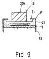
- FIG. 9is a cross-sectional view that shows a touch sensor related to the electrostatic capacitive touch sensor in accordance with Embodiment 2 of the present invention.
- FIG. 10is a cross-sectional view that shows an electrostatic capacitive touch sensor in accordance with Embodiment 3 of the present invention.
- FIG. 11is a cross-sectional view that shows an electrostatic capacitive touch sensor in accordance with Embodiment 4 of the present invention.
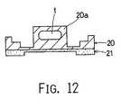
- FIG. 12is a cross-sectional view that shows an electrostatic capacitive touch sensor in accordance with Embodiment 5 of the present invention.
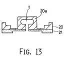
- FIG. 13is a cross-sectional view that shows a touch sensor related to the electrostatic capacitive touch sensor in accordance with Embodiment 5 of the present invention.
- FIG. 14is a cross-sectional view that shows an electrostatic capacitive touch sensor in accordance with Embodiment 6 of the present invention.
- FIG. 15is a plan view that shows fixed electrodes and a contact-use land formed on a substrate that constitute the electrostatic capacitive touch sensor;
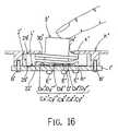
- FIG. 16is a cross-sectional view that shows a state in which the operation portion of the electrostatic capacitive touch sensor is tilted in the X-axis direction;
- FIG. 17is a cross-sectional view that shows a state in which the operation portion of the electrostatic capacitive touch sensor is pushed in the Z-axis direction;
- FIG. 18is a block diagram that shows an electrostatic capacitance-voltage conversion circuit that is used in the electrostatic capacitive touch sensor
- FIG. 19shows a specific circuit of the electrostatic capacitance-voltage conversion circuit
- FIG. 20is a cross-sectional view that shows an electrostatic capacitive touch sensor in accordance with Embodiment 7 of the present invention.
- FIG. 21is a cross-sectional view that shows an electrostatic capacitive touch sensor in accordance with Embodiment 8 of the present invention.
- FIG. 22is a cross-sectional view that shows an electrostatic capacitive touch sensor in accordance with Embodiment 9 of the present invention.
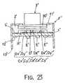
- FIG. 23is a cross-sectional view that shows an electrostatic capacitive touch sensor in accordance with Embodiment 10 of the present invention.
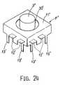
- FIG. 24is a perspective view that shows the external appearance of an electrostatic capacitive touch sensor in accordance with Embodiment 10 of the present invention.
- FIG. 25is a cross-sectional view that shows a conventional electrostatic capacitive touch sensor.
- the electrostatic capacitive touch sensor Sis provided with a substrate 1 and a movable electrode plate 2 placed on the substrate 1 , and as indicated by a two dots chain line of FIG. 1, these members are secured on the upper wall k of a casing K with machine screws B.
- a contact-use land L and fixed electrodes Dx+, Dx ⁇ , Dy+, Dy ⁇ and Dz+ covered with a resist film Rare formed on a front face of the substrate 1 , and an electronic part E used for electrostatic capacitance/voltage conversion is placed on its rear face. Moreover, penetration holes h through which the machine screws B are inserted are formed in its four corners.
- the fixed electrodes Dx+, Dx ⁇ , Dy+, Dy ⁇ and Dz+are covered with the resist film R so as to prevent these electrodes from directly contacting a conductive rubber layer section 21 which will be described later.
- the movable electrode plate 2As illustrated in FIG. 1, the movable electrode plate 2 , as a whole, is integrally molded by using elastic rubber; and more specifically, it is constituted by a silicone rubber section 20 (which may be formed by resin) on the upper side thereof and a conductive rubber layer section 21 (which may be formed by resin) on the lower side thereof.
- a silicone rubber section 20which may be formed by resin
- a conductive rubber layer section 21which may be formed by resin
- any high polymer material (elastomer)that has high rubber elasticity in the vicinity of room temperature may be adopted; and examples thereof include closslinked natural rubber, synthetic rubber, thermoplastic urethane rubber, spandex, polycarbonate elastic resins, and sponge rubber.
- a short rod-shaped operation portion 20 ais placed on the upper face of the silicone rubber section 20 so as to stick out therefrom; and a peripheral protruding portion 20 b , which exerts a sealing property when pressed against the upper wall k, is placed on the periphery thereof. Moreover, a true-circle shaped diaphragm section 20 c is formed between the operation portion 20 and the peripheral protruding portion 20 b .
- the conductive rubber layer section 21as illustrated in FIG. 1, is formed in the rear face thereof with a recessed section 21 a which has a round shape when viewed from above with a size large enough to accommodate the fixed electrodes Dx+, Dx ⁇ , Dy+, Dy ⁇ and Dz+.
- the movable electrode plate 2is designed to form a distortion-effecting body in which, when a force is applied onto the operation portion 20 a , the stress is concentrated on the diaphragm section 20 c , thereby causing a distortion therein.
- a portion of the conductive rubber layer section 21 facing the fixed electrodesis allowed to function as electrode D that forms variable electrostatic capacitive sections Cx+, Cx ⁇ , Cy+, Cy ⁇ and Cz+ in combination with the fixed electrodes Dx+, Dx ⁇ , Dy+, Dy ⁇ and Dz+, as will be described later.
- the electrostatic capacitive touch sensor Shas the following functions:
- the peripheral protruding portion 20 bUpon receipt of a pressing force from the upper wall k, the peripheral protruding portion 20 b is elastically deformed so that the conductive rubber layer section 21 and the contact-use land L come into contact with each other, thereby preventing liquid, dust, etc. from entering the variable electrostatic capacitive sections Cx+, Cx ⁇ , Cy+, Cy ⁇ and Cz+ (that is, exerting a sealing property); and the rear face of the upper wall k also comes into contact with the peripheral protruding portion 20 b , thereby preventing liquid, dust, etc. from entering a hole H formed in the upper wall k.
- the sensor S with this constructionmakes it possible to ensure the sealing properties at the respective portions without the need for installing a special plate-shaped sheet member.
- the contact between the conductive rubber layer section 21 and the contact-use land Lallows the entire conductive rubber layer section 21 of the movable electrode plate 2 to have the GND electric potential. Therefore, electric potential differences are provided between the contact-use land L and the fixed electrodes Dx+, Dx ⁇ , Dy+, Dy ⁇ and Dz+ so that the variable electrostatic capacitive sections Cx+, Cx ⁇ , Cy+, Cy ⁇ and Cz+ are exerted.
- the application of the sensor Smakes it possible to eliminate troublesome assembling tasks described in the “Prior Art”.
- the electrostatic capacitive touch sensor Shas the above-described construction, when the operation portion 20 a is operated, it functions as follows:
- the conductive rubber layer section 21 constituting the electrode Dis deformed depending on the magnitude and direction of the force that has been applied so that the electrostatic capacitances of the variable electrostatic capacitive sections Cx+, Cx ⁇ , Cy+, Cy ⁇ and Cz+ are changed correspondingly.
- the force or moment described aboveis removed from the operation portion 20 a , the elements that have been deformed and changed are returned to their original states.
- the electrostatic capacitances of the variable electrostatic capacitive sections Cx+, Cx ⁇ , Cy+, Cy ⁇ and Cz+are changed in response to the magnitude of the force applied to the three dimensional space. Therefore, when a circuit as illustrated in FIG. 5 is formed, the magnitude and direction of the force applied to the operation portion 20 a can be detected as voltage changes having respective components in X, Y and Z-axis directions. The same effects can be obtained when, instead of the circuit shown in FIG. 5, a circuit shown in FIG. 6 (in which circuits of the Y and Z axes are omitted) is adopted. In FIG. 6, it is supposed that Vx 1 and Vx 2 are allowed to change periodically.
- Embodiment 2 of the present inventionwill be described with reference to FIGS. 7 and 8.
- the reference symbol f 3shown in FIGS. 7 and 8, represents a lead terminal with solder, and through this, electric potential differences are applied between the contact-use land L and the fixed electrodes Dx+, Dx ⁇ , Dy+, Dx ⁇ and Dz+.
- the entire portion of the movable electrode plate 2 including the operation portion 20 amay be formed by conductive rubber.
- the conductive rubber layer section 21may be made in contact with the metal frame F as illustrated in FIG. 9 so that the lead terminal f 3 of the metal frame F is connected to GND.
- an independent contact-use land L 1(without the resist film R) is formed on the substrate portion surrounded by the fixed electrodes Dx+, Dx ⁇ , Dy+ and Dy ⁇ covered with the resist film; and a protrusion 21 e , which serves as an electrical contact, is formed on a portion of the conductive rubber layer section 21 opposing the contact-use land L 1 .
- the switchis thus obtained by the protrusion 21 e and the contact-use land L 1 .
- the electrostatic capacitive touch sensor S of Embodiment 4is provided with a space section t (hollow portion) inside the operation portion 20 a .
- the sensorhas an improved virtual feeling of operation.
- the top end of the operation portion 20 amay be formed into a concave- or convex-shape so as to improve the operability.
- the shape of the operation portionmay be changed depending on applications.
- the top end of the operation portionmay be formed into a shape to which a bearing, etc. may be attached so that the tension of a string may be measured.
- the electrostatic capacitive touch sensor S′is basically provided with a substrate 1 ′, a movable electrode plate 2 ′ placed on the substrate 1 ′ and an operation portion 3 ′ made of a hard material which is placed on the movable electrode plate 2 ′ so as to transmit a force to the movable electrode plate 2 ′; thus, as illustrated in the same Figure, the substrate 1 ′, placed at the lowermost position, is secured to an upper wall k′ of a casing K′ with machine screws B′.
- the substrate 1 ′is provided with a ring-shaped contact-use land L′ and fixed electrodes Dx+′, Dx ⁇ ′, Dy+′, Dy ⁇ ′ and Dz+′ covered with a resist film R′, all of which are formed on its front face, and an electronic part E′ for electrostatic capacitance/voltage conversion is placed on its rear face. Moreover, penetration holes h′ through which the machine screws B′ are inserted are formed in the four comers thereof.
- the fixed electrodes Dx+′, Dx ⁇ ′, Dy+′, Dy ⁇ ′ and Dz+′are covered with the resist film R′ so as to prevent these electrodes from directly contacting the movable electrode plate 2 ′ which will be described later.
- the movable electrode plate 2 ′is molded by using silicone rubber having a conductive property, which has a round shape when viewed from above, and as illustrated in FIG. 14, a diaphragm section 22 ′ is formed in upper and lower central portions thereof in a manner so as to form round-shaped recesses 20 ′ and 21 ′ having a size large enough to accommodate the portions covered with the resist film R′.
- the movable electrode plate 2 ′is set with a peripheral protruding portion 29 ′ along its circumferential portion being sandwiched and held by the upper wall k′ of the casing K′ and the substrate 1 ′ (thus being held with pressing forces being applied from both sides).
- the movable electrode plate 2 ′is formed by using silicone rubber; however, the present invention shall not be limited to this construction, and any high polymer material (elastomer) that exhibits high rubber elasticity in the vicinity of room temperature may be adopted; and examples thereof include closslinked natural rubber, synthetic rubber, thermoplastic urethane rubber, spandex, polycarbonate elastic resins, sponge rubber, etc.
- the operation portion 3 ′has a short rod shape made of hard resin and is provided with a peripheral protruding flange 30 ′ in the vicinity of its bottom end. Moreover, the operation portion 3 ′ is sandwiched between the movable electrode plate 2 ′ and the upper wall k′ so that the peripheral protruding flange 30 ′ and the upper wall k′ maintain contact with each other, and the rod bottom end and the bottom face of the recess 20 ′ are also maintained in contact with each other. With respect to the material used for the operation portion 3 ′, even rubber or, of course, metal may be adopted as long as it is greater in rigidity than the diaphragm section 22 of the movable electrode late 2 ′.
- the movable electrode plate 2 ′is designed so as to form a distortion-effecting body in which, when a force is applied onto the operation portion 3 ′, the stress is concentrated on the diaphragm section 22 ′, thereby causing a distortion therein; thus, a portion of the movable electrode plate 2 ′ facing the fixed electrodes is allowed to function as electrode D′ forming variable electrostatic capacitive sections Cx+′, Cx ⁇ ′, Cy+′, Cy ⁇ ′ and Cz+′ in combination with the fixed electrodes Dx+′, Dx ⁇ ′, Dy+′, Dy ⁇ ′ and Dz+′, as will be described later.
- the electrostatic capacitive touch sensor S′When the thus structured electrostatic capacitive touch sensor S′ is attached to the casing K′ as illustrated in FIG. 14, the electrostatic capacitive touch sensor S′ functions in the following manner:
- the press-contact state between the substrate 1 ′ and the peripheral protruding portion 29 ′ on the rear sidemakes it possible to prevent liquid, dust, etc. from entering the variable electrostatic capacitive sections Cx+′, Cx ⁇ ′, Cy+′, Cy ⁇ ′ and Cz+′ (thus exerting a sealing property); and the press-contact state between the rear face of the upper wall k′ and the peripheral protruding portion 29 ′ makes it possible to prevent liquid, dust, etc. from entering a hole H′ formed in the upper wall k′ (that is, to exert a sealing property).
- the assembling processis simply carried out by sandwiching the movable electrode plate 2 ′ and the operation section 3 ′ between the upper plate k′ and the substrate 1 ′ and then securing the substrate 1 ′ to the upper plate k′ with machine screws B′.
- the electrostatic capacitive touch sensor S′has the above-mentioned construction, when the operation portion 3 ′ is operated, the sensor S′ functions as follows:
- the diaphragm section 22 ′is greatly deformed so that the electrostatic capacitances of the variable electrostatic capacitive sections Cx+′, Cx ⁇ ′, Cy+′, Cy ⁇ ′ and Cz+′, formed by the diaphragm section 22 ′ functioning as the electrode D′ and the fixed electrodes Dx+′, Dx ⁇ ′, Dy+′, Dy ⁇ ′ and Dz+′, are greatly changed.
- the gap between the diaphragm section 22 ′ functioning as the electrode D′ and the fixed electrode Dx+′becomes smaller as illustrated in FIG. 16, thereby increasing the electrostatic capacitance of the variable electrostatic capacitive section Cx+′.
- the gap between the electrode D′ and the fixed electrode Dx ⁇ ′is increased or reduced; however, the amount of its change is smaller as compared with the change between the electrode D′ and the fixed electrode Dx+′, with the result that the amount of change in the electrostatic capacitance of the variable electrostatic capacitive section Cx ⁇ ′ is small.
- the gap between the electrode D′ and the fixed electrode Dz+′becomes smaller, the electrostatic capacitance of the variable electrostatic capacitive section Cz+′ becomes greater.
- the gap between the electrode D′ and the fixed electrode Dz+′becomes smaller as illustrated in FIG. 17; as a result, the electrostatic capacitance of the variable electrostatic capacitive section Cz+′ becomes greater.
- the gaps between the electrode D′ and the fixed electrodes Dx+′, Dx ⁇ ′, Dy+′ and Dy ⁇ ′become equally smaller, and the electrostatic capacitances of the variable electrostatic capacitive sections Cx+′, Cx ⁇ ′, Cy+′ and Cy ⁇ ′ become greater.
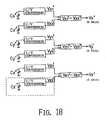
- a circuit(block diagram), as shown in FIG. 18, constituted by a plurality of electronic parts E′, is installed so that based upon the changes in the electrostatic capacitances of the variable electrostatic capacitive sections Cx+′, Cx ⁇ ′, Cy+′, Cy ⁇ ′ and Cz+′, the magnitude and direction of a force applied to the operation portion 3 ′ are detected as voltage outputs (Vx′, Vy′ and Vz′).
- symbol Cz ⁇ ′represents a dummy fixed capacitance; however, the existence of the fixed capacitance Cz ⁇ ′ is not necessarily a condition absolutely required.
- the portion of FIG. 18 surrounded by a dot linemay be replaced by a constant voltage supply.
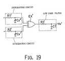
- FIG. 19shows a specific circuit corresponding to the circuit of FIG. 18 (in which circuits in the Y and Z-axes are omitted).
- symbols R 1 ′, R 2 ′ and R 3 ′are fixed resistors
- symbol EX′is an exclusive-OR circuit
- symbol C 1 ′is a fixed capacitance.
- the electrostatic capacitive touch sensor S′ of Embodiment 7has virtually the same arrangement as that of Embodiment 6; however, as illustrated in FIG. 20, a protrusion 23 ′ is installed in the center of the diaphragm 22 ′ so as to stick out downward, and the lower end of the protrusion 23 is allowed to contact (or to be placed close to) the resist film R′.
- the sensitivity in the Z-axis directionis too great as compared with the sensitivities in the X-axis and Y-axis directions; however, in the sensor S′ of Embodiment 7, the existence of the protrusion 23 ′ makes it possible to adjust and suppress the sensitivity in the Z-axis direction.
- the electrostatic capacitive touch sensor S′ of Embodiment 8has virtually the same arrangement as that of Embodiment 6; however, as illustrated in FIG. 21, with respect to the operation portion 3 ′, a rod-shaped protrusion 24 ′ is installed on the upper face of the diaphragm section 22 ′ and a cap 31 ′ is bonded to the protrusion 24 ′.
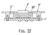
- the electrostatic capacitive touch sensor S′ of Embodiment 9has virtually the same arrangement as that of Embodiment 6; however, as illustrated in FIG. 22, the operation portion 3 ′ is a short push button.
- symbol f 3 ′represents a lead terminal with solder, and through this, electric potential differences are applied between the movable electrode plate 2 ′, the contact-use land L′ in its electrically connected state, and the fixed electrodes Dx+′, Dx ⁇ ′, Dy+′, Dx ⁇ ′ and Dz+′.
- a protrusionmay be formed on at least either one of the opposing faces of the substrate 1 ′ and the movable electrode plate 2 ′ so as to prevent the gap between the fixed electrodes and the movable electrode plate 2 ′ from becoming too narrow.
- An independent contact-use landis formed in a portion of the substrate 1 ′ surrounded by the fixed electrodes Dx+′, Dx ⁇ ′, Dy+′ and Dy ⁇ ′ that are disposed with an interval of 90° with each other, and a protrusion serving as an electric contact is formed on a portion of the movable electrode plate 2 ′ facing the contact-use land so as to form a switch by the protrusion and the contact-use land.
- the electrostatic capacitive touch sensor of the present inventionmakes it possible to reduce the number of troublesome assembling processes, and easily make the device water-proof and dust-proof without increasing the number of parts. Moreover, the electrostatic capacitive touch sensor of the present invention makes it possible to reduce the number of troublesome assembling processes, easily make the device water-proof and dust-proof without increasing the number of parts, and to provide a high sensitivity as a sensor.
Landscapes
- Engineering & Computer Science (AREA)
- Physics & Mathematics (AREA)
- General Physics & Mathematics (AREA)
- General Engineering & Computer Science (AREA)
- Theoretical Computer Science (AREA)
- Power Engineering (AREA)
- Human Computer Interaction (AREA)
- Position Input By Displaying (AREA)
Abstract
Description
1. Field of the Invention
The present invention relates to an electrostatic capacitive touch sensor.
2. Prior Art
For example, as illustrated in FIG. 25, a conventional electrostatic capacitive touch sensor typically has a construction in which asubstrate 90 having fixed electrodes Dx+, Dx−, Dy+ and Dy− and a dish-shaped metal diaphragm 91 having a conductive property with anoperation shaft 91aare formed into an integral part by arivet 92. In the touch sensor of this type, when theoperation shaft 91ais tilted, themetal diaphragm 91 is distorted, with the result that the electrostatic capacitance between themetal diaphragm 91 and the fixed electrodes Dx+, Dx−, Dy+ and Dy− are allowed to change.
However, the conventional electrostatic capacitive touch sensor described above has the following problems:
Troublesome assembling tasks, such as a joining process (caulking process, etc.) between themetal diaphragm 91 and theoperation shaft 91 and a riveting process between themetal diaphragm 91 and thesubstrate 90 are required, resulting in high costs.
Water, etc. tend to enter the gap between themetal diaphragm 91 and thesubstrate 90; therefore, an additional sealing member is required so as to make the device water-proof, depending on applications.
Therefore, one object of the present invention is to provide an electrostatic capacitive touch sensor which makes it possible to reduce the number of troublesome assembling processes and to easily make the device water-proof and dust-proof without increasing the number of parts.
Another object of the present invention is to provide an electrostatic capacitive touch sensor which makes it possible to reduce the number of troublesome assembling processes, to easily make the device water-proof and dust-proof without increasing the number of parts, and to provide a high sensitivity as a sensor.
The touch sensor according to the present invention comprises:
a substrate having a group of fixed electrodes formed thereon, and
a movable electrode plate that is integrally molded by using rubber or resin having an elastic property as a whole and has at least a face which opposes the group of fixed electrodes and is made of a conductive rubber or a conductive resin.
In this arrangement, a plurality of variable electrostatic capacitive sections are formed by the group of fixed electrodes and movable electrode plate so that, in response to the magnitude and the direction of a force applied onto the movable electrode plate, the electrostatic capacitances of the respective variable electrostatic capacitive sections are allowed to change.
The touch sensor according to the present invention comprises:
a substrate having a group of fixed electrodes formed thereon, and
a movable electrode plate that is integrally molded by using elastomer as a whole and has at least a face which opposes the group of fixed electrodes and is made of a conductive elastomer.
In this arrangement, a plurality of variable electrostatic capacitive sections are formed by the group of fixed electrodes and the movable electrode plate so that, in response to the magnitude and the direction of a force applied onto the movable electrode plate, the electrostatic capacitances of the respective variable electrostatic capacitive sections are allowed to change.
Furthermore, the touch sensor according to the present invention comprises:
a substrate having a group of fixed electrodes formed thereon,
a movable electrode plate which is formed by using elastomer as a whole and has at least a face which opposes the group of fixed electrodes and is made of a conductive elastomer, and
an operation portion made of a hard material, which is formed integrally with or separately from the movable electrode plate and can transmit force to the movable electrode plate.
In this arrangement, a plurality of variable electrostatic capacitive sections are formed by the group of fixed electrodes and movable electrode plate so that, in response to the magnitude and the direction of a force applied onto the operation portion, the electrostatic capacitances of the respective variable electrostatic capacitive sections are allowed to change.
The present invention, may have a construction in which an operation portion, made of rubber or resin, having a protruding shape, is integrally formed on the movable electrode plate.
In addition an operation portion which is made of elastomer and has a protruding shape, may be integrally formed on the movable electrode plate.
Furthermore, in the present invention, the electrodes of the group of fixed electrodes may be arranged so as to have an interval of 180° from each other; thus, based upon a change in the electrostatic capacitances between the two variable electrostatic capacitive sections, it is possible to detect the magnitude in the X-axis direction of a force applied onto the operation portion together with its positive or negative direction.
The electrodes of the group of fixed electrodes may be arranged so as to have an interval of 90° with each other; thus, based upon a change in the electrostatic capacitances between the two variable electrostatic capacitive sections that face each other on one straight line, it is possible to detect the magnitude in the X-axis direction of a force applied onto the operation portion together with its positive or negative direction, and based upon a change in the electrostatic capacitances between the two variable electrostatic capacitive sections that face each other on the other straight line, it is possible to detect the magnitude in the Y-axis direction of a force applied onto the operation portion together with its positive or negative direction.
Furthermore, an independent electrode may be formed on a substrate portion surrounded by four electrodes arranged with an interval of 90° with each other; thus, based upon a change in the electrostatic capacitance of the variable electrostatic capacitive section that is formed by the independent electrode and the variable electrode plate, it is possible to detect the magnitude in the Z-axis direction of a force applied onto the operation portion together with its positive or negative direction.
In addition, an independent contact-use land may be formed on the substrate portion surrounded by four electrodes arranged with an interval of 90° with each other, and a protrusion serving as an electrical contact may be formed on a portion of the movable electrode plate opposing the contact-use land; thus, the switch is constructed by the protrusion and the contact-use land.
Furthermore, in the present invention, a peripheral protruding portion may be formed on the movable electrode plate so as to surround the operation portion; therefore, when the movable electrode plate is attached to a fixing member with the peripheral protruding portion being pressed thereon, it is possible to ensure a sealing property between the fixing member and the movable electrode plate by the elastic restoration force of the peripheral protruding portion.
The substrate and the movable electrode plate may be enclosed by a metal frame, and one portion of the metal frame is bent over so that the movable electrode plate and the substrate are secured to the metal frame in a manner so as to be pressed thereon; thus, it becomes possible to prevent foreign matters from entering the variable electrostatic capacitive section from outside by using a sealing property exerted by the elastic restoration force of the movable electrode plate.
In the present invention, the metal frame has a conductive property so that the movable electrode plate is allowed to hold a predetermined voltage through the metal frame. Furthermore, a protrusion may be formed on at least either one of the opposing faces of the substrate and the movable electrode plate so as to prevent the gap between the group of fixed electrodes and the movable electrode plate from becoming too narrow the operation portion may be provided with a space, and the operation portion may be made of rubber, resin or metal.
FIG. 1 is a cross-sectional view that shows an assembled state of an electrostatic capacitive touch sensor in accordance withEmbodiment 1 of the present invention;
FIG. 2 is a plan view that shows the touch sensor and fixed electrodes;
FIG. 3 is a cross-sectional view that shows a state in which a force or a moment in the X-axis direction is exerted on the operation portion of the touch sensor;
FIG. 4 is a cross-sectional view that shows a state in which a force in the Z-axis direction is exerted on the operation portion of the touch sensor;
FIG. 5 is a circuit diagram that is used in the touch sensor;
FIG. 6 is a circuit diagram that is used in another embodiment of the touch sensor;
FIG. 7 is a cross-sectional view that shows an electrostatic capacitive touch sensor in accordance withEmbodiment 2 of the present invention;
FIG. 8 is a perspective view that shows the external appearance of the electrostatic capacitive touch sensor in accordance withEmbodiment 2 of the present invention;
FIG. 9 is a cross-sectional view that shows a touch sensor related to the electrostatic capacitive touch sensor in accordance withEmbodiment 2 of the present invention;
FIG. 10 is a cross-sectional view that shows an electrostatic capacitive touch sensor in accordance withEmbodiment 3 of the present invention;
FIG. 11 is a cross-sectional view that shows an electrostatic capacitive touch sensor in accordance with Embodiment 4 of the present invention;
FIG. 12 is a cross-sectional view that shows an electrostatic capacitive touch sensor in accordance with Embodiment 5 of the present invention;
FIG. 13 is a cross-sectional view that shows a touch sensor related to the electrostatic capacitive touch sensor in accordance with Embodiment 5 of the present invention;
FIG. 14 is a cross-sectional view that shows an electrostatic capacitive touch sensor in accordance with Embodiment 6 of the present invention;
FIG. 15 is a plan view that shows fixed electrodes and a contact-use land formed on a substrate that constitute the electrostatic capacitive touch sensor;
FIG. 16 is a cross-sectional view that shows a state in which the operation portion of the electrostatic capacitive touch sensor is tilted in the X-axis direction;
FIG. 17 is a cross-sectional view that shows a state in which the operation portion of the electrostatic capacitive touch sensor is pushed in the Z-axis direction;
FIG. 18 is a block diagram that shows an electrostatic capacitance-voltage conversion circuit that is used in the electrostatic capacitive touch sensor;
FIG. 19 shows a specific circuit of the electrostatic capacitance-voltage conversion circuit;
FIG. 20 is a cross-sectional view that shows an electrostatic capacitive touch sensor in accordance with Embodiment 7 of the present invention;
FIG. 21 is a cross-sectional view that shows an electrostatic capacitive touch sensor in accordance with Embodiment 8 of the present invention;
FIG. 22 is a cross-sectional view that shows an electrostatic capacitive touch sensor in accordance with Embodiment 9 of the present invention;
FIG. 23 is a cross-sectional view that shows an electrostatic capacitive touch sensor in accordance with Embodiment 10 of the present invention;
FIG. 24 is a perspective view that shows the external appearance of an electrostatic capacitive touch sensor in accordance with Embodiment 10 of the present invention; and
FIG. 25 is a cross-sectional view that shows a conventional electrostatic capacitive touch sensor.
As illustrated in FIG. 1, the electrostatic capacitive touch sensor S is provided with asubstrate 1 and amovable electrode plate 2 placed on thesubstrate 1, and as indicated by a two dots chain line of FIG. 1, these members are secured on the upper wall k of a casing K with machine screws B.
As illustrated in FIGS. 1 and 2, a contact-use land L and fixed electrodes Dx+, Dx−, Dy+, Dy− and Dz+ covered with a resist film R are formed on a front face of thesubstrate 1, and an electronic part E used for electrostatic capacitance/voltage conversion is placed on its rear face. Moreover, penetration holes h through which the machine screws B are inserted are formed in its four corners. The fixed electrodes Dx+, Dx−, Dy+, Dy− and Dz+ are covered with the resist film R so as to prevent these electrodes from directly contacting a conductiverubber layer section 21 which will be described later.
As illustrated in FIG. 1, themovable electrode plate 2, as a whole, is integrally molded by using elastic rubber; and more specifically, it is constituted by a silicone rubber section20 (which may be formed by resin) on the upper side thereof and a conductive rubber layer section21 (which may be formed by resin) on the lower side thereof. With respect to the material of themovable electrode plate 2, any high polymer material (elastomer) that has high rubber elasticity in the vicinity of room temperature may be adopted; and examples thereof include closslinked natural rubber, synthetic rubber, thermoplastic urethane rubber, spandex, polycarbonate elastic resins, and sponge rubber.
As illustrated in FIG. 1, a short rod-shapedoperation portion 20ais placed on the upper face of thesilicone rubber section 20 so as to stick out therefrom; and a peripheral protrudingportion 20b, which exerts a sealing property when pressed against the upper wall k, is placed on the periphery thereof. Moreover, a true-circle shapeddiaphragm section 20cis formed between theoperation portion 20 and the peripheral protrudingportion 20b. The conductiverubber layer section 21, as illustrated in FIG. 1, is formed in the rear face thereof with a recessedsection 21awhich has a round shape when viewed from above with a size large enough to accommodate the fixed electrodes Dx+, Dx−, Dy+, Dy− and Dz+.
Here, themovable electrode plate 2 is designed to form a distortion-effecting body in which, when a force is applied onto theoperation portion 20a, the stress is concentrated on thediaphragm section 20c, thereby causing a distortion therein. Thus, a portion of the conductiverubber layer section 21 facing the fixed electrodes is allowed to function as electrode D that forms variable electrostatic capacitive sections Cx+, Cx−, Cy+, Cy− and Cz+ in combination with the fixed electrodes Dx+, Dx−, Dy+, Dy− and Dz+, as will be described later.
In an attached state to the casing K as illustrated in FIG. 1, the electrostatic capacitive touch sensor S has the following functions:
Upon receipt of a pressing force from the upper wall k, the peripheral protrudingportion 20bis elastically deformed so that the conductiverubber layer section 21 and the contact-use land L come into contact with each other, thereby preventing liquid, dust, etc. from entering the variable electrostatic capacitive sections Cx+, Cx−, Cy+, Cy− and Cz+ (that is, exerting a sealing property); and the rear face of the upper wall k also comes into contact with the peripheral protrudingportion 20b, thereby preventing liquid, dust, etc. from entering a hole H formed in the upper wall k. In other words, the sensor S with this construction makes it possible to ensure the sealing properties at the respective portions without the need for installing a special plate-shaped sheet member.
The contact between the conductiverubber layer section 21 and the contact-use land L allows the entire conductiverubber layer section 21 of themovable electrode plate 2 to have the GND electric potential. Therefore, electric potential differences are provided between the contact-use land L and the fixed electrodes Dx+, Dx−, Dy+, Dy− and Dz+ so that the variable electrostatic capacitive sections Cx+, Cx−, Cy+, Cy− and Cz+ are exerted.
Additionally, the application of the sensor S makes it possible to eliminate troublesome assembling tasks described in the “Prior Art”.
Since the electrostatic capacitive touch sensor S has the above-described construction, when theoperation portion 20ais operated, it functions as follows:
First, as illustrated in FIG. 3, when a force Fx or a moment Mx in the X-axis direction is applied to theoperation portion 20a, the gap between the electrode D and the fixed electrode Dx+ is narrowed, with the result that the electrostatic capacitance of the variable electrostatic capacitive section Cx+ becomes greater. In contrast, the gap between the electrode D and the fixed electrode Dx− does not change or it becomes greater, with the result that the electrostatic capacitance of the variable electrostatic capacitive section Cx+ does not change or it becomes smaller. Because of the symmetrical characteristic, the same is true for the fixed electrodes Dy+ and Dy− in the case when a force Fy or a moment My in the Y-axis direction is applied thereto. In other words, with respect to the XY plane, the conductiverubber layer section 21 constituting the electrode D is deformed depending on the magnitude and direction of the force that has been applied so that the electrostatic capacitances of the variable electrostatic capacitive sections Cx+, Cx−, Cy+, Cy− and Cz+ are changed correspondingly. When the force or moment described above is removed from theoperation portion 20a, the elements that have been deformed and changed are returned to their original states.
Next, as illustrated in FIG. 4, when a force Fz in the Z-axis direction is applied, the gap between the electrode D and the fixed electrode Dz+ becomes smaller, with the result that the electrostatic capacitance of the variable electrostatic capacitive section Cz+ becomes greater. Moreover, the gaps between the electrode D and the fixed electrodes Dx+, Dx−, Dy+, Dy− and Dz+ are narrowed in a uniform manner, with the result that the electrostatic capacitances of the variable electrostatic capacitive sections Cx+, Cx−, Cy+ and Cy− become greater in a virtually uniform manner.
As seen from the above, the electrostatic capacitances of the variable electrostatic capacitive sections Cx+, Cx−, Cy+, Cy− and Cz+ are changed in response to the magnitude of the force applied to the three dimensional space. Therefore, when a circuit as illustrated in FIG. 5 is formed, the magnitude and direction of the force applied to theoperation portion 20acan be detected as voltage changes having respective components in X, Y and Z-axis directions. The same effects can be obtained when, instead of the circuit shown in FIG. 5, a circuit shown in FIG. 6 (in which circuits of the Y and Z axes are omitted) is adopted. In FIG. 6, it is supposed that Vx1 and Vx2 are allowed to change periodically.
In this Embodiment, a provision is made so as to solely assemble the device, and as illustrated in FIGS. 7 and 8, thesubstrate 1 and themovable electrode plate 2 are housed in a metal frame F, and thesubstrate 1 and themovable electrode plate 2 in their laminated state are sandwiched and held by an upper wall f1 and a bent portion f2 of the metal frame F. Therefore, in the same manner as inEmbodiment 1 , it is possible to prevent liquid, dust, etc. from entering the variable electrostatic capacitive sections Cx+, Cx−, Cy+, Cy− and Cz+ (that is, to exert a sealing property); and the conductiverubber layer section 21 and the contact-use land L come into contact with each other so that the conductiverubber layer section 21 of themovable electrode plate 2, as a whole, is allowed to have the GND electric potential. The reference symbol f3, shown in FIGS. 7 and 8, represents a lead terminal with solder, and through this, electric potential differences are applied between the contact-use land L and the fixed electrodes Dx+, Dx−, Dy+, Dx− and Dz+.
Here, the entire portion of themovable electrode plate 2 including theoperation portion 20amay be formed by conductive rubber.
Moreover, with respect to the means for allowing the conductiverubber layer section 21 to have the GND (ground) electric potential, instead of installing the contact-use land L in this embodiment, the conductiverubber layer section 21 may be made in contact with the metal frame F as illustrated in FIG. 9 so that the lead terminal f3 of the metal frame F is connected to GND.
In the electrostatic capacitive touch sensor S ofEmbodiment 3, as illustrated in FIG. 10, only the fixed electrodes Dx+, Dx−, Dy+ and Dy−, covered with a resist film R, are placed on thesubstrate 1, and aprotrusion 21dis attached to a portion of the conductiverubber layer section 21 opposing the portion surrounded by the fixed electrodes Dx+, Dx−, Dy+ and Dy− (the portion corresponding to Dz+ in FIGS. 1 and 7) in a manner so as to stick out downward. In this sensor S, the lower end of theprotrusion 21dis allowed to contact thesubstrate 1 so that theprotrusion 21dfunctions like the fulcrum of a lever. Therefore, when the sensor S having this construction is used as a joystick, it is possible to make the operability more stable.
As illustrated in FIG. 11, in the electrostatic capacitive touch sensor S in Embodiment 4, an independent contact-use land L1 (without the resist film R) is formed on the substrate portion surrounded by the fixed electrodes Dx+, Dx−, Dy+ and Dy− covered with the resist film; and aprotrusion 21e, which serves as an electrical contact, is formed on a portion of the conductiverubber layer section 21 opposing the contact-use land L1. The switch is thus obtained by theprotrusion 21eand the contact-use land L1.
As illustrated in FIGS. 12 and 13, the electrostatic capacitive touch sensor S of Embodiment 4 is provided with a space section t (hollow portion) inside theoperation portion 20a. Thus, the sensor has an improved virtual feeling of operation.
InEmbodiments 1 through 5, as illustrated in FIGS. 12 and 13, the top end of theoperation portion 20amay be formed into a concave- or convex-shape so as to improve the operability.
In the case when a force is applied by other than the hand, the shape of the operation portion may be changed depending on applications. For example, the top end of the operation portion may be formed into a shape to which a bearing, etc. may be attached so that the tension of a string may be measured.
In this Embodiment 6 of the present invention as illustrated in FIG. 14, the electrostatic capacitive touch sensor S′ is basically provided with asubstrate 1′, amovable electrode plate 2′ placed on thesubstrate 1′ and anoperation portion 3′ made of a hard material which is placed on themovable electrode plate 2′ so as to transmit a force to themovable electrode plate 2′; thus, as illustrated in the same Figure, thesubstrate 1′, placed at the lowermost position, is secured to an upper wall k′ of a casing K′ with machine screws B′.
As illustrated in FIGS. 14 and 15, thesubstrate 1′ is provided with a ring-shaped contact-use land L′ and fixed electrodes Dx+′, Dx−′, Dy+′, Dy−′ and Dz+′ covered with a resist film R′, all of which are formed on its front face, and an electronic part E′ for electrostatic capacitance/voltage conversion is placed on its rear face. Moreover, penetration holes h′ through which the machine screws B′ are inserted are formed in the four comers thereof. The fixed electrodes Dx+′, Dx−′, Dy+′, Dy−′ and Dz+′ are covered with the resist film R′ so as to prevent these electrodes from directly contacting themovable electrode plate 2′ which will be described later.
Themovable electrode plate 2′ is molded by using silicone rubber having a conductive property, which has a round shape when viewed from above, and as illustrated in FIG. 14, adiaphragm section 22′ is formed in upper and lower central portions thereof in a manner so as to form round-shapedrecesses 20′ and21′ having a size large enough to accommodate the portions covered with the resist film R′. As illustrated in FIG. 14, themovable electrode plate 2′ is set with a peripheral protrudingportion 29′ along its circumferential portion being sandwiched and held by the upper wall k′ of the casing K′ and thesubstrate 1′ (thus being held with pressing forces being applied from both sides). In this Embodiment, themovable electrode plate 2′ is formed by using silicone rubber; however, the present invention shall not be limited to this construction, and any high polymer material (elastomer) that exhibits high rubber elasticity in the vicinity of room temperature may be adopted; and examples thereof include closslinked natural rubber, synthetic rubber, thermoplastic urethane rubber, spandex, polycarbonate elastic resins, sponge rubber, etc.
As illustrated in FIG. 14, theoperation portion 3′ has a short rod shape made of hard resin and is provided with a peripheral protrudingflange 30′ in the vicinity of its bottom end. Moreover, theoperation portion 3′ is sandwiched between themovable electrode plate 2′ and the upper wall k′ so that the peripheral protrudingflange 30′ and the upper wall k′ maintain contact with each other, and the rod bottom end and the bottom face of therecess 20′ are also maintained in contact with each other. With respect to the material used for theoperation portion 3′, even rubber or, of course, metal may be adopted as long as it is greater in rigidity than thediaphragm section 22 of the movable electrode late2′.
Here, as illustrated in FIG. 14, themovable electrode plate 2′ is designed so as to form a distortion-effecting body in which, when a force is applied onto theoperation portion 3′, the stress is concentrated on thediaphragm section 22′, thereby causing a distortion therein; thus, a portion of themovable electrode plate 2′ facing the fixed electrodes is allowed to function as electrode D′ forming variable electrostatic capacitive sections Cx+′, Cx−′, Cy+′, Cy−′ and Cz+′ in combination with the fixed electrodes Dx+′, Dx−′, Dy+′, Dy−′ and Dz+′, as will be described later.
When the thus structured electrostatic capacitive touch sensor S′ is attached to the casing K′ as illustrated in FIG. 14, the electrostatic capacitive touch sensor S′ functions in the following manner:
Since the peripheral protrudingportion 29′ of themovable electrode plate 2′ is sandwiched and held by the upper wall k′ of the casing K′ and thesubstrate 1′, the press-contact state between thesubstrate 1′ and the peripheral protrudingportion 29′ on the rear side makes it possible to prevent liquid, dust, etc. from entering the variable electrostatic capacitive sections Cx+′, Cx−′, Cy+′, Cy−′ and Cz+′ (thus exerting a sealing property); and the press-contact state between the rear face of the upper wall k′ and the peripheral protrudingportion 29′ makes it possible to prevent liquid, dust, etc. from entering a hole H′ formed in the upper wall k′ (that is, to exert a sealing property).
The above-described press-contact state of the peripheral protrudingportion 29′ of themovable electrode plate 2′ and the contact-use land L′ allows themovable electrode plate 2′ to have the GND electric potential. Therefore, electric potential differences are provided between the contact-use land L′ and the fixed electrodes Dx+′, Dx−′, Dy+′, Dy−′ and Dz+′ so that the variable electrostatic capacitive sections Cx+′, Cx−′, Cy+′, Cy−′ and Cz+′ are exerted.
The assembling process is simply carried out by sandwiching themovable electrode plate 2′ and theoperation section 3′ between the upper plate k′ and thesubstrate 1′ and then securing thesubstrate 1′ to the upper plate k′ with machine screws B′.
Since the electrostatic capacitive touch sensor S′ has the above-mentioned construction, when theoperation portion 3′ is operated, the sensor S′ functions as follows:
In this sensor S′, when a force is applied to theoperation portion 3′, thediaphragm section 22′ of themovable electrode 2′ is greatly deformed; however, since theoperation portion 3′ is greater in rigidity as compared with themovable electrode plate 2′, the force applied to theoperation section 3′ is effectively transmitted to thediaphragm section 22′. Therefore, thediaphragm section 22′ is greatly deformed so that the electrostatic capacitances of the variable electrostatic capacitive sections Cx+′, Cx−′, Cy+′, Cy−′ and Cz+′, formed by thediaphragm section 22′ functioning as the electrode D′ and the fixed electrodes Dx+′, Dx−′, Dy+′, Dy−′ and Dz+′, are greatly changed.
Here, when a tilting force is applied to theoperation portion 3′, the gap between thediaphragm section 22′ functioning as the electrode D′ and the fixed electrode Dx+′ becomes smaller as illustrated in FIG. 16, thereby increasing the electrostatic capacitance of the variable electrostatic capacitive section Cx+′. In contrast, the gap between the electrode D′ and the fixed electrode Dx−′ is increased or reduced; however, the amount of its change is smaller as compared with the change between the electrode D′ and the fixed electrode Dx+′, with the result that the amount of change in the electrostatic capacitance of the variable electrostatic capacitive section Cx−′ is small. Moreover, in this case, since the gap between the electrode D′ and the fixed electrode Dz+′ becomes smaller, the electrostatic capacitance of the variable electrostatic capacitive section Cz+′ becomes greater.
Moreover, when a force in a push-in direction is applied to theoperation portion 3′, the gap between the electrode D′ and the fixed electrode Dz+′ becomes smaller as illustrated in FIG. 17; as a result, the electrostatic capacitance of the variable electrostatic capacitive section Cz+′ becomes greater. In the same manner, the gaps between the electrode D′ and the fixed electrodes Dx+′, Dx−′, Dy+′ and Dy−′ become equally smaller, and the electrostatic capacitances of the variable electrostatic capacitive sections Cx+′, Cx−′, Cy+′ and Cy−′ become greater.
In the electrostatic capacitive touch sensor S′, a circuit (block diagram), as shown in FIG. 18, constituted by a plurality of electronic parts E′, is installed so that based upon the changes in the electrostatic capacitances of the variable electrostatic capacitive sections Cx+′, Cx−′, Cy+′, Cy−′ and Cz+′, the magnitude and direction of a force applied to theoperation portion 3′ are detected as voltage outputs (Vx′, Vy′ and Vz′). Here, in FIG.18, symbol Cz−′ represents a dummy fixed capacitance; however, the existence of the fixed capacitance Cz−′ is not necessarily a condition absolutely required. Moreover, the portion of FIG. 18 surrounded by a dot line may be replaced by a constant voltage supply.
FIG. 19 shows a specific circuit corresponding to the circuit of FIG. 18 (in which circuits in the Y and Z-axes are omitted). In FIG. 19, symbols R1′, R2′ and R3′ are fixed resistors, symbol EX′ is an exclusive-OR circuit, and symbol C1′ is a fixed capacitance.
The electrostatic capacitive touch sensor S′ of Embodiment 7 has virtually the same arrangement as that of Embodiment 6; however, as illustrated in FIG. 20, aprotrusion 23′ is installed in the center of thediaphragm 22′ so as to stick out downward, and the lower end of theprotrusion 23 is allowed to contact (or to be placed close to) the resist film R′.
In the sensor S′ of Embodiment 6 in which themovable electrode plate 2′ is made of silicone rubber, the sensitivity in the Z-axis direction is too great as compared with the sensitivities in the X-axis and Y-axis directions; however, in the sensor S′ of Embodiment 7, the existence of theprotrusion 23′ makes it possible to adjust and suppress the sensitivity in the Z-axis direction.
The electrostatic capacitive touch sensor S′ of Embodiment 8 has virtually the same arrangement as that of Embodiment 6; however, as illustrated in FIG. 21, with respect to theoperation portion 3′, a rod-shapedprotrusion 24′ is installed on the upper face of thediaphragm section 22′ and acap 31′ is bonded to theprotrusion 24′.
The electrostatic capacitive touch sensor S′ of Embodiment 9 has virtually the same arrangement as that of Embodiment 6; however, as illustrated in FIG. 22, theoperation portion 3′ is a short push button.
As illustrated in FIGS. 23 and 24, in the electrostatic capacitive touch sensor S′ in Embodiment 10, provision is made so as to solely assemble the device; and thesubstrate 1′, themovable electrode plate 2′ and theoperation portion 3′ are housed in a metal frame F′ in a stacked manner, and thesubstrate 1′, themovable electrode plate 2′ and theoperation portion 3′ in their laminated state are sandwiched and held by an upper wall f1′ and a bent portion f2′ of the metal frame F′. Here, in FIG. 23, symbol f3′ represents a lead terminal with solder, and through this, electric potential differences are applied between themovable electrode plate 2′, the contact-use land L′ in its electrically connected state, and the fixed electrodes Dx+′, Dx−′, Dy+′, Dx−′ and Dz+′.
A protrusion may be formed on at least either one of the opposing faces of thesubstrate 1′ and themovable electrode plate 2′ so as to prevent the gap between the fixed electrodes and themovable electrode plate 2′ from becoming too narrow.
An independent contact-use land is formed in a portion of thesubstrate 1′ surrounded by the fixed electrodes Dx+′, Dx−′, Dy+′ and Dy−′ that are disposed with an interval of 90° with each other, and a protrusion serving as an electric contact is formed on a portion of themovable electrode plate 2′ facing the contact-use land so as to form a switch by the protrusion and the contact-use land.
As seen from the above, the electrostatic capacitive touch sensor of the present invention makes it possible to reduce the number of troublesome assembling processes, and easily make the device water-proof and dust-proof without increasing the number of parts. Moreover, the electrostatic capacitive touch sensor of the present invention makes it possible to reduce the number of troublesome assembling processes, easily make the device water-proof and dust-proof without increasing the number of parts, and to provide a high sensitivity as a sensor.
Claims (28)
1. An electrostatic capacitive touch sensor, comprising:
a substrate having a group of fixed electrodes which are disposed to work as a pair formed thereon; and
a movable electrode plate that is integrally molded from a material selected from the group consisting of rubber and resin having an elastic property as a whole and has at least a face which opposes the group of fixed electrodes, said face being made from a material selected from the group consisting of a conductive rubber and a conductive resin, said movable electrode plate being provided with a protrusion which extends downward and a lower end of which is in contact with a center portion of said group of fixed electrodes of said substrate, wherein
the group of fixed electrodes and the movable electrode plate are allowed to form a plurality of variable electrostatic capacitive sections, and wherein
in response to the magnitude and direction of a force applied onto the movable electrode plate, the electrostatic capacitances of the respective variable electrostatic capacitive sections are allowed to change.
2. The electrostatic capacitive touch sensor according toclaim 1 , wherein the group of fixed electrodes are arranged so as to have an interval of 180° from each other, and wherein, based upon a change in the electrostatic capacitances between two variable electrostatic capacitive sections, a magnitude in an X-axis direction of a force applied onto the operation portion is detected together with a positive or negative direction thereof.
3. The electrostatic capacitive touch sensor according toclaim 1 , wherein the substrate and the movable electrode plate are enclosed by a metal frame, and one portion of the metal frame is bent over so that the movable electrode plate and the substrate are secured to the metal frame in a manner so as to be pressed thereon, and wherein foreign matters are prevented from entering the variable electrostatic capacitive section from outside by using a sealing property exerted by the elastic restoration force of the movable electrode plate.
4. The electrostatic capacitive touch sensor according toclaim 3 , wherein the metal frame has a conductive property so that the movable electrode plate is allowed to hold a predetermined voltage through the metal frame.
5. The electrostatic capacitive touch sensor according toclaim 1 , wherein the electrodes of the group of fixed electrodes are arranged so as to have an interval of 90° with each other, and wherein,
based upon a change in the electrostatic capacitances between two variable electrostatic capacitive sections that face each other on one straight line, a magnitude in an X-axis direction of a force applied onto the operation portion is detected together with a positive or negative direction thereof; and
based upon a change in the electrostatic capacitances between the two variable electrostatic capacitive sections that face each other on the other straight line, a magnitude in a Y-axis direction of a force applied onto the operation portion is detected together with a positive or negative direction thereof.
6. The electrostatic capacitive touch sensor according toclaim 5 , wherein an independent electrode is formed on a substrate portion surrounded by four electrodes disposed with an interval of 90° with each other, and wherein, based upon a change in the electrostatic capacitance of the variable electrostatic capacitive section that is formed by the independent electrode and the variable electrode plate, a magnitude in a Z-axis direction of a force applied onto the operation portion is detected together with a positive or negative direction thereof.
7. The electrostatic capacitive touch sensor according toclaim 1 , further comprising an operation portion for transmitting force to said movable electrode plate, said operation portion being made of rubber or resin, having a protruding shape and being integrally molded with the movable electrode plate.
8. The electrostatic capacitive touch sensor according toclaim 7 , wherein the operation portion is provided with a space section.
9. The electrostatic capacitive touch sensor according toclaim 7 , wherein a peripheral protruding portion is formed on the movable electrode plate so as to surround the operation portion, and wherein when the movable electrode plate is attached to a fixing member with the peripheral protruding portion being pressed thereon, a sealing property between the fixing member and the movable electrode plate is secured by the elastic restoration force of the peripheral protruding portion.
10. An electrostatic capacitive touch sensor, comprising:
a substrate having a group of fixed electrodes which are disposed to work as a pair formed thereon; and
a movable electrode plate that is integrally molded from an elastomer as a whole and has at least a face which opposes the group of fixed electrodes, said face being made of a conductive elastomer, said movable electrode plate being provided with a protrusion which extends downward and a lower end of which is in contact with a center portion of said group of fixed electrodes of said substrate, wherein
the group of fixed electrodes and the movable electrode plate are allowed to form a plurality of variable electrostatic capacitive sections, and wherein
in response to the magnitude and direction of a force applied onto the movable electrode plate, the electrostatic capacitances of the respective variable electrostatic capacitive sections are allowed to change.
11. The electrostatic capacitive touch sensor according toclaim 10 , wherein the group of fixed electrodes are arranged so as to have an interval of 180° from each other, and wherein, based upon a change in the electrostatic capacitances between the two variable electrostatic capacitive sections, a magnitude in an X-axis direction of a force applied onto the operation portion is detected together with a positive or negative direction thereof.
12. The electrostatic capacitive touch sensor according toclaim 10 , wherein the substrate and the movable electrode plate are enclosed by a metal frame, and one portion of the metal frame is bent over so that the movable electrode plate and the substrate are secured to the metal frame in a manner so as to be pressed thereon, and wherein foreign matters are prevented from entering the variable electrostatic capacitive section from outside by using a sealing property exerted by the elastic restoration force of the movable electrode plate.
13. The electrostatic capacitive touch sensor according toclaim 12 , wherein the metal frame has a conductive property so that the movable electrode plate is allowed to hold a predetermined voltage through the metal frame.
14. The electrostatic capacitive touch sensor according toclaim 10 , wherein the electrodes of the group of fixed electrodes are arranged so as to have an interval of 90° with each other, and wherein,
based upon a change in the electrostatic capacitances between two variable electrostatic capacitive sections that face each other on one straight line, a magnitude in an X-axis direction of a force applied onto the operation portion is detected together with a positive or negative direction thereof; and
based upon a change in the electrostatic capacitances between the two variable electrostatic capacitive sections that face each other on the other straight line, a magnitude in a Y-axis direction of a force applied onto the operation portion is detected together with a positive or negative direction thereof.
15. The electrostatic capacitive touch sensor according toclaim 14 , wherein an independent electrode is formed on a substrate portion surrounded by four electrodes disposed with an interval of 90° with each other, and wherein, based upon a change in the electrostatic capacitance of the variable electrostatic capacitive section that is formed by the independent electrode and the variable electrode plate, a magnitude in a Z-axis direction of a force applied onto the operation portion is detected together with a positive or negative direction thereof.
16. The electrostatic capacitive touch sensor according toclaim 10 , further comprising an operation portion for transmitting force to said movable electrode plate, said operation portion being made of elastomer, having a protruding shape and being integrally molded with the movable electrode plate.
17. The electrostatic capacitive touch sensor according toclaim 16 , wherein the operation portion is provided with a space section.
18. The electrostatic capacitive touch sensor according toclaim 16 , wherein a peripheral protruding portion is formed on the movable electrode plate so as to surround the operation portion, and wherein when the movable electrode plate is attached to a fixing member with the peripheral protruding portion being pressed thereon, a sealing property between the fixing member and the movable electrode plate is secured by the elastic restoration force of the peripheral protruding portion.
19. An electrostatic capacitive touch sensor, comprising:
a substrate having a group of fixed electrodes formed thereon;
a movable electrode plate that is molded by using elastomer and has at least a face that opposes the group of fixed electrodes and is made of a conductive elastomer; and
an operation portion which is made of a hard material, formed integrally with the movable electrode plate or separately from the movable electrode plate and can transmit force to the movable electrode plate, wherein
the group of fixed electrodes and the movable electrode plate are allowed to form a plurality of variable electrostatic capacitive sections, and wherein
in response to the magnitude and direction of a force applied onto the movable electrode plate, the electrostatic capacitances of the respective variable electrostatic capacitive sections are allowed to change.
20. The electrostatic capacitive touch sensor according toclaim 19 , wherein the group of fixed electrodes are arranged so as to have an interval of 180° from each other, and wherein, based upon a change in the electrostatic capacitances between the two variable electrostatic capacitive sections, a magnitude in an X-axis direction of a force applied onto the operation portion is detected together with a positive or negative direction thereof.
21. The electrostatic capacitive touch sensor according toclaim 19 , wherein a peripheral protruding portion is formed on the movable electrode plate so as to surround the operation portion, and wherein when the movable electrode plate is attached to a fixing member with the peripheral protruding portion being pressed thereon, a sealing property between the fixing member and the movable electrode plate is secured by the elastic restoration force of the peripheral protruding portion.
22. The electrostatic capacitive touch sensor according toclaim 19 , wherein a protrusion is formed on at least either one of the opposing faces of the substrate and the movable electrode plate so as to prevent the gap between the group of fixed electrodes and the movable electrode plate from becoming too narrow.
23. The electrostatic capacitive touch sensor according toclaim 19 , wherein the operation portion is made of rubber, resin or metal.
24. The electrostatic capacitive touch sensor according toclaim 19 , wherein the substrate and the movable electrode plate are enclosed by a metal frame, and one portion of the metal frame is bent over so that the movable electrode plate and the substrate are secured to the metal frame in a manner so as to be pressed thereon, and wherein foreign matters are prevented from entering the variable electrostatic capacitive section from outside by using a sealing property exerted by the elastic restoration force of the movable electrode plate.
25. The electrostatic capacitive touch sensor according toclaim 24 , wherein the metal frame has a conductive property so that the movable electrode plate is allowed to hold a predetermined voltage through the metal frame.
26. The electrostatic capacitive touch sensor according toclaim 19 , wherein the electrodes of the group of fixed electrodes are arranged so as to have an interval of 90° with each other, and wherein,
based upon a change in the electrostatic capacitances between two variable electrostatic capacitive sections that face each other on one straight line, a magnitude in an X-axis direction of a force applied onto the operation portion is detected together with a positive or negative direction thereof; and
based upon a change in the electrostatic capacitances between the two variable electrostatic capacitive sections that face each other on the other straight line, a magnitude in a Y-axis direction of a force applied onto the operation portion is detected together with a positive or negative direction thereof.
27. The electrostatic capacitive touch sensor according toclaim 26 , wherein an independent electrode is formed on a substrate portion surrounded by four electrodes disposed with an interval of 90° with each other, and wherein, based upon a change in the electrostatic capacitance of the variable electrostatic capacitive section that is formed by the independent electrode and the variable electrode plate, a magnitude in a Z-axis direction of a force applied onto the operation portion is detected together with and a positive or negative direction thereof.
28. The electrostatic capacitive touch sensor according toclaim 27 , wherein an independent contact-use land is formed on the substrate portion surrounded by four electrodes disposed with an interval of 90° with each other and a protrusion serving as an electrical contact is formed on a portion of the movable electrode plate opposing the contact-use land, so that a switch is constructed by the protrusion and the contact-use land.
Applications Claiming Priority (6)
| Application Number | Priority Date | Filing Date | Title |
|---|---|---|---|
| JP2512899 | 1999-02-02 | ||
| JP11-025128 | 1999-02-02 | ||
| JP19864599AJP3413464B2 (en) | 1999-07-13 | 1999-07-13 | Capacitive force sensor |
| JP11-198645 | 1999-07-13 | ||
| JP11-247476 | 1999-09-01 | ||
| JP24747699AJP3380996B2 (en) | 1999-02-02 | 1999-09-01 | Capacitive force sensor |
Publications (1)
| Publication Number | Publication Date |
|---|---|
| US6373265B1true US6373265B1 (en) | 2002-04-16 |
Family
ID=27284901
Family Applications (1)
| Application Number | Title | Priority Date | Filing Date |
|---|---|---|---|
| US09/497,065Expired - Fee RelatedUS6373265B1 (en) | 1999-02-02 | 2000-02-02 | Electrostatic capacitive touch sensor |
Country Status (1)
| Country | Link |
|---|---|
| US (1) | US6373265B1 (en) |
Cited By (118)
| Publication number | Priority date | Publication date | Assignee | Title |
|---|---|---|---|---|
| US20020171439A1 (en)* | 2001-05-21 | 2002-11-21 | Atsushi Ono | Electrostatic capacitance sensor |
| US20020180710A1 (en)* | 2001-04-13 | 2002-12-05 | Roberts Jerry B. | Force sensors and touch panels using same |
| US20020190727A1 (en)* | 2001-03-14 | 2002-12-19 | Hideo Morimoto | Capacitance type sensor |
| US6504115B2 (en)* | 2000-03-07 | 2003-01-07 | Alps Electric Co., Ltd. | Multidirectional input device |
| US6504385B2 (en)* | 2001-05-31 | 2003-01-07 | Hewlett-Pakcard Company | Three-axis motion sensor |
| US20030030628A1 (en)* | 2001-08-10 | 2003-02-13 | Alps Electric Co., Ltd. | Input apparatus for performing input operation corresponding to indication marks and coordinate input operation on the same operational plane |
| US20030160518A1 (en)* | 2002-02-27 | 2003-08-28 | Chang Chi Che | Trigger switch module |
| US6657616B2 (en)* | 2001-03-16 | 2003-12-02 | Invensys Appliance Controls Company | Capacitive touch keyboard |
| US20040008038A1 (en)* | 2002-07-11 | 2004-01-15 | Hideo Morimoto | Capacitance type sensor |
| US20040055396A1 (en)* | 2002-09-24 | 2004-03-25 | Hideo Morimoto | Sensor sheet |
| US20040080491A1 (en)* | 2001-04-19 | 2004-04-29 | Toshinori Takatsuka | Pointing device |
| US20040119687A1 (en)* | 2002-07-26 | 2004-06-24 | Nec Corporation | Inputting device and mobile terminal |
| WO2004003835A3 (en)* | 2002-06-26 | 2004-09-16 | Vineet Shankar | Ergonomic support cum pointing device |
| US20050041375A1 (en)* | 2003-08-19 | 2005-02-24 | Schlegel Corporation | Capacitive sensor having flexible polymeric conductors |
| US6867601B2 (en)* | 2002-07-11 | 2005-03-15 | Nitta Corporation | Capacitance type sensor |
| US20050057266A1 (en)* | 2002-05-29 | 2005-03-17 | Hideo Morimoto | Capacitance type sensor and method for manufacturing same |
| US20050068135A1 (en)* | 2001-01-19 | 2005-03-31 | Nagano Fujitsu Component Limited | Pointing device |
| US20050116020A1 (en)* | 2003-11-07 | 2005-06-02 | Smolucha Walter E. | Locating individuals and games in a gaming establishment |
| US20050122119A1 (en)* | 2003-12-05 | 2005-06-09 | Touchram Llc | Low noise proximity sensing system |
| US20050190152A1 (en)* | 2003-12-29 | 2005-09-01 | Vladimir Vaganov | Three-dimensional analog input control device |
| US20060050053A1 (en)* | 2003-01-20 | 2006-03-09 | Asahi Kasei Emd Corporation | Pointing device |
| US20060060459A1 (en)* | 2004-09-22 | 2006-03-23 | Alps Electric Co., Ltd. | Operation device |
| US20060187029A1 (en)* | 2005-02-24 | 2006-08-24 | Alfred Thomas | Security zones for casino gaming |
| US20060258442A1 (en)* | 2005-05-13 | 2006-11-16 | Ryan Chad A | Multi-purpose casino chips |
| US20060287078A1 (en)* | 2004-04-22 | 2006-12-21 | Smolucha Walter E | Identifying components of a casino game |
| US20060290359A1 (en)* | 2005-06-24 | 2006-12-28 | Siemens Aktiengesellschaft | Operating element with a proximity sensor and shield |
| US20070052044A1 (en)* | 2005-09-06 | 2007-03-08 | Larry Forsblad | Scrolling input arrangements using capacitive sensors on a flexible membrane |
| US20070083822A1 (en)* | 2001-10-22 | 2007-04-12 | Apple Computer, Inc. | Method and apparatus for use of rotational user inputs |
| US20070096905A1 (en)* | 2003-10-29 | 2007-05-03 | Aisin Seiki Kabushiki Kaisha | Human body detecting device for vehicles |
| US20070227256A1 (en)* | 2006-03-31 | 2007-10-04 | Cypress Semiconductor Corporation | Method and apparatus for sensing the force with which a button is pressed |
| US20070245836A1 (en)* | 2004-12-28 | 2007-10-25 | Vladimir Vaganov | Three-dimensional force input control device and fabrication |
| US20070257886A1 (en)* | 2004-12-21 | 2007-11-08 | Sunarrow Ltd. | Direction Dection Switch |
| US20070264743A1 (en)* | 2004-12-28 | 2007-11-15 | Vladimir Vaganov | Semiconductor input control device |
| US20070285872A1 (en)* | 2006-06-09 | 2007-12-13 | Lg. Electronics, Inc. | Capacitive switch of electric/electronic device |
| US20080088597A1 (en)* | 2006-10-11 | 2008-04-17 | Apple Inc. | Sensor configurations in a user input device |
| US20080098330A1 (en)* | 2001-10-22 | 2008-04-24 | Tsuk Robert W | Method and Apparatus for Accelerated Scrolling |
| CN100401635C (en)* | 2002-10-31 | 2008-07-09 | E.G.O.电气设备制造股份有限公司 | Sensing device for capacitive contact switch having electric conductor, and method of making such body |
| GB2446278A (en)* | 2007-02-01 | 2008-08-06 | Nitta Corp | Sensor sheet with capacitive or resistive detection regions at electrode intersections for determining directional components of externally applied force |
| US20080224900A1 (en)* | 2007-03-14 | 2008-09-18 | Yuji Konno | Capacitive switch |
| US20080284742A1 (en)* | 2006-10-11 | 2008-11-20 | Prest Christopher D | Method and apparatus for implementing multiple push buttons in a user input device |
| US20090184723A1 (en)* | 2008-01-17 | 2009-07-23 | Eiji Shikata | Capacitance detection circuit including voltage compensation function |
| US20090212377A1 (en)* | 2003-12-29 | 2009-08-27 | Vladimir Vaganov | Semiconductor input control device |
| US20090229892A1 (en)* | 2008-03-14 | 2009-09-17 | Apple Inc. | Switchable sensor configurations |
| US20090256822A1 (en)* | 2008-04-15 | 2009-10-15 | Nicholas Amireh | Touch screen remote control device for use with a toy |
| US20100013465A1 (en)* | 2007-02-20 | 2010-01-21 | Bag Bizerba Automotive Gmbh | Force measuring device and method for signal evaluation |
| US20100060568A1 (en)* | 2008-09-05 | 2010-03-11 | Apple Inc. | Curved surface input device with normalized capacitive sensing |
| US20100073319A1 (en)* | 2008-09-25 | 2010-03-25 | Apple Inc. | Capacitive sensor having electrodes arranged on the substrate and the flex circuit |
| US7690395B2 (en) | 2004-01-12 | 2010-04-06 | Masco Corporation Of Indiana | Multi-mode hands free automatic faucet |
| US7795553B2 (en) | 2006-09-11 | 2010-09-14 | Apple Inc. | Hybrid button |
| CN101893975A (en)* | 2010-07-08 | 2010-11-24 | 汕头超声显示器(二厂)有限公司 | Capacitive touch screen and manufacturing method thereof |
| CN101907944A (en)* | 2010-07-08 | 2010-12-08 | 汕头超声显示器(二厂)有限公司 | Embedded touch control display device |
| US7880729B2 (en) | 2005-10-11 | 2011-02-01 | Apple Inc. | Center button isolation ring |
| US20110037721A1 (en)* | 2009-08-12 | 2011-02-17 | David Cranfill | Printed Force Sensor Within A Touch Screen |
| US7910843B2 (en) | 2007-09-04 | 2011-03-22 | Apple Inc. | Compact input device |
| CN101996812A (en)* | 2009-08-21 | 2011-03-30 | 欧姆龙株式会社 | Manipulation detecting apparatus |
| US7932897B2 (en) | 2004-08-16 | 2011-04-26 | Apple Inc. | Method of increasing the spatial resolution of touch sensitive devices |
| US20110139517A1 (en)* | 2008-09-03 | 2011-06-16 | Masanori Mizushima | Input device |
| CN102165297A (en)* | 2008-11-21 | 2011-08-24 | 鹰野株式会社 | Capacitive dynamic quantity sensor element and dynamic quantity sensor |
| US8022935B2 (en) | 2006-07-06 | 2011-09-20 | Apple Inc. | Capacitance sensing electrode with integrated I/O mechanism |
| US8059099B2 (en) | 2006-06-02 | 2011-11-15 | Apple Inc. | Techniques for interactive input to portable electronic devices |
| US20110298791A1 (en)* | 2010-06-07 | 2011-12-08 | Sony Corporation | Information display device and display image control method |
| US20120020031A1 (en)* | 2010-07-22 | 2012-01-26 | Hon Hai Precision Industry Co., Ltd. | Electronic device and connection mechanism for touch buttons thereof |
| US8125461B2 (en) | 2008-01-11 | 2012-02-28 | Apple Inc. | Dynamic input graphic display |
| CN102571059A (en)* | 2012-01-06 | 2012-07-11 | 陈建平 | Water-pouring-preventing capacitive touch button |
| US20120198945A1 (en)* | 2011-02-03 | 2012-08-09 | Seiko Epson Corporation | Detection device, electronic apparatus, and robot |
| US8274479B2 (en) | 2006-10-11 | 2012-09-25 | Apple Inc. | Gimballed scroll wheel |
| US8350345B2 (en) | 2003-12-29 | 2013-01-08 | Vladimir Vaganov | Three-dimensional input control device |
| US8376313B2 (en) | 2007-03-28 | 2013-02-19 | Masco Corporation Of Indiana | Capacitive touch sensor |
| US8395590B2 (en) | 2008-12-17 | 2013-03-12 | Apple Inc. | Integrated contact switch and touch sensor elements |
| US8416198B2 (en) | 2007-12-03 | 2013-04-09 | Apple Inc. | Multi-dimensional scroll wheel |
| US8446370B2 (en) | 2002-02-25 | 2013-05-21 | Apple Inc. | Touch pad for handheld device |
| US8469056B2 (en) | 2007-01-31 | 2013-06-25 | Masco Corporation Of Indiana | Mixing valve including a molded waterway assembly |
| US8482530B2 (en) | 2006-11-13 | 2013-07-09 | Apple Inc. | Method of capacitively sensing finger position |
| US20130206569A1 (en)* | 2012-02-15 | 2013-08-15 | Flextronics International Kft. | Capacitive switches |
| US8514185B2 (en) | 2006-07-06 | 2013-08-20 | Apple Inc. | Mutual capacitance touch sensing device |
| US8537132B2 (en) | 2005-12-30 | 2013-09-17 | Apple Inc. | Illuminated touchpad |
| US8552990B2 (en) | 2003-11-25 | 2013-10-08 | Apple Inc. | Touch pad for handheld device |
| US8552746B2 (en) | 2010-12-22 | 2013-10-08 | Visteon Global Technologies, Inc. | Proximity sensor including a multilayer elastomer assembly |
| US8561626B2 (en) | 2010-04-20 | 2013-10-22 | Masco Corporation Of Indiana | Capacitive sensing system and method for operating a faucet |
| US8613419B2 (en) | 2007-12-11 | 2013-12-24 | Masco Corporation Of Indiana | Capacitive coupling arrangement for a faucet |
| US8656778B2 (en) | 2010-12-30 | 2014-02-25 | Rosemount Aerospace Inc. | In-plane capacitive mems accelerometer |
| US8683378B2 (en) | 2007-09-04 | 2014-03-25 | Apple Inc. | Scrolling techniques for user interfaces |
| CN103809825A (en)* | 2011-12-01 | 2014-05-21 | 郑振威 | Capacitive touch sensor assembly for use in a wet environment |
| US8743060B2 (en) | 2006-07-06 | 2014-06-03 | Apple Inc. | Mutual capacitance touch sensing device |
| US8749493B2 (en) | 2003-08-18 | 2014-06-10 | Apple Inc. | Movable touch pad with added functionality |
| WO2014076295A3 (en)* | 2012-11-19 | 2014-07-10 | Behr-Hella Thermocontrol Gmbh | Capacitive sensor for detecting a relative movement of two adjacent bodies |
| US8776817B2 (en) | 2010-04-20 | 2014-07-15 | Masco Corporation Of Indiana | Electronic faucet with a capacitive sensing system and a method therefor |
| US8820133B2 (en) | 2008-02-01 | 2014-09-02 | Apple Inc. | Co-extruded materials and methods |
| US8872771B2 (en) | 2009-07-07 | 2014-10-28 | Apple Inc. | Touch sensing device having conductive nodes |
| US20150000419A1 (en)* | 2011-04-14 | 2015-01-01 | Seiko Epson Corporation | Sensor device, force detection device, and robot |
| US8944105B2 (en) | 2007-01-31 | 2015-02-03 | Masco Corporation Of Indiana | Capacitive sensing apparatus and method for faucets |
| US20150091590A1 (en)* | 2013-10-01 | 2015-04-02 | Samsung Electro-Mechanics Co., Ltd. | Touch sensor |
| US9034666B2 (en) | 2003-12-29 | 2015-05-19 | Vladimir Vaganov | Method of testing of MEMS devices on a wafer level |
| US20150165625A1 (en)* | 2013-12-12 | 2015-06-18 | Beatbots, LLC | Robot |
| US20150227216A1 (en)* | 2014-02-13 | 2015-08-13 | Microsoft Corporation | Low-Profile Pointing Stick |
| US9127996B2 (en) | 2012-03-09 | 2015-09-08 | Seiko Epson Corporation | Sensor module, force detecting device, and robot |
| US9243392B2 (en) | 2006-12-19 | 2016-01-26 | Delta Faucet Company | Resistive coupling for an automatic faucet |
| US9348477B2 (en) | 2005-11-15 | 2016-05-24 | Synaptics Incorporated | Methods and systems for detecting a position-based attribute of an object using digital codes |
| US9354751B2 (en) | 2009-05-15 | 2016-05-31 | Apple Inc. | Input device with optimized capacitive sensing |
| US9358475B2 (en) | 2013-12-12 | 2016-06-07 | Beatbots, LLC | Robot |
| US9367151B2 (en) | 2005-12-30 | 2016-06-14 | Apple Inc. | Touch pad with symbols based on mode |
| GB2533949A (en)* | 2015-01-08 | 2016-07-13 | Touchnetix Ltd | Displacement sensing apparatus and methods |
| US20170024063A1 (en)* | 2015-07-22 | 2017-01-26 | Panasonic Intellectual Property Management Co., Ltd. | Input device and steering input device |
| US9557846B2 (en) | 2012-10-04 | 2017-01-31 | Corning Incorporated | Pressure-sensing touch system utilizing optical and capacitive systems |
| US9874945B2 (en) | 2014-02-13 | 2018-01-23 | Microsoft Technology Licensing, Llc | Low-profile pointing stick |
| US9948297B2 (en) | 2010-04-14 | 2018-04-17 | Frederick Johannes Bruwer | Pressure dependent capacitive sensing circuit switch construction |
| DE102017113660B3 (en) | 2017-06-21 | 2018-10-25 | Trw Automotive Electronics & Components Gmbh | Motor vehicle operating device |
| DE102017006469B3 (en)* | 2017-07-08 | 2018-11-22 | Audi Ag | Operating device for adjusting a motor vehicle component and motor vehicle |
| DE102018108299A1 (en)* | 2018-04-09 | 2019-10-10 | Dr. Schneider Kunststoffwerke Gmbh | operating device |
| EP3567462A1 (en)* | 2018-05-11 | 2019-11-13 | Tangi0 Limited | Sensor device and method |
| DE102018127767B3 (en)* | 2018-11-07 | 2020-03-12 | Preh Gmbh | Control element with reset element as position transmitter |
| US10627918B2 (en) | 2014-02-13 | 2020-04-21 | Microsoft Technology Licensing, Llc | Low-profile pointing stick |
| US10636588B2 (en)* | 2016-07-15 | 2020-04-28 | Marquardt Gmbh | Shift operating element |
| EP3783802A3 (en)* | 2019-08-23 | 2021-05-12 | Tangi0 Limited | Control system for vehicle interior |
| CN113092871A (en)* | 2021-03-19 | 2021-07-09 | 北京航空航天大学 | Capacitance measuring method based on electrostatic self-excited vibration principle |
| CN114674484A (en)* | 2020-12-24 | 2022-06-28 | 横河电机株式会社 | Force detectors and force detection systems |
| US11379037B2 (en) | 2018-10-15 | 2022-07-05 | Tangi0 Limited | Sensor device and method |
| US20240192811A1 (en)* | 2021-08-05 | 2024-06-13 | Apple Inc. | Systems With Deformable Controllers |
Citations (3)
| Publication number | Priority date | Publication date | Assignee | Title |
|---|---|---|---|---|
| US5431050A (en)* | 1992-12-25 | 1995-07-11 | Nec Corporation | Semiconductor sensor with nested weight portions for converting physical quantity into twisting strains |
| JPH07200164A (en) | 1993-12-28 | 1995-08-04 | Nitta Ind Corp | Electrostatic capacity type sensor |
| US5528937A (en)* | 1992-12-08 | 1996-06-25 | Commissariat A L'energie Atomique | Capacitive sensor sensitive to the accelerations orientated in all the directions of a plane |
- 2000
- 2000-02-02USUS09/497,065patent/US6373265B1/ennot_activeExpired - Fee Related
Patent Citations (3)
| Publication number | Priority date | Publication date | Assignee | Title |
|---|---|---|---|---|
| US5528937A (en)* | 1992-12-08 | 1996-06-25 | Commissariat A L'energie Atomique | Capacitive sensor sensitive to the accelerations orientated in all the directions of a plane |
| US5431050A (en)* | 1992-12-25 | 1995-07-11 | Nec Corporation | Semiconductor sensor with nested weight portions for converting physical quantity into twisting strains |
| JPH07200164A (en) | 1993-12-28 | 1995-08-04 | Nitta Ind Corp | Electrostatic capacity type sensor |
Cited By (219)
| Publication number | Priority date | Publication date | Assignee | Title |
|---|---|---|---|---|
| US6504115B2 (en)* | 2000-03-07 | 2003-01-07 | Alps Electric Co., Ltd. | Multidirectional input device |
| US7502014B2 (en) | 2001-01-19 | 2009-03-10 | Fujitsu Component Limited | Pointing device |
| US20050068135A1 (en)* | 2001-01-19 | 2005-03-31 | Nagano Fujitsu Component Limited | Pointing device |
| US7489296B2 (en)* | 2001-01-19 | 2009-02-10 | Fujitsu Component Limited | Pointing device |
| US7502013B2 (en)* | 2001-01-19 | 2009-03-10 | Fujitsu Component Limited | Pointing device |
| US20050099391A1 (en)* | 2001-01-19 | 2005-05-12 | Nagano Fujitsu Component Limited | Pointing device |
| US20050093822A1 (en)* | 2001-01-19 | 2005-05-05 | Nagano Fujitsu Component Limited | Pointing device |
| US7633488B2 (en) | 2001-01-19 | 2009-12-15 | Fujitsu Component Limited | Pointing device |
| US7595712B2 (en) | 2001-01-19 | 2009-09-29 | Fujitsu Component Limited | Pointing device |
| US20020190727A1 (en)* | 2001-03-14 | 2002-12-19 | Hideo Morimoto | Capacitance type sensor |
| US6657616B2 (en)* | 2001-03-16 | 2003-12-02 | Invensys Appliance Controls Company | Capacitive touch keyboard |
| US20020180710A1 (en)* | 2001-04-13 | 2002-12-05 | Roberts Jerry B. | Force sensors and touch panels using same |
| US7196694B2 (en)* | 2001-04-13 | 2007-03-27 | 3M Innovative Properties Company | Force sensors and touch panels using same |
| US7388574B2 (en) | 2001-04-19 | 2008-06-17 | Asahi Kasei Emd Corporation | Pointing device |
| EP1380927A4 (en)* | 2001-04-19 | 2006-01-04 | Asahi Kasei Emd Corp | Pointing device |
| US20040080491A1 (en)* | 2001-04-19 | 2004-04-29 | Toshinori Takatsuka | Pointing device |
| US20020171439A1 (en)* | 2001-05-21 | 2002-11-21 | Atsushi Ono | Electrostatic capacitance sensor |
| US6791342B2 (en)* | 2001-05-21 | 2004-09-14 | Mitsumi Electric Co., Ltd. | Electrostatic capacitance sensor |
| US6504385B2 (en)* | 2001-05-31 | 2003-01-07 | Hewlett-Pakcard Company | Three-axis motion sensor |
| US20030030628A1 (en)* | 2001-08-10 | 2003-02-13 | Alps Electric Co., Ltd. | Input apparatus for performing input operation corresponding to indication marks and coordinate input operation on the same operational plane |
| US7312790B2 (en)* | 2001-08-10 | 2007-12-25 | Alps Electric Co., Ltd. | Input apparatus for performing input operation corresponding to indication marks and coordinate input operation on the same operational plane |
| US8952886B2 (en) | 2001-10-22 | 2015-02-10 | Apple Inc. | Method and apparatus for accelerated scrolling |
| US7710394B2 (en) | 2001-10-22 | 2010-05-04 | Apple Inc. | Method and apparatus for use of rotational user inputs |
| US7710393B2 (en) | 2001-10-22 | 2010-05-04 | Apple Inc. | Method and apparatus for accelerated scrolling |
| US7710409B2 (en) | 2001-10-22 | 2010-05-04 | Apple Inc. | Method and apparatus for use of rotational user inputs |
| US9009626B2 (en) | 2001-10-22 | 2015-04-14 | Apple Inc. | Method and apparatus for accelerated scrolling |
| US20080098330A1 (en)* | 2001-10-22 | 2008-04-24 | Tsuk Robert W | Method and Apparatus for Accelerated Scrolling |
| US9977518B2 (en) | 2001-10-22 | 2018-05-22 | Apple Inc. | Scrolling based on rotational movement |
| US20070083822A1 (en)* | 2001-10-22 | 2007-04-12 | Apple Computer, Inc. | Method and apparatus for use of rotational user inputs |
| US8446370B2 (en) | 2002-02-25 | 2013-05-21 | Apple Inc. | Touch pad for handheld device |
| US10353565B2 (en) | 2002-02-25 | 2019-07-16 | Apple Inc. | Input apparatus and button arrangement for handheld device |
| US6756703B2 (en)* | 2002-02-27 | 2004-06-29 | Chi Che Chang | Trigger switch module |
| US20030160518A1 (en)* | 2002-02-27 | 2003-08-28 | Chang Chi Che | Trigger switch module |
| US6958614B2 (en)* | 2002-05-29 | 2005-10-25 | Nitta Corporation | Capacitance type sensor and method for manufacturing same |
| US20050057266A1 (en)* | 2002-05-29 | 2005-03-17 | Hideo Morimoto | Capacitance type sensor and method for manufacturing same |
| US7398587B2 (en)* | 2002-05-29 | 2008-07-15 | Nitta Corporation | Method for manufacturing a capacitance type sensor with a movable electrode |
| WO2004003835A3 (en)* | 2002-06-26 | 2004-09-16 | Vineet Shankar | Ergonomic support cum pointing device |
| US6867601B2 (en)* | 2002-07-11 | 2005-03-15 | Nitta Corporation | Capacitance type sensor |
| US6894507B2 (en)* | 2002-07-11 | 2005-05-17 | Nitta Corporation | Capacitance type sensor |
| US20040008038A1 (en)* | 2002-07-11 | 2004-01-15 | Hideo Morimoto | Capacitance type sensor |
| EP1385081A3 (en)* | 2002-07-26 | 2006-06-21 | Nec Corporation | Inputting device and mobile terminal |
| US20040119687A1 (en)* | 2002-07-26 | 2004-06-24 | Nec Corporation | Inputting device and mobile terminal |
| US8022944B2 (en) | 2002-07-26 | 2011-09-20 | Nec Corporation | Inputting device and mobile terminal |
| US7174793B2 (en) | 2002-09-24 | 2007-02-13 | Nitta Corporation | Sensor sheet |
| US20040055396A1 (en)* | 2002-09-24 | 2004-03-25 | Hideo Morimoto | Sensor sheet |
| CN100401635C (en)* | 2002-10-31 | 2008-07-09 | E.G.O.电气设备制造股份有限公司 | Sensing device for capacitive contact switch having electric conductor, and method of making such body |
| US8054291B2 (en) | 2003-01-20 | 2011-11-08 | Asahi Kasei Emd Corporation | Pointing device |
| US20060050053A1 (en)* | 2003-01-20 | 2006-03-09 | Asahi Kasei Emd Corporation | Pointing device |
| US8749493B2 (en) | 2003-08-18 | 2014-06-10 | Apple Inc. | Movable touch pad with added functionality |
| US7215529B2 (en) | 2003-08-19 | 2007-05-08 | Schlegel Corporation | Capacitive sensor having flexible polymeric conductors |
| US20050041375A1 (en)* | 2003-08-19 | 2005-02-24 | Schlegel Corporation | Capacitive sensor having flexible polymeric conductors |
| US20070096905A1 (en)* | 2003-10-29 | 2007-05-03 | Aisin Seiki Kabushiki Kaisha | Human body detecting device for vehicles |
| US7598753B2 (en)* | 2003-10-29 | 2009-10-06 | Aisin Seiki Kabushiki Kaisha | Human body detecting device for vehicles |
| US20050116020A1 (en)* | 2003-11-07 | 2005-06-02 | Smolucha Walter E. | Locating individuals and games in a gaming establishment |
| US8552990B2 (en) | 2003-11-25 | 2013-10-08 | Apple Inc. | Touch pad for handheld device |
| US8933890B2 (en) | 2003-11-25 | 2015-01-13 | Apple Inc. | Techniques for interactive input to portable electronic devices |
| US20050122119A1 (en)* | 2003-12-05 | 2005-06-09 | Touchram Llc | Low noise proximity sensing system |
| US8350345B2 (en) | 2003-12-29 | 2013-01-08 | Vladimir Vaganov | Three-dimensional input control device |
| US20100317139A1 (en)* | 2003-12-29 | 2010-12-16 | Vladimir Vaganov | Three-dimensional force input control device and fabrication |
| US7880247B2 (en) | 2003-12-29 | 2011-02-01 | Vladimir Vaganov | Semiconductor input control device |
| US20090237275A1 (en)* | 2003-12-29 | 2009-09-24 | Vladimir Vaganov | Three-dimensional analog input control device |
| US8004052B2 (en) | 2003-12-29 | 2011-08-23 | Vladimir Vaganov | Three-dimensional analog input control device |
| US20050190152A1 (en)* | 2003-12-29 | 2005-09-01 | Vladimir Vaganov | Three-dimensional analog input control device |
| US9034666B2 (en) | 2003-12-29 | 2015-05-19 | Vladimir Vaganov | Method of testing of MEMS devices on a wafer level |
| US8053267B2 (en) | 2003-12-29 | 2011-11-08 | Vladimir Vaganov | Three-dimensional force input control device and fabrication |
| US7554167B2 (en) | 2003-12-29 | 2009-06-30 | Vladimir Vaganov | Three-dimensional analog input control device |
| US20090212377A1 (en)* | 2003-12-29 | 2009-08-27 | Vladimir Vaganov | Semiconductor input control device |
| US7690395B2 (en) | 2004-01-12 | 2010-04-06 | Masco Corporation Of Indiana | Multi-mode hands free automatic faucet |
| US9243391B2 (en) | 2004-01-12 | 2016-01-26 | Delta Faucet Company | Multi-mode hands free automatic faucet |
| US20100096017A1 (en)* | 2004-01-12 | 2010-04-22 | Masco Corporation Of Indiana | Multi-mode hands free automatic faucet |
| US8528579B2 (en) | 2004-01-12 | 2013-09-10 | Masco Corporation Of Indiana | Multi-mode hands free automatic faucet |
| US20060287078A1 (en)* | 2004-04-22 | 2006-12-21 | Smolucha Walter E | Identifying components of a casino game |
| US7932897B2 (en) | 2004-08-16 | 2011-04-26 | Apple Inc. | Method of increasing the spatial resolution of touch sensitive devices |
| US20060060459A1 (en)* | 2004-09-22 | 2006-03-23 | Alps Electric Co., Ltd. | Operation device |
| US7852321B2 (en)* | 2004-12-21 | 2010-12-14 | Sunarrow Ltd. | Direction detection switch |
| EP1843373A4 (en)* | 2004-12-21 | 2009-05-06 | Sunarrow Ltd | Direction detection switch |
| US20070257886A1 (en)* | 2004-12-21 | 2007-11-08 | Sunarrow Ltd. | Direction Dection Switch |
| US7476952B2 (en) | 2004-12-28 | 2009-01-13 | Vladimir Vaganov | Semiconductor input control device |
| US20070245836A1 (en)* | 2004-12-28 | 2007-10-25 | Vladimir Vaganov | Three-dimensional force input control device and fabrication |
| US20070264743A1 (en)* | 2004-12-28 | 2007-11-15 | Vladimir Vaganov | Semiconductor input control device |
| US7772657B2 (en) | 2004-12-28 | 2010-08-10 | Vladimir Vaganov | Three-dimensional force input control device and fabrication |
| US20060187029A1 (en)* | 2005-02-24 | 2006-08-24 | Alfred Thomas | Security zones for casino gaming |
| US20080096649A1 (en)* | 2005-02-24 | 2008-04-24 | Wms Gaming Inc. | Security zones for casino gaming |
| US7602298B2 (en) | 2005-02-24 | 2009-10-13 | Wms Gaming Inc. | Security zones for casino gaming |
| US7330108B2 (en) | 2005-02-24 | 2008-02-12 | Wms Gaming Inc. | Security zones for casino gaming |
| US20060258442A1 (en)* | 2005-05-13 | 2006-11-16 | Ryan Chad A | Multi-purpose casino chips |
| US20060290359A1 (en)* | 2005-06-24 | 2006-12-28 | Siemens Aktiengesellschaft | Operating element with a proximity sensor and shield |
| EP1739839A1 (en) | 2005-06-24 | 2007-01-03 | Siemens Aktiengesellschaft | Control element with proximity sensor and shielding |
| US7564247B2 (en) | 2005-06-24 | 2009-07-21 | Siemens Aktiengesellschaft | Operating element with a proximity sensor and shield |
| US20070052044A1 (en)* | 2005-09-06 | 2007-03-08 | Larry Forsblad | Scrolling input arrangements using capacitive sensors on a flexible membrane |
| US20080036734A1 (en)* | 2005-09-06 | 2008-02-14 | Apple Computer, Inc. | Scrolling input arrangements using capacitive sensors on a flexible membrane |
| US7671837B2 (en) | 2005-09-06 | 2010-03-02 | Apple Inc. | Scrolling input arrangements using capacitive sensors on a flexible membrane |
| US7880729B2 (en) | 2005-10-11 | 2011-02-01 | Apple Inc. | Center button isolation ring |
| US9348477B2 (en) | 2005-11-15 | 2016-05-24 | Synaptics Incorporated | Methods and systems for detecting a position-based attribute of an object using digital codes |
| US9696863B2 (en) | 2005-11-15 | 2017-07-04 | Synaptics Incorporated | Methods and systems for detecting a position-based attribute of an object using digital codes |
| US8537132B2 (en) | 2005-12-30 | 2013-09-17 | Apple Inc. | Illuminated touchpad |
| US9367151B2 (en) | 2005-12-30 | 2016-06-14 | Apple Inc. | Touch pad with symbols based on mode |
| US20070227256A1 (en)* | 2006-03-31 | 2007-10-04 | Cypress Semiconductor Corporation | Method and apparatus for sensing the force with which a button is pressed |
| US20120046104A1 (en)* | 2006-03-31 | 2012-02-23 | Cypress Semiconductor Corporation | Method and Apparatus For Sensing the Force With Which a Button is Pressed |
| US7721609B2 (en)* | 2006-03-31 | 2010-05-25 | Cypress Semiconductor Corporation | Method and apparatus for sensing the force with which a button is pressed |
| US8059099B2 (en) | 2006-06-02 | 2011-11-15 | Apple Inc. | Techniques for interactive input to portable electronic devices |
| US7741858B2 (en)* | 2006-06-09 | 2010-06-22 | Lg Electronics Inc. | Capacitive switch of electric/electronic device |
| US20070285872A1 (en)* | 2006-06-09 | 2007-12-13 | Lg. Electronics, Inc. | Capacitive switch of electric/electronic device |
| US10139870B2 (en) | 2006-07-06 | 2018-11-27 | Apple Inc. | Capacitance sensing electrode with integrated I/O mechanism |
| US9405421B2 (en) | 2006-07-06 | 2016-08-02 | Apple Inc. | Mutual capacitance touch sensing device |
| US10890953B2 (en) | 2006-07-06 | 2021-01-12 | Apple Inc. | Capacitance sensing electrode with integrated I/O mechanism |
| US8022935B2 (en) | 2006-07-06 | 2011-09-20 | Apple Inc. | Capacitance sensing electrode with integrated I/O mechanism |
| US8743060B2 (en) | 2006-07-06 | 2014-06-03 | Apple Inc. | Mutual capacitance touch sensing device |
| US9360967B2 (en) | 2006-07-06 | 2016-06-07 | Apple Inc. | Mutual capacitance touch sensing device |
| US8514185B2 (en) | 2006-07-06 | 2013-08-20 | Apple Inc. | Mutual capacitance touch sensing device |
| US10359813B2 (en) | 2006-07-06 | 2019-07-23 | Apple Inc. | Capacitance sensing electrode with integrated I/O mechanism |
| US7795553B2 (en) | 2006-09-11 | 2010-09-14 | Apple Inc. | Hybrid button |
| US8044314B2 (en) | 2006-09-11 | 2011-10-25 | Apple Inc. | Hybrid button |
| US10180732B2 (en) | 2006-10-11 | 2019-01-15 | Apple Inc. | Gimballed scroll wheel |
| US8274479B2 (en) | 2006-10-11 | 2012-09-25 | Apple Inc. | Gimballed scroll wheel |
| US20080284742A1 (en)* | 2006-10-11 | 2008-11-20 | Prest Christopher D | Method and apparatus for implementing multiple push buttons in a user input device |
| US20080088597A1 (en)* | 2006-10-11 | 2008-04-17 | Apple Inc. | Sensor configurations in a user input device |
| US8482530B2 (en) | 2006-11-13 | 2013-07-09 | Apple Inc. | Method of capacitively sensing finger position |
| US8844564B2 (en) | 2006-12-19 | 2014-09-30 | Masco Corporation Of Indiana | Multi-mode hands free automatic faucet |
| US8127782B2 (en) | 2006-12-19 | 2012-03-06 | Jonte Patrick B | Multi-mode hands free automatic faucet |
| US9243392B2 (en) | 2006-12-19 | 2016-01-26 | Delta Faucet Company | Resistive coupling for an automatic faucet |
| US8944105B2 (en) | 2007-01-31 | 2015-02-03 | Masco Corporation Of Indiana | Capacitive sensing apparatus and method for faucets |
| US8469056B2 (en) | 2007-01-31 | 2013-06-25 | Masco Corporation Of Indiana | Mixing valve including a molded waterway assembly |
| US20080184820A1 (en)* | 2007-02-01 | 2008-08-07 | Nitta Corporation | Sensor sheet |
| US7509884B2 (en) | 2007-02-01 | 2009-03-31 | Nitta Corporation | Sensor sheet |
| GB2446278A (en)* | 2007-02-01 | 2008-08-06 | Nitta Corp | Sensor sheet with capacitive or resistive detection regions at electrode intersections for determining directional components of externally applied force |
| US20100013465A1 (en)* | 2007-02-20 | 2010-01-21 | Bag Bizerba Automotive Gmbh | Force measuring device and method for signal evaluation |
| US20080224900A1 (en)* | 2007-03-14 | 2008-09-18 | Yuji Konno | Capacitive switch |
| US8376313B2 (en) | 2007-03-28 | 2013-02-19 | Masco Corporation Of Indiana | Capacitive touch sensor |
| US12159028B2 (en) | 2007-09-04 | 2024-12-03 | Apple Inc. | Scrolling techniques for user interfaces |
| US7910843B2 (en) | 2007-09-04 | 2011-03-22 | Apple Inc. | Compact input device |
| US8330061B2 (en) | 2007-09-04 | 2012-12-11 | Apple Inc. | Compact input device |
| US10866718B2 (en) | 2007-09-04 | 2020-12-15 | Apple Inc. | Scrolling techniques for user interfaces |
| US8683378B2 (en) | 2007-09-04 | 2014-03-25 | Apple Inc. | Scrolling techniques for user interfaces |
| US8866780B2 (en) | 2007-12-03 | 2014-10-21 | Apple Inc. | Multi-dimensional scroll wheel |
| US8416198B2 (en) | 2007-12-03 | 2013-04-09 | Apple Inc. | Multi-dimensional scroll wheel |
| US8613419B2 (en) | 2007-12-11 | 2013-12-24 | Masco Corporation Of Indiana | Capacitive coupling arrangement for a faucet |
| US9315976B2 (en) | 2007-12-11 | 2016-04-19 | Delta Faucet Company | Capacitive coupling arrangement for a faucet |
| US8125461B2 (en) | 2008-01-11 | 2012-02-28 | Apple Inc. | Dynamic input graphic display |
| US7652486B2 (en) | 2008-01-17 | 2010-01-26 | Freescale Semiconductor, Inc. | Capacitance detection circuit including voltage compensation function |
| US20090184723A1 (en)* | 2008-01-17 | 2009-07-23 | Eiji Shikata | Capacitance detection circuit including voltage compensation function |
| US8820133B2 (en) | 2008-02-01 | 2014-09-02 | Apple Inc. | Co-extruded materials and methods |
| US9454256B2 (en) | 2008-03-14 | 2016-09-27 | Apple Inc. | Sensor configurations of an input device that are switchable based on mode |
| US20090229892A1 (en)* | 2008-03-14 | 2009-09-17 | Apple Inc. | Switchable sensor configurations |
| US8564547B2 (en) | 2008-04-15 | 2013-10-22 | Mattel, Inc. | Touch screen remote control device for use with a toy |
| US20090256822A1 (en)* | 2008-04-15 | 2009-10-15 | Nicholas Amireh | Touch screen remote control device for use with a toy |
| US8519281B2 (en)* | 2008-09-03 | 2013-08-27 | Masanori Mizushima | Input device |
| US20110139517A1 (en)* | 2008-09-03 | 2011-06-16 | Masanori Mizushima | Input device |
| US20100060568A1 (en)* | 2008-09-05 | 2010-03-11 | Apple Inc. | Curved surface input device with normalized capacitive sensing |
| US20100073319A1 (en)* | 2008-09-25 | 2010-03-25 | Apple Inc. | Capacitive sensor having electrodes arranged on the substrate and the flex circuit |
| US8816967B2 (en) | 2008-09-25 | 2014-08-26 | Apple Inc. | Capacitive sensor having electrodes arranged on the substrate and the flex circuit |
| CN102165297A (en)* | 2008-11-21 | 2011-08-24 | 鹰野株式会社 | Capacitive dynamic quantity sensor element and dynamic quantity sensor |
| US8395590B2 (en) | 2008-12-17 | 2013-03-12 | Apple Inc. | Integrated contact switch and touch sensor elements |
| US9354751B2 (en) | 2009-05-15 | 2016-05-31 | Apple Inc. | Input device with optimized capacitive sensing |
| US8872771B2 (en) | 2009-07-07 | 2014-10-28 | Apple Inc. | Touch sensing device having conductive nodes |
| US9430078B2 (en) | 2009-08-12 | 2016-08-30 | Google Technology Holdings LLC | Printed force sensor within a touch screen |
| US20110037721A1 (en)* | 2009-08-12 | 2011-02-17 | David Cranfill | Printed Force Sensor Within A Touch Screen |
| CN101996812A (en)* | 2009-08-21 | 2011-03-30 | 欧姆龙株式会社 | Manipulation detecting apparatus |
| US9948297B2 (en) | 2010-04-14 | 2018-04-17 | Frederick Johannes Bruwer | Pressure dependent capacitive sensing circuit switch construction |
| US8776817B2 (en) | 2010-04-20 | 2014-07-15 | Masco Corporation Of Indiana | Electronic faucet with a capacitive sensing system and a method therefor |
| US9394675B2 (en) | 2010-04-20 | 2016-07-19 | Delta Faucet Company | Capacitive sensing system and method for operating a faucet |
| US8561626B2 (en) | 2010-04-20 | 2013-10-22 | Masco Corporation Of Indiana | Capacitive sensing system and method for operating a faucet |
| US8872821B2 (en)* | 2010-06-07 | 2014-10-28 | Sony Corporation | Information display device and display image control method |
| US20110298791A1 (en)* | 2010-06-07 | 2011-12-08 | Sony Corporation | Information display device and display image control method |
| CN101907944A (en)* | 2010-07-08 | 2010-12-08 | 汕头超声显示器(二厂)有限公司 | Embedded touch control display device |
| CN101893975A (en)* | 2010-07-08 | 2010-11-24 | 汕头超声显示器(二厂)有限公司 | Capacitive touch screen and manufacturing method thereof |
| CN101893975B (en)* | 2010-07-08 | 2012-07-25 | 汕头超声显示器(二厂)有限公司 | Capacitive touch screen and manufacturing method thereof |
| US20120020031A1 (en)* | 2010-07-22 | 2012-01-26 | Hon Hai Precision Industry Co., Ltd. | Electronic device and connection mechanism for touch buttons thereof |
| US8411449B2 (en)* | 2010-07-22 | 2013-04-02 | Hon Hai Precision Industry Co., Ltd. | Electronic device and connection mechanism for touch buttons thereof |
| US8552746B2 (en) | 2010-12-22 | 2013-10-08 | Visteon Global Technologies, Inc. | Proximity sensor including a multilayer elastomer assembly |
| US8656778B2 (en) | 2010-12-30 | 2014-02-25 | Rosemount Aerospace Inc. | In-plane capacitive mems accelerometer |
| US20120198945A1 (en)* | 2011-02-03 | 2012-08-09 | Seiko Epson Corporation | Detection device, electronic apparatus, and robot |
| US20150000419A1 (en)* | 2011-04-14 | 2015-01-01 | Seiko Epson Corporation | Sensor device, force detection device, and robot |
| US9063623B2 (en) | 2011-12-01 | 2015-06-23 | Green Cedar Holdings Llc | Capacitive touch sensor assembly for use in a wet environment |
| CN103809825A (en)* | 2011-12-01 | 2014-05-21 | 郑振威 | Capacitive touch sensor assembly for use in a wet environment |
| CN102571059A (en)* | 2012-01-06 | 2012-07-11 | 陈建平 | Water-pouring-preventing capacitive touch button |
| EP2629422A1 (en)* | 2012-02-15 | 2013-08-21 | Flextronics International Kft. | Capacitive switch |
| US9082559B2 (en)* | 2012-02-15 | 2015-07-14 | Flextronics International Kft. | Capacitive switches |
| US20130206569A1 (en)* | 2012-02-15 | 2013-08-15 | Flextronics International Kft. | Capacitive switches |
| WO2013120787A1 (en)* | 2012-02-15 | 2013-08-22 | Flextronics International Kft. | Capacitive switch |
| US9127996B2 (en) | 2012-03-09 | 2015-09-08 | Seiko Epson Corporation | Sensor module, force detecting device, and robot |
| US9557846B2 (en) | 2012-10-04 | 2017-01-31 | Corning Incorporated | Pressure-sensing touch system utilizing optical and capacitive systems |
| US9464922B2 (en) | 2012-11-19 | 2016-10-11 | Behr-Hella Thermocontrol Gmbh | Capacitive sensor for detecting a relative movement of two adjacent bodies |
| WO2014076295A3 (en)* | 2012-11-19 | 2014-07-10 | Behr-Hella Thermocontrol Gmbh | Capacitive sensor for detecting a relative movement of two adjacent bodies |
| US9383879B2 (en)* | 2013-10-01 | 2016-07-05 | Samsung Electro-Mechanics Co., Ltd. | Touch sensor |
| US20150091590A1 (en)* | 2013-10-01 | 2015-04-02 | Samsung Electro-Mechanics Co., Ltd. | Touch sensor |
| US9421688B2 (en)* | 2013-12-12 | 2016-08-23 | Beatbots, LLC | Robot |
| US9358475B2 (en) | 2013-12-12 | 2016-06-07 | Beatbots, LLC | Robot |
| US20150165625A1 (en)* | 2013-12-12 | 2015-06-18 | Beatbots, LLC | Robot |
| US10528155B2 (en)* | 2014-02-13 | 2020-01-07 | Microsoft Technology Licensing, Llc | Low-profile pointing stick |
| US9874945B2 (en) | 2014-02-13 | 2018-01-23 | Microsoft Technology Licensing, Llc | Low-profile pointing stick |
| US20150227216A1 (en)* | 2014-02-13 | 2015-08-13 | Microsoft Corporation | Low-Profile Pointing Stick |
| US10627918B2 (en) | 2014-02-13 | 2020-04-21 | Microsoft Technology Licensing, Llc | Low-profile pointing stick |
| GB2533949B (en)* | 2015-01-08 | 2017-05-17 | Touchnetix Ltd | Displacement sensing apparatus and methods |
| GB2533949A (en)* | 2015-01-08 | 2016-07-13 | Touchnetix Ltd | Displacement sensing apparatus and methods |
| US10605628B2 (en) | 2015-01-08 | 2020-03-31 | Touchnetix Limited | Displacement sensing apparatus and methods |
| US20170024063A1 (en)* | 2015-07-22 | 2017-01-26 | Panasonic Intellectual Property Management Co., Ltd. | Input device and steering input device |
| US9931933B2 (en)* | 2015-07-22 | 2018-04-03 | Panasonic Intellectual Property Management Co., Ltd. | Input device and steering input device |
| US10636588B2 (en)* | 2016-07-15 | 2020-04-28 | Marquardt Gmbh | Shift operating element |
| DE102017113660B3 (en) | 2017-06-21 | 2018-10-25 | Trw Automotive Electronics & Components Gmbh | Motor vehicle operating device |
| US11764782B2 (en) | 2017-06-21 | 2023-09-19 | Bcs Automotive Interface Solutions Gmbh | Motor vehicle control device |
| DE102017006469B3 (en)* | 2017-07-08 | 2018-11-22 | Audi Ag | Operating device for adjusting a motor vehicle component and motor vehicle |
| DE102018108299B4 (en) | 2018-04-09 | 2019-12-12 | Dr. Schneider Kunststoffwerke Gmbh | operating device |
| DE102018108299A1 (en)* | 2018-04-09 | 2019-10-10 | Dr. Schneider Kunststoffwerke Gmbh | operating device |
| EP3567462A1 (en)* | 2018-05-11 | 2019-11-13 | Tangi0 Limited | Sensor device and method |
| US11269471B2 (en) | 2018-05-11 | 2022-03-08 | Tangi0 Limited | Sensor device and method |
| GB2573752B (en)* | 2018-05-11 | 2022-12-07 | Tangi0 Ltd | Sensor device and method |
| EP3855296A1 (en)* | 2018-05-11 | 2021-07-28 | Tangi0 Limited | Sensor device and method |
| US11379037B2 (en) | 2018-10-15 | 2022-07-05 | Tangi0 Limited | Sensor device and method |
| DE102018127767B3 (en)* | 2018-11-07 | 2020-03-12 | Preh Gmbh | Control element with reset element as position transmitter |
| US11584313B2 (en) | 2019-08-23 | 2023-02-21 | Tangi0 Limited | Control system for vehicle interior |
| EP3783802A3 (en)* | 2019-08-23 | 2021-05-12 | Tangi0 Limited | Control system for vehicle interior |
| CN114674484A (en)* | 2020-12-24 | 2022-06-28 | 横河电机株式会社 | Force detectors and force detection systems |
| US20220205853A1 (en)* | 2020-12-24 | 2022-06-30 | Yokogawa Electric Corporation | Force detector and force detection system |
| US11976988B2 (en)* | 2020-12-24 | 2024-05-07 | Yokogawa Electric Corporation | Force detector and force detection system with layered structure and stress generator |
| CN114674484B (en)* | 2020-12-24 | 2024-07-30 | 横河电机株式会社 | Force detector and force detection system |
| CN113092871B (en)* | 2021-03-19 | 2022-02-22 | 北京航空航天大学 | Capacitance measuring method based on electrostatic self-excited vibration principle |
| CN113092871A (en)* | 2021-03-19 | 2021-07-09 | 北京航空航天大学 | Capacitance measuring method based on electrostatic self-excited vibration principle |
| US20240192811A1 (en)* | 2021-08-05 | 2024-06-13 | Apple Inc. | Systems With Deformable Controllers |
Similar Documents
| Publication | Publication Date | Title |
|---|---|---|
| US6373265B1 (en) | Electrostatic capacitive touch sensor | |
| US7391411B2 (en) | Capacitance type sensor | |
| US6530283B2 (en) | Force sensor | |
| US6958614B2 (en) | Capacitance type sensor and method for manufacturing same | |
| KR100381939B1 (en) | Input device and output device based on the change of the electrostatic capacity | |
| US6787865B2 (en) | Pressing direction sensor and input device using the same | |
| US6867601B2 (en) | Capacitance type sensor | |
| KR19980033035A (en) | Panel switch using movable contact body and movable contact body for panel switch | |
| JP3380996B2 (en) | Capacitive force sensor | |
| JP3413464B2 (en) | Capacitive force sensor | |
| JP3380998B2 (en) | Capacitive force sensor | |
| US20080018347A1 (en) | Capacitance type sensor | |
| US6321600B1 (en) | Acceleration detecting device | |
| JP3380997B2 (en) | Capacitive sensor | |
| US20190035572A1 (en) | Mobile Communication Terminal Side Button Structure | |
| JP3378922B2 (en) | Capacitive sensor | |
| JP2002107245A (en) | Force detector | |
| JP3448741B2 (en) | Force detection device | |
| JP4392641B2 (en) | Force detection device | |
| JP3971079B2 (en) | Input device and detection device | |
| JP3842016B2 (en) | Input device | |
| WO2023171259A1 (en) | Multidirectional input device | |
| JP3451362B2 (en) | Capacitive sensor | |
| CN117311533A (en) | Touch control panel assembly | |
| JPH07181089A (en) | Capacitive sensor |
Legal Events
| Date | Code | Title | Description |
|---|---|---|---|
| AS | Assignment | Owner name:NITTA CORPORATION, JAPAN Free format text:ASSIGNMENT OF ASSIGNORS INTEREST;ASSIGNORS:MORIMOTO, HIDEO;OKADA, KAZUHIRO;REEL/FRAME:010705/0535 Effective date:20000310 Owner name:WACOH CORPORATION, JAPAN Free format text:ASSIGNMENT OF ASSIGNORS INTEREST;ASSIGNORS:MORIMOTO, HIDEO;OKADA, KAZUHIRO;REEL/FRAME:010705/0535 Effective date:20000310 | |
| FEPP | Fee payment procedure | Free format text:PAYOR NUMBER ASSIGNED (ORIGINAL EVENT CODE: ASPN); ENTITY STATUS OF PATENT OWNER: LARGE ENTITY | |
| FPAY | Fee payment | Year of fee payment:4 | |
| FPAY | Fee payment | Year of fee payment:8 | |
| FEPP | Fee payment procedure | Free format text:PAYOR NUMBER ASSIGNED (ORIGINAL EVENT CODE: ASPN); ENTITY STATUS OF PATENT OWNER: LARGE ENTITY | |
| REMI | Maintenance fee reminder mailed | ||
| LAPS | Lapse for failure to pay maintenance fees | ||
| STCH | Information on status: patent discontinuation | Free format text:PATENT EXPIRED DUE TO NONPAYMENT OF MAINTENANCE FEES UNDER 37 CFR 1.362 | |
| FP | Lapsed due to failure to pay maintenance fee | Effective date:20140416 |