US6373240B1 - Metal immune system for tracking spatial coordinates of an object in the presence of a perturbed energy field - Google Patents
Metal immune system for tracking spatial coordinates of an object in the presence of a perturbed energy fieldDownload PDFInfo
- Publication number
- US6373240B1 US6373240B1US09/702,973US70297300AUS6373240B1US 6373240 B1US6373240 B1US 6373240B1US 70297300 AUS70297300 AUS 70297300AUS 6373240 B1US6373240 B1US 6373240B1
- Authority
- US
- United States
- Prior art keywords
- responsive
- frequencies
- energy field
- signals
- unperturbed
- Prior art date
- Legal status (The legal status is an assumption and is not a legal conclusion. Google has not performed a legal analysis and makes no representation as to the accuracy of the status listed.)
- Expired - Lifetime
Links
- 239000002184metalSubstances0.000titledescription8
- 210000000987immune systemAnatomy0.000title1
- 238000000034methodMethods0.000claimsabstractdescription29
- 230000003094perturbing effectEffects0.000claimsabstractdescription24
- 230000005291magnetic effectEffects0.000claimsdescription40
- 230000010363phase shiftEffects0.000claimsdescription21
- 238000012545processingMethods0.000claimsdescription11
- 230000002452interceptive effectEffects0.000claimsdescription8
- 230000001419dependent effectEffects0.000claimsdescription6
- 230000003071parasitic effectEffects0.000description29
- 239000000523sampleSubstances0.000description15
- 230000035699permeabilityEffects0.000description8
- 239000013598vectorSubstances0.000description8
- 230000000694effectsEffects0.000description5
- 230000008859changeEffects0.000description4
- 230000004044responseEffects0.000description4
- 239000003302ferromagnetic materialSubstances0.000description3
- 238000010586diagramMethods0.000description2
- 230000005284excitationEffects0.000description2
- 230000008569processEffects0.000description2
- 238000012935AveragingMethods0.000description1
- 239000008280bloodSubstances0.000description1
- 210000004369bloodAnatomy0.000description1
- 239000000470constituentSubstances0.000description1
- 239000000463materialSubstances0.000description1
- 238000005259measurementMethods0.000description1
- 238000012986modificationMethods0.000description1
- 230000004048modificationEffects0.000description1
- 230000005855radiationEffects0.000description1
- 238000005070samplingMethods0.000description1
- 238000000926separation methodMethods0.000description1
Images


Classifications
- A—HUMAN NECESSITIES
- A61—MEDICAL OR VETERINARY SCIENCE; HYGIENE
- A61B—DIAGNOSIS; SURGERY; IDENTIFICATION
- A61B5/00—Measuring for diagnostic purposes; Identification of persons
- A61B5/06—Devices, other than using radiation, for detecting or locating foreign bodies ; Determining position of diagnostic devices within or on the body of the patient
- G—PHYSICS
- G01—MEASURING; TESTING
- G01R—MEASURING ELECTRIC VARIABLES; MEASURING MAGNETIC VARIABLES
- G01R19/00—Arrangements for measuring currents or voltages or for indicating presence or sign thereof
- A—HUMAN NECESSITIES
- A61—MEDICAL OR VETERINARY SCIENCE; HYGIENE
- A61B—DIAGNOSIS; SURGERY; IDENTIFICATION
- A61B34/00—Computer-aided surgery; Manipulators or robots specially adapted for use in surgery
- A61B34/20—Surgical navigation systems; Devices for tracking or guiding surgical instruments, e.g. for frameless stereotaxis
- A—HUMAN NECESSITIES
- A61—MEDICAL OR VETERINARY SCIENCE; HYGIENE
- A61B—DIAGNOSIS; SURGERY; IDENTIFICATION
- A61B5/00—Measuring for diagnostic purposes; Identification of persons
- A61B5/06—Devices, other than using radiation, for detecting or locating foreign bodies ; Determining position of diagnostic devices within or on the body of the patient
- A61B5/061—Determining position of a probe within the body employing means separate from the probe, e.g. sensing internal probe position employing impedance electrodes on the surface of the body
- A61B5/062—Determining position of a probe within the body employing means separate from the probe, e.g. sensing internal probe position employing impedance electrodes on the surface of the body using magnetic field
- A—HUMAN NECESSITIES
- A61—MEDICAL OR VETERINARY SCIENCE; HYGIENE
- A61B—DIAGNOSIS; SURGERY; IDENTIFICATION
- A61B90/00—Instruments, implements or accessories specially adapted for surgery or diagnosis and not covered by any of the groups A61B1/00 - A61B50/00, e.g. for luxation treatment or for protecting wound edges
- A61B90/36—Image-producing devices or illumination devices not otherwise provided for
- G—PHYSICS
- G01—MEASURING; TESTING
- G01D—MEASURING NOT SPECIALLY ADAPTED FOR A SPECIFIC VARIABLE; ARRANGEMENTS FOR MEASURING TWO OR MORE VARIABLES NOT COVERED IN A SINGLE OTHER SUBCLASS; TARIFF METERING APPARATUS; MEASURING OR TESTING NOT OTHERWISE PROVIDED FOR
- G01D5/00—Mechanical means for transferring the output of a sensing member; Means for converting the output of a sensing member to another variable where the form or nature of the sensing member does not constrain the means for converting; Transducers not specially adapted for a specific variable
- G01D5/12—Mechanical means for transferring the output of a sensing member; Means for converting the output of a sensing member to another variable where the form or nature of the sensing member does not constrain the means for converting; Transducers not specially adapted for a specific variable using electric or magnetic means
- G01D5/14—Mechanical means for transferring the output of a sensing member; Means for converting the output of a sensing member to another variable where the form or nature of the sensing member does not constrain the means for converting; Transducers not specially adapted for a specific variable using electric or magnetic means influencing the magnitude of a current or voltage
- G01D5/20—Mechanical means for transferring the output of a sensing member; Means for converting the output of a sensing member to another variable where the form or nature of the sensing member does not constrain the means for converting; Transducers not specially adapted for a specific variable using electric or magnetic means influencing the magnitude of a current or voltage by varying inductance, e.g. by a movable armature
- G01D5/204—Mechanical means for transferring the output of a sensing member; Means for converting the output of a sensing member to another variable where the form or nature of the sensing member does not constrain the means for converting; Transducers not specially adapted for a specific variable using electric or magnetic means influencing the magnitude of a current or voltage by varying inductance, e.g. by a movable armature by influencing the mutual induction between two or more coils
- G01D5/2086—Mechanical means for transferring the output of a sensing member; Means for converting the output of a sensing member to another variable where the form or nature of the sensing member does not constrain the means for converting; Transducers not specially adapted for a specific variable using electric or magnetic means influencing the magnitude of a current or voltage by varying inductance, e.g. by a movable armature by influencing the mutual induction between two or more coils by movement of two or more coils with respect to two or more other coils
- A—HUMAN NECESSITIES
- A61—MEDICAL OR VETERINARY SCIENCE; HYGIENE
- A61B—DIAGNOSIS; SURGERY; IDENTIFICATION
- A61B34/00—Computer-aided surgery; Manipulators or robots specially adapted for use in surgery
- A61B34/20—Surgical navigation systems; Devices for tracking or guiding surgical instruments, e.g. for frameless stereotaxis
- A61B2034/2046—Tracking techniques
- A61B2034/2051—Electromagnetic tracking systems
Definitions
- the present inventionrelates generally to non-contact tracking of objects using a magnetic field, and specifically to counteracting the effect of an intruding field-responsive article in the field.
- Non-contact electromagnetic tracking systemsare well known in the art, with a wide range of applications.
- U.S. Pat. No. 5,391,199, to Ben-Haimwhich is assigned to the assignee of the present application and whose disclosure is incorporated herein by reference, describes a system for generating three-dimensional location information regarding a medical probe or catheter.
- a sensor coilis placed in the catheter and generates signals in response to externally applied magnetic fields.
- the magnetic fieldsare generated by three radiator coils, fixed to an external reference frame in known, mutually spaced locations.
- the amplitudes of the signals generated in response to each of the radiator coil fieldsare detected and used to compute the location of the sensor coil.
- Each radiator coilis preferably driven by driver circuitry to generate a field at a known frequency, distinct from that of other radiator coils, so that the signals generated by the sensor coil may be separated by frequency into components corresponding to the different radiator coils.
- This systemuses a plurality of sensor coils adjacent to a locatable site in the catheter, for example near its distal end, and a plurality of radiator coils fixed in an external reference frame. These coils generate signals in response to magnetic fields generated by the radiator coils, which signals allow for the computation of six location and orientation coordinates.
- the radiator coilspreferably operate simultaneously at different frequencies, for example at 1000, 2000 and 3000 Hz, respectively.
- the above tracking systemsrely on separation of position-responsive signals into components, most typically frequency components, wherein each such component is assumed to correspond uniquely to a single radiator coil, in a known position, radiating a magnetic field having a regular, well-defined spatial distribution.
- each such componentis assumed to correspond uniquely to a single radiator coil, in a known position, radiating a magnetic field having a regular, well-defined spatial distribution.
- the magnetic fields generated in this vicinity by the radiator coilsare distorted.
- the radiator coil's magnetic fieldmay generate eddy currents in such an article, and the eddy currents will then cause a parasitic magnetic field to be radiated.
- parasitic fields and other types of distortioncan lead to errors in determining the position of the object being tracked.
- U.S. Pat. No. 5,767,669 to Hansen et al.whose disclosure is incorporated herein by reference, describes a method for subtracting eddy current distortions produced in a magnetic tracking system.
- the systemutilizes pulsed magnetic fields from a plurality of generators, and the presence of eddy currents is detected by measuring rates of change of currents generated in sensor coils used for tracking.
- the eddy currentsare compensated for by adjusting the duration of the magnetic pulses.
- European Patent Application EP 0964261A2to Dumoulin, whose disclosure is incorporated herein by reference, describes systems for compensating for eddy currents in a tracking system using alternating magnetic field generators.
- the eddy currentsare compensated for by first calibrating the system free from eddy currents, and then modifying the fields generated when the eddy currents are detected.
- the eddy currentsare nullified by using one or more shielding coils placed near the generators.
- FIG. 1is a graph showing a relation of the permeability ⁇ of a ferromagnetic material in a magnetic field vs. frequency f at which the field is being generated, as is known in the art.
- Permeability ⁇is a factor in the phase shift generated by the magnetic field.
- the graphapplies to a change of the permeability ⁇ of the ferromagnetic material, generated for an article wherein eddy currents are formed. The change reflects the phase shift in a sensor, caused by the article, vs. the frequency f
- additional factors affecting the phase shiftare geometry of the article, and conductivity of the material.
- the graphshows a virtually linear change in permeability for small changes in frequency.
- an object tracking systemcomprises one or more sensor coils adjacent to a locatable point on an object being tracked, and one or more radiator coils, which generate alternating energy fields comprising magnetic fields, in a vicinity of the object when driven by respective alternating electrical currents.
- a frequency of its alternating electrical currentis scanned through a plurality of values so that, at any specific time, each of the radiator coils radiates at a frequency which is different from the frequencies with which the other radiator coils are radiating.
- the sensor coilsgenerate electrical signals responsive to the magnetic fields, which signals are received by signal processing circuitry and analyzed by a computer or other processor.
- the signalstypically include position signal components responsive to the magnetic fields generated by the radiator coils at their respective instantaneous driving frequencies, and parasitic signal components responsive to parasitic magnetic fields generated due to the article.
- the parasitic componentsare typically equal in frequency to the instantaneous frequency of the driving frequency, but are shifted in phase, so that the effect at each sensor coil is to produce a combined signal having a phase and an amplitude which are shifted relative to the signal when no field-responsive article is present.
- the phase-shiftis a function of the driving frequency, and so will vary as each driving frequency is scanned.
- the computerprocesses the combined signal to find which frequency produces a minimum phase-shift, and thus a minimum effect of the parasitic components, and this frequency is used to calculate the position of the object. Varying the driving frequency until the phase shift is a minimum is an effective method, not known in the art, for reducing the effect of field-responsive articles on the signal.
- an alternative methodis also used in order to find a value of the position signal, i.e., of the signal produced without interfering effects of the field-responsive article. Measurements of the value of the combined signal are made at a plurality of frequencies. The values obtained are used to solve a plurality of simultaneous equations comprising the position signal as one of the unknowns in the equations. Thus, varying the driving frequency enables the position signal to be determined in the presence of interfering signals from field-responsive articles.
- the present inventionrelies on the fact that parasitic magnetic fields, generated by metal or other field-responsive articles that receive and re-radiate energy from a radiator coil magnetic field are typically at the same frequency as the radiator coil field, but are shifted in phase relative thereto.
- the phase shift and the amplitudes of the parasitic fieldsgenerally depend on properties of the article, including dielectric constant, magnetic permeability and geometrical shape.
- both the phase shift and the amplitude of the parasitic fieldscan be assumed to be linearly dependent on the value of the frequency generating the parasitic field.
- a method for tracking an objectincluding:
- producing the unperturbed energy field at the plurality of predetermined frequenciesincludes scanning the frequencies sequentially.
- producing the unperturbed energy field at the plurality of predetermined frequenciesincludes multiplexing at least some of the frequencies.
- receiving the plurality of resultant signalsincludes:
- determining the optimal frequencyincludes determining a frequency ⁇ at which
- determining spatial coordinates of the objectincludes determining spatial coordinates responsive to an amplitude of a signal
- determining spatial coordinates of the objectincludes determining spatial coordinates responsive to a phase of a signal M ⁇ at the frequency ⁇ .
- producing the energy fieldsincludes producing magnetic fields.
- receiving the signalsincludes receiving electrical signals which are generated responsive to the magnetic fields.
- a method for tracking an objectincluding:
- determining the one or more factorsincludes:
- phase ⁇ ⁇ of the signal responsive to the unperturbed energy field and a phase ⁇ ⁇ ′ of the signal responsive to the perturbing energy fieldto be linearly dependent on the plurality of predetermined frequencies.
- the plurality of frequenciesincludes at least four frequencies, and the one or more factors include the spatial coordinates of the object.
- receiving the plurality of signalscomprises receiving at least four values of a signal M i at the at least four frequencies, and determining the one or more factors includes:
- ⁇ overscore (M) ⁇ iis a phasor representing a measured field
- ⁇ overscore (A) ⁇ iis a phasor representing the unperturbed field
- a i ′represents an amplitude of the perturbing field
- ⁇ i ′represents a phase of the perturbing field
- irepresents at least four numbers respectively corresponding to the at least four frequencies, so as to generate at least four equations
- object tracking apparatuscomprising:
- a radiatorwhich generates an energy field at a plurality of predetermined frequencies in the vicinity of the object
- a sensorfixed to the object, which generates a plurality of signals responsive to the energy field and to an interfering article responsive to the energy field;
- signal processing circuitrywhich receives the plurality of signals from the sensor and determines an optimal frequency for the energy field from amongst the plurality of predetermined frequencies responsive to a parameter of the signals, and which determines position coordinates of the object responsive to the signal at the optimal frequency.
- the radiatorgenerates the energy field at the plurality of predetermined frequencies by scanning the frequencies sequentially.
- the radiatorgenerates the energy field at the plurality of predetermined frequencies by multiplexing at least some of the frequencies.
- the parameterincludes a phase shift
- the optimal frequencyincludes the frequency where the phase shift is a minimum.
- the signal processing circuitrydetermines the position coordinates of the object responsive to an amplitude of one of the plurality of signals at the frequency where the phase shift is a minimum.
- the energy fieldincludes a magnetic field.
- the plurality of signalsinclude a plurality of electrical signals which are generated responsive to the magnetic field.
- object tracking apparatusincluding:
- a radiatorwhich generates an energy field including a plurality of predetermined frequencies in the vicinity of the object
- a sensorfixed to the object, which generates a respective plurality of signals responsive to the energy field and to an interfering article responsive to the energy field;
- signal processing circuitrywhich receives the plurality of signals from the sensor and determines one or more factors conditional on spatial coordinates of the object responsive to the signals and their corresponding frequencies.
- the plurality of frequenciesincludes at least four frequencies, and wherein the one or more factors comprise the spatial coordinates of the object.
- FIG. 1is a graph showing a relation of the permeability ⁇ of a ferromagnetic material in a magnetic field vs. frequency f at which the field is being generated, as is known in the art;
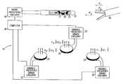
- FIG. 2schematically illustrates a system for tracking a probe, such as a catheter for medical use, according to a preferred embodiment of the present invention
- FIG. 3is a vector diagram illustrating a relation between position and parasitic components of a signal generated in the system of FIG. 2, according to a preferred embodiment of the present invention.
- FIG. 4is a schematic flow chart showing a method for choosing frequencies to track the probe of the system of FIG. 2, according to a preferred embodiment of the present invention.
- FIG. 2schematically illustrates a system 10 for tracking a probe 20 , such as a catheter for medical use, according to a preferred embodiment of the present invention.
- a probe 20such as a catheter for medical use
- FIG. 2schematically illustrates a system 10 for tracking a probe 20 , such as a catheter for medical use, according to a preferred embodiment of the present invention.
- System 10comprises a plurality of radiator coils 22 , 24 and 26 .
- Each frequency set ⁇ 1 ⁇ , ⁇ 2 ⁇ and ⁇ 3 ⁇comprises a plurality of individual frequencies.
- Typical values of frequencies f i in sets ⁇ 1 ⁇ , ⁇ 2 ⁇ and ⁇ 3 ⁇comprise frequencies in the range 100 Hz-20 kHz.
- System 10further comprises substantially similar variable frequency driver circuitry 30 , 32 and 33 , coupled to each of the radiator coils, which drive coils 22 , 24 and 26 at the respective sets of frequencies ⁇ 1 ⁇ , ⁇ 2 ⁇ and ⁇ 3 ⁇ .
- the sets of frequencies ⁇ 1 ⁇ , ⁇ 2 ⁇ and ⁇ 3 ⁇ at which the coils radiateare set by computer 36 .
- at least some of the frequencies of each driver circuitryare multiplexed together, and after acquisition the resulting signals are analyzed in signal processing circuitry 34 , as described in more detail below.
- the frequency of each driver circuitryis varied according to some other method known in the art, such as scanning the frequencies cyclically over time, and/or using one or more other methods of time multiplexing. Whichever method is used to vary the frequencies, at any instant in time a frequency radiated by a specific coil is set to be different from the frequency or frequencies radiated by all the other coils.
- the probeincludes sensor coils 27 , 28 and 29 , which generate electrical current signals in response to the magnetic fields. At any instant in time these signals comprise components of the specific frequencies ⁇ 1 ⁇ , ⁇ 2 ⁇ and ⁇ 3 ⁇ being generated, whose respective amplitudes are dependent on the position and orientation of probe 20 .
- the signals generated by sensor coils 27 , 28 and 29are preferably received and processed by signal processing circuitry 34 and then used by computer 36 to calculate position and orientation coordinates of probe 20 .
- FIG. 2shows three radiator coils 22 , 24 and 26 and three sensor coils 27 , 28 and 29 in a probe 20 . It will be understood, however, that the present invention is equally applicable to tracking systems comprising one, two, four or more radiator coils and one, two or more sensor coils. For example, the present invention applies to a single axis system comprising one sensor coil, in which case the system most preferably comprises nine radiator coils.
- the signals generated by sensor coils 27 , 28 and 29 at any of frequencies ⁇ 1 ⁇are proportional to the amplitude of the time derivative of the projection of field ⁇ right arrow over (H) ⁇ 1 at probe 20 along the respective axes of the sensor coils.
- the signals generated at any of frequencies ⁇ 2 ⁇ and ⁇ 3 ⁇are similarly proportional to the projections of ⁇ right arrow over (H) ⁇ 2 and ⁇ right arrow over (H) ⁇ 3 .
- Parasitic effects that may arise due to mutual inductance among the radiator coilsare preferably substantially eliminated, as disclosed, for example, in PCT patent application no. PCT/IL/00100, filed Mar. 18, 1997, which is assigned to the assignee of the present patent application, and whose disclosure is incorporated herein by reference.
- the sensor coil signals due to the respective radiator coil fieldmay be directly related to the sensor coil's distance from and orientation relative to the radiator coil. It will also be appreciated that in the absence of parasitic magnetic fields, such as will be described below, the phase of the signal at each specific frequency comprised in ⁇ 1 ⁇ , ⁇ 2 ⁇ and ⁇ 3 ⁇ is substantially constant relative to the phase of the magnetic field generated by radiator coils 22 , 24 , 26 , and depends on the position and orientation of sensor coils 27 , 28 , 29 .
- a metal or magnetic field-responsive articlefor example a surgical tool 40
- the articlewill generally receive energy from unperturbed fields ⁇ right arrow over (H) ⁇ 1 , ⁇ right arrow over (H) ⁇ 2 and ⁇ right arrow over (H) ⁇ 3 , and re-radiate perturbing parasitic magnetic fields, ⁇ right arrow over (H) ⁇ ′ 1 , ⁇ right arrow over (H) ⁇ ′ 2 and ⁇ right arrow over (H) ⁇ ′ 3 , at the specific frequencies from sets ⁇ 1 ⁇ , ⁇ 2 ⁇ and ⁇ 3 ⁇ which are being generated.
- phase angles ⁇ 1 ′, ⁇ 2 ′ and ⁇ 3 ′respectively.
- the phases and amplitudes of the parasitic fieldsgenerally depend on properties of tool 40 , including its dielectric constant, magnetic permeability, geometrical shape and orientation relative to the radiator coils.
- the phases and amplitudes of the parasitic fieldsare also a function of the specific frequencies being generated.
- FIG. 3is a vector diagram illustrating a relation between the position and parasitic signal components, for radiation from radiator coil 22 at sensor coil 27 , according to a preferred embodiment of the present invention.
- Coil 27generates a set of frequencies, responsive to the frequencies generated by radiator coils 22 , 24 and 26 , which are transferred to signal processing circuitry 34 .
- Circuitry 34separates the received signal into constituent frequencies, and recovers the amplitude and phase of each frequency, which are used as described hereinbelow with reference to FIG. 3 .
- sensor coil 27although it will be appreciated that sensor coils 28 , and 29 behave substantially as coil 27 .
- Signal vector 50having an amplitude
- Vector 50is the vector sum of position signal component vector 52 and parasitic signal component vector 54 .
- Vectors 50 , 52 , and 54are referenced in phase to a current I ⁇ in coil 27 .
- Position signal component 52has amplitude A ⁇ and a substantially constant baseline phase ⁇ ⁇ at frequency ⁇ .
- parasitic signal component 54has a phase shift from the baseline of ⁇ ⁇ ′ and an amplitude A ⁇ ′.
- the following explanationconsiders one specific frequency, herein termed ⁇ , although it will be appreciated that the explanation applies to all frequencies generated in coil 27 .
- the total combined signal M ⁇ received from sensor coil 27including both position and parasitic signal components may generally be expressed as:
- ⁇ overscore (A) ⁇ ⁇ and ⁇ overscore (A′) ⁇ ⁇are the phasors of the position signal component and the parasitic signal component respectively, at frequency ⁇ .
- signal processing circuitry 34 and computer 36detect and record baseline phases ⁇ ⁇ for all different frequencies received from sensor coils 27 , 28 and 29 , or for other systems described hereinabove such as the single axis system, in the absence of any metal or other interfering magnetic field-responsive objects in the vicinity of probe 20 .
- undisturbed phases of the position signal componentsmay have been determined in advance for system 10 or are known based on the operation of the system.
- FIG. 4is a schematic flow chart showing a method for choosing frequencies to track probe 20 , according to a preferred embodiment of the present invention.
- the following descriptionrefers only to radiator coil 22 and sensor coil 27 , but it will be understood that the method shown in FIG. 4 applies to any combination of a radiator coil and a sensor coil in system 10 .
- a baseline phase value ⁇ ⁇is measured by circuitry 34 from the voltages and currents induced in coil 27 .
- the baseline phase value ⁇ ⁇is measured at each of the frequencies of ⁇ 1 ⁇ and each value is recorded in computer 36 .
- is measured and recorded for each frequency of ⁇ 1 ⁇ .
- equations (2a) and (2b)apply for frequency ⁇ applied to sensor coil 27 .
- values of A ⁇ , ⁇ ⁇ , A ⁇ ′ and ⁇ ⁇ ′vary.
- values of A ⁇ and A ⁇ ′are directly proportional to the current at which the specific radiator coil, assumed herein to be radiator coil 22 , generating the field is being driven and which sensor coil 27 is detecting.
- a ⁇⁇ A 0
- a ⁇ ′⁇ A 0 ′
- ⁇is a constant
- ⁇ 0is an arbitrary frequency in ⁇ 1 ⁇
- a 0 and A 0 ′are the amplitudes of the position and parasitic signal components at frequency ⁇ 0 .
- ⁇ ⁇ ′is linearly dependent on frequency co, so that
- ⁇is a constant, corresponding to a value of the derivative ⁇ ⁇ ⁇ ⁇ ⁇ ⁇ ⁇ ⁇ ⁇ ⁇ ⁇ ,
- ⁇ ⁇ ′is the parasitic phase
- ⁇ 0 ′is the position phase
- equation (2a)can be rewritten as:
- ⁇ overscore (M) ⁇ iis a phasor representing the measured field at ⁇ i ,
- ⁇ overscore (A) ⁇ iis a phasor representing the unperturbed field
- ⁇ overscore (A) ⁇ i ′is a phasor representing the perturbing field due to tool 40 .
- Equation (5a)can be rewritten as follows:
- Equation (5b)can also be rewritten:
- a 0 ′ and ⁇ 0 ′are the perturbing amplitude and phase, and A 0 is the unperturbed amplitude, at ⁇ 0 ,
- equation (5c)A 0 , a 0 ′, and ⁇ 0 ′ are unknown, and ⁇ i , ⁇ i , ⁇ , ⁇ 0 , and ⁇ i are known, or in the case of ⁇ may be found from one other frequency apart from ⁇ 0 and ⁇ i by using the graph of FIG. 1 relating permeability to frequency. Alternatively, ⁇ may be assumed to be unknown. Thus, if ⁇ overscore (M) ⁇ i is measured at four known separate frequencies, equation (5c) can be solved for A 0 , the position signal component.
- frequencies ⁇ 1 ⁇ , ⁇ 2 ⁇ and ⁇ 3 ⁇ in system 10comprise more than four separate frequencies, so that a plurality of values of A 0 can be determined, and a final value of A 0 calculated by one of the processes of averaging known in the art.
- equation (5c)may be adapted to comprise other parameters describing at least some A 0 , a 0 ′, and ⁇ 0 ′.
- values of A 0 and a 0 ′can be assumed to depend on frequency ⁇ in a linear or a non-linear manner, and appropriate constants can be included in equation (5c), as is known in the art.
Landscapes
- Health & Medical Sciences (AREA)
- Life Sciences & Earth Sciences (AREA)
- Engineering & Computer Science (AREA)
- Surgery (AREA)
- Public Health (AREA)
- Veterinary Medicine (AREA)
- Biomedical Technology (AREA)
- Heart & Thoracic Surgery (AREA)
- Medical Informatics (AREA)
- Molecular Biology (AREA)
- Animal Behavior & Ethology (AREA)
- General Health & Medical Sciences (AREA)
- Physics & Mathematics (AREA)
- Pathology (AREA)
- Human Computer Interaction (AREA)
- Nuclear Medicine, Radiotherapy & Molecular Imaging (AREA)
- Biophysics (AREA)
- General Physics & Mathematics (AREA)
- Oral & Maxillofacial Surgery (AREA)
- Robotics (AREA)
- Investigating Or Analyzing Materials By The Use Of Magnetic Means (AREA)
- Measurement Of Length, Angles, Or The Like Using Electric Or Magnetic Means (AREA)
- Surgical Instruments (AREA)
- External Artificial Organs (AREA)
- Superconductors And Manufacturing Methods Therefor (AREA)
- Radiation-Therapy Devices (AREA)
- Length Measuring Devices With Unspecified Measuring Means (AREA)
Abstract
Description
This application is a continuation-in-part of U.S. patent application No. 09/173,763 filed Oct. 15, 1998 now U.S. Pat. No. 6,147,480 which is incorporated herein by reference.
The present invention relates generally to non-contact tracking of objects using a magnetic field, and specifically to counteracting the effect of an intruding field-responsive article in the field.
Non-contact electromagnetic tracking systems are well known in the art, with a wide range of applications.
U.S. Pat. No. 5,391,199, to Ben-Haim, which is assigned to the assignee of the present application and whose disclosure is incorporated herein by reference, describes a system for generating three-dimensional location information regarding a medical probe or catheter. A sensor coil is placed in the catheter and generates signals in response to externally applied magnetic fields. The magnetic fields are generated by three radiator coils, fixed to an external reference frame in known, mutually spaced locations. The amplitudes of the signals generated in response to each of the radiator coil fields are detected and used to compute the location of the sensor coil. Each radiator coil is preferably driven by driver circuitry to generate a field at a known frequency, distinct from that of other radiator coils, so that the signals generated by the sensor coil may be separated by frequency into components corresponding to the different radiator coils.
PCT patent publication WO/96/05768, filed Jan. 24, 1995, which is assigned to the assignee of the present application and whose disclosure is incorporated herein by reference, describes a system that generates six-dimensional position and orientation information regarding the tip of a catheter. This system uses a plurality of sensor coils adjacent to a locatable site in the catheter, for example near its distal end, and a plurality of radiator coils fixed in an external reference frame. These coils generate signals in response to magnetic fields generated by the radiator coils, which signals allow for the computation of six location and orientation coordinates. As in the case of the '539 patent application described above, the radiator coils preferably operate simultaneously at different frequencies, for example at 1000, 2000 and 3000 Hz, respectively.
The above tracking systems rely on separation of position-responsive signals into components, most typically frequency components, wherein each such component is assumed to correspond uniquely to a single radiator coil, in a known position, radiating a magnetic field having a regular, well-defined spatial distribution. In practice, however, when a metal or other magnetically-responsive article is brought into the vicinity of the catheter or other object being tracked, the magnetic fields generated in this vicinity by the radiator coils are distorted. For example, the radiator coil's magnetic field may generate eddy currents in such an article, and the eddy currents will then cause a parasitic magnetic field to be radiated. Such parasitic fields and other types of distortion can lead to errors in determining the position of the object being tracked.
U.S. Pat. No. 5,767,669 to Hansen et al., whose disclosure is incorporated herein by reference, describes a method for subtracting eddy current distortions produced in a magnetic tracking system. The system utilizes pulsed magnetic fields from a plurality of generators, and the presence of eddy currents is detected by measuring rates of change of currents generated in sensor coils used for tracking. The eddy currents are compensated for by adjusting the duration of the magnetic pulses.
U.S. Pat. No. 4,945,305 to Blood, whose disclosure is incorporated herein by reference, describes a tracking system which avoids the problems of eddy currents by using pulsed DC magnetic fields. Sensors which are able to detect DC fields are used in the system, and eddy currents are detected and adjusted for by utilizing the decay characteristics and the amplitudes of the eddy currents.
European Patent Application EP 0964261A2, to Dumoulin, whose disclosure is incorporated herein by reference, describes systems for compensating for eddy currents in a tracking system using alternating magnetic field generators. In a first system the eddy currents are compensated for by first calibrating the system free from eddy currents, and then modifying the fields generated when the eddy currents are detected. In a second system the eddy currents are nullified by using one or more shielding coils placed near the generators.
FIG. 1 is a graph showing a relation of the permeability μ of a ferromagnetic material in a magnetic field vs. frequency f at which the field is being generated, as is known in the art. Permeability μ is a factor in the phase shift generated by the magnetic field. The graph applies to a change of the permeability μ of the ferromagnetic material, generated for an article wherein eddy currents are formed. The change reflects the phase shift in a sensor, caused by the article, vs. the frequency f As. is known in the art, additional factors affecting the phase shift are geometry of the article, and conductivity of the material. The graph shows a virtually linear change in permeability for small changes in frequency.
It is an object of some aspects of the present invention to provide methods and apparatus for non-contact tracking of an object in an energy field in the presence of an article which interferes with the field.
It is another object of some aspects of the present invention to provide methods and apparatus for minimizing the effect of an article which interferes with an energy field used for non-contact tracking of an object.
In a preferred embodiment of the present invention, an object tracking system comprises one or more sensor coils adjacent to a locatable point on an object being tracked, and one or more radiator coils, which generate alternating energy fields comprising magnetic fields, in a vicinity of the object when driven by respective alternating electrical currents. For each radiator coil, a frequency of its alternating electrical current is scanned through a plurality of values so that, at any specific time, each of the radiator coils radiates at a frequency which is different from the frequencies with which the other radiator coils are radiating.
The sensor coils generate electrical signals responsive to the magnetic fields, which signals are received by signal processing circuitry and analyzed by a computer or other processor. When a metal or other field-responsive article is in the vicinity of the object, the signals typically include position signal components responsive to the magnetic fields generated by the radiator coils at their respective instantaneous driving frequencies, and parasitic signal components responsive to parasitic magnetic fields generated due to the article. The parasitic components are typically equal in frequency to the instantaneous frequency of the driving frequency, but are shifted in phase, so that the effect at each sensor coil is to produce a combined signal having a phase and an amplitude which are shifted relative to the signal when no field-responsive article is present. The phase-shift is a function of the driving frequency, and so will vary as each driving frequency is scanned. The computer processes the combined signal to find which frequency produces a minimum phase-shift, and thus a minimum effect of the parasitic components, and this frequency is used to calculate the position of the object. Varying the driving frequency until the phase shift is a minimum is an effective method, not known in the art, for reducing the effect of field-responsive articles on the signal.
In preferred embodiments of the present invention, an alternative method is also used in order to find a value of the position signal, i.e., of the signal produced without interfering effects of the field-responsive article. Measurements of the value of the combined signal are made at a plurality of frequencies. The values obtained are used to solve a plurality of simultaneous equations comprising the position signal as one of the unknowns in the equations. Thus, varying the driving frequency enables the position signal to be determined in the presence of interfering signals from field-responsive articles.
The present invention relies on the fact that parasitic magnetic fields, generated by metal or other field-responsive articles that receive and re-radiate energy from a radiator coil magnetic field are typically at the same frequency as the radiator coil field, but are shifted in phase relative thereto. The phase shift and the amplitudes of the parasitic fields generally depend on properties of the article, including dielectric constant, magnetic permeability and geometrical shape.
However, both the phase shift and the amplitude of the parasitic fields can be assumed to be linearly dependent on the value of the frequency generating the parasitic field.
There is therefore provided, according to a preferred embodiment of the present invention, a method for tracking an object including:
producing an unperturbed energy field at a plurality of predetermined frequencies in the vicinity of the object;
determining a characteristic of a perturbing energy field induced responsive to the unperturbed field, due to introduction of an article responsive to the unperturbed field into the vicinity of the object;
receiving a plurality of resultant signals responsive to the unperturbed and perturbing energy fields generated at a location of the object after introduction of the article;
determining an optimal frequency for the unperturbed energy field from amongst the plurality of predetermined frequencies responsive to a parameter of the resultant signals; and
determining spatial coordinates of the object responsive to the resultant signal at the optimal frequency.
Preferably, producing the unperturbed energy field at the plurality of predetermined frequencies includes scanning the frequencies sequentially.
Further preferably, producing the unperturbed energy field at the plurality of predetermined frequencies includes multiplexing at least some of the frequencies.
Preferably, receiving the plurality of resultant signals includes:
measuring a baseline phase value φ107 of each of the plurality of resultant signals at the respective plurality of predetermined frequencies before introduction of the article; and
measuring a phase shift φωtotalat the respective plurality of predetermined frequencies after introduction of the article, so that the parameter comprises a term |φωtotal−φω| for each of the plurality of predetermined frequencies; and
wherein determining the optimal frequency includes determining a frequency ω at which |φωtotal−φω| is a minimum.
Preferably, determining spatial coordinates of the object includes determining spatial coordinates responsive to an amplitude of a signal |Mω| at the frequency ω.
Further preferably, determining spatial coordinates of the object includes determining spatial coordinates responsive to a phase of a signal Mω at the frequency ω.
Preferably, producing the energy fields includes producing magnetic fields. Preferably, receiving the signals includes receiving electrical signals which are generated responsive to the magnetic fields.
There is further provided, according to a preferred embodiment of the present invention, a method for tracking an object, including:
producing an unperturbed energy field comprising a plurality of predetermined frequencies in the vicinity of the object;
producing a perturbing energy field by introduction of an article responsive to the unperturbed field into the vicinity of the object;
receiving a respective plurality of signals responsive to the unperturbed and perturbing energy fields generated at a location of the object after introduction of the article; and
determining one or more factors conditional on spatial coordinates of the object responsive to the plurality of signals and the respective frequencies.
Preferably, determining the one or more factors includes:
assuming a phasor {overscore (A)}ω of a signal responsive to the unperturbed energy field and a phasor {overscore (A)}′ω of a signal responsive to the perturbing energy field to be directly proportional to a plurality of predetermined currents generating the fields; and
assuming a phase φω of the signal responsive to the unperturbed energy field and a phase φω′ of the signal responsive to the perturbing energy field to be linearly dependent on the plurality of predetermined frequencies.
Preferably, the plurality of frequencies includes at least four frequencies, and the one or more factors include the spatial coordinates of the object.
Preferably, receiving the plurality of signals comprises receiving at least four values of a signal Miat the at least four frequencies, and determining the one or more factors includes:
determining a value of a position signal amplitude A0, generated responsive to the unperturbed energy field, by substituting respective values of the signal Miinto an equation
wherein {overscore (M)}iis a phasor representing a measured field, {overscore (A)}iis a phasor representing the unperturbed field, ai′ represents an amplitude of the perturbing field, φi′ represents a phase of the perturbing field, and i represents at least four numbers respectively corresponding to the at least four frequencies, so as to generate at least four equations; and
solving the at least four equations for the position signal amplitude A0.
There is further provided, according to a preferred embodiment of the present invention, object tracking apparatus, comprising:
a radiator, which generates an energy field at a plurality of predetermined frequencies in the vicinity of the object;
a sensor, fixed to the object, which generates a plurality of signals responsive to the energy field and to an interfering article responsive to the energy field; and
signal processing circuitry, which receives the plurality of signals from the sensor and determines an optimal frequency for the energy field from amongst the plurality of predetermined frequencies responsive to a parameter of the signals, and which determines position coordinates of the object responsive to the signal at the optimal frequency.
Preferably, the radiator generates the energy field at the plurality of predetermined frequencies by scanning the frequencies sequentially.
Further preferably, the radiator generates the energy field at the plurality of predetermined frequencies by multiplexing at least some of the frequencies.
Preferably, the parameter includes a phase shift, and the optimal frequency includes the frequency where the phase shift is a minimum.
Preferably, the signal processing circuitry determines the position coordinates of the object responsive to an amplitude of one of the plurality of signals at the frequency where the phase shift is a minimum.
Preferably, the energy field includes a magnetic field.
Preferably, the plurality of signals include a plurality of electrical signals which are generated responsive to the magnetic field.
There is further provided, according to a preferred embodiment of the present invention, object tracking apparatus, including:
a radiator, which generates an energy field including a plurality of predetermined frequencies in the vicinity of the object;
a sensor, fixed to the object, which generates a respective plurality of signals responsive to the energy field and to an interfering article responsive to the energy field; and
signal processing circuitry, which receives the plurality of signals from the sensor and determines one or more factors conditional on spatial coordinates of the object responsive to the signals and their corresponding frequencies.
Preferably, the plurality of frequencies includes at least four frequencies, and wherein the one or more factors comprise the spatial coordinates of the object.
The present invention will be more fully understood from the following detailed description of the preferred embodiments thereof, taken together with the drawings, in which:
FIG. 1 is a graph showing a relation of the permeability μ of a ferromagnetic material in a magnetic field vs. frequency f at which the field is being generated, as is known in the art;
FIG. 2 schematically illustrates a system for tracking a probe, such as a catheter for medical use, according to a preferred embodiment of the present invention;
FIG. 3 is a vector diagram illustrating a relation between position and parasitic components of a signal generated in the system of FIG. 2, according to a preferred embodiment of the present invention; and
FIG. 4 is a schematic flow chart showing a method for choosing frequencies to track the probe of the system of FIG. 2, according to a preferred embodiment of the present invention.
Reference is now made to FIG. 2, which schematically illustrates asystem 10 for tracking aprobe 20, such as a catheter for medical use, according to a preferred embodiment of the present invention. The operation of systems generally similar tosystem 10 are described in detail in the above-mentioned U.S. patent application Ser. No. 09/173,763, U.S. Pat. No. 5,391,199, and PCT patent publication WO/96/05768, whose disclosures are assigned to the assignee of the present invention, and which are incorporated herein by reference.System 10 comprises a plurality of radiator coils22,24 and26. These coils generate respective magnetic fields H, H and {right arrow over (H)}3, at respective sets of frequencies {ω1}, {ω2} and {ω3}, in the vicinity ofprobe 20. Each frequency set {ω1}, {ω2} and {ω3}, comprises a plurality of individual frequencies. Most preferably, each of frequencies fiin sets {ω1}, {ω2} and {ω3} is simply divisible by a common frequency f0, i.e., fi=k1f0where k1is a whole number. In this case, a sampling period ΔT circuitry receiving radiated signals, which signals are explained in more detail hereinbelow, is preferably given by the following equation:

where k2represents a whole number.
Typical values of frequencies fiin sets {ω1}, {ω2} and {ω3} comprise frequencies in the range 100 Hz-20 kHz.
The probe includes sensor coils27,28 and29, which generate electrical current signals in response to the magnetic fields. At any instant in time these signals comprise components of the specific frequencies {ω1}, {ω2} and {ω3} being generated, whose respective amplitudes are dependent on the position and orientation ofprobe 20. The signals generated bysensor coils signal processing circuitry 34 and then used bycomputer 36 to calculate position and orientation coordinates ofprobe 20.
FIG. 2 shows threeradiator coils sensor coils probe 20. It will be understood, however, that the present invention is equally applicable to tracking systems comprising one, two, four or more radiator coils and one, two or more sensor coils. For example, the present invention applies to a single axis system comprising one sensor coil, in which case the system most preferably comprises nine radiator coils.
In the absence of parasitic effects, the signals generated bysensor coils probe 20 along the respective axes of the sensor coils. The signals generated at any of frequencies {ω2} and {ω3} are similarly proportional to the projections of {right arrow over (H)}2and {right arrow over (H)}3. Parasitic effects that may arise due to mutual inductance among the radiator coils are preferably substantially eliminated, as disclosed, for example, in PCT patent application no. PCT/IL/00100, filed Mar. 18, 1997, which is assigned to the assignee of the present patent application, and whose disclosure is incorporated herein by reference.
Since the direction and amplitude of the magnetic field due to any one of radiator coils22,24 and26 can be calculated easily using methods known in the art, the sensor coil signals due to the respective radiator coil field may be directly related to the sensor coil's distance from and orientation relative to the radiator coil. It will also be appreciated that in the absence of parasitic magnetic fields, such as will be described below, the phase of the signal at each specific frequency comprised in {ω1}, {ω2} and {ω3} is substantially constant relative to the phase of the magnetic field generated byradiator coils
As shown in FIG. 2, however, when a metal or magnetic field-responsive article, for example asurgical tool 40, is introduced into the vicinity ofprobe 20, the article will generally receive energy from unperturbed fields {right arrow over (H)}1, {right arrow over (H)}2and {right arrow over (H)}3, and re-radiate perturbing parasitic magnetic fields, {right arrow over (H)}′1, {right arrow over (H)}′2and {right arrow over (H)}′3, at the specific frequencies from sets {ω1}, {ω2} and {ω3} which are being generated. Generally the phases of the parasitic fields will be shifted relative to the radiator coil fields by phase angles φ1′, φ2′ and φ3′, respectively. The phases and amplitudes of the parasitic fields generally depend on properties oftool 40, including its dielectric constant, magnetic permeability, geometrical shape and orientation relative to the radiator coils. The phases and amplitudes of the parasitic fields are also a function of the specific frequencies being generated.
FIG. 3 is a vector diagram illustrating a relation between the position and parasitic signal components, for radiation fromradiator coil 22 atsensor coil 27, according to a preferred embodiment of the present invention.Coil 27 generates a set of frequencies, responsive to the frequencies generated byradiator coils processing circuitry 34.Circuitry 34 separates the received signal into constituent frequencies, and recovers the amplitude and phase of each frequency, which are used as described hereinbelow with reference to FIG.3. In the interests of simplicity, unless indicated otherwise the following explanation refers tosensor coil 27, although it will be appreciated that sensor coils28, and29 behave substantially ascoil 27.
The total combined signal Mω received fromsensor coil 27, including both position and parasitic signal components may generally be expressed as:
so that the amplitude |Mω| is given by
wherein {overscore (A)}ω and {overscore (A′)}ω are the phasors of the position signal component and the parasitic signal component respectively, at frequency ω.
It will be observed in equation (2b) and from FIG. 3 that for each of the signal frequency components |Mω|, the superposition of the parasitic signal component will cause a phase shift in the total detected signal, relative to the signal phase in the absence ofmetal tool 40, given by:

In preferred embodiments of the present invention,signal processing circuitry 34 andcomputer 36 detect and record baseline phases φω for all different frequencies received from sensor coils27,28 and29, or for other systems described hereinabove such as the single axis system, in the absence of any metal or other interfering magnetic field-responsive objects in the vicinity ofprobe 20. Alternatively, undisturbed phases of the position signal components may have been determined in advance forsystem 10 or are known based on the operation of the system. Whenmetal tool 40 is introduced into the vicinity ofprobe 20, the phase shift due to the parasitic components engendered thereby in the signals is measured at each separate frequency.
FIG. 4 is a schematic flow chart showing a method for choosing frequencies to trackprobe 20, according to a preferred embodiment of the present invention. For simplicity, the following description refers only toradiator coil 22 andsensor coil 27, but it will be understood that the method shown in FIG. 4 applies to any combination of a radiator coil and a sensor coil insystem 10. In an initialization phase a baseline phase value φω is measured bycircuitry 34 from the voltages and currents induced incoil 27. The baseline phase value φω is measured at each of the frequencies of {ω1} and each value is recorded incomputer 36. During an operation phase the value of total and the absolute value of the difference, |φωtotal−φω|, is measured and recorded for each frequency of {ω1}. In the event that the absolute difference is not equal to zero, indicating that a parasitic signal component due totool 40 is present,computer 36 selects the frequency having the smallest absolute difference. This frequency is used when evaluating |Mω| in equation (2b). It will be appreciated that applying the method described hereinabove to all combinations of radiator coils and sensor coils insystem 10 enables a complete determination of the position and orientation ofprobe 20.
As stated hereinabove, equations (2a) and (2b) apply for frequency ω applied tosensor coil 27. As the frequency ω is varied, values of Aω, φω, Aω′ and φω′ vary. As is known in the art, values of Aω and Aω′ are directly proportional to the current at which the specific radiator coil, assumed herein to beradiator coil 22, generating the field is being driven and whichsensor coil 27 is detecting. Thus Aω=βA0, and Aω′=βA0′ where β is a constant, ω0is an arbitrary frequency in {ω1}, and A0and A0′ are the amplitudes of the position and parasitic signal components at frequency ω0. Also, for small variations of frequency ω, φω′ is linearly dependent on frequency co, so that
where
Δω=ω−ω0,

φω′ is the parasitic phase and
φ0′ is the position phase.
At a particular frequency ωi, equation (2a) can be rewritten as:
where
{overscore (M)}iis a phasor representing the measured field at ωi,
{overscore (A)}iis a phasor representing the unperturbed field, and
{overscore (A)}i′ is a phasor representing the perturbing field due totool 40.
Equation (5a) can be rewritten as follows:
where ai′ and φi′ are the perturbing amplitude and phase at ωi.
Equation (5b) can also be rewritten:
where
a0′ and φ0′ are the perturbing amplitude and phase, and A0is the unperturbed amplitude, at ω0,

In equation (5c) A0, a0′, and φ0′ are unknown, and φi, βi, γ, ω0, and ωiare known, or in the case of γ may be found from one other frequency apart from ω0and ωiby using the graph of FIG. 1 relating permeability to frequency. Alternatively, γ may be assumed to be unknown. Thus, if {overscore (M)}iis measured at four known separate frequencies, equation (5c) can be solved for A0, the position signal component. Most preferably, frequencies {ω1}, {ω2} and {ω3} insystem 10 comprise more than four separate frequencies, so that a plurality of values of A0can be determined, and a final value of A0calculated by one of the processes of averaging known in the art. Alternatively or additionally, when frequencies {ω1}, {ω2} and {ω3} insystem 10 comprise more than four separate frequencies, equation (5c) may be adapted to comprise other parameters describing at least some A0, a0′, and φ0′. For example, values of A0and a0′ can be assumed to depend on frequency ω in a linear or a non-linear manner, and appropriate constants can be included in equation (5c), as is known in the art.
It will thus be appreciated that by varying the excitation frequency of each radiator coil, and measuring the total signal generated in each sensor coil at these frequencies, the position component of the signal can be determined regardless of the presence of parasitic components. It will also be appreciated that varying the excitation frequency of each radiator coil by a plurality of frequencies, wherein the plurality is fewer than four, will give useful information regarding factors associated with tracking objects in the presence of interfering articles.
It will further be appreciated that the preferred embodiments described above are cited by way of example, and that the present invention is not limited to what has been particularly shown and described hereinabove. Rather, the scope of the present invention includes both combinations and subcombinations of the various features described hereinabove, as well as variations and modifications thereof which would occur to persons skilled in the art upon reading the foregoing description and which are not disclosed in the prior art.
Claims (19)
1. A method for tracking an object, comprising:
producing an unperturbed energy field at a plurality of predetermined frequencies in the vicinity of the object;
measuring a baseline phase value φω of each of the plurality of resultant signals at the respective plurality of predetermined frequencies before introduction of the article;
determining a characteristic of a perturbing energy field induced responsive to the unperturbed field, due to introduction of an article responsive to the unperturbed field into the vicinity of the object;
receiving a plurality of resultant signals responsive to the unperturbed and perturbing energy fields generated at a location of the object after introduction of the article;
measuring a phase shift φωtotalat the respective plurality of predetermined frequencies after introduction of the article, so that the parameter comprises a term |φωtotal−φω| for each of the plurality of predetermined frequencies;
determining an optimal frequency for the unperturbed energy field from amongst the plurality of predetermined frequencies responsive to a parameter of the resultant signals by determining a frequency ω at which |φωtotal−φω| a is a minimum; and
determining spatial coordinates of the object responsive to the resultant signal at the optimal frequency.
2. A method according toclaim 1 , wherein producing the unperturbed energy field at the plurality of predetermined frequencies comprises scanning the frequencies sequentially.
3. A method according toclaim 1 , wherein producing the unperturbed energy field at the plurality of predetermined frequencies comprises multiplexing at least some of the frequencies.
4. A method according toclaim 1 , wherein determining spatial coordinates of the object comprises determining spatial coordinates responsive to an amplitude of a signal |Mω| at the frequency ω.
5. A method according toclaim 1 , wherein determining spatial coordinates of the object comprises determining spatial coordinates responsive to a phase of a signal Mω at the frequency ω.
6. A method according toclaim 1 , wherein producing the energy fields comprises producing magnetic fields.
7. A method according toclaim 6 , wherein receiving the signals comprises receiving electrical signals which are generated responsive to the magnetic fields.
8. A method for tracking an object, comprising:
producing an unperturbed energy field comprising a plurality of predetermined frequencies in the vicinity of the object;
producing a perturbing energy field by introduction of an article responsive to the unperturbed field into the vicinity of the object;
receiving a respective plurality of signals responsive to the unperturbed and perturbing energy fields generated at a location of the object after introduction of the article;
determining one or more factors conditional on spatial coordinates of the object responsive to the plurality of signals and the respective frequencies by assuming a phasor {overscore (A)}ω of a signal responsive to the unperturbed energy field and a phasor {overscore (A)}′ω of a signal responsive to the perturbing energy field to be directly proportional to a plurality of predetermined currents generating the fields; and
assuming a phase φω of the signal responsive to the unperturbed energy field and a phase φω of the signal responsive to the perturbing energy field to be linearly dependent on the plurality of predetermined frequencies.
9. A method according toclaim 8 , wherein the plurality of frequencies comprises at least four frequencies, and wherein the one or more factors comprise the spatial coordinates of the object.
10. A method according toclaim 9 , wherein receiving the plurality of signals comprises receiving at least four values of a signal Miat the at least four frequencies, and wherein determining the one or more factors comprises:
determining a value of a position signal amplitude A0, generated responsive to the unperturbed energy field, by substituting respective values of the signal Miinto an equation
wherein {overscore (M)}iis a phasor representing a measured field, {overscore (A)}iis a phasor representing the unperturbed field, ai′ represents an amplitude of the perturbing field, φi′ represents a phase of the perturbing field, and i represents at least four numbers respectively corresponding to the at least four frequencies, so as to generate at least four equations; and
solving the at least four equations for the position signal amplitude A0.
11. Object tracking apparatus, comprising:
a radiator, which generates an energy field at a plurality of predetermined frequencies in the vicinity of the object;
a sensor, fixed to the object, which generates a plurality of signals responsive to the energy field and to an interfering article responsive to the energy field; and
signal processing circuitry, which receives the plurality of signals from the sensor and determines an optimal frequency for the energy field from amongst the plurality of predetermined frequencies responsive to a parameter of the signals by measuring a baseline phase value φω of each of the plurality of resultant signals at the respective plurality of predetermined frequencies before introduction of the article; and measuring a phase shift φωtotalat the respective plurality of predetermined frequencies after introduction of the article, so that the parameter comprises a term |φωtotal−φω| for each of the plurality of predetermined frequencies, and which determines position coordinates of the object responsive of the object responsive to the signal at the optimal frequency by determining a frequency ω at which |φωtotal−φω| is a minimum.
12. Apparatus according toclaim 11 , wherein the radiator generates the energy field at the plurality of predetermined frequencies by scanning the frequencies sequentially.
13. Apparatus according toclaim 11 , wherein the radiator generates the energy field at the plurality of predetermined frequencies by multiplexing at least some of the frequencies.
14. Apparatus according toclaim 11 , wherein the parameter comprises a phase shift, and wherein the optimal frequency comprises the frequency where the phase shift is a minimum.
15. Apparatus according toclaim 14 , wherein the signal processing circuitry determines the position coordinates of the object responsive to an amplitude of one of the plurality of signals at the frequency where the phase shift is a minimum.
16. Apparatus according toclaim 11 , wherein the energy field comprises a magnetic field.
17. Apparatus according toclaim 16 , wherein the plurality of signals comprise a plurality of electrical signals which are generated responsive to the magnetic field.
18. Object tracking apparatus, comprising:
a radiator, which generates an energy field comprising a plurality of predetermined frequencies in the vicinity of the object;
a sensor, fixed to the object, which generates a respective plurality of signals responsive to the energy field and to an interfering article responsive to the energy field; and
signal processing circuitry, which receives the plurality of signals from the sensor and determines one or more factors conditional on spatial coordinates of the object responsive to the signals and their corresponding frequencies by assuming a phasor {overscore (A)}ω of a signal responsive to the unperturbed energy field and a phasor {overscore (A′)}ω of a signal responsive to the perturbing energy field to be directly proportional to a plurality of predetermined currents generating the fields; and
assuming a phase φω of the signal responsive to the unperturbed energy field and a phase φω′ of the signal responsive to the perturbing energy field to be linearly dependent on the plurality of predetermined frequencies.
19. Apparatus according toclaim 18 , wherein the plurality of frequencies comprises at least four frequencies, and wherein the one or more factors comprise the spatial coordinates of the object.
Priority Applications (10)
| Application Number | Priority Date | Filing Date | Title |
|---|---|---|---|
| US09/702,973US6373240B1 (en) | 1998-10-15 | 2000-10-31 | Metal immune system for tracking spatial coordinates of an object in the presence of a perturbed energy field |
| IL146216AIL146216A (en) | 2000-10-31 | 2001-10-29 | Metal immune system |
| CA2360598ACA2360598C (en) | 2000-10-31 | 2001-10-29 | Metal immune system |
| AT01309190TATE506009T1 (en) | 2000-10-31 | 2001-10-30 | DEVICE FOR LOCATING AN OBJECT, IN PARTICULAR A CATHETER, USING ENERGY FIELDS |
| EP05076761.5AEP1604610B1 (en) | 2000-10-31 | 2001-10-30 | Method and apparatus for tracking an object, in particular a catheter, using energy fields |
| EP01309190AEP1203560B1 (en) | 2000-10-31 | 2001-10-30 | Apparatus for tracking an object, in particular a catheter, using energy fields |
| DE60144463TDE60144463D1 (en) | 2000-10-31 | 2001-10-30 | Device for locating an object, in particular a catheter by means of energy fields |
| AU85546/01AAU776644B2 (en) | 2000-10-31 | 2001-10-31 | Metal immune system for tracking spatial coordinates of an object in the presence of a perturbed energy field |
| JP2001334426AJP2002236010A (en) | 2000-10-31 | 2001-10-31 | Metal immune system |
| KR1020010067515AKR100830853B1 (en) | 2000-10-31 | 2001-10-31 | Metal immune system |
Applications Claiming Priority (2)
| Application Number | Priority Date | Filing Date | Title |
|---|---|---|---|
| US09/173,763US6147480A (en) | 1997-10-23 | 1998-10-15 | Detection of metal disturbance |
| US09/702,973US6373240B1 (en) | 1998-10-15 | 2000-10-31 | Metal immune system for tracking spatial coordinates of an object in the presence of a perturbed energy field |
Related Parent Applications (1)
| Application Number | Title | Priority Date | Filing Date |
|---|---|---|---|
| US09/173,763Continuation-In-PartUS6147480A (en) | 1997-10-23 | 1998-10-15 | Detection of metal disturbance |
Publications (1)
| Publication Number | Publication Date |
|---|---|
| US6373240B1true US6373240B1 (en) | 2002-04-16 |
Family
ID=24823401
Family Applications (1)
| Application Number | Title | Priority Date | Filing Date |
|---|---|---|---|
| US09/702,973Expired - LifetimeUS6373240B1 (en) | 1998-10-15 | 2000-10-31 | Metal immune system for tracking spatial coordinates of an object in the presence of a perturbed energy field |
Country Status (9)
| Country | Link |
|---|---|
| US (1) | US6373240B1 (en) |
| EP (2) | EP1203560B1 (en) |
| JP (1) | JP2002236010A (en) |
| KR (1) | KR100830853B1 (en) |
| AT (1) | ATE506009T1 (en) |
| AU (1) | AU776644B2 (en) |
| CA (1) | CA2360598C (en) |
| DE (1) | DE60144463D1 (en) |
| IL (1) | IL146216A (en) |
Cited By (121)
| Publication number | Priority date | Publication date | Assignee | Title |
|---|---|---|---|---|
| US20020107445A1 (en)* | 1999-03-11 | 2002-08-08 | Assaf Govari | Implantable and insertable passive tags |
| US20030004411A1 (en)* | 1999-03-11 | 2003-01-02 | Assaf Govari | Invasive medical device with position sensing and display |
| US20030018246A1 (en)* | 1999-03-11 | 2003-01-23 | Assaf Govari | Guidance of invasive medical procedures using implantable tags |
| US20030023161A1 (en)* | 1999-03-11 | 2003-01-30 | Assaf Govari | Position sensing system with integral location pad and position display |
| WO2004004564A1 (en)* | 2002-07-04 | 2004-01-15 | Surgi-Wire, S.L. | Equipment for the detection of surgical products |
| US20040239314A1 (en)* | 2003-05-29 | 2004-12-02 | Assaf Govari | Hysteresis assessment for metal immunity |
| US20040254453A1 (en)* | 2003-05-29 | 2004-12-16 | Assaf Govari | Dynamic metal immunity by hysteresis |
| US20050024043A1 (en)* | 2003-07-31 | 2005-02-03 | Assaf Govari | Detection of metal disturbance in a magnetic tracking system |
| US20050154286A1 (en)* | 2004-01-02 | 2005-07-14 | Neason Curtis G. | System and method for receiving and displaying information pertaining to a patient |
| US20050154282A1 (en)* | 2003-12-31 | 2005-07-14 | Wenguang Li | System and method for registering an image with a representation of a probe |
| US20050154279A1 (en)* | 2003-12-31 | 2005-07-14 | Wenguang Li | System and method for registering an image with a representation of a probe |
| US20050154285A1 (en)* | 2004-01-02 | 2005-07-14 | Neason Curtis G. | System and method for receiving and displaying information pertaining to a patient |
| WO2005086062A2 (en) | 2004-03-05 | 2005-09-15 | Depuy International Limited | Registration methods and apparatus |
| WO2005084572A2 (en) | 2004-03-05 | 2005-09-15 | Depuy International Ltd | Implantable marker, instruments and methods |
| WO2005084544A1 (en) | 2004-03-05 | 2005-09-15 | Depuy International Ltd | Orthopaedic monitoring system, methods and apparatus |
| US20050209524A1 (en)* | 2004-03-10 | 2005-09-22 | General Electric Company | System and method for receiving and storing information pertaining to a patient |
| US20050222509A1 (en)* | 2004-04-02 | 2005-10-06 | General Electric Company | Electrophysiology system and method |
| US20050228251A1 (en)* | 2004-03-30 | 2005-10-13 | General Electric Company | System and method for displaying a three-dimensional image of an organ or structure inside the body |
| US20050228252A1 (en)* | 2004-04-02 | 2005-10-13 | General Electric Company | Electrophysiology system and method |
| US20050245821A1 (en)* | 2004-03-05 | 2005-11-03 | Assaf Govari | Position sensing system for orthopedic applications |
| EP1693010A1 (en) | 2005-02-22 | 2006-08-23 | Depuy orthopädie GmbH | A surgical instrument combination for accurate positioning of a cutting plane |
| EP1693011A1 (en) | 2005-02-22 | 2006-08-23 | Depuy International Limited | An instrument for implanting a sensor |
| WO2006090141A1 (en) | 2005-02-22 | 2006-08-31 | Depuy International Limited | A probe for use in computer assisted surgery |
| US20060241394A1 (en)* | 2005-02-22 | 2006-10-26 | Assaf Govari | Resolution of magnetic dipole ambiguity in position tracking measurements |
| US20070085528A1 (en)* | 2005-10-19 | 2007-04-19 | Assaf Govari | Metal immunity in a reverse magnetic system |
| US20070161888A1 (en)* | 2005-12-30 | 2007-07-12 | Sherman Jason T | System and method for registering a bone of a patient with a computer assisted orthopaedic surgery system |
| US20070167703A1 (en)* | 2005-12-30 | 2007-07-19 | Sherman Jason T | Method for determining a position of a magnetic source |
| US20070163367A1 (en)* | 2005-12-30 | 2007-07-19 | Sherman Jason T | Magnetic sensor array |
| US20070167741A1 (en)* | 2005-12-30 | 2007-07-19 | Sherman Jason T | Apparatus and method for registering a bone of a patient with a computer assisted orthopaedic surgery system |
| US20080033282A1 (en)* | 2006-08-07 | 2008-02-07 | Bar-Tal Meir | Distortion-immune position tracking using redundant measurements |
| EP1891895A1 (en) | 2006-08-21 | 2008-02-27 | Biosense Webster, Inc. | Distortion-immune position tracking using frequency extrapolation |
| US20080118135A1 (en)* | 2006-11-10 | 2008-05-22 | Superdimension, Ltd. | Adaptive Navigation Technique For Navigating A Catheter Through A Body Channel Or Cavity |
| US20080154127A1 (en)* | 2006-12-21 | 2008-06-26 | Disilvestro Mark R | Method and system for registering a bone of a patient with a computer assisted orthopaedic surgery system |
| US20080167639A1 (en)* | 2007-01-08 | 2008-07-10 | Superdimension Ltd. | Methods for localized intra-body treatment of tissue |
| US20080243429A1 (en)* | 2007-03-29 | 2008-10-02 | Kenichiro Yoshino | Three-dimensional position-measuring apparatus |
| US20080294036A1 (en)* | 2007-04-23 | 2008-11-27 | Device Evolutions, Llc | Surgical Metal Detection Apparatus and Methods |
| US20090156951A1 (en)* | 2007-07-09 | 2009-06-18 | Superdimension, Ltd. | Patient breathing modeling |
| US7575550B1 (en) | 1999-03-11 | 2009-08-18 | Biosense, Inc. | Position sensing based on ultrasound emission |
| US20090292309A1 (en)* | 2008-05-20 | 2009-11-26 | Michael Maschke | System and workflow for diagnosing and treating septum defects |
| US20100008555A1 (en)* | 2008-05-15 | 2010-01-14 | Superdimension, Ltd. | Automatic Pathway And Waypoint Generation And Navigation Method |
| US20100034449A1 (en)* | 2008-06-06 | 2010-02-11 | Superdimension, Ltd. | Hybrid Registration Method |
| US7809421B1 (en) | 2000-07-20 | 2010-10-05 | Biosense, Inc. | Medical system calibration with static metal compensation |
| US20110050216A1 (en)* | 2009-09-01 | 2011-03-03 | Adidas Ag | Method And System For Limiting Interference In Magnetometer Fields |
| US7945309B2 (en) | 2002-11-22 | 2011-05-17 | Biosense, Inc. | Dynamic metal immunity |
| US7966058B2 (en) | 2003-12-31 | 2011-06-21 | General Electric Company | System and method for registering an image with a representation of a probe |
| US7998062B2 (en) | 2004-03-29 | 2011-08-16 | Superdimension, Ltd. | Endoscope structures and techniques for navigating to a target in branched structure |
| US20110206253A1 (en)* | 2010-02-01 | 2011-08-25 | Superdimension, Ltd. | Region-Growing Algorithm |
| WO2011144421A1 (en)* | 2010-05-21 | 2011-11-24 | Siemens Aktiengesellschaft | Electromagnetic position measurement with multi-frequency marker |
| US8437833B2 (en) | 2008-10-07 | 2013-05-07 | Bard Access Systems, Inc. | Percutaneous magnetic gastrostomy |
| US8473032B2 (en) | 2008-06-03 | 2013-06-25 | Superdimension, Ltd. | Feature-based registration method |
| US8478382B2 (en) | 2008-02-11 | 2013-07-02 | C. R. Bard, Inc. | Systems and methods for positioning a catheter |
| DE102004021053B4 (en)* | 2003-05-12 | 2013-07-04 | Vacuumschmelze Gmbh & Co. Kg | Magnetic field sensor means |
| US8512256B2 (en) | 2006-10-23 | 2013-08-20 | Bard Access Systems, Inc. | Method of locating the tip of a central venous catheter |
| US8611984B2 (en) | 2009-04-08 | 2013-12-17 | Covidien Lp | Locatable catheter |
| US8663088B2 (en) | 2003-09-15 | 2014-03-04 | Covidien Lp | System of accessories for use with bronchoscopes |
| US8764725B2 (en) | 2004-02-09 | 2014-07-01 | Covidien Lp | Directional anchoring mechanism, method and applications thereof |
| US8774907B2 (en) | 2006-10-23 | 2014-07-08 | Bard Access Systems, Inc. | Method of locating the tip of a central venous catheter |
| US8781555B2 (en) | 2007-11-26 | 2014-07-15 | C. R. Bard, Inc. | System for placement of a catheter including a signal-generating stylet |
| US8784336B2 (en) | 2005-08-24 | 2014-07-22 | C. R. Bard, Inc. | Stylet apparatuses and methods of manufacture |
| US8801693B2 (en) | 2010-10-29 | 2014-08-12 | C. R. Bard, Inc. | Bioimpedance-assisted placement of a medical device |
| US8849382B2 (en) | 2007-11-26 | 2014-09-30 | C. R. Bard, Inc. | Apparatus and display methods relating to intravascular placement of a catheter |
| US8907660B2 (en) | 2009-12-22 | 2014-12-09 | Commissariat A L'energie Atomique Et Aux Energies Alternatives | Method and device for identifying a subset of measurements, method and system for locating an object, recording medium for these methods |
| US8905920B2 (en) | 2007-09-27 | 2014-12-09 | Covidien Lp | Bronchoscope adapter and method |
| US8932207B2 (en) | 2008-07-10 | 2015-01-13 | Covidien Lp | Integrated multi-functional endoscopic tool |
| USD724745S1 (en) | 2011-08-09 | 2015-03-17 | C. R. Bard, Inc. | Cap for an ultrasound probe |
| US9055881B2 (en) | 2004-04-26 | 2015-06-16 | Super Dimension Ltd. | System and method for image-based alignment of an endoscope |
| US9125578B2 (en) | 2009-06-12 | 2015-09-08 | Bard Access Systems, Inc. | Apparatus and method for catheter navigation and tip location |
| US9211107B2 (en) | 2011-11-07 | 2015-12-15 | C. R. Bard, Inc. | Ruggedized ultrasound hydrogel insert |
| USD754357S1 (en) | 2011-08-09 | 2016-04-19 | C. R. Bard, Inc. | Ultrasound probe head |
| US9339206B2 (en) | 2009-06-12 | 2016-05-17 | Bard Access Systems, Inc. | Adaptor for endovascular electrocardiography |
| US9364293B2 (en) | 2006-04-28 | 2016-06-14 | Biosense Webster, Inc. | Reduced field distortion in medical tools |
| US9445734B2 (en) | 2009-06-12 | 2016-09-20 | Bard Access Systems, Inc. | Devices and methods for endovascular electrography |
| US9456766B2 (en) | 2007-11-26 | 2016-10-04 | C. R. Bard, Inc. | Apparatus for use with needle insertion guidance system |
| US9492097B2 (en) | 2007-11-26 | 2016-11-15 | C. R. Bard, Inc. | Needle length determination and calibration for insertion guidance system |
| US9521961B2 (en) | 2007-11-26 | 2016-12-20 | C. R. Bard, Inc. | Systems and methods for guiding a medical instrument |
| US9532724B2 (en) | 2009-06-12 | 2017-01-03 | Bard Access Systems, Inc. | Apparatus and method for catheter navigation using endovascular energy mapping |
| US9554716B2 (en) | 2007-11-26 | 2017-01-31 | C. R. Bard, Inc. | Insertion guidance system for needles and medical components |
| US9575140B2 (en)* | 2008-04-03 | 2017-02-21 | Covidien Lp | Magnetic interference detection system and method |
| US9636031B2 (en) | 2007-11-26 | 2017-05-02 | C.R. Bard, Inc. | Stylets for use with apparatus for intravascular placement of a catheter |
| US9649048B2 (en) | 2007-11-26 | 2017-05-16 | C. R. Bard, Inc. | Systems and methods for breaching a sterile field for intravascular placement of a catheter |
| US9681823B2 (en) | 2007-11-26 | 2017-06-20 | C. R. Bard, Inc. | Integrated system for intravascular placement of a catheter |
| US9839372B2 (en) | 2014-02-06 | 2017-12-12 | C. R. Bard, Inc. | Systems and methods for guidance and placement of an intravascular device |
| US9901714B2 (en) | 2008-08-22 | 2018-02-27 | C. R. Bard, Inc. | Catheter assembly including ECG sensor and magnetic assemblies |
| US10046139B2 (en) | 2010-08-20 | 2018-08-14 | C. R. Bard, Inc. | Reconfirmation of ECG-assisted catheter tip placement |
| EP3417769A1 (en) | 2017-06-21 | 2018-12-26 | Biosense Webster (Israel) Ltd. | Combination torso vest to map cardiac electrophysiology |
| EP3456274A1 (en) | 2017-09-19 | 2019-03-20 | Biosense Webster (Israel) Ltd. | Nail hole guiding system |
| US10349890B2 (en) | 2015-06-26 | 2019-07-16 | C. R. Bard, Inc. | Connector interface for ECG-based catheter positioning system |
| US10418705B2 (en) | 2016-10-28 | 2019-09-17 | Covidien Lp | Electromagnetic navigation antenna assembly and electromagnetic navigation system including the same |
| US10426555B2 (en) | 2015-06-03 | 2019-10-01 | Covidien Lp | Medical instrument with sensor for use in a system and method for electromagnetic navigation |
| US10446931B2 (en) | 2016-10-28 | 2019-10-15 | Covidien Lp | Electromagnetic navigation antenna assembly and electromagnetic navigation system including the same |
| US10449330B2 (en) | 2007-11-26 | 2019-10-22 | C. R. Bard, Inc. | Magnetic element-equipped needle assemblies |
| US10478254B2 (en) | 2016-05-16 | 2019-11-19 | Covidien Lp | System and method to access lung tissue |
| US10517505B2 (en) | 2016-10-28 | 2019-12-31 | Covidien Lp | Systems, methods, and computer-readable media for optimizing an electromagnetic navigation system |
| US10524691B2 (en) | 2007-11-26 | 2020-01-07 | C. R. Bard, Inc. | Needle assembly including an aligned magnetic element |
| US10582834B2 (en) | 2010-06-15 | 2020-03-10 | Covidien Lp | Locatable expandable working channel and method |
| US10588700B2 (en) | 2016-12-19 | 2020-03-17 | Boston Scientific Scimed Inc. | Distortion suppression in electromagnetic tracking systems |
| US10615500B2 (en) | 2016-10-28 | 2020-04-07 | Covidien Lp | System and method for designing electromagnetic navigation antenna assemblies |
| US10639008B2 (en) | 2009-10-08 | 2020-05-05 | C. R. Bard, Inc. | Support and cover structures for an ultrasound probe head |
| US10638952B2 (en) | 2016-10-28 | 2020-05-05 | Covidien Lp | Methods, systems, and computer-readable media for calibrating an electromagnetic navigation system |
| US10722311B2 (en) | 2016-10-28 | 2020-07-28 | Covidien Lp | System and method for identifying a location and/or an orientation of an electromagnetic sensor based on a map |
| US10722140B2 (en) | 2014-07-03 | 2020-07-28 | St. Jude Medical International Holding S.À R.L. | Localized magnetic field generator |
| US10751509B2 (en) | 2007-11-26 | 2020-08-25 | C. R. Bard, Inc. | Iconic representations for guidance of an indwelling medical device |
| US10751126B2 (en) | 2016-10-28 | 2020-08-25 | Covidien Lp | System and method for generating a map for electromagnetic navigation |
| US10792106B2 (en) | 2016-10-28 | 2020-10-06 | Covidien Lp | System for calibrating an electromagnetic navigation system |
| US10820885B2 (en) | 2012-06-15 | 2020-11-03 | C. R. Bard, Inc. | Apparatus and methods for detection of a removable cap on an ultrasound probe |
| US10952593B2 (en) | 2014-06-10 | 2021-03-23 | Covidien Lp | Bronchoscope adapter |
| US10973584B2 (en) | 2015-01-19 | 2021-04-13 | Bard Access Systems, Inc. | Device and method for vascular access |
| US10992079B2 (en) | 2018-10-16 | 2021-04-27 | Bard Access Systems, Inc. | Safety-equipped connection systems and methods thereof for establishing electrical connections |
| US11000207B2 (en) | 2016-01-29 | 2021-05-11 | C. R. Bard, Inc. | Multiple coil system for tracking a medical device |
| US11103213B2 (en) | 2009-10-08 | 2021-08-31 | C. R. Bard, Inc. | Spacers for use with an ultrasound probe |
| US11219489B2 (en) | 2017-10-31 | 2022-01-11 | Covidien Lp | Devices and systems for providing sensors in parallel with medical tools |
| US20220175459A1 (en)* | 2020-12-08 | 2022-06-09 | Envizion Medical Ltd. | Guidance system with claviculae position sensors |
| US11364179B2 (en) | 2018-04-30 | 2022-06-21 | Envizion Medical Ltd. | Insertion device positioning guidance system and method |
| US11382701B2 (en) | 2018-10-17 | 2022-07-12 | Envizion Medical Ltd. | Insertion device positioning guidance system and method |
| US11389254B2 (en) | 2016-08-18 | 2022-07-19 | Envizion Medical Ltd. | Insertion device positioning guidance system and method |
| US11730926B2 (en) | 2020-08-31 | 2023-08-22 | Avent, Inc. | System and method for detecting medical device location and orientation in relation to patient anatomy |
| US11779403B2 (en) | 2018-10-17 | 2023-10-10 | Envizion Medical Ltd. | Insertion device positioning guidance system and method |
| US11806087B2 (en) | 2016-08-18 | 2023-11-07 | Envizion Medical Ltd. | Insertion device positioning guidance system and method |
| US12089902B2 (en) | 2019-07-30 | 2024-09-17 | Coviden Lp | Cone beam and 3D fluoroscope lung navigation |
| US12369981B2 (en) | 2023-02-07 | 2025-07-29 | Depuy Ireland Unlimited Company | Systems and methods for bone model registration with adaptive soft tissue thickness |
| US12440238B2 (en) | 2021-09-09 | 2025-10-14 | C. R. Bard, Inc. | Apparatus for use with needle insertion guidance system |
Families Citing this family (6)
| Publication number | Priority date | Publication date | Assignee | Title |
|---|---|---|---|---|
| US7783441B2 (en)* | 2003-04-17 | 2010-08-24 | Northern Digital Inc. | Eddy current detection and compensation |
| US9295529B2 (en) | 2005-05-16 | 2016-03-29 | Biosense Webster, Inc. | Position tracking using quasi-DC magnetic fields |
| US7688064B2 (en)* | 2006-07-11 | 2010-03-30 | Biosense Webster Inc. | Probe for assessment of metal distortion |
| AT504527B1 (en)* | 2007-02-23 | 2008-06-15 | Evk Di Kerschhaggl Gmbh | Objects e.g. conductive and/or ferromagnetic objects, differentiating method for sorting system, involves calculating peak values from increase of sinusoidal current path and constant frequency of sinusoidal voltage of coil |
| FR2946154B1 (en)* | 2009-05-26 | 2011-07-01 | Commissariat Energie Atomique | DETECTION METHOD AND DETECTOR DETECTOR, METHOD AND SYSTEM FOR LOCALIZATION USING THE SAME. |
| JP6064109B1 (en)* | 2015-07-24 | 2017-01-18 | オリンパス株式会社 | Position detection system and guidance system |
Citations (55)
| Publication number | Priority date | Publication date | Assignee | Title |
|---|---|---|---|---|
| US3644825A (en) | 1969-12-31 | 1972-02-22 | Texas Instruments Inc | Magnetic detection system for detecting movement of an object utilizing signals derived from two orthogonal pickup coils |
| US3868565A (en) | 1973-07-30 | 1975-02-25 | Jack Kuipers | Object tracking and orientation determination means, system and process |
| US4017858A (en) | 1973-07-30 | 1977-04-12 | Polhemus Navigation Sciences, Inc. | Apparatus for generating a nutating electromagnetic field |
| US4054881A (en) | 1976-04-26 | 1977-10-18 | The Austin Company | Remote object position locater |
| US4317078A (en) | 1979-10-15 | 1982-02-23 | Ohio State University Research Foundation | Remote position and orientation detection employing magnetic flux linkage |
| US4416289A (en) | 1981-05-07 | 1983-11-22 | Mccormick Laboratories, Inc. | Circuits for determining very accurately the position of a device inside biological tissue |
| US4526177A (en) | 1983-06-24 | 1985-07-02 | Rudy Michael A | Electronic anatomical probe |
| US4560930A (en) | 1982-06-27 | 1985-12-24 | Kono Tsutomu | Distance-measuring system using orthogonal magnetic field generators and orthogonal magnetic field sensors |
| US4613866A (en) | 1983-05-13 | 1986-09-23 | Mcdonnell Douglas Corporation | Three dimensional digitizer with electromagnetic coupling |
| US4642786A (en) | 1984-05-25 | 1987-02-10 | Position Orientation Systems, Ltd. | Method and apparatus for position and orientation measurement using a magnetic field and retransmission |
| US4651436A (en) | 1985-06-05 | 1987-03-24 | Gaal Peter S | Probe for measuring deviations from linearity |
| US4710708A (en) | 1981-04-27 | 1987-12-01 | Develco | Method and apparatus employing received independent magnetic field components of a transmitted alternating magnetic field for determining location |
| US4849692A (en) | 1986-10-09 | 1989-07-18 | Ascension Technology Corporation | Device for quantitatively measuring the relative position and orientation of two bodies in the presence of metals utilizing direct current magnetic fields |
| US4905698A (en) | 1988-09-13 | 1990-03-06 | Pharmacia Deltec Inc. | Method and apparatus for catheter location determination |
| US4945305A (en) | 1986-10-09 | 1990-07-31 | Ascension Technology Corporation | Device for quantitatively measuring the relative position and orientation of two bodies in the presence of metals utilizing direct current magnetic fields |
| US5002137A (en) | 1988-09-02 | 1991-03-26 | British Gas Plc | Moling system |
| US5042486A (en) | 1989-09-29 | 1991-08-27 | Siemens Aktiengesellschaft | Catheter locatable with non-ionizing field and method for locating same |
| US5068608A (en) | 1989-10-30 | 1991-11-26 | Westinghouse Electric Corp. | Multiple coil eddy current probe system and method for determining the length of a discontinuity |
| WO1992003090A1 (en) | 1990-08-24 | 1992-03-05 | Imperial College Of Science, Technology & Medicine | Probe system |
| US5099845A (en) | 1989-05-24 | 1992-03-31 | Micronix Pty Ltd. | Medical instrument location means |
| US5172056A (en) | 1990-08-03 | 1992-12-15 | Sextant Avionique | Magnetic field transmitter and receive using helmholtz coils for detecting object position and orientation |
| US5211165A (en) | 1991-09-03 | 1993-05-18 | General Electric Company | Tracking system to follow the position and orientation of a device with radiofrequency field gradients |
| US5251635A (en) | 1991-09-03 | 1993-10-12 | General Electric Company | Stereoscopic X-ray fluoroscopy system using radiofrequency fields |
| US5253647A (en) | 1990-04-13 | 1993-10-19 | Olympus Optical Co., Ltd. | Insertion position and orientation state pickup for endoscope |
| US5255680A (en) | 1991-09-03 | 1993-10-26 | General Electric Company | Automatic gantry positioning for imaging systems |
| US5265610A (en) | 1991-09-03 | 1993-11-30 | General Electric Company | Multi-planar X-ray fluoroscopy system using radiofrequency fields |
| US5269289A (en) | 1990-12-25 | 1993-12-14 | Olympus Optical Co., Ltd. | Cavity insert device using fuzzy theory |
| US5273025A (en) | 1990-04-13 | 1993-12-28 | Olympus Optical Co., Ltd. | Apparatus for detecting insertion condition of endoscope |
| WO1994004938A1 (en) | 1992-08-14 | 1994-03-03 | British Telecommunications Public Limited Company | Position location system |
| US5309913A (en) | 1992-11-30 | 1994-05-10 | The Cleveland Clinic Foundation | Frameless stereotaxy system |
| US5325873A (en) | 1992-07-23 | 1994-07-05 | Abbott Laboratories | Tube placement verifier system |
| WO1994023647A1 (en) | 1993-04-22 | 1994-10-27 | Pixsys, Inc. | System for locating relative positions of objects |
| US5375906A (en) | 1993-02-19 | 1994-12-27 | Snyder; Laurie | Foldable chair construction |
| US5377678A (en) | 1991-09-03 | 1995-01-03 | General Electric Company | Tracking system to follow the position and orientation of a device with radiofrequency fields |
| US5425367A (en) | 1991-09-04 | 1995-06-20 | Navion Biomedical Corporation | Catheter depth, position and orientation location system |
| US5425382A (en) | 1993-09-14 | 1995-06-20 | University Of Washington | Apparatus and method for locating a medical tube in the body of a patient |
| US5437277A (en) | 1991-11-18 | 1995-08-01 | General Electric Company | Inductively coupled RF tracking system for use in invasive imaging of a living body |
| US5443489A (en) | 1993-07-20 | 1995-08-22 | Biosense, Inc. | Apparatus and method for ablation |
| US5453687A (en) | 1993-01-12 | 1995-09-26 | Zierdt; Andreas | Method and a device to determine the spatial arrangement of a directionally sensitive magnetic field sensor |
| WO1996005768A1 (en) | 1994-08-19 | 1996-02-29 | Biosense, Inc. | Medical diagnosis, treatment and imaging systems |
| US5558091A (en) | 1993-10-06 | 1996-09-24 | Biosense, Inc. | Magnetic determination of position and orientation |
| US5577502A (en) | 1995-04-03 | 1996-11-26 | General Electric Company | Imaging of interventional devices during medical procedures |
| WO1996041119A1 (en) | 1995-06-07 | 1996-12-19 | Biosense, Inc. | Magnetic location system with adaptive feedback control |
| WO1997029679A2 (en) | 1996-02-15 | 1997-08-21 | Biosense Inc. | Precise position determination of endoscopes |
| WO1997029709A1 (en) | 1996-02-15 | 1997-08-21 | Biosense, Inc. | Medical procedures and apparatus using intrabody probes |
| WO1997029678A2 (en) | 1996-02-15 | 1997-08-21 | Biosense Inc. | Catheter calibration and usage monitoring system |
| WO1997029710A1 (en) | 1996-02-15 | 1997-08-21 | Biosense, Inc. | Medical probes with field transducers |
| WO1997032179A1 (en) | 1996-02-27 | 1997-09-04 | Biosense, Inc. | Location system with field actuation sequences |
| US5682886A (en) | 1995-12-26 | 1997-11-04 | Musculographics Inc | Computer-assisted surgical system |
| WO1997042517A1 (en) | 1996-05-06 | 1997-11-13 | Biosense Inc. | Radiator calibration |
| US5715822A (en) | 1995-09-28 | 1998-02-10 | General Electric Company | Magnetic resonance devices suitable for both tracking and imaging |
| US5752513A (en) | 1995-06-07 | 1998-05-19 | Biosense, Inc. | Method and apparatus for determining position of object |
| US5769843A (en) | 1996-02-20 | 1998-06-23 | Cormedica | Percutaneous endomyocardial revascularization |
| US6147480A (en)* | 1997-10-23 | 2000-11-14 | Biosense, Inc. | Detection of metal disturbance |
| US6226547B1 (en)* | 1997-11-15 | 2001-05-01 | Roke Manor Research Limited | Catheter tracking system |
Family Cites Families (9)
| Publication number | Priority date | Publication date | Assignee | Title |
|---|---|---|---|---|
| US5748148A (en)* | 1995-09-19 | 1998-05-05 | H.M.W. Consulting, Inc. | Positional information storage and retrieval system and method |
| US5767669A (en) | 1996-06-14 | 1998-06-16 | Ascension Technology Corporation | Magnetic field position and orientation measurement system with dynamic eddy current rejection |
| JP3849250B2 (en)* | 1997-09-30 | 2006-11-22 | 株式会社島津製作所 | Magnetic 3D tracker |
| US6201987B1 (en) | 1998-05-26 | 2001-03-13 | General Electric Company | Error compensation for device tracking systems employing electromagnetic fields |
| AU3378499A (en) | 1998-06-30 | 2000-01-17 | Gynecare, Inc | Endometrial balloon ablation catheter having heater |
| US6233476B1 (en)* | 1999-05-18 | 2001-05-15 | Mediguide Ltd. | Medical positioning system |
| US6172499B1 (en)* | 1999-10-29 | 2001-01-09 | Ascension Technology Corporation | Eddy current error-reduced AC magnetic position measurement system |
| US7809421B1 (en)* | 2000-07-20 | 2010-10-05 | Biosense, Inc. | Medical system calibration with static metal compensation |
| CA2441226C (en)* | 2000-07-26 | 2013-03-12 | Northern Digital, Inc. | Method for determining the position of a sensor element |
- 2000
- 2000-10-31USUS09/702,973patent/US6373240B1/ennot_activeExpired - Lifetime
- 2001
- 2001-10-29ILIL146216Apatent/IL146216A/enactiveIP Right Grant
- 2001-10-29CACA2360598Apatent/CA2360598C/ennot_activeExpired - Lifetime
- 2001-10-30EPEP01309190Apatent/EP1203560B1/ennot_activeExpired - Lifetime
- 2001-10-30DEDE60144463Tpatent/DE60144463D1/ennot_activeExpired - Lifetime
- 2001-10-30ATAT01309190Tpatent/ATE506009T1/ennot_activeIP Right Cessation
- 2001-10-30EPEP05076761.5Apatent/EP1604610B1/ennot_activeExpired - Lifetime
- 2001-10-31KRKR1020010067515Apatent/KR100830853B1/ennot_activeExpired - Fee Related
- 2001-10-31AUAU85546/01Apatent/AU776644B2/ennot_activeExpired
- 2001-10-31JPJP2001334426Apatent/JP2002236010A/enactivePending
Patent Citations (60)
| Publication number | Priority date | Publication date | Assignee | Title |
|---|---|---|---|---|
| US3644825A (en) | 1969-12-31 | 1972-02-22 | Texas Instruments Inc | Magnetic detection system for detecting movement of an object utilizing signals derived from two orthogonal pickup coils |
| US3868565A (en) | 1973-07-30 | 1975-02-25 | Jack Kuipers | Object tracking and orientation determination means, system and process |
| US4017858A (en) | 1973-07-30 | 1977-04-12 | Polhemus Navigation Sciences, Inc. | Apparatus for generating a nutating electromagnetic field |
| US4054881A (en) | 1976-04-26 | 1977-10-18 | The Austin Company | Remote object position locater |
| US4317078A (en) | 1979-10-15 | 1982-02-23 | Ohio State University Research Foundation | Remote position and orientation detection employing magnetic flux linkage |
| US4710708A (en) | 1981-04-27 | 1987-12-01 | Develco | Method and apparatus employing received independent magnetic field components of a transmitted alternating magnetic field for determining location |
| US4416289A (en) | 1981-05-07 | 1983-11-22 | Mccormick Laboratories, Inc. | Circuits for determining very accurately the position of a device inside biological tissue |
| US4560930A (en) | 1982-06-27 | 1985-12-24 | Kono Tsutomu | Distance-measuring system using orthogonal magnetic field generators and orthogonal magnetic field sensors |
| US4613866A (en) | 1983-05-13 | 1986-09-23 | Mcdonnell Douglas Corporation | Three dimensional digitizer with electromagnetic coupling |
| US4526177A (en) | 1983-06-24 | 1985-07-02 | Rudy Michael A | Electronic anatomical probe |
| US4642786A (en) | 1984-05-25 | 1987-02-10 | Position Orientation Systems, Ltd. | Method and apparatus for position and orientation measurement using a magnetic field and retransmission |
| US4651436A (en) | 1985-06-05 | 1987-03-24 | Gaal Peter S | Probe for measuring deviations from linearity |
| US4849692A (en) | 1986-10-09 | 1989-07-18 | Ascension Technology Corporation | Device for quantitatively measuring the relative position and orientation of two bodies in the presence of metals utilizing direct current magnetic fields |
| US4945305A (en) | 1986-10-09 | 1990-07-31 | Ascension Technology Corporation | Device for quantitatively measuring the relative position and orientation of two bodies in the presence of metals utilizing direct current magnetic fields |
| US5002137A (en) | 1988-09-02 | 1991-03-26 | British Gas Plc | Moling system |
| US4905698A (en) | 1988-09-13 | 1990-03-06 | Pharmacia Deltec Inc. | Method and apparatus for catheter location determination |
| US4905698B1 (en) | 1988-09-13 | 1991-10-01 | Pharmacia Deltec Inc | |
| US5099845A (en) | 1989-05-24 | 1992-03-31 | Micronix Pty Ltd. | Medical instrument location means |
| US5042486A (en) | 1989-09-29 | 1991-08-27 | Siemens Aktiengesellschaft | Catheter locatable with non-ionizing field and method for locating same |
| US5068608A (en) | 1989-10-30 | 1991-11-26 | Westinghouse Electric Corp. | Multiple coil eddy current probe system and method for determining the length of a discontinuity |
| US5253647A (en) | 1990-04-13 | 1993-10-19 | Olympus Optical Co., Ltd. | Insertion position and orientation state pickup for endoscope |
| US5273025A (en) | 1990-04-13 | 1993-12-28 | Olympus Optical Co., Ltd. | Apparatus for detecting insertion condition of endoscope |
| US5172056A (en) | 1990-08-03 | 1992-12-15 | Sextant Avionique | Magnetic field transmitter and receive using helmholtz coils for detecting object position and orientation |
| WO1992003090A1 (en) | 1990-08-24 | 1992-03-05 | Imperial College Of Science, Technology & Medicine | Probe system |
| US5429132A (en) | 1990-08-24 | 1995-07-04 | Imperial College Of Science Technology And Medicine | Probe system |
| US5269289A (en) | 1990-12-25 | 1993-12-14 | Olympus Optical Co., Ltd. | Cavity insert device using fuzzy theory |
| US5211165A (en) | 1991-09-03 | 1993-05-18 | General Electric Company | Tracking system to follow the position and orientation of a device with radiofrequency field gradients |
| US5265610A (en) | 1991-09-03 | 1993-11-30 | General Electric Company | Multi-planar X-ray fluoroscopy system using radiofrequency fields |
| US5255680A (en) | 1991-09-03 | 1993-10-26 | General Electric Company | Automatic gantry positioning for imaging systems |
| US5377678A (en) | 1991-09-03 | 1995-01-03 | General Electric Company | Tracking system to follow the position and orientation of a device with radiofrequency fields |
| US5251635A (en) | 1991-09-03 | 1993-10-12 | General Electric Company | Stereoscopic X-ray fluoroscopy system using radiofrequency fields |
| US5425367A (en) | 1991-09-04 | 1995-06-20 | Navion Biomedical Corporation | Catheter depth, position and orientation location system |
| US5437277A (en) | 1991-11-18 | 1995-08-01 | General Electric Company | Inductively coupled RF tracking system for use in invasive imaging of a living body |
| US5325873A (en) | 1992-07-23 | 1994-07-05 | Abbott Laboratories | Tube placement verifier system |
| WO1994004938A1 (en) | 1992-08-14 | 1994-03-03 | British Telecommunications Public Limited Company | Position location system |
| US5309913A (en) | 1992-11-30 | 1994-05-10 | The Cleveland Clinic Foundation | Frameless stereotaxy system |
| US5453687A (en) | 1993-01-12 | 1995-09-26 | Zierdt; Andreas | Method and a device to determine the spatial arrangement of a directionally sensitive magnetic field sensor |
| US5375906A (en) | 1993-02-19 | 1994-12-27 | Snyder; Laurie | Foldable chair construction |
| WO1994023647A1 (en) | 1993-04-22 | 1994-10-27 | Pixsys, Inc. | System for locating relative positions of objects |
| US5443489A (en) | 1993-07-20 | 1995-08-22 | Biosense, Inc. | Apparatus and method for ablation |
| US5694945A (en) | 1993-07-20 | 1997-12-09 | Biosense, Inc. | Apparatus and method for intrabody mapping |
| US5622169A (en) | 1993-09-14 | 1997-04-22 | University Of Washington | Apparatus and method for locating a medical tube in the body of a patient |
| US5425382A (en) | 1993-09-14 | 1995-06-20 | University Of Washington | Apparatus and method for locating a medical tube in the body of a patient |
| US5558091A (en) | 1993-10-06 | 1996-09-24 | Biosense, Inc. | Magnetic determination of position and orientation |
| WO1996005768A1 (en) | 1994-08-19 | 1996-02-29 | Biosense, Inc. | Medical diagnosis, treatment and imaging systems |
| US5577502A (en) | 1995-04-03 | 1996-11-26 | General Electric Company | Imaging of interventional devices during medical procedures |
| WO1996041119A1 (en) | 1995-06-07 | 1996-12-19 | Biosense, Inc. | Magnetic location system with adaptive feedback control |
| US5752513A (en) | 1995-06-07 | 1998-05-19 | Biosense, Inc. | Method and apparatus for determining position of object |
| US5729129A (en) | 1995-06-07 | 1998-03-17 | Biosense, Inc. | Magnetic location system with feedback adjustment of magnetic field generator |
| US5715822A (en) | 1995-09-28 | 1998-02-10 | General Electric Company | Magnetic resonance devices suitable for both tracking and imaging |
| US5682886A (en) | 1995-12-26 | 1997-11-04 | Musculographics Inc | Computer-assisted surgical system |
| WO1997029710A1 (en) | 1996-02-15 | 1997-08-21 | Biosense, Inc. | Medical probes with field transducers |
| WO1997029678A2 (en) | 1996-02-15 | 1997-08-21 | Biosense Inc. | Catheter calibration and usage monitoring system |
| WO1997029709A1 (en) | 1996-02-15 | 1997-08-21 | Biosense, Inc. | Medical procedures and apparatus using intrabody probes |
| WO1997029679A2 (en) | 1996-02-15 | 1997-08-21 | Biosense Inc. | Precise position determination of endoscopes |
| US5769843A (en) | 1996-02-20 | 1998-06-23 | Cormedica | Percutaneous endomyocardial revascularization |
| WO1997032179A1 (en) | 1996-02-27 | 1997-09-04 | Biosense, Inc. | Location system with field actuation sequences |
| WO1997042517A1 (en) | 1996-05-06 | 1997-11-13 | Biosense Inc. | Radiator calibration |
| US6147480A (en)* | 1997-10-23 | 2000-11-14 | Biosense, Inc. | Detection of metal disturbance |
| US6226547B1 (en)* | 1997-11-15 | 2001-05-01 | Roke Manor Research Limited | Catheter tracking system |
Cited By (248)
| Publication number | Priority date | Publication date | Assignee | Title |
|---|---|---|---|---|
| US20030004411A1 (en)* | 1999-03-11 | 2003-01-02 | Assaf Govari | Invasive medical device with position sensing and display |
| US20030018246A1 (en)* | 1999-03-11 | 2003-01-23 | Assaf Govari | Guidance of invasive medical procedures using implantable tags |
| US20030023161A1 (en)* | 1999-03-11 | 2003-01-30 | Assaf Govari | Position sensing system with integral location pad and position display |
| US7174201B2 (en) | 1999-03-11 | 2007-02-06 | Biosense, Inc. | Position sensing system with integral location pad and position display |
| US20020107445A1 (en)* | 1999-03-11 | 2002-08-08 | Assaf Govari | Implantable and insertable passive tags |
| US7549960B2 (en)* | 1999-03-11 | 2009-06-23 | Biosense, Inc. | Implantable and insertable passive tags |
| US7558616B2 (en) | 1999-03-11 | 2009-07-07 | Biosense, Inc. | Guidance of invasive medical procedures using implantable tags |
| US7575550B1 (en) | 1999-03-11 | 2009-08-18 | Biosense, Inc. | Position sensing based on ultrasound emission |
| US7590441B2 (en) | 1999-03-11 | 2009-09-15 | Biosense, Inc. | Invasive medical device with position sensing and display |
| US7809421B1 (en) | 2000-07-20 | 2010-10-05 | Biosense, Inc. | Medical system calibration with static metal compensation |
| US10743748B2 (en) | 2002-04-17 | 2020-08-18 | Covidien Lp | Endoscope structures and techniques for navigating to a target in branched structure |
| US8696685B2 (en) | 2002-04-17 | 2014-04-15 | Covidien Lp | Endoscope structures and techniques for navigating to a target in branched structure |
| US8696548B2 (en) | 2002-04-17 | 2014-04-15 | Covidien Lp | Endoscope structures and techniques for navigating to a target in branched structure |
| US9642514B2 (en) | 2002-04-17 | 2017-05-09 | Covidien Lp | Endoscope structures and techniques for navigating to a target in a branched structure |
| US20060150990A1 (en)* | 2002-07-04 | 2006-07-13 | Gloria Hermida Borrego | Equipment for the detection of surgical products |
| ES2198217B1 (en)* | 2002-07-04 | 2005-03-16 | Surgi-Wire, S.L. | EQUIPMENT FOR THE DETECTION OF SURGICAL PRODUCTS. |
| WO2004004564A1 (en)* | 2002-07-04 | 2004-01-15 | Surgi-Wire, S.L. | Equipment for the detection of surgical products |
| ES2198217A1 (en)* | 2002-07-04 | 2004-01-16 | Surgi Wire S L | Equipment for the detection of surgical products |
| US7945309B2 (en) | 2002-11-22 | 2011-05-17 | Biosense, Inc. | Dynamic metal immunity |
| DE102004021053B4 (en)* | 2003-05-12 | 2013-07-04 | Vacuumschmelze Gmbh & Co. Kg | Magnetic field sensor means |
| US20040254453A1 (en)* | 2003-05-29 | 2004-12-16 | Assaf Govari | Dynamic metal immunity by hysteresis |
| US7433728B2 (en)* | 2003-05-29 | 2008-10-07 | Biosense, Inc. | Dynamic metal immunity by hysteresis |
| US7974680B2 (en) | 2003-05-29 | 2011-07-05 | Biosense, Inc. | Hysteresis assessment for metal immunity |
| US20040239314A1 (en)* | 2003-05-29 | 2004-12-02 | Assaf Govari | Hysteresis assessment for metal immunity |
| AU2004202168B2 (en)* | 2003-05-29 | 2009-10-22 | Biosense Webster, Inc. | Dynamic metal immunity by hysteresis |
| US7321228B2 (en) | 2003-07-31 | 2008-01-22 | Biosense Webster, Inc. | Detection of metal disturbance in a magnetic tracking system |
| US20050024043A1 (en)* | 2003-07-31 | 2005-02-03 | Assaf Govari | Detection of metal disturbance in a magnetic tracking system |
| US9089261B2 (en) | 2003-09-15 | 2015-07-28 | Covidien Lp | System of accessories for use with bronchoscopes |
| US10383509B2 (en) | 2003-09-15 | 2019-08-20 | Covidien Lp | System of accessories for use with bronchoscopes |
| US8663088B2 (en) | 2003-09-15 | 2014-03-04 | Covidien Lp | System of accessories for use with bronchoscopes |
| US7966058B2 (en) | 2003-12-31 | 2011-06-21 | General Electric Company | System and method for registering an image with a representation of a probe |
| US20050154282A1 (en)* | 2003-12-31 | 2005-07-14 | Wenguang Li | System and method for registering an image with a representation of a probe |
| US20050154279A1 (en)* | 2003-12-31 | 2005-07-14 | Wenguang Li | System and method for registering an image with a representation of a probe |
| US20050154285A1 (en)* | 2004-01-02 | 2005-07-14 | Neason Curtis G. | System and method for receiving and displaying information pertaining to a patient |
| US20050154286A1 (en)* | 2004-01-02 | 2005-07-14 | Neason Curtis G. | System and method for receiving and displaying information pertaining to a patient |
| US10173043B2 (en) | 2004-02-09 | 2019-01-08 | Covidien Lp | Directional anchoring mechanism, and method and applications thereof |
| US8764725B2 (en) | 2004-02-09 | 2014-07-01 | Covidien Lp | Directional anchoring mechanism, method and applications thereof |
| US10406325B2 (en) | 2004-02-09 | 2019-09-10 | Covidien Lp | Directional anchoring mechanism, method and applications thereof |
| US20050245821A1 (en)* | 2004-03-05 | 2005-11-03 | Assaf Govari | Position sensing system for orthopedic applications |
| WO2005084572A2 (en) | 2004-03-05 | 2005-09-15 | Depuy International Ltd | Implantable marker, instruments and methods |
| US8046050B2 (en) | 2004-03-05 | 2011-10-25 | Biosense Webster, Inc. | Position sensing system for orthopedic applications |
| EP3381363A1 (en) | 2004-03-05 | 2018-10-03 | Biosense Webster, Inc. | Positioning sensing system for orthopaedic applications |
| US10582896B2 (en) | 2004-03-05 | 2020-03-10 | Depuy International Limited | Orthopaedic monitoring system, methods and apparatus |
| US12064267B2 (en) | 2004-03-05 | 2024-08-20 | Depuy International Limited | Orthopaedic monitoring system, methods and apparatus |
| US11576616B2 (en) | 2004-03-05 | 2023-02-14 | Depuy International Limited | Orthopaedic monitoring system, methods and apparatus |
| WO2005086062A2 (en) | 2004-03-05 | 2005-09-15 | Depuy International Limited | Registration methods and apparatus |
| US9380980B2 (en) | 2004-03-05 | 2016-07-05 | Depuy International Limited | Orthpaedic monitoring system, methods and apparatus |
| WO2005084544A1 (en) | 2004-03-05 | 2005-09-15 | Depuy International Ltd | Orthopaedic monitoring system, methods and apparatus |
| US20050209524A1 (en)* | 2004-03-10 | 2005-09-22 | General Electric Company | System and method for receiving and storing information pertaining to a patient |
| US7998062B2 (en) | 2004-03-29 | 2011-08-16 | Superdimension, Ltd. | Endoscope structures and techniques for navigating to a target in branched structure |
| US20050228251A1 (en)* | 2004-03-30 | 2005-10-13 | General Electric Company | System and method for displaying a three-dimensional image of an organ or structure inside the body |
| US20050222509A1 (en)* | 2004-04-02 | 2005-10-06 | General Electric Company | Electrophysiology system and method |
| US20050228252A1 (en)* | 2004-04-02 | 2005-10-13 | General Electric Company | Electrophysiology system and method |
| US10321803B2 (en) | 2004-04-26 | 2019-06-18 | Covidien Lp | System and method for image-based alignment of an endoscope |
| US9055881B2 (en) | 2004-04-26 | 2015-06-16 | Super Dimension Ltd. | System and method for image-based alignment of an endoscope |
| US8180430B2 (en) | 2005-02-22 | 2012-05-15 | Biosense Webster, Inc. | Resolution of magnetic dipole ambiguity in position tracking measurements |
| EP1693010A1 (en) | 2005-02-22 | 2006-08-23 | Depuy orthopädie GmbH | A surgical instrument combination for accurate positioning of a cutting plane |
| US20060241397A1 (en)* | 2005-02-22 | 2006-10-26 | Assaf Govari | Reference pad for position sensing |
| EP1693011A1 (en) | 2005-02-22 | 2006-08-23 | Depuy International Limited | An instrument for implanting a sensor |
| WO2006090141A1 (en) | 2005-02-22 | 2006-08-31 | Depuy International Limited | A probe for use in computer assisted surgery |
| US20060241394A1 (en)* | 2005-02-22 | 2006-10-26 | Assaf Govari | Resolution of magnetic dipole ambiguity in position tracking measurements |
| US11207496B2 (en) | 2005-08-24 | 2021-12-28 | C. R. Bard, Inc. | Stylet apparatuses and methods of manufacture |
| US8784336B2 (en) | 2005-08-24 | 2014-07-22 | C. R. Bard, Inc. | Stylet apparatuses and methods of manufacture |
| US10004875B2 (en) | 2005-08-24 | 2018-06-26 | C. R. Bard, Inc. | Stylet apparatuses and methods of manufacture |
| US8000772B2 (en) | 2005-10-19 | 2011-08-16 | Biosense Webster, Inc. | Metal immunity in a reverse magnetic system |
| US20070085528A1 (en)* | 2005-10-19 | 2007-04-19 | Assaf Govari | Metal immunity in a reverse magnetic system |
| US8862200B2 (en) | 2005-12-30 | 2014-10-14 | DePuy Synthes Products, LLC | Method for determining a position of a magnetic source |
| US8148978B2 (en) | 2005-12-30 | 2012-04-03 | Depuy Products, Inc. | Magnetic sensor array |
| US20070167741A1 (en)* | 2005-12-30 | 2007-07-19 | Sherman Jason T | Apparatus and method for registering a bone of a patient with a computer assisted orthopaedic surgery system |
| US7525309B2 (en) | 2005-12-30 | 2009-04-28 | Depuy Products, Inc. | Magnetic sensor array |
| US20070163367A1 (en)* | 2005-12-30 | 2007-07-19 | Sherman Jason T | Magnetic sensor array |
| US20070167703A1 (en)* | 2005-12-30 | 2007-07-19 | Sherman Jason T | Method for determining a position of a magnetic source |
| US20070161888A1 (en)* | 2005-12-30 | 2007-07-12 | Sherman Jason T | System and method for registering a bone of a patient with a computer assisted orthopaedic surgery system |
| US9364293B2 (en) | 2006-04-28 | 2016-06-14 | Biosense Webster, Inc. | Reduced field distortion in medical tools |
| US8082020B2 (en) | 2006-08-07 | 2011-12-20 | Biosense Webster, Inc. | Distortion-immune position tracking using redundant magnetic field measurements |
| US8280189B2 (en) | 2006-08-07 | 2012-10-02 | Biosense Webster, Inc. | Distortion-immune position tracking using redundant measurements |
| US20080033282A1 (en)* | 2006-08-07 | 2008-02-07 | Bar-Tal Meir | Distortion-immune position tracking using redundant measurements |
| US8536859B2 (en) | 2006-08-07 | 2013-09-17 | Biosense Webster, Inc. | Distortion-immune position tracking using redundant measurements |
| US20080125646A1 (en)* | 2006-08-21 | 2008-05-29 | Assaf Govari | Distortion-immune position tracking using frequency extrapolation |
| EP1891895A1 (en) | 2006-08-21 | 2008-02-27 | Biosense Webster, Inc. | Distortion-immune position tracking using frequency extrapolation |
| US8326402B2 (en) | 2006-08-21 | 2012-12-04 | Biosense Webster, Inc. | Distortion-immune position tracking using frequency extrapolation |
| US8512256B2 (en) | 2006-10-23 | 2013-08-20 | Bard Access Systems, Inc. | Method of locating the tip of a central venous catheter |
| US8858455B2 (en) | 2006-10-23 | 2014-10-14 | Bard Access Systems, Inc. | Method of locating the tip of a central venous catheter |
| US9265443B2 (en) | 2006-10-23 | 2016-02-23 | Bard Access Systems, Inc. | Method of locating the tip of a central venous catheter |
| US9345422B2 (en) | 2006-10-23 | 2016-05-24 | Bard Acess Systems, Inc. | Method of locating the tip of a central venous catheter |
| US9833169B2 (en) | 2006-10-23 | 2017-12-05 | Bard Access Systems, Inc. | Method of locating the tip of a central venous catheter |
| US8774907B2 (en) | 2006-10-23 | 2014-07-08 | Bard Access Systems, Inc. | Method of locating the tip of a central venous catheter |
| US10346976B2 (en) | 2006-11-10 | 2019-07-09 | Covidien Lp | Adaptive navigation technique for navigating a catheter through a body channel or cavity |
| US9129359B2 (en) | 2006-11-10 | 2015-09-08 | Covidien Lp | Adaptive navigation technique for navigating a catheter through a body channel or cavity |
| US11631174B2 (en) | 2006-11-10 | 2023-04-18 | Covidien Lp | Adaptive navigation technique for navigating a catheter through a body channel or cavity |
| US11024026B2 (en) | 2006-11-10 | 2021-06-01 | Covidien Lp | Adaptive navigation technique for navigating a catheter through a body channel or cavity |
| US20080118135A1 (en)* | 2006-11-10 | 2008-05-22 | Superdimension, Ltd. | Adaptive Navigation Technique For Navigating A Catheter Through A Body Channel Or Cavity |
| US8068648B2 (en) | 2006-12-21 | 2011-11-29 | Depuy Products, Inc. | Method and system for registering a bone of a patient with a computer assisted orthopaedic surgery system |
| US20080154127A1 (en)* | 2006-12-21 | 2008-06-26 | Disilvestro Mark R | Method and system for registering a bone of a patient with a computer assisted orthopaedic surgery system |
| US20080167639A1 (en)* | 2007-01-08 | 2008-07-10 | Superdimension Ltd. | Methods for localized intra-body treatment of tissue |
| US7788062B2 (en)* | 2007-03-29 | 2010-08-31 | Kabushiki Kaisha Topcon | Three-dimensional position-measuring apparatus |
| US20080243429A1 (en)* | 2007-03-29 | 2008-10-02 | Kenichiro Yoshino | Three-dimensional position-measuring apparatus |
| US20080294036A1 (en)* | 2007-04-23 | 2008-11-27 | Device Evolutions, Llc | Surgical Metal Detection Apparatus and Methods |
| US20090156951A1 (en)* | 2007-07-09 | 2009-06-18 | Superdimension, Ltd. | Patient breathing modeling |
| US11089974B2 (en) | 2007-07-09 | 2021-08-17 | Covidien Lp | Monitoring the location of a probe during patient breathing |
| US10292619B2 (en) | 2007-07-09 | 2019-05-21 | Covidien Lp | Patient breathing modeling |
| US8905920B2 (en) | 2007-09-27 | 2014-12-09 | Covidien Lp | Bronchoscope adapter and method |
| US9668639B2 (en) | 2007-09-27 | 2017-06-06 | Covidien Lp | Bronchoscope adapter and method |
| US9986895B2 (en) | 2007-09-27 | 2018-06-05 | Covidien Lp | Bronchoscope adapter and method |
| US10980400B2 (en) | 2007-09-27 | 2021-04-20 | Covidien Lp | Bronchoscope adapter and method |
| US10390686B2 (en) | 2007-09-27 | 2019-08-27 | Covidien Lp | Bronchoscope adapter and method |
| US9549685B2 (en) | 2007-11-26 | 2017-01-24 | C. R. Bard, Inc. | Apparatus and display methods relating to intravascular placement of a catheter |
| US9492097B2 (en) | 2007-11-26 | 2016-11-15 | C. R. Bard, Inc. | Needle length determination and calibration for insertion guidance system |
| US12295714B2 (en) | 2007-11-26 | 2025-05-13 | C. R. Bard, Inc. | Needle assembly including an aligned magnetic element |
| US10849695B2 (en) | 2007-11-26 | 2020-12-01 | C. R. Bard, Inc. | Systems and methods for breaching a sterile field for intravascular placement of a catheter |
| US10966630B2 (en) | 2007-11-26 | 2021-04-06 | C. R. Bard, Inc. | Integrated system for intravascular placement of a catheter |
| US11707205B2 (en) | 2007-11-26 | 2023-07-25 | C. R. Bard, Inc. | Integrated system for intravascular placement of a catheter |
| US10231753B2 (en) | 2007-11-26 | 2019-03-19 | C. R. Bard, Inc. | Insertion guidance system for needles and medical components |
| US10105121B2 (en) | 2007-11-26 | 2018-10-23 | C. R. Bard, Inc. | System for placement of a catheter including a signal-generating stylet |
| US10751509B2 (en) | 2007-11-26 | 2020-08-25 | C. R. Bard, Inc. | Iconic representations for guidance of an indwelling medical device |
| US8781555B2 (en) | 2007-11-26 | 2014-07-15 | C. R. Bard, Inc. | System for placement of a catheter including a signal-generating stylet |
| US10238418B2 (en) | 2007-11-26 | 2019-03-26 | C. R. Bard, Inc. | Apparatus for use with needle insertion guidance system |
| US10602958B2 (en) | 2007-11-26 | 2020-03-31 | C. R. Bard, Inc. | Systems and methods for guiding a medical instrument |
| US10165962B2 (en) | 2007-11-26 | 2019-01-01 | C. R. Bard, Inc. | Integrated systems for intravascular placement of a catheter |
| US10524691B2 (en) | 2007-11-26 | 2020-01-07 | C. R. Bard, Inc. | Needle assembly including an aligned magnetic element |
| US9456766B2 (en) | 2007-11-26 | 2016-10-04 | C. R. Bard, Inc. | Apparatus for use with needle insertion guidance system |
| US10342575B2 (en) | 2007-11-26 | 2019-07-09 | C. R. Bard, Inc. | Apparatus for use with needle insertion guidance system |
| US9521961B2 (en) | 2007-11-26 | 2016-12-20 | C. R. Bard, Inc. | Systems and methods for guiding a medical instrument |
| US9526440B2 (en) | 2007-11-26 | 2016-12-27 | C.R. Bard, Inc. | System for placement of a catheter including a signal-generating stylet |
| US11123099B2 (en) | 2007-11-26 | 2021-09-21 | C. R. Bard, Inc. | Apparatus for use with needle insertion guidance system |
| US8849382B2 (en) | 2007-11-26 | 2014-09-30 | C. R. Bard, Inc. | Apparatus and display methods relating to intravascular placement of a catheter |
| US9554716B2 (en) | 2007-11-26 | 2017-01-31 | C. R. Bard, Inc. | Insertion guidance system for needles and medical components |
| US9999371B2 (en) | 2007-11-26 | 2018-06-19 | C. R. Bard, Inc. | Integrated system for intravascular placement of a catheter |
| US11134915B2 (en) | 2007-11-26 | 2021-10-05 | C. R. Bard, Inc. | System for placement of a catheter including a signal-generating stylet |
| US9636031B2 (en) | 2007-11-26 | 2017-05-02 | C.R. Bard, Inc. | Stylets for use with apparatus for intravascular placement of a catheter |
| US10449330B2 (en) | 2007-11-26 | 2019-10-22 | C. R. Bard, Inc. | Magnetic element-equipped needle assemblies |
| US9649048B2 (en) | 2007-11-26 | 2017-05-16 | C. R. Bard, Inc. | Systems and methods for breaching a sterile field for intravascular placement of a catheter |
| US11779240B2 (en) | 2007-11-26 | 2023-10-10 | C. R. Bard, Inc. | Systems and methods for breaching a sterile field for intravascular placement of a catheter |
| US11529070B2 (en) | 2007-11-26 | 2022-12-20 | C. R. Bard, Inc. | System and methods for guiding a medical instrument |
| US9681823B2 (en) | 2007-11-26 | 2017-06-20 | C. R. Bard, Inc. | Integrated system for intravascular placement of a catheter |
| US8971994B2 (en) | 2008-02-11 | 2015-03-03 | C. R. Bard, Inc. | Systems and methods for positioning a catheter |
| US8478382B2 (en) | 2008-02-11 | 2013-07-02 | C. R. Bard, Inc. | Systems and methods for positioning a catheter |
| US9575140B2 (en)* | 2008-04-03 | 2017-02-21 | Covidien Lp | Magnetic interference detection system and method |
| US9439564B2 (en) | 2008-05-15 | 2016-09-13 | Covidien Lp | Automatic pathway and waypoint generation and navigation method |
| US8494246B2 (en) | 2008-05-15 | 2013-07-23 | Covidien Lp | Automatic pathway and waypoint generation and navigation method |
| US20100008555A1 (en)* | 2008-05-15 | 2010-01-14 | Superdimension, Ltd. | Automatic Pathway And Waypoint Generation And Navigation Method |
| US9375141B2 (en) | 2008-05-15 | 2016-06-28 | Covidien Lp | Automatic pathway and waypoint generation and navigation method |
| US10136814B2 (en) | 2008-05-15 | 2018-11-27 | Covidien Lp | Automatic pathway and waypoint generation and navigation method |
| US8218846B2 (en) | 2008-05-15 | 2012-07-10 | Superdimension, Ltd. | Automatic pathway and waypoint generation and navigation method |
| US20090292309A1 (en)* | 2008-05-20 | 2009-11-26 | Michael Maschke | System and workflow for diagnosing and treating septum defects |
| US11783498B2 (en) | 2008-06-03 | 2023-10-10 | Covidien Lp | Feature-based registration method |
| US8473032B2 (en) | 2008-06-03 | 2013-06-25 | Superdimension, Ltd. | Feature-based registration method |
| US9659374B2 (en) | 2008-06-03 | 2017-05-23 | Covidien Lp | Feature-based registration method |
| US11074702B2 (en) | 2008-06-03 | 2021-07-27 | Covidien Lp | Feature-based registration method |
| US10096126B2 (en) | 2008-06-03 | 2018-10-09 | Covidien Lp | Feature-based registration method |
| US9117258B2 (en) | 2008-06-03 | 2015-08-25 | Covidien Lp | Feature-based registration method |
| US10478092B2 (en) | 2008-06-06 | 2019-11-19 | Covidien Lp | Hybrid registration method |
| US20100034449A1 (en)* | 2008-06-06 | 2010-02-11 | Superdimension, Ltd. | Hybrid Registration Method |
| US9271803B2 (en) | 2008-06-06 | 2016-03-01 | Covidien Lp | Hybrid registration method |
| US8218847B2 (en) | 2008-06-06 | 2012-07-10 | Superdimension, Ltd. | Hybrid registration method |
| US10674936B2 (en) | 2008-06-06 | 2020-06-09 | Covidien Lp | Hybrid registration method |
| US11931141B2 (en) | 2008-06-06 | 2024-03-19 | Covidien Lp | Hybrid registration method |
| US8452068B2 (en) | 2008-06-06 | 2013-05-28 | Covidien Lp | Hybrid registration method |
| US8467589B2 (en) | 2008-06-06 | 2013-06-18 | Covidien Lp | Hybrid registration method |
| US10285623B2 (en) | 2008-06-06 | 2019-05-14 | Covidien Lp | Hybrid registration method |
| US8932207B2 (en) | 2008-07-10 | 2015-01-13 | Covidien Lp | Integrated multi-functional endoscopic tool |
| US10912487B2 (en) | 2008-07-10 | 2021-02-09 | Covidien Lp | Integrated multi-function endoscopic tool |
| US10070801B2 (en) | 2008-07-10 | 2018-09-11 | Covidien Lp | Integrated multi-functional endoscopic tool |
| US11234611B2 (en) | 2008-07-10 | 2022-02-01 | Covidien Lp | Integrated multi-functional endoscopic tool |
| US11241164B2 (en) | 2008-07-10 | 2022-02-08 | Covidien Lp | Integrated multi-functional endoscopic tool |
| US9901714B2 (en) | 2008-08-22 | 2018-02-27 | C. R. Bard, Inc. | Catheter assembly including ECG sensor and magnetic assemblies |
| US11027101B2 (en) | 2008-08-22 | 2021-06-08 | C. R. Bard, Inc. | Catheter assembly including ECG sensor and magnetic assemblies |
| US8437833B2 (en) | 2008-10-07 | 2013-05-07 | Bard Access Systems, Inc. | Percutaneous magnetic gastrostomy |
| US9907513B2 (en) | 2008-10-07 | 2018-03-06 | Bard Access Systems, Inc. | Percutaneous magnetic gastrostomy |
| US8611984B2 (en) | 2009-04-08 | 2013-12-17 | Covidien Lp | Locatable catheter |
| US9113813B2 (en) | 2009-04-08 | 2015-08-25 | Covidien Lp | Locatable catheter |
| US10154798B2 (en) | 2009-04-08 | 2018-12-18 | Covidien Lp | Locatable catheter |
| US9532724B2 (en) | 2009-06-12 | 2017-01-03 | Bard Access Systems, Inc. | Apparatus and method for catheter navigation using endovascular energy mapping |
| US9339206B2 (en) | 2009-06-12 | 2016-05-17 | Bard Access Systems, Inc. | Adaptor for endovascular electrocardiography |
| US10912488B2 (en) | 2009-06-12 | 2021-02-09 | Bard Access Systems, Inc. | Apparatus and method for catheter navigation and tip location |
| US9125578B2 (en) | 2009-06-12 | 2015-09-08 | Bard Access Systems, Inc. | Apparatus and method for catheter navigation and tip location |
| US10231643B2 (en) | 2009-06-12 | 2019-03-19 | Bard Access Systems, Inc. | Apparatus and method for catheter navigation and tip location |
| US11419517B2 (en) | 2009-06-12 | 2022-08-23 | Bard Access Systems, Inc. | Apparatus and method for catheter navigation using endovascular energy mapping |
| US9445734B2 (en) | 2009-06-12 | 2016-09-20 | Bard Access Systems, Inc. | Devices and methods for endovascular electrography |
| US10271762B2 (en) | 2009-06-12 | 2019-04-30 | Bard Access Systems, Inc. | Apparatus and method for catheter navigation using endovascular energy mapping |
| US20110050216A1 (en)* | 2009-09-01 | 2011-03-03 | Adidas Ag | Method And System For Limiting Interference In Magnetometer Fields |
| EP2289414B1 (en)* | 2009-09-01 | 2019-10-02 | Adidas AG | Method and system for limiting interference in magnetometer fields |
| US11103213B2 (en) | 2009-10-08 | 2021-08-31 | C. R. Bard, Inc. | Spacers for use with an ultrasound probe |
| US10639008B2 (en) | 2009-10-08 | 2020-05-05 | C. R. Bard, Inc. | Support and cover structures for an ultrasound probe head |
| US11998386B2 (en) | 2009-10-08 | 2024-06-04 | C. R. Bard, Inc. | Support and cover structures for an ultrasound probe head |
| US8907660B2 (en) | 2009-12-22 | 2014-12-09 | Commissariat A L'energie Atomique Et Aux Energies Alternatives | Method and device for identifying a subset of measurements, method and system for locating an object, recording medium for these methods |
| US20110206253A1 (en)* | 2010-02-01 | 2011-08-25 | Superdimension, Ltd. | Region-Growing Algorithm |
| US10249045B2 (en) | 2010-02-01 | 2019-04-02 | Covidien Lp | Region-growing algorithm |
| US9042625B2 (en) | 2010-02-01 | 2015-05-26 | Covidien Lp | Region-growing algorithm |
| US8428328B2 (en) | 2010-02-01 | 2013-04-23 | Superdimension, Ltd | Region-growing algorithm |
| US9595111B2 (en) | 2010-02-01 | 2017-03-14 | Covidien Lp | Region-growing algorithm |
| US8842898B2 (en) | 2010-02-01 | 2014-09-23 | Covidien Lp | Region-growing algorithm |
| US9836850B2 (en) | 2010-02-01 | 2017-12-05 | Covidien Lp | Region-growing algorithm |
| WO2011144421A1 (en)* | 2010-05-21 | 2011-11-24 | Siemens Aktiengesellschaft | Electromagnetic position measurement with multi-frequency marker |
| US10582834B2 (en) | 2010-06-15 | 2020-03-10 | Covidien Lp | Locatable expandable working channel and method |
| US10046139B2 (en) | 2010-08-20 | 2018-08-14 | C. R. Bard, Inc. | Reconfirmation of ECG-assisted catheter tip placement |
| US8801693B2 (en) | 2010-10-29 | 2014-08-12 | C. R. Bard, Inc. | Bioimpedance-assisted placement of a medical device |
| US9415188B2 (en) | 2010-10-29 | 2016-08-16 | C. R. Bard, Inc. | Bioimpedance-assisted placement of a medical device |
| USD754357S1 (en) | 2011-08-09 | 2016-04-19 | C. R. Bard, Inc. | Ultrasound probe head |
| USD724745S1 (en) | 2011-08-09 | 2015-03-17 | C. R. Bard, Inc. | Cap for an ultrasound probe |
| US9211107B2 (en) | 2011-11-07 | 2015-12-15 | C. R. Bard, Inc. | Ruggedized ultrasound hydrogel insert |
| US10820885B2 (en) | 2012-06-15 | 2020-11-03 | C. R. Bard, Inc. | Apparatus and methods for detection of a removable cap on an ultrasound probe |
| US10863920B2 (en) | 2014-02-06 | 2020-12-15 | C. R. Bard, Inc. | Systems and methods for guidance and placement of an intravascular device |
| US9839372B2 (en) | 2014-02-06 | 2017-12-12 | C. R. Bard, Inc. | Systems and methods for guidance and placement of an intravascular device |
| US10952593B2 (en) | 2014-06-10 | 2021-03-23 | Covidien Lp | Bronchoscope adapter |
| US11771338B2 (en) | 2014-07-03 | 2023-10-03 | St Jude Medical International Holding S.À R.L. | Localized magnetic field generator |
| US10722140B2 (en) | 2014-07-03 | 2020-07-28 | St. Jude Medical International Holding S.À R.L. | Localized magnetic field generator |
| US10973584B2 (en) | 2015-01-19 | 2021-04-13 | Bard Access Systems, Inc. | Device and method for vascular access |
| US10426555B2 (en) | 2015-06-03 | 2019-10-01 | Covidien Lp | Medical instrument with sensor for use in a system and method for electromagnetic navigation |
| US11026630B2 (en) | 2015-06-26 | 2021-06-08 | C. R. Bard, Inc. | Connector interface for ECG-based catheter positioning system |
| US10349890B2 (en) | 2015-06-26 | 2019-07-16 | C. R. Bard, Inc. | Connector interface for ECG-based catheter positioning system |
| US11000207B2 (en) | 2016-01-29 | 2021-05-11 | C. R. Bard, Inc. | Multiple coil system for tracking a medical device |
| US11786317B2 (en) | 2016-05-16 | 2023-10-17 | Covidien Lp | System and method to access lung tissue |
| US11160617B2 (en) | 2016-05-16 | 2021-11-02 | Covidien Lp | System and method to access lung tissue |
| US10478254B2 (en) | 2016-05-16 | 2019-11-19 | Covidien Lp | System and method to access lung tissue |
| US11806087B2 (en) | 2016-08-18 | 2023-11-07 | Envizion Medical Ltd. | Insertion device positioning guidance system and method |
| US12324632B2 (en) | 2016-08-18 | 2025-06-10 | Envue Medical Holdings, Corp. | Insertion device positioning guidance system and method |
| US11389254B2 (en) | 2016-08-18 | 2022-07-19 | Envizion Medical Ltd. | Insertion device positioning guidance system and method |
| US10751126B2 (en) | 2016-10-28 | 2020-08-25 | Covidien Lp | System and method for generating a map for electromagnetic navigation |
| US10517505B2 (en) | 2016-10-28 | 2019-12-31 | Covidien Lp | Systems, methods, and computer-readable media for optimizing an electromagnetic navigation system |
| US10638952B2 (en) | 2016-10-28 | 2020-05-05 | Covidien Lp | Methods, systems, and computer-readable media for calibrating an electromagnetic navigation system |
| US10615500B2 (en) | 2016-10-28 | 2020-04-07 | Covidien Lp | System and method for designing electromagnetic navigation antenna assemblies |
| US10418705B2 (en) | 2016-10-28 | 2019-09-17 | Covidien Lp | Electromagnetic navigation antenna assembly and electromagnetic navigation system including the same |
| US11786314B2 (en) | 2016-10-28 | 2023-10-17 | Covidien Lp | System for calibrating an electromagnetic navigation system |
| US10446931B2 (en) | 2016-10-28 | 2019-10-15 | Covidien Lp | Electromagnetic navigation antenna assembly and electromagnetic navigation system including the same |
| US11672604B2 (en) | 2016-10-28 | 2023-06-13 | Covidien Lp | System and method for generating a map for electromagnetic navigation |
| US10722311B2 (en) | 2016-10-28 | 2020-07-28 | Covidien Lp | System and method for identifying a location and/or an orientation of an electromagnetic sensor based on a map |
| US10792106B2 (en) | 2016-10-28 | 2020-10-06 | Covidien Lp | System for calibrating an electromagnetic navigation system |
| US11759264B2 (en) | 2016-10-28 | 2023-09-19 | Covidien Lp | System and method for identifying a location and/or an orientation of an electromagnetic sensor based on a map |
| US10588700B2 (en) | 2016-12-19 | 2020-03-17 | Boston Scientific Scimed Inc. | Distortion suppression in electromagnetic tracking systems |
| EP3417769A1 (en) | 2017-06-21 | 2018-12-26 | Biosense Webster (Israel) Ltd. | Combination torso vest to map cardiac electrophysiology |
| US10456056B2 (en) | 2017-06-21 | 2019-10-29 | Biosense Webster (Israel) Ltd. | Combination torso vest to map cardiac electrophysiology |
| US10517612B2 (en) | 2017-09-19 | 2019-12-31 | Biosense Webster (Israel) Ltd. | Nail hole guiding system |
| EP3456274A1 (en) | 2017-09-19 | 2019-03-20 | Biosense Webster (Israel) Ltd. | Nail hole guiding system |
| US11219489B2 (en) | 2017-10-31 | 2022-01-11 | Covidien Lp | Devices and systems for providing sensors in parallel with medical tools |
| US11364179B2 (en) | 2018-04-30 | 2022-06-21 | Envizion Medical Ltd. | Insertion device positioning guidance system and method |
| US12409105B2 (en) | 2018-04-30 | 2025-09-09 | Envue Medical Holdings, Corp. | Insertion device positioning guidance system and method |
| US11621518B2 (en) | 2018-10-16 | 2023-04-04 | Bard Access Systems, Inc. | Safety-equipped connection systems and methods thereof for establishing electrical connections |
| US10992079B2 (en) | 2018-10-16 | 2021-04-27 | Bard Access Systems, Inc. | Safety-equipped connection systems and methods thereof for establishing electrical connections |
| US11779403B2 (en) | 2018-10-17 | 2023-10-10 | Envizion Medical Ltd. | Insertion device positioning guidance system and method |
| US11382701B2 (en) | 2018-10-17 | 2022-07-12 | Envizion Medical Ltd. | Insertion device positioning guidance system and method |
| US12402953B2 (en) | 2018-10-17 | 2025-09-02 | Envue Medical Holdings, Corp. | Insertion device positioning guidance system and method |
| US12089902B2 (en) | 2019-07-30 | 2024-09-17 | Coviden Lp | Cone beam and 3D fluoroscope lung navigation |
| US12128194B2 (en) | 2020-08-31 | 2024-10-29 | Avent, Inc. | System and method for detecting medical device location and orientation in relation to patient anatomy |
| US11730926B2 (en) | 2020-08-31 | 2023-08-22 | Avent, Inc. | System and method for detecting medical device location and orientation in relation to patient anatomy |
| US20220175459A1 (en)* | 2020-12-08 | 2022-06-09 | Envizion Medical Ltd. | Guidance system with claviculae position sensors |
| US12440238B2 (en) | 2021-09-09 | 2025-10-14 | C. R. Bard, Inc. | Apparatus for use with needle insertion guidance system |
| US12369981B2 (en) | 2023-02-07 | 2025-07-29 | Depuy Ireland Unlimited Company | Systems and methods for bone model registration with adaptive soft tissue thickness |
Also Published As
| Publication number | Publication date |
|---|---|
| KR20020033589A (en) | 2002-05-07 |
| IL146216A (en) | 2006-12-10 |
| IL146216A0 (en) | 2002-07-25 |
| AU8554601A (en) | 2002-05-02 |
| ATE506009T1 (en) | 2011-05-15 |
| EP1604610B1 (en) | 2015-11-18 |
| EP1203560A2 (en) | 2002-05-08 |
| EP1604610A3 (en) | 2008-07-30 |
| CA2360598A1 (en) | 2002-04-30 |
| EP1604610A2 (en) | 2005-12-14 |
| JP2002236010A (en) | 2002-08-23 |
| DE60144463D1 (en) | 2011-06-01 |
| CA2360598C (en) | 2010-12-21 |
| KR100830853B1 (en) | 2008-05-22 |
| EP1203560A3 (en) | 2002-09-18 |
| AU776644B2 (en) | 2004-09-16 |
| EP1203560B1 (en) | 2011-04-20 |
Similar Documents
| Publication | Publication Date | Title |
|---|---|---|
| US6373240B1 (en) | Metal immune system for tracking spatial coordinates of an object in the presence of a perturbed energy field | |
| EP0993804B1 (en) | System for tracking an object | |
| US6177792B1 (en) | Mutual induction correction for radiator coils of an objects tracking system | |
| CA2475918C (en) | Detection of metal disturbance in a magnetic tracking system | |
| EP1613213B1 (en) | Method for detection and compensation of eddy currents | |
| US6335617B1 (en) | Method and apparatus for calibrating a magnetic field generator | |
| US6968846B2 (en) | Method and apparatus for refinably accurate localization of devices and instruments in scattering environments | |
| EP1510174B1 (en) | Apparatus, method and software for tracking an object | |
| JP2004174244A (en) | Compensation of dynamic metal | |
| JP2000023941A (en) | System for localization of instrument in selected tracking capacity | |
| AU2004202168B2 (en) | Dynamic metal immunity by hysteresis | |
| HK1084002A (en) | Method and apparatus for tracking an object, in particular a catheter, using energy fields | |
| HK1075191B (en) | Apparatus, method and software for tracking an object |
Legal Events
| Date | Code | Title | Description |
|---|---|---|---|
| AS | Assignment | Owner name:BIOSENSE, INC., NEW JERSEY Free format text:ASSIGNMENT OF ASSIGNORS INTEREST;ASSIGNOR:GOVARI, ASSAF;REEL/FRAME:011775/0617 Effective date:20010305 | |
| STCF | Information on status: patent grant | Free format text:PATENTED CASE | |
| FPAY | Fee payment | Year of fee payment:4 | |
| FPAY | Fee payment | Year of fee payment:8 | |
| FPAY | Fee payment | Year of fee payment:12 |