US6372076B1 - Convoluted multi-layer pad and process - Google Patents
Convoluted multi-layer pad and processDownload PDFInfo
- Publication number
- US6372076B1 US6372076B1US09/406,366US40636699AUS6372076B1US 6372076 B1US6372076 B1US 6372076B1US 40636699 AUS40636699 AUS 40636699AUS 6372076 B1US6372076 B1US 6372076B1
- Authority
- US
- United States
- Prior art keywords
- batt
- foam
- convoluted
- foam layer
- convoluted surface
- Prior art date
- Legal status (The legal status is an assumption and is not a legal conclusion. Google has not performed a legal analysis and makes no representation as to the accuracy of the status listed.)
- Expired - Fee Related
Links
Images

Classifications
- B—PERFORMING OPERATIONS; TRANSPORTING
- B32—LAYERED PRODUCTS
- B32B—LAYERED PRODUCTS, i.e. PRODUCTS BUILT-UP OF STRATA OF FLAT OR NON-FLAT, e.g. CELLULAR OR HONEYCOMB, FORM
- B32B38/00—Ancillary operations in connection with laminating processes
- B32B38/10—Removing layers, or parts of layers, mechanically or chemically
- A—HUMAN NECESSITIES
- A47—FURNITURE; DOMESTIC ARTICLES OR APPLIANCES; COFFEE MILLS; SPICE MILLS; SUCTION CLEANERS IN GENERAL
- A47C—CHAIRS; SOFAS; BEDS
- A47C27/00—Spring, stuffed or fluid mattresses or cushions specially adapted for chairs, beds or sofas
- A47C27/22—Spring, stuffed or fluid mattresses or cushions specially adapted for chairs, beds or sofas with both fibrous and foamed material inlays
- B—PERFORMING OPERATIONS; TRANSPORTING
- B26—HAND CUTTING TOOLS; CUTTING; SEVERING
- B26D—CUTTING; DETAILS COMMON TO MACHINES FOR PERFORATING, PUNCHING, CUTTING-OUT, STAMPING-OUT OR SEVERING
- B26D3/00—Cutting work characterised by the nature of the cut made; Apparatus therefor
- B26D3/28—Splitting layers from work; Mutually separating layers by cutting
- B26D3/281—Splitting layers from work; Mutually separating layers by cutting the work being simultaneously deformed by the application of pressure to obtain profiled workpieces
- B—PERFORMING OPERATIONS; TRANSPORTING
- B29—WORKING OF PLASTICS; WORKING OF SUBSTANCES IN A PLASTIC STATE IN GENERAL
- B29C—SHAPING OR JOINING OF PLASTICS; SHAPING OF MATERIAL IN A PLASTIC STATE, NOT OTHERWISE PROVIDED FOR; AFTER-TREATMENT OF THE SHAPED PRODUCTS, e.g. REPAIRING
- B29C44/00—Shaping by internal pressure generated in the material, e.g. swelling or foaming ; Producing porous or cellular expanded plastics articles
- B29C44/02—Shaping by internal pressure generated in the material, e.g. swelling or foaming ; Producing porous or cellular expanded plastics articles for articles of definite length, i.e. discrete articles
- B29C44/04—Shaping by internal pressure generated in the material, e.g. swelling or foaming ; Producing porous or cellular expanded plastics articles for articles of definite length, i.e. discrete articles consisting of at least two parts of chemically or physically different materials, e.g. having different densities
- B29C44/06—Making multilayered articles
- B—PERFORMING OPERATIONS; TRANSPORTING
- B29—WORKING OF PLASTICS; WORKING OF SUBSTANCES IN A PLASTIC STATE IN GENERAL
- B29C—SHAPING OR JOINING OF PLASTICS; SHAPING OF MATERIAL IN A PLASTIC STATE, NOT OTHERWISE PROVIDED FOR; AFTER-TREATMENT OF THE SHAPED PRODUCTS, e.g. REPAIRING
- B29C44/00—Shaping by internal pressure generated in the material, e.g. swelling or foaming ; Producing porous or cellular expanded plastics articles
- B29C44/34—Auxiliary operations
- B29C44/56—After-treatment of articles, e.g. for altering the shape
- B29C44/5627—After-treatment of articles, e.g. for altering the shape by mechanical deformation, e.g. crushing, embossing, stretching
- B29C44/5654—Subdividing foamed articles to obtain particular surface properties, e.g. on multiple modules
- B—PERFORMING OPERATIONS; TRANSPORTING
- B32—LAYERED PRODUCTS
- B32B—LAYERED PRODUCTS, i.e. PRODUCTS BUILT-UP OF STRATA OF FLAT OR NON-FLAT, e.g. CELLULAR OR HONEYCOMB, FORM
- B32B3/00—Layered products comprising a layer with external or internal discontinuities or unevennesses, or a layer of non-planar shape; Layered products comprising a layer having particular features of form
- B32B3/26—Layered products comprising a layer with external or internal discontinuities or unevennesses, or a layer of non-planar shape; Layered products comprising a layer having particular features of form characterised by a particular shape of the outline of the cross-section of a continuous layer; characterised by a layer with cavities or internal voids ; characterised by an apertured layer
- B32B3/28—Layered products comprising a layer with external or internal discontinuities or unevennesses, or a layer of non-planar shape; Layered products comprising a layer having particular features of form characterised by a particular shape of the outline of the cross-section of a continuous layer; characterised by a layer with cavities or internal voids ; characterised by an apertured layer characterised by a layer comprising a deformed thin sheet, i.e. the layer having its entire thickness deformed out of the plane, e.g. corrugated, crumpled
- B—PERFORMING OPERATIONS; TRANSPORTING
- B32—LAYERED PRODUCTS
- B32B—LAYERED PRODUCTS, i.e. PRODUCTS BUILT-UP OF STRATA OF FLAT OR NON-FLAT, e.g. CELLULAR OR HONEYCOMB, FORM
- B32B3/00—Layered products comprising a layer with external or internal discontinuities or unevennesses, or a layer of non-planar shape; Layered products comprising a layer having particular features of form
- B32B3/26—Layered products comprising a layer with external or internal discontinuities or unevennesses, or a layer of non-planar shape; Layered products comprising a layer having particular features of form characterised by a particular shape of the outline of the cross-section of a continuous layer; characterised by a layer with cavities or internal voids ; characterised by an apertured layer
- B32B3/30—Layered products comprising a layer with external or internal discontinuities or unevennesses, or a layer of non-planar shape; Layered products comprising a layer having particular features of form characterised by a particular shape of the outline of the cross-section of a continuous layer; characterised by a layer with cavities or internal voids ; characterised by an apertured layer characterised by a layer formed with recesses or projections, e.g. hollows, grooves, protuberances, ribs
- B—PERFORMING OPERATIONS; TRANSPORTING
- B32—LAYERED PRODUCTS
- B32B—LAYERED PRODUCTS, i.e. PRODUCTS BUILT-UP OF STRATA OF FLAT OR NON-FLAT, e.g. CELLULAR OR HONEYCOMB, FORM
- B32B5/00—Layered products characterised by the non- homogeneity or physical structure, i.e. comprising a fibrous, filamentary, particulate or foam layer; Layered products characterised by having a layer differing constitutionally or physically in different parts
- B32B5/22—Layered products characterised by the non- homogeneity or physical structure, i.e. comprising a fibrous, filamentary, particulate or foam layer; Layered products characterised by having a layer differing constitutionally or physically in different parts characterised by the presence of two or more layers which are next to each other and are fibrous, filamentary, formed of particles or foamed
- B32B5/24—Layered products characterised by the non- homogeneity or physical structure, i.e. comprising a fibrous, filamentary, particulate or foam layer; Layered products characterised by having a layer differing constitutionally or physically in different parts characterised by the presence of two or more layers which are next to each other and are fibrous, filamentary, formed of particles or foamed one layer being a fibrous or filamentary layer
- B32B5/245—Layered products characterised by the non- homogeneity or physical structure, i.e. comprising a fibrous, filamentary, particulate or foam layer; Layered products characterised by having a layer differing constitutionally or physically in different parts characterised by the presence of two or more layers which are next to each other and are fibrous, filamentary, formed of particles or foamed one layer being a fibrous or filamentary layer another layer next to it being a foam layer
- B—PERFORMING OPERATIONS; TRANSPORTING
- B68—SADDLERY; UPHOLSTERY
- B68G—METHODS, EQUIPMENT, OR MACHINES FOR USE IN UPHOLSTERING; UPHOLSTERY NOT OTHERWISE PROVIDED FOR
- B68G5/00—Resilient upholstery pads
- B—PERFORMING OPERATIONS; TRANSPORTING
- B68—SADDLERY; UPHOLSTERY
- B68G—METHODS, EQUIPMENT, OR MACHINES FOR USE IN UPHOLSTERING; UPHOLSTERY NOT OTHERWISE PROVIDED FOR
- B68G5/00—Resilient upholstery pads
- B68G5/02—Resilient upholstery pads of cellular material, e.g. sponge rubber
- D—TEXTILES; PAPER
- D04—BRAIDING; LACE-MAKING; KNITTING; TRIMMINGS; NON-WOVEN FABRICS
- D04H—MAKING TEXTILE FABRICS, e.g. FROM FIBRES OR FILAMENTARY MATERIAL; FABRICS MADE BY SUCH PROCESSES OR APPARATUS, e.g. FELTS, NON-WOVEN FABRICS; COTTON-WOOL; WADDING ; NON-WOVEN FABRICS FROM STAPLE FIBRES, FILAMENTS OR YARNS, BONDED WITH AT LEAST ONE WEB-LIKE MATERIAL DURING THEIR CONSOLIDATION
- D04H1/00—Non-woven fabrics formed wholly or mainly of staple fibres or like relatively short fibres
- D04H1/02—Cotton wool; Wadding
- D—TEXTILES; PAPER
- D04—BRAIDING; LACE-MAKING; KNITTING; TRIMMINGS; NON-WOVEN FABRICS
- D04H—MAKING TEXTILE FABRICS, e.g. FROM FIBRES OR FILAMENTARY MATERIAL; FABRICS MADE BY SUCH PROCESSES OR APPARATUS, e.g. FELTS, NON-WOVEN FABRICS; COTTON-WOOL; WADDING ; NON-WOVEN FABRICS FROM STAPLE FIBRES, FILAMENTS OR YARNS, BONDED WITH AT LEAST ONE WEB-LIKE MATERIAL DURING THEIR CONSOLIDATION
- D04H1/00—Non-woven fabrics formed wholly or mainly of staple fibres or like relatively short fibres
- D04H1/70—Non-woven fabrics formed wholly or mainly of staple fibres or like relatively short fibres characterised by the method of forming fleeces or layers, e.g. reorientation of fibres
- D04H1/74—Non-woven fabrics formed wholly or mainly of staple fibres or like relatively short fibres characterised by the method of forming fleeces or layers, e.g. reorientation of fibres the fibres being orientated, e.g. in parallel (anisotropic fleeces)
- B—PERFORMING OPERATIONS; TRANSPORTING
- B32—LAYERED PRODUCTS
- B32B—LAYERED PRODUCTS, i.e. PRODUCTS BUILT-UP OF STRATA OF FLAT OR NON-FLAT, e.g. CELLULAR OR HONEYCOMB, FORM
- B32B2305/00—Condition, form or state of the layers or laminate
- B32B2305/02—Cellular or porous
- B32B2305/022—Foam
- B—PERFORMING OPERATIONS; TRANSPORTING
- B32—LAYERED PRODUCTS
- B32B—LAYERED PRODUCTS, i.e. PRODUCTS BUILT-UP OF STRATA OF FLAT OR NON-FLAT, e.g. CELLULAR OR HONEYCOMB, FORM
- B32B2305/00—Condition, form or state of the layers or laminate
- B32B2305/10—Fibres of continuous length
- B32B2305/20—Fibres of continuous length in the form of a non-woven mat
- Y—GENERAL TAGGING OF NEW TECHNOLOGICAL DEVELOPMENTS; GENERAL TAGGING OF CROSS-SECTIONAL TECHNOLOGIES SPANNING OVER SEVERAL SECTIONS OF THE IPC; TECHNICAL SUBJECTS COVERED BY FORMER USPC CROSS-REFERENCE ART COLLECTIONS [XRACs] AND DIGESTS
- Y10—TECHNICAL SUBJECTS COVERED BY FORMER USPC
- Y10T—TECHNICAL SUBJECTS COVERED BY FORMER US CLASSIFICATION
- Y10T156/00—Adhesive bonding and miscellaneous chemical manufacture
- Y10T156/10—Methods of surface bonding and/or assembly therefor
- Y10T156/1052—Methods of surface bonding and/or assembly therefor with cutting, punching, tearing or severing
- Y10T156/1059—Splitting sheet lamina in plane intermediate of faces
- Y—GENERAL TAGGING OF NEW TECHNOLOGICAL DEVELOPMENTS; GENERAL TAGGING OF CROSS-SECTIONAL TECHNOLOGIES SPANNING OVER SEVERAL SECTIONS OF THE IPC; TECHNICAL SUBJECTS COVERED BY FORMER USPC CROSS-REFERENCE ART COLLECTIONS [XRACs] AND DIGESTS
- Y10—TECHNICAL SUBJECTS COVERED BY FORMER USPC
- Y10T—TECHNICAL SUBJECTS COVERED BY FORMER US CLASSIFICATION
- Y10T156/00—Adhesive bonding and miscellaneous chemical manufacture
- Y10T156/10—Methods of surface bonding and/or assembly therefor
- Y10T156/1052—Methods of surface bonding and/or assembly therefor with cutting, punching, tearing or severing
- Y10T156/1062—Prior to assembly
- Y10T156/1066—Cutting to shape joining edge surfaces only
- Y—GENERAL TAGGING OF NEW TECHNOLOGICAL DEVELOPMENTS; GENERAL TAGGING OF CROSS-SECTIONAL TECHNOLOGIES SPANNING OVER SEVERAL SECTIONS OF THE IPC; TECHNICAL SUBJECTS COVERED BY FORMER USPC CROSS-REFERENCE ART COLLECTIONS [XRACs] AND DIGESTS
- Y10—TECHNICAL SUBJECTS COVERED BY FORMER USPC
- Y10T—TECHNICAL SUBJECTS COVERED BY FORMER US CLASSIFICATION
- Y10T156/00—Adhesive bonding and miscellaneous chemical manufacture
- Y10T156/10—Methods of surface bonding and/or assembly therefor
- Y10T156/1052—Methods of surface bonding and/or assembly therefor with cutting, punching, tearing or severing
- Y10T156/1062—Prior to assembly
- Y10T156/1067—Continuous longitudinal slitting
- Y—GENERAL TAGGING OF NEW TECHNOLOGICAL DEVELOPMENTS; GENERAL TAGGING OF CROSS-SECTIONAL TECHNOLOGIES SPANNING OVER SEVERAL SECTIONS OF THE IPC; TECHNICAL SUBJECTS COVERED BY FORMER USPC CROSS-REFERENCE ART COLLECTIONS [XRACs] AND DIGESTS
- Y10—TECHNICAL SUBJECTS COVERED BY FORMER USPC
- Y10T—TECHNICAL SUBJECTS COVERED BY FORMER US CLASSIFICATION
- Y10T156/00—Adhesive bonding and miscellaneous chemical manufacture
- Y10T156/10—Methods of surface bonding and/or assembly therefor
- Y10T156/1052—Methods of surface bonding and/or assembly therefor with cutting, punching, tearing or severing
- Y10T156/1062—Prior to assembly
- Y10T156/1074—Separate cutting of separate sheets or webs
- Y—GENERAL TAGGING OF NEW TECHNOLOGICAL DEVELOPMENTS; GENERAL TAGGING OF CROSS-SECTIONAL TECHNOLOGIES SPANNING OVER SEVERAL SECTIONS OF THE IPC; TECHNICAL SUBJECTS COVERED BY FORMER USPC CROSS-REFERENCE ART COLLECTIONS [XRACs] AND DIGESTS
- Y10—TECHNICAL SUBJECTS COVERED BY FORMER USPC
- Y10T—TECHNICAL SUBJECTS COVERED BY FORMER US CLASSIFICATION
- Y10T156/00—Adhesive bonding and miscellaneous chemical manufacture
- Y10T156/10—Methods of surface bonding and/or assembly therefor
- Y10T156/1052—Methods of surface bonding and/or assembly therefor with cutting, punching, tearing or severing
- Y10T156/1062—Prior to assembly
- Y10T156/1075—Prior to assembly of plural laminae from single stock and assembling to each other or to additional lamina
- Y—GENERAL TAGGING OF NEW TECHNOLOGICAL DEVELOPMENTS; GENERAL TAGGING OF CROSS-SECTIONAL TECHNOLOGIES SPANNING OVER SEVERAL SECTIONS OF THE IPC; TECHNICAL SUBJECTS COVERED BY FORMER USPC CROSS-REFERENCE ART COLLECTIONS [XRACs] AND DIGESTS
- Y10—TECHNICAL SUBJECTS COVERED BY FORMER USPC
- Y10T—TECHNICAL SUBJECTS COVERED BY FORMER US CLASSIFICATION
- Y10T156/00—Adhesive bonding and miscellaneous chemical manufacture
- Y10T156/10—Methods of surface bonding and/or assembly therefor
- Y10T156/1052—Methods of surface bonding and/or assembly therefor with cutting, punching, tearing or severing
- Y10T156/1084—Methods of surface bonding and/or assembly therefor with cutting, punching, tearing or severing of continuous or running length bonded web
- Y10T156/1087—Continuous longitudinal slitting
- Y—GENERAL TAGGING OF NEW TECHNOLOGICAL DEVELOPMENTS; GENERAL TAGGING OF CROSS-SECTIONAL TECHNOLOGIES SPANNING OVER SEVERAL SECTIONS OF THE IPC; TECHNICAL SUBJECTS COVERED BY FORMER USPC CROSS-REFERENCE ART COLLECTIONS [XRACs] AND DIGESTS
- Y10—TECHNICAL SUBJECTS COVERED BY FORMER USPC
- Y10T—TECHNICAL SUBJECTS COVERED BY FORMER US CLASSIFICATION
- Y10T156/00—Adhesive bonding and miscellaneous chemical manufacture
- Y10T156/12—Surface bonding means and/or assembly means with cutting, punching, piercing, severing or tearing
- Y10T156/125—Plural severing means each acting on a different work piece
- Y—GENERAL TAGGING OF NEW TECHNOLOGICAL DEVELOPMENTS; GENERAL TAGGING OF CROSS-SECTIONAL TECHNOLOGIES SPANNING OVER SEVERAL SECTIONS OF THE IPC; TECHNICAL SUBJECTS COVERED BY FORMER USPC CROSS-REFERENCE ART COLLECTIONS [XRACs] AND DIGESTS
- Y10—TECHNICAL SUBJECTS COVERED BY FORMER USPC
- Y10T—TECHNICAL SUBJECTS COVERED BY FORMER US CLASSIFICATION
- Y10T428/00—Stock material or miscellaneous articles
- Y10T428/24—Structurally defined web or sheet [e.g., overall dimension, etc.]
- Y10T428/24174—Structurally defined web or sheet [e.g., overall dimension, etc.] including sheet or component perpendicular to plane of web or sheet
- Y—GENERAL TAGGING OF NEW TECHNOLOGICAL DEVELOPMENTS; GENERAL TAGGING OF CROSS-SECTIONAL TECHNOLOGIES SPANNING OVER SEVERAL SECTIONS OF THE IPC; TECHNICAL SUBJECTS COVERED BY FORMER USPC CROSS-REFERENCE ART COLLECTIONS [XRACs] AND DIGESTS
- Y10—TECHNICAL SUBJECTS COVERED BY FORMER USPC
- Y10T—TECHNICAL SUBJECTS COVERED BY FORMER US CLASSIFICATION
- Y10T428/00—Stock material or miscellaneous articles
- Y10T428/24—Structurally defined web or sheet [e.g., overall dimension, etc.]
- Y10T428/24479—Structurally defined web or sheet [e.g., overall dimension, etc.] including variation in thickness
- Y10T428/24496—Foamed or cellular component
- Y—GENERAL TAGGING OF NEW TECHNOLOGICAL DEVELOPMENTS; GENERAL TAGGING OF CROSS-SECTIONAL TECHNOLOGIES SPANNING OVER SEVERAL SECTIONS OF THE IPC; TECHNICAL SUBJECTS COVERED BY FORMER USPC CROSS-REFERENCE ART COLLECTIONS [XRACs] AND DIGESTS
- Y10—TECHNICAL SUBJECTS COVERED BY FORMER USPC
- Y10T—TECHNICAL SUBJECTS COVERED BY FORMER US CLASSIFICATION
- Y10T428/00—Stock material or miscellaneous articles
- Y10T428/24—Structurally defined web or sheet [e.g., overall dimension, etc.]
- Y10T428/24479—Structurally defined web or sheet [e.g., overall dimension, etc.] including variation in thickness
- Y10T428/24521—Structurally defined web or sheet [e.g., overall dimension, etc.] including variation in thickness with component conforming to contour of nonplanar surface
- Y10T428/24529—Structurally defined web or sheet [e.g., overall dimension, etc.] including variation in thickness with component conforming to contour of nonplanar surface and conforming component on an opposite nonplanar surface
- Y—GENERAL TAGGING OF NEW TECHNOLOGICAL DEVELOPMENTS; GENERAL TAGGING OF CROSS-SECTIONAL TECHNOLOGIES SPANNING OVER SEVERAL SECTIONS OF THE IPC; TECHNICAL SUBJECTS COVERED BY FORMER USPC CROSS-REFERENCE ART COLLECTIONS [XRACs] AND DIGESTS
- Y10—TECHNICAL SUBJECTS COVERED BY FORMER USPC
- Y10T—TECHNICAL SUBJECTS COVERED BY FORMER US CLASSIFICATION
- Y10T428/00—Stock material or miscellaneous articles
- Y10T428/24—Structurally defined web or sheet [e.g., overall dimension, etc.]
- Y10T428/24479—Structurally defined web or sheet [e.g., overall dimension, etc.] including variation in thickness
- Y10T428/24595—Structurally defined web or sheet [e.g., overall dimension, etc.] including variation in thickness and varying density
- Y—GENERAL TAGGING OF NEW TECHNOLOGICAL DEVELOPMENTS; GENERAL TAGGING OF CROSS-SECTIONAL TECHNOLOGIES SPANNING OVER SEVERAL SECTIONS OF THE IPC; TECHNICAL SUBJECTS COVERED BY FORMER USPC CROSS-REFERENCE ART COLLECTIONS [XRACs] AND DIGESTS
- Y10—TECHNICAL SUBJECTS COVERED BY FORMER USPC
- Y10T—TECHNICAL SUBJECTS COVERED BY FORMER US CLASSIFICATION
- Y10T428/00—Stock material or miscellaneous articles
- Y10T428/24—Structurally defined web or sheet [e.g., overall dimension, etc.]
- Y10T428/24628—Nonplanar uniform thickness material
- Y10T428/24661—Forming, or cooperating to form cells
- Y—GENERAL TAGGING OF NEW TECHNOLOGICAL DEVELOPMENTS; GENERAL TAGGING OF CROSS-SECTIONAL TECHNOLOGIES SPANNING OVER SEVERAL SECTIONS OF THE IPC; TECHNICAL SUBJECTS COVERED BY FORMER USPC CROSS-REFERENCE ART COLLECTIONS [XRACs] AND DIGESTS
- Y10—TECHNICAL SUBJECTS COVERED BY FORMER USPC
- Y10T—TECHNICAL SUBJECTS COVERED BY FORMER US CLASSIFICATION
- Y10T428/00—Stock material or miscellaneous articles
- Y10T428/24—Structurally defined web or sheet [e.g., overall dimension, etc.]
- Y10T428/24628—Nonplanar uniform thickness material
- Y10T428/24669—Aligned or parallel nonplanarities
- Y10T428/24678—Waffle-form
- Y—GENERAL TAGGING OF NEW TECHNOLOGICAL DEVELOPMENTS; GENERAL TAGGING OF CROSS-SECTIONAL TECHNOLOGIES SPANNING OVER SEVERAL SECTIONS OF THE IPC; TECHNICAL SUBJECTS COVERED BY FORMER USPC CROSS-REFERENCE ART COLLECTIONS [XRACs] AND DIGESTS
- Y10—TECHNICAL SUBJECTS COVERED BY FORMER USPC
- Y10T—TECHNICAL SUBJECTS COVERED BY FORMER US CLASSIFICATION
- Y10T428/00—Stock material or miscellaneous articles
- Y10T428/24—Structurally defined web or sheet [e.g., overall dimension, etc.]
- Y10T428/24628—Nonplanar uniform thickness material
- Y10T428/24669—Aligned or parallel nonplanarities
- Y10T428/24694—Parallel corrugations
- Y10T428/24711—Plural corrugated components
- Y10T428/24727—Plural corrugated components with planar component
- Y—GENERAL TAGGING OF NEW TECHNOLOGICAL DEVELOPMENTS; GENERAL TAGGING OF CROSS-SECTIONAL TECHNOLOGIES SPANNING OVER SEVERAL SECTIONS OF THE IPC; TECHNICAL SUBJECTS COVERED BY FORMER USPC CROSS-REFERENCE ART COLLECTIONS [XRACs] AND DIGESTS
- Y10—TECHNICAL SUBJECTS COVERED BY FORMER USPC
- Y10T—TECHNICAL SUBJECTS COVERED BY FORMER US CLASSIFICATION
- Y10T428/00—Stock material or miscellaneous articles
- Y10T428/24—Structurally defined web or sheet [e.g., overall dimension, etc.]
- Y10T428/24802—Discontinuous or differential coating, impregnation or bond [e.g., artwork, printing, retouched photograph, etc.]
- Y—GENERAL TAGGING OF NEW TECHNOLOGICAL DEVELOPMENTS; GENERAL TAGGING OF CROSS-SECTIONAL TECHNOLOGIES SPANNING OVER SEVERAL SECTIONS OF THE IPC; TECHNICAL SUBJECTS COVERED BY FORMER USPC CROSS-REFERENCE ART COLLECTIONS [XRACs] AND DIGESTS
- Y10—TECHNICAL SUBJECTS COVERED BY FORMER USPC
- Y10T—TECHNICAL SUBJECTS COVERED BY FORMER US CLASSIFICATION
- Y10T428/00—Stock material or miscellaneous articles
- Y10T428/249921—Web or sheet containing structurally defined element or component
- Y10T428/249953—Composite having voids in a component [e.g., porous, cellular, etc.]
- Y10T428/249955—Void-containing component partially impregnated with adjacent component
- Y10T428/249958—Void-containing component is synthetic resin or natural rubbers
- Y—GENERAL TAGGING OF NEW TECHNOLOGICAL DEVELOPMENTS; GENERAL TAGGING OF CROSS-SECTIONAL TECHNOLOGIES SPANNING OVER SEVERAL SECTIONS OF THE IPC; TECHNICAL SUBJECTS COVERED BY FORMER USPC CROSS-REFERENCE ART COLLECTIONS [XRACs] AND DIGESTS
- Y10—TECHNICAL SUBJECTS COVERED BY FORMER USPC
- Y10T—TECHNICAL SUBJECTS COVERED BY FORMER US CLASSIFICATION
- Y10T428/00—Stock material or miscellaneous articles
- Y10T428/249921—Web or sheet containing structurally defined element or component
- Y10T428/249953—Composite having voids in a component [e.g., porous, cellular, etc.]
- Y10T428/249962—Void-containing component has a continuous matrix of fibers only [e.g., porous paper, etc.]
- Y—GENERAL TAGGING OF NEW TECHNOLOGICAL DEVELOPMENTS; GENERAL TAGGING OF CROSS-SECTIONAL TECHNOLOGIES SPANNING OVER SEVERAL SECTIONS OF THE IPC; TECHNICAL SUBJECTS COVERED BY FORMER USPC CROSS-REFERENCE ART COLLECTIONS [XRACs] AND DIGESTS
- Y10—TECHNICAL SUBJECTS COVERED BY FORMER USPC
- Y10T—TECHNICAL SUBJECTS COVERED BY FORMER US CLASSIFICATION
- Y10T428/00—Stock material or miscellaneous articles
- Y10T428/249921—Web or sheet containing structurally defined element or component
- Y10T428/249953—Composite having voids in a component [e.g., porous, cellular, etc.]
- Y10T428/249981—Plural void-containing components
- Y—GENERAL TAGGING OF NEW TECHNOLOGICAL DEVELOPMENTS; GENERAL TAGGING OF CROSS-SECTIONAL TECHNOLOGIES SPANNING OVER SEVERAL SECTIONS OF THE IPC; TECHNICAL SUBJECTS COVERED BY FORMER USPC CROSS-REFERENCE ART COLLECTIONS [XRACs] AND DIGESTS
- Y10—TECHNICAL SUBJECTS COVERED BY FORMER USPC
- Y10T—TECHNICAL SUBJECTS COVERED BY FORMER US CLASSIFICATION
- Y10T428/00—Stock material or miscellaneous articles
- Y10T428/29—Coated or structually defined flake, particle, cell, strand, strand portion, rod, filament, macroscopic fiber or mass thereof
- Y10T428/2913—Rod, strand, filament or fiber
- Y10T428/2929—Bicomponent, conjugate, composite or collateral fibers or filaments [i.e., coextruded sheath-core or side-by-side type]
- Y—GENERAL TAGGING OF NEW TECHNOLOGICAL DEVELOPMENTS; GENERAL TAGGING OF CROSS-SECTIONAL TECHNOLOGIES SPANNING OVER SEVERAL SECTIONS OF THE IPC; TECHNICAL SUBJECTS COVERED BY FORMER USPC CROSS-REFERENCE ART COLLECTIONS [XRACs] AND DIGESTS
- Y10—TECHNICAL SUBJECTS COVERED BY FORMER USPC
- Y10T—TECHNICAL SUBJECTS COVERED BY FORMER US CLASSIFICATION
- Y10T442/00—Fabric [woven, knitted, or nonwoven textile or cloth, etc.]
- Y10T442/30—Woven fabric [i.e., woven strand or strip material]
- Y10T442/3325—Including a foamed layer or component
- Y—GENERAL TAGGING OF NEW TECHNOLOGICAL DEVELOPMENTS; GENERAL TAGGING OF CROSS-SECTIONAL TECHNOLOGIES SPANNING OVER SEVERAL SECTIONS OF THE IPC; TECHNICAL SUBJECTS COVERED BY FORMER USPC CROSS-REFERENCE ART COLLECTIONS [XRACs] AND DIGESTS
- Y10—TECHNICAL SUBJECTS COVERED BY FORMER USPC
- Y10T—TECHNICAL SUBJECTS COVERED BY FORMER US CLASSIFICATION
- Y10T442/00—Fabric [woven, knitted, or nonwoven textile or cloth, etc.]
- Y10T442/60—Nonwoven fabric [i.e., nonwoven strand or fiber material]
- Y10T442/643—Including parallel strand or fiber material within the nonwoven fabric
- Y—GENERAL TAGGING OF NEW TECHNOLOGICAL DEVELOPMENTS; GENERAL TAGGING OF CROSS-SECTIONAL TECHNOLOGIES SPANNING OVER SEVERAL SECTIONS OF THE IPC; TECHNICAL SUBJECTS COVERED BY FORMER USPC CROSS-REFERENCE ART COLLECTIONS [XRACs] AND DIGESTS
- Y10—TECHNICAL SUBJECTS COVERED BY FORMER USPC
- Y10T—TECHNICAL SUBJECTS COVERED BY FORMER US CLASSIFICATION
- Y10T442/00—Fabric [woven, knitted, or nonwoven textile or cloth, etc.]
- Y10T442/60—Nonwoven fabric [i.e., nonwoven strand or fiber material]
- Y10T442/647—Including a foamed layer or component
- Y10T442/649—Plural foamed layers
- Y—GENERAL TAGGING OF NEW TECHNOLOGICAL DEVELOPMENTS; GENERAL TAGGING OF CROSS-SECTIONAL TECHNOLOGIES SPANNING OVER SEVERAL SECTIONS OF THE IPC; TECHNICAL SUBJECTS COVERED BY FORMER USPC CROSS-REFERENCE ART COLLECTIONS [XRACs] AND DIGESTS
- Y10—TECHNICAL SUBJECTS COVERED BY FORMER USPC
- Y10T—TECHNICAL SUBJECTS COVERED BY FORMER US CLASSIFICATION
- Y10T83/00—Cutting
- Y10T83/04—Processes
- Y10T83/0405—With preparatory or simultaneous ancillary treatment of work
- Y10T83/0419—By distorting within elastic limit
- Y10T83/0429—By compressing
- Y—GENERAL TAGGING OF NEW TECHNOLOGICAL DEVELOPMENTS; GENERAL TAGGING OF CROSS-SECTIONAL TECHNOLOGIES SPANNING OVER SEVERAL SECTIONS OF THE IPC; TECHNICAL SUBJECTS COVERED BY FORMER USPC CROSS-REFERENCE ART COLLECTIONS [XRACs] AND DIGESTS
- Y10—TECHNICAL SUBJECTS COVERED BY FORMER USPC
- Y10T—TECHNICAL SUBJECTS COVERED BY FORMER US CLASSIFICATION
- Y10T83/00—Cutting
- Y10T83/04—Processes
- Y10T83/0448—With subsequent handling [i.e., of product]
- Y10T83/0467—By separating products from each other
- Y—GENERAL TAGGING OF NEW TECHNOLOGICAL DEVELOPMENTS; GENERAL TAGGING OF CROSS-SECTIONAL TECHNOLOGIES SPANNING OVER SEVERAL SECTIONS OF THE IPC; TECHNICAL SUBJECTS COVERED BY FORMER USPC CROSS-REFERENCE ART COLLECTIONS [XRACs] AND DIGESTS
- Y10—TECHNICAL SUBJECTS COVERED BY FORMER USPC
- Y10T—TECHNICAL SUBJECTS COVERED BY FORMER US CLASSIFICATION
- Y10T83/00—Cutting
- Y10T83/343—With means to deform work temporarily
Definitions
- the present inventionrelates to a process of forming a multi-layer pad of a non-woven fiber batt and a foam layer having conforming convoluted surfaces and to a multi-layer pad incorporating a non-woven fiber batt and foam layer.
- Mattresses and cushions for sofas, loveseats, chairs and other upholstery productsgenerally comprise filler materials, batts, and foams, among other layering materials, for achieving a range of comfort, loft and durability.
- battsfrom synthetic, staple fiber material for use in mattresses and upholstery cushions.
- Such fibersare inherently lightweight and therefore easy to ship, store and manipulate during fabrication.
- These fibersare also generally less moisture absorbent than natural fibers such as cotton, or cellulosic based synthetic fibers such as rayon. Therefore, products made from these fibers can be maintained in a more hygienic condition and dried with much less expenditure of energy. When subjected to open flame, many of these fibers also tend to melt and drip rather than burn.
- Synthetic fiber battshave been used in: mattresses and upholstery cushions since batts maintain their comfort characteristics over time.
- Traditional batts having desired comfort and height characteristicsmay generally be too stiff to allow a mattress or faton to be easily rolled for storage or folded into a sofa.
- a battwould be required to create a mattress having the desired comfort characteristics.
- an upper surface positioned on top of the general coil structure of a mattressincludes a first layer of cover or ticking, a second layer of fiber or filler material, a third layer of a foam having a convoluted surface which faces the second layer, and a fourth layer of backing material. All four layers are stitched together in a quilt pattern.
- Futon furniture in recent yearshas become a popular alternative to standard upholstered furniture. Futon sofas, loveseats and chairs can be repositioned so that the furniture can be used as a bed.
- polyurethane foamhas been combined with other types of cushioning materials such as cotton batting, latex rubber, and various manmade fiber products in order to impart the desired comfort characteristics to a final product.
- the various types and combinations of materialstake on different degrees of set as a result of compression from the weight of a human body.
- the final productwill take more set over time with continued use. The more set the product takes over time, the more comfort, flexibility and height is lost from the product.
- a non-woven fiber padhas a convoluted surface and an integral relatively thin but stiff base formed from a non-woven fiber batt.
- the battis introduced between a pair of counter-rotating drums, at least one of which has a convoluted surface.
- the convolutions upon the surface of at least one rollercompresses the surface of the non-woven batt in frictional engagement therewith to a greater or lesser degree depending on the degree of surface relief of the roller convolutions.
- a heated wireis placed generally parallel to and between the pair of drums so that as the non-woven batt is drawn between the drums and is compressed by the drum convolutions, the heated wire cuts through the non-woven batt creating a cut-pattern generally mirroring the convolutions on the surface of the drum compressing the non-woven batt. That is, where a drum convolution compresses the batt in the vicinity of the heated wire, the wire passes through the batt at a point nearer to the batt surface which is in contact with the drum convolution.
- a novel process for forming a multi-layer pad of a non-woven fiber batt layer and a foam layer having conforming convoluted surfaceshas improved compression and loft maintenance which resists permanent set over time. Further, the pad of the present invention allows lower density foam and fiber to be used while achieving improved comfort, loft and compression characteristics.
- the process of forming a non-woven fiber batt layer and a foam layer having conforming convoluted surfacescomprises transporting each layer along its longitudinal dimension while compressing each layer along its lateral dimension. Concomitantly with compression, each layer is cut transversely along its lateral dimension to separate each layer into an upper segment and a lower segment and to provide conforming convoluted surfaces between the segments of each layer.
- each of the non-woven fiber batt layer and the foam layeris transported by a conveyor belt to a first and a second pair of counter rotating drums, respectively, for compressing each layer.
- at least one of each pair of drumshas a convoluted surface having a raised pattern thereon.
- the patternis generally a plurality of upstanding projections and depressions, and may include a plurality of pegs, straight edges or waved edges.
- a heated cutteris positioned generally parallel to and between each pair of drums for cutting each layer into an upper segment and a lower segment.
- Each heated cuttercuts through its corresponding layer material creating a cut pattern of upstanding projections and depressions which generally correspond to the convolutions on the surface of the drum compressing the layer. Further, because the cutter is heated, the fiber layer and the foam layer melt at their surfaces during the cutting operation and bond to adjacent fibers and foam cells, respectively, as their melted surfaces cools, creating a skin that retains the convoluted pattern.
- the process of the present inventionfurther comprises conforming the convoluted surface of the non-woven fiber batt layer with the convoluted surface of the foam layer.
- the first pair of drums for compressing the non-woven fiber batt layeris aligned substantially above the second pair of drums for compressing the foam layer.
- the batt segmentsare conveyed in relatively opposite and substantially horizontal directions with their convoluted surfaces facing downward.
- the foam segmentsare also conveyed in relatively opposite and substantially horizontal directions.
- the convoluted surfaces of the foam segmentsare facing upward.
- the downward facing batt segment convoluted surfaceis aligned with the upward facing foam segment convoluted surface so that the projections of the batt segment convoluted surface project into the corresponding depressions of the foam segment convoluted surface, while the projections of the foam segment convoluted surface project into the corresponding depressions of the batt segment convoluted surface.
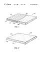
- FIG. 1provides a perspective view of a non-woven fiber batt layer.
- FIG. 2provides a perspective view of a foam layer.
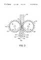
- FIG. 3provides a schematic drawing of a process of the present invention.
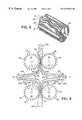
- FIG. 4provides a schematic drawing of an alternative embodiment of a process of the present invention.
- FIG. 5provides a perspective view of a drum having alternative embodiments of convoluted surfaces thereon.
- FIG. 6provides a perspective sectional view of a multi-layer pad of a non-woven fiber batt and a foam having conforming convoluted surfaces.
- FIG. 7provides a perspective sectional view of an alternative embodiment of a multi-layer pad of non-woven fiber batt and a foam having conforming convoluted surfaces.
- FIG. 8provides a perspective sectional view of another alternative embodiment of a multi-layer pad of a non-woven fiber batt and a foam having conforming convoluted surfaces.
- a non-woven batt 100has a longitudinal dimension 102 , a lateral dimension 104 and a transverse dimension 106 .
- the non-woven batt 100may include a blend of different types of fibers 108 having varying diameters and deniers, and fibers which are hollow, solid and crimped. Blending different types of fibers 108 creates dead air spaces which contribute to the resiliency of the convoluted multi-layer pad 500 of the present invention (See FIGS. 3, 4 and 5 ) and lends to the integrity of the non-woven batt 100 .
- the fibers 108 of the non-woven batt 100can be synthetic fibers which are known in the art, for example polyester and polypropylene.
- the fibers 108are substantially synthetic fibers having a melting point in the range of about 189°-206° C. (300°-330° F.).
- the fibers 108are polyester fibers having a melting point substantially in the above specified range.
- other synthetic fibers known in the artalso may be used, such as polypropylene, having melt ranges close to or below the above-specified range.
- natural fiberssuch as camel, llama, wool, cashmere, or cotton can be incorporated with synthetic fibers to form the non-woven batt 100 . Because natural fibers may tend to generate smoke when in contact with a heated cutter, the percentage of natural fiber incorporated into the non-woven batt 100 should be within a range which will not create an environmental or health hazard during a heated cutting operation.
- the fibers 108 of the non-woven batt 100can also be densified.
- Densified fibers as used hereinrefers to fibers having a weight to thickness ratio of at least 57 grams (2 ounces) per 3.8 centimeter (1.5 inch) thickness for a 30.5 square centimeter (1 square foot) area of batt.
- the fibers 108can be oriented substantially horizontally 108 a along the longitudinal dimension 102 and traverse dimension 106 of the non-woven batt 100 .
- the non-woven batt 100can be comprised of horizontally oriented fibers 108 a , and vertically oriented fibers 108 b along the lateral dimension 104 of the non-woven batt 100 .
- the non-woven batt 100is formed from substantially vertically oriented fibers 108 b , as vertically oriented fibers 108 b have better convolution retention properties as compared to horizontally oriented fibers 108 a , as discussed below.
- the batt 100can be formed using one of the several processes for converting a source of fiber into a non-woven batt 100 , as is known in the art.
- the fibers 108may receive an application of a resin to improve the structural integrity of the non-woven batt 100 , or alternatively may incorporate a portion of low melting fibers which will melt to bond high melt fibers in the non-woven batt 100 on application of heat.
- the ends of the fibers 108 in non-woven batt 100may be brushed to improve the entwining of individual fibers of one end into adjacent ends. Adjacent ends of fibers 108 may be of substantially the same height, or alternatively may have different heights in a repeating pattern.
- the structure and manufacture of a batt incorporating vertically oriented fibersis described in more detail in U.S. Pat. No. 5,702,801, the entire disclosure of which is incorporated herein by reference.
- the non-woven batt 100may have an initial thickness of up to about eighteen (18) inches.
- the fibers 108are spray bonded together with an adhesive and then compressed by rolling the fibers 108 to form the non-woven batt 100 , as is known in the art.
- the fibers 108are oven-baked together and then rolled and cooled to form the non-woven batt 100 .
- a foam layer 200has a longitudinal dimension 202 , a lateral dimension 204 and a transverse dimension 206 .
- the foam layer 200preferably is a cellular foam structure which is resilient along its dimensions 202 , 204 , 206 .
- the foam layer 200compresses when weight or a load is placed along its dimensions 202 , 204 , 206 and returns generally to its original state when the weight or load is removed.
- the structure of a foam layer having a convoluted surfaceis described in U.S. Pat. No. 5,317,768, the entire disclosure of which is incorporated herein by reference.
- the lateral dimension 204 of the foam layer 200can be as large or as small as desired. In an alternative embodiment, the lateral dimension 204 is in the range of one half to three (1 ⁇ 23) inches. In another alternative embodiment, the lateral dimension 204 is in the range of one to one and one half (1-11 ⁇ 2) inches. In the preferred embodiment, the lateral dimension 204 of the foam layer 200 is approximately 11 ⁇ 4 inches.
- the process of forming non-woven batt 100 having convoluted surface 160is generally accomplished by transporting the non-woven batt 100 along its longitudinal dimension 102 while compressing the non-woven batt 100 along its lateral dimension 104 . Concomitantly with compression, the non-woven batt 100 is cut transversly along its lateral dimension 104 to separate the non-woven batt 100 into an upper segment 120 and a lower segment 140 and to provide conforming convoluted surface 160 of the batt upper and lower segments 120 , 140 .
- the batt upper and lower segments 120 , 140each have an upper surface 122 , 142 and a lower surface 132 , 152 , respectively.
- the convoluted surface 160 of the batt upper segment 120is proximate to its lower surface 132 .
- the convoluted surface 160 of the batt lower segment 140is proximate to its upper surface 142 .
- a process for forming a non-woven fiber pad having a convoluted surfaceis disclosed, for example, in the aforementioned in U.S. patent application Ser. No. 09/363,726, entitled Convoluted Surface Fiber Pad, having as co-inventor Steven Eugene Ogle (the same inventor here) and filed on or about Jul. 29, 1999, the entire disclosure of which is incorporated herein by reference.
- the process of forming foam layer 200 having a convoluted surface 260is generally accomplished by transporting the foam layer 200 along its longitudinal dimension 202 while compressing the foam layer 200 along its lateral dimension 204 . Concomitantly with compression, the foam layer 200 is cut transversly along its lateral dimension 204 to separate the foam layer 200 into an upper segment 220 and a lower segment 240 and to provide conforming convoluted surface 260 of the foam layer upper and lower segments 220 , 240 , respectively.
- the foam layer upper and lower segments 220 , 240each have an upper surface 222 , 242 and a lower surface 232 , 252 , respectively.
- the convoluted surface 260 of the foam layer upper segment 220is proximate to its lower surface 232 .
- the convoluted surface 260 of the foam layer lower segment 240is proximate to its upper surface 242 .
- the preferred embodiment for transporting the non-woven batt 100 along its longitudinal dimension 102is accomplished by a convey or belt (not shown), although it is to be understood that alternate embodiments are known in the art.
- Compression of the non-woven batt 100 along its lateral dimension 104is preferably accomplished by a pair of drums 10 , 12 having opposite rotational directions D, D′. As the conveyor belt introduces the non-woven batt 100 between the drums 10 , 12 , the drums 10 , 12 draw the non-woven batt 100 to compression.
- D rums 10 , 12each have a convoluted surface 20 with at least one raised pattern thereon.
- the raised patternis generally a plurality of upstanding projections and depressions.
- Alternative embodiments of the raised patterninclude a plurality of pegs 22 , straight edges 24 or waved edges 26 , although it is to be understood that alternative raised patterns are known in the art.
- the convoluted surface 20 of drum 10should not intermesh or come in contact with the convoluted surface 20 of opposite drum 12 as the drums 10 , 12 rotate.
- only one of the drums 10 , 12has a convoluted surface 20 while the other of the drums 10 , 12 does not have a convoluted surface 20 which operates to facilitate the drawing of the batt 100 through the drums 10 , 12 .
- a cutting device 30is positioned generally parallel to and between drum 10 and drum 12 , and along the lateral dimension 104 of non-woven batt 100 as the non-woven batt 100 is transported between the drums 10 , 12 .
- the cutting device 30is positioned proximate the location along the longitudinal dimension 102 of the non-woven batt 100 generally where the convoluted surface 20 of drum 10 or drum , 12 compresses the non-woven batt 100 .
- the cutting device 30cuts through the non-woven batt 100 transversely and along the lateral dimension 104 to separate non-woven batt 100 into an upper segment 120 and a lower segment 140 , each segment 120 , 140 having an upper surface 122 , 142 and a lower surface 132 , 152 , respectively.
- the cutting device 30cuts through the non-woven batt 100 at a point along its lateral dimension 104 either nearer to the upper surface 122 of the batt upper segment 120 or to the lower surface 152 of the batt lower segment 140 , whichever surface 122 or 152 is in contact with the convoluted surface 20 , thus creating convoluted surface 160 of non-woven batt 100 .
- the preferred embodiment for convoluting the foam layer 200is similar to the process for convoluting the non-woven batt 100 .
- Transportation of the foam layer 200 along its longitudinal dimension 202is accomplished with a conveyor belt (not shown), although it is to be understood that alternate embodiments are known in the art.
- Compression of the foam layer 202 along its lateral dimension 204is preferably accomplished by a pair of drums 50 , 52 having opposite rotational directions E, E′.
- the conveyor beltintroduces the foam layer 200 between drums 50 , 52
- the drums 50 , 52draw the foam layer 200 to compression.
- Drums 50 , 52each have a convoluted surface 20 with at least one raised pattern thereon which corresponds to the raised pattern of drums 10 , 12 .
- the convoluted surface 20 of drum 50should not intermesh or come in contact with the convoluted surface 20 of opposite drum 52 as the drums 50 , 52 rotate.
- only one of the drums 50 , 52has a convoluted surface 20 while the other of the drums 50 , 52 does not have a convoluted surface 20 which operates to facilitate the drawing of the foam layer 200 through the drums 50 , 52 .
- a cutting device 70is positioned generally parallel to and between drum 50 and drum 52 , and along the lateral dimension 204 of foam layer 200 as the foam layer 200 is transported between the drums 50 , 52 .
- the cutting device 70is positioned proximate the location along the longitudinal dimension 202 of foam layer 200 where the convoluted surface 20 of drums 50 , 52 compresses the foam layer 200 .
- the cutting device 70cuts through the foam layer 200 transversely and along the lateral dimension 204 to separate foam layer 200 into an upper segment 220 and a lower segment 240 , each segment 220 , 240 having an upper surface 222 , 242 and a lower surface 232 , 252 , respectively.
- the cutting device 70cuts through the foam layer 200 at a point along its lateral dimension 204 either nearer to the upper surface 222 of the foam layer upper segment 220 or to the lower surface 252 of the foam layer lower segment 240 , whichever upper 222 or 252 is in contact with the convoluted surface 20 .
- drums 10 , 12may be positioned closer to or further away from each other depending on lateral dimension 104 of the non-woven batt 100 to be convoluted.
- the distance between drums 50 , 52may be positioned depending on the lateral dimension 204 of the foam layer 200 to be convoluted.
- the convoluted surface 20 of drum 10does not come into contact with or intermesh with the convoluted surface 20 of drum 12 to prevent the cutting device 30 from cutting through the upper surface 122 of the batt upper segment 120 or the lower surface 152 of the batt lower segment 140 .
- the convoluted surface 20 of drum 50does not come into contact with or intermesh with the convoluted surface 20 of drum 52 to prevent the cutting device 70 from cutting through the upper surface 222 of the foam upper segment 220 or the lower surface 252 of the foam lower segment 240 .
- the cutting devices 30 , 70can be heated cutters.
- cutting devices 30 , 70are hot wires.
- the heate cutters of cutting devices 30 and 70can be heated above the melting point of the fibers 108 of the non-woven batt 100 and of the foam 200 , respectively, in order to speed the cutting process.
- the cutting device 30should be heated in the range of about 189 °- 206 ° C. (300°-330° F.).
- non-woven batt 100formed from synthetic fibers 108 having a low melting point
- the heated cutter 30cuts through the non-woven batt 100
- the lower surface 132 of the batt upper segment 120 and the upper surface 142 of the batt lower segment 140are bonded as fibers 108 lose their original plastic memory and then reform as a skin during cooling.
- convoluted surfaces 160 , 260 of the non-woven batt 100 and foam layer 200are generally comprised of projections 302 and depressions 402 having different patterns and configurations depending upon the convoluted surface 20 of the drums 10 , 12 , 50 , 52 .
- a plurality of pegs 22 of drum convoluted surface 20forms a plurality of peaks 304 and basins 404 on convoluted surfaces 160 , 260 of non-woven batt 100 and foam layer 200 .
- a plurality of straight edges 24 on the drum convoluted surface 20forms ridges 306 and valleys 406 on convoluted surfaces 160 , 260 of the non-woven fiber batt 100 and the foam layer 200 .
- Waved ridges 308 and waved valleys 408 on convoluted surfaces 160 , 260 of the fiber batt 100 and foam layer 200are formed of waved ridges on the convoluted surface 20 of the drum.
- the process for forming a convoluted combination fiber and foam padincludes disposing the convoluted surface 160 of at least one of the batt upper and lower segments 120 , 140 in a conforming relationship to the convoluted surface 260 of at least one of the foam layer upper and lower segments 220 , 240 to form a multi-layer pad of a non-woven fiber batt and foam layer having conforming convoluted surfaces.
- the cohesive nature of the non-woven batt 100 and the foam layer 200would provide sufficient bonding in some applications.
- the conforming convoluted surfaces 160 , 260 , of the batt 100 and fiber 200respectively, could be bonded using various bonding agents known in the art.
- the preferred embodiment for forming a multi-layer pad of a non-woven batt and foam layer having conforming convoluted surfacesis accomplished by aligning the pair of drums 10 , 12 substantially above the pair of drums 50 , 52 and convoluting the non-woven batt 100 and the foam layer 200 , respectively, as discussed above.
- the raised pattern of convoluted surface 20 of drums 50 , 52corresponds to the raised pattern of convoluted surface 20 of drums 10 , 12 .
- the upper and lower segments 120 , 140 of the non-woven batt 100are transported in relatively opposite and substantially horizontal directions, the lower surface 132 of the batt upper segment 120 facing relatively downward and the upper surface 142 of the batt lower segment 140 facing relatively downward.
- the convoluted surface 160 of the batt upper and lower segments 120 , 140is facing relatively downward.
- a pair of counter rotating rollers 14 , 16 located generally below drums 10 , 12assist in transporting the segments 120 , 140 of the non-woven batt 100 in relatively opposite and substantially horizontal directions.
- a conveyor belt(not shown) proximate the surfaces opposite the convoluted surface 160 farther assists in transporting the segments 120 , 140 of the non-woven batt 100 in opposite and horizontal directions.
- the upper and lower segments 220 , 240 of the foam layer 200are transported in relatively opposite and substantially horizontal directions, the lower surface 232 of the foam layer upper segment 220 facing relatively upward and the upper surface 242 of the foam layer lower segment 140 also facing relatively upward, and the convoluted surface 260 of the foam layer upper and lower segments 220 , 240 facing relatively upward.
- a pair of counter rotating rollers 54 , 56 located generally above drums 50 , 52assist in transporting the segments 220 , 240 of the foam layer 200 in opposite and substantially horizontal directions.
- a conveyor belt(not shown) proximate the surfaces opposite the convoluted surface 260 further assists in transporting the segments 220 , 240 of the foam layer 200 in opposite and horizontal directions.
- the batt upper segment 120 and the foam upper segment 220come together laterally.
- the batt lower segment 140 and the foam lower segment 240laterally come together.
- the distance between conveyor belts (not shown) proximate the non-convoluted surfaces of the non-woven batt 100 and foam layer 200are adjusted to accomplish the lateral movement.
- the batt convoluted surface 160 and the foam layer convoluted surface 260are aligned to provide the upstanding projections 302 of the batt convoluted surface 160 to conform with or project into the depressions 402 of the foam convoluted surface 260 , and the depressions 402 of the batt convoluted surface 160 to conform with or project into the upstanding projections 302 of the foam convoluted surface 260 .
- alignment of the convoluted surfaces 160 , 260is accomplished by controlling the rotational speeds of drums 10 , 12 and of drums 50 , 52 , and adjusting the horizontal placement of the convoluted surfaces 160 , 260 for proper alignment.
- the peaks 304 of the batt and foam convoluted surfaces 160 , 260conform with or project into the corresponding basins 404 of the convoluted surfaces 260 , 160 of the batt and foam, respectively.
- the ridges 306 of the batt convoluted surface 160 and the foam convoluted surface 260conform with or project into the corresponding valleys 406 of the foam convoluted surface 260 and the batt convoluted surface 160 , respectively.
- the waved ridges 308 of the batt and foam convoluted surfaces 160 , 260conform with or project into the corresponding waved valleys 408 of foam and batt convoluted surfaces 260 , 160 , respectively.
- the convoluted surfaces 160 , 260 of the batt 100 and foam layer 200can be bonded together with a bonding agent.
- the bonding agentcan be applied in various manners and stages throughout the process as is known in the art.
- an apparatus 18 , 20sprays a bonding agent on at least one of the convoluted surfaces 160 , 260 proximate rollers 14 , 16 or rollers 54 , 56 .
- the multi-layer pad of a non-woven batt and a foam layer having conforming convoluted surfacesis for use in mattresses and cushions for sofas, loveseats, chairs and other upholstery products.
- the multi-layer pad 500has convoluted surfaces 160 , 260 generally comprised of projections 302 and depressions 402 in different patterns and configurations depending upon the convoluted surface 20 of the drums 10 , 12 , and 50 , 52 .
- the convoluted surfaces 160 , 260remain integral with unconvoluted thin bases 162 , 262 of the non-woven batt 100 and the foam layer 200 , respectively, to retain stiffness for using the multi-layer pad 500 in items such as sofas, cushions and mattresses.
- convoluted surface 160 and base 162are formed from the same non-woven batt 100 and convoluted surface 260 and base 262 are formed from the same foam layer 200 .
- the non-woven batt component 100 of the multi-layer pad 500may be made of either substantially vertically oriented low melt fibers 108 b or substantially horizontally oriented densified low melt fibers 108 b .
- the projections 302 of convoluted surface 160have a greater ability to retain their shape when cut by the heated cutter 30 , as the vertical orientation of fibers 108 b resists sloughing off portions of the projections 302 during the convolution process.
- projections 302 of the convoluted surfaces 160 , 260extend in the range of approximately one half to one (1 ⁇ 2-1) inch in a lateral direction from depressions 402 . In the preferred embodiment, projections 302 extend approximately three fourths (3 ⁇ 4) inch in a lateral direction from depressions 402 . In another alternative embodiment, unconvoluted thin bases 162 , 262 extend laterally in the range of one fourth to three fourths (1 ⁇ 4-3 ⁇ 4) inches. Preferably, unconvoluted thin bases 162 , 262 extend approximately one half (1 ⁇ 2) inch in the laterally.
Landscapes
- Engineering & Computer Science (AREA)
- Mechanical Engineering (AREA)
- Textile Engineering (AREA)
- Life Sciences & Earth Sciences (AREA)
- Forests & Forestry (AREA)
- Nonwoven Fabrics (AREA)
- Mattresses And Other Support Structures For Chairs And Beds (AREA)
- Laminated Bodies (AREA)
Abstract
Description
Claims (12)
Priority Applications (7)
| Application Number | Priority Date | Filing Date | Title |
|---|---|---|---|
| US09/406,366US6372076B1 (en) | 1999-09-28 | 1999-09-28 | Convoluted multi-layer pad and process |
| PCT/US2000/026675WO2001023175A1 (en) | 1999-09-28 | 2000-09-28 | Convoluted multi-layer pad and process |
| AU79876/00AAU7987600A (en) | 1999-09-28 | 2000-09-28 | Convoluted multi-layer pad and process |
| US10/068,111US6596387B2 (en) | 1999-09-28 | 2002-02-06 | Convoluted multi-layer pad and process |
| US10/445,706US7008691B2 (en) | 1999-09-28 | 2003-05-27 | Convoluted multi-layer pad and process |
| US11/315,948US7452589B2 (en) | 1999-09-28 | 2005-12-22 | Convoluted fiber pad |
| US12/272,601US20090068397A1 (en) | 1999-09-28 | 2008-11-17 | Convoluted fiber pad |
Applications Claiming Priority (1)
| Application Number | Priority Date | Filing Date | Title |
|---|---|---|---|
| US09/406,366US6372076B1 (en) | 1999-09-28 | 1999-09-28 | Convoluted multi-layer pad and process |
Related Child Applications (1)
| Application Number | Title | Priority Date | Filing Date |
|---|---|---|---|
| US10/068,111DivisionUS6596387B2 (en) | 1999-09-28 | 2002-02-06 | Convoluted multi-layer pad and process |
Publications (1)
| Publication Number | Publication Date |
|---|---|
| US6372076B1true US6372076B1 (en) | 2002-04-16 |
Family
ID=23607675
Family Applications (5)
| Application Number | Title | Priority Date | Filing Date |
|---|---|---|---|
| US09/406,366Expired - Fee RelatedUS6372076B1 (en) | 1999-09-28 | 1999-09-28 | Convoluted multi-layer pad and process |
| US10/068,111Expired - Fee RelatedUS6596387B2 (en) | 1999-09-28 | 2002-02-06 | Convoluted multi-layer pad and process |
| US10/445,706Expired - Fee RelatedUS7008691B2 (en) | 1999-09-28 | 2003-05-27 | Convoluted multi-layer pad and process |
| US11/315,948Expired - Fee RelatedUS7452589B2 (en) | 1999-09-28 | 2005-12-22 | Convoluted fiber pad |
| US12/272,601AbandonedUS20090068397A1 (en) | 1999-09-28 | 2008-11-17 | Convoluted fiber pad |
Family Applications After (4)
| Application Number | Title | Priority Date | Filing Date |
|---|---|---|---|
| US10/068,111Expired - Fee RelatedUS6596387B2 (en) | 1999-09-28 | 2002-02-06 | Convoluted multi-layer pad and process |
| US10/445,706Expired - Fee RelatedUS7008691B2 (en) | 1999-09-28 | 2003-05-27 | Convoluted multi-layer pad and process |
| US11/315,948Expired - Fee RelatedUS7452589B2 (en) | 1999-09-28 | 2005-12-22 | Convoluted fiber pad |
| US12/272,601AbandonedUS20090068397A1 (en) | 1999-09-28 | 2008-11-17 | Convoluted fiber pad |
Country Status (3)
| Country | Link |
|---|---|
| US (5) | US6372076B1 (en) |
| AU (1) | AU7987600A (en) |
| WO (1) | WO2001023175A1 (en) |
Cited By (13)
| Publication number | Priority date | Publication date | Assignee | Title |
|---|---|---|---|---|
| US20030235684A1 (en)* | 1999-09-28 | 2003-12-25 | Ogle Steven Eugene | Convoluted multi-layer pad and process |
| US20050173826A1 (en)* | 2003-10-14 | 2005-08-11 | Defranks Michael S. | Method for manufacturing a foam core having channel cuts |
| US20060189238A1 (en)* | 2004-11-05 | 2006-08-24 | Warren Roger D | Molded composite fabrics and methods of making |
| US20080283476A1 (en)* | 2007-05-14 | 2008-11-20 | Global Finishing L.L.C. | Fluid filter and filtering method |
| KR20170138392A (en)* | 2015-02-03 | 2017-12-15 | 로메리카 엔브이 | Cylindrical foam, its use and manufacturing method |
| US20190150631A1 (en)* | 2017-11-17 | 2019-05-23 | Purple Innovation, Llc | Cushions including one or more zones of different materials and related methods of manufacture for improved yield |
| US10589488B2 (en)* | 2014-05-06 | 2020-03-17 | Proprietect L.P. | Foam article |
| US11013340B2 (en)* | 2018-05-23 | 2021-05-25 | L&P Property Management Company | Pocketed spring assembly having dimensionally stabilizing substrate |
| US20210204717A1 (en)* | 2013-09-25 | 2021-07-08 | Cascade Designs, Inc. | Channelized inflatable bodies and methods for making the same |
| US11122910B2 (en) | 2012-10-22 | 2021-09-21 | Dreamwell, Ltd. | Multi-layered convoluted foam layer |
| US20230270262A1 (en)* | 2018-05-23 | 2023-08-31 | L&P Property Management Company | Method Of Disassembling Pocketed Spring Assembly With Dimensionally Stabilizing Substrate |
| US20230309708A1 (en)* | 2022-03-31 | 2023-10-05 | Dreamwell, Ltd. | Hybrid mattress core assemblies |
| US12029325B2 (en) | 2013-09-25 | 2024-07-09 | Cascade Designs, Inc. | Channelized inflatable bodies and methods for making the same |
Families Citing this family (23)
| Publication number | Priority date | Publication date | Assignee | Title |
|---|---|---|---|---|
| US8165950B2 (en)* | 2003-07-10 | 2012-04-24 | Omx Technology Ab | Method and a system for trading stripped bonds |
| GB0320628D0 (en)* | 2003-09-03 | 2003-10-01 | Mss Europ Ltd | A pressure relieving mattress |
| US20050069694A1 (en)* | 2003-09-26 | 2005-03-31 | Gilder Stephen D. | Anti-microbial carpet underlay and method of making |
| US7799967B2 (en)* | 2004-04-08 | 2010-09-21 | Kimberly-Clark Worldwide, Inc. | Differentially expanding absorbent structure |
| US7540307B1 (en) | 2004-10-06 | 2009-06-02 | Indratech Llc | Machine having variable fiber filling system for forming fiber parts |
| US20060075615A1 (en)* | 2004-10-07 | 2006-04-13 | Indratech Llc | Cushion with aesthetic exterior |
| US20070039268A1 (en)* | 2004-12-01 | 2007-02-22 | L&P Property Management Company | Energy Absorptive/Moisture Resistive Underlayment Formed using Recycled Materials and a Hard Flooring System Incorporating the Same |
| US20060144012A1 (en)* | 2004-12-01 | 2006-07-06 | Norman Manning | Recycled energy absorbing underlayment and moisture barrier for hard flooring system |
| US20060260059A1 (en)* | 2005-05-19 | 2006-11-23 | Foamex L.P. | Customizable mattress topper system |
| US7963832B2 (en)* | 2006-02-22 | 2011-06-21 | Cummins Inc. | Engine intake air temperature management system |
| US20070240810A1 (en)* | 2006-04-12 | 2007-10-18 | Indra Tech Llc | Linear process for manufacture of fiber batts |
| US20090061198A1 (en)* | 2007-09-04 | 2009-03-05 | Khambete Surendra S | Polyester padding for gymnasium |
| US20090126137A1 (en)* | 2007-11-16 | 2009-05-21 | Filtration Group, Inc. | Layered Whiteboard Cleaning Tool and Method of Production |
| US8021466B2 (en)* | 2008-03-18 | 2011-09-20 | Carpenter Co. | Fluid flow filter and method of making and using |
| US8365497B2 (en)* | 2008-08-19 | 2013-02-05 | Jordan Byron Rothwell | Insulated panel |
| ES2357597B1 (en)* | 2009-05-29 | 2012-03-27 | Pikolin, S.A. | PROCEDURE FOR THE MANUFACTURE OF PADDED COVERS, COVERS, MATTRESSES AND COATINGS OF REST BASES AND PRODUCT OBTAINED WITH THIS PROCEDURE. |
| WO2011149957A2 (en)* | 2010-05-24 | 2011-12-01 | Banyan Licensing, L.L.C. | Adjustable support apparatus |
| US20130059145A1 (en) | 2010-06-15 | 2013-03-07 | Randall C. Jenkines | Method for making polyurethane foam floor covering products with postconsumer carpet fibers |
| US20140208521A1 (en)* | 2011-07-19 | 2014-07-31 | Kingsdown, Inc. | Foam mattress with progressive support characteristics and method for manufacturing the same |
| US9381671B2 (en)* | 2014-09-30 | 2016-07-05 | Spec Formliners, Inc. | Form liner with backer panel |
| CN107334316B (en)* | 2017-07-07 | 2024-01-19 | 浙江大自然户外用品股份有限公司 | Mattress structure and manufacturing method thereof |
| DE102019131133A1 (en)* | 2018-11-28 | 2020-05-28 | Rogers Corporation | Multi-layer exercise mat |
| FR3105387B1 (en)* | 2019-12-20 | 2021-11-26 | Liebherr Aerospace Toulouse Sas | HEAT EXCHANGER WITH OPTIMIZED FLUID PASSAGES |
Citations (32)
| Publication number | Priority date | Publication date | Assignee | Title |
|---|---|---|---|---|
| US2836228A (en) | 1956-06-15 | 1958-05-27 | Wood Conversion Co | Foam cushion |
| US2841205A (en) | 1955-07-13 | 1958-07-01 | Collins & Aikman Corp | Method of and apparatus for making polyurethane foam coated fabrics |
| US2902091A (en) | 1956-06-15 | 1959-09-01 | Wood Conversion Co | Manufacture of resilient foam with contoured face |
| US3009848A (en) | 1955-03-25 | 1961-11-21 | Ceolon Ges K E Merckle | Elastic foam article and apparatus for making same |
| US3179317A (en) | 1962-05-25 | 1965-04-20 | Allied Chem | Method and apparatus for splitting plastic foam |
| US3186271A (en) | 1961-07-08 | 1965-06-01 | Kaiser Fritz | Process and apparatus for the production of one-piece shaped articles of elastically deformable material |
| US3197357A (en) | 1955-11-21 | 1965-07-27 | Karel H N Schulpen | Yieldably deformable material having open or closed cells and at least one undulatedsurface, or object of this material |
| US3222697A (en) | 1955-07-05 | 1965-12-14 | Mobay Chemical Corp | Profiled polyurethane foam articles of manufacture |
| US3240855A (en) | 1962-11-16 | 1966-03-15 | Allied Chem | Fluffing foam |
| US3258791A (en) | 1964-04-06 | 1966-07-05 | Sidney J Kaplan | Mattress pad |
| US3287196A (en) | 1962-11-23 | 1966-11-22 | Du Pont | Method of styling textiles by contour sculpturing |
| US3394414A (en) | 1966-08-11 | 1968-07-30 | Unger Leo | Foamed body for cushioning material |
| US3616029A (en) | 1968-08-21 | 1971-10-26 | Milbern Co | Method for forming a resilient pad from a plurality of plastic foam sheet members |
| US3738884A (en) | 1966-09-21 | 1973-06-12 | Celanese Corp | Method for producing non-woven fibrous products |
| US3874964A (en) | 1972-05-03 | 1975-04-01 | Grace W R & Co | Laminated fabric and method |
| US3945627A (en) | 1974-10-29 | 1976-03-23 | Serta, Inc. | Box spring assembly using modular coil springs |
| US4064578A (en) | 1975-06-15 | 1977-12-27 | Junji Yamada | Therapeutic cushion |
| US4139919A (en) | 1977-12-07 | 1979-02-20 | Serta, Inc. | Internal support structure for a mattress |
| US4207636A (en) | 1976-09-27 | 1980-06-17 | Tenneco Chemicals, Inc. | Cushion construction |
| US4673452A (en) | 1984-11-30 | 1987-06-16 | Reeves Brothers, Inc. | Method of making foam mattress |
| US4700447A (en)* | 1983-09-09 | 1987-10-20 | Span America Medical Systems, Inc. | Support pad and method of manufacture |
| US5022111A (en) | 1990-06-29 | 1991-06-11 | E. R. Carpenter Company, Inc. | Pressure reduction mattress |
| US5136740A (en) | 1990-05-11 | 1992-08-11 | Eugene Kraft | Varying firmness mattress |
| US5317768A (en) | 1992-09-08 | 1994-06-07 | Serta, Inc. | Spring mattress with a top portion containing foam and fibers |
| US5418989A (en) | 1994-01-13 | 1995-05-30 | Serta, Inc. | Mattress innerspring using formed wire elements |
| US5477573A (en) | 1994-09-30 | 1995-12-26 | Foamex L.P. | Method of manufacturing a zero base convolute pad |
| US5488746A (en) | 1994-10-18 | 1996-02-06 | Hudson; Gary C. | Polyester fiber and foam core mattress pad |
| US5490890A (en) | 1991-11-25 | 1996-02-13 | Actex | Method for making embossed laminated foam articles |
| US5534208A (en) | 1993-09-15 | 1996-07-09 | Foamex L.P. | Three dimensional surface shaping of synthetic foam pads by continuous rotary process |
| US5636397A (en) | 1994-03-01 | 1997-06-10 | Boyd; Terence J. | Futon mattress |
| US5974609A (en) | 1998-06-29 | 1999-11-02 | The Spring Air Company | Quilt top mattress with convoluted foam cushion |
| US5987668A (en) | 1997-09-15 | 1999-11-23 | Span-America Medical Systems, Inc. | Fabric covered mattress pad |
Family Cites Families (24)
| Publication number | Priority date | Publication date | Assignee | Title |
|---|---|---|---|---|
| US1815586A (en)* | 1928-03-05 | 1931-07-21 | Paratex Corp | Process of making rugs |
| US2689811A (en)* | 1950-06-12 | 1954-09-21 | Us Army | Corrugated fibrous battings |
| US3684140A (en)* | 1970-08-03 | 1972-08-15 | Phillips Petroleum Co | Cutter and cutting method |
| CH574807A5 (en)* | 1971-04-02 | 1976-04-30 | Pohl Gerhard | |
| US3786701A (en)* | 1971-11-05 | 1974-01-22 | E Ludwig | Device for cutting urethane foam |
| DE2530499C3 (en)* | 1975-07-09 | 1978-05-24 | Akzo Gmbh, 5600 Wuppertal | Mat sheet and process for its manufacture |
| US4111733A (en)* | 1975-07-23 | 1978-09-05 | S.P.R.L. Limatex | Method and apparatus for continuous manufacture of undulating or corrugated material |
| US4258093A (en)* | 1979-04-26 | 1981-03-24 | Brunswick Corporation | Molding nonwoven, needle punched fabrics into three dimensional shapes |
| SE430231B (en)* | 1980-02-05 | 1983-10-31 | Tetra Pak Int | DEVICE FOR REDUCING THE THICKNESS OF A CURRENT MATERIAL COVER |
| US4441396A (en)* | 1980-09-03 | 1984-04-10 | Societe Mercier Freres | Slitting machine, more particularly for hides and leather, unwoven textile products, rubber products, plastics in plates or rolls |
| US4699032A (en)* | 1984-10-05 | 1987-10-13 | Clark Iii William T | Hot wire cutting system |
| US4668562A (en)* | 1986-04-16 | 1987-05-26 | Cumulus Fibres, Inc. | Vacuum bonded non-woven batt |
| JPS646711A (en) | 1987-06-29 | 1989-01-11 | Shinetsu Polymer Co | Detection of thickness irregularity across width of film or sheet |
| DE3818252A1 (en) | 1988-05-28 | 1989-11-30 | Borgers Johann Gmbh Co Kg | UPHOLSTERY PART FOR SEAT, LOUNGE FURNITURE OD. DGL. |
| US4965901A (en)* | 1989-08-21 | 1990-10-30 | Gaudry Normand | Futon with inflatable core |
| MX9101640A (en)* | 1990-10-26 | 1992-06-05 | Milliken Res Corp | NON-WOVEN FABRIC |
| CA2069125A1 (en)* | 1991-07-01 | 1993-01-02 | Gary J. Jacaruso | Composite forming tool |
| US5702801A (en)* | 1992-02-26 | 1997-12-30 | Shinih Enterprise Co., Ltd. | Method for producing a variable density, corrugated resin-bonded or thermo-bonded fiberfill and the structure produced thereby |
| JP2986689B2 (en)* | 1994-08-29 | 1999-12-06 | ユニ・チャーム株式会社 | Manufacturing method of nonwoven wiper |
| JP3623392B2 (en)* | 1999-03-18 | 2005-02-23 | ユニ・チャーム株式会社 | Nonwoven manufacturing method |
| US6500292B1 (en)* | 1999-07-29 | 2002-12-31 | L&P Property Management Company | Convoluted surface fiber pad |
| US6372076B1 (en) | 1999-09-28 | 2002-04-16 | L&P Property Management Company | Convoluted multi-layer pad and process |
| USD456197S1 (en)* | 2001-03-30 | 2002-04-30 | Carpenter Co. | Mattress pad configuration |
| US6890622B2 (en)* | 2001-12-20 | 2005-05-10 | Kimberly-Clark Worldwide, Inc. | Composite fluid distribution and fluid retention layer having selective material deposition zones for personal care products |
- 1999
- 1999-09-28USUS09/406,366patent/US6372076B1/ennot_activeExpired - Fee Related
- 2000
- 2000-09-28WOPCT/US2000/026675patent/WO2001023175A1/enactiveApplication Filing
- 2000-09-28AUAU79876/00Apatent/AU7987600A/ennot_activeAbandoned
- 2002
- 2002-02-06USUS10/068,111patent/US6596387B2/ennot_activeExpired - Fee Related
- 2003
- 2003-05-27USUS10/445,706patent/US7008691B2/ennot_activeExpired - Fee Related
- 2005
- 2005-12-22USUS11/315,948patent/US7452589B2/ennot_activeExpired - Fee Related
- 2008
- 2008-11-17USUS12/272,601patent/US20090068397A1/ennot_activeAbandoned
Patent Citations (34)
| Publication number | Priority date | Publication date | Assignee | Title |
|---|---|---|---|---|
| US3009848A (en) | 1955-03-25 | 1961-11-21 | Ceolon Ges K E Merckle | Elastic foam article and apparatus for making same |
| US3222697A (en) | 1955-07-05 | 1965-12-14 | Mobay Chemical Corp | Profiled polyurethane foam articles of manufacture |
| US2841205A (en) | 1955-07-13 | 1958-07-01 | Collins & Aikman Corp | Method of and apparatus for making polyurethane foam coated fabrics |
| US3197357A (en) | 1955-11-21 | 1965-07-27 | Karel H N Schulpen | Yieldably deformable material having open or closed cells and at least one undulatedsurface, or object of this material |
| US2836228A (en) | 1956-06-15 | 1958-05-27 | Wood Conversion Co | Foam cushion |
| US2902091A (en) | 1956-06-15 | 1959-09-01 | Wood Conversion Co | Manufacture of resilient foam with contoured face |
| US3186271A (en) | 1961-07-08 | 1965-06-01 | Kaiser Fritz | Process and apparatus for the production of one-piece shaped articles of elastically deformable material |
| US3179317A (en) | 1962-05-25 | 1965-04-20 | Allied Chem | Method and apparatus for splitting plastic foam |
| US3240855A (en) | 1962-11-16 | 1966-03-15 | Allied Chem | Fluffing foam |
| US3287196A (en) | 1962-11-23 | 1966-11-22 | Du Pont | Method of styling textiles by contour sculpturing |
| US3258791A (en) | 1964-04-06 | 1966-07-05 | Sidney J Kaplan | Mattress pad |
| US3394414A (en) | 1966-08-11 | 1968-07-30 | Unger Leo | Foamed body for cushioning material |
| US3738884A (en) | 1966-09-21 | 1973-06-12 | Celanese Corp | Method for producing non-woven fibrous products |
| US3616029A (en) | 1968-08-21 | 1971-10-26 | Milbern Co | Method for forming a resilient pad from a plurality of plastic foam sheet members |
| US3874964A (en) | 1972-05-03 | 1975-04-01 | Grace W R & Co | Laminated fabric and method |
| US3945627A (en) | 1974-10-29 | 1976-03-23 | Serta, Inc. | Box spring assembly using modular coil springs |
| US4064578A (en) | 1975-06-15 | 1977-12-27 | Junji Yamada | Therapeutic cushion |
| US4207636A (en) | 1976-09-27 | 1980-06-17 | Tenneco Chemicals, Inc. | Cushion construction |
| US4139919A (en) | 1977-12-07 | 1979-02-20 | Serta, Inc. | Internal support structure for a mattress |
| US4700447A (en)* | 1983-09-09 | 1987-10-20 | Span America Medical Systems, Inc. | Support pad and method of manufacture |
| US4673452A (en) | 1984-11-30 | 1987-06-16 | Reeves Brothers, Inc. | Method of making foam mattress |
| US5136740A (en) | 1990-05-11 | 1992-08-11 | Eugene Kraft | Varying firmness mattress |
| US5022111A (en) | 1990-06-29 | 1991-06-11 | E. R. Carpenter Company, Inc. | Pressure reduction mattress |
| US5490890A (en) | 1991-11-25 | 1996-02-13 | Actex | Method for making embossed laminated foam articles |
| US5317768A (en) | 1992-09-08 | 1994-06-07 | Serta, Inc. | Spring mattress with a top portion containing foam and fibers |
| US5317768B1 (en) | 1992-09-08 | 1999-09-07 | Serta Inc | Spring mattress with a top portion containing foam and fibers |
| US5688538A (en) | 1993-09-15 | 1997-11-18 | Foamex L.P. | Apparatus for three dimensional surface shaping of synthetic foam |
| US5534208A (en) | 1993-09-15 | 1996-07-09 | Foamex L.P. | Three dimensional surface shaping of synthetic foam pads by continuous rotary process |
| US5418989A (en) | 1994-01-13 | 1995-05-30 | Serta, Inc. | Mattress innerspring using formed wire elements |
| US5636397A (en) | 1994-03-01 | 1997-06-10 | Boyd; Terence J. | Futon mattress |
| US5477573A (en) | 1994-09-30 | 1995-12-26 | Foamex L.P. | Method of manufacturing a zero base convolute pad |
| US5488746A (en) | 1994-10-18 | 1996-02-06 | Hudson; Gary C. | Polyester fiber and foam core mattress pad |
| US5987668A (en) | 1997-09-15 | 1999-11-23 | Span-America Medical Systems, Inc. | Fabric covered mattress pad |
| US5974609A (en) | 1998-06-29 | 1999-11-02 | The Spring Air Company | Quilt top mattress with convoluted foam cushion |
Cited By (28)
| Publication number | Priority date | Publication date | Assignee | Title |
|---|---|---|---|---|
| US20030235684A1 (en)* | 1999-09-28 | 2003-12-25 | Ogle Steven Eugene | Convoluted multi-layer pad and process |
| US7008691B2 (en) | 1999-09-28 | 2006-03-07 | L&P Property Management Company | Convoluted multi-layer pad and process |
| US20060099869A1 (en)* | 1999-09-28 | 2006-05-11 | Mossbeck Niels S | Convoluted fiber pad |
| US7452589B2 (en) | 1999-09-28 | 2008-11-18 | L&P Property Management Company | Convoluted fiber pad |
| US20050173826A1 (en)* | 2003-10-14 | 2005-08-11 | Defranks Michael S. | Method for manufacturing a foam core having channel cuts |
| US7174613B2 (en)* | 2003-10-14 | 2007-02-13 | Dreamwell Ltd | Method for manufacturing a foam core having channel cuts |
| US20060189238A1 (en)* | 2004-11-05 | 2006-08-24 | Warren Roger D | Molded composite fabrics and methods of making |
| US7771517B2 (en) | 2007-05-14 | 2010-08-10 | Global Finishing Solutions, L.L.C. | Filtering method |
| US20080283476A1 (en)* | 2007-05-14 | 2008-11-20 | Global Finishing L.L.C. | Fluid filter and filtering method |
| US11122910B2 (en) | 2012-10-22 | 2021-09-21 | Dreamwell, Ltd. | Multi-layered convoluted foam layer |
| US20210204717A1 (en)* | 2013-09-25 | 2021-07-08 | Cascade Designs, Inc. | Channelized inflatable bodies and methods for making the same |
| US12029325B2 (en) | 2013-09-25 | 2024-07-09 | Cascade Designs, Inc. | Channelized inflatable bodies and methods for making the same |
| US11786052B2 (en)* | 2013-09-25 | 2023-10-17 | Cascade Designs, Inc. | Channelized inflatable bodies and methods for making the same |
| US10589488B2 (en)* | 2014-05-06 | 2020-03-17 | Proprietect L.P. | Foam article |
| KR20170138392A (en)* | 2015-02-03 | 2017-12-15 | 로메리카 엔브이 | Cylindrical foam, its use and manufacturing method |
| US20180000257A1 (en)* | 2015-02-03 | 2018-01-04 | Romerika Nv | Cylindrical foam body, use thereof and method for producing this |
| US10932587B2 (en)* | 2015-02-03 | 2021-03-02 | Romerika Nv | Cylindrical foam body, use thereof and method for producing this |
| US20190150631A1 (en)* | 2017-11-17 | 2019-05-23 | Purple Innovation, Llc | Cushions including one or more zones of different materials and related methods of manufacture for improved yield |
| US11013340B2 (en)* | 2018-05-23 | 2021-05-25 | L&P Property Management Company | Pocketed spring assembly having dimensionally stabilizing substrate |
| US20230270262A1 (en)* | 2018-05-23 | 2023-08-31 | L&P Property Management Company | Method Of Disassembling Pocketed Spring Assembly With Dimensionally Stabilizing Substrate |
| US11771235B2 (en)* | 2018-05-23 | 2023-10-03 | L&P Property Management Company | Pocketed spring assembly having dimensionally stabilizing substrate |
| US20210244193A1 (en)* | 2018-05-23 | 2021-08-12 | L&P Property Management Company | Method Of Making Pocketed Spring Assembly With Substrate |
| US11812860B2 (en)* | 2018-05-23 | 2023-11-14 | L&P Property Management Company | Method of making pocketed spring assembly with substrate |
| US20230389711A1 (en)* | 2018-05-23 | 2023-12-07 | L&P Property Management Company | Pocketed Spring Assembly Having Dimensionally Stabilizing Substrate |
| US20210235882A1 (en)* | 2018-05-23 | 2021-08-05 | L&P Property Management Company | Pocketed Spring Assembly Having Dimensionally Stabilizing Substrate |
| US12137813B2 (en)* | 2018-05-23 | 2024-11-12 | L&P Property Management Company | Pocketed spring assembly having dimensionally stabilizing substrate |
| US12369722B2 (en)* | 2018-05-23 | 2025-07-29 | L&P Property Management Company | Method of disassembling pocketed spring assembly with dimensionally stabilizing substrate |
| US20230309708A1 (en)* | 2022-03-31 | 2023-10-05 | Dreamwell, Ltd. | Hybrid mattress core assemblies |
Also Published As
| Publication number | Publication date |
|---|---|
| AU7987600A (en) | 2001-04-30 |
| US7452589B2 (en) | 2008-11-18 |
| US20090068397A1 (en) | 2009-03-12 |
| US7008691B2 (en) | 2006-03-07 |
| US20060099869A1 (en) | 2006-05-11 |
| US20030235684A1 (en) | 2003-12-25 |
| US6596387B2 (en) | 2003-07-22 |
| WO2001023175A1 (en) | 2001-04-05 |
| US20020069957A1 (en) | 2002-06-13 |
Similar Documents
| Publication | Publication Date | Title |
|---|---|---|
| US6372076B1 (en) | Convoluted multi-layer pad and process | |
| US6500292B1 (en) | Convoluted surface fiber pad | |
| US4207636A (en) | Cushion construction | |
| JP6544777B2 (en) | Cushioning material and cushion | |
| WO2012038737A1 (en) | A padding layer | |
| US7238633B1 (en) | Multi density fiber seat back | |
| JPH0797772A (en) | Cushioning material made of fiber and having ruggedness on the surface and its production | |
| US12274368B2 (en) | Upholstered comfort member | |
| WO1997037070A1 (en) | Three-dimensional structure of carbon fiber and method of manufacturing same | |
| JP3239733U (en) | Hardened high resilience overlay mattresses, hardened high resilience mattresses, hardened high resilience cushions and hardened high resilience pillows | |
| JP2912477B2 (en) | mattress | |
| JP7429453B2 (en) | Buffer material and cushion body for coil springs | |
| JP2003236965A (en) | Cushion material, manufacturing method therefor, and manufacturing equipment used therefor | |
| JP2003010573A (en) | Cushion material and method for manufacturing the same | |
| RU2822586C1 (en) | Furniture element including lignocellulose fibres | |
| JP2002030556A (en) | Fiber-molded wadding | |
| JPH054823Y2 (en) | ||
| JP2024044215A (en) | Hardened high-resilience cushion and hardened high-resilience pillow | |
| JPH07265176A (en) | Mattress for changing position of body | |
| JPH0334158Y2 (en) | ||
| WO2024185592A1 (en) | Production method for shaped fiber sheet, shaped fiber sheet, and fiber product | |
| JP2024031509A (en) | Cured high resilience mattress | |
| JPS622830B2 (en) | ||
| JPH0132918Y2 (en) | ||
| JPH0755964Y2 (en) | Cushion that does not require lateral land |
Legal Events
| Date | Code | Title | Description |
|---|---|---|---|
| AS | Assignment | Owner name:L&P PROPERTY MANAGEMENT COMPANY, CALIFORNIA Free format text:ASSIGNMENT OF ASSIGNORS INTEREST;ASSIGNOR:OGLE, STEVEN EUGENE;REEL/FRAME:010482/0867 Effective date:19990927 | |
| CC | Certificate of correction | ||
| FPAY | Fee payment | Year of fee payment:4 | |
| AS | Assignment | Owner name:POLYESTER FIBERS, LLC, A DELAWARE LIMITED LIABILIT Free format text:ASSIGNMENT OF ASSIGNORS INTEREST;ASSIGNOR:L&P PROPERTY MANAGEMENT COMPANY, A DELAWARE CORPORATION;REEL/FRAME:021785/0568 Effective date:20081103 | |
| AS | Assignment | Owner name:WELLS FARGO BANK, NATIONAL ASSOCIATION, GEORGIA Free format text:SECURITY AGREEMENT;ASSIGNOR:POLYESTER FIBERS, LLC;REEL/FRAME:021936/0262 Effective date:20081124 Owner name:WELLS FARGO BANK, NATIONAL ASSOCIATION,GEORGIA Free format text:SECURITY AGREEMENT;ASSIGNOR:POLYESTER FIBERS, LLC;REEL/FRAME:021936/0262 Effective date:20081124 | |
| REMI | Maintenance fee reminder mailed | ||
| LAPS | Lapse for failure to pay maintenance fees | ||
| STCH | Information on status: patent discontinuation | Free format text:PATENT EXPIRED DUE TO NONPAYMENT OF MAINTENANCE FEES UNDER 37 CFR 1.362 | |
| FP | Expired due to failure to pay maintenance fee | Effective date:20100416 | |
| AS | Assignment | Owner name:POLYESTER FIBERS, LLC, FLORIDA Free format text:RELEASE FROM PATENT AND TRADEMARK SECURITY AGREEMENT;ASSIGNOR:WELLS FARGO BANK, NATIONAL ASSOCIATION;REEL/FRAME:027132/0885 Effective date:20111021 |