US6371935B1 - Aortic catheter with flow divider and methods for preventing cerebral embolization - Google Patents
Aortic catheter with flow divider and methods for preventing cerebral embolizationDownload PDFInfo
- Publication number
- US6371935B1 US6371935B1US09/378,676US37867699AUS6371935B1US 6371935 B1US6371935 B1US 6371935B1US 37867699 AUS37867699 AUS 37867699AUS 6371935 B1US6371935 B1US 6371935B1
- Authority
- US
- United States
- Prior art keywords
- flow divider
- fluid flow
- divider
- fluid
- catheter
- Prior art date
- Legal status (The legal status is an assumption and is not a legal conclusion. Google has not performed a legal analysis and makes no representation as to the accuracy of the status listed.)
- Expired - Lifetime
Links
- 238000000034methodMethods0.000titledescription26
- 230000002490cerebral effectEffects0.000titledescription5
- 230000010102embolizationEffects0.000titledescription3
- 239000012530fluidSubstances0.000claimsabstractdescription135
- 230000010412perfusionEffects0.000claimsabstractdescription37
- 210000002376aorta thoracicAnatomy0.000claimsabstractdescription24
- 238000011144upstream manufacturingMethods0.000claimsabstractdescription5
- 230000002093peripheral effectEffects0.000claimsdescription33
- 239000000463materialSubstances0.000claimsdescription27
- 239000008280bloodSubstances0.000claimsdescription20
- 210000004369bloodAnatomy0.000claimsdescription20
- 230000017531blood circulationEffects0.000claimsdescription16
- 230000003073embolic effectEffects0.000claimsdescription14
- 210000001105femoral arteryAnatomy0.000claimsdescription8
- 239000003351stiffenerSubstances0.000claimsdescription3
- 238000004891communicationMethods0.000claimsdescription2
- 238000004873anchoringMethods0.000abstractdescription9
- 230000001747exhibiting effectEffects0.000abstractdescription3
- 210000004789organ systemAnatomy0.000abstractdescription3
- 210000000709aortaAnatomy0.000description34
- 210000001367arteryAnatomy0.000description7
- 239000000853adhesiveSubstances0.000description6
- 230000001070adhesive effectEffects0.000description6
- 229910045601alloyInorganic materials0.000description5
- 239000000956alloySubstances0.000description5
- 229920001971elastomerPolymers0.000description5
- 239000000806elastomerSubstances0.000description5
- 229920000728polyesterPolymers0.000description5
- -1polyethylenePolymers0.000description5
- 238000003466weldingMethods0.000description5
- 239000004952PolyamideSubstances0.000description4
- 239000004698PolyethyleneSubstances0.000description4
- 239000003146anticoagulant agentSubstances0.000description4
- 229940127219anticoagulant drugDrugs0.000description4
- 239000002131composite materialSubstances0.000description4
- 229920001577copolymerPolymers0.000description4
- 239000004816latexSubstances0.000description4
- 229920000126latexPolymers0.000description4
- 229920002647polyamidePolymers0.000description4
- 229920000573polyethylenePolymers0.000description4
- 229920001296polysiloxanePolymers0.000description4
- 229920002635polyurethanePolymers0.000description4
- 239000004814polyurethaneSubstances0.000description4
- 238000001356surgical procedureMethods0.000description4
- 229920002725thermoplastic elastomerPolymers0.000description4
- 230000008901benefitEffects0.000description3
- 230000002612cardiopulmonary effectEffects0.000description3
- 210000000038chestAnatomy0.000description3
- 239000012528membraneSubstances0.000description3
- 229920000915polyvinyl chloridePolymers0.000description3
- 239000004800polyvinyl chlorideSubstances0.000description3
- 229920001499HeparinoidPolymers0.000description2
- 210000004556brainAnatomy0.000description2
- 239000011248coating agentSubstances0.000description2
- 238000000576coating methodMethods0.000description2
- 230000000694effectsEffects0.000description2
- 230000006870functionEffects0.000description2
- 239000002554heparinoidSubstances0.000description2
- 229940025770heparinoidsDrugs0.000description2
- 208000014674injuryDiseases0.000description2
- BASFCYQUMIYNBI-UHFFFAOYSA-NplatinumChemical compound[Pt]BASFCYQUMIYNBI-UHFFFAOYSA-N0.000description2
- 229920000642polymerPolymers0.000description2
- 239000000126substanceSubstances0.000description2
- 230000008733traumaEffects0.000description2
- 238000002604ultrasonographyMethods0.000description2
- 241001631457CannulaSpecies0.000description1
- HTTJABKRGRZYRN-UHFFFAOYSA-NHeparinChemical compoundOC1C(NC(=O)C)C(O)OC(COS(O)(=O)=O)C1OC1C(OS(O)(=O)=O)C(O)C(OC2C(C(OS(O)(=O)=O)C(OC3C(C(O)C(O)C(O3)C(O)=O)OS(O)(=O)=O)C(CO)O2)NS(O)(=O)=O)C(C(O)=O)O1HTTJABKRGRZYRN-UHFFFAOYSA-N0.000description1
- 238000002583angiographyMethods0.000description1
- 238000013459approachMethods0.000description1
- 210000004191axillary arteryAnatomy0.000description1
- 239000003633blood substituteSubstances0.000description1
- 239000000372cardioplegic agentSubstances0.000description1
- 230000001101cardioplegic effectEffects0.000description1
- 238000013130cardiovascular surgeryMethods0.000description1
- 210000000748cardiovascular systemAnatomy0.000description1
- 230000004087circulationEffects0.000description1
- 150000001875compoundsChemical class0.000description1
- 238000010276constructionMethods0.000description1
- 210000004351coronary vesselAnatomy0.000description1
- 238000011161developmentMethods0.000description1
- 239000000975dyeSubstances0.000description1
- 239000000945fillerSubstances0.000description1
- 238000002594fluoroscopyMethods0.000description1
- PCHJSUWPFVWCPO-UHFFFAOYSA-NgoldChemical compound[Au]PCHJSUWPFVWCPO-UHFFFAOYSA-N0.000description1
- 229910052737goldInorganic materials0.000description1
- 239000010931goldSubstances0.000description1
- 230000010247heart contractionEffects0.000description1
- 210000003709heart valveAnatomy0.000description1
- 229920000669heparinPolymers0.000description1
- 229960002897heparinDrugs0.000description1
- 230000002631hypothermal effectEffects0.000description1
- 238000003384imaging methodMethods0.000description1
- 238000001802infusionMethods0.000description1
- 238000003780insertionMethods0.000description1
- 230000037431insertionEffects0.000description1
- 210000003141lower extremityAnatomy0.000description1
- 238000002595magnetic resonance imagingMethods0.000description1
- 239000003550markerSubstances0.000description1
- 230000007246mechanismEffects0.000description1
- 229910052751metalInorganic materials0.000description1
- 239000002184metalSubstances0.000description1
- 238000002156mixingMethods0.000description1
- 239000000203mixtureSubstances0.000description1
- 238000012986modificationMethods0.000description1
- 230000004048modificationEffects0.000description1
- 210000003739neckAnatomy0.000description1
- 230000000926neurological effectEffects0.000description1
- 229910001000nickel titaniumInorganic materials0.000description1
- 239000004745nonwoven fabricSubstances0.000description1
- WTWWXOGTJWMJHI-UHFFFAOYSA-NperflubronChemical compoundFC(F)(F)C(F)(F)C(F)(F)C(F)(F)C(F)(F)C(F)(F)C(F)(F)C(F)(F)BrWTWWXOGTJWMJHI-UHFFFAOYSA-N0.000description1
- 229960001217perflubronDrugs0.000description1
- 229910052697platinumInorganic materials0.000description1
- 239000011148porous materialSubstances0.000description1
- 229940107685reoproDrugs0.000description1
- 238000007789sealingMethods0.000description1
- 238000007493shaping processMethods0.000description1
- 239000007787solidSubstances0.000description1
- 238000000638solvent extractionMethods0.000description1
- 239000010935stainless steelSubstances0.000description1
- 229910001220stainless steelInorganic materials0.000description1
- 210000003270subclavian arteryAnatomy0.000description1
- 229910052715tantalumInorganic materials0.000description1
- GUVRBAGPIYLISA-UHFFFAOYSA-Ntantalum atomChemical compound[Ta]GUVRBAGPIYLISA-UHFFFAOYSA-N0.000description1
- TXEYQDLBPFQVAA-UHFFFAOYSA-NtetrafluoromethaneChemical classFC(F)(F)FTXEYQDLBPFQVAA-UHFFFAOYSA-N0.000description1
- 239000012815thermoplastic materialSubstances0.000description1
- 229920001187thermosetting polymerPolymers0.000description1
- 238000013175transesophageal echocardiographyMethods0.000description1
- WFKWXMTUELFFGS-UHFFFAOYSA-NtungstenChemical compound[W]WFKWXMTUELFFGS-UHFFFAOYSA-N0.000description1
- 229910052721tungstenInorganic materials0.000description1
- 239000010937tungstenSubstances0.000description1
- 210000001364upper extremityAnatomy0.000description1
- 239000002759woven fabricSubstances0.000description1
Images


Classifications
- A—HUMAN NECESSITIES
- A61—MEDICAL OR VETERINARY SCIENCE; HYGIENE
- A61M—DEVICES FOR INTRODUCING MEDIA INTO, OR ONTO, THE BODY; DEVICES FOR TRANSDUCING BODY MEDIA OR FOR TAKING MEDIA FROM THE BODY; DEVICES FOR PRODUCING OR ENDING SLEEP OR STUPOR
- A61M25/00—Catheters; Hollow probes
- A61M25/0067—Catheters; Hollow probes characterised by the distal end, e.g. tips
- A—HUMAN NECESSITIES
- A61—MEDICAL OR VETERINARY SCIENCE; HYGIENE
- A61B—DIAGNOSIS; SURGERY; IDENTIFICATION
- A61B17/00—Surgical instruments, devices or methods
- A61B17/12—Surgical instruments, devices or methods for ligaturing or otherwise compressing tubular parts of the body, e.g. blood vessels or umbilical cord
- A61B17/12022—Occluding by internal devices, e.g. balloons or releasable wires
- A61B17/12027—Type of occlusion
- A61B17/12036—Type of occlusion partial occlusion
- A—HUMAN NECESSITIES
- A61—MEDICAL OR VETERINARY SCIENCE; HYGIENE
- A61B—DIAGNOSIS; SURGERY; IDENTIFICATION
- A61B17/00—Surgical instruments, devices or methods
- A61B17/12—Surgical instruments, devices or methods for ligaturing or otherwise compressing tubular parts of the body, e.g. blood vessels or umbilical cord
- A61B17/12022—Occluding by internal devices, e.g. balloons or releasable wires
- A61B17/12027—Type of occlusion
- A61B17/1204—Type of occlusion temporary occlusion
- A61B17/12045—Type of occlusion temporary occlusion double occlusion, e.g. during anastomosis
- A—HUMAN NECESSITIES
- A61—MEDICAL OR VETERINARY SCIENCE; HYGIENE
- A61B—DIAGNOSIS; SURGERY; IDENTIFICATION
- A61B17/00—Surgical instruments, devices or methods
- A61B17/12—Surgical instruments, devices or methods for ligaturing or otherwise compressing tubular parts of the body, e.g. blood vessels or umbilical cord
- A61B17/12022—Occluding by internal devices, e.g. balloons or releasable wires
- A61B17/12099—Occluding by internal devices, e.g. balloons or releasable wires characterised by the location of the occluder
- A61B17/12109—Occluding by internal devices, e.g. balloons or releasable wires characterised by the location of the occluder in a blood vessel
- A—HUMAN NECESSITIES
- A61—MEDICAL OR VETERINARY SCIENCE; HYGIENE
- A61B—DIAGNOSIS; SURGERY; IDENTIFICATION
- A61B17/00—Surgical instruments, devices or methods
- A61B17/12—Surgical instruments, devices or methods for ligaturing or otherwise compressing tubular parts of the body, e.g. blood vessels or umbilical cord
- A61B17/12022—Occluding by internal devices, e.g. balloons or releasable wires
- A61B17/12131—Occluding by internal devices, e.g. balloons or releasable wires characterised by the type of occluding device
- A61B17/12136—Balloons
- A—HUMAN NECESSITIES
- A61—MEDICAL OR VETERINARY SCIENCE; HYGIENE
- A61M—DEVICES FOR INTRODUCING MEDIA INTO, OR ONTO, THE BODY; DEVICES FOR TRANSDUCING BODY MEDIA OR FOR TAKING MEDIA FROM THE BODY; DEVICES FOR PRODUCING OR ENDING SLEEP OR STUPOR
- A61M25/00—Catheters; Hollow probes
- A61M25/10—Balloon catheters
- A61M25/1002—Balloon catheters characterised by balloon shape
- A—HUMAN NECESSITIES
- A61—MEDICAL OR VETERINARY SCIENCE; HYGIENE
- A61B—DIAGNOSIS; SURGERY; IDENTIFICATION
- A61B17/00—Surgical instruments, devices or methods
- A61B17/12—Surgical instruments, devices or methods for ligaturing or otherwise compressing tubular parts of the body, e.g. blood vessels or umbilical cord
- A61B17/12022—Occluding by internal devices, e.g. balloons or releasable wires
- A61B2017/1205—Introduction devices
- A—HUMAN NECESSITIES
- A61—MEDICAL OR VETERINARY SCIENCE; HYGIENE
- A61M—DEVICES FOR INTRODUCING MEDIA INTO, OR ONTO, THE BODY; DEVICES FOR TRANSDUCING BODY MEDIA OR FOR TAKING MEDIA FROM THE BODY; DEVICES FOR PRODUCING OR ENDING SLEEP OR STUPOR
- A61M25/00—Catheters; Hollow probes
- A61M25/0021—Catheters; Hollow probes characterised by the form of the tubing
- A61M25/0023—Catheters; Hollow probes characterised by the form of the tubing by the form of the lumen, e.g. cross-section, variable diameter
- A61M25/0026—Multi-lumen catheters with stationary elements
- A61M2025/0037—Multi-lumen catheters with stationary elements characterized by lumina being arranged side-by-side
- A—HUMAN NECESSITIES
- A61—MEDICAL OR VETERINARY SCIENCE; HYGIENE
- A61M—DEVICES FOR INTRODUCING MEDIA INTO, OR ONTO, THE BODY; DEVICES FOR TRANSDUCING BODY MEDIA OR FOR TAKING MEDIA FROM THE BODY; DEVICES FOR PRODUCING OR ENDING SLEEP OR STUPOR
- A61M25/00—Catheters; Hollow probes
- A61M25/0067—Catheters; Hollow probes characterised by the distal end, e.g. tips
- A61M25/0068—Static characteristics of the catheter tip, e.g. shape, atraumatic tip, curved tip or tip structure
- A61M2025/0073—Tip designed for influencing the flow or the flow velocity of the fluid, e.g. inserts for twisted or vortex flow
- A—HUMAN NECESSITIES
- A61—MEDICAL OR VETERINARY SCIENCE; HYGIENE
- A61M—DEVICES FOR INTRODUCING MEDIA INTO, OR ONTO, THE BODY; DEVICES FOR TRANSDUCING BODY MEDIA OR FOR TAKING MEDIA FROM THE BODY; DEVICES FOR PRODUCING OR ENDING SLEEP OR STUPOR
- A61M25/00—Catheters; Hollow probes
- A61M25/10—Balloon catheters
- A61M2025/1043—Balloon catheters with special features or adapted for special applications
- A61M2025/1072—Balloon catheters with special features or adapted for special applications having balloons with two or more compartments
- A—HUMAN NECESSITIES
- A61—MEDICAL OR VETERINARY SCIENCE; HYGIENE
- A61M—DEVICES FOR INTRODUCING MEDIA INTO, OR ONTO, THE BODY; DEVICES FOR TRANSDUCING BODY MEDIA OR FOR TAKING MEDIA FROM THE BODY; DEVICES FOR PRODUCING OR ENDING SLEEP OR STUPOR
- A61M25/00—Catheters; Hollow probes
- A61M25/10—Balloon catheters
- A61M2025/1043—Balloon catheters with special features or adapted for special applications
- A61M2025/1095—Balloon catheters with special features or adapted for special applications with perfusion means for enabling blood circulation while the balloon is in an inflated state or in a deflated state, e.g. permanent by-pass within catheter shaft
- A—HUMAN NECESSITIES
- A61—MEDICAL OR VETERINARY SCIENCE; HYGIENE
- A61M—DEVICES FOR INTRODUCING MEDIA INTO, OR ONTO, THE BODY; DEVICES FOR TRANSDUCING BODY MEDIA OR FOR TAKING MEDIA FROM THE BODY; DEVICES FOR PRODUCING OR ENDING SLEEP OR STUPOR
- A61M25/00—Catheters; Hollow probes
- A61M25/0067—Catheters; Hollow probes characterised by the distal end, e.g. tips
- A61M25/0068—Static characteristics of the catheter tip, e.g. shape, atraumatic tip, curved tip or tip structure
- A61M25/007—Side holes, e.g. their profiles or arrangements; Provisions to keep side holes unblocked
Definitions
- This inventionrelates to a catheter stem that reduces the volume of embolic material, which may be knocked loose from an artery all or the wall of a chamber of the heart as a result of a medical procedure, from entering a selected oxygenated blood carrying artery system. More specifically, the invention relates to a catheter for isolating and perfusing a segment of a patient's cardiovascular system and for directing circulatory flow around the isolated segment. More particularly, it relates to an apparatus for deployment within a patient's aortic arch and to methods for selectively perfusing the arch vessels with a fluid, while directing blood flow within the aortic lumen past the isolated arch vessels.
- embolic materialmay be knocked loose from arterial walls, heart valves, or from the interior walls of the chambers of the heart, and pumped to the brain, where the resulting blockages may cause neurological damage.
- Cardiopulmonary bypass pumpsare frequently used to pump blood in the patient while the heart is stopped during surgery, and bypass pumps generally include a filter mechanism to trap embolic material from the blood before the oxygenated blood is returned to the body.
- embolic material from within the heartmay be pumped to the brain.
- Aortic perfusion shuntsas described in common owned and copending U.S. patent application, Ser. No. 09/212,580, filed Dec. 15, 1998, claiming the benefit of provisional application, Ser. No. 60/069,470, filed Dec. 15, 1997, hereby incorporated in its entirety, have been developed that allow the blood from the heart to perfuse the body, while providing separate perfusion of the arch vessels.
- the aortic perfusion shunts describedrepresent a significant step forward in protection against cerebral embolization, however, there remains a tremendous need for further improvements in devices and methods for protecting a patient against the potential of cerebral embolization.
- the inventionis a catheter with a fluid flow control member called a deflector or a fluid flow divider positioned near the distal end of the catheter for dividing a first lumen into two channels near a point where a second lumen branches from the first lumen, and for perfusing the branch lumen.
- a fluid flow control membercalled a deflector or a fluid flow divider positioned near the distal end of the catheter for dividing a first lumen into two channels near a point where a second lumen branches from the first lumen, and for perfusing the branch lumen.
- the flow dividermay be formed in a variety of configurations. In general the flow divider will have an undeployed or collapsed state and an expanded or deployed state. The flow divider may be deployed from an exterior surface of the catheter shaft, or it may be deployed from within a lumen in the catheter shaft. In embodiments wherein the flow divider is coupled to an exterior surface, the flow divider will preferably have an undeployed state wherein the flow divider is contained in a relatively small volume around the circumference of the distal end (nearest the heart) of the catheter, having an exterior circumference that is preferably not significantly larger than the exterior circumference of the catheter.
- the flow dividerpreferably has an undeployed state that is sized and configured for storage within a lumen in the catheter.
- the catheterwill generally have a deployed state in which the length and width of the flow divider is sufficient to divide blood flow in the aorta in the vicinity of the ostia of the arch vessels.
- the flow dividermay comprise one or more inflatable chambers or one or more selectively deployable shrouds.
- the inflatable chambersmay be relatively non-compliant or they may be compliant, exhibiting elastic behavior after initial inflation to closely fit the aortic lumen size and curvature.
- the cathetermay further include one or more additional or auxiliary flow control members located upstream or downstream from the flow divider to further segment the patient's circulatory system for selective perfusion to different organ systems within the body or to assist in anchoring the catheter in a desired position.
- auxiliary flow control membersmay comprise inflatable balloons or selectively deployable external catheter valves.
- the anchoring membersmay be inflatable balloons or other anchoring structures that provide sufficient force or friction to prevent the catheter from drifting from a selected position within the aorta.
- the catheter shaftincludes at least three lumens, one lumen for inflating or otherwise deploying the flow divider, a second for perfusion of the arch vessels, and a third guidewire lumen.
- additional lumensmay be included for deploying the auxiliary flow control members, and for measuring the pressure at desired locations within the aorta.
- the cathetermay be configured for retrograde deployment via a peripheral artery, such as the femoral artery, or it may be configured for antegrade deployment via an aortotomy incision or direct puncture in the ascending aorta.
- Methods according to the present inventionare described using the aortic catheter for occluding and compartmentalizing or partitioning the patient's aortic lumen and for performing selective filtered aortic perfusion.
- FIG. 1shows a bottom view of a first embodiment of the aortic catheter of the invention configured for retrograde deployment via a peripheral artery access point, such as the femoral artery.
- FIG. 2shows a side view of the catheter of FIG. 1, showing the divider in a collapsed state.
- FIG. 3shows a cross section of the aortic catheter of FIG. 1 taken along line 3 — 3 in FIG. 1 .
- FIG. 4shows a top view of the catheter of FIG. 1 with the flow divider deployed.
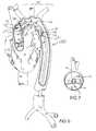
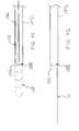
- FIG. 5shows a perspective view of the distal region of the catheter of FIG. 1 deployed within an aortic arch.
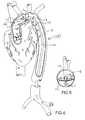
- FIG. 6shows a side view of the catheter of FIG. 5 deployed within an aortic arch.
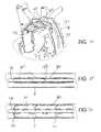
- FIG. 7shows a lateral cross section of the aortic lumen and of the catheter of FIG. 6 taken along line 7 — 7 .
- FIG. 8shows an alternate embodiment of the catheter of FIG. 7, with the flow divider curved in a direction opposite that shown in FIG. 7 .
- FIG. 9shows an embodiment of the catheter of the invention wherein a distal end of the catheter extends through the divider and beyond the end of the divider.
- FIG. 10shows an embodiment of the catheter of the invention wherein the catheter shaft extends below the divider, then above the divider, and then below the divider again, at different points along the catheter.
- FIG. 11shows a side view of the catheter of FIG. 10 deployed within the aortic arch.
- FIG. 12shows a catheter similar to the catheter of FIG. 10, but with the divider periphery concave on its upper surface.
- FIG. 13shows a perspective view of an embodiment of the catheter of the invention including a deployed auxiliary flow control member positioned between the flow divider and the distal end of the catheter.
- FIG. 14shows a perspective view of the catheter of FIG. 13 with the auxiliary flow control member partially collapsed.
- FIG. 15shows an embodiment of the catheter of the invention configured for antegrade deployment.
- FIG. 16shows another embodiment of the catheter of the invention configured for antegrade deployment, showing a divider that is significantly shorter than the divider described in previous embodiments.
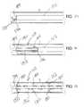
- FIG. 17shows a cut-away view of an embodiment of the flow divider including a mesh or porous portion for perfusing from the upper surface of the flow divider.
- FIG. 18shows a cut-away view of an alternate internal structure of the flow divider of FIG. 17 .
- FIG. 19shows an embodiment of the flow divider of the invention comprising a peripheral tube and membrane structure.
- FIG. 20shows a cross section of the flow divider of FIG. 19 taken along line 20 — 20 .
- FIG. 21shows an embodiment of the flow divider of the invention with welds or joined areas between an upper and a lower film of the flow divider to give additional structure and rigidity to the flow divider.
- FIG. 22shows a cross section of the flow divider of FIG. 20 taken along line 22 — 22 .
- FIG. 23shows an alternate embodiment of FIG. 21 with larger joined areas between the upper and lower films of the flow divider.
- FIG. 24shows an embodiment of the flow divider having a membrane or film portion and a peripheral tube portion, that is deployed using a pair of wires.
- FIG. 25shows a cross section of the flow divider of FIG. 24 taken along line 25 — 25 .
- FIG. 26shows a cross section of an embodiment of the flow divider that is sack-like, rather than having a peripheral channel, and that uses a pair of deployment wires to deploy.
- FIG. 27shows an alternate embodiment of the flow divider of FIG. 24 that is deployed using only a single wire.
- FIG. 28shows a perspective view of an embodiment of the catheter of the invention wherein the flow divider comprises a shroud deployed by means of movable ribs.
- FIG. 29shows a top view of the catheter of FIG. 28 in a collapsed configuration.
- FIG. 30shows a top view of the catheter of FIG. 28 in a deployed configuration.
- FIG. 31shows a first embodiment of the flow divider of the invention deployed from a lumen within a catheter.
- FIG. 32shows a cross section of the flow divider and aorta of FIG. 31 taken transversely through the aorta.
- FIG. 33shows a flow divider, having a flexible stiffening spine, deployed from within a lumen having an opening in the distal end of the catheter and coupled to a deployment wire at a point intermediate the ends of the spine.
- FIG. 34shows the flow divider and catheter of FIG. 33 with the deployment wire retracted to the distal end of the catheter so that the catheter is positioned for perfusion of the arch vessels.
- FIG. 35shows the flow divider of FIG. 33 partially withdrawn into the catheter.
- FIG. 36shows an alternate embodiment of the flow divider of FIG. 33 with an additional withdrawal wire.
- FIG. 37shows the flow divider of FIG. 36 partially withdrawn into the catheter.
- FIG. 38shows a fully deployed flow divider similar in construction to the flow divider of FIG. 28, but that is deployed from within a lumen in a catheter shaft.
- FIG. 39shows the flow divider of FIG. 38 in an undeployed state within the catheter.
- FIG. 40shows the flow divider of FIG. 38 partially deployed.
- FIG. 41shows an embodiment of the flow divider comprising a flexible tongue that is folded back within the catheter shaft, and deployed using a deployment wire to push the flow divider out.
- FIG. 42shows the flow divider of FIG. 41 fully deployed, and with the deployment wire retracted.
- the catheter described herein with all of its preferred featuresrepresents a versatile device having multiple uses.
- the inventionprovides a catheter having a flow divider, indicated generally by the reference number 110 in the accompanying drawings, positioned near the distal end of the catheter for dividing the blood flow through a lumen, preferably at a point where at least one second lumen branches from the first lumen, and for perfusing the branch lumen or lumens.
- a flow dividerindicated generally by the reference number 110 in the accompanying drawings, positioned near the distal end of the catheter for dividing the blood flow through a lumen, preferably at a point where at least one second lumen branches from the first lumen, and for perfusing the branch lumen or lumens.
- the inventionwill be described more specifically herein relating to an aortic catheter having a flow divider 110 configured to be positioned in the aortic arch and having a length sufficient to divide the blood flow in the aortic lumen so that the arch vessels are at least partially isolated.
- the flow divider 110will have an undeployed state wherein the flow divider 110 is contained in a relatively small volume around the circumference of the distal end of the catheter, nearest the heart.
- the catheterwill generally have a deployed state in which the length and width of the flow divider 110 is sufficient to divide blood flow in the aorta in the vicinity of the ostia of the arch vessels, and an undeployed state in which the flow divider 110 is collapsed around the shaft of the catheter and preferably has an exterior circumference that is not significantly larger than the exterior circumference of the catheter.
- the flow divider 110may comprise one or more inflatable chambers or one or more selectively deployable shrouds.
- the balloonsmay be relatively non-compliant or they may be compliant, exhibiting elastic behavior after initial inflation, for example, to closely fit the aortic lumen size and curvature.
- the cathetermay further include one or more additional or auxiliary flow control members located on the catheter either distal or proximal from the flow divider 110 to further segment the patient's circulatory system for selective perfusion to different organ systems within the body or to assist in anchoring the catheter in a desired position.
- auxiliary flow control membersmay comprise inflatable balloons or selectively deployable external catheter valves.
- the anchoring membersmay be inflatable balloons or other anchoring structures that provide sufficient force or friction to prevent the catheter from drifting from a selected position within the aorta.
- auxiliary flow control membersinclude, but are not limited to, expandable or inflatable members such as inflatable balloons and valves including collapsible/expandable valves of various configurations including retrograde valves, antegrade valves, and various central flow and peripheral flow valves.
- expandable or inflatable memberssuch as inflatable balloons and valves including collapsible/expandable valves of various configurations including retrograde valves, antegrade valves, and various central flow and peripheral flow valves.
- a combination of valves and inflatable membersmay be used as appropriate for a given procedure, thus in some embodiments, the catheter body can include one or more antegrade and retrograde valves, as well as one or more inflatable balloons.
- Inflatable balloons and collapsible/deployable valveshave been previously described, and are known in the industry, and any desirable or practical inflatable balloon or deployable valve may be used.
- Inflatable balloonstypically include an interior chamber that is in fluid communication with an inflation lumen extending within the catheter shaft from a location from within
- the flow divider 110and any auxiliary flow control members, or anchoring members, if present, are mounted directly on an elongated catheter shaft.
- the catheter shaftincludes at least three lumens, one lumen for inflating or otherwise deploying the flow divider 110 , a second for perfusion of the arch vessels, and a third guidewire lumen.
- additional lumensmay be included for deploying the auxiliary flow control members, for measuring the pressure at desired locations within the aorta, or for perfusing other isolated segments of the patient's circulatory system.
- the cathetermay be configured for retrograde deployment via a peripheral artery, such as the femoral artery, or it may be configured for antegrade deployment via an aortotomy incision or direct puncture in the ascending aorta.
- the catheteris characterized by a flexible catheter shaft placed by surgical cutdown or needle/introducer guidewire technique into the vessels of the lower or upper extremity or neck. Other large internal vessels may also be used.
- Anticoagulantssuch as heparin and heparinoids
- Anticoagulantsmay be applied to the surfaces of the catheter and/or flow control members as desired. Anticoagulants may be painted or sprayed onto the device. Anticoagulants other than heparinoids may also be used, for example monoclonal antibodies such as REOPRO (Eli Lilly and Co., Indianapolis, Ind.). A chemical dip comprising the anticoagulant may also be used. Other methods known in the art for applying chemicals to catheters may be used.
- FIG. 1illustrates a first embodiment of the aortic catheter 100 of the invention.
- the aortic catheter 100has an elongated catheter shaft 102 having a proximal end 104 , that preferably extends out of the patient's body, and a distal end 106 closest to the patient's heart.
- the elongated catheter shaft 102preferably has an overall length sufficient to reach from the arterial access point where it is inserted into the patient to its deployed position within the aorta.
- the elongated catheter shaft 102preferably has an overall length from approximately 60 cm to 120 cm, and more preferably 70 cm to 90 cm.
- the elongated catheter shaft 102has an outer diameter that is preferably approximately 9 to 22 French (3.0 to 7.3 mm), and more preferably 12 to 18 French (4.0 to 6.0 mm) for use in adult human patients. Catheters for pediatric use, or use in non-human subjects, may require different dimensions and would be scaled accordingly.
- the elongated catheter shaft 102is preferably formed of a flexible thermoplastic material, a thermoplastic elastomer, or a thermoset elastomer.
- Suitable materials for use in the elongated catheter shaft 102include, but are not limited to, polyvinylchloride, polyurethane, polyethylene, polyamides, polyesters, silicone, latex, and alloys or copolymers thereof, as well as braided, coiled or counterwound wire or filament reinforced composites. Additionally or alternatively, the elongated catheter shaft 102 may be constructed using metallic tubing or a solid wire, for example stainless steel hypodermic tubing or wire or superelastic nickel-titanium alloy tubing or wire.
- the aortic catheter 100includes one or more location markers 116 , such as radiopaque markers and/or sonoreflective markers, to enhance imaging of the aortic catheter 100 during deployment using standard fluoroscopy, ultrasound, MRI, MRA, transesophageal echocardiography, or other techniques.
- location markers 116such as radiopaque markers and/or sonoreflective markers, to enhance imaging of the aortic catheter 100 during deployment using standard fluoroscopy, ultrasound, MRI, MRA, transesophageal echocardiography, or other techniques.
- a radiopaque location marker 116is positioned near the distal end 106 of the catheter shaft 102 , and another near the proximal end of the flow divider 110 , to assist in positioning the flow divider 110 within the aortic arch.
- the radiopaque location markers 116may be formed as a ring or disk of dense radiopaque metal such as gold, platinum, tantalum, tungsten, or compounds or alloys thereof, or a ring of a polymer or adhesive material heavily loaded with a radiopaque filler material.
- the flow divider 110is mounted proximate the distal end 106 of the elongated catheter shaft 102 .
- the flow divider 110is shown in the form of a flat elongate expandable inflatable balloon bonded to the catheter shaft 102 by heat welding or with an adhesive.
- the inflatable flow divider 110has a deflated state in which the flow divider 110 adheres closely to the catheter shaft 102 so that the collapsed diameter of the flow divider 110 is, preferably, not substantially larger than the diameter of the catheter shaft 102 , and an inflated state in which the flow divider 110 expands to dimensions sufficient to divide blood flow in the aortic arch of the patient into two fluid flow channels.
- the flow divider 110will be formed so that, when inflated, the flow divider 110 automatically assumes and maintains a desired shape, without any additional stiffening structure.
- the dividermay include ribs or other stiffening structures coupled to the flow divider 110 , or formed as an integral part of the flow divider 110 .
- the flow divider 110may include mattress type welds, or internal welds or columns.
- the outer surface of flow divider 110may include a friction increasing means such as a friction increasing coating or texture to increase friction between the flow divider 110 and the aortic wall, when deployed, to assist in maintaining the flow divider 110 in a desired position within the aorta.
- a friction increasing meanssuch as a friction increasing coating or texture to increase friction between the flow divider 110 and the aortic wall, when deployed, to assist in maintaining the flow divider 110 in a desired position within the aorta.
- FIG. 2is a side view of the catheter 100 , showing that the flow divider 110 is preferably coupled only to a portion of the diameter of the catheter shaft 102 . Thus, perfusion ports 118 are unobstructed.
- FIG. 3is across section of the catheter shaft 102 taken along line 3 — 3 .
- the elongated catheter shaft 102preferably has at least three lumens, an inflation lumen 108 that is used to deploy the flow divider 110 , a perfusion lumen 112 that is used to perfuse one of the fluid flow channels, and a guidewire lumen 114 .
- the configuration of the lumensis shown for illustrative purposes only, and any reasonable configuration of lumens within the catheter may be used.
- the flow divider 110is shown in a deployed state in FIG. 4 .
- the flow divider 110 in its deployed configurationincludes a distal portion 120 that extends beyond the distal end of the catheter 100 in order to seal snugly against the aortic lumen wall.
- the proximal portion 122 of the divider 110is shown shaped similarly to the distal portion 120 , however, in this embodiment the shape of the proximal portion 122 of the divider 110 is not critical to the invention and could be triangular, square, or any other desired shape.
- the shapebe chosen to encourage low turbulence, or possibly laminar, fluid flow where the fluid flow from the flow channel above the divider 110 and the fluid flow from below the flow divider 110 meet at the trailing edge of the proximal portion 122 .
- an aortic catheter 100 of the inventionis shown in a cutaway perspective view deployed within a patient's aorta B via femoral artery access.
- a distal region 124 of the aortic catheter 100may be preshaped to conform to the internal curvature of the patient's aortic arch.
- the distal region 124represents a J-shaped curve of approximately 180 degrees of arc with a radius of curvature of approximately 4 to 10 centimeters, for use in a typical adult human patient.
- the distal end 106 of the aortic catheter 100may be skewed slightly out of the plane to accommodate the forward angulation of the typical patient's aortic arch and ascending aorta.
- the flow divider 110is positioned within the aortic arch, as seen in a side view in FIG. 6, with the flow divider 110 positioned to redirect blood flow originating from the heart A through a selected region of the aortic lumen B below the divider 110 .
- the edge of the distal end 120 of the flow divider, 110 , as well as the sides of the flow divider 110contact the aortic wall.
- the aortic lumen Bis divided into two channels, one above the aortic divider 110 and one below the aortic divider 110 .
- Blood flow originating from the heart Ais prevented from entering the region of the aortic lumen providing blood flow to the arch vessels by the flow divider 110 , which directs the blood to the flow channel below the flow divider 110 .
- Blood flow below the flow divider 110bypasses the arch vessels carrying any embolic material C harmlessly past the cerebral circulatory system.
- the channel above the flow divider 110is perfused with a selected fluid, such as oxygenated normothermic blood, oxygenated hypothermic blood, blood substitutes such as PERFLUBRON or other perfluorocarbon compounds, radiopaque dyes for angiography, or the like, introduced through the perfusion lumen 112 of the catheter shaft 102 .
- the selected fluidexits the catheter shaft 102 through perfusion ports 118 .
- the pressure and flow rate of fluid perfused through the catheter 100be sufficient to prevent back flow from the proximal end 122 of the divider 110 and also to hinder fluid flow around the edges of the flow divider 110 .
- the perfused fluid from the perfusion lumen 112enters the arch vessels.
- the edges of the flow divider 110create a perfect seal with the wall of the aorta. Some leakage of blood around the flow divider 110 may be tolerated because the fluid perfused through the perfusion lumen 112 creates a pressure gradient from above the flow divider 110 to below the flow divider 110 so that any potential embolic material will not enter the flow channel above the flow divider 110 .
- the ability to create a good seal between the aortic lumen and the edges of the flow divider 110may be enhanced by pre-shaping the flow divider 110 to conform to the aortic lumen.
- the flow divider 110may be arcuate along the longitudinal axis of the flow divider 110 as is seen in FIG. 7, which shows a cross sectional view of the flow divider 110 taken along lines 7 — 7 in FIG. 6 .
- the curve of the flow divider 110may help prevent the flow divider 110 from collapsing against the aortic lumen wall when the upper side of the divider 110 is under greater pressure than the lower side of the flow divider 11 O. As shown in FIG. 8, in alternate embodiments, the arch of the flow divider 110 could be reversed.
- the distal end 106 of the catheter 100passes through the flow divider 110 at a point 126 to extend on the opposite side of the flow divider 110 .
- This configurationis useful for procedures wherein it is desired to perfuse the flow channel below the divider 110 with a selected fluid.
- the catheter 100may use an additional separate corporeal perfusion lumen, or alternatively, the guidewire lumen 114 may be used.
- This embodimentis also usable for configurations including an auxiliary flow control member on the catheter positioned between the distal end 106 of the catheter 100 and the proximal end 122 of the flow divider 110 .
- FIG. 10discloses a catheter configuration wherein the catheter 116 passes from the lower side of the flow divider 10 at 128 to the upper side of the flow divider 110 , and then, from the upper side of the flow divider 110 to the lower side of the flow divider at 126 .
- the flow divider 110is preferably arcuate, but in an orientation opposite that of the prior embodiments, as seen in the cutaway view of FIG. 8 .
- the arch of the flow divider 110could be reversed, as shown in FIG. 7 .
- the catheter of this embodimentis seen in use in an aortic arch in FIG. 11 .
- both ends 120 , 122 of the flow divider 110seal against the aortic lumen wall, instead of the proximal end 122 of the flow divider 110 being open as in the previous embodiments. Furthermore, in this embodiment it may be preferable to maintain a higher pressure on the lower side of the flow divider 110 than on the upper side of the flow divider 110 , for example by perfusing oxygenated blood through the guidewire lumen 114 or an additional separate corporeal perfusion lumen.
- FIG. 12shows a flow divider 110 similar to the flow divider 110 of FIG. 10, but with the flow divider 110 periphery concave upward, which may assist in sealing the edges of the flow divider 110 against leakage.
- a complete sealis not critical in these or any other embodiments of the invention described herein, as pressure gradients and/or balanced perfusion flow minimizes flow around the edges of the flow divider 110 .
- any embodiments of the catheter 100 of the invention described abovemay further include auxiliary flow control members.
- the auxiliary flow control membersmay be used to further compartmentalize the patient's circulatory system, or may be used for other functions such as assisting in securely anchoring the catheter in a chosen position.
- An example of a catheter of the invention further comprising an auxiliary flow control memberis seen in FIG. 13, which shows an auxiliary flow control member 130 coupled to the distal end of the catheter 100 proximate the distal end 122 of the flow divider 110 .
- the auxiliary flow control member 130is positioned within the aorta and is fully deployed, occluding the aorta.
- auxiliary flow control member 130is an inflatable balloon bonded to the catheter shaft 102 by heat welding or with an adhesive.
- the auxiliary flow control member 130could be a deployable valve, or other structure.
- Deployable valves suitable for use in this applicationare described in commonly owned U.S. Pat. Nos. 5,827,237 and 5,833,671, which are hereby incorporated in their entirety.
- Suitable materials for the inflatable anchor member 130include, but are not limited to, elastomers, thermoplastic elastomers, polyvinyichloride, polyurethane, polyethylene, polyamides, polyesters, silicone, latex, and alloys or copolymers and reinforced composites thereof.
- the auxiliary flow control member 130may be positioned on the proximal side of the flow divider 110 , if desired.
- the auxiliary flow control member 130may also be used to anchor the catheter 100 so that it does not migrate out of its optimal position during the medical procedure.
- the outer surface of an auxiliary flow control member 130 used to anchor the catheter 100may include a friction increasing means such as a friction increasing coating or texture to increase friction between the auxiliary flow control member 130 and the aortic wall, when deployed.
- an auxiliary flow control member 130which may be an inflatable balloon or deployable valve, can be mounted on a separate catheter and introduced through a lumen within the catheter 100 .
- FIG. 14shows the catheter of FIG. 13 deployed within an aorta with the flow divider 110 fully deployed, and auxiliary flow control member 130 partially collapsed. As blood flow resumes from the heart A, embolic material C is diverted away from the arch vessels by the flow divider 110 .
- FIG. 15shows a catheter 100 configured for central antegrade deployment in the aortic arch through an aortotomy or direct puncture in the ascending aorta.
- the catheter 100 and flow divider 110is configured similarly to the catheters disclosed in previous embodiments.
- Other embodiments of the inventionmay be configured for peripheral insertion through the subclavian or axillary arteries.
- FIG. 16shows an alternate embodiment having a very short flow divider 110 .
- the flow divider 110does not extend beyond the ostia of the arch vessels, and relies on the creation of two adjacent fluid flow streams or channels that preferably exhibit laminar flow, or low turbulence flow between the two flow streams. Even if some turbulence results near the trailing edge of the flow divider 110 , embolic material C in the blood originating from the heart A will preferably have passed the arch vessels before the fluid streams mix significantly.
- the arch vesselsreceive fluid only from the flow stream originating from the perfusion ports 118 above the flow divider 110 .
- FIG. 17discloses an alternate embodiment of the flow divider 110 , wherein the top surface of the flow divider 110 comprises a mesh or porous region 132 .
- the perfusion ports 118allow a selected fluid to enter the interior chamber 134 of the flow divider 110 before the fluid passes through the mesh or porous region 132 to perfuse the aorta.
- the material or materials used in the flow divider 110are preferably characterized by properties that allow an internal pressure within the flow divider 110 to be maintained at a sufficient level to maintain the deployed configuration of the flow divider 110 to divide the aorta, while also allowing a controlled volume of fluid to escape from the flow divider 110 through the mesh or porous region 132 on the upper surface of the flow divider 110 for perfusing the arch vessels.
- the surface of the flow divider 110may have porous regions that allow a fluid to be perfused at a known rate when a specific pressure is attained.
- an inflatable peripheral tube 136surrounds the periphery of the flow divider 110 , however, in alternate embodiments, this feature may be omitted.
- the peripheral tube 136it is preferable that the peripheral tube 136 be inflated from a separate additional lumen.
- FIG. 18discloses an embodiment of the flow divider 110 of FIG. 17 wherein a single inflation and perfusion lumen may be used. In this embodiment, perfused fluid passes from the catheter 100 into the peripheral tube 136 to inflate the peripheral tube 136 .
- Apertures 138 between the inflatable peripheral tube 136 and the interior chamber 134 of the flow divider 110allow fluid to flow from the peripheral tube 136 into the chamber 134 within the inflatable flow divider 110 .
- the fluidthen passes through the mesh or porous region 132 of the flow divider 110 to perfuse the aorta.
- the apertures 138 of the peripheral tube 136are sized so that the pressure within the peripheral tube 136 is higher than the pressure within the chamber 134 of the flow divider 110 .
- the porous and non-porous sections of the flow divider 110may be formed from the same or separate materials.
- Suitable materials for the non-porous portions of the flow divider 110include, but are not limited to, elastomers, thermoplastic elastomers, polyvinylchloride, polyurethane, polyethylene, polyamides, polyesters, silicone, latex, and alloys or copolymers, and reinforced composites thereof.
- Suitable materials for the porous portions of the flow divider 110include meshes, woven and nonwoven fabrics, and porous membranes, such as microperforated or laser perforated polymer or elastomer films.
- polyester meshesmay be used, such as meshes made by Saati Corporations and Tetko, Inc. These are available in sheet form and can be easily cut and formed into a desired shape. Other meshes and porous materials known in the art, which have the desired characteristics, are also suitable.
- FIG. 19is a cross section view of the flow divider 10 of FIG. 19 taken along line 20 — 20 . It is possible to make the flow divider 110 of FIG. 19 by fabricating an oval balloon and affixing the central portion of the top and bottom layers together, leaving a peripheral region where the upper and lower layers are not coupled together forming the inflatable peripheral tube 136 .
- the peripheral tube 136 and film 140 of the flow divider 110may be formed of separate components and affixed together by a known means for joining such materials, such as by heat welding or adhesives.
- FIGS. 21-23represent alternate embodiments of the flow divider 110 with welds or joined areas 142 between an upper and a lower film of the flow divider 10 to give additional structure and rigidity to the flow divider 110 .
- FIG. 21discloses an embodiment wherein the interior surface of the upper film has been coupled to the interior surface of the lower film, preferably by spot heat welding or adhesive. The resulting structure maintains the geometry of the flow divider 110 and provides it with additional rigidity.
- FIG. 22is a cross section view of the flow divider 110 of FIG. 21 taken along line 22 — 22 .
- FIG. 23shows an alternate embodiment of FIG. 21 with larger joined areas 142 between 13 the upper and lower films of the flow divider 110 creating well defined peripheral tube 136 and lateral or branch support members 144 .
- the film 140 and peripheral tube 136 and lateral or branch support members 144may be fabricated as separate components and joined using any known means for doing so, including the use of adhesive or heat welding.
- FIGS. 24-26disclose embodiments of the flow divider 110 that are deployed by extending one or more preshaped deployment wires 146 , 148 from within the catheter 100 .
- FIG. 24shows an embodiment that employs two wires for deployment.
- This embodimentincludes a nonporous film 140 surrounded by a peripheral tube 136 in which the deployment wires 146 and 148 reside.
- the deployment wires 146 , 148are coupled at one end to the distal end the catheter shaft at points 152 .
- the deployment wires 146 , 148pass through one lumen, or alternatively two parallel lumens, from the proximal end 104 of the catheter 100 to the distal region of the catheter, and through deployment wire apertures 150 to the external surface of the distal region of the catheter 100 .
- the flow divider 110is preferably folded tightly against the exterior of the catheter shaft 102 so that the outer diameter of the folded flow divider 110 is not much larger than the diameter of the catheter shaft 102 .
- the flow divider 110is deployed by pushing the proximal end of the deployment wires 146 , 148 through lumens into the catheter shaft. As the deployment wires 146 , 148 are extended from within the catheter 100 , the deployment wires 146 , 148 cause the flow divider 110 to deploy.
- the deployment wires 146 , 148are preferably preshaped to assume the desired configuration.
- FIG. 25is a cross section view of the divider of FIG.
- the flow divider 110may be sack-like with the deployment wires 146 , 148 preshaped to hold the flow divider 110 in an open or deployed configuration.
- FIG. 27discloses an alternate embodiment requiring only a single deployment wire 154 .
- the deployment wire 154is not coupled to the distal end 106 of the catheter 100 . Instead, the end of the deployment wire 154 is threaded through the peripheral tube 136 in a clockwise or counterclockwise direction.
- the deployment wire 154is preferably preshaped to assume the desired configuration and includes a rounded end 156 for better tracking and to prevent the deployment wire 154 from puncturing the flow divider 110 .
- FIG. 28discloses a perspective view of an embodiment of the catheter of the invention wherein the flow divider 110 comprises a shroud 164 deployed by means of movable ribs or arms 162 .
- the flow divider 110 seen in FIG. 28comprises a plurality of mechanical pivot arms 162 with a film or web-like shroud 164 bonded to the catheter shaft 102 and the pivot arms 162 .
- the pivot arms 162may be mechanically extended, but in alternate embodiments, fluid pressure may be used to pivot the arms 162 . In other alternate embodiments, the pivot arms 162 may instead be hollow tubes, which are extended by filling them with fluid under pressure. When the pivot arms 162 are extended, the shroud 164 unfolds, and the flow divider 110 is deployed.
- FIG. 28discloses a perspective view of an embodiment of the catheter of the invention wherein the flow divider 110 comprises a shroud 164 deployed by means of movable ribs or arms 162 .
- the flow divider 110 seen in FIG. 28comprises
- FIG. 29shows the flow divider 110 of FIG. 28 in a collapsed or-undeployed state with the pivot arms 162 pivoted against the catheter shaft 102 , and the shroud 164 folded against the catheter shaft 102 .
- FIG. 30shows a top view of the flow divider 110 in a deployed configuration. Once deployed, this embodiment of the flow divider 110 is used in the same way as the flow dividers previously described.
- FIG. 31discloses a flow divider 110 deployed within an aorta B, and coupled to a deployment wire 170 that is extended from a lumen with an opening in the distal end 106 of the catheter shaft 102 .
- the flow divider 110is preferably comprised of a material or materials with a shape memory, so that the flow divider 110 will assume the desired configuration on release from the catheter shaft 102 .
- FIG. 32is a cross section view of the flow divider 110 of FIG. 31 taken transversely through the aorta B showing a preferred position of the flow divider 110 within the aorta B.
- FIG. 33illustrates an alternate embodiment of the flow divider 110 of FIG. 31 .
- the flow divider 110includes a stiff spine 172 extending along the length of the flow divider 110 with a deployment wire 170 coupled to the spine 172 at a point intermediate the ends of the spine 172 .
- the flow divider 110may include additional stiffening structures if desired.
- the flow divider 110may be used independently or it may be deployed through a catheter 100 .
- the flow divider 110is deployed by pushing the flow divider 110 out of a lumen having an opening near the distal end 106 of the catheter 100 .
- the catheter 100may then be advanced until the distal end 106 of the catheter 100 is proximate the point 174 at which the deployment wire 170 is coupled to the spine 172 of the flow divider 110 , as shown in FIG. 34 .
- the catheter 100may include additional perfusion ports 118 near the distal end 106 of the catheter 100 to perfuse the region above the flow divider 110 .
- FIG. 35shows an embodiment of the flow divider 110 being withdrawn. In some embodiments withdrawal of the flow divider 110 may be accomplished by pulling the flow divider 110 into the lumen of the catheter 100 .
- the flow divider 110may bend at the connection point between the deployment wire 170 and the flexible spine 172 .
- FIG. 36shows an alternate embodiment including a tether wire 176 coupled to the proximal end 122 of the flow divider 110 nearest the catheter 100 .
- the catheter 100need not be bent to be withdrawn. Instead, the flow divider 110 is withdrawn by pulling the tether wire 176 . This aligns the end of the flow divider 110 with the opening of the lumen into which the flow divider 110 will be withdrawn, as seen in FIG. 37 .
- FIGS. 38-40illustrate an embodiment of the flow divider 110 comprising a plurality of flexible arms 180 extending from a spine or inner catheter 184 with a shroud or web 182 extending between the flexible arms 180 .
- the flow divider 110is deployed from a lumen within the catheter shaft 102 from an opening at the distal end 106 of the catheter shaft 102 .
- FIG. 38shows the flow divider 110 deployed within the aortic lumen B.
- the flexible arms 180are arrayed extending outward from the shaft of the flow divider 110 , supporting the shroud or web 182 between the extended flexible arms 180 .
- FIG. 39shows the flow divider 110 of FIG. 38 disposed in an undeployed state within the catheter shaft 102 .
- the flow divider 110partially deployed from within the catheter shaft 102 .
- the flexible arms 180spring outward, deploying the shroud or web 182 between the flexible arms 180 .
- the flow divider 110is withdrawn by pulling the flow divider 110 into the catheter shaft 102 .
- the flexible arms 180fold again, but in the opposite direction.
- the flow divider 110may be coupled to the exterior surface of the catheter shaft 102 , and have a sheath slid over the divider in its undeployed configuration. The divider may then be deployed by sliding the sheath along the catheter shaft 102 to expose the flow divider 110 .
- the flexible arms 180may be pivotally attached to the inner catheter 184 , and the flow divider 110 may be mechanically deployed and retracted by deployment wires (not shown) within the inner catheter 184 .
- the flexible arms 180may be inflatable and deflatable to deploy and retract the flow divider 110 .
- FIGS. 41 and 42illustrate an embodiment of the flow divider 110 comprising a flexible tongue that is folded back within the catheter shaft 102 and deployed using a deployment wire 186 to push the flow divider 110 out.
- the proximal end of the flow divider 110is coupled to the distal end 106 of the catheter shaft 102 at point 188 .
- Deploymentis accomplished by using a deployment wire 186 to push the flow divider 110 out of the lumen in the catheter shaft 102 .
- the dotted lines 110 ′show intermediate positions of the flow divider 110 as it is deployed.
- FIG. 42shows the flow divider 110 of FIG. 41 fully deployed and with the deployment wire 186 retracted. Once the deployment wire 186 is removed, the aorta above the upper surface of the flow divider 110 can be perfuse through the same lumen used by the deployment wire 186 .
- the aortic catheter 100 of any of the embodiments described abovemay be introduced into the patient's circulatory system through a peripheral artery access such as the femoral artery, by the percutaneous Seldinger technique, through an introducer sheath, or via an arterial cutdown.
- the catheter 100is advanced up the descending aorta and across the aortic arch, under fluoroscopic or ultrasound guidance with the aid of a guidewire within the guidewire lumen 114 .
- the aortic catheter 100is advanced until the flow divider 110 is positioned in the aortic arch. This may be determined by reference to the location markers 116 .
- the divider 110is then deployed, dividing the aortic lumen into two flow channels.
- perfusion of oxygenated bloodis started through the perfusion ports 118 to perfuse the flow channel above the flow divider 110 , and thereafter to perfuse the arch vessels.
- Blood from the heartis directed through the flow channel below the flow divider 110 .
- the divider 110is retracted or allowed to collapse.
- the aortic lumenis then no longer divided into two flow channels, and oxygenated blood is allowed to flow from the heart to the arch vessels.
- the patientis then weaned off the bypass, and the catheter 100 and other cannulas are withdrawn.
- a catheter embodiment configured for antegrade deploymentsuch as those shown in FIGS. 15 and 16, would be used similarly, except that access to the patient's circulatory system would be made through a central access by an aortotomy or incision directly into the ascending aorta.
- the aortamay be accessed through a median sternotomy or other thoracotomy using standard open-chest or minimally invasive surgical techniques.
- Either methodmay be used with the heart beating or with the heart arrested, for example, by cardioplegic arrest.
- the methodmay include the additional steps of occluding the ascending aorta with a cross clamp or using an auxiliary flow control member, as shown in FIG. 13, and infusing a cardioplegic agent into the aortic root distal to the auxiliary flow control member through a lumen in the catheter or through a separate cannula, or into the coronary arteries via retrograde infusion.
Landscapes
- Health & Medical Sciences (AREA)
- Life Sciences & Earth Sciences (AREA)
- Surgery (AREA)
- Heart & Thoracic Surgery (AREA)
- Veterinary Medicine (AREA)
- Public Health (AREA)
- General Health & Medical Sciences (AREA)
- Engineering & Computer Science (AREA)
- Biomedical Technology (AREA)
- Animal Behavior & Ethology (AREA)
- Molecular Biology (AREA)
- Medical Informatics (AREA)
- Nuclear Medicine, Radiotherapy & Molecular Imaging (AREA)
- Vascular Medicine (AREA)
- Reproductive Health (AREA)
- Biophysics (AREA)
- Pulmonology (AREA)
- Anesthesiology (AREA)
- Hematology (AREA)
- Child & Adolescent Psychology (AREA)
- External Artificial Organs (AREA)
- Media Introduction/Drainage Providing Device (AREA)
Abstract
Description
Claims (50)
Priority Applications (9)
| Application Number | Priority Date | Filing Date | Title |
|---|---|---|---|
| US09/378,676US6371935B1 (en) | 1999-01-22 | 1999-08-20 | Aortic catheter with flow divider and methods for preventing cerebral embolization |
| US09/447,458US6395014B1 (en) | 1997-09-26 | 1999-11-22 | Cerebral embolic protection assembly and associated methods |
| EP00911606AEP1146925A1 (en) | 1999-01-22 | 2000-01-22 | Aortic catheter with flow divider and methods for preventing cerebral embolization |
| PCT/US2000/001485WO2000043062A1 (en) | 1999-01-22 | 2000-01-22 | Aortic catheter with flow divider and methods for preventing cerebral embolization |
| CA002358995ACA2358995A1 (en) | 1999-01-22 | 2000-01-22 | Aortic catheter with flow divider and methods for preventing cerebral embolization |
| AU33477/00AAU770514B2 (en) | 1999-01-22 | 2000-01-22 | Aortic catheter with flow divider and methods for preventing cerebral embolization |
| US09/564,281US6669680B1 (en) | 1999-01-22 | 2000-05-04 | Methods of maintaining selective flow within a vessel |
| US10/124,606US20020169437A1 (en) | 1999-01-22 | 2002-04-16 | Method of cerebral embolic protection employing an aortic flow divider |
| US10/156,969US20020143362A1 (en) | 1997-09-26 | 2002-05-28 | Cerebral embolic protection assembly and method of use |
Applications Claiming Priority (2)
| Application Number | Priority Date | Filing Date | Title |
|---|---|---|---|
| US11683699P | 1999-01-22 | 1999-01-22 | |
| US09/378,676US6371935B1 (en) | 1999-01-22 | 1999-08-20 | Aortic catheter with flow divider and methods for preventing cerebral embolization |
Related Parent Applications (1)
| Application Number | Title | Priority Date | Filing Date |
|---|---|---|---|
| US09/158,405Continuation-In-PartUS6361545B1 (en) | 1997-09-26 | 1998-09-22 | Perfusion filter catheter |
Related Child Applications (3)
| Application Number | Title | Priority Date | Filing Date |
|---|---|---|---|
| US09/447,458Continuation-In-PartUS6395014B1 (en) | 1997-09-26 | 1999-11-22 | Cerebral embolic protection assembly and associated methods |
| US09/564,281ContinuationUS6669680B1 (en) | 1999-01-22 | 2000-05-04 | Methods of maintaining selective flow within a vessel |
| US10/124,606DivisionUS20020169437A1 (en) | 1999-01-22 | 2002-04-16 | Method of cerebral embolic protection employing an aortic flow divider |
Publications (1)
| Publication Number | Publication Date |
|---|---|
| US6371935B1true US6371935B1 (en) | 2002-04-16 |
Family
ID=26814672
Family Applications (3)
| Application Number | Title | Priority Date | Filing Date |
|---|---|---|---|
| US09/378,676Expired - LifetimeUS6371935B1 (en) | 1997-09-26 | 1999-08-20 | Aortic catheter with flow divider and methods for preventing cerebral embolization |
| US09/564,281Expired - Fee RelatedUS6669680B1 (en) | 1999-01-22 | 2000-05-04 | Methods of maintaining selective flow within a vessel |
| US10/124,606AbandonedUS20020169437A1 (en) | 1999-01-22 | 2002-04-16 | Method of cerebral embolic protection employing an aortic flow divider |
Family Applications After (2)
| Application Number | Title | Priority Date | Filing Date |
|---|---|---|---|
| US09/564,281Expired - Fee RelatedUS6669680B1 (en) | 1999-01-22 | 2000-05-04 | Methods of maintaining selective flow within a vessel |
| US10/124,606AbandonedUS20020169437A1 (en) | 1999-01-22 | 2002-04-16 | Method of cerebral embolic protection employing an aortic flow divider |
Country Status (5)
| Country | Link |
|---|---|
| US (3) | US6371935B1 (en) |
| EP (1) | EP1146925A1 (en) |
| AU (1) | AU770514B2 (en) |
| CA (1) | CA2358995A1 (en) |
| WO (1) | WO2000043062A1 (en) |
Cited By (76)
| Publication number | Priority date | Publication date | Assignee | Title |
|---|---|---|---|---|
| US20020188167A1 (en)* | 2001-06-06 | 2002-12-12 | Anthony Viole | Multilumen catheter for minimizing limb ischemia |
| US20030009189A1 (en)* | 1997-11-07 | 2003-01-09 | Salviac Limited | Embolic protection device |
| US20030032977A1 (en)* | 1997-11-07 | 2003-02-13 | Salviac Limited | Filter element with retractable guidewire tip |
| US20030158571A1 (en)* | 2002-02-15 | 2003-08-21 | Esch Brady D. | Aortic flow divider for cerebral and coronary embolic protection |
| US20030158574A1 (en)* | 2002-02-15 | 2003-08-21 | Esch Brady D. | Flow-through aortic flow divider for cerebral and coronary embolic protection |
| US20040116768A1 (en)* | 1997-10-09 | 2004-06-17 | Bolling Steven F. | Implantable heart assist system and method of applying same |
| US20040122432A1 (en)* | 2002-12-02 | 2004-06-24 | Chappuis James L. | Flexible tap apparatus and method of use |
| US20040138519A1 (en)* | 2001-06-06 | 2004-07-15 | Anthony Viole | Multilumen catheter for minimizing limb ischemia |
| US20040162516A1 (en)* | 2001-06-20 | 2004-08-19 | Evgenia Mandrusov | Agents that stimulate therapeutic angiogenesis and techniques and devices that enable their delivery |
| US20040210202A1 (en)* | 2003-04-17 | 2004-10-21 | Weinstein Gerald S. | Aortic cannula |
| US20050033398A1 (en)* | 2001-07-31 | 2005-02-10 | Jacques Seguin | Assembly for setting a valve prosthesis in a corporeal duct |
| US20050085683A1 (en)* | 2003-10-15 | 2005-04-21 | Bolling Steven F. | Implantable heart assist system and method of applying same |
| US6918921B2 (en) | 1999-05-07 | 2005-07-19 | Salviac Limited | Support frame for an embolic protection device |
| US6964672B2 (en) | 1999-05-07 | 2005-11-15 | Salviac Limited | Support frame for an embolic protection device |
| US20050277870A1 (en)* | 2004-06-10 | 2005-12-15 | Robert Pecor | Cannula having reduced flow resistance |
| US20050277804A1 (en)* | 2004-06-10 | 2005-12-15 | Robert Pecor | System including a cannula having reduced flow resistance |
| US20050277803A1 (en)* | 2004-06-10 | 2005-12-15 | Robert Pecor | Cannulae having reduced flow resistance |
| US7014647B2 (en) | 1999-05-07 | 2006-03-21 | Salviac Limited | Support frame for an embolic protection device |
| US7037320B2 (en) | 2001-12-21 | 2006-05-02 | Salviac Limited | Support frame for an embolic protection device |
| US20060142796A1 (en)* | 2004-12-23 | 2006-06-29 | Jan Weber | Methods and apparatus for emboli removal |
| US20060184199A1 (en)* | 2005-02-14 | 2006-08-17 | O'leary Shawn | Apparatus and methods for reducing bleeding from a cannulation site |
| US20060224110A1 (en)* | 2005-03-17 | 2006-10-05 | Scott Michael J | Methods for minimally invasive vascular access |
| US20060233850A1 (en)* | 2005-04-19 | 2006-10-19 | Michal Eugene T | Hydrogel bioscaffoldings and biomedical device coatings |
| US20060253148A1 (en)* | 2005-05-04 | 2006-11-09 | Leone James E | Apparatus and method of using an occluder for embolic protection |
| US7144408B2 (en) | 2002-03-05 | 2006-12-05 | Salviac Limited | Embolic protection system |
| US20070173883A1 (en)* | 1997-11-07 | 2007-07-26 | Martin Keegan | Embolic protection system |
| US20070218118A1 (en)* | 2005-04-19 | 2007-09-20 | Eugene Michal | Methods and compositions for treating post- myocardial infarction damage |
| US7294334B1 (en) | 2003-04-15 | 2007-11-13 | Advanced Cardiovascular Systems, Inc. | Methods and compositions to treat myocardial conditions |
| US20070270901A1 (en)* | 2006-05-08 | 2007-11-22 | Shimon Dov V | Device and method for vascular filter |
| US20080025943A1 (en)* | 2006-07-31 | 2008-01-31 | Eugene Michal | Modified two-component gelation systems, methods of use and methods of manufacture |
| US7331921B2 (en) | 2002-02-15 | 2008-02-19 | Orqis Medical Corporation | Implantable heart assist system and method of applying same |
| US20080064957A1 (en)* | 2006-09-07 | 2008-03-13 | Spence Paul A | Ultrasonic implant, systems and methods related to diverting material in blood flow away from the head |
| US7361368B2 (en) | 2002-06-28 | 2008-04-22 | Advanced Cardiovascular Systems, Inc. | Device and method for combining a treatment agent and a gel |
| US20080119385A1 (en)* | 2006-11-17 | 2008-05-22 | Gene Michal | Modified two-component gelation systems, methods of use and methods of manufacture |
| US20080125745A1 (en)* | 2005-04-19 | 2008-05-29 | Shubhayu Basu | Methods and compositions for treating post-cardial infarction damage |
| US20080131509A1 (en)* | 2006-12-04 | 2008-06-05 | Syed Hossainy | Methods and Compositions for Treating Tissue Using Silk Proteins |
| WO2008066881A1 (en) | 2006-11-29 | 2008-06-05 | Amir Belson | Embolic protection device |
| US20080140110A1 (en)* | 2006-12-12 | 2008-06-12 | Spence Paul A | Implant, systems and methods for physically diverting material in blood flow away from the head |
| US20090022817A1 (en)* | 2006-11-17 | 2009-01-22 | Michal Eugene T | Methods of modifying myocardial infarction expansion |
| US7491215B2 (en) | 1999-05-07 | 2009-02-17 | Salviac Limited | Filter element for embolic protection device |
| US20090131741A1 (en)* | 2003-06-11 | 2009-05-21 | Kantrowitz Allen B | Methods of making aortic counter pulsation cardiac assist devices with three dimensional tortuous shape |
| US20100144635A1 (en)* | 2003-04-15 | 2010-06-10 | Abbott Cardiovascular Systems Inc. | Methods and compositions to treat myocardial conditions |
| US20100179647A1 (en)* | 2006-09-11 | 2010-07-15 | Carpenter Judith T | Methods of reducing embolism to cerebral circulation as a consequence of an index cardiac procedure |
| US20100179585A1 (en)* | 2006-09-11 | 2010-07-15 | Carpenter Judith T | Embolic deflection device |
| US20100179583A1 (en)* | 2006-09-11 | 2010-07-15 | Carpenter Judith T | Methods of deploying and retrieving an embolic diversion device |
| US20100211095A1 (en)* | 2006-09-11 | 2010-08-19 | Carpenter Judith T | Embolic Protection Device and Method of Use |
| US20100324589A1 (en)* | 2006-09-11 | 2010-12-23 | Carpenter Judith T | Embolic deflection device |
| US8038991B1 (en) | 2003-04-15 | 2011-10-18 | Abbott Cardiovascular Systems Inc. | High-viscosity hyaluronic acid compositions to treat myocardial conditions |
| US20120130235A1 (en)* | 2010-11-18 | 2012-05-24 | John Miller Conn | Retrograde entry antegrade placement for femoral artery access |
| US8308754B2 (en) | 2002-08-27 | 2012-11-13 | Emboline, Inc. | Embolic protection device |
| WO2013063124A1 (en)* | 2011-10-25 | 2013-05-02 | Boston Scientific Scimed, Inc. | Embolic debris deflector |
| US20130110153A1 (en)* | 2011-10-26 | 2013-05-02 | Boston Scientific Scimed, Inc. | Extended protection embolic filter |
| US8460335B2 (en) | 2006-09-11 | 2013-06-11 | Embrella Cardiovascular, Inc. | Method of deflecting emboli from the cerebral circulation |
| WO2013103979A1 (en) | 2012-01-06 | 2013-07-11 | Emboline, Inc. | Integrated embolic protection devices |
| US8608661B1 (en) | 2001-11-30 | 2013-12-17 | Advanced Cardiovascular Systems, Inc. | Method for intravascular delivery of a treatment agent beyond a blood vessel wall |
| US20140172006A1 (en)* | 2012-08-24 | 2014-06-19 | Synecor Llc | System for facilitating transcatheter aortic valve procedures using femoral access |
| US8828433B2 (en) | 2005-04-19 | 2014-09-09 | Advanced Cardiovascular Systems, Inc. | Hydrogel bioscaffoldings and biomedical device coatings |
| WO2015009655A1 (en) | 2013-07-17 | 2015-01-22 | Lake Region Manufacturing, Inc. | High flow embolic protection device |
| US20150202038A1 (en)* | 2011-05-08 | 2015-07-23 | Swat Medical Ab | Device And Method For Delivery Of Medical Devices To A Cardiac Valve |
| US9242005B1 (en) | 2006-08-21 | 2016-01-26 | Abbott Cardiovascular Systems Inc. | Pro-healing agent formulation compositions, methods and treatments |
| US9295393B2 (en) | 2012-11-09 | 2016-03-29 | Elwha Llc | Embolism deflector |
| US9539410B2 (en) | 2005-04-19 | 2017-01-10 | Abbott Cardiovascular Systems Inc. | Methods and compositions for treating post-cardial infarction damage |
| US9668849B2 (en) | 2001-12-05 | 2017-06-06 | Keystone Heart Ltd. | Endovascular device for entrapment of participate matter and method for use |
| WO2017116828A1 (en) | 2015-12-29 | 2017-07-06 | Emboline, Inc. | Multi-access intraprocedural embolic protection device |
| USD816830S1 (en)* | 2013-04-30 | 2018-05-01 | Avent, Inc. | Catheter tube |
| US10335193B2 (en) | 2010-11-18 | 2019-07-02 | Polr Angioscience, Llc | Retrograde entry antegrade placement for femoral artery access |
| WO2020168091A1 (en) | 2019-02-13 | 2020-08-20 | Emboline, Inc. | Catheter with integrated embolic protection device |
| EP3705087A1 (en) | 2014-09-14 | 2020-09-09 | Emboline, Inc. | Introducer sheath with embolic protection |
| JP2020163184A (en)* | 2014-01-10 | 2020-10-08 | キーストーン ハート リミテッド | Biostructure-independent deflector |
| US11197750B2 (en) | 2016-11-29 | 2021-12-14 | Lake Region Manufacturing, Inc. | Embolic protection device |
| WO2022177618A1 (en) | 2021-02-19 | 2022-08-25 | Emboline, Inc. | Methods and systems for placing embolic filters in an aortic arch |
| US11937957B2 (en) | 2015-11-09 | 2024-03-26 | Radiaction Ltd. | Radiation shielding apparatuses and applications thereof |
| US12011306B2 (en) | 2019-01-02 | 2024-06-18 | Radiaction Ltd | Patient head protection device |
| US12119126B2 (en) | 2019-01-02 | 2024-10-15 | Radiaction Ltd | Radiation protection apparatus and materials therefor |
| US12161491B2 (en) | 2019-07-02 | 2024-12-10 | Radiaction Ltd. | Deployable radiation shield cover |
| US12402997B2 (en) | 2012-11-14 | 2025-09-02 | Emboline, Inc. | Embolic protection device and method |
Families Citing this family (46)
| Publication number | Priority date | Publication date | Assignee | Title |
|---|---|---|---|---|
| US6648911B1 (en)* | 2000-11-20 | 2003-11-18 | Avantec Vascular Corporation | Method and device for the treatment of vulnerable tissue site |
| US6508826B2 (en)* | 2001-04-30 | 2003-01-21 | Embol-X, Inc. | Cannula with flow diversion mechanism and methods of use |
| NL1018018C2 (en)* | 2001-05-08 | 2002-11-19 | Blue Medical Devices B V | Balloon catheter and method for manufacturing thereof. |
| US6878129B2 (en)* | 2001-12-21 | 2005-04-12 | Brigham And Women's Hospital | Atraumatic temporary arterial branch perfusion device |
| US20060269444A1 (en)* | 2003-07-11 | 2006-11-30 | Tomislav Mihaljevic | Cardioscopy |
| US7393181B2 (en) | 2004-09-17 | 2008-07-01 | The Penn State Research Foundation | Expandable impeller pump |
| CN102380135A (en) | 2006-03-23 | 2012-03-21 | 宾州研究基金会 | Heart assist device with expandable impeller pump |
| DK2537488T3 (en)* | 2008-09-04 | 2016-06-27 | Swat Medical Ab | Device for the temporary embolic protection |
| CA2749385C (en)* | 2009-01-09 | 2018-04-17 | Embrella Cardiovascular, Inc. | Embolic deflection device and method of use |
| WO2012094641A2 (en) | 2011-01-06 | 2012-07-12 | Thoratec Corporation | Percutaneous heart pump |
| EP2713944B1 (en)* | 2011-05-26 | 2021-08-11 | Keystone Heart Ltd. | An embolic filter device |
| EP2785261A4 (en)* | 2011-12-02 | 2015-10-07 | Inceptus Medical LLC | EMBOLIC PROTECTION DEVICE AND METHOD OF USE |
| EP4218887A1 (en) | 2012-05-14 | 2023-08-02 | Tc1 Llc | Mechanical circulatory support device for stabilizing a patient after cardiogenic shock |
| US9446179B2 (en) | 2012-05-14 | 2016-09-20 | Thoratec Corporation | Distal bearing support |
| US8721517B2 (en) | 2012-05-14 | 2014-05-13 | Thoratec Corporation | Impeller for catheter pump |
| US9327067B2 (en) | 2012-05-14 | 2016-05-03 | Thoratec Corporation | Impeller for catheter pump |
| US9872947B2 (en) | 2012-05-14 | 2018-01-23 | Tc1 Llc | Sheath system for catheter pump |
| US9358329B2 (en) | 2012-07-03 | 2016-06-07 | Thoratec Corporation | Catheter pump |
| EP4186557A1 (en) | 2012-07-03 | 2023-05-31 | Tc1 Llc | Motor assembly for catheter pump |
| US9421311B2 (en) | 2012-07-03 | 2016-08-23 | Thoratec Corporation | Motor assembly for catheter pump |
| US9186238B2 (en) | 2013-01-29 | 2015-11-17 | St. Jude Medical, Cardiology Division, Inc. | Aortic great vessel protection |
| WO2014164136A1 (en) | 2013-03-13 | 2014-10-09 | Thoratec Corporation | Fluid handling system |
| US11077294B2 (en) | 2013-03-13 | 2021-08-03 | Tc1 Llc | Sheath assembly for catheter pump |
| US11033728B2 (en) | 2013-03-13 | 2021-06-15 | Tc1 Llc | Fluid handling system |
| EP4190376A1 (en) | 2013-03-15 | 2023-06-07 | Tc1 Llc | Catheter pump assembly including a stator |
| US9308302B2 (en) | 2013-03-15 | 2016-04-12 | Thoratec Corporation | Catheter pump assembly including a stator |
| US9259237B2 (en) | 2013-07-12 | 2016-02-16 | Inceptus Medical, Llc | Methods and apparatus for treating pulmonary embolism |
| US10583232B2 (en) | 2014-04-15 | 2020-03-10 | Tc1 Llc | Catheter pump with off-set motor position |
| WO2015160943A1 (en) | 2014-04-15 | 2015-10-22 | Thoratec Corporation | Sensors for catheter pumps |
| EP3131599B1 (en) | 2014-04-15 | 2019-02-20 | Tc1 Llc | Catheter pump with access ports |
| EP3131597B1 (en) | 2014-04-15 | 2020-12-02 | Tc1 Llc | Catheter pump introducer systems |
| CA3235511A1 (en) | 2014-05-21 | 2015-11-26 | Swat Medical Ab | Improved embolic protection device and method |
| EP3583973A1 (en) | 2014-08-18 | 2019-12-25 | Tc1 Llc | Guide features for percutaneous catheter pump |
| US9770543B2 (en) | 2015-01-22 | 2017-09-26 | Tc1 Llc | Reduced rotational mass motor assembly for catheter pump |
| WO2016118781A2 (en) | 2015-01-22 | 2016-07-28 | Thoratec Corporation | Motor assembly with heat exchanger for catheter pump |
| US9675738B2 (en) | 2015-01-22 | 2017-06-13 | Tc1 Llc | Attachment mechanisms for motor of catheter pump |
| US9907890B2 (en) | 2015-04-16 | 2018-03-06 | Tc1 Llc | Catheter pump with positioning brace |
| EP3808401A1 (en) | 2016-07-21 | 2021-04-21 | Tc1 Llc | Gas-filled chamber for catheter pump motor assembly |
| US11160970B2 (en) | 2016-07-21 | 2021-11-02 | Tc1 Llc | Fluid seals for catheter pump motor assembly |
| CN109715241A (en)* | 2016-07-29 | 2019-05-03 | 谢尔韦尔托控股公司 | Improved conduit |
| EP3526379B1 (en) | 2016-10-14 | 2021-08-11 | Inceptus Medical, LLC | Braiding machine and methods of use |
| EP3585305B1 (en) | 2017-02-23 | 2025-07-30 | Boston Scientific Scimed, Inc. | Medical drain device |
| EP3554391A4 (en) | 2017-02-24 | 2020-09-16 | Inceptus Medical LLC | VESSEL LOCKING DEVICES AND METHODS |
| US11885051B2 (en) | 2017-10-14 | 2024-01-30 | Inceptus Medical, Llc | Braiding machine and methods of use |
| TR201912633A2 (en)* | 2019-08-22 | 2021-03-22 | Istanbul Medipol Ueniversitesi | MULTI-PERFUSION CANNULE SYSTEM SUITABLE FOR USE IN AORTIC SURGERY |
| WO2025158398A1 (en)* | 2024-01-24 | 2025-07-31 | Muffin Incorporated | Interventional mri devices with functional distal region configurations |
Citations (5)
| Publication number | Priority date | Publication date | Assignee | Title |
|---|---|---|---|---|
| US5368555A (en) | 1992-12-29 | 1994-11-29 | Hepatix, Inc. | Organ support system |
| US5378230A (en)* | 1993-11-01 | 1995-01-03 | Mahurkar; Sakharam D. | Triple-lumen critical care catheter |
| US5569182A (en)* | 1990-01-08 | 1996-10-29 | The Curators Of The University Of Missouri | Clot resistant multiple lumen catheter and method |
| US5795326A (en)* | 1997-01-29 | 1998-08-18 | Baxter International Inc. | Double lumen tubing design for catheter |
| US6258120B1 (en) | 1997-12-23 | 2001-07-10 | Embol-X, Inc. | Implantable cerebral protection device and methods of use |
Family Cites Families (12)
| Publication number | Priority date | Publication date | Assignee | Title |
|---|---|---|---|---|
| US3435824A (en)* | 1966-10-27 | 1969-04-01 | Herminio Gamponia | Surgical apparatus and related process |
| US4712551A (en)* | 1986-10-14 | 1987-12-15 | Rayhanabad Simon B | Vascular shunt |
| US5308320A (en)* | 1990-12-28 | 1994-05-03 | University Of Pittsburgh Of The Commonwealth System Of Higher Education | Portable and modular cardiopulmonary bypass apparatus and associated aortic balloon catheter and associated method |
| DE4101934A1 (en)* | 1991-01-21 | 1992-07-23 | Fischer Matthias | Intravasal perfusion throttle body - has radial strut(s) on central strut with retraction eyelet, with partial cover |
| US5458574A (en)* | 1994-03-16 | 1995-10-17 | Heartport, Inc. | System for performing a cardiac procedure |
| US5536250A (en)* | 1994-04-01 | 1996-07-16 | Localmed, Inc. | Perfusion shunt device and method |
| US5330451A (en)* | 1992-12-17 | 1994-07-19 | Shelhigh, Inc. | Multi purpose perfusion cannula |
| US5833671A (en) | 1996-06-17 | 1998-11-10 | Cardeon Corporation | Triple lumen catheter with controllable antegrade and retrograde fluid flow |
| US5827237A (en) | 1996-06-17 | 1998-10-27 | Cardeon Corporation | Dual lumen catheter with controlled antegrade and retrograde fluid flow |
| AU752267B2 (en)* | 1997-12-15 | 2002-09-12 | Cardeon Corporation | Perfusion shunt apparatus and method |
| US6086557A (en)* | 1998-10-01 | 2000-07-11 | Cardiothoracic Systems, Inc. | Bifurcated venous cannula |
| FR2793375A1 (en) | 1999-05-06 | 2000-11-10 | Thomson Multimedia Sa | METHOD FOR DETECTING BLACK BANDS IN A VIDEO IMAGE |
- 1999
- 1999-08-20USUS09/378,676patent/US6371935B1/ennot_activeExpired - Lifetime
- 2000
- 2000-01-22CACA002358995Apatent/CA2358995A1/ennot_activeAbandoned
- 2000-01-22EPEP00911606Apatent/EP1146925A1/ennot_activeWithdrawn
- 2000-01-22WOPCT/US2000/001485patent/WO2000043062A1/enactiveIP Right Grant
- 2000-01-22AUAU33477/00Apatent/AU770514B2/ennot_activeCeased
- 2000-05-04USUS09/564,281patent/US6669680B1/ennot_activeExpired - Fee Related
- 2002
- 2002-04-16USUS10/124,606patent/US20020169437A1/ennot_activeAbandoned
Patent Citations (5)
| Publication number | Priority date | Publication date | Assignee | Title |
|---|---|---|---|---|
| US5569182A (en)* | 1990-01-08 | 1996-10-29 | The Curators Of The University Of Missouri | Clot resistant multiple lumen catheter and method |
| US5368555A (en) | 1992-12-29 | 1994-11-29 | Hepatix, Inc. | Organ support system |
| US5378230A (en)* | 1993-11-01 | 1995-01-03 | Mahurkar; Sakharam D. | Triple-lumen critical care catheter |
| US5795326A (en)* | 1997-01-29 | 1998-08-18 | Baxter International Inc. | Double lumen tubing design for catheter |
| US6258120B1 (en) | 1997-12-23 | 2001-07-10 | Embol-X, Inc. | Implantable cerebral protection device and methods of use |
Non-Patent Citations (5)
| Title |
|---|
| David P. Bichell, MD, et al., Axilloaxillary Cardiopulmonary Bypass: A Practical Alternative to Femorofemoral Bypass. (C) 1997 by the Society of Thoracic Surgeons Published by Elsevier Science Inc., pp. 702-705. |
| David P. Bichell, MD, et al., Axilloaxillary Cardiopulmonary Bypass: A Practical Alternative to Femorofemoral Bypass. © 1997 by the Society of Thoracic Surgeons Published by Elsevier Science Inc., pp. 702-705. |
| Joseph F. Sabik, MD, et al., Axillary Artery: An Alternative Site of Arterial Cannulation for Patients with Extensive Aortic and Peripheral Vascular Disease, (C) 1995 by Mosby-Year Book, Inc., The Journal of Thoracic and Cardiovascular Surgery, pp. 886-891. |
| Joseph F. Sabik, MD, et al., Axillary Artery: An Alternative Site of Arterial Cannulation for Patients with Extensive Aortic and Peripheral Vascular Disease, © 1995 by Mosby-Year Book, Inc., The Journal of Thoracic and Cardiovascular Surgery, pp. 886-891. |
| Nicholas T. Kouchoukos, et al., Perfusion for Thoracic Aortic Surgery, Section V. Clinical Application and Management of CPB, pp. 636-654. |
Cited By (204)
| Publication number | Priority date | Publication date | Assignee | Title |
|---|---|---|---|---|
| US20040236172A1 (en)* | 1997-10-09 | 2004-11-25 | Bolling Steven F. | Implantable heart assist system and method of applying same |
| US7513863B2 (en) | 1997-10-09 | 2009-04-07 | Orqis Medical Corporation | Implantable heart assist system and method of applying same |
| US7144365B2 (en) | 1997-10-09 | 2006-12-05 | Orqis Medical Corporation | Implantable heart assist system and method of applying same |
| US7458929B2 (en) | 1997-10-09 | 2008-12-02 | Orqis Medical Corporation | Implantable heart assist system and method of applying same |
| US20050256363A1 (en)* | 1997-10-09 | 2005-11-17 | Bolling Steven F | Implantable heart assist system and method of applying same |
| US20040116768A1 (en)* | 1997-10-09 | 2004-06-17 | Bolling Steven F. | Implantable heart assist system and method of applying same |
| US20110054516A1 (en)* | 1997-11-07 | 2011-03-03 | Salviac Limited | Embolic protection method |
| US7842066B2 (en) | 1997-11-07 | 2010-11-30 | Salviac Limited | Embolic protection system |
| US8216270B2 (en) | 1997-11-07 | 2012-07-10 | Salviac Limited | Embolic protection device |
| US8123776B2 (en) | 1997-11-07 | 2012-02-28 | Salviac Limited | Embolic protection system |
| US8226678B2 (en) | 1997-11-07 | 2012-07-24 | Salviac Limited | Embolic protection device |
| US8603131B2 (en) | 1997-11-07 | 2013-12-10 | Salviac Limited | Embolic protection device |
| US8057504B2 (en) | 1997-11-07 | 2011-11-15 | Salviac Limited | Embolic protection device |
| US8852226B2 (en) | 1997-11-07 | 2014-10-07 | Salviac Limited | Vascular device for use during an interventional procedure |
| US7491216B2 (en) | 1997-11-07 | 2009-02-17 | Salviac Limited | Filter element with retractable guidewire tip |
| US8241319B2 (en) | 1997-11-07 | 2012-08-14 | Salviac Limited | Embolic protection system |
| US8052716B2 (en) | 1997-11-07 | 2011-11-08 | Salviac Limited | Embolic protection system |
| US7510565B2 (en) | 1997-11-07 | 2009-03-31 | Salviac Limited | Embolic protection device |
| US7972352B2 (en) | 1997-11-07 | 2011-07-05 | Salviac Limited | Embolic protection system |
| US20030009189A1 (en)* | 1997-11-07 | 2003-01-09 | Salviac Limited | Embolic protection device |
| US7901427B2 (en) | 1997-11-07 | 2011-03-08 | Salviac Limited | Filter element with retractable guidewire tip |
| US7901426B2 (en) | 1997-11-07 | 2011-03-08 | Salviac Limited | Embolic protection device |
| US8328842B2 (en) | 1997-11-07 | 2012-12-11 | Salviac Limited | Filter element with retractable guidewire tip |
| US7846176B2 (en) | 1997-11-07 | 2010-12-07 | Salviac Limited | Embolic protection system |
| US7842063B2 (en) | 1997-11-07 | 2010-11-30 | Salviac Limited | Embolic protection device |
| US8221448B2 (en) | 1997-11-07 | 2012-07-17 | Salviac Limited | Embolic protection device |
| US7837701B2 (en) | 1997-11-07 | 2010-11-23 | Salviac Limited | Embolic protection device |
| US20060259069A1 (en)* | 1997-11-07 | 2006-11-16 | Salviac Limited | Embolic protection device |
| US8430901B2 (en) | 1997-11-07 | 2013-04-30 | Salviac Limited | Embolic protection device |
| US7833242B2 (en) | 1997-11-07 | 2010-11-16 | Salviac Limited | Embolic protection device |
| US20090099593A1 (en)* | 1997-11-07 | 2009-04-16 | Salviac Limited | Embolic protection device |
| US7785342B2 (en) | 1997-11-07 | 2010-08-31 | Salviac Limited | Embolic protection device |
| US7780697B2 (en) | 1997-11-07 | 2010-08-24 | Salviac Limited | Embolic protection system |
| US7662165B2 (en) | 1997-11-07 | 2010-02-16 | Salviac Limited | Embolic protection device |
| US20090143814A1 (en)* | 1997-11-07 | 2009-06-04 | Salviac Limited | Embolic protection device |
| US20030032977A1 (en)* | 1997-11-07 | 2003-02-13 | Salviac Limited | Filter element with retractable guidewire tip |
| US20070173884A1 (en)* | 1997-11-07 | 2007-07-26 | Salviac Limited | Embolic protection device |
| US20070173883A1 (en)* | 1997-11-07 | 2007-07-26 | Martin Keegan | Embolic protection system |
| US7799051B2 (en) | 1999-05-07 | 2010-09-21 | Salviac Limited | Support frame for an embolic protection device |
| US7014647B2 (en) | 1999-05-07 | 2006-03-21 | Salviac Limited | Support frame for an embolic protection device |
| US8002790B2 (en) | 1999-05-07 | 2011-08-23 | Salviac Limited | Support frame for an embolic protection device |
| US7491215B2 (en) | 1999-05-07 | 2009-02-17 | Salviac Limited | Filter element for embolic protection device |
| US6964672B2 (en) | 1999-05-07 | 2005-11-15 | Salviac Limited | Support frame for an embolic protection device |
| US6918921B2 (en) | 1999-05-07 | 2005-07-19 | Salviac Limited | Support frame for an embolic protection device |
| US20060264693A1 (en)* | 2001-06-06 | 2006-11-23 | Anthony Viole | Multilumen catheter for minimizing limb ischemia |
| US20060270965A1 (en)* | 2001-06-06 | 2006-11-30 | Anthony Viole | Multilumen catheter for minimizing limb ischemia |
| US7048680B2 (en)* | 2001-06-06 | 2006-05-23 | Orqis Medical Corporation | Multilumen catheter for minimizing limb ischemia |
| US20060264689A1 (en)* | 2001-06-06 | 2006-11-23 | Anthony Viole | Multilumen catheter for minimizing limb ischemia |
| US20060264694A1 (en)* | 2001-06-06 | 2006-11-23 | Anthony Viole | Multilumen catheter for minimizing limb ischemia |
| US20060270895A1 (en)* | 2001-06-06 | 2006-11-30 | Anthony Viole | Multilumen catheter for minimizing limb ischemia |
| US20060270891A1 (en)* | 2001-06-06 | 2006-11-30 | Anthony Viole | Multilumen catheter for minimizing limb ischemia |
| US20020188167A1 (en)* | 2001-06-06 | 2002-12-12 | Anthony Viole | Multilumen catheter for minimizing limb ischemia |
| US20040138519A1 (en)* | 2001-06-06 | 2004-07-15 | Anthony Viole | Multilumen catheter for minimizing limb ischemia |
| US7491163B2 (en) | 2001-06-06 | 2009-02-17 | Orqis Medical Corporation | Multilumen catheter for minimizing limb ischemia |
| US8521259B2 (en) | 2001-06-20 | 2013-08-27 | Advanced Cardiovascular Systems, Inc. | Agents that stimulate therapeutic angiogenesis and techniques and devices that enable their delivery |
| US20040162516A1 (en)* | 2001-06-20 | 2004-08-19 | Evgenia Mandrusov | Agents that stimulate therapeutic angiogenesis and techniques and devices that enable their delivery |
| US20050033398A1 (en)* | 2001-07-31 | 2005-02-10 | Jacques Seguin | Assembly for setting a valve prosthesis in a corporeal duct |
| US7682390B2 (en)* | 2001-07-31 | 2010-03-23 | Medtronic, Inc. | Assembly for setting a valve prosthesis in a corporeal duct |
| US8608661B1 (en) | 2001-11-30 | 2013-12-17 | Advanced Cardiovascular Systems, Inc. | Method for intravascular delivery of a treatment agent beyond a blood vessel wall |
| US10624732B2 (en) | 2001-12-05 | 2020-04-21 | Keystone Heart Ltd. | Endovascular device for entrapment of participate matter and method for use |
| US9668849B2 (en) | 2001-12-05 | 2017-06-06 | Keystone Heart Ltd. | Endovascular device for entrapment of participate matter and method for use |
| US7927349B2 (en) | 2001-12-21 | 2011-04-19 | Salviac Limited | Support frame for an embolic protection device |
| US8114115B2 (en) | 2001-12-21 | 2012-02-14 | Salviac Limited | Support frame for an embolic protection device |
| US7037320B2 (en) | 2001-12-21 | 2006-05-02 | Salviac Limited | Support frame for an embolic protection device |
| US7331921B2 (en) | 2002-02-15 | 2008-02-19 | Orqis Medical Corporation | Implantable heart assist system and method of applying same |
| US20030158571A1 (en)* | 2002-02-15 | 2003-08-21 | Esch Brady D. | Aortic flow divider for cerebral and coronary embolic protection |
| US20030158574A1 (en)* | 2002-02-15 | 2003-08-21 | Esch Brady D. | Flow-through aortic flow divider for cerebral and coronary embolic protection |
| US7144408B2 (en) | 2002-03-05 | 2006-12-05 | Salviac Limited | Embolic protection system |
| US7361368B2 (en) | 2002-06-28 | 2008-04-22 | Advanced Cardiovascular Systems, Inc. | Device and method for combining a treatment agent and a gel |
| US8500680B2 (en) | 2002-06-28 | 2013-08-06 | Abbott Cardiovascular Systems Inc. | Device and method for combining a treatment agent and a gel |
| US8715265B2 (en) | 2002-06-28 | 2014-05-06 | Abbott Cardiovascular Systems Inc. | Device and method for combining a treatment agent and a gel |
| US8637069B2 (en) | 2002-06-28 | 2014-01-28 | Abbott Cardiovascular Systems Inc. | Device and method for combining a treatment agent and a gel |
| US10881494B2 (en) | 2002-08-27 | 2021-01-05 | Emboline, Inc. | Embolic protection device |
| US8728114B2 (en) | 2002-08-27 | 2014-05-20 | Emboline, Inc. | Embolic protection device |
| US10736728B2 (en) | 2002-08-27 | 2020-08-11 | Emboline, Inc. | Embolic protection device |
| US8679149B2 (en) | 2002-08-27 | 2014-03-25 | Emboline, Inc. | Embolic protection device |
| US8308754B2 (en) | 2002-08-27 | 2012-11-13 | Emboline, Inc. | Embolic protection device |
| US10016267B2 (en) | 2002-08-27 | 2018-07-10 | Emboline, Inc. | Embolic protection device |
| US8430904B2 (en) | 2002-08-27 | 2013-04-30 | Emboline, Inc. | Embolic protection device |
| US20040122432A1 (en)* | 2002-12-02 | 2004-06-24 | Chappuis James L. | Flexible tap apparatus and method of use |
| US7534245B2 (en)* | 2002-12-02 | 2009-05-19 | Chappuis James L | Flexible tap apparatus and method of use |
| US7641643B2 (en) | 2003-04-15 | 2010-01-05 | Abbott Cardiovascular Systems Inc. | Methods and compositions to treat myocardial conditions |
| US8821473B2 (en) | 2003-04-15 | 2014-09-02 | Abbott Cardiovascular Systems Inc. | Methods and compositions to treat myocardial conditions |
| US8383158B2 (en) | 2003-04-15 | 2013-02-26 | Abbott Cardiovascular Systems Inc. | Methods and compositions to treat myocardial conditions |
| US20080208167A1 (en)* | 2003-04-15 | 2008-08-28 | John Stankus | Methods and compositions to treat myocardial conditions |
| US7294334B1 (en) | 2003-04-15 | 2007-11-13 | Advanced Cardiovascular Systems, Inc. | Methods and compositions to treat myocardial conditions |
| US20100144635A1 (en)* | 2003-04-15 | 2010-06-10 | Abbott Cardiovascular Systems Inc. | Methods and compositions to treat myocardial conditions |
| US8747385B2 (en) | 2003-04-15 | 2014-06-10 | Abbott Cardiovascular Systems Inc. | Methods and compositions to treat myocardial conditions |
| US8038991B1 (en) | 2003-04-15 | 2011-10-18 | Abbott Cardiovascular Systems Inc. | High-viscosity hyaluronic acid compositions to treat myocardial conditions |
| US8795652B1 (en) | 2003-04-15 | 2014-08-05 | Abbott Cardiovascular Systems Inc. | Methods and compositions to treat myocardial conditions |
| US20040210202A1 (en)* | 2003-04-17 | 2004-10-21 | Weinstein Gerald S. | Aortic cannula |
| US8226541B2 (en)* | 2003-06-11 | 2012-07-24 | L. Vad Technology, Inc. | Methods of making aortic counter pulsation cardiac assist devices with three dimensional tortuous shape |
| US20090131741A1 (en)* | 2003-06-11 | 2009-05-21 | Kantrowitz Allen B | Methods of making aortic counter pulsation cardiac assist devices with three dimensional tortuous shape |
| US20050085683A1 (en)* | 2003-10-15 | 2005-04-21 | Bolling Steven F. | Implantable heart assist system and method of applying same |
| US20050277804A1 (en)* | 2004-06-10 | 2005-12-15 | Robert Pecor | System including a cannula having reduced flow resistance |
| US20050277803A1 (en)* | 2004-06-10 | 2005-12-15 | Robert Pecor | Cannulae having reduced flow resistance |
| US7445592B2 (en) | 2004-06-10 | 2008-11-04 | Orqis Medical Corporation | Cannulae having reduced flow resistance |
| US20050277870A1 (en)* | 2004-06-10 | 2005-12-15 | Robert Pecor | Cannula having reduced flow resistance |
| US7674238B2 (en) | 2004-12-23 | 2010-03-09 | Boston Scientific Scimed, Inc. | Methods and apparatus for emboli removal |
| US20060142796A1 (en)* | 2004-12-23 | 2006-06-29 | Jan Weber | Methods and apparatus for emboli removal |
| US20100131004A1 (en)* | 2004-12-23 | 2010-05-27 | Boston Scientific Scimed, Inc. | Methods and apparatus for emboli removal |
| US20060184199A1 (en)* | 2005-02-14 | 2006-08-17 | O'leary Shawn | Apparatus and methods for reducing bleeding from a cannulation site |
| US20060224110A1 (en)* | 2005-03-17 | 2006-10-05 | Scott Michael J | Methods for minimally invasive vascular access |
| US8609126B2 (en) | 2005-04-19 | 2013-12-17 | Advanced Cardiovascular Systems, Inc. | Methods and compositions for treating post-myocardial infarction damage |
| US20070218118A1 (en)* | 2005-04-19 | 2007-09-20 | Eugene Michal | Methods and compositions for treating post- myocardial infarction damage |
| US8828433B2 (en) | 2005-04-19 | 2014-09-09 | Advanced Cardiovascular Systems, Inc. | Hydrogel bioscaffoldings and biomedical device coatings |
| US20110077618A1 (en)* | 2005-04-19 | 2011-03-31 | Shubhayu Basu | Methods and Compositions for Treating Post-Cardial Infarction Damage |
| US20060233850A1 (en)* | 2005-04-19 | 2006-10-19 | Michal Eugene T | Hydrogel bioscaffoldings and biomedical device coatings |
| US8303972B2 (en) | 2005-04-19 | 2012-11-06 | Advanced Cardiovascular Systems, Inc. | Hydrogel bioscaffoldings and biomedical device coatings |
| US9539410B2 (en) | 2005-04-19 | 2017-01-10 | Abbott Cardiovascular Systems Inc. | Methods and compositions for treating post-cardial infarction damage |
| US9687630B2 (en) | 2005-04-19 | 2017-06-27 | Abbott Cardiovascular Systems Inc. | Methods and compositions for treating post-cardial infarction damage |
| US8187621B2 (en) | 2005-04-19 | 2012-05-29 | Advanced Cardiovascular Systems, Inc. | Methods and compositions for treating post-myocardial infarction damage |
| US20080125745A1 (en)* | 2005-04-19 | 2008-05-29 | Shubhayu Basu | Methods and compositions for treating post-cardial infarction damage |
| US20060253148A1 (en)* | 2005-05-04 | 2006-11-09 | Leone James E | Apparatus and method of using an occluder for embolic protection |
| US20120165860A1 (en)* | 2006-05-08 | 2012-06-28 | S.M.T. Research & Development Ltd. | Device and method for vascular filter |
| US8062324B2 (en)* | 2006-05-08 | 2011-11-22 | S.M.T. Research And Development Ltd. | Device and method for vascular filter |
| US20070270901A1 (en)* | 2006-05-08 | 2007-11-22 | Shimon Dov V | Device and method for vascular filter |
| US20080025943A1 (en)* | 2006-07-31 | 2008-01-31 | Eugene Michal | Modified two-component gelation systems, methods of use and methods of manufacture |
| US7732190B2 (en) | 2006-07-31 | 2010-06-08 | Advanced Cardiovascular Systems, Inc. | Modified two-component gelation systems, methods of use and methods of manufacture |
| US20100196314A1 (en)* | 2006-07-31 | 2010-08-05 | Abbott Cardiovascular Systems Inc. | Modified Two-Component Gelation Systems, Methods of Use and Methods of Manufacture |
| US8486386B2 (en) | 2006-07-31 | 2013-07-16 | Abbott Cardiovascular Systems Inc. | Modified two-component gelation systems, methods of use and methods of manufacture |
| US8486387B2 (en) | 2006-07-31 | 2013-07-16 | Abbott Cardiovascular Systems Inc. | Modified two-component gelation systems, methods of use and methods of manufacture |
| US20100196313A1 (en)* | 2006-07-31 | 2010-08-05 | Abbott Cardiovascular Systems Inc. | Modified Two-Component Gelation Systems, Methods of Use and Methods of Manufacture |
| US9242005B1 (en) | 2006-08-21 | 2016-01-26 | Abbott Cardiovascular Systems Inc. | Pro-healing agent formulation compositions, methods and treatments |
| US20080064957A1 (en)* | 2006-09-07 | 2008-03-13 | Spence Paul A | Ultrasonic implant, systems and methods related to diverting material in blood flow away from the head |
| US20110224582A1 (en)* | 2006-09-07 | 2011-09-15 | Spence Paul A | Methods related to diverting material in blood flow away from the head |
| US20100179647A1 (en)* | 2006-09-11 | 2010-07-15 | Carpenter Judith T | Methods of reducing embolism to cerebral circulation as a consequence of an index cardiac procedure |
| US20100179585A1 (en)* | 2006-09-11 | 2010-07-15 | Carpenter Judith T | Embolic deflection device |
| US20100324589A1 (en)* | 2006-09-11 | 2010-12-23 | Carpenter Judith T | Embolic deflection device |
| US9339367B2 (en)* | 2006-09-11 | 2016-05-17 | Edwards Lifesciences Ag | Embolic deflection device |
| US20100211095A1 (en)* | 2006-09-11 | 2010-08-19 | Carpenter Judith T | Embolic Protection Device and Method of Use |
| US9480548B2 (en) | 2006-09-11 | 2016-11-01 | Edwards Lifesciences Ag | Embolic protection device and method of use |
| US11992399B2 (en) | 2006-09-11 | 2024-05-28 | Edwards Lifesciences Ag | Embolic deflection device |
| US10426591B2 (en) | 2006-09-11 | 2019-10-01 | Edwards Lifesciences Ag | Embolic deflection device |
| US20100179583A1 (en)* | 2006-09-11 | 2010-07-15 | Carpenter Judith T | Methods of deploying and retrieving an embolic diversion device |
| US8460335B2 (en) | 2006-09-11 | 2013-06-11 | Embrella Cardiovascular, Inc. | Method of deflecting emboli from the cerebral circulation |
| US20080119385A1 (en)* | 2006-11-17 | 2008-05-22 | Gene Michal | Modified two-component gelation systems, methods of use and methods of manufacture |
| US20090022817A1 (en)* | 2006-11-17 | 2009-01-22 | Michal Eugene T | Methods of modifying myocardial infarction expansion |
| US8741326B2 (en) | 2006-11-17 | 2014-06-03 | Abbott Cardiovascular Systems Inc. | Modified two-component gelation systems, methods of use and methods of manufacture |
| US9005672B2 (en) | 2006-11-17 | 2015-04-14 | Abbott Cardiovascular Systems Inc. | Methods of modifying myocardial infarction expansion |
| US9775930B2 (en) | 2006-11-17 | 2017-10-03 | Abbott Cardiovascular Systems Inc. | Composition for modifying myocardial infarction expansion |
| US10617507B2 (en) | 2006-11-29 | 2020-04-14 | Emboline, Inc. | Embolic protection device |
| US8414482B2 (en) | 2006-11-29 | 2013-04-09 | Emboline, Inc. | Embolic protection device |
| WO2008066881A1 (en) | 2006-11-29 | 2008-06-05 | Amir Belson | Embolic protection device |
| US9770318B2 (en) | 2006-11-29 | 2017-09-26 | Emboline, Inc. | Embolic protection device |
| US10939987B2 (en) | 2006-11-29 | 2021-03-09 | Emboline, Inc. | Embolic protection device |
| US9107734B2 (en) | 2006-11-29 | 2015-08-18 | Emboline, Inc. | Embolic protection device |
| US20100312268A1 (en)* | 2006-11-29 | 2010-12-09 | Amir Belson | Embolic protection device |
| US8465773B2 (en) | 2006-12-04 | 2013-06-18 | Abbott Cardiovascular Systems Inc. | Methods and compositions for treating tissue using silk proteins |
| US8192760B2 (en) | 2006-12-04 | 2012-06-05 | Abbott Cardiovascular Systems Inc. | Methods and compositions for treating tissue using silk proteins |
| US8465772B2 (en) | 2006-12-04 | 2013-06-18 | Abbott Cardiovascular Systems Inc. | Methods and compositions for treating tissue using silk proteins |
| US20080131509A1 (en)* | 2006-12-04 | 2008-06-05 | Syed Hossainy | Methods and Compositions for Treating Tissue Using Silk Proteins |
| US8828436B2 (en) | 2006-12-04 | 2014-09-09 | Abbott Cardiovascular Systems Inc. | Methods and compositions for treating tissue using silk proteins |
| US20080140110A1 (en)* | 2006-12-12 | 2008-06-12 | Spence Paul A | Implant, systems and methods for physically diverting material in blood flow away from the head |
| US9468742B2 (en) | 2010-11-18 | 2016-10-18 | Gentry House, Inc. | Retrograde entry antegrade placement for femoral artery access |
| US8961549B2 (en)* | 2010-11-18 | 2015-02-24 | John Miller Conn | Retrograde entry antegrade placement for femoral artery access |
| US9265916B2 (en) | 2010-11-18 | 2016-02-23 | Gentry House, Inc. | Retrograde entry antegrade placement for femoral artery access |
| US10335193B2 (en) | 2010-11-18 | 2019-07-02 | Polr Angioscience, Llc | Retrograde entry antegrade placement for femoral artery access |
| US20120130235A1 (en)* | 2010-11-18 | 2012-05-24 | John Miller Conn | Retrograde entry antegrade placement for femoral artery access |
| US20150202038A1 (en)* | 2011-05-08 | 2015-07-23 | Swat Medical Ab | Device And Method For Delivery Of Medical Devices To A Cardiac Valve |
| US10433946B2 (en)* | 2011-05-08 | 2019-10-08 | Swat Medical Ab | Device and method for delivery of medical devices to a cardiac valve |
| US11992398B2 (en) | 2011-05-08 | 2024-05-28 | Swat Medical Ab | Device and method for delivery of medical devices to a cardiac valve |
| US9744023B2 (en) | 2011-10-25 | 2017-08-29 | Boston Scientific Scimed, Inc. | Embolic debris deflector |
| WO2013063124A1 (en)* | 2011-10-25 | 2013-05-02 | Boston Scientific Scimed, Inc. | Embolic debris deflector |
| US20130110153A1 (en)* | 2011-10-26 | 2013-05-02 | Boston Scientific Scimed, Inc. | Extended protection embolic filter |
| US8968354B2 (en)* | 2011-10-26 | 2015-03-03 | Boston Scientific Scimed, Inc. | Extended protection embolic filter |
| US12076224B2 (en) | 2012-01-06 | 2024-09-03 | Emboline, Inc. | Integrated embolic protection devices |
| US11051927B2 (en) | 2012-01-06 | 2021-07-06 | Emboline, Inc. | Integrated embolic protection devices |
| US9827085B2 (en) | 2012-01-06 | 2017-11-28 | Emboline, Inc. | Integrated embolic protection devices |
| US10166094B2 (en) | 2012-01-06 | 2019-01-01 | Emboline, Inc. | Integrated embolic protection devices |
| WO2013103979A1 (en) | 2012-01-06 | 2013-07-11 | Emboline, Inc. | Integrated embolic protection devices |
| US9492265B2 (en) | 2012-01-06 | 2016-11-15 | Emboline, Inc. | Integrated embolic protection devices |
| US10617510B2 (en) | 2012-01-06 | 2020-04-14 | Emboline, Inc. | Introducer sheath with embolic protection |
| US9877821B2 (en) | 2012-01-06 | 2018-01-30 | Emboline, Inc. | Introducer sheath with embolic protection |
| US20140172006A1 (en)* | 2012-08-24 | 2014-06-19 | Synecor Llc | System for facilitating transcatheter aortic valve procedures using femoral access |
| US9295393B2 (en) | 2012-11-09 | 2016-03-29 | Elwha Llc | Embolism deflector |
| US9414752B2 (en) | 2012-11-09 | 2016-08-16 | Elwha Llc | Embolism deflector |
| US12402997B2 (en) | 2012-11-14 | 2025-09-02 | Emboline, Inc. | Embolic protection device and method |
| USD816830S1 (en)* | 2013-04-30 | 2018-05-01 | Avent, Inc. | Catheter tube |
| WO2015009655A1 (en) | 2013-07-17 | 2015-01-22 | Lake Region Manufacturing, Inc. | High flow embolic protection device |
| JP2020163184A (en)* | 2014-01-10 | 2020-10-08 | キーストーン ハート リミテッド | Biostructure-independent deflector |
| DE202015010042U1 (en) | 2014-09-14 | 2024-10-22 | Emboline, Inc. | introducer sheath with embolic protection |
| EP4338705A2 (en) | 2014-09-14 | 2024-03-20 | Emboline, Inc. | Introducer sheath with embolic protection |
| EP4491151A2 (en) | 2014-09-14 | 2025-01-15 | Emboline, Inc. | Introducer sheath with embolic protection |
| EP3705087A1 (en) | 2014-09-14 | 2020-09-09 | Emboline, Inc. | Introducer sheath with embolic protection |
| US11937957B2 (en) | 2015-11-09 | 2024-03-26 | Radiaction Ltd. | Radiation shielding apparatuses and applications thereof |
| EP4491157A2 (en) | 2015-12-29 | 2025-01-15 | Emboline, Inc. | Multi-access intraprocedural embolic protection device |
| WO2017116828A1 (en) | 2015-12-29 | 2017-07-06 | Emboline, Inc. | Multi-access intraprocedural embolic protection device |
| EP4566573A2 (en) | 2015-12-29 | 2025-06-11 | Emboline, Inc. | Multi-access intraprocedural embolic protection device |
| US12295827B2 (en) | 2015-12-29 | 2025-05-13 | Emboline, Inc. | Multi-access intraprocedural embolic protection device |
| US12263076B2 (en) | 2015-12-29 | 2025-04-01 | Emboline, Inc. | Multi-access intraprocedural embolic protection device |
| US10617509B2 (en) | 2015-12-29 | 2020-04-14 | Emboline, Inc. | Multi-access intraprocedural embolic protection device |
| DE202016009224U1 (en) | 2015-12-29 | 2024-12-06 | Emboline, Inc. | Intraprocedural Embolic Protection Device with Multiple Access |
| US11399927B2 (en) | 2015-12-29 | 2022-08-02 | Emboline, Inc. | Multi-access intraprocedural embolic protection device |
| US11197750B2 (en) | 2016-11-29 | 2021-12-14 | Lake Region Manufacturing, Inc. | Embolic protection device |
| US11751987B2 (en) | 2016-11-29 | 2023-09-12 | Lake Region Manufacturing, Inc. | Embolic protection device |
| US12011306B2 (en) | 2019-01-02 | 2024-06-18 | Radiaction Ltd | Patient head protection device |
| US12119126B2 (en) | 2019-01-02 | 2024-10-15 | Radiaction Ltd | Radiation protection apparatus and materials therefor |
| US12239523B2 (en) | 2019-02-13 | 2025-03-04 | Emboline, Inc. | Catheter with integrated embolic protection device |
| EP4541316A2 (en) | 2019-02-13 | 2025-04-23 | Emboline, Inc. | Catheter with integrated embolic protection device |
| WO2020168091A1 (en) | 2019-02-13 | 2020-08-20 | Emboline, Inc. | Catheter with integrated embolic protection device |
| US11304792B2 (en) | 2019-02-13 | 2022-04-19 | Emboline, Inc. | Catheter with integrated embolic protection device |
| US12161491B2 (en) | 2019-07-02 | 2024-12-10 | Radiaction Ltd. | Deployable radiation shield cover |
| WO2022177618A1 (en) | 2021-02-19 | 2022-08-25 | Emboline, Inc. | Methods and systems for placing embolic filters in an aortic arch |
Also Published As
| Publication number | Publication date |
|---|---|
| AU770514B2 (en) | 2004-02-26 |
| EP1146925A1 (en) | 2001-10-24 |
| WO2000043062A1 (en) | 2000-07-27 |
| US20020169437A1 (en) | 2002-11-14 |
| US6669680B1 (en) | 2003-12-30 |
| CA2358995A1 (en) | 2000-07-27 |
| AU3347700A (en) | 2000-08-07 |
Similar Documents
| Publication | Publication Date | Title |
|---|---|---|
| US6371935B1 (en) | Aortic catheter with flow divider and methods for preventing cerebral embolization | |
| US6395014B1 (en) | Cerebral embolic protection assembly and associated methods | |
| US11571216B2 (en) | Aortic occlusion device | |
| US6547760B1 (en) | Aortic catheter with porous aortic arch balloon and methods for selective aortic perfusion | |
| US6932792B1 (en) | Antegrade cardioplegia catheter and method | |
| US6190357B1 (en) | Expandable cannula for performing cardiopulmonary bypass and method for using same | |
| EP1024753B1 (en) | Perfusion-occlusion catheter | |
| US7241273B2 (en) | Intra-aortic renal delivery catheter | |
| US6340356B1 (en) | Intraluminal catheter with expandable tubular open-walled element | |
| US20030236496A1 (en) | Aortic catheter with porous aortic arch balloon and methods for selective aortic perfusion | |
| US6048331A (en) | Cardioplegia occluder | |
| US6139517A (en) | Perfusion shunt apparatus and method | |
| JP4568116B2 (en) | Heart valve treatment method and apparatus | |
| US20020128597A1 (en) | Methods and devices for occluding the ascending aorta and maintaining circulation of oxygenated blood in the patient when the patient's heart is arrested | |
| JP2001503286A (en) | Externally valved catheter for controlled antegrade and retrograde fluid flow | |
| JP2002527135A (en) | Positioning the guide member in the heart |
Legal Events
| Date | Code | Title | Description |
|---|---|---|---|
| AS | Assignment | Owner name:CARDEON CORPORATION, A CALIFORNIA CORPORATION, CAL Free format text:ASSIGNMENT OF ASSIGNORS INTEREST;ASSIGNORS:MACOVIAK, JOHN A.;SAMSON, WILFRED J.;REEL/FRAME:010369/0800;SIGNING DATES FROM 19990929 TO 19991003 | |
| AS | Assignment | Owner name:GATX VENTURES, INC., CALIFORNIA Free format text:SECURITY INTEREST;ASSIGNOR:CARDEON CORPORATION;REEL/FRAME:013718/0555 Effective date:20030129 Owner name:SILICON VALLEY BANK, CALIFORNIA Free format text:SECURITY INTEREST;ASSIGNOR:CARDEON CORPORATION;REEL/FRAME:013718/0555 Effective date:20030129 | |
| FPAY | Fee payment | Year of fee payment:4 | |
| REMI | Maintenance fee reminder mailed | ||
| LAPS | Lapse for failure to pay maintenance fees | ||
| REIN | Reinstatement after maintenance fee payment confirmed | ||
| FP | Lapsed due to failure to pay maintenance fee | Effective date:20100416 | |
| AS | Assignment | Owner name:SURGERX MEDICAL, LLC, CALIFORNIA Free format text:ASSIGNMENT OF ASSIGNORS INTEREST;ASSIGNORS:SILICON VALLEY BANK;GATX VENTURES, INC.;REEL/FRAME:027119/0089 Effective date:20111003 | |
| FEPP | Fee payment procedure | Free format text:PETITION RELATED TO MAINTENANCE FEES FILED (ORIGINAL EVENT CODE: PMFP); ENTITY STATUS OF PATENT OWNER: SMALL ENTITY Free format text:PETITION RELATED TO MAINTENANCE FEES GRANTED (ORIGINAL EVENT CODE: PMFG); ENTITY STATUS OF PATENT OWNER: SMALL ENTITY | |
| PRDP | Patent reinstated due to the acceptance of a late maintenance fee | Effective date:20120308 | |
| FPAY | Fee payment | Year of fee payment:8 | |
| STCF | Information on status: patent grant | Free format text:PATENTED CASE | |
| SULP | Surcharge for late payment | ||
| FPAY | Fee payment | Year of fee payment:12 |