US6371731B2 - Multistage blowdown valve for a compressor system - Google Patents
Multistage blowdown valve for a compressor systemDownload PDFInfo
- Publication number
- US6371731B2 US6371731B2US09/892,587US89258701AUS6371731B2US 6371731 B2US6371731 B2US 6371731B2US 89258701 AUS89258701 AUS 89258701AUS 6371731 B2US6371731 B2US 6371731B2
- Authority
- US
- United States
- Prior art keywords
- screw compressor
- stage
- package
- pressure
- compressor
- Prior art date
- Legal status (The legal status is an assumption and is not a legal conclusion. Google has not performed a legal analysis and makes no representation as to the accuracy of the status listed.)
- Expired - Fee Related
Links
Images


Classifications
- F—MECHANICAL ENGINEERING; LIGHTING; HEATING; WEAPONS; BLASTING
- F04—POSITIVE - DISPLACEMENT MACHINES FOR LIQUIDS; PUMPS FOR LIQUIDS OR ELASTIC FLUIDS
- F04B—POSITIVE-DISPLACEMENT MACHINES FOR LIQUIDS; PUMPS
- F04B49/00—Control, e.g. of pump delivery, or pump pressure of, or safety measures for, machines, pumps, or pumping installations, not otherwise provided for, or of interest apart from, groups F04B1/00 - F04B47/00
- F04B49/10—Other safety measures
- F—MECHANICAL ENGINEERING; LIGHTING; HEATING; WEAPONS; BLASTING
- F04—POSITIVE - DISPLACEMENT MACHINES FOR LIQUIDS; PUMPS FOR LIQUIDS OR ELASTIC FLUIDS
- F04B—POSITIVE-DISPLACEMENT MACHINES FOR LIQUIDS; PUMPS
- F04B2205/00—Fluid parameters
- F04B2205/05—Pressure after the pump outlet
- F—MECHANICAL ENGINEERING; LIGHTING; HEATING; WEAPONS; BLASTING
- F04—POSITIVE - DISPLACEMENT MACHINES FOR LIQUIDS; PUMPS FOR LIQUIDS OR ELASTIC FLUIDS
- F04B—POSITIVE-DISPLACEMENT MACHINES FOR LIQUIDS; PUMPS
- F04B2205/00—Fluid parameters
- F04B2205/07—Pressure difference over the pump
- F—MECHANICAL ENGINEERING; LIGHTING; HEATING; WEAPONS; BLASTING
- F04—POSITIVE - DISPLACEMENT MACHINES FOR LIQUIDS; PUMPS FOR LIQUIDS OR ELASTIC FLUIDS
- F04B—POSITIVE-DISPLACEMENT MACHINES FOR LIQUIDS; PUMPS
- F04B2205/00—Fluid parameters
- F04B2205/11—Outlet temperature
- F—MECHANICAL ENGINEERING; LIGHTING; HEATING; WEAPONS; BLASTING
- F04—POSITIVE - DISPLACEMENT MACHINES FOR LIQUIDS; PUMPS FOR LIQUIDS OR ELASTIC FLUIDS
- F04B—POSITIVE-DISPLACEMENT MACHINES FOR LIQUIDS; PUMPS
- F04B2207/00—External parameters
- F04B2207/70—Warnings
- F04B2207/703—Stopping
Definitions
- the present applicationrelates gene rally to a control valve. More specifically i t re lates t o a control valve used with compressors. Most specifically it relates to a blowdown valve used with one or more oil free two stage screw compressors.
- valve mechanisms 104 and 110which are controlled by the same control line 158 and operate in a similar manner.
- control line 158can move piston 130 to control whether pipe 106 is in communication with pipe 113 or pipe 102 .
- the disadvantage with using these valves as blowdown valves for a two stage compressoris that if one valve should malfunction, the other valve may continue to function, possibly leading to compressor failure.
- the object of the inventionis achieved by a blowdown valve that uses a single control signal to simultaneously decompress the interstage when the second stage is decompressed.
- the valveuses a series of sliding spools located linearly within a single bore to either prevent or allow fluid communication between two isolated passageways each having an inlet port and a discharge port.
- the valvecan be reliably used as a two stage blowdown valve in a multi-stage compressor sv'stem.
- FIGS. 1A and 1Beach show an isometric cross-sectional view of the multistage blowdown valve of the present invention wherein the valve is in a closed position and an open position, respectively.
- FIGS. 2A and 2Beach show an isometric cross-sectional view of a second embodiment of the multistage blowdown valve of the present invention wherein the valve is in a closed position and an open position. respectively.
- FIGS. 3A and 3Bare front cross-sectional and side cross-sectional views, respectively, of the valve of FIG. 2 A.
- FIG. 4is a diagram showing the multistage blow down valve of FIGS. 1A and 1B used with a compressor system.
- FIG. 5is a partial exploded view of the improved operative connections of a compressor system of FIG. 4 used with the multistage blowdown valve of FIGS. 1 A and 1 B.
- FIGS. 1A and 1Bshow the preferred embodiment for the multistage blowdown valve 50 of the present invention.
- the multistage blowdown valve 50has two inlet ports, 26 , 30 and two discharge ports 28 , 32 .
- the valve 50When the valve 50 is in a closed position as shown in FIG. 1 A. all ports 26 , 28 . 30 and 32 are fluidly isolated from one another.
- inlet port 26When the valve 50 ′ is in an open position as shown in FIG. 1B, inlet port 26 is in fluid communication only with discharge port 28 and inlet port 30 is in fluid communication only with discharge port 32 .
- the valve 50could operate in a reverse direction with the inlet ports 26 , 30 acting as discharge ports and discharge ports 28 , 32 acting as inlet ports.
- the multistage blowdown valve 50has a main bore 68 that can have a single diameter, but preferably has three diameters 68 ′, 68 ′′ and 68 ′′′. Larger diameter 68 ′′ facilitates a larger volume of fluid passage through the valve and also prolongs the life of the rings 36 . Thus, for example, the life of ring 36 on spool 17 will be prolonged by avoiding repeated contact with the edges of inlet 26 as the spool reciprocates through the bore 14 . The smaller diameter 68 ′′′ helps to center the spring 24 within the bore 68 .
- Spools 60 and 64that linearlv abut each other within the bore.
- Spools 60 and 64each have a leg portion 42 bounded by two head portions 40 .
- Spool 62has one head portion 40 bounded by two leg portions 42 .
- Adjacent spoolsare preferably coupled through the use of a mortise and a tenon.
- each leg portion 42 of spool 62can have a tenon 44 for fitting into a mortise 46 in a head portion of adjacent spools 60 and 64 .
- Each head portion 40further preferably has one or more rubber rings 36 inserted into a corresponding annular groove in the head portion such that each spool has airtight contact within the bore 14 as the spools move within the bore.
- the preferred type of ring used for ring 36 on the spools 16 - 20 or 60 . 62 and 64are sometimes referred to as V-rings or U-rings which refer to the ability of the ring to fold when placed in a bore.
- the beneficial properties of the folding ring designinclude reduced sticking when the spools move in bore 14 , reduced sliding forces which allow lower and reapeatable control forces, improved sealing by the ring unfolding under pressure, and durability in that all of the desirable properties of the folding ring continue even after partial ring wear.
- the folding ring designalso provides reliable operation when the spools move within the various diameters of the bore, for example, from diameter 14 ′ to 14 ′′ or 68 ′ to 68 ′′ and then back again.
- a spring 24is located within the bore preferably at an opposite end of the control port 34 and extends laterally through the bore. The spring 24 abuts the head 40 from spool 60 to bias the valve to a closed position (see FIG. 1 A). Furthermore, spring means. such as compression spring 24 , counteracts the force of the control signal when the valve is in an open position (see FIG. 1B) and returns the blowdown valve to a closed position when the control signal is inactive.
- a tension spring and the control portcould operate together at the same end of the bore, although those skilled in the art will realize that the control signal will operate in an inverse manner.
- FIGS. 2A, 2 B, 3 A and 3 Bshow another embodiment of the multistage blowdown valve 10 and 10 ′ of the present invention.
- FIG. 2Bshows the blowdown valve 10 ′ in an open position
- FIGS. 2A. 3A and 3 Bshow the blowdown valve 10 in a closed position.
- the multistage blowdown valve 10generally differs from multistage blowdown valve 50 in that it has a different configuration of spools 16 - 20 and does not have a smaller bore near the compression spring 24 . Instead. the multistage blowdown valve 10 has a main bore 14 with two diameters 14 ′ and 14 ′′.
- each spool 16 - 20has a leg portion 42 and a head portion 40 .
- Adjacent spoolsare preferably coupled through the use of a mortise and a tenon.
- each head portion 40 of each spool 16 - 20can have a mortise 46 for fitedly receiving a tenon 44 on the leg portion 42 of the adjacent spool.
- a single spoolcould also be used for the same function.
- a plurality of individual spools 16 - 20 or 60 , 62 and 64are preferably used because they create a better seal by reacting to both the control pressure and internal pressures produced from the inlet ports.
- valve described hereinis for a two-stage compressor the valve can be adapted for compressors having three or more stages. To create a multi-stage blowdown valve, the valve described herein merely needs a longer bore, additional spools and extra inlet and discharge ports.
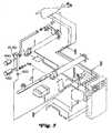
- FIGS. 4 and 5show the multistage blowdown valve used with a dual stage compressor system 1002 .
- the dual stage compressor system 1002 described hereinis best described in U.S. patent application Ser. No. 09/179,523.
- the multistage blowdown valve 10can have many applications and be used with many compressor systems.
- the compressor system 1002 described hereinis merely given as an example and not meant to be limiting.
- the first-stage compressor 102compresses the air to approximately thirty (30) psi.
- the compressed airis transmitted from the first stage compressor 102 into the innerstage piping 104 .
- the compressed airflows through the piping 104 to an innerstage cooler 106 .
- the cooler 106drops the air temperature by approximately three hundred degrees Fahrenheit (300° F).
- the cooler 106is connected to the discharge of the first stage compressor 102 via a coupling plate 108 .
- the compressed airis transmitted through the innerstage cooler 106 into another innerstage pipe 112 .
- the pipe 112is connected to a moisture trap 110 via coupling plates 108 A.
- the moisture trap 110is connected to the innerstage piping that leads to the second stage compressor 114 via innerstage pipe 116 which is also connected to the moisture trap 110 via coupling plates 108 B.
- This compressed airis transmitted into the inlet of the second stage compressor 114 .
- the second stage compressor 114compresses the air approximately another seventy (70) psi, which brings the air up to approximately one hundred (100) psi.
- the compressed airis transmitted from the second stage compressor 114 into the second stage compressor discharge pipe 118 .
- the pipe 118is connected to another discharge pipe 118 A leading to a compressor package discharge cooler 120 .
- the cooler 120again drops the temperature of the compressed air transmitted therethrough by approximately three hundred degrees Fahrenheit (300° F).
- Innerstage pipe 116has a bung 150 welded thereto, which connects the innerstage pipe 116 to the inlet port 26 of the multistage blowdown valve 10 .
- the connection to inlet port 26is through a pipe elbow 151 , pipe nipple 152 , pipe coupling 153 , and pipe nipple 154 .
- a muffler 450is attached to the discharge port 28 of the blowdown valve 10 . The purpose of the muffler 450 is to reduce the amount of noise that would be created when any trapped air pressure is vented to atmosphere.
- Discharge pipe 130 Bis attached to the moisture trap 126 , has a T shaped bung 170 A welded thereto, and has a package temperature probe 2010 is located within it.
- One end of the T-shaped bung 170 Ahas one end of a pipe elbow 128 A coupled thereto.
- the other end of the pipe elbow 128 Ais coupled to the discharge pipe 130 A.
- a pipe nipple 171is connected to the other end of the bung 170 A, which is threaded onto a coupling 172 , which is connected to pipe nipple 173 .
- the inlet port 30 of the multistage blowdown valve 10is connected to the pipe nipple 173 .
- the discharge port 32 of valve 10has an exhaust muffler 440 operatively connected thereto. The muffler 440 reduces the amount of noise created when any trapped air pressure is vented to atmosphere.
- the multistage blowdown valve 10 of the present inventionwill exhaust any trapped pressure at shutdown or unload of the two stage compressor 1002 that might be trapped in innerstage pipe 116 and in the discharge piping 130 B from the second stage compressor 114 . Due to the integration of the interstage and second stage blowdown valves, the interstage and the second stage will be decompressed simultaneously. Therefore, if the second stage blowdown valve malfunctions and fails to open, the innerstage blowdown valve will remain open thus averting possible compressor failure.
- Tubing elbow 180which was attached to the moisture trap 126 , is now attached to a shuttle check valve 492 .
- One side of the shuttle check valve 492is connected to the moisture trap 126 through a pipe fitting 494 .
- the other side of the shuttle check valve 492is connected to a tubing elbow 490 which is connected to tubing 488 .
- Tubing 488has an elbow 480 connected to its other end which is connected to a first end of tubing T 460 .
- tube fitting 190was operatively connected to check valve 128 A, but is now connected to a second end of tubing T 460 .
- the third end of tubing T 460is connected through a pipe fitting 470 to check valve 128 A.
- the dual blowdown valve 10 , 50 of the present inventionlowers the pressure ratio across the second stage, i.e., the value of the pressure across the second stage minus the pressure across the interstage, divided by the value of the pressure across the interstage.
- One of the benefits of maintaining a low-pressure ratio across the second stage compressor during normal operationsis that it lowers operating temperatures in the second stage compressor.
- Tests of the dual blowdown concepthave shown that a standard blowdown system had a second stage compressor discharge as high as 360 degrees F during normal cycling operation. Under the same cycling operation the dual blowdown system had a maximum second stage compressor discharge temperature of 295 degrees F. In this test, the dual blowdown system ran 22 percent cooler than the standard system.
Landscapes
- Engineering & Computer Science (AREA)
- Mechanical Engineering (AREA)
- General Engineering & Computer Science (AREA)
- Compressor (AREA)
- Multiple-Way Valves (AREA)
- Structures Of Non-Positive Displacement Pumps (AREA)
Abstract
Description
Claims (5)
Priority Applications (2)
| Application Number | Priority Date | Filing Date | Title |
|---|---|---|---|
| US09/892,587US6371731B2 (en) | 1997-10-28 | 2001-06-27 | Multistage blowdown valve for a compressor system |
| US10/022,920US6478546B2 (en) | 1997-10-28 | 2001-12-18 | Multistage blowdown valve for a compressor system |
Applications Claiming Priority (4)
| Application Number | Priority Date | Filing Date | Title |
|---|---|---|---|
| US6600897P | 1997-10-28 | 1997-10-28 | |
| US09/179,523US6102665A (en) | 1997-10-28 | 1998-10-27 | Compressor system and method and control for same |
| US09/422,284US6283716B1 (en) | 1997-10-28 | 1999-10-21 | Multistage blowdown valve for a compressor system |
| US09/892,587US6371731B2 (en) | 1997-10-28 | 2001-06-27 | Multistage blowdown valve for a compressor system |
Related Parent Applications (1)
| Application Number | Title | Priority Date | Filing Date |
|---|---|---|---|
| US09/422,284ContinuationUS6283716B1 (en) | 1997-10-28 | 1999-10-21 | Multistage blowdown valve for a compressor system |
Related Child Applications (1)
| Application Number | Title | Priority Date | Filing Date |
|---|---|---|---|
| US10/022,920ContinuationUS6478546B2 (en) | 1997-10-28 | 2001-12-18 | Multistage blowdown valve for a compressor system |
Publications (2)
| Publication Number | Publication Date |
|---|---|
| US20010036408A1 US20010036408A1 (en) | 2001-11-01 |
| US6371731B2true US6371731B2 (en) | 2002-04-16 |
Family
ID=27370902
Family Applications (3)
| Application Number | Title | Priority Date | Filing Date |
|---|---|---|---|
| US09/422,284Expired - Fee RelatedUS6283716B1 (en) | 1997-10-28 | 1999-10-21 | Multistage blowdown valve for a compressor system |
| US09/892,587Expired - Fee RelatedUS6371731B2 (en) | 1997-10-28 | 2001-06-27 | Multistage blowdown valve for a compressor system |
| US10/022,920Expired - Fee RelatedUS6478546B2 (en) | 1997-10-28 | 2001-12-18 | Multistage blowdown valve for a compressor system |
Family Applications Before (1)
| Application Number | Title | Priority Date | Filing Date |
|---|---|---|---|
| US09/422,284Expired - Fee RelatedUS6283716B1 (en) | 1997-10-28 | 1999-10-21 | Multistage blowdown valve for a compressor system |
Family Applications After (1)
| Application Number | Title | Priority Date | Filing Date |
|---|---|---|---|
| US10/022,920Expired - Fee RelatedUS6478546B2 (en) | 1997-10-28 | 2001-12-18 | Multistage blowdown valve for a compressor system |
Country Status (1)
| Country | Link |
|---|---|
| US (3) | US6283716B1 (en) |
Families Citing this family (5)
| Publication number | Priority date | Publication date | Assignee | Title |
|---|---|---|---|---|
| US6283716B1 (en) | 1997-10-28 | 2001-09-04 | Coltec Industries Inc. | Multistage blowdown valve for a compressor system |
| US6854735B2 (en)* | 2002-08-26 | 2005-02-15 | General Electric Company | In situ load sharing brush seals |
| US6769880B1 (en) | 2002-09-19 | 2004-08-03 | Mangonel Corporation | Pressure blowdown system for oil injected rotary screw air compressor |
| JP7384860B2 (en)* | 2021-06-28 | 2023-11-21 | 本田技研工業株式会社 | Depressurization system and method |
| CN119084651A (en)* | 2024-07-29 | 2024-12-06 | 湖南华菱涟源钢铁有限公司 | A descaling machine drain valve |
Citations (23)
| Publication number | Priority date | Publication date | Assignee | Title |
|---|---|---|---|---|
| US3260444A (en) | 1964-03-30 | 1966-07-12 | Gardner Denver Co | Compressor control system |
| US3756753A (en) | 1970-07-16 | 1973-09-04 | Svenska Rotor Maskiner Ab | Two stage screw rotor machines |
| US3927708A (en)* | 1974-01-28 | 1975-12-23 | Clement E Hulme | Automatic tire pressure control |
| US3936239A (en) | 1974-07-26 | 1976-02-03 | Dunham-Bush, Inc. | Undercompression and overcompression free helical screw rotary compressor |
| US4076468A (en) | 1970-07-09 | 1978-02-28 | Svenska Rotor Maskiner Aktiebolag | Multi-stage screw compressor interconnected via communication channel in common end plate |
| US4084618A (en)* | 1972-05-03 | 1978-04-18 | Cmi Corporation | Spool valve |
| US4105064A (en)* | 1976-11-08 | 1978-08-08 | Carrier Corporation | Two stage compressor heating |
| US4155535A (en)* | 1977-03-09 | 1979-05-22 | The Johns Hopkins University | Low axial force servo valve spool |
| US4339233A (en)* | 1979-12-13 | 1982-07-13 | Krueger Wallace F | Power-assisted valve |
| US4646785A (en)* | 1981-03-18 | 1987-03-03 | Manfred Ruedle | Spool valve |
| US4678406A (en) | 1986-04-25 | 1987-07-07 | Frick Company | Variable volume ratio screw compressor with step control |
| US5044894A (en) | 1990-11-30 | 1991-09-03 | Carrier Corporation | Capacity volume ratio control for twin screw compressors |
| US5163478A (en)* | 1990-08-31 | 1992-11-17 | Festo Kg | Spool valve having improved sealing characteristics |
| US5332696A (en) | 1990-10-25 | 1994-07-26 | Hyundai Electronics Industries Co., Ltd. | Method for manufacturing a silicon layer having increased surface area |
| US5335696A (en)* | 1993-03-10 | 1994-08-09 | Fluoroware, Inc. | Three-way weir style valve |
| US5655379A (en)* | 1995-10-27 | 1997-08-12 | General Electric Company | Refrigerant level control in a refrigeration system |
| US5713724A (en)* | 1994-11-23 | 1998-02-03 | Coltec Industries Inc. | System and methods for controlling rotary screw compressors |
| US5738497A (en) | 1996-02-02 | 1998-04-14 | Hensley; Paul D. | Apparatus and method for controlling a rotary screw compressor |
| US5833925A (en)* | 1996-11-13 | 1998-11-10 | Beckman Instruments, Inc. | Automatic chemistry analyzer with improved ion selective electrode assembly |
| US5860801A (en) | 1994-11-30 | 1999-01-19 | Svenska Rotor Maskiner Ab | Rotary screw compressor with unloading means |
| US6053421A (en)* | 1998-05-19 | 2000-04-25 | Caterpillar Inc. | Hydraulically-actuated fuel injector with rate shaping spool control valve |
| US6102665A (en)* | 1997-10-28 | 2000-08-15 | Coltec Industries Inc | Compressor system and method and control for same |
| US6283716B1 (en) | 1997-10-28 | 2001-09-04 | Coltec Industries Inc. | Multistage blowdown valve for a compressor system |
- 1999
- 1999-10-21USUS09/422,284patent/US6283716B1/ennot_activeExpired - Fee Related
- 2001
- 2001-06-27USUS09/892,587patent/US6371731B2/ennot_activeExpired - Fee Related
- 2001-12-18USUS10/022,920patent/US6478546B2/ennot_activeExpired - Fee Related
Patent Citations (23)
| Publication number | Priority date | Publication date | Assignee | Title |
|---|---|---|---|---|
| US3260444A (en) | 1964-03-30 | 1966-07-12 | Gardner Denver Co | Compressor control system |
| US4076468A (en) | 1970-07-09 | 1978-02-28 | Svenska Rotor Maskiner Aktiebolag | Multi-stage screw compressor interconnected via communication channel in common end plate |
| US3756753A (en) | 1970-07-16 | 1973-09-04 | Svenska Rotor Maskiner Ab | Two stage screw rotor machines |
| US4084618A (en)* | 1972-05-03 | 1978-04-18 | Cmi Corporation | Spool valve |
| US3927708A (en)* | 1974-01-28 | 1975-12-23 | Clement E Hulme | Automatic tire pressure control |
| US3936239A (en) | 1974-07-26 | 1976-02-03 | Dunham-Bush, Inc. | Undercompression and overcompression free helical screw rotary compressor |
| US4105064A (en)* | 1976-11-08 | 1978-08-08 | Carrier Corporation | Two stage compressor heating |
| US4155535A (en)* | 1977-03-09 | 1979-05-22 | The Johns Hopkins University | Low axial force servo valve spool |
| US4339233A (en)* | 1979-12-13 | 1982-07-13 | Krueger Wallace F | Power-assisted valve |
| US4646785A (en)* | 1981-03-18 | 1987-03-03 | Manfred Ruedle | Spool valve |
| US4678406A (en) | 1986-04-25 | 1987-07-07 | Frick Company | Variable volume ratio screw compressor with step control |
| US5163478A (en)* | 1990-08-31 | 1992-11-17 | Festo Kg | Spool valve having improved sealing characteristics |
| US5332696A (en) | 1990-10-25 | 1994-07-26 | Hyundai Electronics Industries Co., Ltd. | Method for manufacturing a silicon layer having increased surface area |
| US5044894A (en) | 1990-11-30 | 1991-09-03 | Carrier Corporation | Capacity volume ratio control for twin screw compressors |
| US5335696A (en)* | 1993-03-10 | 1994-08-09 | Fluoroware, Inc. | Three-way weir style valve |
| US5713724A (en)* | 1994-11-23 | 1998-02-03 | Coltec Industries Inc. | System and methods for controlling rotary screw compressors |
| US5860801A (en) | 1994-11-30 | 1999-01-19 | Svenska Rotor Maskiner Ab | Rotary screw compressor with unloading means |
| US5655379A (en)* | 1995-10-27 | 1997-08-12 | General Electric Company | Refrigerant level control in a refrigeration system |
| US5738497A (en) | 1996-02-02 | 1998-04-14 | Hensley; Paul D. | Apparatus and method for controlling a rotary screw compressor |
| US5833925A (en)* | 1996-11-13 | 1998-11-10 | Beckman Instruments, Inc. | Automatic chemistry analyzer with improved ion selective electrode assembly |
| US6102665A (en)* | 1997-10-28 | 2000-08-15 | Coltec Industries Inc | Compressor system and method and control for same |
| US6283716B1 (en) | 1997-10-28 | 2001-09-04 | Coltec Industries Inc. | Multistage blowdown valve for a compressor system |
| US6053421A (en)* | 1998-05-19 | 2000-04-25 | Caterpillar Inc. | Hydraulically-actuated fuel injector with rate shaping spool control valve |
Also Published As
| Publication number | Publication date |
|---|---|
| US6478546B2 (en) | 2002-11-12 |
| US20020051708A1 (en) | 2002-05-02 |
| US20010036408A1 (en) | 2001-11-01 |
| US6283716B1 (en) | 2001-09-04 |
Similar Documents
| Publication | Publication Date | Title |
|---|---|---|
| US6913448B2 (en) | Load-regulating device for scroll type compressors | |
| CA2161907A1 (en) | Valve system for capacity control of a screw compressor and method of manufacturing such valves | |
| US5807081A (en) | Combination valve for screw compressors | |
| US20030019211A1 (en) | Hydraulic pressure booster cylinder | |
| US5127386A (en) | Apparatus for controlling a supercharger | |
| US3448916A (en) | Unloading system for compressors | |
| WO2005050107A3 (en) | Tandem compressors with discharge valve on connecting lines | |
| US6371731B2 (en) | Multistage blowdown valve for a compressor system | |
| US4470428A (en) | Unloader and check valve | |
| US9353741B2 (en) | Compressor throttling valve assembly | |
| KR101002534B1 (en) | Compressor | |
| KR101012946B1 (en) | Multistage gas compression device | |
| US20240061454A1 (en) | Pneumatic inlet/blowdown valve assembly | |
| US6776588B1 (en) | Dry compressing vacuum pump having a gas ballast device | |
| US3503223A (en) | Refrigeration system having tandem compressor arrangement | |
| US12398721B2 (en) | Gas operated infinite step valve for a reciprocating compressor | |
| CA2323389A1 (en) | Multistage blowdown valve for a compressor system | |
| CN112049769B (en) | Piston compressor and refrigeration equipment | |
| JP2006509171A (en) | Super high pressure check valve | |
| US4834631A (en) | Separator and biasing plate | |
| US4711617A (en) | Rotary compressor | |
| WO2024066312A1 (en) | Pump body assembly, compressor assembly, and air conditioning system | |
| SE9803292D0 (en) | Screw rotary compressor lifting valve | |
| US10156233B2 (en) | Dual control valve for reciprocating compressor unloader system | |
| CN111946598B (en) | A centralized unloading device with multiple pump heads for air compressor units |
Legal Events
| Date | Code | Title | Description |
|---|---|---|---|
| AS | Assignment | Owner name:BANK OF AMERICA, N.A. AS AGENT, GEORGIA Free format text:SECURITY INTEREST;ASSIGNOR:COLTEC INDUSTRIES, INC.;REEL/FRAME:013269/0584 Effective date:20020531 | |
| FPAY | Fee payment | Year of fee payment:4 | |
| FPAY | Fee payment | Year of fee payment:8 | |
| AS | Assignment | Owner name:COLTEC INDUSTRIES INC (A/K/A COLTEC INDUSTRIES, IN Free format text:RELEASE BY SECURED PARTY;ASSIGNOR:BANK OF AMERICA, N.A., AS COLLATERAL AND ADMINISTRATIVE AGENT;REEL/FRAME:024016/0484 Effective date:20100302 Owner name:FULCRUM ACQUISITION LLC,NEW JERSEY Free format text:ASSIGNMENT OF ASSIGNORS INTEREST;ASSIGNOR:COLTEC INDUSTRIES INC (A/K/A COLTEC INDUSTRIES, INC.);REEL/FRAME:024016/0595 Effective date:20100301 Owner name:FULCRUM ACQUISITION LLC, NEW JERSEY Free format text:ASSIGNMENT OF ASSIGNORS INTEREST;ASSIGNOR:COLTEC INDUSTRIES INC (A/K/A COLTEC INDUSTRIES, INC.);REEL/FRAME:024016/0595 Effective date:20100301 | |
| AS | Assignment | Owner name:QUINCY COMPRESSOR LLC,NEW JERSEY Free format text:CHANGE OF NAME;ASSIGNOR:FULCRUM ACQUISITION LLC;REEL/FRAME:024035/0380 Effective date:20100301 Owner name:QUINCY COMPRESSOR LLC, NEW JERSEY Free format text:CHANGE OF NAME;ASSIGNOR:FULCRUM ACQUISITION LLC;REEL/FRAME:024035/0380 Effective date:20100301 | |
| REMI | Maintenance fee reminder mailed | ||
| LAPS | Lapse for failure to pay maintenance fees | ||
| STCH | Information on status: patent discontinuation | Free format text:PATENT EXPIRED DUE TO NONPAYMENT OF MAINTENANCE FEES UNDER 37 CFR 1.362 | |
| FP | Lapsed due to failure to pay maintenance fee | Effective date:20140416 | |
| AS | Assignment | Owner name:QUINCY COMPRESSOR LLC, ALABAMA Free format text:CHANGE OF ADDRESS;ASSIGNOR:QUINCY COMPRESSOR LLC;REEL/FRAME:052204/0023 Effective date:20200321 |