US6371267B1 - Liquid cooled magnetorheological fluid clutch for automotive transmissions - Google Patents
Liquid cooled magnetorheological fluid clutch for automotive transmissionsDownload PDFInfo
- Publication number
- US6371267B1 US6371267B1US09/706,392US70639200AUS6371267B1US 6371267 B1US6371267 B1US 6371267B1US 70639200 AUS70639200 AUS 70639200AUS 6371267 B1US6371267 B1US 6371267B1
- Authority
- US
- United States
- Prior art keywords
- channels
- housing
- magnetic core
- channel ring
- channel
- Prior art date
- Legal status (The legal status is an assumption and is not a legal conclusion. Google has not performed a legal analysis and makes no representation as to the accuracy of the status listed.)
- Expired - Lifetime
Links
Images


Classifications
- F—MECHANICAL ENGINEERING; LIGHTING; HEATING; WEAPONS; BLASTING
- F16—ENGINEERING ELEMENTS AND UNITS; GENERAL MEASURES FOR PRODUCING AND MAINTAINING EFFECTIVE FUNCTIONING OF MACHINES OR INSTALLATIONS; THERMAL INSULATION IN GENERAL
- F16D—COUPLINGS FOR TRANSMITTING ROTATION; CLUTCHES; BRAKES
- F16D13/00—Friction clutches
- F16D13/58—Details
- F16D13/72—Features relating to cooling
- F—MECHANICAL ENGINEERING; LIGHTING; HEATING; WEAPONS; BLASTING
- F16—ENGINEERING ELEMENTS AND UNITS; GENERAL MEASURES FOR PRODUCING AND MAINTAINING EFFECTIVE FUNCTIONING OF MACHINES OR INSTALLATIONS; THERMAL INSULATION IN GENERAL
- F16D—COUPLINGS FOR TRANSMITTING ROTATION; CLUTCHES; BRAKES
- F16D25/00—Fluid-actuated clutches
- F16D25/12—Details not specific to one of the before-mentioned types
- F16D25/123—Details not specific to one of the before-mentioned types in view of cooling and lubrication
- F—MECHANICAL ENGINEERING; LIGHTING; HEATING; WEAPONS; BLASTING
- F16—ENGINEERING ELEMENTS AND UNITS; GENERAL MEASURES FOR PRODUCING AND MAINTAINING EFFECTIVE FUNCTIONING OF MACHINES OR INSTALLATIONS; THERMAL INSULATION IN GENERAL
- F16D—COUPLINGS FOR TRANSMITTING ROTATION; CLUTCHES; BRAKES
- F16D37/00—Clutches in which the drive is transmitted through a medium consisting of small particles, e.g. centrifugally speed-responsive
- F16D37/02—Clutches in which the drive is transmitted through a medium consisting of small particles, e.g. centrifugally speed-responsive the particles being magnetisable
- F—MECHANICAL ENGINEERING; LIGHTING; HEATING; WEAPONS; BLASTING
- F16—ENGINEERING ELEMENTS AND UNITS; GENERAL MEASURES FOR PRODUCING AND MAINTAINING EFFECTIVE FUNCTIONING OF MACHINES OR INSTALLATIONS; THERMAL INSULATION IN GENERAL
- F16D—COUPLINGS FOR TRANSMITTING ROTATION; CLUTCHES; BRAKES
- F16D37/00—Clutches in which the drive is transmitted through a medium consisting of small particles, e.g. centrifugally speed-responsive
- F16D2037/004—Clutches in which the drive is transmitted through a medium consisting of small particles, e.g. centrifugally speed-responsive characterised by multiple substantially axial gaps in which the fluid or medium consisting of small particles is arranged
Definitions
- This inventionrelates to fluid clutches and, more particularly, to magnetorheological fluid clutches having liquid cooling.
- Magnetorheological fluid clutcheshave been proposed for various applications requiring a torque responsive control, such as engine cooling fan clutches. More recently, the magnetorheological fluid clutches have been proposed as transmission clutches replacing conventional torque converters as a starting clutch or launch device.
- a magnetorheological fluidis a suspension of finely powdered magnetizable solids, such as iron or iron alloy, in a suitable fluid medium such as mineral oil, synthetic oil or silicone.
- a magnetorheological fluid clutchmay consist of this type of fluid suspension carried between clutch plates with an associated device providing a desired magnetic flux level across the clutch plates and the fluid.
- the clutch platesare typically made of a material with high magnetic permeability such as iron.
- the MRCwhen used as a launch device, is required to transmit considerably more power than when used as a fan clutch.
- the MRCwhen used as a launch device, can generate a considerable amount of heat that must be expelled from the clutch assembly.
- the MRC launch devicerelies heavily on air cooling to dissipate the heat generated within it. This limits the size and power capacity of the MRC unless extraordinary methods of cooling air volumes is undertaken. Such increases in air flow result in larger air cooling chambers and large capacity fans or air pumps to provide the air flow volumes necessary to provide the required cooling.
- prior art application of the MRC as a vehicle launch devicehave been limited to low-displacement engine (approximately 1.3 L) powertrains.
- a MRChas a coolant inlet port and a coolant outlet port surrounding the output shaft for the MRC.
- a front magnetic core and a rear magnetic coreare assembled to contain an encapsulated electromagnetic coil and provided with passages for supplying liquid coolant to and from the coil.
- a rear magnetic core and a coolant channel ringhave a plurality of axial flow paths that direct liquid coolant toward the encapsulated magnetic coil.
- a plurality of radial flow pathsare formed in the housing and coolant channel ring to direct liquid coolant in a serpentine path from the inlet port, over an outer surface of the outer magnetic core, to the outlet port.
- flow paths for the liquid cooling mediumare formed in the clutch housing, the coolant channel ring, and the rear core.
- a flow divider plateis secured radially inward of the rear core and the channel ring to direct coolant liquid from the inlet port toward radial flow paths in the clutch housing.
- the flow channel ringis secured to the rear core and has formed therein a plurality of flow paths to direct the liquid coolant from axial flow paths, formed between the housing and the outer magnetic core, to the divider plate and the outlet port.
- the divider plateprevents the intermingling of the inlet coolant flow and the outlet coolant flow.
- a portion of the liquid inlet flow in the housing channelsis directed to flow past the encapsulated coil and return to join the outlet flow from the flow channel ring at the divider plate.
- the magnetorheological clutch assemblyprovides torque transfer between an input member and an output member through the contained magnetorheological fluid.
- an encapsulated coilWhen an encapsulated coil is supplied with electrical current from an external source that communicates with the magnetorheological clutch through a conventional interface such as slip rings, an electromagnetic field is established.
- the magnetic fieldpasses through the input and output members and across the magnetorheological fluid in a cavity which is disposed in working gaps between the input and output members.
- the magnetic fieldprovides the necessary coupling in an energy transfer process between the input member and the output member.
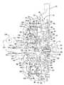
- FIG. 1is an elevational view of a magnetorheological fluid clutch incorporating the present invention.
- FIG. 2is an isometric cut-away view of a portion of the magnetorheological clutch shown in FIG. 1 .
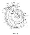
- FIG. 3is a view taken along line 3 — 3 in FIG. 1 .
- FIG. 4is a view taken along line 4 — 4 in FIG. 1 .
- FIG. 5is a view taken along line 5 — 5 in FIG. 1 .
- FIG. 6is a view taken along line 6 — 6 in FIG. 1 .
- FIG. 7is a plan view taken along line 7 — 7 in FIG. 3 .
- a magnetorheological clutch (MRC) assembly 10has an input member 12 , connected with an engine 14 , and an output shaft 16 .
- the input member 12includes a flex-plate 18 , a drive plate 20 and a labyrinth plate 22 .
- the flex-plate 18is secured to the engine 14 by fasteners 24 .
- the drive plate 20is secured between the flex-plate 18 and the labyrinth plate 22 by fasteners 26 and 28 , respectively.
- the output shaft 16is connected with a drive sprocket 29 that is drivingly connected with a conventional power transmission through a chain drive, not shown.
- the labyrinth plate 22is secured to an input rotor 30 that is rotatably disposed between an outer magnetic core 32 and an inner magnetic core 34 .
- the input rotor 30is separated from the outer magnetic core 32 and the inner magnetic core 34 by respective annular working gaps 36 and 38 .
- the outer magnetic core 32has a side plate or cover 40 secured thereto, which cover 40 has an inner annular portion 42 in which a seal 44 is secured and disposed to sealingly engage an annular hub 46 formed on the labyrinth plate 22 .
- the inner magnetic core 34includes a rear core member 48 and a front core member 50 that are secured together by fasteners, not shown.
- An annular encapsulated coil 52is secured in an annular channel 54 formed between the front core member 50 and the rear core member 48 .
- the coil 52is encapsulated in a non-ferrous abrasion-resistant material such as Zenite, so that the front and rear core members 50 and 48 and the magnetorheologic fluid that is circulated in the working gaps 36 and 38 of the clutch 10 will not abrade the wires of the coil 52 .
- a non-ferrous abrasion-resistant materialsuch as Zenite
- Magnetorheological fluidscomprising a suspension of solid particles in a selected liquid are known wherein the fluid's yield stress must be exceeded in order to initiate flow.
- the flow threshold yield stressincreases as the flux density in the field increases.
- Yield stressis also known to increase as the volume fraction of solid particles in the suspension is increased. Accordingly, a desired yield stress for a selected MRF operating in a clutch can be achieved by controlling the volume fraction of suspended particles.
- Magnetorheological fluids useful as in the present inventionare described in detail by commonly assigned U.S. Pat. No. 5,667,715 entitled “Magnetorheological Fluids,” issued Oct. 20, 1998, and which is specifically incorporated herein by reference.
- the MRFis disposed in the working gaps 36 and 38 . Due to the viscous nature of the MRF, it will generally remain in the working gaps when the clutch is not rotating.
- the magnetorheological fluidcarries a selected volume percent of solid particles that permits slippage between the input rotor 30 and the output member, comprised of the outer and inner magnetic cores 32 and 34 , when the MRC 10 is partially engaged during acceleration and transmission shifting events.
- An increased torque transferis effected between input and output members as the MRC 10 is engaged through energizing the encapsulated coil 52 , and substantially complete coupling is provided when the MRC 10 is fully engaged with negligible slippage between the input and output members.
- the front core member 50has a bearing plate 56 secured thereto and rotatably supported by a bearing 58 that is disposed between a shaft extension 60 of the input member 12 and the bearing plate 56 .
- the cover 40 and the bearing plate 56cooperate to form a space or reservoir 57 in which any magnetorheological fluid that is not disposed in the working gaps 36 and 38 is contained.
- the cover 40 and the bearing plate 56have respective annular troughs 62 and 64 which cooperate with respective annular troughs 66 and 68 formed on the labyrinth plate 22 to form labyrinth passages in the reservoir 57 .
- magnetorheological fluidWhile the magnetorheological fluid is viscous and resistant to flow, when the MRC 10 is at rest, some of the magnetorheological fluid may leave the working gaps 36 , 38 . This fluid will progress along the walls of either the cover 40 , the bearing plate 56 , or the labyrinth plate 22 and encounter the annular labyrinth passages formed by the troughs 62 , 64 , 66 , and 68 and from there be directed to the lowest portion of the reservoir 57 . This will maintain the magnetorheological fluid out of contact with the seal 44 and a seal 72 disposed between the bearing plate 56 and the shaft extension 60 .
- the outer core 32 and the rear core 48are secured for common rotation by a channel ring 74 , a spring damper 76 and a housing 78 .
- the housing 78is secured to the cover 40 to substantially enclose the input rotor 30 and the magnetic cores 32 , 48 and 50 .
- the spring damper 76is drivingly connected through a spline 80 with the output shaft 16 and, as previously described, the rotor 30 is drivingly connected with the engine 14 .
- the encapsulated coil 52is connected by electrical conductors or wires 82 and 84 with a conventional slip ring assembly 86 which in turn is connected with the electrical system of a vehicle, not shown.
- the encapsulated coil 52when energized, creates a magnetic field which causes the magnetorheological fluid to become more viscous as the field intensity increases, thereby establishing a magnetorheological drive relationship between the rotor 30 and the cores 32 , 48 and 50 .
- the magnetorheological clutch assembly 10when energized, will transmit engine power to the output shaft 16 .
- the rear core 48has a plurality of axially extending passages 88 that intersect the annular channel 54 and an inner surface 90 of the channel ring 74 .
- the interface between the front core 50 and the rear core 48has formed therein a plurality of radial passages 92 that intersect the annular channel 54 and the radially inner periphery 96 of the rear core 48 .
- These passages 88 and 92direct cooling fluid, as will be explained later, through the annular channel 54 to provide cooling of the encapsulated coil 52 .
- a clutch hub 98has a sleeve portion 99 that is rotatably supported on a shaft 100 that is secured to the clutch housing 70 .
- the slip ring 86is mounted on the sleeve portion 99 and has an outer portion 102 that is connected with the housing 70 .
- Electrical connections, not shown,are arranged between the housing 70 and the stationary portion 102 to permit the distribution of electrical energy to the encapsulated coil 52 .
- the clutch hub 98has a radially extending annular portion 104 that is secured to the housing 78 . As best seen in FIG.
- the annular portion 104has a plurality of equiangularly-spaced channels 106 that extend radially from the sleeve portion 99 to a space 108 formed between the hub 98 and a flow divider plate 110 .
- the sleeve portion 99has a plurality of axially extending passages 112 that communicate from a space 114 , between the shaft 100 and the sleeve portion 99 , to the inner edge of the channels 106 .
- the channels 106communicate with a plurality of equiangularly-spaced, radially-extending channels 116 formed in the housing 78 .
- One or more of the channels 116communicate respectively with the passages 88 to provide cooling fluid to the encapsulated coil 52 .
- the fluid in the passages 88flows through the slots 117 , formed at the inner surface of the encapsulated coil 52 (see FIG. 4 ), to the passage 92 .
- the space 114is in fluid communication through passages 118 , passages 120 , annular space 122 , and passages 124 with a source of hydraulic fluid such as a conventional pump 126 that is driven by a pump shaft 129 , which is drivingly connected with the shaft extension 60 .
- the pump 126supplies fluid from a transmission sump or reservoir 127 for control function, lubrication and cooling to a transmission, not shown, as well as cooling fluid for the clutch assembly.
- the channels 116communicate with a circumferential space 128 formed between the housing 78 and the outer core 32 .
- the circumferential space 128is interrupted by weirs 130 that extend axially across a considerable portion of the inner surface 132 of an outer rim 134 of the housing 78 and closely fit with an outer surface 136 of the outer core 32 to provide a narrow circumferential channel 138 between the core 32 and the cover 78 . Every other circumferential channel 138 is interrupted by a plurality of weirs 140 formed on the outer core 32 .
- the weirs 130direct cooling fluid axially through the space 128 (Arrow A), circumferentially in the channel 138 (Arrow B), and axially through the space 128 (Arrow C).
- the channel ring 74has a plurality of radially extending channels 142 formed in an outer surface 144 (see FIG. 6) that is disposed in abutment with the housing 78 .
- the channels 142communicate with ports 146 formed in the channel ring 74 .
- the ports 146each communicate with a respective radially extending channel 148 formed in the inner surface 90 (see FIG. 5 ).
- the channels 142communicate with the space 128 equidistant between intermediate sequentially-spaced weirs 130 (see FIGS. 6 and 7 ).
- the fluid entering channel 142flows inwardly (Arrow D) through the ports 146 into the channels 148 (Arrow E), see FIG. 2 .
- the channels 148communicate cooling fluid with a space 150 formed between the divider plate 110 and the spring damper 76 .
- the cooling fluid flow from the space 150 surrounding the spring damper 76flows axially in an annular space 151 along the pump shaft 129 to a coolant outlet port 152 which is in fluid communication with the hydraulic fluid reservoir 127 .
- the cooling fluid that flows through the annular channel 54 and the passage 92also returns to the reservoir via this path.
- the electrical conductors 82 and 84pass through respective passages 88 and respective fittings 154 .
- the fittings 154are secured in the housing 78 at diametrically opposed locations. Only one of the fittings is shown in FIG. 1 .
- the fitting 154has conventional sealing material surrounding the conductor 82 that prevents the fluid in passage 88 from escaping to atmosphere.
- the cover 78also has a plurality of fill openings 156 that are aligned with the working gaps 36 and 38 . These openings 156 permit the introduction of MRF into the working gaps at assembly.
- the openings 156are closed and sealed with plugs 158 to prevent the leakage of the MRF.
- the encapsulated coil 52is energized by a conventional electrical source, not shown, in accordance with a command signal from a conventional engine control module or transmission control module, not shown.
- the control modulesare preferably components of a conventional electronic control unit, not shown, that includes a programmable digital computer. These controls are well known to those skilled in the art.
- the encapsulated coil 52produces a magnetic field, proportional to the electric current delivered thereto, which encompasses the outer magnetic core 32 and the inner magnetic core 34 .
- the magnetic fieldthus established causes the particles in the MRF in the working gaps 36 and 38 to become more aligned and increases the viscosity of the MRF such that the torque capacity of the MRC 10 is increased.
- the engine poweris transmitted to the output shaft 16 , sprocket 29 and the transmission. As the electrical current is increased, the torque capacity of the MRC 10 is increased to permit a smooth launch of the vehicle similar to a fluid coupling.
- the MRC 10can also be employed as a shifting clutch which is utilized to change ratios within the transmission in a well-known manner.
- the shifting clutchcan be of the rotary type or the stationary type (brake). In both of these applications, the cooling flow paths will be similar.
- the cooling flowwill enter the clutch at the inner periphery and be transported through the channels 106 and 116 to the rim 134 of the housing 78 and to the encapsulated coil 52 .
- the cooling flow at the rim 134 of the housing 78will follow the serpentine path describe by the Arrows A, B, and C in FIG. 7 .
- the cooling flowis then directed inward through the channels 142 and 148 to the inner periphery of the inner magnetic core 34 .
- the cooling flow passing the encapsulated coil 52is commingled with the cooling flow from the channels 148 and returned to the transmission reservoir 127 .
Landscapes
- Engineering & Computer Science (AREA)
- General Engineering & Computer Science (AREA)
- Mechanical Engineering (AREA)
- Hydraulic Clutches, Magnetic Clutches, Fluid Clutches, And Fluid Joints (AREA)
Abstract
Description
Claims (8)
Priority Applications (1)
| Application Number | Priority Date | Filing Date | Title |
|---|---|---|---|
| US09/706,392US6371267B1 (en) | 2000-11-06 | 2000-11-06 | Liquid cooled magnetorheological fluid clutch for automotive transmissions |
Applications Claiming Priority (1)
| Application Number | Priority Date | Filing Date | Title |
|---|---|---|---|
| US09/706,392US6371267B1 (en) | 2000-11-06 | 2000-11-06 | Liquid cooled magnetorheological fluid clutch for automotive transmissions |
Publications (1)
| Publication Number | Publication Date |
|---|---|
| US6371267B1true US6371267B1 (en) | 2002-04-16 |
Family
ID=24837354
Family Applications (1)
| Application Number | Title | Priority Date | Filing Date |
|---|---|---|---|
| US09/706,392Expired - LifetimeUS6371267B1 (en) | 2000-11-06 | 2000-11-06 | Liquid cooled magnetorheological fluid clutch for automotive transmissions |
Country Status (1)
| Country | Link |
|---|---|
| US (1) | US6371267B1 (en) |
Cited By (42)
| Publication number | Priority date | Publication date | Assignee | Title |
|---|---|---|---|---|
| US6637539B2 (en)* | 1999-06-23 | 2003-10-28 | Bombardier Inc. | All terrain vehicle motor with cooling channels |
| EP1418360A1 (en)* | 2002-11-06 | 2004-05-12 | BorgWarner, Inc. | Through flow device for changing the direction of or transmitting pressure of a fluid |
| US6745879B1 (en)* | 2003-02-03 | 2004-06-08 | New Venture Gear, Inc. | Hydromechanical coupling with clutch assembly and magnetorheological clutch actuator |
| US20050061601A1 (en)* | 2003-09-19 | 2005-03-24 | Stefina Brian K. | Variable torsional damper having magneto-rheological fluid damping in parallel with a spring damper |
| WO2005036009A1 (en)* | 2003-10-08 | 2005-04-21 | Ricardo Uk Limited | Clutches including a magneto-rheological fluid |
| US20050188690A1 (en)* | 2003-04-07 | 2005-09-01 | Namuduri Chandra S. | Magneto-rheological hydraulic power steering system |
| US20050230211A1 (en)* | 2004-04-16 | 2005-10-20 | Weilant David R | Hydrodynamic coupling apparatus |
| US20050258090A1 (en)* | 2004-05-21 | 2005-11-24 | Crosby Gernon | An electromagnetic rheological (emr) fluid and method for using the emr fluid |
| US20050274454A1 (en)* | 2004-06-09 | 2005-12-15 | Extrand Charles W | Magneto-active adhesive systems |
| US20060179844A1 (en)* | 2005-02-17 | 2006-08-17 | Verbrugge Mark W | Elecrtric hybrid powertrain system having a magnetorheological fluid clutch |
| US7416062B1 (en) | 2003-10-23 | 2008-08-26 | The United States Of America As Represented By The Administrator Of The National Aeronautics And Space Administration | Torsional magnetorheological device |
| US20110278123A1 (en)* | 2004-04-01 | 2011-11-17 | Behr America, Inc. | Clutch assembly |
| US20150115563A1 (en)* | 2009-10-13 | 2015-04-30 | Fox Factory, Inc. | Methods and apparatus for controlling a fluid damper |
| JP2015183846A (en)* | 2014-03-26 | 2015-10-22 | ジヤトコ株式会社 | electromagnetic clutch |
| WO2017196601A1 (en)* | 2016-05-09 | 2017-11-16 | Remy Technologies, L.L.C. | Hybrid rotor module cooling |
| CN107448503A (en)* | 2016-05-31 | 2017-12-08 | 法雷奥离合器公司 | Cooling system for clutch mechanism |
| US10036443B2 (en) | 2009-03-19 | 2018-07-31 | Fox Factory, Inc. | Methods and apparatus for suspension adjustment |
| US10040329B2 (en) | 2009-01-07 | 2018-08-07 | Fox Factory, Inc. | Method and apparatus for an adjustable damper |
| US10047817B2 (en) | 2009-01-07 | 2018-08-14 | Fox Factory, Inc. | Method and apparatus for an adjustable damper |
| US10060499B2 (en) | 2009-01-07 | 2018-08-28 | Fox Factory, Inc. | Method and apparatus for an adjustable damper |
| US10072724B2 (en) | 2008-08-25 | 2018-09-11 | Fox Factory, Inc. | Methods and apparatus for suspension lock out and signal generation |
| US10086670B2 (en) | 2009-03-19 | 2018-10-02 | Fox Factory, Inc. | Methods and apparatus for suspension set up |
| US10094443B2 (en) | 2009-01-07 | 2018-10-09 | Fox Factory, Inc. | Bypass for a suspension damper |
| US10160511B2 (en) | 2009-01-07 | 2018-12-25 | Fox Factory, Inc. | Method and apparatus for an adjustable damper |
| US10330171B2 (en) | 2012-05-10 | 2019-06-25 | Fox Factory, Inc. | Method and apparatus for an adjustable damper |
| US10400847B2 (en) | 2009-01-07 | 2019-09-03 | Fox Factory, Inc. | Compression isolator for a suspension damper |
| US10415662B2 (en) | 2009-01-07 | 2019-09-17 | Fox Factory, Inc. | Remotely operated bypass for a suspension damper |
| US10591015B2 (en) | 2009-03-19 | 2020-03-17 | Fox Factory, Inc. | Methods and apparatus for suspension adjustment |
| US10677309B2 (en) | 2011-05-31 | 2020-06-09 | Fox Factory, Inc. | Methods and apparatus for position sensitive suspension damping |
| US10697514B2 (en) | 2010-01-20 | 2020-06-30 | Fox Factory, Inc. | Remotely operated bypass for a suspension damper |
| US10731724B2 (en) | 2009-10-13 | 2020-08-04 | Fox Factory, Inc. | Suspension system |
| US10737546B2 (en) | 2016-04-08 | 2020-08-11 | Fox Factory, Inc. | Electronic compression and rebound control |
| US10821795B2 (en) | 2009-01-07 | 2020-11-03 | Fox Factory, Inc. | Method and apparatus for an adjustable damper |
| CN112253646A (en)* | 2020-10-29 | 2021-01-22 | 重庆理工大学 | Magnetorheological transmission device based on shape memory alloy extrusion bearing bush caused by coil heating |
| US11021204B2 (en) | 2008-11-25 | 2021-06-01 | Fox Factory, Inc. | Seat post |
| US11279199B2 (en) | 2012-01-25 | 2022-03-22 | Fox Factory, Inc. | Suspension damper with by-pass valves |
| US11299233B2 (en) | 2009-01-07 | 2022-04-12 | Fox Factory, Inc. | Method and apparatus for an adjustable damper |
| US11306798B2 (en) | 2008-05-09 | 2022-04-19 | Fox Factory, Inc. | Position sensitive suspension damping with an active valve |
| US11413924B2 (en) | 2009-03-19 | 2022-08-16 | Fox Factory, Inc. | Methods and apparatus for selective spring pre-load adjustment |
| US11499601B2 (en) | 2009-01-07 | 2022-11-15 | Fox Factory, Inc. | Remotely operated bypass for a suspension damper |
| US11866110B2 (en) | 2010-07-02 | 2024-01-09 | Fox Factory, Inc. | Lever assembly for positive lock adjustable seat post |
| US12122205B2 (en) | 2009-01-07 | 2024-10-22 | Fox Factory, Inc. | Active valve for an internal bypass |
Citations (8)
| Publication number | Priority date | Publication date | Assignee | Title |
|---|---|---|---|---|
| JPS52153057A (en)* | 1976-06-15 | 1977-12-19 | Mitsubishi Electric Corp | Magnetic particle type coupling apparatus |
| US5178582A (en)* | 1990-05-31 | 1993-01-12 | Shinko Denki Kabushiki Kaisha | Electromagnetic powder coupling device |
| US5667715A (en) | 1996-04-08 | 1997-09-16 | General Motors Corporation | Magnetorheological fluids |
| US5803219A (en)* | 1995-10-30 | 1998-09-08 | Fuji Jukogyo Kabushiki Kaisha | Cooling mechanism of electromagnetic powder clutch |
| US5823309A (en) | 1997-05-23 | 1998-10-20 | General Motors Corporation | Magnetorheological transmission clutch |
| US5890983A (en)* | 1996-02-05 | 1999-04-06 | Honda Giken Kogyo Kabushiki Kaisha | Cooling apparatus of a gear transmission having an electromagnetic clutch |
| US6032772A (en)* | 1998-09-21 | 2000-03-07 | Behr America, Inc. | Viscous clutch assembly |
| US6318531B1 (en)* | 2000-06-20 | 2001-11-20 | General Motors Corporation | Magnetorheological fluid clutch |
- 2000
- 2000-11-06USUS09/706,392patent/US6371267B1/ennot_activeExpired - Lifetime
Patent Citations (8)
| Publication number | Priority date | Publication date | Assignee | Title |
|---|---|---|---|---|
| JPS52153057A (en)* | 1976-06-15 | 1977-12-19 | Mitsubishi Electric Corp | Magnetic particle type coupling apparatus |
| US5178582A (en)* | 1990-05-31 | 1993-01-12 | Shinko Denki Kabushiki Kaisha | Electromagnetic powder coupling device |
| US5803219A (en)* | 1995-10-30 | 1998-09-08 | Fuji Jukogyo Kabushiki Kaisha | Cooling mechanism of electromagnetic powder clutch |
| US5890983A (en)* | 1996-02-05 | 1999-04-06 | Honda Giken Kogyo Kabushiki Kaisha | Cooling apparatus of a gear transmission having an electromagnetic clutch |
| US5667715A (en) | 1996-04-08 | 1997-09-16 | General Motors Corporation | Magnetorheological fluids |
| US5823309A (en) | 1997-05-23 | 1998-10-20 | General Motors Corporation | Magnetorheological transmission clutch |
| US6032772A (en)* | 1998-09-21 | 2000-03-07 | Behr America, Inc. | Viscous clutch assembly |
| US6318531B1 (en)* | 2000-06-20 | 2001-11-20 | General Motors Corporation | Magnetorheological fluid clutch |
Cited By (97)
| Publication number | Priority date | Publication date | Assignee | Title |
|---|---|---|---|---|
| US6637539B2 (en)* | 1999-06-23 | 2003-10-28 | Bombardier Inc. | All terrain vehicle motor with cooling channels |
| EP1418360A1 (en)* | 2002-11-06 | 2004-05-12 | BorgWarner, Inc. | Through flow device for changing the direction of or transmitting pressure of a fluid |
| US6745879B1 (en)* | 2003-02-03 | 2004-06-08 | New Venture Gear, Inc. | Hydromechanical coupling with clutch assembly and magnetorheological clutch actuator |
| US6811007B2 (en)* | 2003-02-03 | 2004-11-02 | New Venture Gear, Inc. | Hydromechanical coupling with clutch assembly and magnetorheological clutch actuator |
| US7240485B2 (en) | 2003-04-07 | 2007-07-10 | Gm Global Technology Operations, Inc. | Power steering system |
| US20050188690A1 (en)* | 2003-04-07 | 2005-09-01 | Namuduri Chandra S. | Magneto-rheological hydraulic power steering system |
| US20050061601A1 (en)* | 2003-09-19 | 2005-03-24 | Stefina Brian K. | Variable torsional damper having magneto-rheological fluid damping in parallel with a spring damper |
| US6883655B2 (en) | 2003-09-19 | 2005-04-26 | Borgwarner, Inc. | Variable torsional damper having magneto-rheological fluid damping in parallel with a spring damper |
| WO2005036009A1 (en)* | 2003-10-08 | 2005-04-21 | Ricardo Uk Limited | Clutches including a magneto-rheological fluid |
| US7416062B1 (en) | 2003-10-23 | 2008-08-26 | The United States Of America As Represented By The Administrator Of The National Aeronautics And Space Administration | Torsional magnetorheological device |
| US8893868B2 (en) | 2004-04-01 | 2014-11-25 | Mahle Behr Usa Inc. | Clutch assembly |
| US20110278123A1 (en)* | 2004-04-01 | 2011-11-17 | Behr America, Inc. | Clutch assembly |
| US7070032B2 (en) | 2004-04-16 | 2006-07-04 | Borgwarner Inc. | Hydrodynamic coupling apparatus |
| US20050230211A1 (en)* | 2004-04-16 | 2005-10-20 | Weilant David R | Hydrodynamic coupling apparatus |
| US20050258090A1 (en)* | 2004-05-21 | 2005-11-24 | Crosby Gernon | An electromagnetic rheological (emr) fluid and method for using the emr fluid |
| US7422709B2 (en) | 2004-05-21 | 2008-09-09 | Crosby Gernon | Electromagnetic rheological (EMR) fluid and method for using the EMR fluid |
| US20050274454A1 (en)* | 2004-06-09 | 2005-12-15 | Extrand Charles W | Magneto-active adhesive systems |
| US7600381B2 (en) | 2005-02-17 | 2009-10-13 | Gm Global Technology Operations, Inc. | Electric hybrid powertrain system having a magnetorheological fluid clutch |
| US20060179844A1 (en)* | 2005-02-17 | 2006-08-17 | Verbrugge Mark W | Elecrtric hybrid powertrain system having a magnetorheological fluid clutch |
| US11306798B2 (en) | 2008-05-09 | 2022-04-19 | Fox Factory, Inc. | Position sensitive suspension damping with an active valve |
| US10072724B2 (en) | 2008-08-25 | 2018-09-11 | Fox Factory, Inc. | Methods and apparatus for suspension lock out and signal generation |
| US11162555B2 (en) | 2008-08-25 | 2021-11-02 | Fox Factory, Inc. | Methods and apparatus for suspension lock out and signal generation |
| US10550909B2 (en) | 2008-08-25 | 2020-02-04 | Fox Factory, Inc. | Methods and apparatus for suspension lock out and signal generation |
| US11021204B2 (en) | 2008-11-25 | 2021-06-01 | Fox Factory, Inc. | Seat post |
| US11897571B2 (en) | 2008-11-25 | 2024-02-13 | Fox Factory, Inc. | Seat post |
| US10094443B2 (en) | 2009-01-07 | 2018-10-09 | Fox Factory, Inc. | Bypass for a suspension damper |
| US11866120B2 (en) | 2009-01-07 | 2024-01-09 | Fox Factory, Inc. | Method and apparatus for an adjustable damper |
| US10060499B2 (en) | 2009-01-07 | 2018-08-28 | Fox Factory, Inc. | Method and apparatus for an adjustable damper |
| US10040329B2 (en) | 2009-01-07 | 2018-08-07 | Fox Factory, Inc. | Method and apparatus for an adjustable damper |
| US12091122B2 (en) | 2009-01-07 | 2024-09-17 | Fox Factory, Inc. | Method and apparatus for an adjustable damper |
| US11299233B2 (en) | 2009-01-07 | 2022-04-12 | Fox Factory, Inc. | Method and apparatus for an adjustable damper |
| US12044286B2 (en) | 2009-01-07 | 2024-07-23 | Fox Factory, Inc. | Compression isolator for a suspension damper |
| US10160511B2 (en) | 2009-01-07 | 2018-12-25 | Fox Factory, Inc. | Method and apparatus for an adjustable damper |
| US11976706B2 (en) | 2009-01-07 | 2024-05-07 | Fox Factory, Inc. | Remotely operated bypass for a suspension damper |
| US10336148B2 (en) | 2009-01-07 | 2019-07-02 | Fox Factory, Inc. | Method and apparatus for an adjustable damper |
| US10336149B2 (en) | 2009-01-07 | 2019-07-02 | Fox Factory, Inc. | Method and apparatus for an adjustable damper |
| US10400847B2 (en) | 2009-01-07 | 2019-09-03 | Fox Factory, Inc. | Compression isolator for a suspension damper |
| US12122205B2 (en) | 2009-01-07 | 2024-10-22 | Fox Factory, Inc. | Active valve for an internal bypass |
| US10415662B2 (en) | 2009-01-07 | 2019-09-17 | Fox Factory, Inc. | Remotely operated bypass for a suspension damper |
| US12134293B2 (en) | 2009-01-07 | 2024-11-05 | Fox Factory, Inc. | Method and apparatus for an adjustable damper |
| US11890908B2 (en) | 2009-01-07 | 2024-02-06 | Fox Factory, Inc. | Method and apparatus for an adjustable damper |
| US10670106B2 (en) | 2009-01-07 | 2020-06-02 | Fox Factory, Inc. | Method and apparatus for an adjustable damper |
| US10047817B2 (en) | 2009-01-07 | 2018-08-14 | Fox Factory, Inc. | Method and apparatus for an adjustable damper |
| US11794543B2 (en) | 2009-01-07 | 2023-10-24 | Fox Factory, Inc. | Method and apparatus for an adjustable damper |
| US10723409B2 (en) | 2009-01-07 | 2020-07-28 | Fox Factory, Inc. | Method and apparatus for an adjustable damper |
| US11660924B2 (en) | 2009-01-07 | 2023-05-30 | Fox Factory, Inc. | Method and apparatus for an adjustable damper |
| US11549565B2 (en) | 2009-01-07 | 2023-01-10 | Fox Factory, Inc. | Method and apparatus for an adjustable damper |
| US11519477B2 (en) | 2009-01-07 | 2022-12-06 | Fox Factory, Inc. | Compression isolator for a suspension damper |
| US10781879B2 (en) | 2009-01-07 | 2020-09-22 | Fox Factory, Inc. | Bypass for a suspension damper |
| US10800220B2 (en) | 2009-01-07 | 2020-10-13 | Fox Factory, Inc. | Method and apparatus for an adjustable damper |
| US10807433B2 (en) | 2009-01-07 | 2020-10-20 | Fox Factory, Inc. | Method and apparatus for an adjustable damper |
| US10814689B2 (en) | 2009-01-07 | 2020-10-27 | Fox Factory, Inc. | Method and apparatus for an adjustable damper |
| US10821795B2 (en) | 2009-01-07 | 2020-11-03 | Fox Factory, Inc. | Method and apparatus for an adjustable damper |
| US11499601B2 (en) | 2009-01-07 | 2022-11-15 | Fox Factory, Inc. | Remotely operated bypass for a suspension damper |
| US11408482B2 (en) | 2009-01-07 | 2022-08-09 | Fox Factory, Inc. | Bypass for a suspension damper |
| US12257871B2 (en) | 2009-01-07 | 2025-03-25 | Fox Factory, Inc. | Method and apparatus for an adjustable damper |
| US12371122B2 (en) | 2009-01-07 | 2025-07-29 | Fox Factory, Inc. | Method and apparatus for an adjustable damper |
| US11168758B2 (en) | 2009-01-07 | 2021-11-09 | Fox Factory, Inc. | Method and apparatus for an adjustable damper |
| US11173765B2 (en) | 2009-01-07 | 2021-11-16 | Fox Factory, Inc. | Method and apparatus for an adjustable damper |
| US12377699B2 (en) | 2009-01-07 | 2025-08-05 | Fox Factory, Inc. | Method and apparatus for an adjustable damper |
| US10036443B2 (en) | 2009-03-19 | 2018-07-31 | Fox Factory, Inc. | Methods and apparatus for suspension adjustment |
| US11920655B2 (en) | 2009-03-19 | 2024-03-05 | Fox Factory, Inc. | Methods and apparatus for suspension adjustment |
| US10591015B2 (en) | 2009-03-19 | 2020-03-17 | Fox Factory, Inc. | Methods and apparatus for suspension adjustment |
| US11655873B2 (en) | 2009-03-19 | 2023-05-23 | Fox Factory, Inc. | Methods and apparatus for suspension adjustment |
| US12163569B2 (en) | 2009-03-19 | 2024-12-10 | Fox Factory, Inc. | Methods and apparatus for suspension adjustment |
| US11413924B2 (en) | 2009-03-19 | 2022-08-16 | Fox Factory, Inc. | Methods and apparatus for selective spring pre-load adjustment |
| US12103349B2 (en) | 2009-03-19 | 2024-10-01 | Fox Factory, Inc. | Methods and apparatus for selective spring pre-load adjustment |
| US10086670B2 (en) | 2009-03-19 | 2018-10-02 | Fox Factory, Inc. | Methods and apparatus for suspension set up |
| US11619278B2 (en) | 2009-03-19 | 2023-04-04 | Fox Factory, Inc. | Methods and apparatus for suspension adjustment |
| US11859690B2 (en) | 2009-10-13 | 2024-01-02 | Fox Factory, Inc. | Suspension system |
| US12005755B2 (en) | 2009-10-13 | 2024-06-11 | Fox Factory, Inc. | Methods and apparatus for controlling a fluid damper |
| US10406883B2 (en) | 2009-10-13 | 2019-09-10 | Fox Factory, Inc. | Methods and apparatus for controlling a fluid damper |
| US9550405B2 (en)* | 2009-10-13 | 2017-01-24 | Fox Factory, Inc. | Methods and apparatus for controlling a fluid damper |
| US10731724B2 (en) | 2009-10-13 | 2020-08-04 | Fox Factory, Inc. | Suspension system |
| US20150115563A1 (en)* | 2009-10-13 | 2015-04-30 | Fox Factory, Inc. | Methods and apparatus for controlling a fluid damper |
| US11279198B2 (en) | 2009-10-13 | 2022-03-22 | Fox Factory, Inc. | Methods and apparatus for controlling a fluid damper |
| US11708878B2 (en) | 2010-01-20 | 2023-07-25 | Fox Factory, Inc. | Remotely operated bypass for a suspension damper |
| US10697514B2 (en) | 2010-01-20 | 2020-06-30 | Fox Factory, Inc. | Remotely operated bypass for a suspension damper |
| US11866110B2 (en) | 2010-07-02 | 2024-01-09 | Fox Factory, Inc. | Lever assembly for positive lock adjustable seat post |
| US10677309B2 (en) | 2011-05-31 | 2020-06-09 | Fox Factory, Inc. | Methods and apparatus for position sensitive suspension damping |
| US11796028B2 (en) | 2011-05-31 | 2023-10-24 | Fox Factory, Inc. | Methods and apparatus for position sensitive suspension damping |
| US11958328B2 (en) | 2011-09-12 | 2024-04-16 | Fox Factory, Inc. | Methods and apparatus for suspension set up |
| US10759247B2 (en) | 2011-09-12 | 2020-09-01 | Fox Factory, Inc. | Methods and apparatus for suspension set up |
| US11760150B2 (en) | 2012-01-25 | 2023-09-19 | Fox Factory, Inc. | Suspension damper with by-pass valves |
| US11279199B2 (en) | 2012-01-25 | 2022-03-22 | Fox Factory, Inc. | Suspension damper with by-pass valves |
| US11629774B2 (en) | 2012-05-10 | 2023-04-18 | Fox Factory, Inc. | Method and apparatus for an adjustable damper |
| US10330171B2 (en) | 2012-05-10 | 2019-06-25 | Fox Factory, Inc. | Method and apparatus for an adjustable damper |
| US12038062B2 (en) | 2012-05-10 | 2024-07-16 | Fox Factory, Inc. | Method and apparatus for an adjustable damper |
| US10859133B2 (en) | 2012-05-10 | 2020-12-08 | Fox Factory, Inc. | Method and apparatus for an adjustable damper |
| JP2015183846A (en)* | 2014-03-26 | 2015-10-22 | ジヤトコ株式会社 | electromagnetic clutch |
| US10737546B2 (en) | 2016-04-08 | 2020-08-11 | Fox Factory, Inc. | Electronic compression and rebound control |
| US11472252B2 (en) | 2016-04-08 | 2022-10-18 | Fox Factory, Inc. | Electronic compression and rebound control |
| WO2017196601A1 (en)* | 2016-05-09 | 2017-11-16 | Remy Technologies, L.L.C. | Hybrid rotor module cooling |
| US11336138B2 (en) | 2016-05-09 | 2022-05-17 | Borgwarner Inc. | Hybrid rotor module cooling |
| CN109075636A (en)* | 2016-05-09 | 2018-12-21 | 雷米技术有限公司 | The cooling of mixed rotor module |
| CN107448503A (en)* | 2016-05-31 | 2017-12-08 | 法雷奥离合器公司 | Cooling system for clutch mechanism |
| CN112253646A (en)* | 2020-10-29 | 2021-01-22 | 重庆理工大学 | Magnetorheological transmission device based on shape memory alloy extrusion bearing bush caused by coil heating |
Similar Documents
| Publication | Publication Date | Title |
|---|---|---|
| US6371267B1 (en) | Liquid cooled magnetorheological fluid clutch for automotive transmissions | |
| US5845752A (en) | Magnetorheological fluid clutch with minimized reluctance | |
| EP0882904B1 (en) | Magnetorheological fluid fan clutch | |
| US5823309A (en) | Magnetorheological transmission clutch | |
| US6318531B1 (en) | Magnetorheological fluid clutch | |
| JP4125896B2 (en) | Water-cooled electromagnetic rheological fluid control type combined fan drive device, water pump and engine cooling method | |
| EP0936371B1 (en) | Water cooled viscous fan drive | |
| EP0407895B1 (en) | Slipping bypass clutch construction for a hydrokinetic torque converter | |
| US5813508A (en) | Starting clutch | |
| EP0055122B1 (en) | Fluid shear coupling apparatus | |
| US5056631A (en) | Slipping bypass clutch construction for a hydrokinetic torque converter | |
| US4736821A (en) | Fluid cooled friction brake | |
| CA2256155C (en) | Hydraulic coupling for vehicular power transfer systems | |
| JPH04300427A (en) | Wet type friction conclusion element | |
| US4488626A (en) | Torque transmitting apparatus and method | |
| CN101535672A (en) | Clutch device | |
| US4023661A (en) | Cooling system for a vehicle clutch | |
| JP4063672B2 (en) | Fully filled wet run clutch with hydrodynamic cooling | |
| KR100456401B1 (en) | Cooling structure of power transmission device | |
| US2713927A (en) | Magnetic fluid clutch shaft seal | |
| EP0573079B1 (en) | Electromagnetic powder coupling device | |
| US4949822A (en) | Torque converter assembly with reverse acting bypass clutch | |
| CN103174769B (en) | wet clutch | |
| US6343679B1 (en) | Hydrodynamic clutch device, in particular hydrodynamic torque converter | |
| US5803219A (en) | Cooling mechanism of electromagnetic powder clutch |
Legal Events
| Date | Code | Title | Description |
|---|---|---|---|
| AS | Assignment | Owner name:GENERAL MOTORS CORPORATION, MICHIGAN Free format text:ASSIGNMENT OF ASSIGNORS INTEREST;ASSIGNORS:KAO, CHI-KUAN;USORO, PATRICK BENEDICT;BARTOS, ANDREW I ESLIE;AND OTHERS;REEL/FRAME:011313/0480 Effective date:20001027 | |
| STCF | Information on status: patent grant | Free format text:PATENTED CASE | |
| FPAY | Fee payment | Year of fee payment:4 | |
| AS | Assignment | Owner name:GM GLOBAL TECHNOLOGY OPERATIONS, INC., MICHIGAN Free format text:ASSIGNMENT OF ASSIGNORS INTEREST;ASSIGNOR:GENERAL MOTORS CORPORATION;REEL/FRAME:022117/0047 Effective date:20050119 Owner name:GM GLOBAL TECHNOLOGY OPERATIONS, INC.,MICHIGAN Free format text:ASSIGNMENT OF ASSIGNORS INTEREST;ASSIGNOR:GENERAL MOTORS CORPORATION;REEL/FRAME:022117/0047 Effective date:20050119 | |
| AS | Assignment | Owner name:UNITED STATES DEPARTMENT OF THE TREASURY, DISTRICT Free format text:SECURITY AGREEMENT;ASSIGNOR:GM GLOBAL TECHNOLOGY OPERATIONS, INC.;REEL/FRAME:022201/0501 Effective date:20081231 | |
| AS | Assignment | Owner name:CITICORP USA, INC. AS AGENT FOR BANK PRIORITY SECU Free format text:SECURITY AGREEMENT;ASSIGNOR:GM GLOBAL TECHNOLOGY OPERATIONS, INC.;REEL/FRAME:022556/0013 Effective date:20090409 Owner name:CITICORP USA, INC. AS AGENT FOR HEDGE PRIORITY SEC Free format text:SECURITY AGREEMENT;ASSIGNOR:GM GLOBAL TECHNOLOGY OPERATIONS, INC.;REEL/FRAME:022556/0013 Effective date:20090409 | |
| AS | Assignment | Owner name:GM GLOBAL TECHNOLOGY OPERATIONS, INC., MICHIGAN Free format text:RELEASE BY SECURED PARTY;ASSIGNOR:UNITED STATES DEPARTMENT OF THE TREASURY;REEL/FRAME:023238/0015 Effective date:20090709 | |
| XAS | Not any more in us assignment database | Free format text:RELEASE BY SECURED PARTY;ASSIGNOR:UNITED STATES DEPARTMENT OF THE TREASURY;REEL/FRAME:023124/0383 | |
| AS | Assignment | Owner name:GM GLOBAL TECHNOLOGY OPERATIONS, INC., MICHIGAN Free format text:RELEASE BY SECURED PARTY;ASSIGNORS:CITICORP USA, INC. AS AGENT FOR BANK PRIORITY SECURED PARTIES;CITICORP USA, INC. AS AGENT FOR HEDGE PRIORITY SECURED PARTIES;REEL/FRAME:023127/0326 Effective date:20090814 | |
| AS | Assignment | Owner name:UNITED STATES DEPARTMENT OF THE TREASURY, DISTRICT Free format text:SECURITY AGREEMENT;ASSIGNOR:GM GLOBAL TECHNOLOGY OPERATIONS, INC.;REEL/FRAME:023155/0922 Effective date:20090710 | |
| AS | Assignment | Owner name:UAW RETIREE MEDICAL BENEFITS TRUST, MICHIGAN Free format text:SECURITY AGREEMENT;ASSIGNOR:GM GLOBAL TECHNOLOGY OPERATIONS, INC.;REEL/FRAME:023161/0864 Effective date:20090710 | |
| FPAY | Fee payment | Year of fee payment:8 | |
| AS | Assignment | Owner name:GM GLOBAL TECHNOLOGY OPERATIONS, INC., MICHIGAN Free format text:RELEASE BY SECURED PARTY;ASSIGNOR:UNITED STATES DEPARTMENT OF THE TREASURY;REEL/FRAME:025245/0273 Effective date:20100420 Owner name:GM GLOBAL TECHNOLOGY OPERATIONS, INC., MICHIGAN Free format text:RELEASE BY SECURED PARTY;ASSIGNOR:UAW RETIREE MEDICAL BENEFITS TRUST;REEL/FRAME:025311/0680 Effective date:20101026 | |
| AS | Assignment | Owner name:WILMINGTON TRUST COMPANY, DELAWARE Free format text:SECURITY AGREEMENT;ASSIGNOR:GM GLOBAL TECHNOLOGY OPERATIONS, INC.;REEL/FRAME:025327/0222 Effective date:20101027 | |
| AS | Assignment | Owner name:GM GLOBAL TECHNOLOGY OPERATIONS LLC, MICHIGAN Free format text:CHANGE OF NAME;ASSIGNOR:GM GLOBAL TECHNOLOGY OPERATIONS, INC.;REEL/FRAME:025780/0795 Effective date:20101202 | |
| FPAY | Fee payment | Year of fee payment:12 | |
| AS | Assignment | Owner name:GM GLOBAL TECHNOLOGY OPERATIONS LLC, MICHIGAN Free format text:RELEASE BY SECURED PARTY;ASSIGNOR:WILMINGTON TRUST COMPANY;REEL/FRAME:034183/0680 Effective date:20141017 |