US6370224B1 - System and methods for the reduction and elimination of image artifacts in the calibration of x-ray imagers - Google Patents
System and methods for the reduction and elimination of image artifacts in the calibration of x-ray imagersDownload PDFInfo
- Publication number
- US6370224B1 US6370224B1US09/591,512US59151200AUS6370224B1US 6370224 B1US6370224 B1US 6370224B1US 59151200 AUS59151200 AUS 59151200AUS 6370224 B1US6370224 B1US 6370224B1
- Authority
- US
- United States
- Prior art keywords
- calibration markers
- representations
- calibration
- image
- pixels
- Prior art date
- Legal status (The legal status is an assumption and is not a legal conclusion. Google has not performed a legal analysis and makes no representation as to the accuracy of the status listed.)
- Expired - Lifetime
Links
Images


Classifications
- A—HUMAN NECESSITIES
- A61—MEDICAL OR VETERINARY SCIENCE; HYGIENE
- A61B—DIAGNOSIS; SURGERY; IDENTIFICATION
- A61B6/00—Apparatus or devices for radiation diagnosis; Apparatus or devices for radiation diagnosis combined with radiation therapy equipment
- A61B6/58—Testing, adjusting or calibrating thereof
- A61B6/582—Calibration
- A61B6/583—Calibration using calibration phantoms
- A—HUMAN NECESSITIES
- A61—MEDICAL OR VETERINARY SCIENCE; HYGIENE
- A61B—DIAGNOSIS; SURGERY; IDENTIFICATION
- A61B6/00—Apparatus or devices for radiation diagnosis; Apparatus or devices for radiation diagnosis combined with radiation therapy equipment
- A61B6/52—Devices using data or image processing specially adapted for radiation diagnosis
- A61B6/5211—Devices using data or image processing specially adapted for radiation diagnosis involving processing of medical diagnostic data
- A61B6/5252—Devices using data or image processing specially adapted for radiation diagnosis involving processing of medical diagnostic data removing objects from field of view, e.g. removing patient table from a CT image
Definitions
- This inventionrelates generally to x-ray imaging systems, and more specifically, to the calibration of x-ray imaging systems.
- Radiologywhich is the use of radiation, such as x-rays, to generate images of internal body structures.
- x-ray beamsare passed through the body and absorbed, in varying amounts, by tissues in the body.
- An x-ray imageis created based on the relative differences in the transmitted x-ray intensities.
- FIG. 1Ais a diagram illustrating a fluoroscopic C-arm x-ray imaging device.
- Imaging device 100includes C-arm 103 attached to mobile base 102 .
- X-ray source 105is located at one end of C-arm 103 and x-ray receiving section 106 is located at the other end of C-arm 103 .
- Receiving section 106generates an image representing the intensities of received x-rays.
- receiving section 106comprises an image intensifier that converts the x-rays to visible light and a charge coupled device (CCD) video camera that converts the visible light to digital images.
- CCDcharge coupled device
- control unit 120typically provides facilities for displaying, saving, digitally manipulating, or printing a hard copy of the received images.
- Control unit 120additionally includes controls for controlling base unit 102 .
- the patientis positioned in area 110 , between the x-ray source 105 and the x-ray receiving section 106 .
- x-rays emanating from source 105pass through patient area 110 and into receiving section 106 , which generates a two-dimensional image of the patient.
- each individual image taken by base unit 102is a two-dimensional image
- techniquesare known in the art through which multiple two-dimensional images taken from multiple perspectives can be used to infer the three-dimensional location of an anatomical projection.
- C-arm 103rotates as shown, for example, in FIG. 1 B.
- the three-dimensional position of point 124may be determined.
- Raw images generated by receiving section 106tend to suffer from undesirable distortion caused by a number of factors, including inherent image distortion in the image intensifier and external electromagnetic fields.
- An example of a true and a distorted imageis shown in FIG. 2 .
- Checkerboard 202represents the true image of a checkerboard shaped object placed in image taking area 110 .
- the image taken by receiving section 106suffers significant distortion, as illustrated by distorted image 204 .
- Intrinsic calibrationwhich is the process of correcting image distortion in a received image and learning the projective geometry of the imager, involves placing “calibration markers” in the path of the x-ray, where a calibration marker is an object opaque to x-rays.
- the calibration markersare rigidly arranged in predetermined patterns in one or more planes in the path of the x-rays and are visible in the recorded images.
- control unit 120is able to calculate an amount of distortion at each pixel in the image (where a pixel is a single point in the image). Accordingly, control unit 120 can digitally compensate for the distortion in the image and generate a distortion-free, or at least a distortion improved image.
- a more detailed explanation of a method for performing intrinsic calibrationis described in U.S. Pat. No. 5,442,674 to Picard et al, the contents of which are incorporated by reference herein.
- a notable disadvantage in the conventional method of compensating for image distortion, as described above,is that although there is significantly less distortion in the image, projections of the calibration markers are present in the image. This is undesirable, as the projections of the markers may occlude important portions of the patient's anatomy and/or act as a visual distraction that prevents the clinician from concentrating on important features of the image.
- a first aspect consistent with the present inventionincludes a method for causing a computer processor to perform the steps of: storing a digital image representing anatomy of a patient, the digital image including representations of calibration markers that at least partially occlude portions of the patient anatomy; and performing image processing operations on the digital image to de-emphasize the representations of the calibration markers.
- Additional aspects of the present inventionare directed to a computer readable medium and a computer system.
- a second aspect of the present inventionis directed to a medical imaging system comprising a combination of elements, including: an x-ray source for generating x-rays; semi-transparent calibration markers positioned in a path of the x-rays; and an x-ray receiving device for receiving the generated x-rays and deriving a digital image representing objects through which the generated x-rays have passed, the digital image including representations of the calibration markers.
- a processoris coupled to the x-ray receiving device and performs image processing operations on the digital image, the digital processing operations removing distortion from the image by performing intrinsic calibration on the image based on projections of the semi-transparent calibration markers in the image.
- a third aspect of the present inventionis directed to a method of creating an image of an object.
- the methodcomprises the steps of: transmitting x-rays in a path including a target object and calibration markers arranged in a predetermined pattern; receiving the transmitted x-rays; deriving a digital image representing the object and the calibration markers; and de-emphasizing the representations of the calibration markers in the digital image.
- Additional aspects of the present inventionare directed to a computer readable medium and a computer system.
- FIGS. 1A and 1Bare diagrams illustrating a fluoroscopic C-arm x-ray imaging device
- FIG. 2is a diagram illustrating a true and a distorted image taken with a fluoroscopic C-arm x-ray imaging device
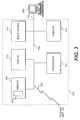
- FIG. 3is a block diagram illustrating a control unit of an imaging device
- FIG. 4is an image illustrating two-dimensional circular artifacts projected from spherical calibration markers
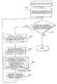
- FIG. 5is a flow chart of image processing methods consistent with the present invention for reducing the artifacts caused by calibration markers
- FIG. 6is an image of an expanded view of a calibration marker projection
- FIG. 7Ais an image illustrating two-dimensional circular artifacts projected from spherical calibration markers
- FIGS. 7B and 7Care versions of the image shown in FIG. 7A after application of methods consistent with the present invention.
- FIG. 8is an image of a calibration marker projection divided into four regions
- FIG. 9is a flow chart of image processing methods consistent with the present invention for eliminating artifacts caused by semi-transparent calibration markers.
- FIG. 10is a flow chart of image processing methods consistent with a second aspect of the present invention for eliminating artifacts caused by semi-transparent calibration markers.
- image processing operationsare used to improve images that include visual artifacts generated by calibration markers used in intrinsic calibration of the image.
- Artifacts introduced by opaque or semi-transparent calibration markersmay be completely or partially removed from the image.
- Methods consistent with the present inventionmay be implemented on images taken with an x-ray imaging device in which intrinsic image calibration is implemented.
- One such imaging deviceis the “Series9600 Mobile Digital Imaging System,” from OEC Medical Systems, Inc., of Salt Lake City, Utah.
- the “Series9600 Mobile Digital Imaging System”is structurally similar to imaging system 100 .
- methods consistent with the present inventionmay be implemented on images at a computer system not associated with the imaging device.
- FIG. 3is a block diagram illustrating control unit 120 in more detail. Communications between base unit 102 and control unit 120 are performed via transmission medium 302 , which may be, for example, a radio or cable link. Digital images may be received from base unit 102 and commands transmitted to base unit 102 . Control unit 120 may include an additional external connection, such as network connection 315 . Through network connection 315 , data, such as images stored in memory 304 , may be transmitted to additional computing resources, such as computer 305 .
- additional computing resourcessuch as computer 305 .
- Control unit 120further comprises a computer processor 303 and a memory 304 coupled to processor 303 through a bus 306 .
- Processor 303fetches computer instructions from memory 304 and executes those instructions.
- Processor 303also (1) reads data from and writes data to memory 304 , (2) sends data and control signals through bus 306 to one or more peripheral output devices 312 and 313 ; and (3) receives data and control signals through bus 306 from input device(s) 314 .
- Memory 304can include any type of computer memory, including, without limitation, random access memory (RAM), read-only memory (ROM), and storage devices that include storage media such as magnetic and/or optical disks.
- Memory 304includes a computer process 310 that processor 303 executes.
- a computer process in this descriptionis a collection of computer instructions and data that collectively define a task performed by control unit 120 .
- Input device 314is used by an operator to enter commands to control unit 120 .
- the commandsmay be executed directly by control unit 120 or transmitted to base unit 102 .
- Input device 314may be, for example, a keyboard, a pointing device such as a mouse, or a combination thereof
- Output devices 3 12 and 313are preferably a display and a printer, respectively.
- Display 312is typically used to exhibit images taken by base unit 102 and printer 3 13 is used to create hard copies of the images.
- images stored in memory 304may be processed by processor 303 to perform various image processing operations.
- processor 303may perform intrinsic calibration on an image or generate the location of a three-dimensional point from a series of two-dimensional images. Consistent with the present invention, processing section 303 also removes artifacts caused by calibration markers used in the intrinsic calibration process.
- Computer 305instead of processing section 303 , may alternatively perform image processing operations consistent with the present invention.
- control unit 120is exemplary only. One of ordinary skill in the art will recognize that many modifications could be made to the described architecture and still achieve the described functionality.
- each calibration markeris a three-dimensional shape that appears in the image as a two-dimensional object, although calibration markers can also be constructed using thin films that are essentially two-dimensional in nature. Many possible shapes, such as spheres and cylindrical rods can be used to implement the calibration markers. Spheres appear in the two-dimensional image as circles and cylindrical rods appear as lines. Throughout this disclosure, spherical calibration markers are illustrated, although one of ordinary skill in the art will recognize that calibration markers of any shape could be used.
- a typical C-arm calibration targetcontains a large set of calibration markers (e.g., 25+) with the markers positioned over one or more depth planes.
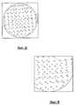
- FIG. 4is an image having two-dimensional circular artifacts projected from spherical calibration markers.
- Two different calibration marker patternswere used to generate image 400 .
- Large circles 402represent a first spherical pattern of the calibration markers and smaller circles 404 represent a second spherical pattern of the calibration markers.
- each spherical patternis rigidly fixed in a separate plane traversed by the x-rays.
- markers 402 and 404were opaque to the x-rays used to take the image, thus the two-dimensional projection of the markers appears as solid black circles.
- FIG. 5is a flow chart of image processing methods consistent with the present invention for reducing the artifacts caused by calibration markers, such as artifacts 402 and 404 of image 400 .
- the methods illustrated in FIG. 5may be performed after a received image has been intrinsically calibrated to reduce image distortion.
- processor 303For each digitized image that is to be processed, processor 303 begins by identifying the calibration marker projections in the image (step 502 ). As the shape, general pixel intensity, and relative position of the markers are known a priori, detection of the marker projections is a straightforward image processing operation well within the skill of one of ordinary skill in the art, and therefore will not be described further. Identification of the marker projections classifies the image pixels into those corresponding to the marker projections and those corresponding to anatomy or other non-marker objects.
- processor 303For each marker projection in the image, processor 303 identifies pixels surrounding the identified marker artifacts, (steps 503 and 504 ), and reads the values (intensities) of the surrounding pixels (step 506 ). Finally, the processor changes the pixel values of the marker projections to values based on that of the pixels surrounding the marker (step 508 ). The modified pixels of the marker projections tend to blend in more smoothly with the actual image, thereby reducing the visual distraction caused by the marker artifacts.
- processor 303may modify the marker pixels so that they are visible to the clinician but yet are still visibly less distracting than the original marker projections (optional step 509 ).
- this stepis achieved by supplementing the new marker projection values with a small constant offset (e.g., 5% of the maximum pixel value), thus causing the new marker projections to be visibly distinct but not visually distracting.
- FIG. 6is an image of an expanded view of one of calibration marker projections 404 .
- Small squares 601highlight pixels defined as surrounding pixels in step 504 .
- the “surrounding pixels”are not necessarily limited to just those pixels that immediately border marker projection 404 , but may include additional neighboring pixels.
- the surrounding pixelsmay include all the pixels with a certain radius of the outer border of the marker projection (e.g., a radius of five pixels) or all the non-marker pixels within a square aligned with the center of the marker projection.
- processor 303there are many possible approaches to appropriately modifying the pixel values within the marker projections as performed in step 508 .
- the best approach used by processor 303 in any particular situationmay vary depending on the circumstances, and may be selectable by the user or selected automatically by processor 303 . Exemplary ones of these approaches will now be discussed.
- processor 303simply calculates the average intensity value of surrounding pixels 601 (i.e., the sum of the surrounding pixel values divided by the number of surrounding pixels in the sample) and sets each of the pixels in marker projection 604 to that intensity value.
- FIG. 7Ais an image, similar to image 400 , having two-dimensional circular artifacts projected from spherical calibration markers.
- FIG. 7Bis an image after application of the averaging method applied to the image of FIG. 7 A.
- FIG. 7Cis the image shown in FIG. 7B after application of the averaging method and the addition of a small constant offset chosen to make the marker projection visibly distinct but not visibly distracting.
- processor 303divides marker projection 604 into multiple regions and separately calculate average intensity values of surrounding pixels for each region.
- An example of a marker projection divided into four regions (quadrants)is shown in FIG. 8 .
- Marker projection 804is surrounded by pixels 801 .
- Processor 303separately calculates the average value of the surround pixels in each of quadrants 810 - 813 and then sets the marker projection pixels in that quadrant to the calculated value.
- a second general class of approaches for determining underlying marker projection intensity valuesuses estimators that optimize a criterion function in order to derive the pixel intensities.
- This class of methodsinvolves maximum likelihood estimators such as the Expectation Maximization (EM) algorithm, neural networks, fuzzy systems, and other methods which estimate a set of parameters (i.e., the new marker projection intensity values) by maximizing a criterion function.
- EMExpectation Maximization
- neural networksi.e., the new marker projection intensity values
- fuzzy systemsi.e., the new marker projection intensity values
- an EM algorithmcould estimate underlying pixel intensities in a statistically optimal sense given the measured image and the current marker location. Any of these approaches may incorporate statistical models of the image that mathematically describe the expected image structure (e.g., measures of image texture or image variation, measures of feature orientation, etc.).
- artifacts introduced into an x-ray image by semi-transparent markersmay be substantially eliminated while preserving much of the true underlying image.
- the semi-transparent calibration markersshould be opaque enough so that they are visible enough to be automatically identified in the x-ray images, and transparent enough so that the features underlying the markers (i.e., the features along the x-ray projection path passing through the markers) will also influence the image intensity. When these conditions are satisfied, the marker projections may be completely eliminated while preserving the underlying image features by subtracting offset values from the detected marker projections.
- the semi-transparent calibration markersmay be made from a material such as a thin layer of copper (e.g., 0.5-2 mm thick) or a solid ceramic layer.
- FIG. 9is a flow chart of image processing methods consistent with the present invention for substantially eliminating artifacts caused by semi-transparent calibration markers.
- artifact eliminationis performed by subtracting a pre-measured offset from each pixel in the marker projections.
- the appropriate offset value to subtractis initially determined by processor 303 by acquiring an intensity image of a calibration marker projection in which no anatomy or other material is visible (step 901 ). That is, a preselected calibration marker is placed in an x-ray imaging path in which the x-rays pass only through the calibration marker. If all the pixels corresponding to the preselected calibration marker are of the same intensity, then the offset is simply that intensity value. If the intensity values of the pixels corresponding to the preselected calibration marker projection vary, whether by design or because of consistent variance in the calibration marker's material composition, then a separate offset value may be saved for each pixel.
- processor 303proceeds with eliminating the artifacts by identifying the calibration marker projections, (step 902 ), and, for each identified projection, (step 903 ), subtracting the acquired offset(s) from the pixels of the projection (step 904 ).
- steps 901 - 904will completely eliminate the artifacts from the image while leaving the true underlying image (e.g., the patient anatomy). Practically, image noise may prevent a perfect result.
- processor 303refines the result by applying an estimator function, such as the EM algorithm described above, to further improve the result (optional step 905 ).
- the input to the EM algorithmis the output of step 904 , while the output is a refined estimate of the true underlying pixel intensities.
- FIG. 10is a flow chart of image processing methods consistent with a second aspect of the present invention for substantially eliminating artifacts caused by semi-transparent calibration markers.
- the process illustrated in FIG. 10is similar to that illustrated in FIG. 9, except that instead of subtracting offset intensities from the pixels of the marker projections, an estimator optimizing a criterion function, such as the EM function, is used to modify the marker projections. More specifically, processor 303 eliminates, or substantially eliminates, the artifacts by identifying the calibration marker projections, (step 1002 ), and, for each identified projection, (step 1003 ), applies the estimator function (step 1005 ).
- artifacts present in x-ray imagesare de-emphasized. More particularly, artifacts may either be reduced in prominence (artifact reduction) or eliminated all together (artifact elimination), thereby improving the image presented to the clinician.
Landscapes
- Health & Medical Sciences (AREA)
- Life Sciences & Earth Sciences (AREA)
- Engineering & Computer Science (AREA)
- Medical Informatics (AREA)
- Heart & Thoracic Surgery (AREA)
- Molecular Biology (AREA)
- Biophysics (AREA)
- Nuclear Medicine, Radiotherapy & Molecular Imaging (AREA)
- Optics & Photonics (AREA)
- Pathology (AREA)
- Radiology & Medical Imaging (AREA)
- Biomedical Technology (AREA)
- Physics & Mathematics (AREA)
- High Energy & Nuclear Physics (AREA)
- Surgery (AREA)
- Animal Behavior & Ethology (AREA)
- General Health & Medical Sciences (AREA)
- Public Health (AREA)
- Veterinary Medicine (AREA)
- Computer Vision & Pattern Recognition (AREA)
- Apparatus For Radiation Diagnosis (AREA)
- Image Processing (AREA)
- Image Analysis (AREA)
- Analysing Materials By The Use Of Radiation (AREA)
Abstract
Description
This is a continuation of application Ser. No. 09/106,109, filed Jun. 29, 1998 now U.S. Pat. No. 6,118,845, which is incorporated herein by reference.
This invention relates generally to x-ray imaging systems, and more specifically, to the calibration of x-ray imaging systems.
Modem diagnostic medicine has benefitted significantly from radiology, which is the use of radiation, such as x-rays, to generate images of internal body structures. In general, to create an x-ray image, x-ray beams are passed through the body and absorbed, in varying amounts, by tissues in the body. An x-ray image is created based on the relative differences in the transmitted x-ray intensities.
FIG. 1A is a diagram illustrating a fluoroscopic C-arm x-ray imaging device.Imaging device 100 includes C-arm 103 attached tomobile base 102.X-ray source 105 is located at one end of C-arm 103 andx-ray receiving section 106 is located at the other end of C-arm 103. Receivingsection 106 generates an image representing the intensities of received x-rays. Typically, receivingsection 106 comprises an image intensifier that converts the x-rays to visible light and a charge coupled device (CCD) video camera that converts the visible light to digital images.
Images taken at themobile base 102 are transmitted tocontrol unit 120 for analysis. In particular,control unit 120 typically provides facilities for displaying, saving, digitally manipulating, or printing a hard copy of the received images.Control unit 120 additionally includes controls for controllingbase unit 102.
In operation, the patient is positioned inarea 110, between thex-ray source 105 and thex-ray receiving section 106. In response to an operator's command input atcontrol unit 120, x-rays emanating fromsource 105 pass throughpatient area 110 and into receivingsection 106, which generates a two-dimensional image of the patient.
Although each individual image taken bybase unit 102 is a two-dimensional image, techniques are known in the art through which multiple two-dimensional images taken from multiple perspectives can be used to infer the three-dimensional location of an anatomical projection. To change image perspective, C-arm 103 rotates as shown, for example, in FIG.1B. By taking multiple two-dimensional images ofpoint 124, but from different perspectives, the three-dimensional position ofpoint 124 may be determined.
Raw images generated by receivingsection 106 tend to suffer from undesirable distortion caused by a number of factors, including inherent image distortion in the image intensifier and external electromagnetic fields. An example of a true and a distorted image is shown in FIG.2. Checkerboard202 represents the true image of a checkerboard shaped object placed inimage taking area 110. The image taken by receivingsection 106, however, suffers significant distortion, as illustrated bydistorted image 204.
Intrinsic calibration, which is the process of correcting image distortion in a received image and learning the projective geometry of the imager, involves placing “calibration markers” in the path of the x-ray, where a calibration marker is an object opaque to x-rays. The calibration markers are rigidly arranged in predetermined patterns in one or more planes in the path of the x-rays and are visible in the recorded images.
Because the true relative position of the calibration markers in the recorded images is known,control unit 120 is able to calculate an amount of distortion at each pixel in the image (where a pixel is a single point in the image). Accordingly,control unit 120 can digitally compensate for the distortion in the image and generate a distortion-free, or at least a distortion improved image. A more detailed explanation of a method for performing intrinsic calibration is described in U.S. Pat. No. 5,442,674 to Picard et al, the contents of which are incorporated by reference herein.
A notable disadvantage in the conventional method of compensating for image distortion, as described above, is that although there is significantly less distortion in the image, projections of the calibration markers are present in the image. This is undesirable, as the projections of the markers may occlude important portions of the patient's anatomy and/or act as a visual distraction that prevents the clinician from concentrating on important features of the image.
There is, therefore, a need in the art to improve the intrinsic calibration process.
Objects and advantages of the invention will be set forth in part in the description which follows, and in part will be obvious from the description, or may be learned by practice of the invention. The objects and advantages of the invention will be realized and attained by means of the elements and combinations particularly pointed out in the appended claims.
To achieve the objects and in accordance with the purpose of the invention, as embodied and broadly described herein, a first aspect consistent with the present invention includes a method for causing a computer processor to perform the steps of: storing a digital image representing anatomy of a patient, the digital image including representations of calibration markers that at least partially occlude portions of the patient anatomy; and performing image processing operations on the digital image to de-emphasize the representations of the calibration markers.
Additional aspects of the present invention, related to the first aspect, are directed to a computer readable medium and a computer system.
A second aspect of the present invention is directed to a medical imaging system comprising a combination of elements, including: an x-ray source for generating x-rays; semi-transparent calibration markers positioned in a path of the x-rays; and an x-ray receiving device for receiving the generated x-rays and deriving a digital image representing objects through which the generated x-rays have passed, the digital image including representations of the calibration markers. A processor is coupled to the x-ray receiving device and performs image processing operations on the digital image, the digital processing operations removing distortion from the image by performing intrinsic calibration on the image based on projections of the semi-transparent calibration markers in the image.
A third aspect of the present invention is directed to a method of creating an image of an object. The method comprises the steps of: transmitting x-rays in a path including a target object and calibration markers arranged in a predetermined pattern; receiving the transmitted x-rays; deriving a digital image representing the object and the calibration markers; and de-emphasizing the representations of the calibration markers in the digital image.
Additional aspects of the present invention, related to the third aspect, are directed to a computer readable medium and a computer system.
The accompanying drawings, which are incorporated in and constitute a part of this specification, illustrate several embodiments consistent with this invention and, together with the description, help explain the principles of the invention. In the drawings,
FIGS. 1A and 1B are diagrams illustrating a fluoroscopic C-arm x-ray imaging device;
FIG. 2 is a diagram illustrating a true and a distorted image taken with a fluoroscopic C-arm x-ray imaging device;
FIG. 3 is a block diagram illustrating a control unit of an imaging device;
FIG. 4 is an image illustrating two-dimensional circular artifacts projected from spherical calibration markers;
FIG. 5 is a flow chart of image processing methods consistent with the present invention for reducing the artifacts caused by calibration markers;
FIG. 6 is an image of an expanded view of a calibration marker projection;
FIG. 7A is an image illustrating two-dimensional circular artifacts projected from spherical calibration markers;
FIGS. 7B and 7C are versions of the image shown in FIG. 7A after application of methods consistent with the present invention;
FIG. 8 is an image of a calibration marker projection divided into four regions;
FIG. 9 is a flow chart of image processing methods consistent with the present invention for eliminating artifacts caused by semi-transparent calibration markers; and
FIG. 10 is a flow chart of image processing methods consistent with a second aspect of the present invention for eliminating artifacts caused by semi-transparent calibration markers.
As described herein, image processing operations are used to improve images that include visual artifacts generated by calibration markers used in intrinsic calibration of the image. Artifacts introduced by opaque or semi-transparent calibration markers may be completely or partially removed from the image.
Referring to the accompanying drawings, detailed description of embodiments consistent with the present invention will now be described.
Methods consistent with the present invention may be implemented on images taken with an x-ray imaging device in which intrinsic image calibration is implemented. One such imaging device is the “Series9600 Mobile Digital Imaging System,” from OEC Medical Systems, Inc., of Salt Lake City, Utah. The “Series9600 Mobile Digital Imaging System” is structurally similar toimaging system 100. Alternatively, methods consistent with the present invention may be implemented on images at a computer system not associated with the imaging device.
FIG. 3 is a block diagram illustratingcontrol unit 120 in more detail. Communications betweenbase unit 102 andcontrol unit 120 are performed viatransmission medium 302, which may be, for example, a radio or cable link. Digital images may be received frombase unit 102 and commands transmitted tobase unit 102.Control unit 120 may include an additional external connection, such asnetwork connection 315. Throughnetwork connection 315, data, such as images stored inmemory 304, may be transmitted to additional computing resources, such ascomputer 305.
In operation, images stored inmemory 304 may be processed byprocessor 303 to perform various image processing operations. For example,processor 303 may perform intrinsic calibration on an image or generate the location of a three-dimensional point from a series of two-dimensional images. Consistent with the present invention, processingsection 303 also removes artifacts caused by calibration markers used in the intrinsic calibration process.Computer 305, instead of processingsection 303, may alternatively perform image processing operations consistent with the present invention.
The above-described architecture ofcontrol unit 120 is exemplary only. One of ordinary skill in the art will recognize that many modifications could be made to the described architecture and still achieve the described functionality.
As previously discussed, intrinsic calibration uses calibration markers placed at fixed, predetermined positions in the x-ray imaging path to either obtain an image transformation that removes distortion from the original image generated by receivingsection 106 or to learn the projective geometry of the imager (i.e., to discern how a pixel in the image projects into three-dimensional space). Typically, each calibration marker is a three-dimensional shape that appears in the image as a two-dimensional object, although calibration markers can also be constructed using thin films that are essentially two-dimensional in nature. Many possible shapes, such as spheres and cylindrical rods can be used to implement the calibration markers. Spheres appear in the two-dimensional image as circles and cylindrical rods appear as lines. Throughout this disclosure, spherical calibration markers are illustrated, although one of ordinary skill in the art will recognize that calibration markers of any shape could be used.
A typical C-arm calibration target contains a large set of calibration markers (e.g., 25+) with the markers positioned over one or more depth planes.
Consistent with a first aspect of the present invention, artifacts introduced into an x-ray image by radio-opaque markers are reduced.
FIG. 4 is an image having two-dimensional circular artifacts projected from spherical calibration markers. Two different calibration marker patterns were used to generateimage 400.Large circles 402 represent a first spherical pattern of the calibration markers andsmaller circles 404 represent a second spherical pattern of the calibration markers. Preferably, each spherical pattern is rigidly fixed in a separate plane traversed by the x-rays. As shown,markers
FIG. 5 is a flow chart of image processing methods consistent with the present invention for reducing the artifacts caused by calibration markers, such asartifacts image 400. The methods illustrated in FIG. 5 may be performed after a received image has been intrinsically calibrated to reduce image distortion.
For each digitized image that is to be processed,processor 303 begins by identifying the calibration marker projections in the image (step502). As the shape, general pixel intensity, and relative position of the markers are known a priori, detection of the marker projections is a straightforward image processing operation well within the skill of one of ordinary skill in the art, and therefore will not be described further. Identification of the marker projections classifies the image pixels into those corresponding to the marker projections and those corresponding to anatomy or other non-marker objects.
For each marker projection in the image,processor 303 identifies pixels surrounding the identified marker artifacts, (steps 503 and504), and reads the values (intensities) of the surrounding pixels (step506). Finally, the processor changes the pixel values of the marker projections to values based on that of the pixels surrounding the marker (step508). The modified pixels of the marker projections tend to blend in more smoothly with the actual image, thereby reducing the visual distraction caused by the marker artifacts.
Because the new marker projection values are only estimates of the intensities of the true underlying image data, it is possible that the new marker projection values will not accurately reflect the true image and will mislead the clinician. Accordingly,processor 303 may modify the marker pixels so that they are visible to the clinician but yet are still visibly less distracting than the original marker projections (optional step509). Preferably, this step is achieved by supplementing the new marker projection values with a small constant offset (e.g., 5% of the maximum pixel value), thus causing the new marker projections to be visibly distinct but not visually distracting.
FIG. 6 is an image of an expanded view of one ofcalibration marker projections 404.Small squares 601 highlight pixels defined as surrounding pixels instep 504. As shown, the “surrounding pixels” are not necessarily limited to just those pixels that immediately bordermarker projection 404, but may include additional neighboring pixels. For example, the surrounding pixels may include all the pixels with a certain radius of the outer border of the marker projection (e.g., a radius of five pixels) or all the non-marker pixels within a square aligned with the center of the marker projection.
There are many possible approaches to appropriately modifying the pixel values within the marker projections as performed instep 508. The best approach used byprocessor 303 in any particular situation may vary depending on the circumstances, and may be selectable by the user or selected automatically byprocessor 303. Exemplary ones of these approaches will now be discussed.
In a first method,processor 303 simply calculates the average intensity value of surrounding pixels601 (i.e., the sum of the surrounding pixel values divided by the number of surrounding pixels in the sample) and sets each of the pixels in marker projection604 to that intensity value. FIG. 7A is an image, similar toimage 400, having two-dimensional circular artifacts projected from spherical calibration markers. FIG. 7B is an image after application of the averaging method applied to the image of FIG.7A. FIG. 7C is the image shown in FIG. 7B after application of the averaging method and the addition of a small constant offset chosen to make the marker projection visibly distinct but not visibly distracting.
In a second method,processor 303 divides marker projection604 into multiple regions and separately calculate average intensity values of surrounding pixels for each region. An example of a marker projection divided into four regions (quadrants) is shown in FIG.8.Marker projection 804 is surrounded bypixels 801.Processor 303 separately calculates the average value of the surround pixels in each of quadrants810-813 and then sets the marker projection pixels in that quadrant to the calculated value.
Other methods, in addition to the average and multiple region averaging methods discussed above, may also be used to calculate new marker projection pixel values. In particular, a second general class of approaches for determining underlying marker projection intensity values uses estimators that optimize a criterion function in order to derive the pixel intensities. This class of methods involves maximum likelihood estimators such as the Expectation Maximization (EM) algorithm, neural networks, fuzzy systems, and other methods which estimate a set of parameters (i.e., the new marker projection intensity values) by maximizing a criterion function. For example, an EM algorithm could estimate underlying pixel intensities in a statistically optimal sense given the measured image and the current marker location. Any of these approaches may incorporate statistical models of the image that mathematically describe the expected image structure (e.g., measures of image texture or image variation, measures of feature orientation, etc.).
Consistent with a second aspect of the present invention, artifacts introduced into an x-ray image by semi-transparent markers may be substantially eliminated while preserving much of the true underlying image.
The semi-transparent calibration markers should be opaque enough so that they are visible enough to be automatically identified in the x-ray images, and transparent enough so that the features underlying the markers (i.e., the features along the x-ray projection path passing through the markers) will also influence the image intensity. When these conditions are satisfied, the marker projections may be completely eliminated while preserving the underlying image features by subtracting offset values from the detected marker projections.
The semi-transparent calibration markers may be made from a material such as a thin layer of copper (e.g., 0.5-2 mm thick) or a solid ceramic layer.
FIG. 9 is a flow chart of image processing methods consistent with the present invention for substantially eliminating artifacts caused by semi-transparent calibration markers.
Essentially, artifact elimination is performed by subtracting a pre-measured offset from each pixel in the marker projections. The appropriate offset value to subtract is initially determined byprocessor 303 by acquiring an intensity image of a calibration marker projection in which no anatomy or other material is visible (step901). That is, a preselected calibration marker is placed in an x-ray imaging path in which the x-rays pass only through the calibration marker. If all the pixels corresponding to the preselected calibration marker are of the same intensity, then the offset is simply that intensity value. If the intensity values of the pixels corresponding to the preselected calibration marker projection vary, whether by design or because of consistent variance in the calibration marker's material composition, then a separate offset value may be saved for each pixel.
Once the offset for a particular image has been determined,processor 303 proceeds with eliminating the artifacts by identifying the calibration marker projections, (step902), and, for each identified projection, (step903), subtracting the acquired offset(s) from the pixels of the projection (step904). Ideally, steps901-904 will completely eliminate the artifacts from the image while leaving the true underlying image (e.g., the patient anatomy). Practically, image noise may prevent a perfect result. In these situations,processor 303 refines the result by applying an estimator function, such as the EM algorithm described above, to further improve the result (optional step905). The input to the EM algorithm is the output ofstep 904, while the output is a refined estimate of the true underlying pixel intensities.
FIG. 10 is a flow chart of image processing methods consistent with a second aspect of the present invention for substantially eliminating artifacts caused by semi-transparent calibration markers. The process illustrated in FIG. 10 is similar to that illustrated in FIG. 9, except that instead of subtracting offset intensities from the pixels of the marker projections, an estimator optimizing a criterion function, such as the EM function, is used to modify the marker projections. More specifically,processor 303 eliminates, or substantially eliminates, the artifacts by identifying the calibration marker projections, (step1002), and, for each identified projection, (step1003), applies the estimator function (step1005).
As described in this disclosure, artifacts present in x-ray images are de-emphasized. More particularly, artifacts may either be reduced in prominence (artifact reduction) or eliminated all together (artifact elimination), thereby improving the image presented to the clinician.
While there has been illustrated and, described what are at present considered to be preferred embodiments and methods of the present invention, it will be understood by those skilled in the art that various changes and modifications may be made, and equivalents may be substituted for elements thereof without departing from the true scope of the invention. For example, although described in the context of a medical imaging system using x-rays, methods consistent with the present invention can be performed on any digitized input image.
In addition, many modifications may be made to adapt a particular element, technique or implementation to the teachings of the present invention without departing from the central scope of the invention. Therefore, it is intended that this invention not be limited to the particular embodiments and methods disclosed herein, but that the invention include all embodiments falling within the scope of the appended claims.
Claims (48)
1. A medical imaging system comprising:
an x-ray source for generating x-rays;
calibration markers positioned in a path of the x-rays;
an x-ray receiving device for receiving the generated x-rays and deriving a digital image representing objects through which the generated x-rays have passed, the digital image including representations of the calibration markers; and
a processor coupled to the x-ray receiving device for performing image processing operations on the digital image, the image processing operations modifying the visual presence of the representations of the calibration markers, based on characteristics of an image area surrounding the calibration markers.
2. The system ofclaim 1 , wherein the x-ray receiving device further comprises an image intensifier and a charge coupled device (CCD) array for deriving the digital image from the x-rays.
3. The system ofclaim 1 , wherein the processor modifies the visual presence of the representations of the calibration markers using a maximum likelihood estimator that maximizes a criterion function.
4. The system ofclaim 3 , wherein the maximum likelihood estimator is an Expectation Maximizing algorithm.
5. The system ofclaim 1 , wherein the x-ray receiving device provides a representation of calibration markers that are opaque or semi-transparent to the x-rays.
6. The system ofclaim 5 , wherein the processor further includes means for identifying pixels in the digital image that surround the calibration markers and means for modifying the representations of the calibration markers based on the values of the pixels that surround the representations of the calibration markers.
7. The system ofclaim 6 , wherein modifying the representation of the calibration markers further includes using an average value of the pixels that surround the representations of the calibration markers.
8. The system ofclaim 6 , wherein modifying the representations of the calibration markers further includes separately calculating average intensity values for separate regions of the digital image surrounding the representation of the calibration markers.
9. The system ofclaim 6 , wherein the modifying means includes an estimator using the value of the pixels surrounding the representation of the calibration markers.
10. The system ofclaim 6 , wherein identifying the representations of the calibration markers further includes identifying the calibration markers by classifying a plurality of image pixels into image pixels corresponding to the calibration markers and image pixels corresponding to anatomy or other objects.
11. The system ofclaim 6 , wherein identifying the pixels in the digital image includes identifying pixels that are not directly adjacent to the calibration markers.
12. The system ofclaim 6 , wherein the processor further includes means for adding a constant offset to the modified representations of the calibration markers to enhance the visibility of the representations.
13. The system ofclaim 6 , wherein modifying the representations of the calibration markers further includes adding an offset to the representations of the calibration markers that have been modified to enhance the visibility of the representations.
14. The system ofclaim 13 , wherein the processor further includes means for acquiring an offset value corresponding to an intensity of one of the calibration marker representations in which the x-rays have not traversed the objects.
15. The system ofclaim 14 , wherein the processor further includes means for subtracting the offset value from each of the calibration marker representations.
16. The system ofclaim 15 , wherein the processor further includes means for refining the subtracted versions of the calibration marker representations by using an estimator algorithm that optimizes a criterion function.
17. A method of creating an image of a target comprising:
transmitting x-rays at the target and calibration markers;
collecting the x-rays;
producing a digital image representing the target and calibration markers; and
processing the digital image to modify the representation of the calibration markers, based on characteristics of an image area surrounding the calibration markers.
18. The method ofclaim 17 , wherein the identifying of the representations of the calibration markers includes identifying the calibration markers by classifying a plurality of image pixels into image pixels corresponding to the calibration markers and image pixels corresponding to anatomy or other objects.
19. The method ofclaim 17 , wherein the transmitting further includes transmitting the x-rays through semi-transparent calibration markers arranged in a predetermined pattern.
20. The method ofclaim 19 , wherein processing includes eliminating the representations of the calibration markers by subtracting an offset from pixels in the digital image that comprise the calibration marker representations.
21. The method ofclaim 17 , wherein the transmitting further includes transmitting the x-rays at calibration markers that are opaque or semi-transparent to the x-rays.
22. The method ofclaim 21 , wherein the processing includes identifying pixels in the digital image that surround the calibration markers and modifying the representations of the calibration markers based on the values of the pixels that surround the representations of the calibration markers.
23. The method ofclaim 22 , wherein the identifying further includes identifying pixels that are not directly adjacent to the calibration markers.
24. The method ofclaim 22 , wherein the modifying of the representation of the calibration markers further includes using an average value of the pixels that surround the representation of the calibration markers.
25. The method ofclaim 22 , further comprising adding an offset to the modified representations of the calibration markers to enhance the visibility of the representations.
26. The method ofclaim 22 , wherein modifying of the representation of the calibration markers includes separately calculating average intensity values for separate regions of the digital image surrounding the representation of the calibration markers.
27. The method ofclaim 22 , wherein the modifying of the representation of the calibration markers further includes using an estimator utilizing the value of the pixels surrounding the representation of the calibration markers.
28. A computer readable medium containing computer instructions for causing a processor to perform processing comprising:
storing a digital image representing anatomy of a patient, the digital image including representations of calibration markers that at least partially occlude portions of the patient anatomy; and
performing image processing operations on the digital image to modify the representations of the calibration markers, based on characteristics of an image area surrounding the calibration markers.
29. The computer readable medium ofclaim 28 , wherein the instructions further include instructions for eliminating the representations of the calibration markers by subtracting an offset from pixels in the digital image that comprise the calibration marker representations.
30. The computer readable medium ofclaim 28 , wherein the instructions further include instructions for modifying the visual presence of the representations of the calibration markers using a maximum likelihood estimator that maximizes a criterion function.
31. The computer readable medium ofclaim 30 wherein the maximum likelihood estimator is an Expectation Maximizing algorithm.
32. The computer readable medium ofclaim 28 , wherein the instructions further include instructions for identifying pixels in the digital image that surround the calibration markers and modifying the representations of the calibration markers based on the values of the pixels that surround the representations of the calibration markers.
33. The computer readable medium ofclaim 32 , wherein the instructions further include instructions for identifying pixels in the digital image that are not directly adjacent to the calibration markers.
34. The computer readable medium ofclaim 32 , wherein the instructions for modifying further include using an average value of the pixels that surround the representation of the calibration markers.
35. The computer readable medium ofclaim 32 , wherein the instructions further include separately calculating average intensity values for separate regions of the digital image surrounding the representation of the calibration markers.
36. The computer readable medium ofclaim 32 , wherein the instructions further include using an estimator to calculate the value of the pixels surrounding the representation of the calibration markers.
37. The computer readable medium ofclaim 32 , wherein the instructions include identifying the calibration markers by classifying a plurality of image pixels into image pixels corresponding to the calibration markers and image pixels corresponding to anatomy or other objects.
38. The computer readable medium ofclaim 32 , further including instructions for adding an offset to the modified representations of the calibration markers to enhance the visibility of the representations.
39. A computer system comprising:
a first computer memory storing a digital image representing anatomy of a patient, the digital image including representations of calibration markers that at least partially occlude portions of the patient anatomy;
a second memory storing instruction for performing image processing operations on the digital image to modify the representations of the calibration markers based on characteristics of an image area surrounding the calibration markers; and
a processor coupled to the first and second memory for executing the instructions stored in the second memory.
40. The computer system ofclaim 39 , wherein the processor modifies the visual presence of the representations of the calibration markers using a maximum likelihood estimator that maximizes a criterion function.
41. The computer system ofclaim 40 , wherein the maximum likelihood estimator is an Expectation Maximizing algorithm.
42. The computer system ofclaim 39 , wherein the processor further includes means for identifying pixels in the digital image that surround the calibration markers and means for modifying the representations of the calibration markers based on the values of the pixels that surround the representations of the calibration markers.
43. The computer system ofclaim 42 , wherein the processor further includes means for adding a constant offset to the modified representations of the calibration markers to enhance the visibility of the representations.
44. The computer system ofclaim 42 , wherein the processor further includes means for modifying the representations of the calibration markers by identifying pixels in the digital image that are not directly adjacent to the calibration markers.
45. The computer system ofclaim 42 , wherein the processor further includes means for modifying the representations of the calibration markers by using an average value of the pixels that surround the representation of the calibration markers.
46. The computer system ofclaim 42 , wherein the processor further includes means for modifying the representations of the calibration markers by separately calculating average intensity values for separate regions of the digital image surrounding the representation of the calibration markers.
47. The computer system ofclaim 42 , wherein the processor further includes means for modifying the representations of the calibration markers using an estimator utilizing the value of the pixels surrounding the representation of the calibration markers.
48. The computer system ofclaim 42 , wherein the processor further includes means for modifying the representations of the calibration markers by classifying a plurality of image pixels into image pixels corresponding to the calibration markers and image pixels corresponding to anatomy or other objects.
Priority Applications (2)
| Application Number | Priority Date | Filing Date | Title |
|---|---|---|---|
| US09/591,512US6370224B1 (en) | 1998-06-29 | 2000-06-12 | System and methods for the reduction and elimination of image artifacts in the calibration of x-ray imagers |
| US10/016,487US6510198B2 (en) | 1998-06-29 | 2001-12-10 | System and methods for the reduction and elimination of image artifacts in the calibration of x-ray imagers |
Applications Claiming Priority (2)
| Application Number | Priority Date | Filing Date | Title |
|---|---|---|---|
| US09/106,109US6118845A (en) | 1998-06-29 | 1998-06-29 | System and methods for the reduction and elimination of image artifacts in the calibration of X-ray imagers |
| US09/591,512US6370224B1 (en) | 1998-06-29 | 2000-06-12 | System and methods for the reduction and elimination of image artifacts in the calibration of x-ray imagers |
Related Parent Applications (1)
| Application Number | Title | Priority Date | Filing Date |
|---|---|---|---|
| US09/106,109ContinuationUS6118845A (en) | 1998-06-29 | 1998-06-29 | System and methods for the reduction and elimination of image artifacts in the calibration of X-ray imagers |
Related Child Applications (1)
| Application Number | Title | Priority Date | Filing Date |
|---|---|---|---|
| US10/016,487ContinuationUS6510198B2 (en) | 1998-06-29 | 2001-12-10 | System and methods for the reduction and elimination of image artifacts in the calibration of x-ray imagers |
Publications (1)
| Publication Number | Publication Date |
|---|---|
| US6370224B1true US6370224B1 (en) | 2002-04-09 |
Family
ID=22309543
Family Applications (3)
| Application Number | Title | Priority Date | Filing Date |
|---|---|---|---|
| US09/106,109Expired - LifetimeUS6118845A (en) | 1998-06-29 | 1998-06-29 | System and methods for the reduction and elimination of image artifacts in the calibration of X-ray imagers |
| US09/591,512Expired - LifetimeUS6370224B1 (en) | 1998-06-29 | 2000-06-12 | System and methods for the reduction and elimination of image artifacts in the calibration of x-ray imagers |
| US10/016,487Expired - LifetimeUS6510198B2 (en) | 1998-06-29 | 2001-12-10 | System and methods for the reduction and elimination of image artifacts in the calibration of x-ray imagers |
Family Applications Before (1)
| Application Number | Title | Priority Date | Filing Date |
|---|---|---|---|
| US09/106,109Expired - LifetimeUS6118845A (en) | 1998-06-29 | 1998-06-29 | System and methods for the reduction and elimination of image artifacts in the calibration of X-ray imagers |
Family Applications After (1)
| Application Number | Title | Priority Date | Filing Date |
|---|---|---|---|
| US10/016,487Expired - LifetimeUS6510198B2 (en) | 1998-06-29 | 2001-12-10 | System and methods for the reduction and elimination of image artifacts in the calibration of x-ray imagers |
Country Status (6)
| Country | Link |
|---|---|
| US (3) | US6118845A (en) |
| EP (2) | EP2025289B1 (en) |
| AT (2) | ATE522176T1 (en) |
| AU (1) | AU4837799A (en) |
| DE (1) | DE69939778D1 (en) |
| WO (1) | WO2000000086A1 (en) |
Cited By (28)
| Publication number | Priority date | Publication date | Assignee | Title |
|---|---|---|---|---|
| US6510198B2 (en)* | 1998-06-29 | 2003-01-21 | Surgical Navigation Technologies, Inc. | System and methods for the reduction and elimination of image artifacts in the calibration of x-ray imagers |
| FR2841118A1 (en) | 2002-06-20 | 2003-12-26 | Perception Raisonnement Action | DETERMINING THE POSITION OF A RADIOGRAPHY OR RADIOSCOPY DEVICE |
| US6801646B1 (en)* | 2001-07-19 | 2004-10-05 | Virtualscopics, Llc | System and method for reducing or eliminating streak artifacts and illumination inhomogeneity in CT imaging |
| US20050123100A1 (en)* | 2003-12-05 | 2005-06-09 | Jiang Hsieh | Method and system for target angle heel effect compensation |
| US20050178584A1 (en)* | 2002-01-22 | 2005-08-18 | Xingwu Wang | Coated stent and MR imaging thereof |
| US20070078678A1 (en)* | 2005-09-30 | 2007-04-05 | Disilvestro Mark R | System and method for performing a computer assisted orthopaedic surgical procedure |
| US20070161888A1 (en)* | 2005-12-30 | 2007-07-12 | Sherman Jason T | System and method for registering a bone of a patient with a computer assisted orthopaedic surgery system |
| US20070163367A1 (en)* | 2005-12-30 | 2007-07-19 | Sherman Jason T | Magnetic sensor array |
| US20070167741A1 (en)* | 2005-12-30 | 2007-07-19 | Sherman Jason T | Apparatus and method for registering a bone of a patient with a computer assisted orthopaedic surgery system |
| US20070167703A1 (en)* | 2005-12-30 | 2007-07-19 | Sherman Jason T | Method for determining a position of a magnetic source |
| US20070253540A1 (en)* | 2006-04-27 | 2007-11-01 | General Electric Company | Methods and apparatus for mobile imaging systems |
| US20080112537A1 (en)* | 2006-11-14 | 2008-05-15 | Jason Stuart Katcha | Power Handling Methods and Apparatus |
| US20080154127A1 (en)* | 2006-12-21 | 2008-06-26 | Disilvestro Mark R | Method and system for registering a bone of a patient with a computer assisted orthopaedic surgery system |
| US7953471B2 (en) | 2004-05-03 | 2011-05-31 | Medtronic Navigation, Inc. | Method and apparatus for implantation between two vertebral bodies |
| US8265949B2 (en) | 2007-09-27 | 2012-09-11 | Depuy Products, Inc. | Customized patient surgical plan |
| US8343159B2 (en) | 2007-09-30 | 2013-01-01 | Depuy Products, Inc. | Orthopaedic bone saw and method of use thereof |
| US8768437B2 (en) | 1998-08-20 | 2014-07-01 | Sofamor Danek Holdings, Inc. | Fluoroscopic image guided surgery system with intraoperative registration |
| EP2868277A1 (en) | 2013-11-04 | 2015-05-06 | Surgivisio | Method for reconstructing a 3D image from 2D X-ray images |
| USD757270S1 (en)* | 2011-08-30 | 2016-05-24 | Canon Kabushiki Kaisha | X-ray device for medical treatment |
| US9545233B2 (en) | 2012-05-22 | 2017-01-17 | Mazor Robotics Ltd. | On-site verification of implant positioning |
| US9950194B2 (en) | 2014-09-09 | 2018-04-24 | Mevion Medical Systems, Inc. | Patient positioning system |
| US20180220100A1 (en)* | 2017-01-30 | 2018-08-02 | Novartis Ag | Systems and method for augmented reality ophthalmic surgical microscope projection |
| US10058338B2 (en) | 2000-07-24 | 2018-08-28 | Mazor Robotics Ltd. | Miniature bone-attached surgical robot |
| US10893842B2 (en) | 2018-02-08 | 2021-01-19 | Covidien Lp | System and method for pose estimation of an imaging device and for determining the location of a medical device with respect to a target |
| US11055648B2 (en) | 2006-05-25 | 2021-07-06 | DePuy Synthes Products, Inc. | Method and system for managing inventories of orthopaedic implants |
| US11051829B2 (en) | 2018-06-26 | 2021-07-06 | DePuy Synthes Products, Inc. | Customized patient-specific orthopaedic surgical instrument |
| US12033324B2 (en) | 2019-06-06 | 2024-07-09 | The Research Foundation For The State University Of New York | System and method for identifying fractures in digitized x-rays |
| US12369981B2 (en) | 2023-02-07 | 2025-07-29 | Depuy Ireland Unlimited Company | Systems and methods for bone model registration with adaptive soft tissue thickness |
Families Citing this family (170)
| Publication number | Priority date | Publication date | Assignee | Title |
|---|---|---|---|---|
| FR2652928B1 (en) | 1989-10-05 | 1994-07-29 | Diadix Sa | INTERACTIVE LOCAL INTERVENTION SYSTEM WITHIN A AREA OF A NON-HOMOGENEOUS STRUCTURE. |
| AU675077B2 (en) | 1992-08-14 | 1997-01-23 | British Telecommunications Public Limited Company | Position location system |
| US5592939A (en) | 1995-06-14 | 1997-01-14 | Martinelli; Michael A. | Method and system for navigating a catheter probe |
| US6282261B1 (en)* | 1996-02-21 | 2001-08-28 | Lunar Corporation | Multi-mode x-ray image intensifier system |
| US6226548B1 (en) | 1997-09-24 | 2001-05-01 | Surgical Navigation Technologies, Inc. | Percutaneous registration apparatus and method for use in computer-assisted surgical navigation |
| US6021343A (en) | 1997-11-20 | 2000-02-01 | Surgical Navigation Technologies | Image guided awl/tap/screwdriver |
| US6348058B1 (en) | 1997-12-12 | 2002-02-19 | Surgical Navigation Technologies, Inc. | Image guided spinal surgery guide, system, and method for use thereof |
| US6289235B1 (en)* | 1998-03-05 | 2001-09-11 | Wake Forest University | Method and system for creating three-dimensional images using tomosynthetic computed tomography |
| US6081577A (en)* | 1998-07-24 | 2000-06-27 | Wake Forest University | Method and system for creating task-dependent three-dimensional images |
| US6470207B1 (en) | 1999-03-23 | 2002-10-22 | Surgical Navigation Technologies, Inc. | Navigational guidance via computer-assisted fluoroscopic imaging |
| US6491699B1 (en) | 1999-04-20 | 2002-12-10 | Surgical Navigation Technologies, Inc. | Instrument guidance method and system for image guided surgery |
| US7803765B2 (en)* | 1999-05-05 | 2010-09-28 | Phylogica Limited | Methods of constructing biodiverse gene fragment libraries and biological modulators isolated therefrom |
| US6738531B1 (en)* | 1999-05-10 | 2004-05-18 | Fuji Photo Film Co., Ltd. | Image processing method and apparatus |
| US6260999B1 (en)* | 1999-07-26 | 2001-07-17 | Siemens Medical Systems, Inc. | Isocenter localization using electronic portal imaging |
| US6533454B1 (en)* | 1999-09-30 | 2003-03-18 | Bionx Implants Oy | Surgical system for tissue fixation |
| US6447163B1 (en)* | 1999-09-30 | 2002-09-10 | Siemens Corporate Research, Inc. | Method for aligning and superimposing X-ray and video images |
| US6499488B1 (en) | 1999-10-28 | 2002-12-31 | Winchester Development Associates | Surgical sensor |
| US11331150B2 (en) | 1999-10-28 | 2022-05-17 | Medtronic Navigation, Inc. | Method and apparatus for surgical navigation |
| US6493573B1 (en) | 1999-10-28 | 2002-12-10 | Winchester Development Associates | Method and system for navigating a catheter probe in the presence of field-influencing objects |
| US7366562B2 (en) | 2003-10-17 | 2008-04-29 | Medtronic Navigation, Inc. | Method and apparatus for surgical navigation |
| US6381485B1 (en) | 1999-10-28 | 2002-04-30 | Surgical Navigation Technologies, Inc. | Registration of human anatomy integrated for electromagnetic localization |
| US8644907B2 (en) | 1999-10-28 | 2014-02-04 | Medtronic Navigaton, Inc. | Method and apparatus for surgical navigation |
| US6474341B1 (en) | 1999-10-28 | 2002-11-05 | Surgical Navigation Technologies, Inc. | Surgical communication and power system |
| US8239001B2 (en) | 2003-10-17 | 2012-08-07 | Medtronic Navigation, Inc. | Method and apparatus for surgical navigation |
| US6379302B1 (en) | 1999-10-28 | 2002-04-30 | Surgical Navigation Technologies Inc. | Navigation information overlay onto ultrasound imagery |
| US7635390B1 (en) | 2000-01-14 | 2009-12-22 | Marctec, Llc | Joint replacement component having a modular articulating surface |
| US6702821B2 (en) | 2000-01-14 | 2004-03-09 | The Bonutti 2003 Trust A | Instrumentation for minimally invasive joint replacement and methods for using same |
| US7104996B2 (en) | 2000-01-14 | 2006-09-12 | Marctec. Llc | Method of performing surgery |
| US6725080B2 (en) | 2000-03-01 | 2004-04-20 | Surgical Navigation Technologies, Inc. | Multiple cannula image guided tool for image guided procedures |
| US6535756B1 (en) | 2000-04-07 | 2003-03-18 | Surgical Navigation Technologies, Inc. | Trajectory storage apparatus and method for surgical navigation system |
| US6856827B2 (en)* | 2000-04-28 | 2005-02-15 | Ge Medical Systems Global Technology Company, Llc | Fluoroscopic tracking and visualization system |
| US6484049B1 (en) | 2000-04-28 | 2002-11-19 | Ge Medical Systems Global Technology Company, Llc | Fluoroscopic tracking and visualization system |
| US6856826B2 (en)* | 2000-04-28 | 2005-02-15 | Ge Medical Systems Global Technology Company, Llc | Fluoroscopic tracking and visualization system |
| US7085400B1 (en) | 2000-06-14 | 2006-08-01 | Surgical Navigation Technologies, Inc. | System and method for image based sensor calibration |
| US6907281B2 (en)* | 2000-09-07 | 2005-06-14 | Ge Medical Systems | Fast mapping of volumetric density data onto a two-dimensional screen |
| US6636757B1 (en) | 2001-06-04 | 2003-10-21 | Surgical Navigation Technologies, Inc. | Method and apparatus for electromagnetic navigation of a surgical probe near a metal object |
| US7708741B1 (en) | 2001-08-28 | 2010-05-04 | Marctec, Llc | Method of preparing bones for knee replacement surgery |
| US6754522B2 (en) | 2001-09-05 | 2004-06-22 | Medimag C.V.I., Inc. | Imaging methods and apparatus particularly useful for two and three-dimensional angiography |
| JP4499422B2 (en)* | 2002-01-16 | 2010-07-07 | アイ−デント イメージング, インコーポレイテッド | Oral implant template |
| EP1346687B1 (en) | 2002-02-22 | 2007-03-21 | BrainLAB AG | Method for spacial calibration of X-ray imaging data and calibration device with reduced height |
| US6947786B2 (en) | 2002-02-28 | 2005-09-20 | Surgical Navigation Technologies, Inc. | Method and apparatus for perspective inversion |
| US6990368B2 (en) | 2002-04-04 | 2006-01-24 | Surgical Navigation Technologies, Inc. | Method and apparatus for virtual digital subtraction angiography |
| US7998062B2 (en) | 2004-03-29 | 2011-08-16 | Superdimension, Ltd. | Endoscope structures and techniques for navigating to a target in branched structure |
| EP1511421B1 (en)* | 2002-05-23 | 2012-09-19 | Ecole Nationale Supérieure D'Arts et Métiers ENSAM | Stereoradiography device and method for the use thereof |
| US7299805B2 (en) | 2002-06-07 | 2007-11-27 | Marctec, Llc | Scaffold and method for implanting cells |
| DE10227307A1 (en)* | 2002-06-19 | 2004-01-15 | Siemens Ag | System for generating a 3D data record |
| US6892090B2 (en) | 2002-08-19 | 2005-05-10 | Surgical Navigation Technologies, Inc. | Method and apparatus for virtual endoscopy |
| WO2004017836A2 (en)* | 2002-08-26 | 2004-03-04 | Orthosoft Inc. | Computer aided surgery system and method for placing multiple implants |
| US7697972B2 (en) | 2002-11-19 | 2010-04-13 | Medtronic Navigation, Inc. | Navigation system for cardiac therapies |
| US7599730B2 (en) | 2002-11-19 | 2009-10-06 | Medtronic Navigation, Inc. | Navigation system for cardiac therapies |
| US7887542B2 (en) | 2003-01-15 | 2011-02-15 | Biomet Manufacturing Corp. | Method and apparatus for less invasive knee resection |
| US7789885B2 (en) | 2003-01-15 | 2010-09-07 | Biomet Manufacturing Corp. | Instrumentation for knee resection |
| US8551100B2 (en) | 2003-01-15 | 2013-10-08 | Biomet Manufacturing, Llc | Instrumentation for knee resection |
| WO2004064379A1 (en)* | 2003-01-16 | 2004-07-29 | Philips Intellectual Property & Standards Gmbh | Method of determining the position of an object in an image |
| US7837690B2 (en) | 2003-01-15 | 2010-11-23 | Biomet Manufacturing Corp. | Method and apparatus for less invasive knee resection |
| US7542791B2 (en) | 2003-01-30 | 2009-06-02 | Medtronic Navigation, Inc. | Method and apparatus for preplanning a surgical procedure |
| US7660623B2 (en) | 2003-01-30 | 2010-02-09 | Medtronic Navigation, Inc. | Six degree of freedom alignment display for medical procedures |
| US20040199072A1 (en)* | 2003-04-01 | 2004-10-07 | Stacy Sprouse | Integrated electromagnetic navigation and patient positioning device |
| DE10317367B4 (en)* | 2003-04-15 | 2007-01-11 | Siemens Ag | Method of performing digital subtraction angiography using native volume data sets |
| US7570791B2 (en) | 2003-04-25 | 2009-08-04 | Medtronic Navigation, Inc. | Method and apparatus for performing 2D to 3D registration |
| US7313430B2 (en) | 2003-08-28 | 2007-12-25 | Medtronic Navigation, Inc. | Method and apparatus for performing stereotactic surgery |
| EP2316328B1 (en) | 2003-09-15 | 2012-05-09 | Super Dimension Ltd. | Wrap-around holding device for use with bronchoscopes |
| EP2113189B1 (en) | 2003-09-15 | 2013-09-04 | Covidien LP | System of accessories for use with bronchoscopes |
| WO2005029258A2 (en)* | 2003-09-16 | 2005-03-31 | Stereotaxis, Inc. | User interface for remote control of medical devices |
| US7835778B2 (en) | 2003-10-16 | 2010-11-16 | Medtronic Navigation, Inc. | Method and apparatus for surgical navigation of a multiple piece construct for implantation |
| US7840253B2 (en) | 2003-10-17 | 2010-11-23 | Medtronic Navigation, Inc. | Method and apparatus for surgical navigation |
| US7488324B1 (en) | 2003-12-08 | 2009-02-10 | Biomet Manufacturing Corporation | Femoral guide for implanting a femoral knee prosthesis |
| DE102004004603A1 (en)* | 2004-01-29 | 2005-08-18 | Siemens Ag | Medical imaging patient movement compensation procedure registers first image with known calibration and compares subsequent images to determine differences for compensation |
| US8764725B2 (en) | 2004-02-09 | 2014-07-01 | Covidien Lp | Directional anchoring mechanism, method and applications thereof |
| WO2005088544A1 (en)* | 2004-03-10 | 2005-09-22 | Philips Intellectual Property & Standards Gmbh | Artifact correction |
| US7369695B2 (en)* | 2004-08-20 | 2008-05-06 | General Electric Company | Method and apparatus for metal artifact reduction in 3D X-ray image reconstruction using artifact spatial information |
| US7636595B2 (en) | 2004-10-28 | 2009-12-22 | Medtronic Navigation, Inc. | Method and apparatus for calibrating non-linear instruments |
| CN101437453A (en)* | 2004-11-24 | 2009-05-20 | 皇家飞利浦电子股份有限公司 | Computer tomography method and computer tomograph |
| US20060140867A1 (en)* | 2004-12-28 | 2006-06-29 | Helfer Jeffrey L | Coated stent assembly and coating materials |
| US7695479B1 (en) | 2005-04-12 | 2010-04-13 | Biomet Manufacturing Corp. | Femoral sizer |
| US7835784B2 (en) | 2005-09-21 | 2010-11-16 | Medtronic Navigation, Inc. | Method and apparatus for positioning a reference frame |
| US8357181B2 (en) | 2005-10-27 | 2013-01-22 | Warsaw Orthopedic, Inc. | Intervertebral prosthetic device for spinal stabilization and method of implanting same |
| US7711406B2 (en) | 2005-11-23 | 2010-05-04 | General Electric Company | System and method for detection of electromagnetic radiation by amorphous silicon x-ray detector for metal detection in x-ray imaging |
| US8083795B2 (en) | 2006-01-18 | 2011-12-27 | Warsaw Orthopedic, Inc. | Intervertebral prosthetic device for spinal stabilization and method of manufacturing same |
| US9168102B2 (en) | 2006-01-18 | 2015-10-27 | Medtronic Navigation, Inc. | Method and apparatus for providing a container to a sterile environment |
| US8591516B2 (en) | 2006-02-27 | 2013-11-26 | Biomet Manufacturing, Llc | Patient-specific orthopedic instruments |
| US8070752B2 (en) | 2006-02-27 | 2011-12-06 | Biomet Manufacturing Corp. | Patient specific alignment guide and inter-operative adjustment |
| US9907659B2 (en) | 2007-04-17 | 2018-03-06 | Biomet Manufacturing, Llc | Method and apparatus for manufacturing an implant |
| US10278711B2 (en) | 2006-02-27 | 2019-05-07 | Biomet Manufacturing, Llc | Patient-specific femoral guide |
| US9339278B2 (en) | 2006-02-27 | 2016-05-17 | Biomet Manufacturing, Llc | Patient-specific acetabular guides and associated instruments |
| US9918740B2 (en) | 2006-02-27 | 2018-03-20 | Biomet Manufacturing, Llc | Backup surgical instrument system and method |
| US9345548B2 (en) | 2006-02-27 | 2016-05-24 | Biomet Manufacturing, Llc | Patient-specific pre-operative planning |
| US9289253B2 (en) | 2006-02-27 | 2016-03-22 | Biomet Manufacturing, Llc | Patient-specific shoulder guide |
| US9113971B2 (en) | 2006-02-27 | 2015-08-25 | Biomet Manufacturing, Llc | Femoral acetabular impingement guide |
| US9173661B2 (en) | 2006-02-27 | 2015-11-03 | Biomet Manufacturing, Llc | Patient specific alignment guide with cutting surface and laser indicator |
| US7780672B2 (en) | 2006-02-27 | 2010-08-24 | Biomet Manufacturing Corp. | Femoral adjustment device and associated method |
| US8407067B2 (en) | 2007-04-17 | 2013-03-26 | Biomet Manufacturing Corp. | Method and apparatus for manufacturing an implant |
| US8603180B2 (en) | 2006-02-27 | 2013-12-10 | Biomet Manufacturing, Llc | Patient-specific acetabular alignment guides |
| US20150335438A1 (en) | 2006-02-27 | 2015-11-26 | Biomet Manufacturing, Llc. | Patient-specific augments |
| US8112292B2 (en) | 2006-04-21 | 2012-02-07 | Medtronic Navigation, Inc. | Method and apparatus for optimizing a therapy |
| US7695520B2 (en) | 2006-05-31 | 2010-04-13 | Biomet Manufacturing Corp. | Prosthesis and implementation system |
| US9795399B2 (en) | 2006-06-09 | 2017-10-24 | Biomet Manufacturing, Llc | Patient-specific knee alignment guide and associated method |
| CN100399997C (en)* | 2006-06-22 | 2008-07-09 | 上海交通大学 | Rotatable C-arm calibration target |
| JP4816281B2 (en)* | 2006-06-22 | 2011-11-16 | 富士ゼロックス株式会社 | Document use management system, document management server and program thereof |
| CN100394890C (en)* | 2006-06-22 | 2008-06-18 | 上海交通大学 | Detachable C-shaped arm calibration target |
| US20080051677A1 (en)* | 2006-08-23 | 2008-02-28 | Warsaw Orthopedic, Inc. | Method and apparatus for osteochondral autograft transplantation |
| US7747306B2 (en) | 2006-09-01 | 2010-06-29 | Warsaw Orthopedic, Inc. | Osteochondral implant procedure |
| JP5609112B2 (en)* | 2006-09-25 | 2014-10-22 | メイザー ロボティックス リミテッド | How to create 3D image data |
| US8660635B2 (en) | 2006-09-29 | 2014-02-25 | Medtronic, Inc. | Method and apparatus for optimizing a computer assisted surgical procedure |
| US20080089567A1 (en)* | 2006-10-11 | 2008-04-17 | Eliasson Tracy K | Artifact reduction in an x-ray imaging system |
| US7879040B2 (en)* | 2006-10-23 | 2011-02-01 | Warsaw Orthopedic, IN | Method and apparatus for osteochondral autograft transplantation |
| US8852192B2 (en)* | 2006-11-13 | 2014-10-07 | Warsaw Orthopedic, Inc. | Method and apparatus for osteochondral autograft transplantation |
| FR2909453B1 (en)* | 2006-11-30 | 2011-08-05 | Gen Electric | METHOD FOR DETECTING AN ELECTROMAGNATIC FIELD IN AN IMAGING SYSTEM AND DEVICE FOR ENHANCING IMAGE QUALITY IN AN IMAGING SYSTEM |
| EP1935342B1 (en)* | 2006-12-19 | 2015-02-25 | Brainlab AG | Artefact elimination for medical technology pelvic registration with tracked pelvic support known to the system |
| US7987001B2 (en) | 2007-01-25 | 2011-07-26 | Warsaw Orthopedic, Inc. | Surgical navigational and neuromonitoring instrument |
| US8374673B2 (en) | 2007-01-25 | 2013-02-12 | Warsaw Orthopedic, Inc. | Integrated surgical navigational and neuromonitoring system having automated surgical assistance and control |
| FR2909454B1 (en)* | 2007-04-05 | 2012-08-03 | Gen Electric | METHOD FOR DETECTING AN ELECTROMAGNETIC FIELD IN AN IMAGING SYSTEM AND DEVICE FOR ENHANCING IMAGE QUALITY IN AN IMAGING SYSTEM |
| US7973977B2 (en)* | 2007-05-18 | 2011-07-05 | Reliance Media Works | System and method for removing semi-transparent artifacts from digital images caused by contaminants in the camera's optical path |
| US8905920B2 (en) | 2007-09-27 | 2014-12-09 | Covidien Lp | Bronchoscope adapter and method |
| US8357111B2 (en) | 2007-09-30 | 2013-01-22 | Depuy Products, Inc. | Method and system for designing patient-specific orthopaedic surgical instruments |
| WO2009122273A2 (en) | 2008-04-03 | 2009-10-08 | Superdimension, Ltd. | Magnetic interference detection system and method |
| US9002076B2 (en)* | 2008-04-15 | 2015-04-07 | Medtronic, Inc. | Method and apparatus for optimal trajectory planning |
| EP2297673B1 (en) | 2008-06-03 | 2020-04-22 | Covidien LP | Feature-based registration method |
| US8218847B2 (en) | 2008-06-06 | 2012-07-10 | Superdimension, Ltd. | Hybrid registration method |
| US8932207B2 (en) | 2008-07-10 | 2015-01-13 | Covidien Lp | Integrated multi-functional endoscopic tool |
| EP2303126A4 (en)* | 2008-07-28 | 2017-03-08 | Orthosoft, Inc. | X-ray detection device for c-arm tracker and method |
| US20100030061A1 (en) | 2008-07-31 | 2010-02-04 | Canfield Monte R | Navigation system for cardiac therapies using gating |
| US8165658B2 (en)* | 2008-09-26 | 2012-04-24 | Medtronic, Inc. | Method and apparatus for positioning a guide relative to a base |
| US8175681B2 (en) | 2008-12-16 | 2012-05-08 | Medtronic Navigation Inc. | Combination of electromagnetic and electropotential localization |
| US8335552B2 (en)* | 2009-03-20 | 2012-12-18 | Medtronic, Inc. | Method and apparatus for instrument placement |
| US8611984B2 (en) | 2009-04-08 | 2013-12-17 | Covidien Lp | Locatable catheter |
| JP5334657B2 (en)* | 2009-04-14 | 2013-11-06 | 富士フイルム株式会社 | Radiation image processing apparatus and method, and program |
| US20110048841A1 (en)* | 2009-08-27 | 2011-03-03 | Hasbun William M | Integrated stethoscope and reflex hammer and a method for use |
| US8494613B2 (en) | 2009-08-31 | 2013-07-23 | Medtronic, Inc. | Combination localization system |
| US8494614B2 (en) | 2009-08-31 | 2013-07-23 | Regents Of The University Of Minnesota | Combination localization system |
| US10582834B2 (en) | 2010-06-15 | 2020-03-10 | Covidien Lp | Locatable expandable working channel and method |
| US9968376B2 (en) | 2010-11-29 | 2018-05-15 | Biomet Manufacturing, Llc | Patient-specific orthopedic instruments |
| US9241745B2 (en) | 2011-03-07 | 2016-01-26 | Biomet Manufacturing, Llc | Patient-specific femoral version guide |
| US8891847B2 (en) | 2012-01-23 | 2014-11-18 | Medtronic Navigation, Inc. | Automatic implant detection from image artifacts |
| BR112014026073A2 (en)* | 2012-04-23 | 2017-06-27 | Koninklijke Philips Nv | medical imaging system and image processing method |
| US10565735B2 (en) | 2016-11-16 | 2020-02-18 | Pixameter Corp. | Image calibration patient identification |
| US9410827B2 (en) | 2012-10-09 | 2016-08-09 | Pixameter Corp. | Measurement using a calibration pattern |
| US10417785B2 (en) | 2016-11-16 | 2019-09-17 | Pixameter Corp. | Image calibration for skin lesions |
| US10298780B2 (en) | 2016-11-16 | 2019-05-21 | Pixameter Corp. | Long range image calibration |
| US10943366B2 (en) | 2012-10-09 | 2021-03-09 | Pixameter Corp. | Wound characterization of a patient |
| EP2737852B1 (en) | 2012-11-30 | 2015-08-19 | GE Sensing & Inspection Technologies GmbH | Method for detecting the geometric imaging properties of a flat screen detector, accordingly designed x-ray test system and calibration body |
| DE102013209158A1 (en)* | 2013-05-16 | 2014-11-20 | Fiagon Gmbh | Method for integrating data obtained by means of an imaging method |
| JP6232147B2 (en)* | 2014-05-16 | 2017-11-15 | コーニンクレッカ フィリップス エヌ ヴェKoninklijke Philips N.V. | Apparatus for correcting TEE probe imaging in X-ray data |
| US10952593B2 (en) | 2014-06-10 | 2021-03-23 | Covidien Lp | Bronchoscope adapter |
| US9872663B2 (en)* | 2015-02-04 | 2018-01-23 | Dentsply Sirona Inc. | Methods, systems, apparatuses, and computer programs for removing marker artifact contribution from a tomosynthesis dataset |
| US10426555B2 (en) | 2015-06-03 | 2019-10-01 | Covidien Lp | Medical instrument with sensor for use in a system and method for electromagnetic navigation |
| US10702226B2 (en) | 2015-08-06 | 2020-07-07 | Covidien Lp | System and method for local three dimensional volume reconstruction using a standard fluoroscope |
| US10524756B2 (en) | 2015-08-27 | 2020-01-07 | Varian Medical Systems International | Methods and systems for image artifacts reduction |
| CN105078581A (en)* | 2015-09-07 | 2015-11-25 | 四川大学 | Mobile robot-assisted surgical system having positioning function |
| US9962134B2 (en) | 2015-10-28 | 2018-05-08 | Medtronic Navigation, Inc. | Apparatus and method for maintaining image quality while minimizing X-ray dosage of a patient |
| US11386556B2 (en)* | 2015-12-18 | 2022-07-12 | Orthogrid Systems Holdings, Llc | Deformed grid based intra-operative system and method of use |
| US10478254B2 (en) | 2016-05-16 | 2019-11-19 | Covidien Lp | System and method to access lung tissue |
| US10446931B2 (en) | 2016-10-28 | 2019-10-15 | Covidien Lp | Electromagnetic navigation antenna assembly and electromagnetic navigation system including the same |
| US10615500B2 (en) | 2016-10-28 | 2020-04-07 | Covidien Lp | System and method for designing electromagnetic navigation antenna assemblies |
| US10751126B2 (en) | 2016-10-28 | 2020-08-25 | Covidien Lp | System and method for generating a map for electromagnetic navigation |
| US10517505B2 (en) | 2016-10-28 | 2019-12-31 | Covidien Lp | Systems, methods, and computer-readable media for optimizing an electromagnetic navigation system |
| US10418705B2 (en) | 2016-10-28 | 2019-09-17 | Covidien Lp | Electromagnetic navigation antenna assembly and electromagnetic navigation system including the same |
| US10792106B2 (en) | 2016-10-28 | 2020-10-06 | Covidien Lp | System for calibrating an electromagnetic navigation system |
| US10638952B2 (en) | 2016-10-28 | 2020-05-05 | Covidien Lp | Methods, systems, and computer-readable media for calibrating an electromagnetic navigation system |
| US10722311B2 (en) | 2016-10-28 | 2020-07-28 | Covidien Lp | System and method for identifying a location and/or an orientation of an electromagnetic sensor based on a map |
| US10722310B2 (en) | 2017-03-13 | 2020-07-28 | Zimmer Biomet CMF and Thoracic, LLC | Virtual surgery planning system and method |
| US10699448B2 (en) | 2017-06-29 | 2020-06-30 | Covidien Lp | System and method for identifying, marking and navigating to a target using real time two dimensional fluoroscopic data |
| US11202652B2 (en)* | 2017-08-11 | 2021-12-21 | Canon U.S.A., Inc. | Registration and motion compensation for patient-mounted needle guide |
| EP3694412A4 (en) | 2017-10-10 | 2021-08-18 | Covidien LP | SYSTEM AND METHOD FOR IDENTIFYING AND MARKING A TARGET IN A FLUOROSCOPIC THREE-DIMENSIONAL RECONSTRUCTION |
| US11219489B2 (en) | 2017-10-31 | 2022-01-11 | Covidien Lp | Devices and systems for providing sensors in parallel with medical tools |
| US10930064B2 (en) | 2018-02-08 | 2021-02-23 | Covidien Lp | Imaging reconstruction system and method |
| US10905498B2 (en) | 2018-02-08 | 2021-02-02 | Covidien Lp | System and method for catheter detection in fluoroscopic images and updating displayed position of catheter |
| US12089902B2 (en) | 2019-07-30 | 2024-09-17 | Coviden Lp | Cone beam and 3D fluoroscope lung navigation |
| ES2993154T3 (en)* | 2019-08-19 | 2024-12-23 | Carestream Dental Llc | Geometric calibration marker detection in spectral tomosynthesis system |
| US20240423578A1 (en)* | 2023-06-20 | 2024-12-26 | 3Dio, Inc. | Geometric calibration in an x-ray imaging system |
Citations (176)
| Publication number | Priority date | Publication date | Assignee | Title |
|---|---|---|---|---|
| US1576781A (en) | 1924-04-22 | 1926-03-16 | Herman B Philips | Fluoroscopic fracture apparatus |
| US1735726A (en) | 1929-11-12 | bornhardt | ||
| US2407845A (en) | 1943-01-16 | 1946-09-17 | California Inst Res Found | Aligning device for tools |
| US2650588A (en) | 1950-12-29 | 1953-09-01 | Drew Harry Guy Radcliffe | Artificial femoral head having an x-ray marker |
| US2697433A (en) | 1951-12-04 | 1954-12-21 | Max A Zehnder | Device for accurately positioning and guiding guide wires used in the nailing of thefemoral neck |
| US3016899A (en) | 1958-11-03 | 1962-01-16 | Carl B Stenvall | Surgical instrument |
| US3017887A (en) | 1960-01-19 | 1962-01-23 | William T Heyer | Stereotaxy device |
| US3061936A (en) | 1959-03-07 | 1962-11-06 | Univ Catholique Louvain | Stereotaxical methods and apparatus |
| US3073310A (en) | 1957-08-05 | 1963-01-15 | Zenon R Mocarski | Surgical instrument positioning device |
| US3294083A (en) | 1963-08-26 | 1966-12-27 | Alderson Res Lab Inc | Dosimetry system for penetrating radiation |
| US3367326A (en) | 1965-06-15 | 1968-02-06 | Calvin H. Frazier | Intra spinal fixation rod |
| US3577160A (en) | 1968-01-10 | 1971-05-04 | James E White | X-ray gauging apparatus with x-ray opaque markers in the x-ray path to indicate alignment of x-ray tube, subject and film |
| US3702935A (en) | 1971-10-13 | 1972-11-14 | Litton Medical Products | Mobile fluoroscopic unit for bedside catheter placement |
| US3704707A (en) | 1971-04-06 | 1972-12-05 | William X Halloran | Orthopedic drill guide apparatus |
| US3847157A (en) | 1973-06-18 | 1974-11-12 | J Caillouette | Medico-surgical tube |
| US3868565A (en) | 1973-07-30 | 1975-02-25 | Jack Kuipers | Object tracking and orientation determination means, system and process |
| US3941127A (en) | 1974-10-03 | 1976-03-02 | Froning Edward C | Apparatus and method for stereotaxic lateral extradural disc puncture |
| US4037592A (en) | 1976-05-04 | 1977-07-26 | Kronner Richard F | Guide pin locating tool and method |
| US4054881A (en) | 1976-04-26 | 1977-10-18 | The Austin Company | Remote object position locater |
| US4068556A (en) | 1977-02-03 | 1978-01-17 | Bei Electronics, Inc. | Ammunition identification and firing system having electrical identification means |
| US4071456A (en) | 1973-10-23 | 1978-01-31 | Lever Brothers Company | Fabric-softening compositions |
| US4117337A (en) | 1977-11-03 | 1978-09-26 | General Electric Company | Patient positioning indication arrangement for a computed tomography system |
| US4202349A (en) | 1978-04-24 | 1980-05-13 | Jones James W | Radiopaque vessel markers |
| US4228779A (en) | 1977-10-25 | 1980-10-21 | Siemens Aktiengesellschaft | Process and a circuit arrangement for the control of the primary current in coil ignition systems of motor vehicles |
| EP0018166A1 (en) | 1979-04-13 | 1980-10-29 | Pfizer Inc. | Apparatus for use in stereotactic surgery |
| US4259725A (en) | 1979-03-01 | 1981-03-31 | General Electric Company | Cursor generator for use in computerized tomography and other image display systems |
| DE3042343A1 (en) | 1980-11-10 | 1982-06-09 | Philips Patentverwaltung Gmbh, 2000 Hamburg | Synthetic formation of defect-free images - by superimposed blurring images of defect on reconstituted multiple perspective images |
| GB2094590A (en) | 1981-02-12 | 1982-09-15 | Univ New York | Apparatus for stereotactic surgery |
| US4358856A (en) | 1980-10-31 | 1982-11-09 | General Electric Company | Multiaxial x-ray apparatus |
| US4360028A (en) | 1980-01-14 | 1982-11-23 | Barbier Jean Y | Cranial insertion of surgical needle utilizing computer-assisted tomography |
| US4403321A (en) | 1980-06-14 | 1983-09-06 | U.S. Philips Corporation | Switching network |
| US4418422A (en) | 1978-02-22 | 1983-11-29 | Howmedica International, Inc. | Aiming device for setting nails in bones |
| US4465069A (en) | 1981-06-04 | 1984-08-14 | Barbier Jean Y | Cranial insertion of surgical needle utilizing computer-assisted tomography |
| US4485815A (en) | 1982-08-30 | 1984-12-04 | Kurt Amplatz | Device and method for fluoroscope-monitored percutaneous puncture treatment |
| US4506676A (en) | 1982-09-10 | 1985-03-26 | Duska Alois A | Radiographic localization technique |
| US4543959A (en) | 1981-06-04 | 1985-10-01 | Instrumentarium Oy | Diagnosis apparatus and the determination of tissue structure and quality |
| US4583538A (en) | 1984-05-04 | 1986-04-22 | Onik Gary M | Method and apparatus for stereotaxic placement of probes in the body utilizing CT scanner localization |
| DE3508730A1 (en) | 1985-03-12 | 1986-09-18 | Siemens AG, 1000 Berlin und 8000 München | Measuring device for medical purposes |
| US4621628A (en) | 1983-09-09 | 1986-11-11 | Ortopedia Gmbh | Apparatus for locating transverse holes of intramedullary implantates |
| US4625718A (en) | 1984-06-08 | 1986-12-02 | Howmedica International, Inc. | Aiming apparatus |
| US4651732A (en) | 1983-03-17 | 1987-03-24 | Frederick Philip R | Three-dimensional light guidance system for invasive procedures |
| US4653509A (en) | 1985-07-03 | 1987-03-31 | The United States Of America As Represented By The Secretary Of The Air Force | Guided trephine samples for skeletal bone studies |
| US4706665A (en) | 1984-12-17 | 1987-11-17 | Gouda Kasim I | Frame for stereotactic surgery |
| US4722056A (en) | 1986-02-18 | 1988-01-26 | Trustees Of Dartmouth College | Reference display systems for superimposing a tomagraphic image onto the focal plane of an operating microscope |
| US4722336A (en) | 1985-01-25 | 1988-02-02 | Michael Kim | Placement guide |
| US4727565A (en) | 1983-11-14 | 1988-02-23 | Ericson Bjoern E | Method of localization |
| US4737921A (en) | 1985-06-03 | 1988-04-12 | Dynamic Digital Displays, Inc. | Three dimensional medical image display system |
| US4750487A (en) | 1986-11-24 | 1988-06-14 | Zanetti Paul H | Stereotactic frame |
| US4764944A (en) | 1986-06-18 | 1988-08-16 | University Of Florida | Methods for positioning an internal portion of a body relative to an extracorporeal referent |
| US4771787A (en) | 1985-12-12 | 1988-09-20 | Richard Wolf Gmbh | Ultrasonic scanner and shock wave generator |
| EP0155857A3 (en) | 1984-02-17 | 1988-10-26 | Faro Medical Technologies Inc. | Knee laxity evaluator and motion module/digitizer arrangement |
| US4791934A (en) | 1986-08-07 | 1988-12-20 | Picker International, Inc. | Computer tomography assisted stereotactic surgery system and method |
| US4797907A (en) | 1987-08-07 | 1989-01-10 | Diasonics Inc. | Battery enhanced power generation for mobile X-ray machine |
| US4803976A (en) | 1985-10-03 | 1989-02-14 | Synthes | Sighting instrument |
| US4821206A (en) | 1984-11-27 | 1989-04-11 | Photo Acoustic Technology, Inc. | Ultrasonic apparatus for positioning a robot hand |
| US4821213A (en) | 1986-12-19 | 1989-04-11 | General Electric Co. | System for the simultaneous display of two or more internal surfaces within a solid object |
| US4821731A (en) | 1986-04-25 | 1989-04-18 | Intra-Sonix, Inc. | Acoustic image system and method |
| US4829373A (en) | 1987-08-03 | 1989-05-09 | Vexcel Corporation | Stereo mensuration apparatus |
| DE3717871C2 (en) | 1987-05-27 | 1989-11-30 | Georg Prof. Dr. 5106 Roetgen De Schloendorff | |
| DE3904595C1 (en) | 1989-02-16 | 1990-04-19 | Deutsches Krebsforschungszentrum Stiftung Des Oeffentlichen Rechts, 6900 Heidelberg, De | Device for determining the spatial coordinates of stereotactic target points by means of X-ray pictures |
| US4923459A (en) | 1987-09-14 | 1990-05-08 | Kabushiki Kaisha Toshiba | Stereotactics apparatus |
| DE3902249A1 (en) | 1989-01-26 | 1990-08-02 | Bodenseewerk Geraetetech | Method of fixing the position of predetermined sites in the human body |
| US4945914A (en) | 1987-11-10 | 1990-08-07 | Allen George S | Method and apparatus for providing related images over time of a portion of the anatomy using at least four fiducial implants |
| US4977655A (en) | 1986-04-25 | 1990-12-18 | Intra-Sonix, Inc. | Method of making a transducer |
| US4989608A (en) | 1987-07-02 | 1991-02-05 | Ratner Adam V | Device construction and method facilitating magnetic resonance imaging of foreign objects in a body |
| US5005578A (en)* | 1986-12-16 | 1991-04-09 | Sam Technology, Inc. | Three-dimensional magnetic resonance image distortion correction method and system |
| US5013317A (en) | 1990-02-07 | 1991-05-07 | Smith & Nephew Richards Inc. | Medical drill assembly transparent to X-rays and targeting drill bit |
| US5027818A (en) | 1987-12-03 | 1991-07-02 | University Of Florida | Dosimetric technique for stereotactic radiosurgery same |
| US5030222A (en) | 1990-05-09 | 1991-07-09 | James Calandruccio | Radiolucent orthopedic chuck |
| US5031203A (en) | 1990-02-09 | 1991-07-09 | Trecha Randal R | Coaxial laser targeting device for use with x-ray equipment and surgical drill equipment during surgical procedures |
| US5054492A (en) | 1990-12-17 | 1991-10-08 | Cardiovascular Imaging Systems, Inc. | Ultrasonic imaging catheter having rotational image correlation |
| US5059789A (en) | 1990-10-22 | 1991-10-22 | International Business Machines Corp. | Optical position and orientation sensor |
| US5070454A (en) | 1988-03-24 | 1991-12-03 | Olganix Corporation | Reference marker orientation system for a radiographic film-based computerized tomography system |
| US5079699A (en) | 1987-11-27 | 1992-01-07 | Picker International, Inc. | Quick three-dimensional display |
| US5078142A (en) | 1989-11-21 | 1992-01-07 | Fischer Imaging Corporation | Precision mammographic needle biopsy system |
| US5086401A (en) | 1990-05-11 | 1992-02-04 | International Business Machines Corporation | Image-directed robotic system for precise robotic surgery including redundant consistency checking |
| US5107843A (en) | 1990-04-06 | 1992-04-28 | Orion-Yhtyma Oy | Method and apparatus for thin needle biopsy in connection with mammography |
| US5142930A (en) | 1987-11-10 | 1992-09-01 | Allen George S | Interactive image-guided surgical system |
| US5154179A (en) | 1987-07-02 | 1992-10-13 | Medical Magnetics, Inc. | Device construction and method facilitating magnetic resonance imaging of foreign objects in a body |
| US5178621A (en) | 1991-12-10 | 1993-01-12 | Zimmer, Inc. | Two-piece radio-transparent proximal targeting device for a locking intramedullary nail |
| US5189690A (en) | 1991-09-09 | 1993-02-23 | Ronald Samuel | Fluoroscopy orientation device |
| US5193106A (en) | 1990-08-28 | 1993-03-09 | Desena Danforth | X-ray identification marker |
| US5198877A (en) | 1990-10-15 | 1993-03-30 | Pixsys, Inc. | Method and apparatus for three-dimensional non-contact shape sensing |
| US5197476A (en) | 1989-03-16 | 1993-03-30 | Christopher Nowacki | Locating target in human body |
| US5212720A (en) | 1992-01-29 | 1993-05-18 | Research Foundation-State University Of N.Y. | Dual radiation targeting system |
| US5219351A (en) | 1990-10-24 | 1993-06-15 | General Electric Cgr S.A. | Mammograph provided with an improved needle carrier |
| US5222499A (en) | 1989-11-15 | 1993-06-29 | Allen George S | Method and apparatus for imaging the anatomy |
| US5229935A (en) | 1989-07-31 | 1993-07-20 | Kabushiki Kaisha Toshiba | 3-dimensional image display apparatus capable of displaying a 3-D image by manipulating a positioning encoder |
| US5230623A (en) | 1991-12-10 | 1993-07-27 | Radionics, Inc. | Operating pointer with interactive computergraphics |
| US5251127A (en) | 1988-02-01 | 1993-10-05 | Faro Medical Technologies Inc. | Computer-aided surgery apparatus |
| US5249581A (en) | 1991-07-15 | 1993-10-05 | Horbal Mark T | Precision bone alignment |
| US5257629A (en) | 1989-05-26 | 1993-11-02 | Intravascular Research Limited | Methods and apparatus for the examination and treatment of internal organs |
| DE4225112C1 (en) | 1992-07-30 | 1993-12-09 | Bodenseewerk Geraetetech | Instrument position relative to processing object measuring apparatus - has measuring device for measuring position of instrument including inertia sensor unit |
| US5276927A (en) | 1992-09-21 | 1994-01-11 | Ohio Medical Instrument Co. | Radiolucent head support |
| US5295483A (en) | 1990-05-11 | 1994-03-22 | Christopher Nowacki | Locating target in human body |
| US5299254A (en) | 1989-11-24 | 1994-03-29 | Technomed International | Method and apparatus for determining the position of a target relative to a reference of known co-ordinates and without a priori knowledge of the position of a source of radiation |
| US5305203A (en) | 1988-02-01 | 1994-04-19 | Faro Medical Technologies Inc. | Computer-aided surgery apparatus |
| DE4233978C1 (en) | 1992-10-08 | 1994-04-21 | Leibinger Gmbh | Body marking device for medical examinations |
| US5309913A (en) | 1992-11-30 | 1994-05-10 | The Cleveland Clinic Foundation | Frameless stereotaxy system |
| US5315630A (en) | 1992-03-11 | 1994-05-24 | Bodenseewerk Geratetechnik Gmbh | Positioning device in medical apparatus |
| US5320111A (en) | 1992-02-07 | 1994-06-14 | Livingston Products, Inc. | Light beam locator and guide for a biopsy needle |
| US5333168A (en) | 1993-01-29 | 1994-07-26 | Oec Medical Systems, Inc. | Time-based attenuation compensation |
| US5368030A (en) | 1992-09-09 | 1994-11-29 | Izi Corporation | Non-invasive multi-modality radiographic surface markers |
| US5369678A (en) | 1992-06-29 | 1994-11-29 | Siemens Corporate Research, Inc. | Method for tracking a catheter probe during a fluoroscopic procedure |
| US5383454A (en) | 1990-10-19 | 1995-01-24 | St. Louis University | System for indicating the position of a surgical probe within a head on an image of the head |
| US5389101A (en) | 1992-04-21 | 1995-02-14 | University Of Utah | Apparatus and method for photogrammetric surgical localization |
| US5391199A (en) | 1993-07-20 | 1995-02-21 | Biosense, Inc. | Apparatus and method for treating cardiac arrhythmias |
| US5399146A (en) | 1993-12-13 | 1995-03-21 | Nowacki; Christopher | Isocentric lithotripter |
| US5398684A (en) | 1988-12-23 | 1995-03-21 | Hardy; Tyrone L. | Method and apparatus for video presentation from scanner imaging sources |
| US5402801A (en) | 1991-06-13 | 1995-04-04 | International Business Machines Corporation | System and method for augmentation of surgery |
| US5426683A (en) | 1994-03-14 | 1995-06-20 | Oec Medical Systems, Inc. | One piece C-arm for X-ray diagnostic equipment |
| US5426687A (en) | 1992-07-07 | 1995-06-20 | Innovative Care Ltd. | Laser targeting device for use with image intensifiers in surgery |
| US5427097A (en) | 1992-12-10 | 1995-06-27 | Accuray, Inc. | Apparatus for and method of carrying out stereotaxic radiosurgery and radiotherapy |
| US5442674A (en) | 1993-01-27 | 1995-08-15 | Ge Medical Systems | Device and automatic method for the geometrical calibration of an X-ray imaging system |
| US5446548A (en) | 1993-10-08 | 1995-08-29 | Siemens Medical Systems, Inc. | Patient positioning and monitoring system |
| EP0469966B1 (en) | 1990-07-31 | 1995-08-30 | Faro Medical Technologies (Us) Inc. | Computer-aided surgery apparatus |
| US5447154A (en) | 1992-07-31 | 1995-09-05 | Universite Joseph Fourier | Method for determining the position of an organ |
| US5478343A (en) | 1991-06-13 | 1995-12-26 | Howmedica International, Inc. | Targeting device for bone nails |
| US5478341A (en) | 1991-12-23 | 1995-12-26 | Zimmer, Inc. | Ratchet lock for an intramedullary nail locking bolt |
| US5483961A (en) | 1993-03-19 | 1996-01-16 | Kelly; Patrick J. | Magnetic field digitizer for stereotactic surgery |
| US5490196A (en) | 1994-03-18 | 1996-02-06 | Metorex International Oy | Multi energy system for x-ray imaging applications |
| US5494034A (en) | 1987-05-27 | 1996-02-27 | Georg Schlondorff | Process and device for the reproducible optical representation of a surgical operation |
| DE4432890A1 (en) | 1994-09-15 | 1996-03-21 | Brainlab Med Computersyst Gmbh | Radiation target points position detection appts. esp. for medical radiation therapy |
| US5503416A (en) | 1994-03-10 | 1996-04-02 | Oec Medical Systems, Inc. | Undercarriage for X-ray diagnostic equipment |
| US5515160A (en) | 1992-03-12 | 1996-05-07 | Aesculap Ag | Method and apparatus for representing a work area in a three-dimensional structure |
| US5517990A (en) | 1992-11-30 | 1996-05-21 | The Cleveland Clinic Foundation | Stereotaxy wand and tool guide |
| US5531520A (en) | 1994-09-01 | 1996-07-02 | Massachusetts Institute Of Technology | System and method of registration of three-dimensional data sets including anatomical body data |
| US5531227A (en) | 1994-01-28 | 1996-07-02 | Schneider Medical Technologies, Inc. | Imaging device and method |
| US5551431A (en) | 1994-10-04 | 1996-09-03 | The Brigham And Women's Hospital, Inc. | Correction of magnetic resonance imager intensity inhomogeneities using tissue properties |
| US5551429A (en) | 1993-02-12 | 1996-09-03 | Fitzpatrick; J. Michael | Method for relating the data of an image space to physical space |
| US5558091A (en) | 1993-10-06 | 1996-09-24 | Biosense, Inc. | Magnetic determination of position and orientation |
| US5572999A (en) | 1992-05-27 | 1996-11-12 | International Business Machines Corporation | Robotic system for positioning a surgical instrument relative to a patient's body |
| US5583909A (en) | 1994-12-20 | 1996-12-10 | Oec Medical Systems, Inc. | C-arm mounting structure for mobile X-ray imaging system |
| US5590215A (en) | 1993-10-15 | 1996-12-31 | Allen; George S. | Method for providing medical images |
| US5588430A (en) | 1995-02-14 | 1996-12-31 | University Of Florida Research Foundation, Inc. | Repeat fixation for frameless stereotactic procedure |
| US5596228A (en) | 1994-03-10 | 1997-01-21 | Oec Medical Systems, Inc. | Apparatus for cooling charge coupled device imaging systems |
| US5603318A (en) | 1992-04-21 | 1997-02-18 | University Of Utah Research Foundation | Apparatus and method for photogrammetric surgical localization |
| US5611025A (en) | 1994-11-23 | 1997-03-11 | General Electric Company | Virtual internal cavity inspection system |
| US5617462A (en) | 1995-08-07 | 1997-04-01 | Oec Medical Systems, Inc. | Automatic X-ray exposure control system and method of use |
| US5619261A (en) | 1994-07-25 | 1997-04-08 | Oec Medical Systems, Inc. | Pixel artifact/blemish filter for use in CCD video camera |
| US5617857A (en) | 1995-06-06 | 1997-04-08 | Image Guided Technologies, Inc. | Imaging system having interactive medical instruments and methods |
| US5622170A (en) | 1990-10-19 | 1997-04-22 | Image Guided Technologies, Inc. | Apparatus for determining the position and orientation of an invasive portion of a probe inside a three-dimensional body |
| US5627873A (en) | 1995-08-04 | 1997-05-06 | Oec Medical Systems, Inc. | Mini C-arm assembly for mobile X-ray imaging system |
| EP0501993B1 (en) | 1989-11-21 | 1997-06-11 | I.S.G. Technologies Inc. | Probe-correlated viewing of anatomical image data |
| US5638819A (en) | 1995-08-29 | 1997-06-17 | Manwaring; Kim H. | Method and apparatus for guiding an instrument to a target |
| US5642395A (en) | 1995-08-07 | 1997-06-24 | Oec Medical Systems, Inc. | Imaging chain with miniaturized C-arm assembly for mobile X-ray imaging system |
| US5647361A (en) | 1992-09-28 | 1997-07-15 | Fonar Corporation | Magnetic resonance imaging method and apparatus for guiding invasive therapy |
| US5651047A (en) | 1993-01-25 | 1997-07-22 | Cardiac Mariners, Incorporated | Maneuverable and locateable catheters |
| US5662111A (en) | 1991-01-28 | 1997-09-02 | Cosman; Eric R. | Process of stereotactic optical navigation |
| US5676673A (en) | 1994-09-15 | 1997-10-14 | Visualization Technology, Inc. | Position tracking and imaging system with error detection for use in medical applications |
| US5682886A (en) | 1995-12-26 | 1997-11-04 | Musculographics Inc | Computer-assisted surgical system |
| US5682890A (en) | 1995-01-26 | 1997-11-04 | Picker International, Inc. | Magnetic resonance stereotactic surgery with exoskeleton tissue stabilization |
| US5690108A (en) | 1994-11-28 | 1997-11-25 | Chakeres; Donald W. | Interventional medicine apparatus |
| US5695501A (en) | 1994-09-30 | 1997-12-09 | Ohio Medical Instrument Company, Inc. | Apparatus for neurosurgical stereotactic procedures |
| US5711299A (en) | 1996-01-26 | 1998-01-27 | Manwaring; Kim H. | Surgical guidance method and system for approaching a target within a body |
| US5727553A (en) | 1996-03-25 | 1998-03-17 | Saad; Saad A. | Catheter with integral electromagnetic location identification device |
| US5755725A (en) | 1993-09-07 | 1998-05-26 | Deemed International, S.A. | Computer-assisted microsurgery methods and equipment |
| US5769789A (en) | 1993-02-12 | 1998-06-23 | George S. Allen | Automatic technique for localizing externally attached fiducial markers in volume images of the head |
| US5769861A (en) | 1995-09-28 | 1998-06-23 | Brainlab Med. Computersysteme Gmbh | Method and devices for localizing an instrument |
| US5772594A (en) | 1995-10-17 | 1998-06-30 | Barrick; Earl F. | Fluoroscopic image guided orthopaedic surgery system with intraoperative registration |
| US5795294A (en) | 1994-05-21 | 1998-08-18 | Carl-Zeiss-Stiftung | Procedure for the correlation of different coordinate systems in computer-supported, stereotactic surgery |
| US5799055A (en) | 1996-05-15 | 1998-08-25 | Northwestern University | Apparatus and method for planning a stereotactic surgical procedure using coordinated fluoroscopy |
| US5800535A (en) | 1994-02-09 | 1998-09-01 | The University Of Iowa Research Foundation | Wireless prosthetic electrode for the brain |
| US5823958A (en) | 1990-11-26 | 1998-10-20 | Truppe; Michael | System and method for displaying a structural data image in real-time correlation with moveable body |
| US5828725A (en) | 1996-07-03 | 1998-10-27 | Eliav Medical Imaging Systems Ltd | Processing images for removal of artifacts |
| US5834759A (en) | 1997-05-22 | 1998-11-10 | Glossop; Neil David | Tracking device having emitter groups with different emitting directions |
| US5868675A (en) | 1989-10-05 | 1999-02-09 | Elekta Igs S.A. | Interactive system for local intervention inside a nonhumogeneous structure |
| US5871445A (en) | 1993-04-26 | 1999-02-16 | St. Louis University | System for indicating the position of a surgical probe within a head on an image of the head |
| US5871487A (en) | 1994-06-24 | 1999-02-16 | Cytotherpeutics, Inc. | Microdrive for use in stereotactic surgery |
| US5891157A (en) | 1994-09-30 | 1999-04-06 | Ohio Medical Instrument Company, Inc. | Apparatus for surgical stereotactic procedures |
| EP0908146A2 (en) | 1997-10-06 | 1999-04-14 | General Electric Company | Real-time image-guided placement of anchor devices |
| US5904691A (en) | 1996-09-30 | 1999-05-18 | Picker International, Inc. | Trackable guide block |
| US5907395A (en) | 1997-06-06 | 1999-05-25 | Image Guided Technologies, Inc. | Optical fiber probe for position measurement |
| US5921992A (en) | 1997-04-11 | 1999-07-13 | Radionics, Inc. | Method and system for frameless tool calibration |
| DE19829230A1 (en) | 1998-06-30 | 2000-03-23 | Brainlab Med Computersyst Gmbh | Method for detecting external contour of objects being treated; prepares flat image for section of area being treated while specifying external contour spots in image surface of section |
| US6118845A (en)* | 1998-06-29 | 2000-09-12 | Surgical Navigation Technologies, Inc. | System and methods for the reduction and elimination of image artifacts in the calibration of X-ray imagers |
Family Cites Families (1)
| Publication number | Priority date | Publication date | Assignee | Title |
|---|---|---|---|---|
| US35025A (en)* | 1862-04-22 | Improved washing-machine |
- 1998
- 1998-06-29USUS09/106,109patent/US6118845A/ennot_activeExpired - Lifetime
- 1999
- 1999-06-28WOPCT/US1999/014565patent/WO2000000086A1/enactiveApplication Filing
- 1999-06-28DEDE69939778Tpatent/DE69939778D1/ennot_activeExpired - Lifetime
- 1999-06-28AUAU48377/99Apatent/AU4837799A/ennot_activeAbandoned
- 1999-06-28ATAT08018414Tpatent/ATE522176T1/ennot_activeIP Right Cessation
- 1999-06-28EPEP08018414Apatent/EP2025289B1/ennot_activeExpired - Lifetime
- 1999-06-28EPEP99931972Apatent/EP1091690B1/ennot_activeExpired - Lifetime
- 1999-06-28ATAT99931972Tpatent/ATE411775T1/ennot_activeIP Right Cessation
- 2000
- 2000-06-12USUS09/591,512patent/US6370224B1/ennot_activeExpired - Lifetime
- 2001
- 2001-12-10USUS10/016,487patent/US6510198B2/ennot_activeExpired - Lifetime
Patent Citations (218)
| Publication number | Priority date | Publication date | Assignee | Title |
|---|---|---|---|---|
| US1735726A (en) | 1929-11-12 | bornhardt | ||
| US1576781A (en) | 1924-04-22 | 1926-03-16 | Herman B Philips | Fluoroscopic fracture apparatus |
| US2407845A (en) | 1943-01-16 | 1946-09-17 | California Inst Res Found | Aligning device for tools |
| US2650588A (en) | 1950-12-29 | 1953-09-01 | Drew Harry Guy Radcliffe | Artificial femoral head having an x-ray marker |
| US2697433A (en) | 1951-12-04 | 1954-12-21 | Max A Zehnder | Device for accurately positioning and guiding guide wires used in the nailing of thefemoral neck |
| US3073310A (en) | 1957-08-05 | 1963-01-15 | Zenon R Mocarski | Surgical instrument positioning device |
| US3016899A (en) | 1958-11-03 | 1962-01-16 | Carl B Stenvall | Surgical instrument |
| US3061936A (en) | 1959-03-07 | 1962-11-06 | Univ Catholique Louvain | Stereotaxical methods and apparatus |
| US3017887A (en) | 1960-01-19 | 1962-01-23 | William T Heyer | Stereotaxy device |
| US3294083A (en) | 1963-08-26 | 1966-12-27 | Alderson Res Lab Inc | Dosimetry system for penetrating radiation |
| US3367326A (en) | 1965-06-15 | 1968-02-06 | Calvin H. Frazier | Intra spinal fixation rod |
| US3577160A (en) | 1968-01-10 | 1971-05-04 | James E White | X-ray gauging apparatus with x-ray opaque markers in the x-ray path to indicate alignment of x-ray tube, subject and film |
| US3704707A (en) | 1971-04-06 | 1972-12-05 | William X Halloran | Orthopedic drill guide apparatus |
| CA964149A (en) | 1971-04-06 | 1975-03-11 | William X. Halloran | Orthopedic drill guide apparatus |
| US3702935A (en) | 1971-10-13 | 1972-11-14 | Litton Medical Products | Mobile fluoroscopic unit for bedside catheter placement |
| US3847157A (en) | 1973-06-18 | 1974-11-12 | J Caillouette | Medico-surgical tube |
| US3868565A (en) | 1973-07-30 | 1975-02-25 | Jack Kuipers | Object tracking and orientation determination means, system and process |
| US4071456A (en) | 1973-10-23 | 1978-01-31 | Lever Brothers Company | Fabric-softening compositions |
| US3941127A (en) | 1974-10-03 | 1976-03-02 | Froning Edward C | Apparatus and method for stereotaxic lateral extradural disc puncture |
| US4054881A (en) | 1976-04-26 | 1977-10-18 | The Austin Company | Remote object position locater |
| US4037592A (en) | 1976-05-04 | 1977-07-26 | Kronner Richard F | Guide pin locating tool and method |
| US4068556A (en) | 1977-02-03 | 1978-01-17 | Bei Electronics, Inc. | Ammunition identification and firing system having electrical identification means |
| US4228779A (en) | 1977-10-25 | 1980-10-21 | Siemens Aktiengesellschaft | Process and a circuit arrangement for the control of the primary current in coil ignition systems of motor vehicles |
| US4117337A (en) | 1977-11-03 | 1978-09-26 | General Electric Company | Patient positioning indication arrangement for a computed tomography system |
| US4418422A (en) | 1978-02-22 | 1983-11-29 | Howmedica International, Inc. | Aiming device for setting nails in bones |
| FR2417970B1 (en) | 1978-02-22 | 1983-12-16 | Howmedica | |
| US4202349A (en) | 1978-04-24 | 1980-05-13 | Jones James W | Radiopaque vessel markers |
| US4259725A (en) | 1979-03-01 | 1981-03-31 | General Electric Company | Cursor generator for use in computerized tomography and other image display systems |
| US4341220A (en) | 1979-04-13 | 1982-07-27 | Pfizer Inc. | Stereotactic surgery apparatus and method |
| EP0018166A1 (en) | 1979-04-13 | 1980-10-29 | Pfizer Inc. | Apparatus for use in stereotactic surgery |
| US4360028A (en) | 1980-01-14 | 1982-11-23 | Barbier Jean Y | Cranial insertion of surgical needle utilizing computer-assisted tomography |
| US4403321A (en) | 1980-06-14 | 1983-09-06 | U.S. Philips Corporation | Switching network |
| US4358856A (en) | 1980-10-31 | 1982-11-09 | General Electric Company | Multiaxial x-ray apparatus |
| DE3042343A1 (en) | 1980-11-10 | 1982-06-09 | Philips Patentverwaltung Gmbh, 2000 Hamburg | Synthetic formation of defect-free images - by superimposed blurring images of defect on reconstituted multiple perspective images |
| GB2094590A (en) | 1981-02-12 | 1982-09-15 | Univ New York | Apparatus for stereotactic surgery |
| US4465069A (en) | 1981-06-04 | 1984-08-14 | Barbier Jean Y | Cranial insertion of surgical needle utilizing computer-assisted tomography |
| US4543959A (en) | 1981-06-04 | 1985-10-01 | Instrumentarium Oy | Diagnosis apparatus and the determination of tissue structure and quality |
| US4485815A (en) | 1982-08-30 | 1984-12-04 | Kurt Amplatz | Device and method for fluoroscope-monitored percutaneous puncture treatment |
| US4506676A (en) | 1982-09-10 | 1985-03-26 | Duska Alois A | Radiographic localization technique |
| US4651732A (en) | 1983-03-17 | 1987-03-24 | Frederick Philip R | Three-dimensional light guidance system for invasive procedures |
| US4621628A (en) | 1983-09-09 | 1986-11-11 | Ortopedia Gmbh | Apparatus for locating transverse holes of intramedullary implantates |
| US4727565A (en) | 1983-11-14 | 1988-02-23 | Ericson Bjoern E | Method of localization |
| EP0155857A3 (en) | 1984-02-17 | 1988-10-26 | Faro Medical Technologies Inc. | Knee laxity evaluator and motion module/digitizer arrangement |
| US4583538A (en) | 1984-05-04 | 1986-04-22 | Onik Gary M | Method and apparatus for stereotaxic placement of probes in the body utilizing CT scanner localization |
| US4625718A (en) | 1984-06-08 | 1986-12-02 | Howmedica International, Inc. | Aiming apparatus |
| US4821206A (en) | 1984-11-27 | 1989-04-11 | Photo Acoustic Technology, Inc. | Ultrasonic apparatus for positioning a robot hand |
| US4706665A (en) | 1984-12-17 | 1987-11-17 | Gouda Kasim I | Frame for stereotactic surgery |
| US4722336A (en) | 1985-01-25 | 1988-02-02 | Michael Kim | Placement guide |
| DE3508730A1 (en) | 1985-03-12 | 1986-09-18 | Siemens AG, 1000 Berlin und 8000 München | Measuring device for medical purposes |
| US4737921A (en) | 1985-06-03 | 1988-04-12 | Dynamic Digital Displays, Inc. | Three dimensional medical image display system |
| US4653509A (en) | 1985-07-03 | 1987-03-31 | The United States Of America As Represented By The Secretary Of The Air Force | Guided trephine samples for skeletal bone studies |
| US4803976A (en) | 1985-10-03 | 1989-02-14 | Synthes | Sighting instrument |
| US4771787A (en) | 1985-12-12 | 1988-09-20 | Richard Wolf Gmbh | Ultrasonic scanner and shock wave generator |
| US4722056A (en) | 1986-02-18 | 1988-01-26 | Trustees Of Dartmouth College | Reference display systems for superimposing a tomagraphic image onto the focal plane of an operating microscope |
| US4821731A (en) | 1986-04-25 | 1989-04-18 | Intra-Sonix, Inc. | Acoustic image system and method |
| US4977655A (en) | 1986-04-25 | 1990-12-18 | Intra-Sonix, Inc. | Method of making a transducer |
| US4764944A (en) | 1986-06-18 | 1988-08-16 | University Of Florida | Methods for positioning an internal portion of a body relative to an extracorporeal referent |
| US4791934A (en) | 1986-08-07 | 1988-12-20 | Picker International, Inc. | Computer tomography assisted stereotactic surgery system and method |
| US4750487A (en) | 1986-11-24 | 1988-06-14 | Zanetti Paul H | Stereotactic frame |
| US5005578A (en)* | 1986-12-16 | 1991-04-09 | Sam Technology, Inc. | Three-dimensional magnetic resonance image distortion correction method and system |
| US4821213A (en) | 1986-12-19 | 1989-04-11 | General Electric Co. | System for the simultaneous display of two or more internal surfaces within a solid object |
| US5186174A (en) | 1987-05-21 | 1993-02-16 | G. M. Piaff | Process and device for the reproducible optical representation of a surgical operation |
| EP0359773B1 (en) | 1987-05-27 | 1993-10-06 | Schlöndorff, Georg, Prof. Dr. med. | Process and device for optical representation of surgical operations |
| US5494034A (en) | 1987-05-27 | 1996-02-27 | Georg Schlondorff | Process and device for the reproducible optical representation of a surgical operation |
| DE3717871C2 (en) | 1987-05-27 | 1989-11-30 | Georg Prof. Dr. 5106 Roetgen De Schloendorff | |
| US4989608A (en) | 1987-07-02 | 1991-02-05 | Ratner Adam V | Device construction and method facilitating magnetic resonance imaging of foreign objects in a body |
| US5154179A (en) | 1987-07-02 | 1992-10-13 | Medical Magnetics, Inc. | Device construction and method facilitating magnetic resonance imaging of foreign objects in a body |
| US4829373A (en) | 1987-08-03 | 1989-05-09 | Vexcel Corporation | Stereo mensuration apparatus |
| USRE35025E (en) | 1987-08-07 | 1995-08-22 | Oec Medical Systems | Battery enhanced power generation for mobile X-ray machine |
| US4797907A (en) | 1987-08-07 | 1989-01-10 | Diasonics Inc. | Battery enhanced power generation for mobile X-ray machine |
| DE3831278C2 (en) | 1987-09-14 | 1992-08-20 | Kabushiki Kaisha Toshiba, Kawasaki, Kanagawa, Jp | |
| US4923459A (en) | 1987-09-14 | 1990-05-08 | Kabushiki Kaisha Toshiba | Stereotactics apparatus |
| US4991579A (en) | 1987-11-10 | 1991-02-12 | Allen George S | Method and apparatus for providing related images over time of a portion of the anatomy using fiducial implants |
| US5397329A (en) | 1987-11-10 | 1995-03-14 | Allen; George S. | Fiducial implant and system of such implants |
| US5119817A (en) | 1987-11-10 | 1992-06-09 | Allen George S | Apparatus for imaging the anatomy |
| US5230338A (en) | 1987-11-10 | 1993-07-27 | Allen George S | Interactive image-guided surgical system for displaying images corresponding to the placement of a surgical tool or the like |
| US5211164A (en) | 1987-11-10 | 1993-05-18 | Allen George S | Method of locating a target on a portion of anatomy |
| US5016639A (en) | 1987-11-10 | 1991-05-21 | Allen George S | Method and apparatus for imaging the anatomy |
| US5178164A (en) | 1987-11-10 | 1993-01-12 | Allen George S | Method for implanting a fiducial implant into a patient |
| DE3838011C2 (en) | 1987-11-10 | 1998-09-10 | George S Allen | Marking element and method for generating images of the anatomy |
| US5094241A (en) | 1987-11-10 | 1992-03-10 | Allen George S | Apparatus for imaging the anatomy |
| US5097839A (en) | 1987-11-10 | 1992-03-24 | Allen George S | Apparatus for imaging the anatomy |
| US5142930A (en) | 1987-11-10 | 1992-09-01 | Allen George S | Interactive image-guided surgical system |
| US4945914A (en) | 1987-11-10 | 1990-08-07 | Allen George S | Method and apparatus for providing related images over time of a portion of the anatomy using at least four fiducial implants |
| US5079699A (en) | 1987-11-27 | 1992-01-07 | Picker International, Inc. | Quick three-dimensional display |
| US5027818A (en) | 1987-12-03 | 1991-07-02 | University Of Florida | Dosimetric technique for stereotactic radiosurgery same |
| US5251127A (en) | 1988-02-01 | 1993-10-05 | Faro Medical Technologies Inc. | Computer-aided surgery apparatus |
| US5305203A (en) | 1988-02-01 | 1994-04-19 | Faro Medical Technologies Inc. | Computer-aided surgery apparatus |
| US5748767A (en) | 1988-02-01 | 1998-05-05 | Faro Technology, Inc. | Computer-aided surgery apparatus |
| US5070454A (en) | 1988-03-24 | 1991-12-03 | Olganix Corporation | Reference marker orientation system for a radiographic film-based computerized tomography system |
| US5398684A (en) | 1988-12-23 | 1995-03-21 | Hardy; Tyrone L. | Method and apparatus for video presentation from scanner imaging sources |
| DE3902249A1 (en) | 1989-01-26 | 1990-08-02 | Bodenseewerk Geraetetech | Method of fixing the position of predetermined sites in the human body |
| DE3904595C1 (en) | 1989-02-16 | 1990-04-19 | Deutsches Krebsforschungszentrum Stiftung Des Oeffentlichen Rechts, 6900 Heidelberg, De | Device for determining the spatial coordinates of stereotactic target points by means of X-ray pictures |
| US5197476A (en) | 1989-03-16 | 1993-03-30 | Christopher Nowacki | Locating target in human body |
| US5257629A (en) | 1989-05-26 | 1993-11-02 | Intravascular Research Limited | Methods and apparatus for the examination and treatment of internal organs |
| US5229935A (en) | 1989-07-31 | 1993-07-20 | Kabushiki Kaisha Toshiba | 3-dimensional image display apparatus capable of displaying a 3-D image by manipulating a positioning encoder |
| US5868675A (en) | 1989-10-05 | 1999-02-09 | Elekta Igs S.A. | Interactive system for local intervention inside a nonhumogeneous structure |
| EP0427358B1 (en) | 1989-11-08 | 1996-03-27 | George S. Allen | Mechanical arm for and interactive image-guided surgical system |
| US5222499A (en) | 1989-11-15 | 1993-06-29 | Allen George S | Method and apparatus for imaging the anatomy |
| US5078142A (en) | 1989-11-21 | 1992-01-07 | Fischer Imaging Corporation | Precision mammographic needle biopsy system |
| EP0501993B1 (en) | 1989-11-21 | 1997-06-11 | I.S.G. Technologies Inc. | Probe-correlated viewing of anatomical image data |
| US5299254A (en) | 1989-11-24 | 1994-03-29 | Technomed International | Method and apparatus for determining the position of a target relative to a reference of known co-ordinates and without a priori knowledge of the position of a source of radiation |
| US5013317A (en) | 1990-02-07 | 1991-05-07 | Smith & Nephew Richards Inc. | Medical drill assembly transparent to X-rays and targeting drill bit |
| US5031203A (en) | 1990-02-09 | 1991-07-09 | Trecha Randal R | Coaxial laser targeting device for use with x-ray equipment and surgical drill equipment during surgical procedures |
| US5107843A (en) | 1990-04-06 | 1992-04-28 | Orion-Yhtyma Oy | Method and apparatus for thin needle biopsy in connection with mammography |
| US5030222A (en) | 1990-05-09 | 1991-07-09 | James Calandruccio | Radiolucent orthopedic chuck |
| EP0456103A3 (en) | 1990-05-11 | 1992-04-29 | International Business Machines Corporation | Image-directed robotic system for precise surgery |
| US5408409A (en) | 1990-05-11 | 1995-04-18 | International Business Machines Corporation | Image-directed robotic system for precise robotic surgery including redundant consistency checking |
| US5295483A (en) | 1990-05-11 | 1994-03-22 | Christopher Nowacki | Locating target in human body |
| US5299288A (en) | 1990-05-11 | 1994-03-29 | International Business Machines Corporation | Image-directed robotic system for precise robotic surgery including redundant consistency checking |
| US5086401A (en) | 1990-05-11 | 1992-02-04 | International Business Machines Corporation | Image-directed robotic system for precise robotic surgery including redundant consistency checking |
| EP0469966B1 (en) | 1990-07-31 | 1995-08-30 | Faro Medical Technologies (Us) Inc. | Computer-aided surgery apparatus |
| US5193106A (en) | 1990-08-28 | 1993-03-09 | Desena Danforth | X-ray identification marker |
| USRE35816E (en) | 1990-10-15 | 1998-06-02 | Image Guided Technologies Inc. | Method and apparatus for three-dimensional non-contact shape sensing |
| US5198877A (en) | 1990-10-15 | 1993-03-30 | Pixsys, Inc. | Method and apparatus for three-dimensional non-contact shape sensing |
| US5622170A (en) | 1990-10-19 | 1997-04-22 | Image Guided Technologies, Inc. | Apparatus for determining the position and orientation of an invasive portion of a probe inside a three-dimensional body |
| US5383454B1 (en) | 1990-10-19 | 1996-12-31 | Univ St Louis | System for indicating the position of a surgical probe within a head on an image of the head |
| US5851183A (en) | 1990-10-19 | 1998-12-22 | St. Louis University | System for indicating the position of a surgical probe within a head on an image of the head |
| US5891034A (en) | 1990-10-19 | 1999-04-06 | St. Louis University | System for indicating the position of a surgical probe within a head on an image of the head |
| US5383454A (en) | 1990-10-19 | 1995-01-24 | St. Louis University | System for indicating the position of a surgical probe within a head on an image of the head |
| US5987349A (en) | 1990-10-19 | 1999-11-16 | Image Guided Technologies, Inc. | Method for determining the position and orientation of two moveable objects in three-dimensional space |
| US5059789A (en) | 1990-10-22 | 1991-10-22 | International Business Machines Corp. | Optical position and orientation sensor |
| US5219351A (en) | 1990-10-24 | 1993-06-15 | General Electric Cgr S.A. | Mammograph provided with an improved needle carrier |
| US5823958A (en) | 1990-11-26 | 1998-10-20 | Truppe; Michael | System and method for displaying a structural data image in real-time correlation with moveable body |
| US5054492A (en) | 1990-12-17 | 1991-10-08 | Cardiovascular Imaging Systems, Inc. | Ultrasonic imaging catheter having rotational image correlation |
| US5848967A (en) | 1991-01-28 | 1998-12-15 | Cosman; Eric R. | Optically coupled frameless stereotactic system and method |
| US5662111A (en) | 1991-01-28 | 1997-09-02 | Cosman; Eric R. | Process of stereotactic optical navigation |
| US5630431A (en) | 1991-06-13 | 1997-05-20 | International Business Machines Corporation | System and method for augmentation of surgery |
| US5402801A (en) | 1991-06-13 | 1995-04-04 | International Business Machines Corporation | System and method for augmentation of surgery |
| US5478343A (en) | 1991-06-13 | 1995-12-26 | Howmedica International, Inc. | Targeting device for bone nails |
| US5695500A (en) | 1991-06-13 | 1997-12-09 | International Business Machines Corporation | System for manipulating movement of a surgical instrument with computer controlled brake |
| US5249581A (en) | 1991-07-15 | 1993-10-05 | Horbal Mark T | Precision bone alignment |
| US5189690A (en) | 1991-09-09 | 1993-02-23 | Ronald Samuel | Fluoroscopy orientation device |
| US5230623A (en) | 1991-12-10 | 1993-07-27 | Radionics, Inc. | Operating pointer with interactive computergraphics |
| US5178621A (en) | 1991-12-10 | 1993-01-12 | Zimmer, Inc. | Two-piece radio-transparent proximal targeting device for a locking intramedullary nail |
| US5478341A (en) | 1991-12-23 | 1995-12-26 | Zimmer, Inc. | Ratchet lock for an intramedullary nail locking bolt |
| US5212720A (en) | 1992-01-29 | 1993-05-18 | Research Foundation-State University Of N.Y. | Dual radiation targeting system |
| US5320111A (en) | 1992-02-07 | 1994-06-14 | Livingston Products, Inc. | Light beam locator and guide for a biopsy needle |
| US5315630A (en) | 1992-03-11 | 1994-05-24 | Bodenseewerk Geratetechnik Gmbh | Positioning device in medical apparatus |
| US5515160A (en) | 1992-03-12 | 1996-05-07 | Aesculap Ag | Method and apparatus for representing a work area in a three-dimensional structure |
| US5836954A (en) | 1992-04-21 | 1998-11-17 | University Of Utah Research Foundation | Apparatus and method for photogrammetric surgical localization |
| US5389101A (en) | 1992-04-21 | 1995-02-14 | University Of Utah | Apparatus and method for photogrammetric surgical localization |
| US5603318A (en) | 1992-04-21 | 1997-02-18 | University Of Utah Research Foundation | Apparatus and method for photogrammetric surgical localization |
| US5749362A (en) | 1992-05-27 | 1998-05-12 | International Business Machines Corporation | Method of creating an image of an anatomical feature where the feature is within a patient's body |
| US5572999A (en) | 1992-05-27 | 1996-11-12 | International Business Machines Corporation | Robotic system for positioning a surgical instrument relative to a patient's body |
| US5369678A (en) | 1992-06-29 | 1994-11-29 | Siemens Corporate Research, Inc. | Method for tracking a catheter probe during a fluoroscopic procedure |
| US5426687A (en) | 1992-07-07 | 1995-06-20 | Innovative Care Ltd. | Laser targeting device for use with image intensifiers in surgery |
| DE4225112C1 (en) | 1992-07-30 | 1993-12-09 | Bodenseewerk Geraetetech | Instrument position relative to processing object measuring apparatus - has measuring device for measuring position of instrument including inertia sensor unit |
| US5447154A (en) | 1992-07-31 | 1995-09-05 | Universite Joseph Fourier | Method for determining the position of an organ |
| US5368030A (en) | 1992-09-09 | 1994-11-29 | Izi Corporation | Non-invasive multi-modality radiographic surface markers |
| US5276927A (en) | 1992-09-21 | 1994-01-11 | Ohio Medical Instrument Co. | Radiolucent head support |
| US5647361A (en) | 1992-09-28 | 1997-07-15 | Fonar Corporation | Magnetic resonance imaging method and apparatus for guiding invasive therapy |
| DE4233978C1 (en) | 1992-10-08 | 1994-04-21 | Leibinger Gmbh | Body marking device for medical examinations |
| US5394457A (en) | 1992-10-08 | 1995-02-28 | Leibinger Gmbh | Device for marking body sites for medical examinations |
| US5517990A (en) | 1992-11-30 | 1996-05-21 | The Cleveland Clinic Foundation | Stereotaxy wand and tool guide |
| US5309913A (en) | 1992-11-30 | 1994-05-10 | The Cleveland Clinic Foundation | Frameless stereotaxy system |
| US5427097A (en) | 1992-12-10 | 1995-06-27 | Accuray, Inc. | Apparatus for and method of carrying out stereotaxic radiosurgery and radiotherapy |
| US5651047A (en) | 1993-01-25 | 1997-07-22 | Cardiac Mariners, Incorporated | Maneuverable and locateable catheters |
| US5442674A (en) | 1993-01-27 | 1995-08-15 | Ge Medical Systems | Device and automatic method for the geometrical calibration of an X-ray imaging system |
| US5333168A (en) | 1993-01-29 | 1994-07-26 | Oec Medical Systems, Inc. | Time-based attenuation compensation |
| US5400384A (en) | 1993-01-29 | 1995-03-21 | Oec Medical Systems, Inc. | Time-based attenuation compensation |
| US5769789A (en) | 1993-02-12 | 1998-06-23 | George S. Allen | Automatic technique for localizing externally attached fiducial markers in volume images of the head |
| US5799099A (en) | 1993-02-12 | 1998-08-25 | George S. Allen | Automatic technique for localizing externally attached fiducial markers in volume images of the head |
| US5551429A (en) | 1993-02-12 | 1996-09-03 | Fitzpatrick; J. Michael | Method for relating the data of an image space to physical space |
| US5483961A (en) | 1993-03-19 | 1996-01-16 | Kelly; Patrick J. | Magnetic field digitizer for stereotactic surgery |
| US5920395A (en) | 1993-04-22 | 1999-07-06 | Image Guided Technologies, Inc. | System for locating relative positions of objects in three dimensional space |
| US5871445A (en) | 1993-04-26 | 1999-02-16 | St. Louis University | System for indicating the position of a surgical probe within a head on an image of the head |
| US5568809A (en) | 1993-07-20 | 1996-10-29 | Biosense, Inc. | Apparatus and method for intrabody mapping |
| US5391199A (en) | 1993-07-20 | 1995-02-21 | Biosense, Inc. | Apparatus and method for treating cardiac arrhythmias |
| US5755725A (en) | 1993-09-07 | 1998-05-26 | Deemed International, S.A. | Computer-assisted microsurgery methods and equipment |
| US5558091A (en) | 1993-10-06 | 1996-09-24 | Biosense, Inc. | Magnetic determination of position and orientation |
| US5833608A (en) | 1993-10-06 | 1998-11-10 | Biosense, Inc. | Magnetic determination of position and orientation |
| US5446548A (en) | 1993-10-08 | 1995-08-29 | Siemens Medical Systems, Inc. | Patient positioning and monitoring system |
| US5590215A (en) | 1993-10-15 | 1996-12-31 | Allen; George S. | Method for providing medical images |
| US5399146A (en) | 1993-12-13 | 1995-03-21 | Nowacki; Christopher | Isocentric lithotripter |
| US5531227A (en) | 1994-01-28 | 1996-07-02 | Schneider Medical Technologies, Inc. | Imaging device and method |
| US5800535A (en) | 1994-02-09 | 1998-09-01 | The University Of Iowa Research Foundation | Wireless prosthetic electrode for the brain |
| US5503416A (en) | 1994-03-10 | 1996-04-02 | Oec Medical Systems, Inc. | Undercarriage for X-ray diagnostic equipment |
| US5596228A (en) | 1994-03-10 | 1997-01-21 | Oec Medical Systems, Inc. | Apparatus for cooling charge coupled device imaging systems |
| US5802719A (en) | 1994-03-14 | 1998-09-08 | Oec Medical Systems, Inc. | One piece C-arm for X-ray diagnostic equipment |
| US5426683A (en) | 1994-03-14 | 1995-06-20 | Oec Medical Systems, Inc. | One piece C-arm for X-ray diagnostic equipment |
| US5490196A (en) | 1994-03-18 | 1996-02-06 | Metorex International Oy | Multi energy system for x-ray imaging applications |
| US5795294A (en) | 1994-05-21 | 1998-08-18 | Carl-Zeiss-Stiftung | Procedure for the correlation of different coordinate systems in computer-supported, stereotactic surgery |
| US5871487A (en) | 1994-06-24 | 1999-02-16 | Cytotherpeutics, Inc. | Microdrive for use in stereotactic surgery |
| US5619261A (en) | 1994-07-25 | 1997-04-08 | Oec Medical Systems, Inc. | Pixel artifact/blemish filter for use in CCD video camera |
| US5531520A (en) | 1994-09-01 | 1996-07-02 | Massachusetts Institute Of Technology | System and method of registration of three-dimensional data sets including anatomical body data |
| DE4432890A1 (en) | 1994-09-15 | 1996-03-21 | Brainlab Med Computersyst Gmbh | Radiation target points position detection appts. esp. for medical radiation therapy |
| US5676673A (en) | 1994-09-15 | 1997-10-14 | Visualization Technology, Inc. | Position tracking and imaging system with error detection for use in medical applications |
| US5628315A (en) | 1994-09-15 | 1997-05-13 | Brainlab Med. Computersysteme Gmbh | Device for detecting the position of radiation target points |
| US5695501A (en) | 1994-09-30 | 1997-12-09 | Ohio Medical Instrument Company, Inc. | Apparatus for neurosurgical stereotactic procedures |
| US5891157A (en) | 1994-09-30 | 1999-04-06 | Ohio Medical Instrument Company, Inc. | Apparatus for surgical stereotactic procedures |
| US5551431A (en) | 1994-10-04 | 1996-09-03 | The Brigham And Women's Hospital, Inc. | Correction of magnetic resonance imager intensity inhomogeneities using tissue properties |
| US5611025A (en) | 1994-11-23 | 1997-03-11 | General Electric Company | Virtual internal cavity inspection system |
| US5690108A (en) | 1994-11-28 | 1997-11-25 | Chakeres; Donald W. | Interventional medicine apparatus |
| US5583909A (en) | 1994-12-20 | 1996-12-10 | Oec Medical Systems, Inc. | C-arm mounting structure for mobile X-ray imaging system |
| US5583909C1 (en) | 1994-12-20 | 2001-03-27 | Oec Medical Systems Inc | C-arm mounting structure for mobile x-ray imaging system |
| US5682890A (en) | 1995-01-26 | 1997-11-04 | Picker International, Inc. | Magnetic resonance stereotactic surgery with exoskeleton tissue stabilization |
| US5588430A (en) | 1995-02-14 | 1996-12-31 | University Of Florida Research Foundation, Inc. | Repeat fixation for frameless stereotactic procedure |
| US5617857A (en) | 1995-06-06 | 1997-04-08 | Image Guided Technologies, Inc. | Imaging system having interactive medical instruments and methods |
| US5627873B1 (en) | 1995-08-04 | 2000-03-14 | Oec Medical Systems | Mini c-arm assembly for mobile x-ray imaging system |
| US5627873A (en) | 1995-08-04 | 1997-05-06 | Oec Medical Systems, Inc. | Mini C-arm assembly for mobile X-ray imaging system |
| US5642395A (en) | 1995-08-07 | 1997-06-24 | Oec Medical Systems, Inc. | Imaging chain with miniaturized C-arm assembly for mobile X-ray imaging system |
| US5617462A (en) | 1995-08-07 | 1997-04-01 | Oec Medical Systems, Inc. | Automatic X-ray exposure control system and method of use |
| US5638819A (en) | 1995-08-29 | 1997-06-17 | Manwaring; Kim H. | Method and apparatus for guiding an instrument to a target |
| US5769861A (en) | 1995-09-28 | 1998-06-23 | Brainlab Med. Computersysteme Gmbh | Method and devices for localizing an instrument |
| US5772594A (en) | 1995-10-17 | 1998-06-30 | Barrick; Earl F. | Fluoroscopic image guided orthopaedic surgery system with intraoperative registration |
| US5682886A (en) | 1995-12-26 | 1997-11-04 | Musculographics Inc | Computer-assisted surgical system |
| US5711299A (en) | 1996-01-26 | 1998-01-27 | Manwaring; Kim H. | Surgical guidance method and system for approaching a target within a body |
| US5727553A (en) | 1996-03-25 | 1998-03-17 | Saad; Saad A. | Catheter with integral electromagnetic location identification device |
| US5799055A (en) | 1996-05-15 | 1998-08-25 | Northwestern University | Apparatus and method for planning a stereotactic surgical procedure using coordinated fluoroscopy |
| US5828725A (en) | 1996-07-03 | 1998-10-27 | Eliav Medical Imaging Systems Ltd | Processing images for removal of artifacts |
| US5904691A (en) | 1996-09-30 | 1999-05-18 | Picker International, Inc. | Trackable guide block |
| US5921992A (en) | 1997-04-11 | 1999-07-13 | Radionics, Inc. | Method and system for frameless tool calibration |
| US5834759A (en) | 1997-05-22 | 1998-11-10 | Glossop; Neil David | Tracking device having emitter groups with different emitting directions |
| US5907395A (en) | 1997-06-06 | 1999-05-25 | Image Guided Technologies, Inc. | Optical fiber probe for position measurement |
| EP0908146A2 (en) | 1997-10-06 | 1999-04-14 | General Electric Company | Real-time image-guided placement of anchor devices |
| US6118845A (en)* | 1998-06-29 | 2000-09-12 | Surgical Navigation Technologies, Inc. | System and methods for the reduction and elimination of image artifacts in the calibration of X-ray imagers |
| DE19829230A1 (en) | 1998-06-30 | 2000-03-23 | Brainlab Med Computersyst Gmbh | Method for detecting external contour of objects being treated; prepares flat image for section of area being treated while specifying external contour spots in image surface of section |
Non-Patent Citations (104)
| Title |
|---|
| Adams, L., et al., Aide au Reperage Tridimensionnel pour la Chirurgie de la Base du Crane, Innov. Tech. Biol. Med., vol. 13, No. 4, pp. 409-424 (1992). |
| Afshar, F. et al., A Three-Dimensional Reconstruction of the Human Brain Stem, Journal of Neurosurgery, vol. 57, No. 3, pp. 491-495 (Oct. 1982). |
| Awwad, E. et al., MRI Imaging of Lumber Juxtaarticular Cysts, Journal of Computer Assisted Tomography, pp. 415-417, vol. 14, No. 3 (May 1990). |
| Bajcsy, et al., Computerized Anatomy Atlas of the Human Brain, NCGA ′81 Conference Proceedings, Second Annual Conference & Exhibition, Baltimore, MD, pp. 435-441 (Jun. 1981). |
| Bajcsy, et al., Computerized Anatomy Atlas of the Human Brain, NCGA '81 Conference Proceedings, Second Annual Conference & Exhibition, Baltimore, MD, pp. 435-441 (Jun. 1981). |
| Barrick, E. F., Journal of Orthopaedic Trauma: Distal Locking Screw Insertion Using a Cannulated Drill Bit: Technical Note, Raven Press, vol. 7, No. 3, pp. 248-251 (1993). |
| Batnitzky, S., et al., Three-Dimensional Computer Reconstructions of Brain Lesions from Surface Contours Provided by Computed Tomography: A Prospectus, Neurosurgery, vol. 11, No. 1, Part 1, pp. 73-84 (1982). |
| Benzel, E. et al., Magnetic Source Imaging: A Review of the Magnes System of Biomagnetic Technologies Incorporated, Neurosurgery, vol. 33, No. 2, pp. 252-259 (Aug. 1983). |
| Birg, W. et al., A Computer Programme System for Stereotactic Neurosurgery, Acta Neurochirurgica, Suppl. 24, pp. 99-108 (1977). |
| Bo{haeck over (e)}thius J. et al, Stereotactic Biopsies and Computer Tomography in Gliomas, Acta Neurochirurgica, vol. 49, pp. 223-232 (1978). |
| Bo{haeck over (e)}thius, J. et al., Stereotaxic Computerized Tomography With a GE 8800 Scanner, J. Neurosurg., vol. 52, pp. 794-800 (Jun. 1980). |
| Bouazza-Marouf et al., Robotic-Assisted Internal Fixation of Femoral Fractures, IMECHE, pp. 51-58 (1995). |
| Brack, C. et al., Accurate X-ray Based Navigation in Computer-Assisted Orthopedic Surgery, CAR '98, pp. 716-722. |
| Brack, C., et al., Towards Accurate X-Ray Camera Calibration in Computer-Assisted Robotic Surgery, CAR '96 Computer-Assisted Radiology, Proceedings of the International Symposium on Computer and Communication Systems for Image Guided Diagnosis and Therapy, Paris, pp. 721-728 (Jun. 1996). |
| Brunie, L. et al., Pre-and Intra-Irradiation Multimodal Image Registration: Principles and First Experiments, Radiotherapy and Oncology 29, pp. 244-252 (1993). |
| Bucholz, R. et al., A Comparison of Sonic Digitizers Versus Light Emitting Diode-Based Localization, Interactive Image-Guided Neurosurgery, Chapter 16, pp. 179-200. |
| Bucholz, R. et al., Image-Guided Surgical Techniques for Infections and the Trauma of the Central Nervous System, Neurosurgery Clinics of North America, vol. 7, No. 2, pp. 187-200 (Apr. 1996). |
| Bucholz, R. et al., The Correction of Stereotactic Inaccuracy Caused by Brain Shift Using an Intraoperative Ultrasound Device, CVRMed-MRCAS '97, First Joint Conference, Computer Vision, Virtual Reality and Robotics in Medicine and Medical Robotics and Computer-Assisted Surgery, pp. 459-466 (Mar. 19-22, 1997). |
| Bucholz, R. et al., Variables Affecting the Accuracy of Sterotactic Localization Using Computerized Tomography, Journal of Neurosurgery, vol. 79, pp. 667-673 (Nov. 1993). |
| Castleman, K. et al., Stereometric Ranging, Chapter 17: Three-Dimensional Image Processing, Digital Image Processing, pp. 364-369 (1979). |
| Champleboux, G., et al., Accurate Calibration of Cameras and Range Imaging Sensors: The NPBS Method, Proceedings 1992 IEEE International Conference on Robotics and Automation, pp. 1552-1557 (May 12-14, 1992). |
| Champleboux, G., Utilisation de Fonctions Splines pour la Mise au Point d'Un Capteur Tridimensionnel sans Contact (Jul. 1991). |
| Cinquin, P., et al, Computer-Assisted Medical Interventions, pp. 63-65 (Sep. 1989). |
| Cinquin, P., et al., Computer-Assisted Medical Interventions, IEEE Engineering in Medicine and Biology, pp. 254-263 (May/Jun. 1995). |
| Cinquin, P., et al., Computer-Assisted Medical Interventions, International Advanced Robotics Programme, pp. 63-65 (1989). |
| Clarysse, P., et al., A Computer-Assisted System for 3-D Frameless Localization in Stereotaxic MRI, IEEE Transactions on Medical Imaging, vol. 10., No. 4, pp. 523-529 (1991). |
| Colchester, A. et al., Information Processing in Medical Imaging, 12th International Conference, IPMI, Lecture Notes in Computer Science, pp. 135-141 (1991). |
| Davatzikos, C. et al., Image Registration Based on Boundary Mapping, Thesis (Johns Hopkins University), pp. 1-30 (1995). |
| Feldmar, J. et al., 3D-2D Projective Registration of Free-Form Curves and Surfaces, Rapport de recherche (Inria Sophia Antipolis), pp. 1-44 (1994). |
| Foley, J. D., et al. Fundamentals of Interactive Computer Graphics, Addison-Wesley Systems Programming Series, pp. 245-266 (1982). |
| Foley, K. T., et al., Image-Guided Intraoperative Spinal Localization, Intraoperative Neuroprotection, Chapter 19, pp. 325-340 (1996). |
| Foley, K. T., The SteathStation(TM), Three-Dimensional Image-Interactive Guidance of the Spine Surgeon, Spinal Frontiers, pp. 7-9 (Apr. 1996). |
| Foley, K. T., The SteathStation™, Three-Dimensional Image-Interactive Guidance of the Spine Surgeon, Spinal Frontiers, pp. 7-9 (Apr. 1996). |
| Frederick et al., Prophylactic Intramedullary Fixation of the Tibia for Stress Fracture in a Professional Athlete, Journal of Orthopaedic Trauma, vol. 6, No. 2, pp. 241-244 (1992). |
| Frederick et al., Technical Difficulties with the Brooker-Wills Nail in Acute Fractures of the Femur, Journal of Orthopaedic Trauma, vol. 6, No. 2, pp. 144-150 (1990). |
| Friston, K. et al., Plastic Transformation of PET Images, Journal of Computer-Assisted Tomography, vol. 15, No. 4, pp. 634-639 (1991). |
| Gallen, C. et al., Intracranial Neurosurgery Guided by Functional Imaging, Surgical Neurology, vol. 42, pp. 523-530 (Dec. 1994). |
| Gildenberg, P. L., et al., Calculation of Stereotactic Coordinates from the Computed Tomographic Scan, CT Scan Stereotactic Coordinates, pp. 580-586 (May 1982). |
| Gonzalez, R. C. et al., Digital Image Fundamentals, Digital Image Processing, Second Edition, Addison-Wesley Publishing, pp. 52-54 (1987). |
| Gottesfeld-Brown, L. M. et al., Registration of Planar Film Radiographs with Computer Tomography, Proceedings of MMBIA, pp. 42-51 (Jun. 1996). |
| Gouda, K. et al., New Frame for Stereotaxic Surgery, Journal of Neurosurgery, vol. 53, pp. 256-259 (Aug. 1980). |
| Greitz, T. et al., Head Fixation System for Integration of Radiodiagnostic and Therapeutic Procedures, Neuroradiology, vol. 19, pp. 1-6 (1980). |
| Guéziec , A. P. et al., Registration of Computer Tomography Data to a Surgical Robot Using Fluoroscopy: A Feasibility Study, Computer Science/Mathematics, 6 pages (Sep. 27, 1996). |
| Hamadeh A., X-Ray Data Acquisition in OR-Test Specifications, Operating Room Test Report Laboratoire TIMC, pp. 1-9 (Jun. 7, 1995). |
| Hamadeh, A. et al., Automated 3-Dimensional Computer Tomographic and Fluoroscopic Image Registration, Computer Aided Surgery, 3: 11-19 (1998). |
| Hamadeh, A. et al., Towards Automatic Registration Between CT and X-ray Images: Cooperation Between 3D/2D Registration and 2D Edge Detection, MRCAS'95, pp. 39-46. |
| Hamadeh, A. et al., Towards Automatic Registration Between CT and X-Ray Images: Cooperation Between 3D/2D Registration and 2D Edge Detection, TIMC-IMAG Faculté de Medecine de Grenoble, pp. 39-46 (with 2 pages of drawings) (1995). |
| Hamadeh, A., et al., Kinematic Study of Lumbar Spine Using Functional Radiographies and 3D/2D Registration, TIMC UMR 5525-IMAG. |
| Hatch, J. F., Reference-Display System for the Integration of CT Scanning and the Operating Microscope, A Thesis Submitted to the Thayer School of Engineering, Dartmouth College, pp. 1-189 (Oct., 1984). |
| Heilbrun, M. P. et al., Stereotactic Localization and Guidance Using a Machine Vision Technique, Stereotactic and Functional Neurosurgery, vol. 58, pp. 94-98 (Sep. 1992). |
| Heilbrun, M. P. Progressive Technology Applications, Neurosurgery for the Third Millenium, Chapter 15, pp. 191-198 (Oct. 1992). |
| Henderson, J. M., et al., An Accurate and Ergonomic Method of Registration for Image-Guided Neurosurgery, Computerized Medical Imaging and Graphics, vol. 18, No. 4, pp. 273-277 (1994). |
| Hoerenz, P., The Operating Microscope I. Optical Principles, Illumination Systems, and Support Systems, Journal of Microsurgery, vol. 1, pp. 364-369 (1980). |
| Hofstetter, R. et al., Fluoroscopy Based Surgical Navigation-Concept and Clinical Applications, Computer-Assisted Radiology and Surgery, pp. 956-960 (1997). |
| Hounsfield, G. N., Computerized Transverse Axial Scanning (Tomography): Part I. Description of System, British Journal of Radiology, vol. 46, No. 552, pp. 1016-1022 (Dec. 1973). |
| Jacques, S., et al., A Computerized Microstereotactic Method to Approach, 3-Dimensionally Reconstruct, Remove and Adjuvantly Treat Small CNS Lesions, Meeting of the Amer. Soc. Stereotactic and Functional Neurosurgery, Houston, Appl. Neurophysiology, 43:176-182 (1980). |
| Jacques, S., et al., Computerized Three-Dimensional Stereotaxic Removal of Small Central Nervous System Lesions in Patients, J. Neurosurg., 53:816-820 (1980). |
| Joskowicz, L. et al., Computer-Aided Image-Guided Bone Fracture Surgery: Concept and Implementation, CAR '98, pp. 710-715. |
| Kelly, P. J. et al., Precision Resection of Intra-Axial CNS Lesions by CT-Based Stereotactic Craniotomy and Computer Monitored CO2 Laser, Acta Neurochirurgica, vol. 68, pp. 1-9 (1983). |
| Kelly, P. J., et al., Precision Resection of Intra-Axial CNS Lesions by CT-Based Stereotactic Craniotomy and Computer Monitored CO2 Laser, Acta Neurochirurgica 68, pp. 1-9 (1983). |
| Lavallee, S. et al, Computer-Assisted Spine Surgery: A Technique for Accurate Transpedicular Screw Fixation Using CT Data and a 3-D Optical Localizer, pp. 315-322 (1995). |
| Lavallée, S., A New System for Computer-Assisted Neurosurgery, IEEE Engineering in Medicine & Biology Society 11th Annual International Conference, pp. 926-927 (1989). |
| Lavallée, S., et al, Computer-Assisted Spine Surgery: A Technique For Accurate Transpedicular Screw Fixation Using CT Data and a 3-D Optical Localizer, TIMC, Faculte de Medecine de Grenoble. |
| Lavallée, S., et al. Computer-Assisted Interventionist Imaging: The Instance of Stereotactic Brain Surgery, North-Holland MEDINFO 89, Part 1, pp. 613-617 (1989). |
| Lavallée, S., et al., Computer-Assisted Driving of a Needle into the Brain, Proceedings of the International Symposium, CAR 89, Computer-Assisted Radiology; pp. 416-420 (1989). |
| Lavallée, S., et al., Computer-Assisted Interventionist Imaging: The Instance of Stereotactic Brain Surgery, North-Holland MEDINFO 89, pp. 613-617 (1989). |
| Lavallée, S., et al., Image Guided Operating Robot: A Clinical Application in Stereotactic Neurosurgery, Proceedings of the 1992 IEEE International Conference on Robotics and Automation, pp. 618-624 (May 1992). |
| Lavallée, S., et al., Matching 3-D Smooth Surfaces with Their 2-D Projections Using 3-D Distance Maps, SPIE, vol. 1570, Genometric Methods in Computer Vision, pp. 322-336 (1991). |
| Lavallée, S., et al., Matching of Medical Images for Computed and Robot-Assisted Surgery, IEEE EMBS (1991). |
| Lavallée, S., VI Adaption de la Methodologie a Quelques Applications Cliniques, Chapitre VI, pp. 133-148. |
| Leavitt, D. et al., Dynamic Field Shaping to Optimize Stereotactic Radiosurgery, International Journal of Radiation Oncology, Biology, Physics, vol. 21, pp. 1247-1255 (Oct. 1990). |
| Leksell, L. et al., Stereotaxis and Tomography-A Technical Note, ACTA Neurochirugica, vol. 52, pp. 1-7 (1980). |
| Lemieux, L. et al., A Patient-to-Computer Tomography Image Registration Method Based on Digitally Reconstructed Radiographs, Med. Phys. 21 (11), pp. 1749-1760 (Nov. 1994). |
| Levin, D. N., et al., The Brain: Integrated Three-dimensional Display of MR and PET Images, Radiology, pp. 172:783-789 (Sep. 1989). |
| Mazier, B., et al., Chirurgie de la Colonne Vertebrale Assistee Par Ordinateur: Application au Vissage Pediculaire, Innov. Tech. Biol. Med., vol. 11, No. 5, pp. 559-566 (1990). |
| Mazier, B., et al., Computer-Assisted Interventionist Imaging: Application to the Vertebral Column Surgery, Annual International Conference of the IEEE Engineering in Medicine and Biology Society, vol. 12, No. 1, pp. 430-431 (1990). |
| Mundinger, F. et al., Computer-Assisted Stereotactic Brain Operations by Means Including Computerized Axial Tomography, Applied Neurophysiology, vol. 41, No. 1-4, Proceedings of the Seventh Meeting of the World Society for Stereotactic and Functional Neurosurgery (1978). |
| PCT International Search Report, PCT/US99/14565 (Oct. 20, 1999). |
| Pelizzari, C. A. et al., No. 528-Three-Dimensional Correlation of PET, CT and MRI Images, The Journal of Nuclear Medicine, vol. 28, No. 4, p. 682 (Apr. 1987). |
| Pelizzari, C. A., et al., Accurate Three-Dimensional Registration of CT, PET, and/or MR Images of the Brain, Journal of Computer-Assisted Tomography, vol. 13, No. 1, pp. 20-26 (Jan./Feb. 1989). |
| Perry, J. et al., Computed Tomography-Guided Stererotactic Surgery: Conception and Development of a New Stereotactic Methodology, Neurosurgery, vol. 7, No. 4, pp. 376-381 (Oct. 1980). |
| Phillips, R. et al., Image Guided Orthopaedic Surgery Design and Analysis, Trans Inst MC, vol. 17, No. 5, pp. 251-264 (1995). |
| Potamianos, P. et al., Manipulator Assisted Renal Treatment, Centre for Robotics, Imperial College of Science, Technology & Medicine, London, pp. 214-226 (Jul. 1993). |
| Potamianos, P., et al., Intra-Operative Imaging Guidance for Keyhole Surgery Methodology and Calibration, First International Symposium on Medical Robotics and Computer-Assisted Surgery, pp. 98-104 (Sep. 22-24, 1994). |
| Potamianos, P., et al., Intra-Operative Registration for Percutaneous Surgery, Proceedings of the Second International Symposium on Medical Robotics and Computer-Assisted Surgery-Baltimore, MD-(Nov. 1995). |
| Reinhardt, H. F., et al., CT-Guided "Real Time" Stereotaxy, ACTA Neurochirurgica (1989). |
| Roberts, D. W., et al., A Frameless Stereotaxic Integration of Computerized Tomographic Imaging and the Operating Microscope, J. Neurosurg., vol. 65, pp. 545-549 (Oct. 1986). |
| Rosenbaum, A. E., et al., Computerized Tomography Guided Stereotaxis: A New Approach, Meeting of the Amer. Soc. Stereotactic and Functional Neurosurgery, Houston, Appl. Neurophysiol., 43:172-173 (1980). |
| Rougee, A., et al., Geometrical Calibration of X-Ray Imaging Chains For Three-Dimensional Reconstruction, Computerized Medical Imaging and Graphics, vol. 17, Nos. 4/5, pp. 295-300 (1993). |
| Sautot P., Computer Assisted Introduction of Screws Into Pedicles, Thesis, pp. 1-163 (Sep. 1994). |
| Sautot, P., "Vissage Pediculaire Assiste par Ordinateur," (Sep. 20, 1994). |
| Sautot, P., Part C—Methodology for Computer Assisted Introduction of a Screw Into a Pedicle, pp. 1-35 (Sep. 1994). |
| Schreiner, S., et al., Accuracy Assessment of a Clinical Biplane Fluoroscope for Three-Dimensional Measurements and Targeting, Proceedings of SPIE, Image Display, vol. 3031, pp. 160-166 (Feb. 23-25, 1997). |
| Schueler, B., Correction of Image Intensifier Distortion for Three-Dimensional X-ray Angiography, Proceedings of SPIE, Physics of Medical Imaging, vol. 2432, pp. 272-279 (Feb. 26-27, 1995). |
| Selvik, G., et al., A Roentgen Stereophotogrammetric System, Acta Radiologica Diagnosis, pp. 343-352 (1983). |
| Shelden, C. H., et al., Development of a Computerized Microstereotaxic Method for Localization and Removal of Minute CNS Lesions Under Direct 3-D Vision, J. Neurosurg., 52:21-27 (1980). |
| Simon, D., Fast and Accurate Shape-Based Registration, Carnegie Mellon University (Dec. 12, 1996). |
| Smith, K. et al., The Neurostation™—A Highly Accurate, Minimally Invasive Solution to Frameless Stereotactic Neurosurgery, Computerized Medical Imaging and Graphics, vol. 18, No. 4, pp. 247-256 (Jul.-Aug. 1994). |
| Smith, K. R., et al., Computer Methods for Improved Diagnostic Image Display Applied to Stereotactic Neurosurgery, Automedical, vol. 14, pp. 371-386 (1991). |
| Troccaz, J. et al., Conformal External Radiotherapy of Prosthetic Carcinoma: Requirements and Experimental Results, Radiotherapy and Oncology 29, pp. 176-183 (1993). |
| Viant, W. J. et al., A Computer-Assisted Orthopaedic System for Distal Locking of Intramedullary Nails, Proc. of MediMEC '95, Bristol, pp. 86-91 (1995). |
| Watanabe, E., et al., Three-Dimensional Digitizer (Neuronavigator): New Equipment for Computed Tomography-Guided Stereotaxic Surgery, Surgical Neurology, vol. 27, No. 6, pp. 543-547 (Jun. 1987). |
| Watanabe, H., Neuronavigator, Igaku-no-Ayumi, vol. 137, No. 6, pp. 1-4 (May 10, 1986). |
| Weese, J., et al., An Approach to 2D/3D Registration of a Vertebra in 2D X-ray Fluoroscopies with 3D CT Images, First Joint Conference Computer Vision, Virtual Reality and Robotics in Medicine and Med. Robotics and Computer-Assisted Surgery, Grenoble, France, pp. 119-128 (Mar. 19-22, 1997). |
Cited By (54)
| Publication number | Priority date | Publication date | Assignee | Title |
|---|---|---|---|---|
| US6510198B2 (en)* | 1998-06-29 | 2003-01-21 | Surgical Navigation Technologies, Inc. | System and methods for the reduction and elimination of image artifacts in the calibration of x-ray imagers |
| US8768437B2 (en) | 1998-08-20 | 2014-07-01 | Sofamor Danek Holdings, Inc. | Fluoroscopic image guided surgery system with intraoperative registration |
| US10058338B2 (en) | 2000-07-24 | 2018-08-28 | Mazor Robotics Ltd. | Miniature bone-attached surgical robot |
| US6801646B1 (en)* | 2001-07-19 | 2004-10-05 | Virtualscopics, Llc | System and method for reducing or eliminating streak artifacts and illumination inhomogeneity in CT imaging |
| US20050094857A1 (en)* | 2001-07-19 | 2005-05-05 | Pena Jose T. | System and method for reducing or eliminating streak artifacts and illumination inhomogeneity in CT imaging |
| US7406211B2 (en) | 2001-07-19 | 2008-07-29 | Virtualscopics Llc | System and method for reducing or eliminating streak artifacts and illumination inhomogeneity in CT imaging |
| US20050178584A1 (en)* | 2002-01-22 | 2005-08-18 | Xingwu Wang | Coated stent and MR imaging thereof |
| FR2841118A1 (en) | 2002-06-20 | 2003-12-26 | Perception Raisonnement Action | DETERMINING THE POSITION OF A RADIOGRAPHY OR RADIOSCOPY DEVICE |
| US20050123100A1 (en)* | 2003-12-05 | 2005-06-09 | Jiang Hsieh | Method and system for target angle heel effect compensation |
| US7020243B2 (en) | 2003-12-05 | 2006-03-28 | Ge Medical Systems Global Technology Company Llc | Method and system for target angle heel effect compensation |
| US7953471B2 (en) | 2004-05-03 | 2011-05-31 | Medtronic Navigation, Inc. | Method and apparatus for implantation between two vertebral bodies |
| US20070078678A1 (en)* | 2005-09-30 | 2007-04-05 | Disilvestro Mark R | System and method for performing a computer assisted orthopaedic surgical procedure |
| US7525309B2 (en) | 2005-12-30 | 2009-04-28 | Depuy Products, Inc. | Magnetic sensor array |
| US20070167703A1 (en)* | 2005-12-30 | 2007-07-19 | Sherman Jason T | Method for determining a position of a magnetic source |
| US20070167741A1 (en)* | 2005-12-30 | 2007-07-19 | Sherman Jason T | Apparatus and method for registering a bone of a patient with a computer assisted orthopaedic surgery system |
| US20070163367A1 (en)* | 2005-12-30 | 2007-07-19 | Sherman Jason T | Magnetic sensor array |
| US8148978B2 (en) | 2005-12-30 | 2012-04-03 | Depuy Products, Inc. | Magnetic sensor array |
| US20070161888A1 (en)* | 2005-12-30 | 2007-07-12 | Sherman Jason T | System and method for registering a bone of a patient with a computer assisted orthopaedic surgery system |
| US8862200B2 (en) | 2005-12-30 | 2014-10-14 | DePuy Synthes Products, LLC | Method for determining a position of a magnetic source |
| US20070253540A1 (en)* | 2006-04-27 | 2007-11-01 | General Electric Company | Methods and apparatus for mobile imaging systems |
| US7499524B2 (en) | 2006-04-27 | 2009-03-03 | General Electric Company | Methods and apparatus for mobile imaging systems |
| US11928625B2 (en) | 2006-05-25 | 2024-03-12 | DePuy Synthes Products, Inc. | System and method for performing a computer assisted orthopaedic surgical procedure |
| US11068822B2 (en) | 2006-05-25 | 2021-07-20 | DePuy Synthes Products, Inc. | System and method for performing a computer assisted orthopaedic surgical procedure |
| US11055648B2 (en) | 2006-05-25 | 2021-07-06 | DePuy Synthes Products, Inc. | Method and system for managing inventories of orthopaedic implants |
| US20080112537A1 (en)* | 2006-11-14 | 2008-05-15 | Jason Stuart Katcha | Power Handling Methods and Apparatus |
| US7522705B2 (en) | 2006-11-14 | 2009-04-21 | General Electric Company | Power handling methods and apparatus |
| US20080154127A1 (en)* | 2006-12-21 | 2008-06-26 | Disilvestro Mark R | Method and system for registering a bone of a patient with a computer assisted orthopaedic surgery system |
| US8068648B2 (en) | 2006-12-21 | 2011-11-29 | Depuy Products, Inc. | Method and system for registering a bone of a patient with a computer assisted orthopaedic surgery system |
| US8265949B2 (en) | 2007-09-27 | 2012-09-11 | Depuy Products, Inc. | Customized patient surgical plan |
| US12070231B2 (en) | 2007-09-27 | 2024-08-27 | DePuy Synthes Products, Inc. | Customized patient surgical plan |
| US11696768B2 (en) | 2007-09-30 | 2023-07-11 | DePuy Synthes Products, Inc. | Apparatus and method for fabricating a customized patient-specific orthopaedic instrument |
| US8361076B2 (en) | 2007-09-30 | 2013-01-29 | Depuy Products, Inc. | Patient-customizable device and system for performing an orthopaedic surgical procedure |
| US10828046B2 (en) | 2007-09-30 | 2020-11-10 | DePuy Synthes Products, Inc. | Apparatus and method for fabricating a customized patient-specific orthopaedic instrument |
| US10028750B2 (en) | 2007-09-30 | 2018-07-24 | DePuy Synthes Products, Inc. | Apparatus and method for fabricating a customized patient-specific orthopaedic instrument |
| US11931049B2 (en) | 2007-09-30 | 2024-03-19 | DePuy Synthes Products, Inc. | Apparatus and method for fabricating a customized patient-specific orthopaedic instrument |
| US8343159B2 (en) | 2007-09-30 | 2013-01-01 | Depuy Products, Inc. | Orthopaedic bone saw and method of use thereof |
| US8357166B2 (en) | 2007-09-30 | 2013-01-22 | Depuy Products, Inc. | Customized patient-specific instrumentation and method for performing a bone re-cut |
| USD757270S1 (en)* | 2011-08-30 | 2016-05-24 | Canon Kabushiki Kaisha | X-ray device for medical treatment |
| US9545233B2 (en) | 2012-05-22 | 2017-01-17 | Mazor Robotics Ltd. | On-site verification of implant positioning |
| EP3175790A1 (en) | 2013-11-04 | 2017-06-07 | Surgivisio | Method for reconstructing a 3d image from 2d x-ray images |
| EP2868277A1 (en) | 2013-11-04 | 2015-05-06 | Surgivisio | Method for reconstructing a 3D image from 2D X-ray images |
| WO2015063286A1 (en) | 2013-11-04 | 2015-05-07 | Surgivisio | Method for reconstructing a 3d image from 2d x-ray images |
| EP3175791A1 (en) | 2013-11-04 | 2017-06-07 | Surgivisio | Method for reconstructing a 3d image from 2d x-ray images |
| US9950194B2 (en) | 2014-09-09 | 2018-04-24 | Mevion Medical Systems, Inc. | Patient positioning system |
| US20180220100A1 (en)* | 2017-01-30 | 2018-08-02 | Novartis Ag | Systems and method for augmented reality ophthalmic surgical microscope projection |
| US10638080B2 (en)* | 2017-01-30 | 2020-04-28 | Alcon Inc. | Systems and method for augmented reality ophthalmic surgical microscope projection |
| US11364004B2 (en) | 2018-02-08 | 2022-06-21 | Covidien Lp | System and method for pose estimation of an imaging device and for determining the location of a medical device with respect to a target |
| US11712213B2 (en) | 2018-02-08 | 2023-08-01 | Covidien Lp | System and method for pose estimation of an imaging device and for determining the location of a medical device with respect to a target |
| US11896414B2 (en) | 2018-02-08 | 2024-02-13 | Covidien Lp | System and method for pose estimation of an imaging device and for determining the location of a medical device with respect to a target |
| US10893842B2 (en) | 2018-02-08 | 2021-01-19 | Covidien Lp | System and method for pose estimation of an imaging device and for determining the location of a medical device with respect to a target |
| US11051829B2 (en) | 2018-06-26 | 2021-07-06 | DePuy Synthes Products, Inc. | Customized patient-specific orthopaedic surgical instrument |
| US11950786B2 (en) | 2018-06-26 | 2024-04-09 | DePuy Synthes Products, Inc. | Customized patient-specific orthopaedic surgical instrument |
| US12033324B2 (en) | 2019-06-06 | 2024-07-09 | The Research Foundation For The State University Of New York | System and method for identifying fractures in digitized x-rays |
| US12369981B2 (en) | 2023-02-07 | 2025-07-29 | Depuy Ireland Unlimited Company | Systems and methods for bone model registration with adaptive soft tissue thickness |
Also Published As
| Publication number | Publication date |
|---|---|
| ATE411775T1 (en) | 2008-11-15 |
| WO2000000086A1 (en) | 2000-01-06 |
| EP2025289A1 (en) | 2009-02-18 |
| EP1091690A1 (en) | 2001-04-18 |
| EP2025289B1 (en) | 2011-08-31 |
| WO2000000086A9 (en) | 2000-03-30 |
| US20020154735A1 (en) | 2002-10-24 |
| ATE522176T1 (en) | 2011-09-15 |
| US6118845A (en) | 2000-09-12 |
| AU4837799A (en) | 2000-01-17 |
| DE69939778D1 (en) | 2008-12-04 |
| US6510198B2 (en) | 2003-01-21 |
| EP1091690B1 (en) | 2008-10-22 |
Similar Documents
| Publication | Publication Date | Title |
|---|---|---|
| US6370224B1 (en) | System and methods for the reduction and elimination of image artifacts in the calibration of x-ray imagers | |
| US7155048B2 (en) | PCI radiation image processing apparatus, PCI radiation image detecting apparatus, PCI radiation image outputting apparatus, and PCI image diagnosis supporting apparatus | |
| JP4965433B2 (en) | Cone beam CT apparatus using truncated projection and pre-acquired 3D CT image | |
| US5594767A (en) | Methods and apparatus for enhancing image sharpness | |
| EP1321899B1 (en) | Method and apparatus for enhancing the contrast of a medical diagnostic image acquired using collimation | |
| US20060291711A1 (en) | Imaging chain for digital tomosynthesis on a flat panel detector | |
| EP1306807A2 (en) | A tomographic image reconstruction method for tomosynthesis | |
| JP3380609B2 (en) | Radiation image field extraction device | |
| US20080025586A1 (en) | Histogram Calculation for Auto-Windowing of Collimated X-Ray Image | |
| WO2006057304A1 (en) | X-ray ct apparatus, and image processing device | |
| JP3590216B2 (en) | Method and apparatus for detecting abnormal shadow candidate | |
| JP2002162705A (en) | Phase contrast radiation image processor | |
| JPH07112472B2 (en) | Device for quantifying a specific substance in a subject | |
| JP2003037778A (en) | Method and apparatus for automatic determination of tissue cancellation parameter in x-ray dual energy imaging | |
| JP4512313B2 (en) | Automatic optimization imaging system and method | |
| JP4737724B2 (en) | Radiation image processing device | |
| US20070036266A1 (en) | Medical x-ray imaging workflow improvement | |
| US20060241370A1 (en) | Medical x-ray imaging workflow improvement | |
| CN110755101A (en) | CT scanning method and device | |
| JP2005109908A (en) | Image processor and image processing program | |
| JP4518632B2 (en) | Method and apparatus for determining the dynamic range of medical digital images | |
| JPS6364219B2 (en) | ||
| JP2672896B2 (en) | X-ray imaging device | |
| Li et al. | Lung nodule conspicuity using unsharp mask filters with storage-phosphor-based computed radiography | |
| CN120182614A (en) | A method for generating a medical image data denoising model, a denoising method and an electronic device |
Legal Events
| Date | Code | Title | Description |
|---|---|---|---|
| AS | Assignment | Owner name:SOFAMOR DANEK GROUP, INC., TENNESSEE Free format text:ASSIGNMENT OF ASSIGNORS INTEREST;ASSIGNORS:SIMON, DAVID A.;SMITH, KURT R.;REEL/FRAME:010863/0905 Effective date:19980622 | |
| STCF | Information on status: patent grant | Free format text:PATENTED CASE | |
| FPAY | Fee payment | Year of fee payment:4 | |
| FPAY | Fee payment | Year of fee payment:8 | |
| FPAY | Fee payment | Year of fee payment:12 |