US6370139B2 - System and method for providing information dispersal in a networked computing environment - Google Patents
System and method for providing information dispersal in a networked computing environmentDownload PDFInfo
- Publication number
- US6370139B2 US6370139B2US08/956,743US95674397AUS6370139B2US 6370139 B2US6370139 B2US 6370139B2US 95674397 AUS95674397 AUS 95674397AUS 6370139 B2US6370139 B2US 6370139B2
- Authority
- US
- United States
- Prior art keywords
- database
- information
- central controller
- pin
- message
- Prior art date
- Legal status (The legal status is an assumption and is not a legal conclusion. Google has not performed a legal analysis and makes no representation as to the accuracy of the status listed.)
- Expired - Lifetime
Links
Images


Classifications
- G—PHYSICS
- G06—COMPUTING OR CALCULATING; COUNTING
- G06Q—INFORMATION AND COMMUNICATION TECHNOLOGY [ICT] SPECIALLY ADAPTED FOR ADMINISTRATIVE, COMMERCIAL, FINANCIAL, MANAGERIAL OR SUPERVISORY PURPOSES; SYSTEMS OR METHODS SPECIALLY ADAPTED FOR ADMINISTRATIVE, COMMERCIAL, FINANCIAL, MANAGERIAL OR SUPERVISORY PURPOSES, NOT OTHERWISE PROVIDED FOR
- G06Q10/00—Administration; Management
- G06Q10/10—Office automation; Time management
- G06Q10/107—Computer-aided management of electronic mailing [e-mailing]
- G—PHYSICS
- G06—COMPUTING OR CALCULATING; COUNTING
- G06Q—INFORMATION AND COMMUNICATION TECHNOLOGY [ICT] SPECIALLY ADAPTED FOR ADMINISTRATIVE, COMMERCIAL, FINANCIAL, MANAGERIAL OR SUPERVISORY PURPOSES; SYSTEMS OR METHODS SPECIALLY ADAPTED FOR ADMINISTRATIVE, COMMERCIAL, FINANCIAL, MANAGERIAL OR SUPERVISORY PURPOSES, NOT OTHERWISE PROVIDED FOR
- G06Q30/00—Commerce
- G06Q30/02—Marketing; Price estimation or determination; Fundraising
- H—ELECTRICITY
- H04—ELECTRIC COMMUNICATION TECHNIQUE
- H04L—TRANSMISSION OF DIGITAL INFORMATION, e.g. TELEGRAPHIC COMMUNICATION
- H04L51/00—User-to-user messaging in packet-switching networks, transmitted according to store-and-forward or real-time protocols, e.g. e-mail
- H04L51/21—Monitoring or handling of messages
- H04L51/212—Monitoring or handling of messages using filtering or selective blocking
- H—ELECTRICITY
- H04—ELECTRIC COMMUNICATION TECHNIQUE
- H04L—TRANSMISSION OF DIGITAL INFORMATION, e.g. TELEGRAPHIC COMMUNICATION
- H04L67/00—Network arrangements or protocols for supporting network services or applications
- H04L67/01—Protocols
- H04L67/02—Protocols based on web technology, e.g. hypertext transfer protocol [HTTP]
- H—ELECTRICITY
- H04—ELECTRIC COMMUNICATION TECHNIQUE
- H04L—TRANSMISSION OF DIGITAL INFORMATION, e.g. TELEGRAPHIC COMMUNICATION
- H04L9/00—Cryptographic mechanisms or cryptographic arrangements for secret or secure communications; Network security protocols
- H04L9/40—Network security protocols
- H—ELECTRICITY
- H04—ELECTRIC COMMUNICATION TECHNIQUE
- H04L—TRANSMISSION OF DIGITAL INFORMATION, e.g. TELEGRAPHIC COMMUNICATION
- H04L12/00—Data switching networks
- H04L12/02—Details
- H04L12/16—Arrangements for providing special services to substations
- H04L12/18—Arrangements for providing special services to substations for broadcast or conference, e.g. multicast
- H04L12/1859—Arrangements for providing special services to substations for broadcast or conference, e.g. multicast adapted to provide push services, e.g. data channels
- H—ELECTRICITY
- H04—ELECTRIC COMMUNICATION TECHNIQUE
- H04L—TRANSMISSION OF DIGITAL INFORMATION, e.g. TELEGRAPHIC COMMUNICATION
- H04L69/00—Network arrangements, protocols or services independent of the application payload and not provided for in the other groups of this subclass
- H04L69/30—Definitions, standards or architectural aspects of layered protocol stacks
- H04L69/32—Architecture of open systems interconnection [OSI] 7-layer type protocol stacks, e.g. the interfaces between the data link level and the physical level
- H04L69/322—Intralayer communication protocols among peer entities or protocol data unit [PDU] definitions
- H04L69/329—Intralayer communication protocols among peer entities or protocol data unit [PDU] definitions in the application layer [OSI layer 7]
- Y—GENERAL TAGGING OF NEW TECHNOLOGICAL DEVELOPMENTS; GENERAL TAGGING OF CROSS-SECTIONAL TECHNOLOGIES SPANNING OVER SEVERAL SECTIONS OF THE IPC; TECHNICAL SUBJECTS COVERED BY FORMER USPC CROSS-REFERENCE ART COLLECTIONS [XRACs] AND DIGESTS
- Y10—TECHNICAL SUBJECTS COVERED BY FORMER USPC
- Y10S—TECHNICAL SUBJECTS COVERED BY FORMER USPC CROSS-REFERENCE ART COLLECTIONS [XRACs] AND DIGESTS
- Y10S707/00—Data processing: database and file management or data structures
- Y10S707/99931—Database or file accessing
- Y10S707/99939—Privileged access
Definitions
- the present inventionrelates to a message broadcast system. More particularly, the present invention relates to a system and method of accepting message data from a plurality of sources and automatically uploading this data to a plurality of preselected, external database systems while controlling these database systems to reflect the information contained in the message.
- Particular utility of the present inventionis in the prevention of receiving unsolicited email, mail and telephone calls from direct advertisers by providing a system for the automatic removal of personal identification data from the database systems of bulk mailing and marketing groups.
- Another utility for the present inventionis for an information dispersal system by providing a system for the automatic dispersion of information and/or information request data to a plurality of preselected database systems that contain data related to the information and/or information request data; although other utilities are contemplated herein.
- Dioxinone of the most toxic substances known, is generated by paper mills which use chlorine bleaching in their process of producing PVC (polyvinyl chloride) mailers and bags, as used quite often by bulk mailers. Aside from the immediate toxicity of dioxin, the long-term affects of exposure to dioxin are now known to include an overall increase of cancer, reduced sperm count and breast cancer.
- none of the prior art systemsdiscloses a system having a central controller that automatically broadcasts a user supplied message to a preselected set of external databases and control those databases to reflect information data contained in the message.
- none of the prior art message broadcast systemscontemplate providing a system that utilizes a centralized controller that allows customers to upload personal identification data whereby the centralized controller automatically communicates with and controls a plurality of preselected databases to remove information from those databases that matches the personal identification data.
- none of the prior art systemsprovide a message broadcast system that allows a user to upload a removal request to a central controller and have that central controller broadcast that user's removal request to a plurality of direct mail and marketing warehouses.
- Another aspect of the present inventionis in the dispersal of information based on a particular information request.
- Information access and dispersalis known in the art.
- a usercan access the internet and perform a search over the internet in an attempt to reveal sources that might contain the particular information request.
- search sites on the internetfor example, Yahoo, AltaVista, Netscape, etc. are available to users.
- hit-or-miss searchesthat require a user to spend valuable time modifying search parameters to reveal the information.
- such searchesare typically very broad in scope (e.g., the entire internet is searched) which usually does not give specific information that is requested, rather, most often such searches only reveal broad aspects of a particular search request.
- Prior art message broadcast systemsinclude LAN and WAN systems that can transmit single-point-to-multiple-point data.
- none of the prior artsolves the problem of targeting specific database systems for information removal and/or information request data since none of the prior art contemplates providing a centralized controller adapted to accept such data from a plurality of sources (i.e., users and customers) and have the centralized controller control a plurality of appropriate database systems to either remove the information data from the appropriate database systems, or, in the alternative, transmit the information request data to the appropriate database systems so that these database systems can provide the information requested directly back to the user or customer.
- sourcesi.e., users and customers
- the message broadcast system of the present inventionis intended to be a specialized information dispersal system that provides a user with efficient, meaningful information for a variety of specialized interests.
- the present inventioncan be utilized by doctors who wish to broadcast an email message containing a request to solicit responses on, e.g., the latest drug for a given disease, the latest reports on a given disease, the latest research on a disease, the latest information on treatment of a disease, and/or reporting (via message broadcast) personal research on a disease.
- Such a systemmust, of course, be in communication with appropriate database systems such as universities, hospitals, governmental agencies (e.g., CDC), doctor groups, research groups, pharmaceutical companies, etc.
- the message broadcast system herein describedcan also be used to automatically broadcast an email message to every senator, congressman, party official, elected officials involved in a particular bill up for vote, etc., so that a user can register voting and political preference.
- the system of the present inventioncan be utilized to register conventions, seminars and/or local events and provide a system whereby users can order information related to a particular convention, seminar or local event.
- Other utilitiesare contemplated herein.
- the present inventioncan be utilized as a centralized commercial transaction system whereby users (or customers) can engage in a variety of commercial transactions using the aforementioned information dispersal system of the present invention.
- the present inventionis adapted to communicate with and control a plurality of preselected database systems that are related directly to an information request, so that resources and time are not wasted by overly broad searches that rarely provide meaningful results such as those found in the art.
- the present inventionprovides a message broadcast system comprising at least one message data generator adapted to generate message data that contains preference data; at least one preselected database system; and a central controller adapted to communicate with said message data generator and said database systems to receive and store said message data from said message data generator, and to broadcast said message data to said preselected database systems to reflect said preference data contained in said message data.
- One embodiment of the present inventionprovides a system to remove information from a plurality of remote database systems comprising a central controller adapted to communicate with at least one message data generator to receive and store at least one message containing personal identification data therein generated by said message data generator, said central controller generating control signals to control a plurality of preselected database systems to remove information matching said personal identification data from said database systems.
- the present embodimentprovides a method to remove personal identification data from a plurality of database systems containing such data comprising the steps of generating a message containing personal identification information therein; uploading the message into a central controller; having the central controller select a plurality of remote database systems having the personal identification data therein; connecting the central controller to the plurality of remote database systems; and
- the system and method of this embodimentcan be provided with a PIN server system in communication with a network server.
- the PIN serveris adapted to generate a unique PIN access code to a user.
- the message data generatorcan be adapted to communicate with the PIN server via said network server and adapted to generate message data that contains the PIN access code and personal identification data related to the user of said message data generator.
- the central controllercan be adapted to communicate with the network server to receive and store the message data from the message data generator and adapted to communicate with and control the preselected database systems to remove the personal identification data from the database systems.
- Another embodiment of the present inventionprovides an information dispersal system comprising a central controller adapted to communicate with at least one message data generator to receive and store at least one message containing information request data therein generated by said message data generator.
- the central controllergenerates control signals to control a plurality of preselected database systems to disperse information requested in the information request data back to the message data generator.
- the present embodimentprovides method to disperse information based on information contained in an information request comprising the steps of generating a message containing information request data therein; uploading the message into a central controller; having the central controller select a plurality of remote database systems having information related to the information request therein; connecting the central controller to the plurality of remote database systems; and controlling the plurality of remote database systems from the central controller to disperse information related to the information request from the database systems.
- the system of this embodimentcan be provided with a PIN server system in communication with a network server wherein the PIN server adapted to generate a unique PIN access code to a user.
- the message data generatoris adapted to communicate with the PIN server via said network server and adapted to generate message data that contains the PIN access code and information request data.
- the central controlleris adapted to communicate with the network server to receive and store the message data from said message data generator and adapted to broadcast the message data to a plurality of preselected database systems and control the database systems to disperse information related to the information request.
- the aforementioned PIN servercan be adapted to provide the user with a debit report and provide the central controller with a credit report.
- the present inventioncan provide an account system for each individual user based on the PIN access code.
- the central controllercan be adapted to permit user access to the central controller only after verification of the PIN access code.
- the central controlleris adapted to control the database systems to optimally permit information removal and/or information dispersal.
- central controllercontains optimal search routines (algorithms) and removal routines, and such optimal routines are based on the type of information contained in the message data (i.e., information removal request or information dispersal request) and the specific database system which central controller will control.
- central controllercontains a subsystem which is adapted to automatically interpret the message data for the information contained therein, determine which databases are to be controlled, and to automatically employ the optimal search and/or removal control routine based on the message data and the particular database system.
- central controlleris adapted to employ multiple optimal control and search and/or removal routines for a predetermined set of database systems based on the message data.
- the present inventionprovides efficient information dispersal based on particularized information request to disperse information concerning a plurality of specialized user preferences.
- Such a systemis heretofore unseen in the art because the prior art does not provide for efficient, specialized information dispersal; nor does the prior art provide a system to remove personal identification from a plurality of preselected marketing warehouse database systems.
- the information removal and/or information dispersal system of present inventionhas advantages over the art because the central controller is adapted to optimally control a specific set of geographically remote database systems based on stored control parameters and given message data containing an information request and/or information removal request. Such advantages are not found in the prior art.
- FIG. 1is a functional block diagram of a preferred embodiment of the message broadcast system of the present invention
- FIG. 2is a functional block diagram of a message data input stage of the preferred embodiment of FIG. 1;
- FIG. 3is a functional block diagram of a message data output stage of the preferred embodiment of FIG. 1;
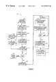
- FIG. 4is a flowchart illustrating the operational flow of one preferred embodiment of FIG. 1;
- FIG. 5is a flowchart illustrating the operational flow of another preferred embodiment of FIG. 1;
- FIG. 6is a functional block diagram of another embodiment of a message data input stage of FIG. 1;
- FIG. 7is a flowchart illustrating the operational flow of one preferred embodiment of the message data input stage of FIG. 6;
- FIG. 8is a flowchart illustrating the operational flow of another preferred embodiment of the message data input stage of FIG. 6;
- FIG. 9is a functional block diagram of another embodiment of the message data input stage of FIG. 1;
- FIG. 10is a functional block diagram of another embodiment of the message broadcast system of the present invention.
- FIG. 11is a flowchart illustrating the operational flow of one preferred embodiment of FIG. 10.
- FIG. 12is a flowchart illustrating the operational flow of another preferred embodiment of FIG. 10 .
- FIG. 1is a functional diagram of one preferred embodiment of the present invention.
- Message broadcast system 10comprises a message data input stage 20 and message data output stage 30 . Included in a preferred embodiment is at least one 12 , and preferably a plurality of message data 12 , 14 , 16 , a central controller 18 and at least one 22 , and preferably a plurality of database systems 22 , 24 , 26 .
- Central controller 18receives message data 12 , via a communications interface, and automatically communicates with and controls database 22 to remove and/or disperse information from database 22 that matches information contained in the message data 12 .
- system 10provides an automated central controller 18 to automatically communicate with and control a plurality of databases 22 , 24 , 26 upon being supplied with message data 12 from a user.
- Each of these functional components of the present embodimentwill be more fully described below.
- message broadcast system 10operates both as an information removal system and an information dispersal system.
- message data 12can be personal identification data (e.g., name, address, email address, phone number, etc.) that is supplied by a user to the central controller 18 and central controller communicates with and controls selected database systems 22 to remove personal identification data therefrom. Included in message data 12 is a request to have the personal identification data removed from systems 22 that supply bulk mailers, bulk emailers and telemarketers with this information.
- database systems 22are marketing warehouse systems used by bulk mailers, bulk emailers and telemarketers. Database systems 22 are selected by the central controller 18 based on the content of the message data, i.e., a request to have an email address, postal address or phone number, or all of the above, removed from the marketing warehouse systems 22 .
- message data 12can be information request data that is supplied by a user to the central controller 18 and central controller communicates with and controls selected database systems 22 to disperse information related to the information request data from the database systems 22 back to the user.
- information request data (message data) 12can be a request for information related to a professional organization (e.g., medical, legal, engineering, etc.), trade organization (e.g., electricians, plumbers, technicians, etc.), civic activities (e.g., voting preference, government actions/bills, etc.), community activities (e.g., conventions, events, etc.), commercial activities (e.g., business transactions, etc.) or any other particularized request for information.
- professional organizatione.g., medical, legal, engineering, etc.
- trade organizatione.g., electricians, plumbers, technicians, etc.
- civic activitiese.g., voting preference, government actions/bills, etc.
- community activitiese.g., conventions, events, etc.
- commercial activities
- database systems 22are database systems that contain such information and are selected by the central controller 18 to forward the information to the user in response to the information request.
- a physiciancan upload a request for information (message data 12 ) on the latest drug for a disease and/or the latest report on a disease and/or latest research on a disease into the central controller 18 to have the central controller 18 automatically communicate with and control a plurality of preselected database systems 22 to forward information in response to the request.
- message data 12shall be understood to comprise information request data and/or personal identification data. Accordingly, database systems 22 shall be understood to be related to the given message data 12 .
- message input stage 20 of FIG. 1is depicted.
- Message data 12is generated by a message data generator 32 .
- Message data generator 32can be a personal computer, email terminal, or the like, or any other means of generating a text message containing personal information.
- message data generator 32is a personal computer used by a customer or user 28 at a remote location.
- message data generator 32also includes processor, memory, input devices, monitor, and anything else associated with a personal computer.
- Message data generator 32also includes a communication interface 34 to communicate with the central controller 18 .
- communication interface 34is a network server interface which permits the user to access the network (e.g., world wide web) and includes email transmissions network communication protocol.
- Communication interfacecould also be a direct dial-up interface via a modem (not shown).
- message data generator 32also includes (not shown) an appropriate web browsing and/or email messaging tool, as are known in the art (e.g. NetscapeTM, Internet ExplorerTM, etc.).
- a customer or user 28supplies message data, via message data generator 32 .
- Message data 12is input into central controller 18 , via communication interface 34 , as will be described below.
- Central controller 18preferably includes a local database 46 , an external database controller 44 and at least one communication interface 36 and 70 to communicate with message data generator 32 and external database systems 22 , respectively. It is important to note at the outset that, although not shown in the figures, central controller 18 and message data generator 32 can communicate directly, via a direct modem link over communication interface 34 and 36 . Preferably, the communication takes place virtually over an external network server, for example, America On-LineTM or ISP (internet service provider), each of which can be controlled by central controller 18 . Of course, to communicate over the network, communication interface 34 and 36 must be appropriately configured for internet protocol, e.g., TCP/IP internet protocol. Thus, for example, communication interface 36 comprises a TCP/IP network interface to communicate with a network server.
- ISPInternet service provider
- Message data 12 originating from at least one, but preferably a plurality of remote message data generators 32is uploaded into central controller 18 and stored in local database 46 .
- message data 12is uploaded to central controller 18 via, as described above, an network server system.
- network servercontrolled by central controller 18 , can provide a user interface to simplify and facilitate message data 12 input from a user 28 (described below).
- central controllerUpon receiving message data 12 , central controller stores the message data 12 in local database 46 .
- Database 22typically comprises a database processor 52 , a communication interface 48 and a database containing message data 54 .
- database 22also comprises associated hardware and software (not shown) associated with database 22 .
- database 22is one of a plurality of remote databases that can be communicated with and controlled by central controller 18 .
- database 22is a preselected database who's identity is stored by central controller 18 on the local database 46 .
- central controller 18Upon receiving and storing message data 12 (described above), central controller 18 initiates communication with database 22 , via communication interface 70 and 48 .
- External database controller 44is a device that is adapted to communicate with and control the external database systems 22 .
- external database controlleris coupled to a local database 46 and a communication interface 70 .
- message data 12is uploaded into central controller 18 and stored on local database 46 .
- local database 46is appropriately configured to initiate communication with external database controller 44 .
- external database controllerinitiates communication with the external database systems 22 , via communications interface 70 and 48 .
- External database controller 44contains appropriate hardware and/or software to control database 22 .
- External database controller 22reads message data 12 contained in local database 46 and, via communication interface 36 , initiates control signals to search database 54 for matching data contained in message data 12 .
- local database 46contains data related to each external database 22 .
- This datapreferably includes communications protocol, control data, handshaking protocol, and other information used by external database controller 44 to communicate with and control each of the preselected database.
- communications protocolpreferably includes communications protocol, control data, handshaking protocol, and other information used by external database controller 44 to communicate with and control each of the preselected database.
- local databasemust be appropriately programmed by an administrator of central controller 18 , as is understood by those skilled in the art.
- central controller 18can be initiated over a direct point-to-point link (e.g., via modem) and/or by a virtual connection over a network server.
- communication interface 36 and 48must be appropriately configured to communicate in such a fashion.
- Central controller 18is adapted to communicate over both mediums, depending on the particular requirements of database 22 .
- FIG. 5is a flow chart 200 illustrating the operational flow of the above-described information dispersal system of the embodiments shown in FIGS. 1-3. Reference shall be made to above-described components without corresponding numbering.
- the system 100begins by a user creating a text message containing information request data 102 .
- the useruploads the message to the central controller 104 , and the central controller stores this message on the local database 108 .
- central controllerdetermines the content of the message data to determine appropriate database systems to communicate with based on the particular information requested 106 .
- central controllerUpon receiving and storing the message, central controller initiates communication with an external (remote) database n 110 .
- Central controllerqueries database n, via control signals initiated by central controller, for information matching the information request 118 .
- Central controllerand more specifically, external database controller determines if a match is found between the user-supplied information request and data contained in the external database 112 . If a match is not found, external database controller initiates communication to another preselected database n+1. If a match is found, central controller controls the external database, based on control signals initiated by the external database controller, to disperse information in that database matching the information request 114 .
- the informationis dispersed directly back to the user, either in hard copy format or in electronic format that can be accessed directly on the message data generator. Alternatively, the information can be dispersed to central controller and stored there until retrieved by the user.
- Central controllerthen initiates communication to another preselected database n+1, and the above process repeats.
- Central controllergenerates a report to user indicating which databases have dispersed information found 116 .
- FIG. 4is a flow chart 100 illustrating the operational flow of the above-described personal identification information removal system of the embodiments shown in FIGS. 1-3. Reference shall be made to above-described components without corresponding numbering.
- the system 200begins by a user creating a text message containing personal ID data 202 .
- the useruploads the message to the central controller 204 , and the central controller stores this message on the local database 208 .
- central controllerdetermines the content of the message data to determine appropriate database systems to communicate with based on the particular personal identification to be removed 206 .
- central controllerUpon receiving and storing the message, central controller initiates communication with an external (remote) database n 208 .
- Central controllerqueries database n, via control signals initiated by central controller, for matching message data 210 .
- Central controllerand more specifically, external database controller determines if a match is found between the user-supplied message data and data contained in the external database 212 . If a match is not found, external database controller initiates communication to another preselected database n+1. If a match is found, central controller controls the external database, based on control signals initiated by the external database controller, to remove information in that database matching the personal identification data 214 . Central controller then initiates communication to another preselected database n+1, and the above process repeats. Central controller generates a report to user indicating which databases had data removed 216 .
- the message broadcast system 10comprises a central controller, a plurality of remote, external databases 22 , 24 , 26 , and a plurality of message data 12 , 14 , 16 generated by a plurality of users 28 .
- message data 12includes preference data or request data indicating the users' preference of having the personal information contained in the message data removed from the database 22 .
- User 28generates message data 12 and uploads message data 12 into central controller 18 , as in the previous embodiment.
- Central controller 18initiates communication with database 22 and uploads message data into database 22 .
- the processrepeats for the next preselected database.
- central controllerdoes not control the database systems, rather an administrator (not shown) of database system 22 removes personal identification data contained in message data from database 22 , in accordance with the request or preference indicated in message data 22 .
- message data input stage 20 ′ of the present inventionis depicted. Its elements operate essentially the same as the message data input stage 20 of the previous embodiment. Additionally, however, message data input stage 20 ′ provides a PIN server 64 , operable over a telephone network 56 via a standard telephone 56 . At its most basic level, PIN server generates a unique PIN access code to each user. The user includes the unique access code when accessing central controller 18 ′ to upload message data 12 ′. Thus, central controller 18 ′ acts as a subscription service system and is available only to users who have valid PIN access code. Each of these functional components will be described below.
- PIN server 64is a remote server typically operated by long distance service providers (e.g., AT&T, Sprint, MCI, etc.) or by local exchange carriers (e.g., NYNEX, etc.) and is generally a random number generator adapted to communicate with both user 28 ′ and central controller 18 ′.
- PIN server 64essentially has two functional components associated with it: PIN server access from a user 28 ′ and PIN server access, update and administration from the central controller 18 ′.
- user 28 ′accesses PIN server 64 by dialing a particular access number (e.g., 900#) over a standard telephone 56 .
- PIN server 64queries user 28 ′ by preferably using an interactive voice response (IVR) system.
- IVRinteractive voice response
- PIN server 64typically, user 28 ′ is requested by PIN server 64 to supply personal information to ensure security, PIN server 64 then issues a unique PIN access code number to that user.
- PIN serveris configured, via the local exchange carrier, to issue a debit to the user's monthly phone record and to issue a corresponding credit report to the central controller 18 ′.
- PIN server 64can be adapted to provide various levels of services based on the user's preference (i.e., a user can be provided with more services by increasing the debit). The various levels of services offered can be administered and controlled by central controller 18 ′.
- user 28 ′uses the PIN access code issued by PIN server 64 to input message data and PIN number 12 ′ using the message data generator 32 ′, as in the previous embodiment.
- User 28 ′uploads message data and PIN 12 ′, via communication interface 34 ′ and 36 ′, into central controller.
- communication interface 34 ′ and 36 ′can be a direct communication or a virtual connection over a network server (internet).
- Message data and PIN 12 ′is stored on local database 46 ′.
- the central controller 18 ′ of this embodimentalso includes a telephone network interface 58 adapted to communicate with and control PIN server 64 aver a standard telephone network 62 .
- Central controller 18 ′routinely accesses PIN server 64 to get pertinent information regarding the status of PIN server, for example, PIN access codes issued, customer (or user 28 ′) account information, customer personal identification data, etc. This status information is stored on local database 46 ′ and is used by central to compare against the information contained in message data 12 ′ to ensure that the person sending the message data 12 ′ is the individual who is granted access to the central controller 18 ′.
- Central controller 18 ′also controls PIN server 64 to facilitate updates and other control functions associated with PIN server 64 .
- central controller 18 ′is appropriately configured to control PIN server 64 to set operational parameters (e.g., user-level access, communication protocol, etc.) and to control various security parameters with the PIN server, as is known in the art.
- central controller 18 ′also has an administration system (not shown) appropriately configured to administer and control both the central controller 18 ′ and the PIN server 64 .
- local database 46 ′stores both message data and PIN 12 ′ and customer account information. To ensure security, local database checks the information in the message data and PIN access code 12 ′ supplied by user 28 ′ against the customer account information supplied by PIN server 64 . If a correct match is found, central controller initiates communication with external database system 22 , via communications interface 70 ′, in accordance with the previous embodiments.
- FIG. 7is a flow chart 300 illustrating the operational flow of the information request system of the above-described embodiment of FIGS. 3 and 6. Reference will be made to above-described components without corresponding numbering.
- Customerdials the appropriate access number over a telephone network to access the PIN server 302 .
- PIN servergrants customer a unique PIN access code 304 .
- PIN serveralso generates a debit bill for service directly to customers phone bill, typically generated by a local exchange carrier 304 .
- customercreates a text message containing information request data and PIN access code 308 .
- Customerinitiates communication with central controller and uploads text message to central controller 310 .
- central controllercommunicates with the PIN server to retrieve valid PIN access codes issued by PIN server for comparison 314 .
- Central controllerupdates the PIN server with current data of valid PIN access codes to ensure that no code is used more than once for a given transaction 316 .
- Central controllercompares text message against information supplied by PIN server to validate the PIN account based on personal identification data contained in the text message 312 . If the comparison is not valid 318 , indicating either that customer has supplied the wrong PIN number or the personal identification associated with the PIN number does not match, central controller generates a message (e.g., email) to customer indicating current status 320 .
- a messagee.g., email
- central controllerstores message data (i.e., personal identification data) in the local database 322 .
- message datai.e., personal identification data
- central controllerupon receiving and storing the message, central controller initiates communication with an external (remote) database n 324 .
- Central controllerqueries database n, via control signals initiated by central controller, for information matching the information request 326 .
- Central controllerand more specifically, external database controller determines if a match is found between the user-supplied information request and data contained in the external database 328 . If a match is not found, external database controller initiates communication to another preselected database n+1.
- central controllercontrols the external database, based on control signals initiated by the external database controller, to disperse information in that database matching the information request 330 .
- Central controllerthen initiates communication to another preselected database n+1, and the above process repeats.
- Central controllergenerates a report to user indicating which databases have dispersed information 332 .
- FIG. 8is a flow chart 400 illustrating the operational flow of the information removal system of the above-described embodiment of FIGS. 3 and 6. Reference will be made to above-described components without corresponding numbering.
- Customerdials the appropriate access number over a telephone network to access the PIN server 402 .
- PIN servergrants customer a unique PIN access code 404 .
- PIN serveralso generates a debit bill for service directly to customers phone bill, typically generated by a local exchange carrier 404 .
- customercreates a text message containing personal identification data and PIN access code 408 .
- Customerinitiates communication with central controller and uploads text message to central controller 410 .
- central controllercommunicates with the PIN server to retrieve valid PIN access codes issued by PIN server for comparison 414 .
- Central controllerupdates the PIN server with current data of valid PIN access codes to ensure that no code is used more than once for a given transaction 416 .
- Central controllercompares text message against information supplied by PIN server to validate the PIN account based on personal identification data contained in the text message 412 . If the comparison is not valid 418 , indicating either that customer has supplied the wrong PIN number or the personal identification associated with the PIN number does not match, central controller generates a message (e.g., email) to customer indicating current status 420 .
- a messagee.g., email
- central controllerstores message data (i.e., personal identification data) in the local database 422 .
- message datai.e., personal identification data
- central controllerupon receiving and storing the message, central controller initiates communication with an external (remote) database n 424 .
- Central controllerqueries database n, via control signals initiated by central controller, for information matching the personal identification data 426 .
- Central controllerand more specifically, external database controller determines if a match is found between the user-supplied information request and data contained in the external database 428 . If a match is not found, external database controller initiates communication to another preselected database n+1.
- central controllercontrols the external database, based on control signals initiated by the external database controller, to remove information in that database matching the personal identification data 430 .
- Central controllerthen initiates communication to another preselected database n+1, and the above process repeats.
- Central controllergenerates a report to user indicating which databases had data removed 432 .
- message data input stage 20 ′′ of the present inventionis depicted. Its elements operate essentially the same as the message data input stage 20 and 20 ′ of the previous embodiments. Additionally, however, message data input stage 20 ′ provides a network server 66 and an administration system 68 , as will be described below. It is to be understood that, although not shown in FIG. 9, central controller 18 ′′ incorporates all of the essential elements as in the previous embodiments, i.e., external database controller 44 , 44 ′.
- this embodimentprovides a system to permit user 28 ′′ to contact network server 66 , access PIN server 64 ′ through the network server 66 , and upload message data and PIN access code 12 ′′ to central controller 18 ′′ directly from the network server 66 .
- customer 28 ′′need not make a separate telephone call to the PIN server 64 ′, rather, customer 28 ′′ can receive a PIN access code and upload message data all on the network server 66 , as explained below.
- customer 28 ′′via massage data generator 32 ′′, communicates with network server 66 to facilitate creation and uploading of message data and PIN access code 12 ′′.
- Network server 66can be a remotely hosted internet site, web page, or the like, that is controlled and maintained by central controller 18 ′′.
- communication interface 34 ′′is appropriately configured to allow message data generator to communicate with network server 66 .
- network server 66is a remotely hosted web page
- communication interface 34 ′′is appropriately configured to interactively communicate with the web page, e.g., via TCP/IP and/or FTP (file transfer protocol).
- Network server 66is appropriately configured to provide customer 28 ′′ with the following functions: interactive text communication (e.g., email), access to PIN server to obtain a PIN account and direct uploading of message data and PIN access code 12 ′′ to central controller 18 ′′.
- network server 66communicates with PIN server 64 ′ to dynamically update PIN server 64 ′ directly from the network server 66 .
- customer 28 ′′ in this embodimentcan change or alter PIN access code data and accompanying message data.
- the customer 28 ′′can access PIN server 64 ′ to obtain PIN access code, create message data (including PIN access code) and upload this information directly to central controller 18 ′′ all in one step.
- PIN server 64 ′can be appropriately configured to generate a debit report directly to the user's 28 ′′ telephone bill. Or, PIN server 64 ′ can be appropriately configured to accept debit financial transaction directly on the network server 66 (e.g., customer 28 ′′ supplies the network server 66 with a credit card account number). PIN server also 64 ′ generates a credit report to central controller and credits an account that is set up on PIN server 64 ′ having the central controller 18 ′ as the beneficiary of the funds received.
- central controller 18 ′′connects to network server 66 via appropriately configured communication interface 36 ′′.
- central controller 18 ′′is the controller of network server 66 , and thus, unlike user 28 ′′, is granted full access and control over network server 66 and PIN server 64 ′.
- an administration system 68is provided to facilitate control and maintenance of network server 66 , PIN server 64 ′ and central controller 18 ′′.
- Administration system 68provides an administrator (not shown) access to local database 46 ′′ for local programming and administrative functions.
- administrative system 68connects to network server to program and administer network server 66 and provide customer 28 ′′ parameters, PIN server access and programming and general localized control over network server, as is known in the art. Only central controller 18 ′′, via administration system 68 , has the ability to change parameters of the network server 66 and PIN server 64 ′, thus, central controller has global control over network server 66 and PIN server 64 ′ to set parameters for customer-level access.
- central controller 18 ′′initiates communication to external database 22 , to upload and/or control external database system 22 in accordance with the previous embodiments of the message data output stage 30 of the present invention as depicted in FIG. 3 .
- FIG. 10depicts another embodiment of the message broadcast system 10 ′ of the present invention and includes communication between central controller 18 ′′, message data generator 32 ′′ and database systems 22 ′ entirely over a network server 66 .
- Message data input stage 20 ′′ of FIG. 9(described above) is incorporated into FIG. 10 .
- communication interface 48 ′ of database system 22 ′is adapted to communicate with the network server, as described above with reference to communication interface 34 ′′ and 36 ′′.
- communication interface 36 ′′ of central controller 18 ′′is appropriately configured to permit communication and control of database systems 22 directly over the network server.
- database system 22 ′can be appropriately controlled by the central controller 18 ′′ to forward information directly to the message data generator over the network server 66 , without having to pass through the central controller 18 ′′.
- FIG. 11is a flow chart 600 illustrating the operational flow of the information dispersal system of the above-described embodiment of FIG. 10 .
- Customercontacts network server to access the pin server 602 .
- PIN serverThrough interactive communication over the network server, customer is granted a unique PIN access code 604 .
- PIN serveralso generates a debit bill for service directly to customer's phone bill or by a financial transaction over the network server 604 .
- Customercreates a text message, either locally on the message data generator or virtually on the network server, that includes the PIN access code granted by PIN server and information request data 606 .
- Customerinitiates communication with central controller and uploads text message to central controller 608 .
- network serveris in communication with central controller, preferably, network server automatically forwards the text message to central controller.
- customerpreferably need not make a separate communication with central controller, rather network server provides a direct on-line connection to central controller via, e.g., a web page server.
- central controllercompares text message to information supplied by PIN server to validate the PIN account based on personal identification data contained in the text message 610 (i.e., using PIN server access and updating 612 and 614 , respectively). If the comparison is not valid 616 , indicating either that customer has supplied the wrong PIN number or the personal identification associated with the PIN number does not match, central controller generates a message (e.g., email) to customer indicating current status.
- a messagee.g., email
- central controllerstores message data in the local database 620 .
- central controllerUpon receiving and storing the message, central controller initiates communication with an external (remote) database n 622 over the network server.
- Central controllerqueries database n, using control signals supplied by central controller over the network server, for information matching the information request data 624 .
- Central controllerand more specifically, external database controller determines if a match is found between message data and data contained in the external database 626 . If a match is not found, external database controller initiates communication to another preselected database n+1. If a match is found, central controller controls the external database (over the network server), based on control signals initiated by the external database controller, to disperse information in that database matching the information request data 628 .
- central controllercontrols the database to disperse the appropriate information directly over the network server to the message data generator (and, ultimately, to the customer). External database controller then initiates communication to another preselected database n+1, and the above process repeats. After all of the preselected external databases are contacted by central controller, central controller generates a report to user indicating which databases dispersed information 630 .
- FIG. 12is a flow chart 700 illustrating the operational flow of the information removal system of the above-described embodiment of FIG. 10 .
- Customercontacts network server to access the pin server 702 .
- PIN serverThrough interactive communication over the network server, customer is granted a unique PIN access code 704 .
- PIN serveralso generates a debit bill for service directly to customer's phone bill or by a financial transaction over the network server 704 .
- Customercreates a text message, either locally on the message data generator or virtually on the network server, that includes the PIN access code granted by PIN server and personal identification data 706 .
- Customerinitiates communication with central controller and uploads text message to central controller 708 .
- network serveris in communication with central controller and network server automatically forwards the text message to central controller.
- customerpreferably need not make a separate communication with central controller, rather network server provides a direct on-line connection to central controller via, e.g., a web page server.
- central controllercompares text message to information supplied by PIN server to validate the PIN account based on personal identification data contained in the text message 710 (i.e., using PIN server access and updating 612 and 614 , respectively). If the comparison is not valid 716 , indicating either that customer has supplied the wrong PIN number or the personal identification associated with the PIN number does not match, central controller generates a message (e.g., email) to customer indicating current status.
- a messagee.g., email
- central controllerstores message data in the local database 720 .
- central controllerUpon receiving and storing the message, central controller initiates communication with an external (remote) database n 722 over the network server.
- Central controllerqueries database n, using control signals supplied by central controller over the network server, for information matching the personal identification data 724 .
- Central controllerand more specifically, external database controller determines if a match is found between message data and data contained in the external database 726 . If a match is not found, external database controller initiates communication to another preselected database n+1. If a match is found, central controller controls the external database (over the network server), based on control signals initiated by the external database controller, to remove information in that database matching the personal identification data 728 . External database controller then initiates communication to another preselected database n+1, and the above process repeats. After all of the preselected external databases are contacted by central controller, central controller generates a report to customer indicating which databases had personal identification data removed 730 .
- central controller 18 , 18 ′ and 18 ′′is adapted to contain optimal searching parameters of database systems 22 for information removal and/or dispersal. Optimal searching is based on the specific content of message data 12 , 12 ′, 12 ′′ and also the specific database system 22 , 22 ′ to be controlled by central controller.
- central controller 18 , 18 ′ and 18 ′′is adapted to interpret message data 12 , 12 ′, 12 ′′ to recognize the specific data contained therein. Interpretation of message data 12 , 12 ′, 12 ′′ can be based on specific text search strings initiated by central controller so that central controller can make an optimal decision for information searching and/or removal.
- central controller 18 , 18 ′ and 18 ′′is adapted to optimally control database systems 22 , 22 ′ based on the message data and also based on the particular database system to be controlled.
- central controlleris adapted to contain optimal searching parameters of a plurality of database systems 22 , 22 ′ and further to implement such parameters in an automatic fashion.
- the information dispersal system of the present inventionis intended to facilitate refined searching and dispersal of information from a plurality of preselected, specialized database systems 22 , 22 ′.
- the present inventioncan provide specialized, efficient information dispersal for medical professionals, legal professionals, trade professionals, localized civic events, voting preferences and voting histories of senators, congressmen at both national and local levels, specific commercial activities, and any other specialized transaction where a user requires specific information on a specific topic.
- Central controlleris therefore adapted to contain control information for a plurality of preselected database systems related to the specialized information requested. To that end, central control is adapted to interpret the incoming message to optimally find the correct information desired.
- central controllercan provide a user interface that restricts the users' information input, thereby inherently refining the search parameters. This can be accomplished, for example, by providing a web-page interface that requires the user to “pigeon-hole” an information request by requiring progressive refinements.
- central controllercan be adapted to read the message data in directly and scan the text for specific text strings or words that indicate the information request. Either way, central controller initiates communication and control of the database systems based on the message data content.
- central controllervia administration system, is continually updated with new database systems that can be controlled by central controller and that fit into a specific category of user information requests.
- central controller 18 , 18 ′ or 18 ′′There are certain direct marketing database systems that cannot communicate with the central controller 18 , 18 ′ or 18 ′′.
- certain database systemsrequire a written (i.e., hardcopy) removal request before removing personal identification data therefrom.
- central controller 18 , 18 ′ and 18 ′′can be appropriately modified to communicate with certain ones of the preselected database systems that are adapted to generate a hardcopy message and supply these certain database systems with the appropriate location information indicating where to forward the hardcopy message.
- Local database 46 , 46 ′, 46 ′′has been described above as containing information generated from user 28 , 28 ′, 28 ′′, and database system 22 , but local database 46 , 46 ′, 46 ′′ can also be appropriately configured to contain control data related to PIN server 64 , 64 ′ and network server 66 .
- local database 46 , 46 ′, 46 ′′can be separate databases, each separately containing the above-described parameters, or local database 46 , 46 ′, 46 ′′ can be one unified database appropriately programmed to contain these parameters in the appropriate format.
- Optimal search parameters based on the particular message data received and the particular database to be controlledcan also be stored on the local database 46 , 46 ′, 46 ′′ and preferably operate in conjunction with the external database controller 44 , 44 ′ to permit optimal control of the external database systems from the central controller.
- storingis only an operational parameter of maintaining the message data locally (i.e., local to the central controller).
- storing the message dataneed not be an additional process that requires additional hardware, but can merely be performed locally in ROM or RAM when the message data is uploaded by the message data generator.
- External database controller 44 , 44 ′is appropriately programmed to facilitate communication with and control of external database systems 22 .
- administration systemcan be appropriately configured so as to have global control external database controller 44 , 44 ′.
- Processor 38 , 38 ′is configured to generally control local database and external database controller, and can be a standard off-the-shelf process (e.g., Pentium, RISC) or a customized processor (e.g., PLD), as is known by those skilled in the art.
- processor 38 , 38 ′has associated ROM/RAM system 42 , 42 ′ for local information processing.
- central controller and administration system 68can be separate components or all part of one unified system.
- central controller 18 , 18 ′ and 18 ′′ of the present inventioncan be implemented with various hardware, software, or any combination thereof, without departing from the scope of the present invention.
- central controller 18 , 18 ′ and 18 ′′is implemented with a high-speed computer system and control software that has general applicability to many control scenarios for controlling the database systems heretofore described.
- central controller 18 , 18 ′ and 18 ′′can be adapted to communicate over the network using a T1 and/or T3 communication system.
- central controller 18 , 18 ′ and 18 ′′can be adapted to permit real-time user interactivity, thus permitting a user to complete the entire transaction (e.g., information removal and/or information dispersal) at one time.
- network server 66can be a preprogrammed internet web page having a user interface that supplies an email messaging system and a direct link to central controller 18 , 18 ′, 18 ′′.
- network servercan be appropriately configured to provide a “fill-in-the-blanks” text message interface for the user.
- PIN server 64 ′is programmed by administration system 68 to communicate with network server and further to provide administrative control over PIN server 64 ′, via network server 66 .
- central controller 18 ′′has global control over parameters offered by PIN server 64 .
- the present inventionis of broad scope intended to cover centralized transactions where an information dispersal system has advantages over the art.
- the present inventioncan be utilized as a centralized commercial transaction system whereby users (or customers) can engage in a variety of commercial transactions using the aforementioned information dispersal system of the present invention.
- Some examplesinclude travel information, greeting card services, news and news related information, etc.
- the information dispersal system of the present inventioncan be adapted to permit a variety of other transactions.
- the present inventioncan be utilized as a means of posting a single resume from a job applicant to all appropriate job banks in any geographically remote database systems, as requested by the applicant.
- the present inventionis intended to permit message broadcasting (information removal and/or information dispersal) from a centralized controller to access to a variety of geographically remote database systems, depending on the particular request from the user.
- central controllermust be appropriately programmed to connect with the particular databases systems, as described herein.
- the present inventionis intended to cover all such applications of the information dispersal system described herein, as set forth in the appending claims.
Landscapes
- Engineering & Computer Science (AREA)
- Business, Economics & Management (AREA)
- Strategic Management (AREA)
- Entrepreneurship & Innovation (AREA)
- Human Resources & Organizations (AREA)
- Computer Networks & Wireless Communication (AREA)
- Signal Processing (AREA)
- Theoretical Computer Science (AREA)
- Development Economics (AREA)
- Finance (AREA)
- Economics (AREA)
- Marketing (AREA)
- Accounting & Taxation (AREA)
- General Physics & Mathematics (AREA)
- General Business, Economics & Management (AREA)
- Physics & Mathematics (AREA)
- Tourism & Hospitality (AREA)
- Quality & Reliability (AREA)
- Computer Security & Cryptography (AREA)
- Operations Research (AREA)
- Data Mining & Analysis (AREA)
- Computer Hardware Design (AREA)
- Game Theory and Decision Science (AREA)
- Information Transfer Between Computers (AREA)
- Financial Or Insurance-Related Operations Such As Payment And Settlement (AREA)
- Telephonic Communication Services (AREA)
Abstract
Description
Claims (11)
Priority Applications (5)
| Application Number | Priority Date | Filing Date | Title |
|---|---|---|---|
| US08/956,743US6370139B2 (en) | 1997-10-24 | 1997-10-24 | System and method for providing information dispersal in a networked computing environment |
| PCT/US1998/022357WO1999022317A2 (en) | 1997-10-24 | 1998-10-22 | Message broadcast system |
| US09/295,000US7301944B1 (en) | 1997-10-24 | 1999-04-16 | Media file distribution with adaptive transmission protocols |
| US10/118,458US20070108073A1 (en) | 1997-10-24 | 2002-04-08 | Message broadcast system |
| US11/926,072US20080120430A1 (en) | 1997-10-24 | 2007-10-28 | Peered Content Distribution |
Applications Claiming Priority (1)
| Application Number | Priority Date | Filing Date | Title |
|---|---|---|---|
| US08/956,743US6370139B2 (en) | 1997-10-24 | 1997-10-24 | System and method for providing information dispersal in a networked computing environment |
Related Child Applications (2)
| Application Number | Title | Priority Date | Filing Date |
|---|---|---|---|
| US09/295,000Continuation-In-PartUS7301944B1 (en) | 1997-10-24 | 1999-04-16 | Media file distribution with adaptive transmission protocols |
| US10/118,458ContinuationUS20070108073A1 (en) | 1997-10-24 | 2002-04-08 | Message broadcast system |
Publications (2)
| Publication Number | Publication Date |
|---|---|
| US20010043599A1 US20010043599A1 (en) | 2001-11-22 |
| US6370139B2true US6370139B2 (en) | 2002-04-09 |
Family
ID=25498645
Family Applications (2)
| Application Number | Title | Priority Date | Filing Date |
|---|---|---|---|
| US08/956,743Expired - LifetimeUS6370139B2 (en) | 1997-10-24 | 1997-10-24 | System and method for providing information dispersal in a networked computing environment |
| US10/118,458AbandonedUS20070108073A1 (en) | 1997-10-24 | 2002-04-08 | Message broadcast system |
Family Applications After (1)
| Application Number | Title | Priority Date | Filing Date |
|---|---|---|---|
| US10/118,458AbandonedUS20070108073A1 (en) | 1997-10-24 | 2002-04-08 | Message broadcast system |
Country Status (2)
| Country | Link |
|---|---|
| US (2) | US6370139B2 (en) |
| WO (1) | WO1999022317A2 (en) |
Cited By (64)
| Publication number | Priority date | Publication date | Assignee | Title |
|---|---|---|---|---|
| US20010049745A1 (en)* | 2000-05-03 | 2001-12-06 | Daniel Schoeffler | Method of enabling transmission and reception of communication when current destination for recipient is unknown to sender |
| US20010053986A1 (en)* | 2000-06-19 | 2001-12-20 | Dick Richard S. | Method and apparatus for requesting, retrieving, and normalizing medical information |
| US20020103854A1 (en)* | 1998-08-28 | 2002-08-01 | Landscape Company, Limited. | Personal data management apparatus and personal data management method |
| US20020116227A1 (en)* | 2000-06-19 | 2002-08-22 | Dick Richard S. | Method and apparatus for requesting, retrieving, and obtaining de-identified medical informatiion |
| US20020169863A1 (en)* | 2001-05-08 | 2002-11-14 | Robert Beckwith | Multi-client to multi-server simulation environment control system (JULEP) |
| US20020169841A1 (en)* | 1996-05-31 | 2002-11-14 | Microsoft | Method for automatically implementing special forms in an e-mail system |
| US20020198942A1 (en)* | 2001-06-20 | 2002-12-26 | Ryan Barbara Rae | Method and system for reducing unsolicited communications via multiple channels of communication |
| US20030069946A1 (en)* | 2001-10-05 | 2003-04-10 | Adc Telecommunications, Inc. | Central directory server |
| US20030069884A1 (en)* | 2001-10-05 | 2003-04-10 | Ajit Nair | Database structure |
| US20030069965A1 (en)* | 2001-10-05 | 2003-04-10 | Adc Telecommunications, Inc. | Provisioning per cable modem |
| US20030070063A1 (en)* | 2001-10-05 | 2003-04-10 | Adc Telecommunications, Inc. | Configuration file caching |
| US20030069948A1 (en)* | 2001-10-05 | 2003-04-10 | Donghai Ma | Automated online subscription |
| US6658400B2 (en)* | 1999-12-04 | 2003-12-02 | William S. Perell | Data certification and verification system having a multiple-user-controlled data interface |
| US20040019646A1 (en)* | 2002-03-18 | 2004-01-29 | Monte Zweben | Methods and systems for providing an on-line interaction manager |
| US6795537B1 (en)* | 1999-12-28 | 2004-09-21 | Bellsouth Intellectual Property Corporation | Method for updating a database using a telephone |
| US20050147221A1 (en)* | 2003-12-30 | 2005-07-07 | Aoki Norihiro E. | Method and apparatus for managing subscription-type messages |
| US20060167823A1 (en)* | 2004-12-31 | 2006-07-27 | William York | Secure wireless commerce |
| US20060271456A1 (en)* | 2005-05-26 | 2006-11-30 | Romain Martin R | Debit-based identity theft monitoring and prevention |
| US7281263B1 (en)* | 2001-02-23 | 2007-10-09 | Sprint Communications Company L.P. | System and method for managing security access for users to network systems |
| US20080120430A1 (en)* | 1997-10-24 | 2008-05-22 | Redmond Scott D | Peered Content Distribution |
| US20090216605A1 (en)* | 2004-05-05 | 2009-08-27 | Fluor Technologies Corporation | Integrated Acceptance Testing |
| US7672998B1 (en) | 2000-05-16 | 2010-03-02 | Ziplink, Inc. | Apparatus and methods for controlling the transmission of messages |
| US20100217796A1 (en)* | 2007-10-09 | 2010-08-26 | Cleversafe, Inc. | Integrated client for use with a dispersed data storage network |
| US20100327055A1 (en)* | 1998-02-17 | 2010-12-30 | Yik Hei Sia | Code Based Access Systems |
| US20120185549A1 (en)* | 2001-02-20 | 2012-07-19 | Mcafee, Inc. | Unwanted E-Mail Filtering System Including Voting Feedback |
| US20130318033A1 (en)* | 2012-05-24 | 2013-11-28 | Rudolf Pohlan | Method for Operating an Automation Device |
| US9246860B2 (en) | 2006-02-09 | 2016-01-26 | Mcafee, Inc. | System, method and computer program product for gathering information relating to electronic content utilizing a DNS server |
| US9762550B2 (en) | 2001-01-02 | 2017-09-12 | Tranz-Send Broadcasting Network, Inc. | Low latency active noise cancellation system with client intercommunication |
| US20170279971A1 (en)* | 2009-01-28 | 2017-09-28 | Headwater Research Llc | Mobile Device and Service Management |
| US20180167413A1 (en)* | 2009-01-28 | 2018-06-14 | Headwater Research Llc | Wireless Network Service Interfaces |
| US10070305B2 (en) | 2009-01-28 | 2018-09-04 | Headwater Research Llc | Device assisted services install |
| US10171988B2 (en) | 2009-01-28 | 2019-01-01 | Headwater Research Llc | Adapting network policies based on device service processor configuration |
| US10171990B2 (en) | 2009-01-28 | 2019-01-01 | Headwater Research Llc | Service selection set publishing to device agent with on-device service selection |
| US10171995B2 (en) | 2013-03-14 | 2019-01-01 | Headwater Research Llc | Automated credential porting for mobile devices |
| US10171681B2 (en) | 2009-01-28 | 2019-01-01 | Headwater Research Llc | Service design center for device assisted services |
| US10200541B2 (en) | 2009-01-28 | 2019-02-05 | Headwater Research Llc | Wireless end-user device with divided user space/kernel space traffic policy system |
| US10237146B2 (en) | 2009-01-28 | 2019-03-19 | Headwater Research Llc | Adaptive ambient services |
| US10237773B2 (en) | 2009-01-28 | 2019-03-19 | Headwater Research Llc | Device-assisted services for protecting network capacity |
| US10248996B2 (en) | 2009-01-28 | 2019-04-02 | Headwater Research Llc | Method for operating a wireless end-user device mobile payment agent |
| US10320990B2 (en)* | 2009-01-28 | 2019-06-11 | Headwater Research Llc | Device assisted CDR creation, aggregation, mediation and billing |
| US10321320B2 (en) | 2009-01-28 | 2019-06-11 | Headwater Research Llc | Wireless network buffered message system |
| US10326675B2 (en) | 2009-01-28 | 2019-06-18 | Headwater Research Llc | Flow tagging for service policy implementation |
| US10462627B2 (en) | 2009-01-28 | 2019-10-29 | Headwater Research Llc | Service plan design, user interfaces, application programming interfaces, and device management |
| US10492102B2 (en) | 2009-01-28 | 2019-11-26 | Headwater Research Llc | Intermediate networking devices |
| US10536983B2 (en) | 2009-01-28 | 2020-01-14 | Headwater Research Llc | Enterprise access control and accounting allocation for access networks |
| US10681179B2 (en) | 2009-01-28 | 2020-06-09 | Headwater Research Llc | Enhanced curfew and protection associated with a device group |
| US10716006B2 (en) | 2009-01-28 | 2020-07-14 | Headwater Research Llc | End user device that secures an association of application to service policy with an application certificate check |
| US10715342B2 (en) | 2009-01-28 | 2020-07-14 | Headwater Research Llc | Managing service user discovery and service launch object placement on a device |
| US10771980B2 (en) | 2009-01-28 | 2020-09-08 | Headwater Research Llc | Communications device with secure data path processing agents |
| US10779177B2 (en) | 2009-01-28 | 2020-09-15 | Headwater Research Llc | Device group partitions and settlement platform |
| US10783581B2 (en) | 2009-01-28 | 2020-09-22 | Headwater Research Llc | Wireless end-user device providing ambient or sponsored services |
| US10791471B2 (en) | 2009-01-28 | 2020-09-29 | Headwater Research Llc | System and method for wireless network offloading |
| US10798252B2 (en) | 2009-01-28 | 2020-10-06 | Headwater Research Llc | System and method for providing user notifications |
| US10841839B2 (en) | 2009-01-28 | 2020-11-17 | Headwater Research Llc | Security, fraud detection, and fraud mitigation in device-assisted services systems |
| US10985977B2 (en) | 2009-01-28 | 2021-04-20 | Headwater Research Llc | Quality of service for device assisted services |
| US11218854B2 (en) | 2009-01-28 | 2022-01-04 | Headwater Research Llc | Service plan design, user interfaces, application programming interfaces, and device management |
| US11412366B2 (en) | 2009-01-28 | 2022-08-09 | Headwater Research Llc | Enhanced roaming services and converged carrier networks with device assisted services and a proxy |
| US11966464B2 (en) | 2009-01-28 | 2024-04-23 | Headwater Research Llc | Security techniques for device assisted services |
| US11973804B2 (en) | 2009-01-28 | 2024-04-30 | Headwater Research Llc | Network service plan design |
| US11985155B2 (en) | 2009-01-28 | 2024-05-14 | Headwater Research Llc | Communications device with secure data path processing agents |
| US12137004B2 (en) | 2009-01-28 | 2024-11-05 | Headwater Research Llc | Device group partitions and settlement platform |
| US12389218B2 (en) | 2009-01-28 | 2025-08-12 | Headwater Research Llc | Service selection set publishing to device agent with on-device service selection |
| US12388810B2 (en) | 2009-01-28 | 2025-08-12 | Headwater Research Llc | End user device that secures an association of application to service policy with an application certificate check |
| US12432130B2 (en) | 2009-01-28 | 2025-09-30 | Headwater Research Llc | Flow tagging for service policy implementation |
Families Citing this family (20)
| Publication number | Priority date | Publication date | Assignee | Title |
|---|---|---|---|---|
| WO2001038999A1 (en)* | 1999-11-23 | 2001-05-31 | Escom Corporation | Electronic message filter having a whitelist database and a quarantining mechanism |
| EP1133101A1 (en)* | 2000-03-07 | 2001-09-12 | BRITISH TELECOMMUNICATIONS public limited company | Data distribution |
| US20020055876A1 (en)* | 2000-11-07 | 2002-05-09 | Thilo Gabler | Method and apparatus for interactive advertising using user responses |
| NL1018494C2 (en) | 2001-07-09 | 2003-01-10 | Koninkl Kpn Nv | Method and system for delivering a service to a client through a service process. |
| US7283830B2 (en)* | 2002-01-29 | 2007-10-16 | Motricity, Inc. | Wireless device hub system and method |
| US7574447B2 (en) | 2003-04-08 | 2009-08-11 | United Parcel Service Of America, Inc. | Inbound package tracking systems and methods |
| US7305404B2 (en)* | 2003-10-21 | 2007-12-04 | United Parcel Service Of America, Inc. | Data structure and management system for a superset of relational databases |
| JP4711954B2 (en)* | 2004-03-04 | 2011-06-29 | 株式会社Access | Wireless communication terminal synchronization method, wireless communication system, wireless communication terminal, and server |
| US20050267821A1 (en)* | 2004-05-14 | 2005-12-01 | United Parcel Service Of America, Inc. | Address validation mode switch |
| US20060101124A1 (en)* | 2004-11-10 | 2006-05-11 | Landis Michael D | Method and apparatus for mass email transmission |
| US7542972B2 (en)* | 2005-01-28 | 2009-06-02 | United Parcel Service Of America, Inc. | Registration and maintenance of address data for each service point in a territory |
| US9569772B2 (en)* | 2005-12-21 | 2017-02-14 | Patent Navigation Inc | Enhancing bank card security with a mobile device |
| US9001673B2 (en)* | 2009-12-29 | 2015-04-07 | Ebay Inc. | Outgoing communications inventory |
| US20120084152A1 (en)* | 2010-10-01 | 2012-04-05 | Marlimar Interactive, Llc | Offer Message Flow System |
| US9811837B2 (en) | 2012-06-29 | 2017-11-07 | Mastercard International Incorporated | System and method for setting a product watch on transaction data |
| US9934511B2 (en) | 2012-06-29 | 2018-04-03 | Mastercard International Incorporated | System and method for determining merchant location and availability using transaction data |
| US10332088B2 (en) | 2012-08-01 | 2019-06-25 | Mastercard International Incorporated | System and method for setting a hot product alert on transaction data |
| US9785945B2 (en) | 2012-08-01 | 2017-10-10 | Mastercard International Incorporated | System and method for preventing multiple refunds and chargebacks |
| US9818152B2 (en) | 2012-10-18 | 2017-11-14 | Mastercard International Incorporated | System and method for allowing forward-sold goods purchased via credit/debit card to be resold |
| US10742046B2 (en)* | 2012-12-03 | 2020-08-11 | ChargeItSpot, LLC | System and method for providing interconnected and secure mobile device charging stations |
Citations (11)
| Publication number | Priority date | Publication date | Assignee | Title |
|---|---|---|---|---|
| US4818984A (en) | 1986-11-26 | 1989-04-04 | American Telephone And Telegraph Company, At&T Bell Laboratories | Broadcasting messages in a distributed processing system |
| US4845658A (en) | 1986-12-01 | 1989-07-04 | Massachusetts Institute Of Technology | Information method and apparatus using simplex and duplex communications |
| US5036518A (en) | 1988-11-02 | 1991-07-30 | Tseung Lawrence C N | Guaranteed reliable broadcast network |
| US5077830A (en) | 1988-02-17 | 1991-12-31 | Indesys, Inc. | Method and apparatus to selectively address recipients and recover missing messages on a broadcast distribution network |
| US5247664A (en)* | 1991-03-28 | 1993-09-21 | Amoco Corporation | Fault-tolerant distributed database system and method for the management of correctable subtransaction faults by the global transaction source node |
| US5742905A (en)* | 1994-09-19 | 1998-04-21 | Bell Communications Research, Inc. | Personal communications internetworking |
| US5826261A (en)* | 1996-05-10 | 1998-10-20 | Spencer; Graham | System and method for querying multiple, distributed databases by selective sharing of local relative significance information for terms related to the query |
| US5859972A (en)* | 1996-05-10 | 1999-01-12 | The Board Of Trustees Of The University Of Illinois | Multiple server repository and multiple server remote application virtual client computer |
| US5881232A (en)* | 1996-07-23 | 1999-03-09 | International Business Machines Corporation | Generic SQL query agent |
| US5884312A (en)* | 1997-02-28 | 1999-03-16 | Electronic Data Systems Corporation | System and method for securely accessing information from disparate data sources through a network |
| US5890129A (en)* | 1997-05-30 | 1999-03-30 | Spurgeon; Loren J. | System for exchanging health care insurance information |
Family Cites Families (8)
| Publication number | Priority date | Publication date | Assignee | Title |
|---|---|---|---|---|
| US6202058B1 (en)* | 1994-04-25 | 2001-03-13 | Apple Computer, Inc. | System for ranking the relevance of information objects accessed by computer users |
| US5845255A (en)* | 1994-10-28 | 1998-12-01 | Advanced Health Med-E-Systems Corporation | Prescription management system |
| EP0733967B1 (en)* | 1995-03-24 | 2005-02-09 | Hewlett-Packard Company, A Delaware Corporation | Methods and apparatus for monitoring events and implementing corrective action in a multi-entity computer system |
| US5790793A (en)* | 1995-04-04 | 1998-08-04 | Higley; Thomas | Method and system to create, transmit, receive and process information, including an address to further information |
| US6112186A (en)* | 1995-06-30 | 2000-08-29 | Microsoft Corporation | Distributed system for facilitating exchange of user information and opinion using automated collaborative filtering |
| US5995938A (en)* | 1996-02-27 | 1999-11-30 | Whaley; Susan S. | Medication compliance system |
| US6249772B1 (en)* | 1997-07-08 | 2001-06-19 | Walker Digital, Llc | Systems and methods wherein a buyer purchases a product at a first price and acquires the product from a merchant that offers the product for sale at a second price |
| US6606657B1 (en)* | 1999-06-22 | 2003-08-12 | Comverse, Ltd. | System and method for processing and presenting internet usage information |
- 1997
- 1997-10-24USUS08/956,743patent/US6370139B2/ennot_activeExpired - Lifetime
- 1998
- 1998-10-22WOPCT/US1998/022357patent/WO1999022317A2/enactiveApplication Filing
- 2002
- 2002-04-08USUS10/118,458patent/US20070108073A1/ennot_activeAbandoned
Patent Citations (11)
| Publication number | Priority date | Publication date | Assignee | Title |
|---|---|---|---|---|
| US4818984A (en) | 1986-11-26 | 1989-04-04 | American Telephone And Telegraph Company, At&T Bell Laboratories | Broadcasting messages in a distributed processing system |
| US4845658A (en) | 1986-12-01 | 1989-07-04 | Massachusetts Institute Of Technology | Information method and apparatus using simplex and duplex communications |
| US5077830A (en) | 1988-02-17 | 1991-12-31 | Indesys, Inc. | Method and apparatus to selectively address recipients and recover missing messages on a broadcast distribution network |
| US5036518A (en) | 1988-11-02 | 1991-07-30 | Tseung Lawrence C N | Guaranteed reliable broadcast network |
| US5247664A (en)* | 1991-03-28 | 1993-09-21 | Amoco Corporation | Fault-tolerant distributed database system and method for the management of correctable subtransaction faults by the global transaction source node |
| US5742905A (en)* | 1994-09-19 | 1998-04-21 | Bell Communications Research, Inc. | Personal communications internetworking |
| US5826261A (en)* | 1996-05-10 | 1998-10-20 | Spencer; Graham | System and method for querying multiple, distributed databases by selective sharing of local relative significance information for terms related to the query |
| US5859972A (en)* | 1996-05-10 | 1999-01-12 | The Board Of Trustees Of The University Of Illinois | Multiple server repository and multiple server remote application virtual client computer |
| US5881232A (en)* | 1996-07-23 | 1999-03-09 | International Business Machines Corporation | Generic SQL query agent |
| US5884312A (en)* | 1997-02-28 | 1999-03-16 | Electronic Data Systems Corporation | System and method for securely accessing information from disparate data sources through a network |
| US5890129A (en)* | 1997-05-30 | 1999-03-30 | Spurgeon; Loren J. | System for exchanging health care insurance information |
Non-Patent Citations (1)
| Title |
|---|
| "The Best WIN 95 and NT Sites, Services & Utilities" Internet Explorer Shareware Windows Sources; www.winsources.com; Oct. 1997; p. 140. |
Cited By (129)
| Publication number | Priority date | Publication date | Assignee | Title |
|---|---|---|---|---|
| US6993563B2 (en) | 1996-05-31 | 2006-01-31 | Microsoft Corporation | System and method for composing, processing, and organizing electronic mail message items |
| US7523222B2 (en) | 1996-05-31 | 2009-04-21 | Microsoft Corporation | Method for automatically implementing special forms in an e-mail system |
| US20020169841A1 (en)* | 1996-05-31 | 2002-11-14 | Microsoft | Method for automatically implementing special forms in an e-mail system |
| US20060168067A1 (en)* | 1996-05-31 | 2006-07-27 | Microsoft Corporation | Method for automatically implementing special forms in an e-mail system |
| US7010616B2 (en) | 1996-05-31 | 2006-03-07 | Microsoft Corporation | Method for automatically implementing special forms in an e-mail system |
| US6549950B2 (en)* | 1996-05-31 | 2003-04-15 | Microsoft Corporation | Method for automatically tallying voting data in e-mail systems |
| US20030120737A1 (en)* | 1996-05-31 | 2003-06-26 | Microsoft Corporation | System and method for composing, processing, and organizing electronic mail message items |
| US20080120430A1 (en)* | 1997-10-24 | 2008-05-22 | Redmond Scott D | Peered Content Distribution |
| US20100327055A1 (en)* | 1998-02-17 | 2010-12-30 | Yik Hei Sia | Code Based Access Systems |
| US20020103854A1 (en)* | 1998-08-28 | 2002-08-01 | Landscape Company, Limited. | Personal data management apparatus and personal data management method |
| US6658400B2 (en)* | 1999-12-04 | 2003-12-02 | William S. Perell | Data certification and verification system having a multiple-user-controlled data interface |
| US6795537B1 (en)* | 1999-12-28 | 2004-09-21 | Bellsouth Intellectual Property Corporation | Method for updating a database using a telephone |
| US20010049745A1 (en)* | 2000-05-03 | 2001-12-06 | Daniel Schoeffler | Method of enabling transmission and reception of communication when current destination for recipient is unknown to sender |
| US7672998B1 (en) | 2000-05-16 | 2010-03-02 | Ziplink, Inc. | Apparatus and methods for controlling the transmission of messages |
| US8271596B1 (en) | 2000-05-16 | 2012-09-18 | Ziplink, Inc. | Apparatus and methods for controlling the transmission of messages |
| US20010053986A1 (en)* | 2000-06-19 | 2001-12-20 | Dick Richard S. | Method and apparatus for requesting, retrieving, and normalizing medical information |
| US20020111833A1 (en)* | 2000-06-19 | 2002-08-15 | Dick Richard S. | Method and apparatus for requesting and retrieving de-identified medical information |
| US20020116227A1 (en)* | 2000-06-19 | 2002-08-22 | Dick Richard S. | Method and apparatus for requesting, retrieving, and obtaining de-identified medical informatiion |
| US9762550B2 (en) | 2001-01-02 | 2017-09-12 | Tranz-Send Broadcasting Network, Inc. | Low latency active noise cancellation system with client intercommunication |
| US10110570B2 (en) | 2001-01-02 | 2018-10-23 | Content Delivery Inc. | Providing load balanced secure media content and data delivery in a distributed computing environment |
| US8838714B2 (en) | 2001-02-20 | 2014-09-16 | Mcafee, Inc. | Unwanted e-mail filtering system including voting feedback |
| US20120185549A1 (en)* | 2001-02-20 | 2012-07-19 | Mcafee, Inc. | Unwanted E-Mail Filtering System Including Voting Feedback |
| US7281263B1 (en)* | 2001-02-23 | 2007-10-09 | Sprint Communications Company L.P. | System and method for managing security access for users to network systems |
| US20020169863A1 (en)* | 2001-05-08 | 2002-11-14 | Robert Beckwith | Multi-client to multi-server simulation environment control system (JULEP) |
| US20020198942A1 (en)* | 2001-06-20 | 2002-12-26 | Ryan Barbara Rae | Method and system for reducing unsolicited communications via multiple channels of communication |
| US20030069946A1 (en)* | 2001-10-05 | 2003-04-10 | Adc Telecommunications, Inc. | Central directory server |
| US20030069965A1 (en)* | 2001-10-05 | 2003-04-10 | Adc Telecommunications, Inc. | Provisioning per cable modem |
| US20030069948A1 (en)* | 2001-10-05 | 2003-04-10 | Donghai Ma | Automated online subscription |
| US20030070063A1 (en)* | 2001-10-05 | 2003-04-10 | Adc Telecommunications, Inc. | Configuration file caching |
| US20030069884A1 (en)* | 2001-10-05 | 2003-04-10 | Ajit Nair | Database structure |
| WO2003032176A1 (en)* | 2001-10-05 | 2003-04-17 | Adc Broadband Access Systems, Inc. | Central directory server |
| US20040019646A1 (en)* | 2002-03-18 | 2004-01-29 | Monte Zweben | Methods and systems for providing an on-line interaction manager |
| US20050147221A1 (en)* | 2003-12-30 | 2005-07-07 | Aoki Norihiro E. | Method and apparatus for managing subscription-type messages |
| US7224778B2 (en) | 2003-12-30 | 2007-05-29 | Aol Llc. | Method and apparatus for managing subscription-type messages |
| US20090216605A1 (en)* | 2004-05-05 | 2009-08-27 | Fluor Technologies Corporation | Integrated Acceptance Testing |
| US8291265B2 (en) | 2004-05-05 | 2012-10-16 | Fluor Technologies Corporation | Integrated acceptance testing |
| US20060167823A1 (en)* | 2004-12-31 | 2006-07-27 | William York | Secure wireless commerce |
| US20060271456A1 (en)* | 2005-05-26 | 2006-11-30 | Romain Martin R | Debit-based identity theft monitoring and prevention |
| US10643217B2 (en)* | 2005-05-26 | 2020-05-05 | Efunds Corporation | Debit-based identity theft monitoring and prevention |
| US9246860B2 (en) | 2006-02-09 | 2016-01-26 | Mcafee, Inc. | System, method and computer program product for gathering information relating to electronic content utilizing a DNS server |
| US20100217796A1 (en)* | 2007-10-09 | 2010-08-26 | Cleversafe, Inc. | Integrated client for use with a dispersed data storage network |
| US8965956B2 (en)* | 2007-10-09 | 2015-02-24 | Cleversafe, Inc. | Integrated client for use with a dispersed data storage network |
| US10694385B2 (en) | 2009-01-28 | 2020-06-23 | Headwater Research Llc | Security techniques for device assisted services |
| US11134102B2 (en) | 2009-01-28 | 2021-09-28 | Headwater Research Llc | Verifiable device assisted service usage monitoring with reporting, synchronization, and notification |
| US20180167413A1 (en)* | 2009-01-28 | 2018-06-14 | Headwater Research Llc | Wireless Network Service Interfaces |
| US10171988B2 (en) | 2009-01-28 | 2019-01-01 | Headwater Research Llc | Adapting network policies based on device service processor configuration |
| US10171990B2 (en) | 2009-01-28 | 2019-01-01 | Headwater Research Llc | Service selection set publishing to device agent with on-device service selection |
| US12432130B2 (en) | 2009-01-28 | 2025-09-30 | Headwater Research Llc | Flow tagging for service policy implementation |
| US10171681B2 (en) | 2009-01-28 | 2019-01-01 | Headwater Research Llc | Service design center for device assisted services |
| US10200541B2 (en) | 2009-01-28 | 2019-02-05 | Headwater Research Llc | Wireless end-user device with divided user space/kernel space traffic policy system |
| US10237146B2 (en) | 2009-01-28 | 2019-03-19 | Headwater Research Llc | Adaptive ambient services |
| US10237773B2 (en) | 2009-01-28 | 2019-03-19 | Headwater Research Llc | Device-assisted services for protecting network capacity |
| US10248996B2 (en) | 2009-01-28 | 2019-04-02 | Headwater Research Llc | Method for operating a wireless end-user device mobile payment agent |
| US10264138B2 (en)* | 2009-01-28 | 2019-04-16 | Headwater Research Llc | Mobile device and service management |
| US10320990B2 (en)* | 2009-01-28 | 2019-06-11 | Headwater Research Llc | Device assisted CDR creation, aggregation, mediation and billing |
| US10321320B2 (en) | 2009-01-28 | 2019-06-11 | Headwater Research Llc | Wireless network buffered message system |
| US10326675B2 (en) | 2009-01-28 | 2019-06-18 | Headwater Research Llc | Flow tagging for service policy implementation |
| US10326800B2 (en)* | 2009-01-28 | 2019-06-18 | Headwater Research Llc | Wireless network service interfaces |
| US10462627B2 (en) | 2009-01-28 | 2019-10-29 | Headwater Research Llc | Service plan design, user interfaces, application programming interfaces, and device management |
| US10492102B2 (en) | 2009-01-28 | 2019-11-26 | Headwater Research Llc | Intermediate networking devices |
| US10536983B2 (en) | 2009-01-28 | 2020-01-14 | Headwater Research Llc | Enterprise access control and accounting allocation for access networks |
| US10582375B2 (en) | 2009-01-28 | 2020-03-03 | Headwater Research Llc | Device assisted services install |
| US20170279971A1 (en)* | 2009-01-28 | 2017-09-28 | Headwater Research Llc | Mobile Device and Service Management |
| US10681179B2 (en) | 2009-01-28 | 2020-06-09 | Headwater Research Llc | Enhanced curfew and protection associated with a device group |
| US12401984B2 (en) | 2009-01-28 | 2025-08-26 | Headwater Research Llc | Enhanced roaming services and converged carrier networks with device assisted services and a proxy |
| US10716006B2 (en) | 2009-01-28 | 2020-07-14 | Headwater Research Llc | End user device that secures an association of application to service policy with an application certificate check |
| US10715342B2 (en) | 2009-01-28 | 2020-07-14 | Headwater Research Llc | Managing service user discovery and service launch object placement on a device |
| US10749700B2 (en) | 2009-01-28 | 2020-08-18 | Headwater Research Llc | Device-assisted services for protecting network capacity |
| US10771980B2 (en) | 2009-01-28 | 2020-09-08 | Headwater Research Llc | Communications device with secure data path processing agents |
| US10779177B2 (en) | 2009-01-28 | 2020-09-15 | Headwater Research Llc | Device group partitions and settlement platform |
| US10783581B2 (en) | 2009-01-28 | 2020-09-22 | Headwater Research Llc | Wireless end-user device providing ambient or sponsored services |
| US10791471B2 (en) | 2009-01-28 | 2020-09-29 | Headwater Research Llc | System and method for wireless network offloading |
| US10798254B2 (en) | 2009-01-28 | 2020-10-06 | Headwater Research Llc | Service design center for device assisted services |
| US10798252B2 (en) | 2009-01-28 | 2020-10-06 | Headwater Research Llc | System and method for providing user notifications |
| US10798558B2 (en) | 2009-01-28 | 2020-10-06 | Headwater Research Llc | Adapting network policies based on device service processor configuration |
| US10803518B2 (en) | 2009-01-28 | 2020-10-13 | Headwater Research Llc | Virtualized policy and charging system |
| US12388810B2 (en) | 2009-01-28 | 2025-08-12 | Headwater Research Llc | End user device that secures an association of application to service policy with an application certificate check |
| US10834577B2 (en) | 2009-01-28 | 2020-11-10 | Headwater Research Llc | Service offer set publishing to device agent with on-device service selection |
| US10841839B2 (en) | 2009-01-28 | 2020-11-17 | Headwater Research Llc | Security, fraud detection, and fraud mitigation in device-assisted services systems |
| US10848330B2 (en) | 2009-01-28 | 2020-11-24 | Headwater Research Llc | Device-assisted services for protecting network capacity |
| US10855559B2 (en) | 2009-01-28 | 2020-12-01 | Headwater Research Llc | Adaptive ambient services |
| US10869199B2 (en) | 2009-01-28 | 2020-12-15 | Headwater Research Llc | Network service plan design |
| US10985977B2 (en) | 2009-01-28 | 2021-04-20 | Headwater Research Llc | Quality of service for device assisted services |
| US11039020B2 (en) | 2009-01-28 | 2021-06-15 | Headwater Research Llc | Mobile device and service management |
| US11096055B2 (en) | 2009-01-28 | 2021-08-17 | Headwater Research Llc | Automated device provisioning and activation |
| US10070305B2 (en) | 2009-01-28 | 2018-09-04 | Headwater Research Llc | Device assisted services install |
| US11190427B2 (en) | 2009-01-28 | 2021-11-30 | Headwater Research Llc | Flow tagging for service policy implementation |
| US11190645B2 (en) | 2009-01-28 | 2021-11-30 | Headwater Research Llc | Device assisted CDR creation, aggregation, mediation and billing |
| US11190545B2 (en) | 2009-01-28 | 2021-11-30 | Headwater Research Llc | Wireless network service interfaces |
| US11218854B2 (en) | 2009-01-28 | 2022-01-04 | Headwater Research Llc | Service plan design, user interfaces, application programming interfaces, and device management |
| US11219074B2 (en) | 2009-01-28 | 2022-01-04 | Headwater Research Llc | Enterprise access control and accounting allocation for access networks |
| US11228617B2 (en) | 2009-01-28 | 2022-01-18 | Headwater Research Llc | Automated device provisioning and activation |
| US11337059B2 (en) | 2009-01-28 | 2022-05-17 | Headwater Research Llc | Device assisted services install |
| US11363496B2 (en) | 2009-01-28 | 2022-06-14 | Headwater Research Llc | Intermediate networking devices |
| US11405429B2 (en) | 2009-01-28 | 2022-08-02 | Headwater Research Llc | Security techniques for device assisted services |
| US11405224B2 (en) | 2009-01-28 | 2022-08-02 | Headwater Research Llc | Device-assisted services for protecting network capacity |
| US11412366B2 (en) | 2009-01-28 | 2022-08-09 | Headwater Research Llc | Enhanced roaming services and converged carrier networks with device assisted services and a proxy |
| US11425580B2 (en) | 2009-01-28 | 2022-08-23 | Headwater Research Llc | System and method for wireless network offloading |
| US11477246B2 (en) | 2009-01-28 | 2022-10-18 | Headwater Research Llc | Network service plan design |
| US11494837B2 (en) | 2009-01-28 | 2022-11-08 | Headwater Research Llc | Virtualized policy and charging system |
| US11516301B2 (en) | 2009-01-28 | 2022-11-29 | Headwater Research Llc | Enhanced curfew and protection associated with a device group |
| US11533642B2 (en) | 2009-01-28 | 2022-12-20 | Headwater Research Llc | Device group partitions and settlement platform |
| US11538106B2 (en) | 2009-01-28 | 2022-12-27 | Headwater Research Llc | Wireless end-user device providing ambient or sponsored services |
| US11563592B2 (en) | 2009-01-28 | 2023-01-24 | Headwater Research Llc | Managing service user discovery and service launch object placement on a device |
| US11570309B2 (en) | 2009-01-28 | 2023-01-31 | Headwater Research Llc | Service design center for device assisted services |
| US11582593B2 (en) | 2009-01-28 | 2023-02-14 | Head Water Research Llc | Adapting network policies based on device service processor configuration |
| US11589216B2 (en) | 2009-01-28 | 2023-02-21 | Headwater Research Llc | Service selection set publishing to device agent with on-device service selection |
| US11665592B2 (en) | 2009-01-28 | 2023-05-30 | Headwater Research Llc | Security, fraud detection, and fraud mitigation in device-assisted services systems |
| US11665186B2 (en) | 2009-01-28 | 2023-05-30 | Headwater Research Llc | Communications device with secure data path processing agents |
| US12389217B2 (en) | 2009-01-28 | 2025-08-12 | Headwater Research Llc | Device assisted services install |
| US11750477B2 (en) | 2009-01-28 | 2023-09-05 | Headwater Research Llc | Adaptive ambient services |
| US11757943B2 (en) | 2009-01-28 | 2023-09-12 | Headwater Research Llc | Automated device provisioning and activation |
| US11923995B2 (en) | 2009-01-28 | 2024-03-05 | Headwater Research Llc | Device-assisted services for protecting network capacity |
| US11968234B2 (en) | 2009-01-28 | 2024-04-23 | Headwater Research Llc | Wireless network service interfaces |
| US11966464B2 (en) | 2009-01-28 | 2024-04-23 | Headwater Research Llc | Security techniques for device assisted services |
| US11973804B2 (en) | 2009-01-28 | 2024-04-30 | Headwater Research Llc | Network service plan design |
| US11985155B2 (en) | 2009-01-28 | 2024-05-14 | Headwater Research Llc | Communications device with secure data path processing agents |
| US12101434B2 (en) | 2009-01-28 | 2024-09-24 | Headwater Research Llc | Device assisted CDR creation, aggregation, mediation and billing |
| US12137004B2 (en) | 2009-01-28 | 2024-11-05 | Headwater Research Llc | Device group partitions and settlement platform |
| US12143909B2 (en) | 2009-01-28 | 2024-11-12 | Headwater Research Llc | Service plan design, user interfaces, application programming interfaces, and device management |
| US12166596B2 (en) | 2009-01-28 | 2024-12-10 | Disney Enterprises, Inc. | Device-assisted services for protecting network capacity |
| US12184700B2 (en) | 2009-01-28 | 2024-12-31 | Headwater Research Llc | Automated device provisioning and activation |
| US12200786B2 (en) | 2009-01-28 | 2025-01-14 | Headwater Research Llc | Enterprise access control and accounting allocation for access networks |
| US12309024B2 (en) | 2009-01-28 | 2025-05-20 | Headwater Research Llc | Quality of service for device assisted services |
| US12389218B2 (en) | 2009-01-28 | 2025-08-12 | Headwater Research Llc | Service selection set publishing to device agent with on-device service selection |
| US20130318033A1 (en)* | 2012-05-24 | 2013-11-28 | Rudolf Pohlan | Method for Operating an Automation Device |
| US11743717B2 (en) | 2013-03-14 | 2023-08-29 | Headwater Research Llc | Automated credential porting for mobile devices |
| US10834583B2 (en) | 2013-03-14 | 2020-11-10 | Headwater Research Llc | Automated credential porting for mobile devices |
| US10171995B2 (en) | 2013-03-14 | 2019-01-01 | Headwater Research Llc | Automated credential porting for mobile devices |
Also Published As
| Publication number | Publication date |
|---|---|
| WO1999022317A3 (en) | 1999-07-01 |
| WO1999022317A2 (en) | 1999-05-06 |
| US20010043599A1 (en) | 2001-11-22 |
| US20070108073A1 (en) | 2007-05-17 |
Similar Documents
| Publication | Publication Date | Title |
|---|---|---|
| US6370139B2 (en) | System and method for providing information dispersal in a networked computing environment | |
| US6421709B1 (en) | E-mail filter and method thereof | |
| US6167435A (en) | Double opt-in™ method and system for verifying subscriptions to information distribution services | |
| US6381592B1 (en) | Candidate chaser | |
| US8630883B2 (en) | Information delivery system for providing senders with a recipient's messaging preferences | |
| US7996372B2 (en) | Automated response to solicited and unsolicited communications and automated collection and management of data extracted therefrom | |
| US6023723A (en) | Method and system for filtering unwanted junk e-mail utilizing a plurality of filtering mechanisms | |
| US5913212A (en) | Personal journal | |
| US7516182B2 (en) | Practical techniques for reducing unsolicited electronic messages by identifying sender's addresses | |
| US7685242B2 (en) | System for policing junk e-mail messages | |
| US6415290B1 (en) | Electronic massage management system | |
| US6148301A (en) | Information distribution system | |
| US6311211B1 (en) | Method and apparatus for delivering electronic advocacy messages | |
| EP1146459A1 (en) | Method and system for notifying customers of transaction opportunities | |
| US20040083230A1 (en) | Method and system for automatically managing an address database | |
| WO2004013796A1 (en) | Practical techniques for reducing unsolicited electronic messages by identifying sender’s addresses | |
| WO2004102858A2 (en) | Deriving contact information from emails | |
| US8731986B2 (en) | Modulated cascading electronic messaging network | |
| US7072845B1 (en) | Messaging system having recipient profiling | |
| Vazzana et al. | Fax attracts | |
| US20090164303A1 (en) | Customer loyalty development system | |
| KR100468093B1 (en) | Electronic-Mail Management Method using Advertisement/Information Mail Filtering | |
| Sonntag et al. | Personalization of web-based interfaces for humans and agents applied to e-government portals | |
| KR20000072627A (en) | Search, Filtering,Protection Address, Members Management System and Method of E-mail | |
| EP1332449B1 (en) | System for regulating electronic mail exchange flow and access to internet |
Legal Events
| Date | Code | Title | Description |
|---|---|---|---|
| AS | Assignment | Owner name:UNIFREE, L.L.C., CALIFORNIA Free format text:ASSIGNMENT OF ASSIGNORS INTEREST;ASSIGNOR:REDMOND, SCOTT D.;REEL/FRAME:008888/0948 Effective date:19971023 | |
| AS | Assignment | Owner name:TRANZ-SEND BROADCASTING NETWORK, INC., CALIFORNIA Free format text:ASSIGNMENT OF ASSIGNORS INTEREST;ASSIGNOR:UNIFREE;REEL/FRAME:011690/0132 Effective date:20010322 | |
| AS | Assignment | Owner name:COMPAQ INFORMATION TECHNOLOGIES GROUP, L.P., TEXAS Free format text:ASSIGNMENT OF ASSIGNORS INTEREST;ASSIGNORS:DIGITAL EQUIPMENT CORPORATION;COMPAQ COMPUTER CORPORATION;REEL/FRAME:012306/0275;SIGNING DATES FROM 19991209 TO 20010620 | |
| STCF | Information on status: patent grant | Free format text:PATENTED CASE | |
| REMI | Maintenance fee reminder mailed | ||
| FEPP | Fee payment procedure | Free format text:PAYOR NUMBER ASSIGNED (ORIGINAL EVENT CODE: ASPN); ENTITY STATUS OF PATENT OWNER: LARGE ENTITY | |
| FPAY | Fee payment | Year of fee payment:4 | |
| SULP | Surcharge for late payment | ||
| FPAY | Fee payment | Year of fee payment:8 | |
| FPAY | Fee payment | Year of fee payment:12 | |
| FEPP | Fee payment procedure | Free format text:PAYER NUMBER DE-ASSIGNED (ORIGINAL EVENT CODE: RMPN); ENTITY STATUS OF PATENT OWNER: LARGE ENTITY Free format text:PAT HOLDER NO LONGER CLAIMS SMALL ENTITY STATUS, ENTITY STATUS SET TO UNDISCOUNTED (ORIGINAL EVENT CODE: STOL); ENTITY STATUS OF PATENT OWNER: LARGE ENTITY Free format text:PAYOR NUMBER ASSIGNED (ORIGINAL EVENT CODE: ASPN); ENTITY STATUS OF PATENT OWNER: LARGE ENTITY | |
| SULP | Surcharge for late payment | ||
| AS | Assignment | Owner name:III HOLDINGS 1, LLC, DELAWARE Free format text:ASSIGNMENT OF ASSIGNORS INTEREST;ASSIGNOR:TRANZ-SEND BROADCASTING NETWORK, INC.;REEL/FRAME:032378/0228 Effective date:20140211 |