US6369694B1 - Apparatus and method for remotely testing a passive integrated transponder tag interrogation system - Google Patents
Apparatus and method for remotely testing a passive integrated transponder tag interrogation systemDownload PDFInfo
- Publication number
- US6369694B1 US6369694B1US09/619,853US61985300AUS6369694B1US 6369694 B1US6369694 B1US 6369694B1US 61985300 AUS61985300 AUS 61985300AUS 6369694 B1US6369694 B1US 6369694B1
- Authority
- US
- United States
- Prior art keywords
- antenna
- pit
- tag
- control unit
- pit tag
- Prior art date
- Legal status (The legal status is an assumption and is not a legal conclusion. Google has not performed a legal analysis and makes no representation as to the accuracy of the status listed.)
- Expired - Lifetime
Links
Images

Classifications
- H—ELECTRICITY
- H01—ELECTRIC ELEMENTS
- H01Q—ANTENNAS, i.e. RADIO AERIALS
- H01Q1/00—Details of, or arrangements associated with, antennas
- H01Q1/12—Supports; Mounting means
- H01Q1/22—Supports; Mounting means by structural association with other equipment or articles
- H01Q1/2208—Supports; Mounting means by structural association with other equipment or articles associated with components used in interrogation type services, i.e. in systems for information exchange between an interrogator/reader and a tag/transponder, e.g. in Radio Frequency Identification [RFID] systems
- H01Q1/2225—Supports; Mounting means by structural association with other equipment or articles associated with components used in interrogation type services, i.e. in systems for information exchange between an interrogator/reader and a tag/transponder, e.g. in Radio Frequency Identification [RFID] systems used in active tags, i.e. provided with its own power source or in passive tags, i.e. deriving power from RF signal
- G—PHYSICS
- G06—COMPUTING OR CALCULATING; COUNTING
- G06K—GRAPHICAL DATA READING; PRESENTATION OF DATA; RECORD CARRIERS; HANDLING RECORD CARRIERS
- G06K7/00—Methods or arrangements for sensing record carriers, e.g. for reading patterns
- G06K7/0008—General problems related to the reading of electronic memory record carriers, independent of its reading method, e.g. power transfer
- G—PHYSICS
- G06—COMPUTING OR CALCULATING; COUNTING
- G06K—GRAPHICAL DATA READING; PRESENTATION OF DATA; RECORD CARRIERS; HANDLING RECORD CARRIERS
- G06K7/00—Methods or arrangements for sensing record carriers, e.g. for reading patterns
- G06K7/0095—Testing the sensing arrangement, e.g. testing if a magnetic card reader, bar code reader, RFID interrogator or smart card reader functions properly
- G—PHYSICS
- G06—COMPUTING OR CALCULATING; COUNTING
- G06K—GRAPHICAL DATA READING; PRESENTATION OF DATA; RECORD CARRIERS; HANDLING RECORD CARRIERS
- G06K7/00—Methods or arrangements for sensing record carriers, e.g. for reading patterns
- G06K7/10—Methods or arrangements for sensing record carriers, e.g. for reading patterns by electromagnetic radiation, e.g. optical sensing; by corpuscular radiation
- G06K7/10009—Methods or arrangements for sensing record carriers, e.g. for reading patterns by electromagnetic radiation, e.g. optical sensing; by corpuscular radiation sensing by radiation using wavelengths larger than 0.1 mm, e.g. radio-waves or microwaves
- G06K7/10366—Methods or arrangements for sensing record carriers, e.g. for reading patterns by electromagnetic radiation, e.g. optical sensing; by corpuscular radiation sensing by radiation using wavelengths larger than 0.1 mm, e.g. radio-waves or microwaves the interrogation device being adapted for miscellaneous applications
- G06K7/10465—Methods or arrangements for sensing record carriers, e.g. for reading patterns by electromagnetic radiation, e.g. optical sensing; by corpuscular radiation sensing by radiation using wavelengths larger than 0.1 mm, e.g. radio-waves or microwaves the interrogation device being adapted for miscellaneous applications the interrogation device being capable of self-diagnosis, e.g. in addition to or as part of the actual interrogation process
Definitions
- This inventionrelates to the field of passive integrated transponder tag interrogation systems, and specifically to an apparatus and method for remotely testing such systems.
- PIT tagsPassive Integrated Transponder
- These commonly known PIT tag systemsgenerally comprise one or, more antenna coils so positioned as to generate a field of radiated electromagnetic energy within which the tagged item or object must pass. As generally deployed, such systems are used to track and/or count animals within which a PIT tag has been subcutaneously embedded or externally affixed. As the PIT tag traverses the radiated field of electromagnetic energy, it is energized in a manner known in the art.
- the PIT taguses this energy—which is typically stored in a capacitive element—to power a transmission circuit which emits a unique PIT tag identification signal that is detected by the aforementioned antenna element.
- the identification signal detected by the antenna elementis then transmitted to remote processing equipment which decodes the detected signal and uses this decoded information for the purposes of counting, tracking or otherwise maintaining records pertinent to.,the population of items or animals being tracked by said system.
- PIT tag interrogation systemssuffer from a drawback heretofore unremedied in the art, that being the ability to remotely insure proper operation of the interrogation system.
- This shortcomingis particularly troublesome in applications where the antenna system is located in a remote location from the control point, or in locations which are physically difficult to access, such as, for example, underwater tunnels through which PIT-tagged fish travel for identification and tracking.
- the present solution for testing such systemsis to have a user travel to the antenna location and physically pass a PIT tag through the antenna's radiated energy field so as to generate a tag signal detectable by the control unit. Successful receipt of the manually passed tag signal confirms that the system is operating properly.
- This present method of testingis expensive, resource intensive, and time consuming. Further, the difficulty in performing such an operation in fish tunnels placed underwater is obvious.
- the present inventionprovides a solution.
- the remotely testable PIT tag interrogation system of the present inventiongenerally comprises a receiver/transmitter antenna, an antenna interface unit, a control unit, and a general purpose digital computer, along with associated control cabling, input keyboards, and visual displays.
- Passive Integrated Transponder tags and/or PIT tagsare used synonymously and are intended to mean any type of passive transponder which emits a signal in response to exposure to a radiated electromagnetic, electrical or magnetic energy field, such as, for example, 134 kilohertz (kHz) Transponder tags conforming to the ISO/DIS 11785 standard, or their art recognized equivalent.
- tagsare commonly subcutaneously embedded in animals for the purpose of tracking and identifying them in such locations as zoos and farms, or in the wild. Such tags are also used for tagging fish and birds, as well as domestic pets. As is known in the art, and as will become evident from a further reading of the material below, systems such as the one described herein, may be deployed in numerous applications and situations limited only by the imagination of the person of skill in the art. The system of the present invention may therefore be used in any application wherein transponders are placed on objects for tracking such objects as they pass within or through the field of a bi-directional antenna which energizes the transponder and receives identifying signals therefrom. As used herein, the terms object and item are used interchangeably and mean any PIT tagged entity, animate or inanimate.
- the present inventionutilizes a bi-directional antenna which is deployed in a location such that animals or objects equipped with PIT tags will pass through the energy field radiated by the antenna.
- the PIT tagWhen passing within the energizing field, the PIT tag is energized by the electromagnetic energy radiated by the antenna. This energization is achieved by charging a storage device in the PIT tag, typically a capacitive element, which then becomes a power source the PIT tag.
- the PIT tagutilizes this stored energy to generate a unique tag identification signal which is received by the antenna
- the antennais connected via antenna leads, in a manner commonly known in the art, to an antenna interface unit which demodulates the tag identification signal and converts it into a data signal which is passed to a control unit which logs and tracks the identification signals received.
- the control unitgenerally comprises a display and keyboard through which a user may operate the system and view information about the tags being interrogated by the system.
- the control unitis typically further connected to a general purpose digital computer which can be used to remotely control the system as well as to collect and process data related to the tags interrogated and identified by the system. Additionally, the control unit, the computer, or both may be used to activate programmable logic control (PLC) devices for triggering other events, such as, for example, gate closures, alarm indications, etc.
- PLCprogrammable logic control
- PIT tag systemsare designed to operate automatically, with little to no operator intervention. Without direct visual observation, it is therefore impossible to determine if the absence of a tag interrogation and identification cycle is due to an absence of animals or objects passing within the antenna's radiated energy field or due to a system malfunction which is preventing tag interrogation signals from reaching the control unit.
- a remotely controllable PIT tagis mounted at the antenna site within the radiant energy field of the antenna. This remote test PIT tag, under the control of the system control unit and/or the attached general purpose computer, can be selectively operated so that at predetermined times the system may activate the test tag and thereby insure that the system is operating normally.
- the remotely deployed test tagcontains a unique identification code which when received by the system is recognized as the test tag identification code.
- This test tagis typically remotely activated by a relay, powered from the control unit, but deployed within the remote test tag for selectively activating and deactivating the test tag electronics. Further, varying the position of the test tag within the radiated energy field of the antenna provides an indication of the field strength of the antenna, since, if the remote test tag is fixably located at the fringes of the radiated energy field, and a remote test tag identification signal is successfully received by the control unit, this would indicate that the antenna is operating at peak performance.
- the systemmay be supplied with an additional remote test feature which, in the event of a test tag failure, will further isolate the source of the difficulty within the system.
- the antenna interface unitis equipped with circuitry which permits the remote detection of the field produced by the antenna. Such a capability permits the detection of an open antenna coil or a circuitry failure in the antenna drive unit.
- the antenna interface unitWhen operating properly, the antenna interface unit receives a signal from a PIT tag in the antenna field and digitizes it for further transmission to the control unit.
- the antennamay be located at a variety of distances from the antenna interface unit through antenna cabling commonly known in the art. Further, the antenna interface unit may be either remotely located or co-located with the control unit. The control unit may similarly be located near to, or remote from the general purpose computer, as application requirements dictate. Data transmission within the system may be accomplished over twisted pair cable, fiber optic cable or a combination thereof as a matter of design choice.
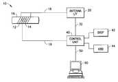
- FIG. 1is a schematic diagram of a remotely testable PIT tag interrogation system in accordance with the present invention
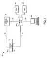
- FIG. 2is a schematic diagram of the antenna interface unit component of the present invention.
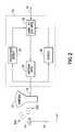
- FIG. 3is a schematic representation of the control unit component of the present invention.
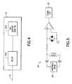
- FIG. 4is a schematic diagram of the remotely controlled test tag of the present invention.
- FIG. 5is a schematic circuit diagram of a preferred cross-over detector circuit deployed in the system of the present invention.
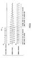
- FIG. 6is an illustration of exemplary signal waveforms obtained during certain diagnostic tests conducted within the system of the present invention.
- Control unit 40is generally connected to a general purpose digital computer 60 , such as an IBM compatible personal computer, a mini computer or other device capable of running software programs having functionality of the type further discussed herein.
- Control unit 40controls the major functions of the system 10 and maybe operated via a directly connected keyboard 44 and display 42 , providing direct operator control without the need for computer 60 .
- Antenna 12is deployed proximate a tunnel or passage 16 through which the tagged items to be tracked must pass.
- Antenna 12is powered by antenna interface 20 under the control of control unit 40 and generates an electromagnetic energy field within passage 16 .
- the PIT tagis energized by the electromagnetic field and in turn emits an identifying signal which is detected by antenna 12 and sent through antenna interface 20 to control unit 40 in a manner discussed further below. While the tunnel or passage 16 is depicted as a generally tubular passage in FIG.
- passage 16may vary in countless ways depending on the application to which the system is applied.
- passage 16is developed in such a manner as to cause the item carrying a PIT tag to pass within the electromagnetic field of antenna 12 in such a manner as to be energized by said electromagnetic field and to emit a signal responsive thereto, the requirements of the inventive system have been met.
- antenna 12is depicted as an antenna coil surrounding passage 16 , it will further be recognized by the person of skill in the art that antenna 12 may be configured and deployed in numerous ways such as, by way of none limiting example, flat panel antennas, arrays, antenna rods, dishes, etc. As discussed above in connection with passage 16 , antenna 12 need only be configured and deployed in such a manner as to generate an electromagnetic field of sufficient strength and dimension to energize a PIT tag in a desired location and to detect the signal generated by that PIT tag in response to energization by the antenna. In a preferred embodiment, the antenna is designed for the purpose of reading 134 Kilohertz (kHz) PIT tags conforming to the ISO/DIS 11785 standard. It will of course be recognized by the person of skill that the antenna and PIT tags may be designed to operate at other frequencies and energy levels than that of the preferred ISO standard, as a matter of engineering design choice.
- kHzKilohertz
- a remote test tag 14is mounted proximate said antenna 12 on said passage 16 .
- Remote test tag 14may be deployed within passage 16 , or placed external to passage 16 as a matter of design choice, provided that the test tag is fixedly mounted within the energizing field generated by antenna 12 for being energized by antenna 12 and for emitting an identifying signal to antenna 12 for processing by antenna interface unit 20 and subsequently by control unit 40 .
- remote test tag 14is mounted outside passage 16 so as to avoid interference with any items passing through channel 16 and also for the added benefit of providing an indication of the field strength of antenna 12 .
- remote test tag 14is positioned at the fringes of the radiated energy field, thus removing it from the location of maximum field strength of antenna 12 .
- antenna 12can successfully detect a signal generated by remote test tag 14 , this would generally indicate that the antenna is generating an adequate electromagnetic field within channel 16 , where the field strength is at its maximum, and also is sensitive enough to detect PIT tags within channel 16 .
- placement of the test tagmay vary depending on the field strength of the antenna
- Antenna 12is connected to antenna interface unit 20 via an antenna cable 18 .
- Antenna cable 18may be any type of antenna cable known in the art, such as, for example, coaxial cable, twin lead, of other conductor.
- antenna 12comprises a coil of 16 gauge (AWG) copper wire having 16 gauge wire leads directly connected to antenna interface 20 .
- AMG16 gauge
- Such a coilis particularly advantageously deployed in applications where the antenna surrounds a passage 16 having a round, ovoid, rectangular or square cross section, such as those commonly used to direct the passage of tagged fish through the electromagnetic field of antenna 12 .
- the specific technique of connecting antenna 12 to antenna interface 20 through antenna cable 18is purely a matter of design choice well within the skill of the routineer in the art of such antennas.
- remote test tag 14is shown connected through a remote test tag cable 19 to,control unit 40 .
- Remote test tag 14is, in a presently preferred embodiment, a standard ISO type B tag comprising standard ISO type B tag circuitry 104 .
- Test tag 14is, however, modified to include a remotely controllable relay 102 which may be selectively activated and deactivated by control unit 40 through a remote test tag cable 19 .
- control unit 40either at specifically programmed intervals or under direct user instruction, activates relay 102 in such a manner as to activate tag circuitry 104 on demand.
- electromagnetic field produced by antenna 12will energize test tag 14 in a manner known in the art.
- Test tag 14will, correspondingly, in a manner also known in the art, emit its test tag identification signal.
- control unit 40remotely activates remote test tag 14 and in turn receives through antenna 12 and antenna interface unit 20 the test tag identification signal emitted by test tag 14 , the integrity of the system has been confirmed and control unit 40 will signal to an operator that the system has successfully been tested. Operator indication may be accomplished through an indication on display 42 , or through a signal sent through data communications cable 50 to computer 60 .
- control unit 40may be accomplished in numerous ways other than through a direct wire and relay arrangement, as long as control unit 40 has the ability to selectively activate and deactivate tag circuitry 104 at predetermined times selected by the operator of the system 10 .
- the relayis operated for 50 to 60 milliseconds, which permits ample time for the tag to emit its identification signal while allowing for the reaction time of the relay.
- Different relays and tags, and different operating frequencies,will of course necessitate different activation times, as a matter of design choice.
- Antenna interface unit 20is a bi-directional subsystem which provides power at a predetermined antenna frequency to antenna 12 via an antenna drive unit 24 which is connected to antenna 12 through antenna cable 18 .
- Antenna interface unit 20communicates with control unit 40 via a communications interface unit 22 over control communication cable 32 .
- Communication interface unit 22is a bi-directional communications device conforming to EIA standard 485 .
- Interface unit 22manages the receipt of digital control signals from control unit 40 via communication control cable 32 and also manages the transmission of tag identification signals received by antenna 12 back to control unit 40 .
- Antenna drive unit 24contains power transistors and MOSFET circuitry known in the art for powering antenna 12 which generates the electromagnetic excitation field within which PIT tags will pass.
- the particular circuitry of communication interface unit 22 and antenna drive 24is of a type commonly known in the art and will not be discussed in detail herein, it being well within the abilities of the person of skill in the art to design such systems.
- the communication control cable 32is a shielded cable containing four twisted pairs of low capacitance 24 AWG stranded conductors, having aluminum shielding, a capacitance of 12.5 picofarads (pf) per foot, and a nominal impedance of 100 ohms.
- pfpicofarads
- the particular methodology for the transmission and reception of bi-directional signals between antenna interface unit 20 and control unit 40is a matter of design choice, and can be implemented in any manner known in the art for exchanging analog and/or digital signals. It is, however, preferred that the communication interface and cable conform to the presently known EIA RS485 communication standard.
- communication interface 22receives a 134.2 kHz excitation signal from control unit 40 via communication cable 32 .
- This excitation signalis in turn fed to antenna drive unit 24 which powers antenna 12 and causes antenna 12 to generate an electromagnetic field having a frequency at or near the excitation frequency of 134.2 kHz, depending on such factors as antenna geometry and tuning, which are easily modified as needed by the on of skill.
- test tag 14is enabled by control unit 40
- test tag circuitry 104is charged by the electromagnetic field 200 emitted by antenna 12 and utilizes this charge to emit a tag identification signal 400 which is detected by antenna 12 .
- Antenna 12then passes the detected tag identification signal 400 to antenna interface unit 20 .
- Identification signal 400is preferably an analog signal generated, in a manner known in the art, in accordance with the ISO type B tag identification convention. It will of course be recognized, however, that the identification signal emitted by any PIT tag detected by the system, including remote test tag 14 , may be generated in any manner known in the art of passive integrated transponder signaling as a matter of design choice.
- identification signal 400is generated by modulating the excitation energy field 200 .
- the ISO requirementis to set the excitation field at a fixed frequency of 134.2 kHz.
- the type B tagreceives enough energy, it returns its identification signal at a rate of 4,194 bits per second by modulating the amplitude of the excitation field at a rate of 1 bit per 32 cycles of the excitation field.
- a bit 0is represented when the amplitude variation is done in the middle of a 32 cycle bit cell.
- a bit 1is represented when no transition occurs in the middle of the bit cell.
- a demodulator 28receives the modulated tag identification signal 400 from antenna 12 and demodulates it, thereby converting it into a. signal useable by control unit 40 .
- Demodulator 28contains a digitizer (not shown) of a type known in the art which digitizes the tag identification signal and passes it to communication interface 22 for further transmission to control unit 40 .
- Antenna interface unit 20further contains a crossover detection circuit 26 that is controllable by control unit 40 .
- the crossover detector 26permits the detection of the voltage signal present on antenna 12 when antenna 12 is driven by antenna drive unit 24 .
- control unit 40activates a switch (not shown) which causes the output of crossover detector 26 to be sent through communication interface 22 to control unit 40 rather than the output of demodulator 28 .
- the switch functionmay be implemented in firmware in communication interface 22 , or via relay arrangement, or other commonly known technique, as a matter of design choice. Therefore, while the antenna is being driven, it is possible to know if a field is actually being produced by the antenna. This feature allows a system operator to detect an open antenna coil or a failure in the antenna drive system.
- a presently preferred crossover detection circuit schematicis depicted in FIG. 5, and exemplary output waveforms are depicted in FIG. 6 .
- FIG. 6there are depicted three exemplary waveforms representing, from top to bottom, an excitation drive signal 90 at 134.2 kHz, the corresponding antenna voltage signal 92 generated by said antenna when driven at that frequency, and an antenna crossover signal 96 emitted by said crossover detector 26 when detecting the antenna voltage signal.
- the set of signals to the left of, dashed line 500shows that crossover detector circuit 26 will output a square wave 96 having leading and trailing edges corresponding to the zero crossing points of the sinusoidal antenna voltage signal 92 present on antenna 12 as it is being driven by antenna drive circuit 24 in response to an applied square wave drive signal 90 at the preferred system design frequency of 134.2 kHz.
- detection of the antenna voltagemay be implemented in a number of ways, as long as the detector emits a signal corresponding to the signal present on antenna 12 during operation from which amplitude and frequency may be derived.
- Control unit 40comprises a microprocessor 46 which is preferably a programmable microprocessor containing, in a manner known in the art, a CPU, memory and a programmable logic unit (not shown).
- Microprocessor 46may be controlled via keyboard 44 and may output information via visual display 42 which may be, for example, a backlit liquid crystal display (LCD) or other commonly known visual display device such as, for example, a standard LCD screen or CRT.
- Microprocessor 46is also capable of driving visual and audible indicators (not shown) in a manner known in the art.
- Microprocessor 46is connected to a mother board 48 via a microprocessor controller cable array 49 .
- Cable 49may comprise a series of EIA RS 232 serial cables, as well as direct wiring connections between the microprocessor 46 and other system components.
- Mother board 48 and microprocessor 46are powered by power unit 52 which converts standard 120 volt AC power to the various voltage requirements of the various system components in a manner known in the art.
- a battery backup unit 58may also be optionally included.
- Mother board 48provides a point for termination and distribution of the various communication cables used throughout the system.
- the twisted pair connection between control unit 40 and antenna interface 20 , the control wire leads 19 of remote test tag 14 , and the data communication cable 50 connecting the control unit to computer 60all route through mother board 40 .
- the particular wiring and communication schemes mentioned hereinare merely representative of the presently preferred embodiments, it being recognized by the person of skill in the art that the particular data communication methods and control wiring schemes may be adopted in any manner known in the art, provided that the herein described signals necessary to operate the system 10 are present.
- data communication cables 50may be RS 232 type DB25 cables, EIA 485 metallic cables, fiber optic cables, or any combination thereof.
- a wireless communication methodology, utilizing digital or analog radio signals, infrared signals, etc.may also be deployed, as a matter of design choice.
- control unit 40is connected to a general purpose digital computer 60 and communicates therewith for the purpose of receiving control information therefrom and for passing information such as received PIT tag ID's and diagnostic signals from control unit 40 .
- control unit 40may communicate via additional communication line 110 to, for example, an RS 232 device for communication with a remote maintenance computer of other control mechanism (not shown).
- the system 10 through control unit 40may also optionally control programmable logic control (PLC) devices through PLC lead 80 under the control of microprocessor 46 through mother board 48 .
- PLCprogrammable logic control
- the modular nature of the systemalso permits, if desired, a redundant configuration so that two sets of antenna interface units 20 , control units 40 , antennas 12 , and remote tags 14 may be deployed for a single passage 16 , controlled by one or more computers 60 .
- FIGS. 2, 5 and 6an additional diagnostic capability of the system is depicted and herein described. Specifically, it is possible to remotely test the tuning of antenna 12 utilizing crossover detector 26 under the control of control unit 40 and optionally under the remote control of computer 60 .
- FIG. 6there is depicted to the right of dash line 500 the respective excitation drive signal 90 analog antenna voltage signal 92 and antenna crossover signal 94 described above.
- the antennais forced to oscillate at the excitation frequency, which in the preferred embodiment is 134.2 kHz as per ISO requirements.
- the natural frequency of an antennais determined by the inductance of the antenna (L) and the total value of the tuning capacitors (C).
- the natural frequency of the antennashould be 134.2 kHz, the preferred driving frequency of the system.
- a system operatorcan determine the natural frequency of the antenna Specifically, the frequency of the zero crossing (crossover) signal 94 output by the antenna crossover detector 26 while the antenna voltage is decaying corresponds to the resonant frequency of the antenna
- proper tuning of the antenna 12may be determined remotely utilizing the above-described antenna tuning test.
- Such a testmay be activated under direct operator control by interaction with keyboard 44 connected to control unit 40 or, alternatively, may be implemented under the control of computer 60 , as a matter of design choice.
- keyboard 44connected to control unit 40
- control unit 40may be implemented under the control of computer 60 , as a matter of design choice.
- feedback techniquesknown in the art, it is possible to remotely tune the antenna using this frequency information.
- the system in accordance with the present inventionoffers significant advantages over prior art systems in its ability to perform various functions from control points not local to the antenna sub-systems, which are typically field located and difficult to reach.
- the above-described diagnosticsmay be preprogrammed into computer 60 and/or control unit 40 for regular and systematic testing of the entire system without specific user intervention. Further, reprogramming, maintenance and functional changes may also be made from local or remote computer locations. Thus, changing operating parameters and performing preliminary troubleshooting from a central point is an inherent feature of the inventive system. Overall maintenance costs can be greatly reduced, since it will only be necessary to dispatch maintenance personnel to remote locations after verification that the equipment has actually malfunctioned, through the diagnostic tests described above.
Landscapes
- Engineering & Computer Science (AREA)
- Physics & Mathematics (AREA)
- Health & Medical Sciences (AREA)
- Computer Vision & Pattern Recognition (AREA)
- General Physics & Mathematics (AREA)
- Theoretical Computer Science (AREA)
- Artificial Intelligence (AREA)
- Toxicology (AREA)
- Biomedical Technology (AREA)
- Electromagnetism (AREA)
- General Health & Medical Sciences (AREA)
- Near-Field Transmission Systems (AREA)
- Radar Systems Or Details Thereof (AREA)
Abstract
Description

Claims (16)
Priority Applications (1)
| Application Number | Priority Date | Filing Date | Title |
|---|---|---|---|
| US09/619,853US6369694B1 (en) | 1997-08-26 | 2000-07-20 | Apparatus and method for remotely testing a passive integrated transponder tag interrogation system |
Applications Claiming Priority (2)
| Application Number | Priority Date | Filing Date | Title |
|---|---|---|---|
| US08/918,482US6184777B1 (en) | 1997-08-26 | 1997-08-26 | Apparatus and method for remotely testing a passive integrated transponder tag interrogation system |
| US09/619,853US6369694B1 (en) | 1997-08-26 | 2000-07-20 | Apparatus and method for remotely testing a passive integrated transponder tag interrogation system |
Related Parent Applications (1)
| Application Number | Title | Priority Date | Filing Date |
|---|---|---|---|
| US08/918,482ContinuationUS6184777B1 (en) | 1997-08-26 | 1997-08-26 | Apparatus and method for remotely testing a passive integrated transponder tag interrogation system |
Publications (1)
| Publication Number | Publication Date |
|---|---|
| US6369694B1true US6369694B1 (en) | 2002-04-09 |
Family
ID=25440455
Family Applications (2)
| Application Number | Title | Priority Date | Filing Date |
|---|---|---|---|
| US08/918,482Expired - LifetimeUS6184777B1 (en) | 1997-08-26 | 1997-08-26 | Apparatus and method for remotely testing a passive integrated transponder tag interrogation system |
| US09/619,853Expired - LifetimeUS6369694B1 (en) | 1997-08-26 | 2000-07-20 | Apparatus and method for remotely testing a passive integrated transponder tag interrogation system |
Family Applications Before (1)
| Application Number | Title | Priority Date | Filing Date |
|---|---|---|---|
| US08/918,482Expired - LifetimeUS6184777B1 (en) | 1997-08-26 | 1997-08-26 | Apparatus and method for remotely testing a passive integrated transponder tag interrogation system |
Country Status (1)
| Country | Link |
|---|---|
| US (2) | US6184777B1 (en) |
Cited By (27)
| Publication number | Priority date | Publication date | Assignee | Title |
|---|---|---|---|---|
| US20040056760A1 (en)* | 2002-09-13 | 2004-03-25 | Shinichiro Fukuoka | Radio IC tag reader, radio IC tag read apparatus and radio IC tag read system |
| US20040087314A1 (en)* | 2002-11-06 | 2004-05-06 | Charles Duncan | Apparatus and method for tracking the location and position of an individual |
| US20040087295A1 (en)* | 2002-11-05 | 2004-05-06 | Aamir Abbasi | Apparatus and method for antenna attachment |
| US6737973B2 (en)* | 2001-10-15 | 2004-05-18 | 3M Innovative Properties Company | Amplifier modulation |
| US20040132461A1 (en)* | 2002-11-06 | 2004-07-08 | Charles Duncan | Apparatus and method for tracking the location and position of an individual using an accelerometer |
| US20060065198A1 (en)* | 2004-08-16 | 2006-03-30 | Meads Roger W | Devices for improved milking |
| WO2006096623A3 (en)* | 2005-03-07 | 2006-11-09 | Sensormatic Electronics Corp | Automated tuning method for rfid labels |
| US7151442B1 (en)* | 2004-06-03 | 2006-12-19 | National Semiconductor Corporation | System, apparatus, and method for testing identification tags |
| US20070239282A1 (en)* | 2006-04-07 | 2007-10-11 | Caylor Edward J Iii | System and method for transmitting orthopaedic implant data |
| US20070270660A1 (en)* | 2006-03-29 | 2007-11-22 | Caylor Edward J Iii | System and method for determining a location of an orthopaedic medical device |
| EP1863123A1 (en)* | 2006-05-31 | 2007-12-05 | Harman/Becker Automotive Systems GmbH | Method for recognizing antenna types |
| US20080071146A1 (en)* | 2006-09-11 | 2008-03-20 | Caylor Edward J | System and method for monitoring orthopaedic implant data |
| US20080312511A1 (en)* | 2007-06-14 | 2008-12-18 | Alberta Research Council Inc. | Animal health monitoring system and method |
| US20080319512A1 (en)* | 2005-06-30 | 2008-12-25 | Jason Sherman | Apparatus, System, and Method for Transcutaneously Transferring Energy |
| US20090005876A1 (en)* | 2007-06-29 | 2009-01-01 | Dietz Terry L | Tibial tray assembly having a wireless communication device |
| US20100152562A1 (en)* | 2005-02-08 | 2010-06-17 | Abbott Diabetes Care Inc. | RF Tag on Test Strips, Test Strip Vials and Boxes |
| US20100152621A1 (en)* | 2007-02-23 | 2010-06-17 | Smith & Nephew, Inc. | Processing sensed accelerometer data for determination of bone healing |
| US20100234923A1 (en)* | 2005-06-30 | 2010-09-16 | Depuy Products, Inc. | Apparatus, system, and method for transcutaneously transferring energy |
| US20110205083A1 (en)* | 2007-09-06 | 2011-08-25 | Smith & Nephew, Inc. | System and method for communicating with a telemetric implant |
| US8015024B2 (en) | 2006-04-07 | 2011-09-06 | Depuy Products, Inc. | System and method for managing patient-related data |
| US8321302B2 (en) | 2002-01-23 | 2012-11-27 | Sensormatic Electronics, LLC | Inventory management system |
| US8388553B2 (en) | 2004-11-04 | 2013-03-05 | Smith & Nephew, Inc. | Cycle and load measurement device |
| US8486070B2 (en) | 2005-08-23 | 2013-07-16 | Smith & Nephew, Inc. | Telemetric orthopaedic implant |
| US8730044B2 (en) | 2002-01-09 | 2014-05-20 | Tyco Fire & Security Gmbh | Method of assigning and deducing the location of articles detected by multiple RFID antennae |
| US9918742B2 (en) | 2011-05-16 | 2018-03-20 | Smith & Nephew, Inc. | Measuring skeletal distraction |
| WO2018134425A1 (en)* | 2017-01-23 | 2018-07-26 | Loke Retail Technology A/S | System tester for an electronic anti-theft system |
| WO2023180852A1 (en)* | 2022-03-21 | 2023-09-28 | Wiliot, LTD. | Wireless tag testing |
Families Citing this family (21)
| Publication number | Priority date | Publication date | Assignee | Title |
|---|---|---|---|---|
| JP2001036545A (en)* | 1999-05-17 | 2001-02-09 | Sony Corp | Information processing unit, its method, information processing system and medium |
| US6714121B1 (en)* | 1999-08-09 | 2004-03-30 | Micron Technology, Inc. | RFID material tracking method and apparatus |
| US6720930B2 (en)* | 2001-01-16 | 2004-04-13 | Digital Angel Corporation | Omnidirectional RFID antenna |
| US7135978B2 (en)* | 2001-09-14 | 2006-11-14 | Calypso Medical Technologies, Inc. | Miniature resonating marker assembly |
| US6833790B2 (en) | 2002-04-12 | 2004-12-21 | Digital Angel Corporation | Livestock chute scanner |
| US6700547B2 (en) | 2002-04-12 | 2004-03-02 | Digital Angel Corporation | Multidirectional walkthrough antenna |
| US6900731B2 (en)* | 2002-10-30 | 2005-05-31 | Bellsouth Intellectual Property Corporation | Method for monitoring and tracking objects |
| US7274295B2 (en) | 2002-10-30 | 2007-09-25 | At&T Bls Intellectual Property, Inc. | Instantaneous mobile access to all pertinent life events |
| US20040084525A1 (en)* | 2002-10-30 | 2004-05-06 | Barrett Kreiner | System for monitoring and tracking objects |
| US7158032B2 (en)* | 2004-05-20 | 2007-01-02 | Xerox Corporation | Diagnosis of programmable modules |
| US7102517B2 (en)* | 2004-08-20 | 2006-09-05 | International Business Machines Corporation | Test fixture for evaluating RF identification system and related methods |
| US20060079187A1 (en)* | 2004-10-03 | 2006-04-13 | Struck James T | GPS, infrasonics, audio tools armband for location and assistance in response to astronomical and other crises |
| US7477152B2 (en)* | 2005-03-14 | 2009-01-13 | Avery Dennison Corporation | RFID application test systems and methods |
| DE102005027687A1 (en)* | 2005-06-15 | 2006-12-28 | Siemens Ag | Conveyor system, in particular airport baggage conveyor system |
| EP2091006A4 (en)* | 2006-11-30 | 2013-03-06 | Fujitsu Ltd | TEST EQUIPMENT, TEST METHOD, AND MANUFACTURING METHOD |
| US8973584B2 (en)* | 2009-02-13 | 2015-03-10 | Health Beacons, Inc. | Method and apparatus for locating passive integrated transponder tags |
| US8939153B1 (en) | 2013-03-15 | 2015-01-27 | Health Beacons, Inc. | Transponder strings |
| WO2016032910A1 (en) | 2014-08-24 | 2016-03-03 | Health Beacons, Inc. | Probe for determining magnetic marker locations |
| US11176435B2 (en)* | 2019-02-05 | 2021-11-16 | Wiliot Ltd. | System and method for testing energy harvesting internet of things (IoT) tags |
| US11880734B2 (en) | 2022-05-31 | 2024-01-23 | Wiliot, LTD. | Wireless tag testing |
| CN119253229B (en)* | 2024-10-12 | 2025-06-24 | 西安苏试广博环境可靠性实验室有限公司 | Automatic tuning transmitting antenna and method for RS103 test |
Citations (4)
| Publication number | Priority date | Publication date | Assignee | Title |
|---|---|---|---|---|
| US4646082A (en) | 1984-09-14 | 1987-02-24 | Motorola, Inc. | Inbound acknowledgement stack |
| US4663625A (en) | 1983-11-30 | 1987-05-05 | Motion Magnetics Inc. | Passive tag identification system and method |
| US5235326A (en) | 1991-08-15 | 1993-08-10 | Avid Corporation | Multi-mode identification system |
| US5523750A (en) | 1994-09-30 | 1996-06-04 | Palomar Technologies Corporation | Transponder system for communicating through an RF barrier |
Family Cites Families (1)
| Publication number | Priority date | Publication date | Assignee | Title |
|---|---|---|---|---|
| GB9202830D0 (en)* | 1992-02-11 | 1992-03-25 | Westinghouse Brake & Signal | A railway signalling system |
- 1997
- 1997-08-26USUS08/918,482patent/US6184777B1/ennot_activeExpired - Lifetime
- 2000
- 2000-07-20USUS09/619,853patent/US6369694B1/ennot_activeExpired - Lifetime
Patent Citations (4)
| Publication number | Priority date | Publication date | Assignee | Title |
|---|---|---|---|---|
| US4663625A (en) | 1983-11-30 | 1987-05-05 | Motion Magnetics Inc. | Passive tag identification system and method |
| US4646082A (en) | 1984-09-14 | 1987-02-24 | Motorola, Inc. | Inbound acknowledgement stack |
| US5235326A (en) | 1991-08-15 | 1993-08-10 | Avid Corporation | Multi-mode identification system |
| US5523750A (en) | 1994-09-30 | 1996-06-04 | Palomar Technologies Corporation | Transponder system for communicating through an RF barrier |
Cited By (50)
| Publication number | Priority date | Publication date | Assignee | Title |
|---|---|---|---|---|
| US6737973B2 (en)* | 2001-10-15 | 2004-05-18 | 3M Innovative Properties Company | Amplifier modulation |
| US20040183591A1 (en)* | 2001-10-15 | 2004-09-23 | 3M Innovative Properties Company | Amplifier modulation |
| US6909326B2 (en) | 2001-10-15 | 2005-06-21 | 3M Innovative Properties Comapny | Amplifier modulation |
| US8730044B2 (en) | 2002-01-09 | 2014-05-20 | Tyco Fire & Security Gmbh | Method of assigning and deducing the location of articles detected by multiple RFID antennae |
| US8321302B2 (en) | 2002-01-23 | 2012-11-27 | Sensormatic Electronics, LLC | Inventory management system |
| US20040056760A1 (en)* | 2002-09-13 | 2004-03-25 | Shinichiro Fukuoka | Radio IC tag reader, radio IC tag read apparatus and radio IC tag read system |
| US7176802B2 (en) | 2002-09-13 | 2007-02-13 | Omron Corporation | Radio IC tag reader, radio IC tag read apparatus and radio IC tag read system |
| US20040087295A1 (en)* | 2002-11-05 | 2004-05-06 | Aamir Abbasi | Apparatus and method for antenna attachment |
| US7242917B2 (en)* | 2002-11-05 | 2007-07-10 | Motorola Inc. | Apparatus and method for antenna attachment |
| US20040132461A1 (en)* | 2002-11-06 | 2004-07-08 | Charles Duncan | Apparatus and method for tracking the location and position of an individual using an accelerometer |
| US7110777B2 (en) | 2002-11-06 | 2006-09-19 | Charles Duncan | Apparatus and method for tracking the location and position of an individual using an accelerometer |
| US20040087314A1 (en)* | 2002-11-06 | 2004-05-06 | Charles Duncan | Apparatus and method for tracking the location and position of an individual |
| US7151442B1 (en)* | 2004-06-03 | 2006-12-19 | National Semiconductor Corporation | System, apparatus, and method for testing identification tags |
| US20060065198A1 (en)* | 2004-08-16 | 2006-03-30 | Meads Roger W | Devices for improved milking |
| US7284498B2 (en) | 2004-08-16 | 2007-10-23 | Meads Roger W | Devices for improved milking |
| US8388553B2 (en) | 2004-11-04 | 2013-03-05 | Smith & Nephew, Inc. | Cycle and load measurement device |
| US8358210B2 (en) | 2005-02-08 | 2013-01-22 | Abbott Diabetes Care Inc. | RF tag on test strips, test strip vials and boxes |
| US8390455B2 (en) | 2005-02-08 | 2013-03-05 | Abbott Diabetes Care Inc. | RF tag on test strips, test strip vials and boxes |
| US20100152562A1 (en)* | 2005-02-08 | 2010-06-17 | Abbott Diabetes Care Inc. | RF Tag on Test Strips, Test Strip Vials and Boxes |
| US8223021B2 (en) | 2005-02-08 | 2012-07-17 | Abbott Diabetes Care Inc. | RF tag on test strips, test strip vials and boxes |
| US8115635B2 (en) | 2005-02-08 | 2012-02-14 | Abbott Diabetes Care Inc. | RF tag on test strips, test strip vials and boxes |
| US8542122B2 (en) | 2005-02-08 | 2013-09-24 | Abbott Diabetes Care Inc. | Glucose measurement device and methods using RFID |
| WO2006096623A3 (en)* | 2005-03-07 | 2006-11-09 | Sensormatic Electronics Corp | Automated tuning method for rfid labels |
| US8092412B2 (en) | 2005-06-30 | 2012-01-10 | Depuy Products, Inc. | Apparatus, system, and method for transcutaneously transferring energy |
| US20080319512A1 (en)* | 2005-06-30 | 2008-12-25 | Jason Sherman | Apparatus, System, and Method for Transcutaneously Transferring Energy |
| US8244368B2 (en) | 2005-06-30 | 2012-08-14 | Depuy Products, Inc. | Apparatus, system, and method for transcutaneously transferring energy |
| US20100234923A1 (en)* | 2005-06-30 | 2010-09-16 | Depuy Products, Inc. | Apparatus, system, and method for transcutaneously transferring energy |
| US20100241040A1 (en)* | 2005-06-30 | 2010-09-23 | Depuy Products, Inc. | Apparatus, system, and method for transcutaneously transferring energy |
| US8187213B2 (en) | 2005-06-30 | 2012-05-29 | Depuy Products, Inc. | Apparatus, system, and method for transcutaneously transferring energy |
| US8721643B2 (en) | 2005-08-23 | 2014-05-13 | Smith & Nephew, Inc. | Telemetric orthopaedic implant |
| US8486070B2 (en) | 2005-08-23 | 2013-07-16 | Smith & Nephew, Inc. | Telemetric orthopaedic implant |
| US20070270660A1 (en)* | 2006-03-29 | 2007-11-22 | Caylor Edward J Iii | System and method for determining a location of an orthopaedic medical device |
| US8075627B2 (en) | 2006-04-07 | 2011-12-13 | Depuy Products, Inc. | System and method for transmitting orthopaedic implant data |
| US8015024B2 (en) | 2006-04-07 | 2011-09-06 | Depuy Products, Inc. | System and method for managing patient-related data |
| US8668742B2 (en) | 2006-04-07 | 2014-03-11 | DePuy Synthes Products, LLC | System and method for transmitting orthopaedic implant data |
| US10172551B2 (en) | 2006-04-07 | 2019-01-08 | DePuy Synthes Products, Inc. | System and method for transmitting orthopaedic implant data |
| US20070239282A1 (en)* | 2006-04-07 | 2007-10-11 | Caylor Edward J Iii | System and method for transmitting orthopaedic implant data |
| EP1863123A1 (en)* | 2006-05-31 | 2007-12-05 | Harman/Becker Automotive Systems GmbH | Method for recognizing antenna types |
| US8632464B2 (en) | 2006-09-11 | 2014-01-21 | DePuy Synthes Products, LLC | System and method for monitoring orthopaedic implant data |
| US20080071146A1 (en)* | 2006-09-11 | 2008-03-20 | Caylor Edward J | System and method for monitoring orthopaedic implant data |
| US20100152621A1 (en)* | 2007-02-23 | 2010-06-17 | Smith & Nephew, Inc. | Processing sensed accelerometer data for determination of bone healing |
| US9445720B2 (en) | 2007-02-23 | 2016-09-20 | Smith & Nephew, Inc. | Processing sensed accelerometer data for determination of bone healing |
| US20080312511A1 (en)* | 2007-06-14 | 2008-12-18 | Alberta Research Council Inc. | Animal health monitoring system and method |
| US8080064B2 (en) | 2007-06-29 | 2011-12-20 | Depuy Products, Inc. | Tibial tray assembly having a wireless communication device |
| US20090005876A1 (en)* | 2007-06-29 | 2009-01-01 | Dietz Terry L | Tibial tray assembly having a wireless communication device |
| US8570187B2 (en) | 2007-09-06 | 2013-10-29 | Smith & Nephew, Inc. | System and method for communicating with a telemetric implant |
| US20110205083A1 (en)* | 2007-09-06 | 2011-08-25 | Smith & Nephew, Inc. | System and method for communicating with a telemetric implant |
| US9918742B2 (en) | 2011-05-16 | 2018-03-20 | Smith & Nephew, Inc. | Measuring skeletal distraction |
| WO2018134425A1 (en)* | 2017-01-23 | 2018-07-26 | Loke Retail Technology A/S | System tester for an electronic anti-theft system |
| WO2023180852A1 (en)* | 2022-03-21 | 2023-09-28 | Wiliot, LTD. | Wireless tag testing |
Also Published As
| Publication number | Publication date |
|---|---|
| US6184777B1 (en) | 2001-02-06 |
Similar Documents
| Publication | Publication Date | Title |
|---|---|---|
| US6369694B1 (en) | Apparatus and method for remotely testing a passive integrated transponder tag interrogation system | |
| US6219543B1 (en) | Energy detection device | |
| US5012236A (en) | Electromagnetic energy transmission and detection apparatus | |
| EP2377076B1 (en) | Method and system for item level uhf rfid tag with low frequency power assist | |
| AU2001237177B2 (en) | A tag evaluation module for radio frequency identification (rfid) systems | |
| US5748085A (en) | Electronic article surveillance event monitoring system | |
| US8659428B2 (en) | Method and system for reducing effect of interference in integrated metal detection/electronic article surveillance systems | |
| EP1316814A1 (en) | Tracing of transponder-tagged objects | |
| JPH11512202A (en) | Multi-bit electronic article surveillance marker activated by an 8 MHz band interrogation signal | |
| EP1468409B1 (en) | Method and apparatus for monitoring fire detectors | |
| AU588957B2 (en) | Inventory control system | |
| WO2004027689A2 (en) | A data input device | |
| GB2149623A (en) | Identification device | |
| US9898906B2 (en) | RFID based event sensor | |
| AU699484B2 (en) | Electronic identification system | |
| GB2187916A (en) | Transponder presence indicator | |
| EP2036000B1 (en) | A method and system for reading a transponder | |
| GB2223380A (en) | Personnel location system | |
| US5160915A (en) | Wireless bistatic link intrusion detection system | |
| WO1995026790A1 (en) | Electronic toy or game playing apparatus | |
| KR101024608B1 (en) | Alarm generating device using electronic tag | |
| CN114023029A (en) | Anti-theft monitoring device and method for commodities in box | |
| CN208278196U (en) | A kind of RFID security identifying system that AGV trolley uses | |
| US6105860A (en) | Information storage device, scanner and information storage and reproducing apparatus | |
| CN214225929U (en) | Detection system for dismounting state of grounding wire |
Legal Events
| Date | Code | Title | Description |
|---|---|---|---|
| STCF | Information on status: patent grant | Free format text:PATENTED CASE | |
| AS | Assignment | Owner name:WELLS FARGO BUSINESS CREDIT, INC., MINNESOTA Free format text:SECURITY INTEREST;ASSIGNOR:DIGITAL ANGEL CORPORATION;REEL/FRAME:014007/0558 Effective date:20021030 | |
| AS | Assignment | Owner name:DIGITAL ANGEL CORPORATION, MINNESOTA Free format text:DISCHARGE OF RECORDED SECURITY INTEREST (ORIGINAL SECURITY AGREEMENT RECORDED ON APRIL 28, 2003 AT REEL 014007, FRAME 0558.);ASSIGNOR:WELLS FARGO BUSINESS CREDIT, INC.;REEL/FRAME:014683/0986 Effective date:20031104 | |
| FPAY | Fee payment | Year of fee payment:4 | |
| AS | Assignment | Owner name:DIGITAL ANGEL CORPORATION, MINNESOTA Free format text:ASSIGNMENT OF ASSIGNORS INTEREST;ASSIGNOR:MEJIA, E. ZEKE;REEL/FRAME:019920/0442 Effective date:20071004 | |
| AS | Assignment | Owner name:KALLINA CORPORATION, NEW YORK Free format text:INTELLECTUAL PROPERTY SECURITY AGREEMENT;ASSIGNORS:DIGITAL ANGEL CORPORATION;DIGITAL ANGEL TECHNOLOGY CORPORATION;FEARING MANUFACTURING CO., INC.;REEL/FRAME:020092/0815 Effective date:20070831 | |
| AS | Assignment | Owner name:DESTRON FEARING CORPORATION, MINNESOTA Free format text:CHANGE OF NAME;ASSIGNOR:DIGITAL ANGEL CORPORATION;REEL/FRAME:021348/0436 Effective date:20080506 | |
| FPAY | Fee payment | Year of fee payment:8 | |
| AS | Assignment | Owner name:TCI BUSINESS CAPITAL, INC., MINNESOTA Free format text:SECURITY AGREEMENT;ASSIGNORS:DESTRON FEARING CORPORATION;DIGITAL ANGEL CORPORATION;DIGITAL ANGEL TECHNOLOGY CORPORATION;AND OTHERS;REEL/FRAME:024933/0139 Effective date:20100831 | |
| AS | Assignment | Owner name:DIGITAL ANGEL TECHNOLOGY CORPORATION, MINNESOTA Free format text:RELEASE BY SECURED PARTY;ASSIGNOR:TCI BUSINESS CAPITAL, INC.;REEL/FRAME:026648/0034 Effective date:20110725 Owner name:DIGITAL ANGEL CORPORATION, FLORIDA Free format text:RELEASE BY SECURED PARTY;ASSIGNOR:TCI BUSINESS CAPITAL, INC.;REEL/FRAME:026648/0034 Effective date:20110725 Owner name:GT ACQUISITION SUB, INC., MINNESOTA Free format text:RELEASE BY SECURED PARTY;ASSIGNOR:TCI BUSINESS CAPITAL, INC.;REEL/FRAME:026648/0034 Effective date:20110725 Owner name:FEARING MANUFACTURING CO., INC., MINNESOTA Free format text:RELEASE BY SECURED PARTY;ASSIGNOR:TCI BUSINESS CAPITAL, INC.;REEL/FRAME:026648/0034 Effective date:20110725 Owner name:DESTRON FEARING CORPORATION, MINNESOTA Free format text:RELEASE BY SECURED PARTY;ASSIGNOR:TCI BUSINESS CAPITAL, INC.;REEL/FRAME:026648/0034 Effective date:20110725 | |
| AS | Assignment | Owner name:MORGAN STANLEY SENIOR FUNDING, INC., AS COLLATERAL Free format text:FIRST LIEN SECURITY AGREEMENT;ASSIGNORS:ALLFLEX USA, INC.;DESTRON FEARING CORPORATION;REEL/FRAME:030825/0310 Effective date:20130717 | |
| AS | Assignment | Owner name:BANK OF AMERICA, N.A., AS COLLATERAL AGENT, TEXAS Free format text:SECOND LIEN SECURITY AGREEMENT;ASSIGNORS:ALLFLEX USA, INC.;DESTRON FEARING CORPORATION;REEL/FRAME:030833/0469 Effective date:20130717 | |
| FPAY | Fee payment | Year of fee payment:12 | |
| AS | Assignment | Owner name:GT ACQUISITION SUB, INC., MINNESOTA Free format text:RELEASE (REEL 030833 / FRAME 0469);ASSIGNOR:BANK OF AMERICA, N.A.;REEL/FRAME:048762/0555 Effective date:20190401 Owner name:DESTRON FEARING CORPORATION, TEXAS Free format text:RELEASE (REEL 030833 / FRAME 0469);ASSIGNOR:BANK OF AMERICA, N.A.;REEL/FRAME:048762/0555 Effective date:20190401 Owner name:DIGITAL ANGEL CORPORATION, MINNESOTA Free format text:RELEASE (REEL 030833 / FRAME 0469);ASSIGNOR:BANK OF AMERICA, N.A.;REEL/FRAME:048762/0555 Effective date:20190401 Owner name:ALLFLEX, USA, INC., TEXAS Free format text:RELEASE (REEL 030833 / FRAME 0469);ASSIGNOR:BANK OF AMERICA, N.A.;REEL/FRAME:048762/0555 Effective date:20190401 Owner name:ALLFLEX, USA, INC., TEXAS Free format text:RELEASE (REEL 030825 / FRAME 0310);ASSIGNOR:MORGAN STANLEY SENIOR FUNDING, INC.;REEL/FRAME:049126/0851 Effective date:20190401 Owner name:GT ACQUISITION SUB, INC., MINNESOTA Free format text:RELEASE (REEL 030825 / FRAME 0310);ASSIGNOR:MORGAN STANLEY SENIOR FUNDING, INC.;REEL/FRAME:049126/0851 Effective date:20190401 Owner name:DESTRON FEARING CORPORATION, TEXAS Free format text:RELEASE (REEL 030825 / FRAME 0310);ASSIGNOR:MORGAN STANLEY SENIOR FUNDING, INC.;REEL/FRAME:049126/0851 Effective date:20190401 Owner name:DIGITAL ANGEL CORPORATION, MINNESOTA Free format text:RELEASE (REEL 030825 / FRAME 0310);ASSIGNOR:MORGAN STANLEY SENIOR FUNDING, INC.;REEL/FRAME:049126/0851 Effective date:20190401 |