US6368225B1 - Axially collapsible driveshaft assembly and method of manufacturing same - Google Patents
Axially collapsible driveshaft assembly and method of manufacturing sameDownload PDFInfo
- Publication number
- US6368225B1 US6368225B1US09/476,472US47647299AUS6368225B1US 6368225 B1US6368225 B1US 6368225B1US 47647299 AUS47647299 AUS 47647299AUS 6368225 B1US6368225 B1US 6368225B1
- Authority
- US
- United States
- Prior art keywords
- driveshaft
- tube section
- end portion
- driveshaft tube
- wires
- Prior art date
- Legal status (The legal status is an assumption and is not a legal conclusion. Google has not performed a legal analysis and makes no representation as to the accuracy of the status listed.)
- Expired - Fee Related
Links
Images


Classifications
- F—MECHANICAL ENGINEERING; LIGHTING; HEATING; WEAPONS; BLASTING
- F16—ENGINEERING ELEMENTS AND UNITS; GENERAL MEASURES FOR PRODUCING AND MAINTAINING EFFECTIVE FUNCTIONING OF MACHINES OR INSTALLATIONS; THERMAL INSULATION IN GENERAL
- F16D—COUPLINGS FOR TRANSMITTING ROTATION; CLUTCHES; BRAKES
- F16D3/00—Yielding couplings, i.e. with means permitting movement between the connected parts during the drive
- F16D3/02—Yielding couplings, i.e. with means permitting movement between the connected parts during the drive adapted to specific functions
- F16D3/06—Yielding couplings, i.e. with means permitting movement between the connected parts during the drive adapted to specific functions specially adapted to allow axial displacement
- F—MECHANICAL ENGINEERING; LIGHTING; HEATING; WEAPONS; BLASTING
- F16—ENGINEERING ELEMENTS AND UNITS; GENERAL MEASURES FOR PRODUCING AND MAINTAINING EFFECTIVE FUNCTIONING OF MACHINES OR INSTALLATIONS; THERMAL INSULATION IN GENERAL
- F16C—SHAFTS; FLEXIBLE SHAFTS; ELEMENTS OR CRANKSHAFT MECHANISMS; ROTARY BODIES OTHER THAN GEARING ELEMENTS; BEARINGS
- F16C3/00—Shafts; Axles; Cranks; Eccentrics
- F16C3/02—Shafts; Axles
- F16C3/03—Shafts; Axles telescopic
- Y—GENERAL TAGGING OF NEW TECHNOLOGICAL DEVELOPMENTS; GENERAL TAGGING OF CROSS-SECTIONAL TECHNOLOGIES SPANNING OVER SEVERAL SECTIONS OF THE IPC; TECHNICAL SUBJECTS COVERED BY FORMER USPC CROSS-REFERENCE ART COLLECTIONS [XRACs] AND DIGESTS
- Y10—TECHNICAL SUBJECTS COVERED BY FORMER USPC
- Y10T—TECHNICAL SUBJECTS COVERED BY FORMER US CLASSIFICATION
- Y10T403/00—Joints and connections
- Y10T403/49—Member deformed in situ
- Y10T403/4933—Member deformed in situ by separate, deformable element
- Y—GENERAL TAGGING OF NEW TECHNOLOGICAL DEVELOPMENTS; GENERAL TAGGING OF CROSS-SECTIONAL TECHNOLOGIES SPANNING OVER SEVERAL SECTIONS OF THE IPC; TECHNICAL SUBJECTS COVERED BY FORMER USPC CROSS-REFERENCE ART COLLECTIONS [XRACs] AND DIGESTS
- Y10—TECHNICAL SUBJECTS COVERED BY FORMER USPC
- Y10T—TECHNICAL SUBJECTS COVERED BY FORMER US CLASSIFICATION
- Y10T403/00—Joints and connections
- Y10T403/70—Interfitted members
- Y10T403/7026—Longitudinally splined or fluted rod
- Y10T403/7035—Specific angle or shape of rib, key, groove, or shoulder
Definitions
- This inventionrelates in general to drive train systems for transferring rotational power from a source of rotational power to a rotatably driven mechanism.
- this inventionrelates to an improved driveshaft assembly for use in such a drive train system that is axially collapsible in the event of a collision to absorb energy and a method for manufacturing same.
- Torque transmitting shaftsare widely used for transferring rotational power from a source of rotational power to a rotatably driven mechanism.
- a drive train systemis provided for transmitting rotational power from an output shaft of an engine/transmission assembly to an input shaft of an axle assembly so as to rotatably drive the wheels of the vehicle.
- a typical vehicular drive train systemincludes a hollow cylindrical driveshaft tube.
- a first universal jointis connected between the output shaft of the engine/transmission assembly and a first end of the driveshaft tube, while a second universal joint is connected between a second end of the driveshaft tube and the input shaft of the axle assembly.
- the universal jointsprovide a rotational driving connection from the output shaft of the engine/transmission assembly through the driveshaft tube to the input shaft of the axle assembly, while accommodating a limited amount of misalignment between the rotational axes of these three shafts.
- the driveshaft tubemay be formed as an assembly of first and second driveshaft sections that are connected together for concurrent rotational movement during normal operation, yet are capable of moving axially relative to one another when a relatively large axially compressive force is applied thereto, such as can occur during a collision.
- a variety of such axially collapsible driveshaft assembliesare known in the art.
- This inventionrelates to an improved structure for a driveshaft assembly for use in a drive train system that is relatively simple and inexpensive to perform.
- An inner driveshaft tube sectionis provided including an end portion having an outer surface.
- an outer driveshaft tube sectionis provided including an end portion having an inner surface.
- a plurality of axially extending wiresis positioned on either the outer surface of the inner driveshaft tube section or on the inner surface of the outer driveshaft tube section. Then, the end portion of the outer driveshaft tube section is disposed about the end portion of the inner driveshaft tube section so as to define an overlapped region therebetween. At least one of the end portions of the inner and outer driveshaft tube sections is then deformed so as to compress the wires therebetween.
- recessesare formed in the outer surface of the inner driveshaft tube section and in the inner surface of the outer driveshaft tube section.
- the wirescooperate with the recesses to prevent relative axial and rotational movement between the inner driveshaft tube section and the outer driveshaft tube section during normal operating conditions.
- the inner driveshaft tube sectionwill move axially within the outer driveshaft tube section, thereby collapsing and absorbing energy.
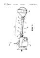
- FIG. 1is a side elevational view of a vehicle drive train system including an axially collapsible driveshaft assembly in accordance with the invention.
- FIG. 2is a perspective view, partially broken away, of a portion of the axially collapsible driveshaft assembly illustrated in FIG. 1 .
- FIG. 3is a sectional elevational view of the axially collapsible driveshaft assembly taken along line 3 — 3 of FIG. 2 .
- FIG. 4is an enlarged sectional elevational view of a portion of the of the axially collapsible driveshaft assembly illustrated in FIG. 3 .
- FIG. 5is a perspective view of an end of a first driveshaft tube section having a plurality of wires disposed thereabout with a first embodiment of a wire retainer.
- FIG. 6is a top plan view of a portion of the first embodiment of the wire retainer illustrated in FIG. 5 .
- FIG. 7is a end elevational view of a portion of the first embodiment of the wire retainer illustrated in FIGS. 5 and 6.
- FIG. 8is a top plan view of a portion of a second embodiment of the wire retainer.
- FIG. 9is a sectional elevational view showing the components of the axially collapsible driveshaft assembly in an initial state of assembly.
- FIG. 10is a sectional elevational view showing the components of the axially collapsible driveshaft assembly in an intermediate state of assembly.
- FIG. 11is a sectional elevational view showing the components of the axially collapsible driveshaft assembly in a final state of assembly.
- the drive train system 10includes a transmission 12 including an output shaft (not shown) that is connected to an input shaft (not shown) of an axle assembly 14 through a driveshaft assembly 16 .
- the driveshaft assembly 16includes a collapsible driveshaft, indicated generally at 18 , in accordance with this invention.
- the transmission output shaft and the axle assembly input shaftare not co-axially aligned. Therefore, universal joints 20 are provided at front and rear ends 22 of the driveshaft 18 to rotatably connect the driveshaft 18 at an angle to the output shaft of the transmission 12 and the input shaft of the axle assembly 14 .
- the connections between the ends 22 of the driveshaft 18 and the universal joints 20are usually accomplished by end fittings 24 attached to the ends 22 of the driveshaft 18 , such as tube yokes or slip yokes.
- the collapsible driveshaft 18 of this inventionis an assembly including an inner driveshaft tube section 26 and an outer driveshaft tube section 28 .
- both the inner driveshaft tube section 26 and the outer driveshaft tube section 28are elongated and cylindrical in shape.
- the inner driveshaft tube section 26includes an end portion 30 having an outer surface 32 .
- the outer driveshaft tube section 28includes an end portion 34 having an inner surface 36 .
- the inner driveshaft tube section 26 and the outer driveshaft tube section 28can be formed from any suitable materials.
- both the inner driveshaft tube section 26 and the outer driveshaft tube section 28are formed from aluminum alloy or steel. However, other materials, such as fiber reinforced composites or other combinations of metallic or non-metallic materials, can also be used. Suitable methods for forming the inner driveshaft tube section 26 and the outer driveshaft tube section 28 are well known to persons skilled in the art.
- the end portion 30 of the inner driveshaft tube section 26is received within the end portion 34 of the outer driveshaft tube section 28 in an overlapping or telescoping manner.
- the end portion 34 of the outer driveshaft tube section 28is disposed about the end portion 30 of the inner driveshaft tube section 26 so as to define an overlapped region 38 .
- the overlapped region 38can have any length L that is suitable for providing the collapsible driveshaft 18 with acceptable torque transmitting properties and collapsing properties.
- the overlapped region 38has a length L in the range of from about one and one-half inches to about ten inches, and more preferably from about one and one-half inches to about four and one-half inches.
- At least one wire 40is disposed between the outer surface 32 of the end portion 30 of the inner driveshaft tube section 26 and the inner surface 36 of the end portion 34 of the outer driveshaft tube section 28 .
- the wires 40are, in the preferred embodiment, relatively small solid cylindrical members that extend throughout at least some, but preferably all, of the overlapped region 38 .
- the term “wire”can refer to a member having any desired shape or size.
- the wires 40are aligned axially with the inner and outer driveshaft tube sections 26 and 28 , respectively.
- the wires 40need not extend axially with the inner driveshaft tube section 26 and the outer driveshaft tube section 28 . As best shown in FIG. 4, the wires 40 are received in recesses 42 and 44 respectively formed in the outer surface 32 of the end portion 30 of the inner driveshaft tube section 26 and in the inner surface 36 of the end portion 34 of the outer driveshaft tube section 28 .
- the wires 40cooperate with the recesses 42 and 44 to prevent relative axial and rotational movement between the inner driveshaft tube section 26 and the outer driveshaft tube section 28 during normal operating conditions of the collapsible driveshaft 18 .
- the inner driveshaft tube section 26will move axially within the outer driveshaft tube section 28 , thereby collapsing and absorbing energy.
- Such relative axial movementis accomplished by deformation of either or both of the inner driveshaft tube section 26 and the outer driveshaft tube section 28 .
- the outer surface 32 of the inner driveshaft tube section 26 and the inner surface 36 of the outer driveshaft tube section 28are both deformed at the axial ends of the recesses 42 and 44 during such relative axial movement of the inner and outer driveshaft tube sections 26 and 28 , respectively.
- the wires 40can be formed having any desired shape and size.
- the wires 40can preferably have a diameter within the range of from about 0.02 inch to about 0.09 inch, and more preferably from about 0.04 inch to about 0.06 inch.
- the number of wires 40 disposed about the overlapped region 38is within the range of from about eight to about ninety, and more preferably from about thirty to about fifty.
- the inner driveshaft tube section 26can be formed having an outer diameter of about four inches, and the collapsible driveshaft 18 includes about forty of the wires 40 equally spaced around the overlapped region 38 .
- the wires 40can be formed from any material suitable to normally prevent relative axial and rotational movement between the inner driveshaft tube section 26 and the outer driveshaft tube section 28 during normal operating conditions of the collapsible driveshaft 18 .
- the wires 40are formed from a hard metallic material, such as annealed stainless steel. If the wires 40 are formed from a different metal than one or both of the inner driveshaft tube section 26 and the outer driveshaft tube section 28 , the wires 40 are preferably provided with a coating of an inert protective material, such as an organic material, to prevent galvanic corrosion of the metals used to form the inner driveshaft tube section 26 and the outer driveshaft tube section 28 .
- the collapsible driveshaft 18can be manufactured by any suitable method.
- FIGS. 5 through 11illustrate a preferred method for manufacturing the collapsible driveshaft 18 illustrated in FIGS. 1 through 4.
- a plurality of the axially extending wires 40is initially disposed about the outer surface 32 of the end portion 30 of the inner driveshaft tube section 26 .
- the plurality of the axially extending wires 40may be disposed about the inner surface 36 of the end portion 34 of the outer driveshaft tube section 28 .
- the wires 40can be manually positioned on the outer surface 32 of the inner driveshaft tube section 26 and retained thereon by any suitable means, such as adhesive or tape.
- the wires 40be supported on a wire retainer, a first embodiment of which is illustrated at 50 in FIGS. 5, 6 , and 7 .
- the wire retainer 50can be formed as a flat strip of material having a plurality of slots 52 formed therethrough. The slots 52 are sized to frictionally engage the ends of the wires 40 so as to support a plurality of such wires 40 thereon for ease of handling.
- the wire retainer 50 and wires 40can then be wrapped about the end portion 30 of the inner driveshaft tube section 26 as shown in FIG. 5 to position the wires 40 thereabout.
- An alternative embodiment of a wire retainer 54is illustrated in FIG. 8 .
- the wire retainer 54can be formed as a strip of material having a plurality of openings 56 formed therein.
- the openings 56are sized to frictionally engage the ends of the wires 40 so as to support a plurality of such wires 40 thereon for ease of handling.
- the wire retainer 54can then be wrapped about the end portion 30 of the inner driveshaft tube section 26 as shown in FIG. 5 to position the wires 40 thereabout.
- the wire retainers 50 and 54may be formed having an annular shape that corresponds in size with the outer diameter of the end portion 30 of the inner driveshaft tube section 26 .
- the annular wire retainers 50 and 54can then be quickly disposed about the end portion 30 of the inner driveshaft tube section 26 .
- the end portion 34 of the outer driveshaft tube section 28is disposed thereabout so as to define the overlapped region 38 .
- the inner surface 36 of the end portion 34 of the outer driveshaft tube section 28is preferably formed to be at least slightly larger in diameter than an outer diameter defined by the outer surfaces of the wires 40 positioned on the outer surface 32 of the end portion 30 of the inner driveshaft tube section 26 . This allows the end portion 34 of the outer driveshaft tube section 28 to be moved quickly and easily about the end portion 30 of the inner driveshaft tube section 26 without disturbing the wires 40 positioned thereon. As a result, a relatively small circumferential space is provided between the outer surfaces of the wires 40 and the inner surface 36 of the end portion 34 of the outer driveshaft tube section 28 , as shown in FIG. 10 .
- the end portion 34 of the outer driveshaft tube section 28is then deformed inwardly into engagement with the wires 40 and the end portion 30 of the inner driveshaft tube section 26 .
- the end portion 30 of the inner driveshaft tube section 26can be deformed outwardly into engagement with the end portion 34 of the outer driveshaft tube section 28 .
- the end portion 34 of the outer driveshaft tube section 28can be deformed inwardly simultaneously as the end portion 30 of the inner driveshaft tube section 26 is deformed outwardly. In each instance, such deformation compresses the wires 40 between the inner surface 36 of the end portion 34 of the outer driveshaft tube section 28 and the outer surface 32 of the end portion 30 of the inner driveshaft tube section 26 .
- the wires 40(which are relatively incompressible) cause the recesses 42 and 44 described above to be formed in the inner surface 36 of the end portion 34 of the outer driveshaft tube section 28 and in the outer surface 32 of the end portion 30 of the inner driveshaft tube section 26 .
- This deformationcan be accomplished by any suitable forming method, such as swaging, forming with a forming die, or magnetic pulse forming. Preferred methods involve compressing the end portion 30 of the outer driveshaft tube section 28 inwardly while supporting an inner surface 48 of the inner driveshaft tube section 26 with a mandrel (not shown).
- swagingis rotary swaging, which employs a die which rotates around the overlapped region 38 of the driveshaft 18 while it alternately rapidly collapses and expands in the radial direction, much like a hammer, to compress the outer driveshaft tube section 28 about the inner driveshaft tube section 26 .
- One type of forming dieis a reducing die, in which the die has a tapered opening, and the driveshaft 18 is pushed into the opening to compress the driveshaft 18 at the overlapped region 38 .
- an annular electromagnetic inductor coilis disposed about the overlapped region 38 of the driveshaft 18 and energized to generate a magnetic field for collapsing the end portion 34 of the outer driveshaft tube section 28 onto the end portion 30 of the inner driveshaft tube section 26 .
- the forming methodinvolves compressing the outer driveshaft tube section 28 radially inwardly about the wires 40 and the inner driveshaft tube section 26 in the overlapped region 38 .
- a mandrel(not shown) can be disposed inside the inner driveshaft tube section 26 to support the inner surface 48 of the inner driveshaft tube section 26 .
- Compression of the outer driveshaft tube section 28 about the wires 40causes the formation of indents or recesses 42 and 44 in the outer surface 32 of the inner driveshaft tube section 26 and the inner surface 36 of the outer driveshaft tube section 28 , respectively.
- Deformation of the inner and outer driveshaft tube sections 26 and 28 about the wires 40allows the driveshaft 18 to transmit torque during operation of the vehicle.
- the inner and outer driveshaft tube sections 26 and 28are pressed together about the wires 40 to form an interference fit between the outer surface 32 of the inner driveshaft tube section 26 and the inner surface 36 of the outer driveshaft tube section 34 .
- Such an interference fitallows the driveshaft 18 to transmit additional torque.
- the end portion 34 of the outer driveshaft tube section 28is initially disposed about the end portion 30 of the inner driveshaft tube section 26 so as to define the overlapped region 38 .
- the inner driveshaft tube section 26is formed to be somewhat smaller in diameter than the outer driveshaft tube section 28 so that an annular space is provided between the overlapping end portions 30 and 34 , respectively.
- the plurality of wires 40can be inserted within the annular space.
- an automated mechanism(not shown) is provided for inserting the wires 40 within this annular space.
- either or both of the end portion 30 of the inner driveshaft tube section 26 and the end portion 34 of the outer driveshaft tube section 28are deformed about the wires 40 in the manner described above.
- the wires 40 and the recesses 42 and 44cooperate to form a mechanical interlock between the inner driveshaft tube section 26 and the outer driveshaft tube section 28 that prevents relative axial and rotational movement therebetween during normal operating conditions.
- the inner and outer driveshaft tube sections 26 and 28will deform and move axially relative to one another, thereby collapsing and absorbing energy.
- the axial collapse force of the driveshaft 18is desirable to keep the axial collapse force of the driveshaft 18 as low as possible, i.e. at a value which is greater than the axial forces applied during normal vehicle operation plus an amount provided as a safety margin.
- the known collapsible driveshaft tube designs having swaged or bumped regionsrequire axial forces ranging from about 27,000 pounds to about 37,000 pounds to collapse.
- the axial forces required to collapse the collapsible driveshaft 18 of this inventioncan be about one-half to about one-third of the prior art values, or about 10,000 pounds to about 20,000 pounds.
- the collapsible driveshaft 18 of this inventionwill collapse under lower axial forces, thereby absorbing these axial forces and better protecting the occupants of the vehicle.
- the collapsible driveshaft 18 of the inventiontakes advantage of the low axial force associated with a splined connection while avoiding the high cost. It uses splines formed with wires 40 instead of more expensive machined or formed splines.
- the inner and outer driveshaft tube sections 26 and 28are commercially available without requiring costly forming or machining operations. Axial collapse force and torque capacity can be altered by changing the diameter of the wires 40 , the number of wires 40 , and the length of the wires 40 . Consequently, this design can be tuned to fit the vehicle's axial collapse force and torque capacity requirements.
Landscapes
- Engineering & Computer Science (AREA)
- General Engineering & Computer Science (AREA)
- Mechanical Engineering (AREA)
- Ocean & Marine Engineering (AREA)
- Shafts, Cranks, Connecting Bars, And Related Bearings (AREA)
Abstract
Description
Claims (19)
Priority Applications (4)
| Application Number | Priority Date | Filing Date | Title |
|---|---|---|---|
| US09/476,472US6368225B1 (en) | 1999-12-30 | 1999-12-30 | Axially collapsible driveshaft assembly and method of manufacturing same |
| BR0006285-5ABR0006285A (en) | 1999-12-30 | 2000-12-27 | Axially telescopic drive shaft assembly and method of manufacturing it |
| GB0031714AGB2357822B (en) | 1999-12-30 | 2000-12-27 | Driveshaft assembly and method of manufacturing same |
| DE10065707ADE10065707A1 (en) | 1999-12-30 | 2000-12-29 | Axially collapsible drive shaft assembly and method of making the same |
Applications Claiming Priority (1)
| Application Number | Priority Date | Filing Date | Title |
|---|---|---|---|
| US09/476,472US6368225B1 (en) | 1999-12-30 | 1999-12-30 | Axially collapsible driveshaft assembly and method of manufacturing same |
Publications (1)
| Publication Number | Publication Date |
|---|---|
| US6368225B1true US6368225B1 (en) | 2002-04-09 |
Family
ID=23891988
Family Applications (1)
| Application Number | Title | Priority Date | Filing Date |
|---|---|---|---|
| US09/476,472Expired - Fee RelatedUS6368225B1 (en) | 1999-12-30 | 1999-12-30 | Axially collapsible driveshaft assembly and method of manufacturing same |
Country Status (4)
| Country | Link |
|---|---|
| US (1) | US6368225B1 (en) |
| BR (1) | BR0006285A (en) |
| DE (1) | DE10065707A1 (en) |
| GB (1) | GB2357822B (en) |
Cited By (19)
| Publication number | Priority date | Publication date | Assignee | Title |
|---|---|---|---|---|
| US6543266B1 (en)* | 1999-08-24 | 2003-04-08 | Magna International Inc. | Hydroformed collapsible driveshaft and steering shaft and methods of making the same |
| US20030114231A1 (en)* | 2001-12-14 | 2003-06-19 | Visteon Global Technologies, Inc. | Integrally stiffened composite drive shaft |
| US6620050B2 (en)* | 2001-10-30 | 2003-09-16 | Mando Corporation | Universal joint |
| US20030213117A1 (en)* | 2002-04-04 | 2003-11-20 | Silva Jose Da | Method of manufacturing an axially collapsible driveshaft assembly |
| US6663057B2 (en)* | 2002-03-18 | 2003-12-16 | Garelick Mfg. Co. | Adjustable pedestal for boat accessory |
| US6840128B1 (en)* | 1999-08-26 | 2005-01-11 | Toyota Jidosha Kabushiki Kaisha | Energy absorbing type steering device, and method and device for assembling the steering device |
| US20060035714A1 (en)* | 2004-08-13 | 2006-02-16 | Yi Qu | Collapsible vehicle driveshaft |
| US20060156776A1 (en)* | 2004-12-27 | 2006-07-20 | Yablochnikov Boris A | Method and apparatus for performing a magnetic pulse forming process |
| US20090324323A1 (en)* | 2006-07-18 | 2009-12-31 | Mitsubishi Heavy Industries, Ltd. | Hydraulic detachable coupling |
| DE112007003403T5 (en) | 2007-04-04 | 2010-02-18 | GKN Driveline North America, Inc., Auburn Hills | Lubricant cover of a constant velocity universal joint with increased torsional compliance |
| US9028164B2 (en) | 2012-03-08 | 2015-05-12 | Dana Automotive Systems Group, Llc | Magnetic pulse formed vehicle driveshaft and method of making same |
| US9890808B2 (en) | 2015-04-22 | 2018-02-13 | American Axle & Manufacturing, Inc. | Telescoping propshaft |
| US9937968B2 (en) | 2015-07-13 | 2018-04-10 | Michael Goren | Stackable vehicle |
| US10202141B2 (en) | 2015-07-13 | 2019-02-12 | Hurdler Motors | Vehicle, vehicle drive assembly and vehicle steering assembly |
| US20200375361A1 (en)* | 2019-05-28 | 2020-12-03 | Brunswick Corporation | Vertically adjustable pedestal for boat accessory |
| US20210207667A1 (en)* | 2018-05-14 | 2021-07-08 | Sew-Eurodrive Gmbh & Co. Kg | Brake assembly for an electric motor |
| US11493091B2 (en) | 2017-08-25 | 2022-11-08 | Dana Automotive Systems, Group, Llc | Propeller shaft crash collapse assembly |
| US11614199B2 (en) | 2019-05-28 | 2023-03-28 | Brunswick Corporation | Vertically adjustable pedestal for boat accessory |
| US20240159244A1 (en)* | 2022-11-16 | 2024-05-16 | Emerson Climate Technologies, Inc. | Foil bearing and driveshaft assemblies and compressor including same |
Families Citing this family (1)
| Publication number | Priority date | Publication date | Assignee | Title |
|---|---|---|---|---|
| DE102008015028A1 (en)* | 2008-03-19 | 2009-09-24 | Rauschnabel, Eberhard, Dr. | Massive hollow shafts e.g. drive shaft, connecting method, involves sliding connecting piece over profiled inner part, and completely or partially molding outer part in profile inner part by profiled tool or flexible reduction tool |
Citations (17)
| Publication number | Priority date | Publication date | Assignee | Title |
|---|---|---|---|---|
| US845156A (en)* | 1906-08-18 | 1907-02-26 | Fred F Winchester | Staple or fastener. |
| US1220483A (en) | 1913-11-22 | 1917-03-27 | Homer D Williams | Expansion-coupling. |
| US2089168A (en)* | 1934-10-12 | 1937-08-03 | Perry W Brown | Spline connection |
| US2217188A (en) | 1940-02-03 | 1940-10-08 | Snyder Gerson | Radio antenna |
| US2344425A (en) | 1942-08-26 | 1944-03-14 | Snyder Mfg Company | Radio antenna |
| GB649440A (en)* | 1948-12-03 | 1951-01-24 | Singer Motors Ltd | Method of and means for securing an internally splined collar upon a splined shaft |
| US2992548A (en) | 1959-03-28 | 1961-07-18 | Jean Walterscheid Maschinenfab | Universal-joint shaft assembly |
| US3112627A (en)* | 1959-11-13 | 1963-12-03 | Leitz Ernst Gmbh | Cylindrical mount for photographic objectives |
| US3358520A (en)* | 1964-12-24 | 1967-12-19 | Heinkel Ag Ernst | Adjustable sheave |
| US4008845A (en)* | 1973-07-16 | 1977-02-22 | Richard Bleckmann | Method of positive and non-positive cold-joining |
| US4535645A (en) | 1983-03-24 | 1985-08-20 | The Torrington Company | Vehicle steering sub-assembly |
| US4807351A (en)* | 1988-02-18 | 1989-02-28 | Asea Composites, Inc. | Method for attaching an end-fitting to a drive shaft tube |
| GB2208313A (en) | 1986-03-08 | 1989-03-22 | Brd Co Ltd | Propeller shaft for motor vehicle |
| US5477750A (en)* | 1993-05-03 | 1995-12-26 | The Torrington Company | Variable length shaft assembly |
| US5645366A (en)* | 1994-02-28 | 1997-07-08 | Unisia Jecs Corporation | Shaft coupling structure of drive shaft |
| JPH09267754A (en) | 1996-04-02 | 1997-10-14 | Koyo Seiko Co Ltd | Intermediate shaft of steering device |
| US5709605A (en) | 1996-12-23 | 1998-01-20 | General Motors Corporation | Shaft coupling |
Family Cites Families (3)
| Publication number | Priority date | Publication date | Assignee | Title |
|---|---|---|---|---|
| US3376060A (en)* | 1964-12-14 | 1968-04-02 | Shinko Wire Co Ltd | Metallic member and joint assembly |
| US4934042A (en)* | 1987-10-16 | 1990-06-19 | Bush Timothy J | Lamination to rotor shaft retention method utilizing spring pins |
| JPH0921407A (en)* | 1995-07-07 | 1997-01-21 | Nippondenso Co Ltd | Torque transmission mechanism and fuel injection device using it |
- 1999
- 1999-12-30USUS09/476,472patent/US6368225B1/ennot_activeExpired - Fee Related
- 2000
- 2000-12-27BRBR0006285-5Apatent/BR0006285A/enactiveSearch and Examination
- 2000-12-27GBGB0031714Apatent/GB2357822B/ennot_activeExpired - Fee Related
- 2000-12-29DEDE10065707Apatent/DE10065707A1/ennot_activeWithdrawn
Patent Citations (18)
| Publication number | Priority date | Publication date | Assignee | Title |
|---|---|---|---|---|
| US845156A (en)* | 1906-08-18 | 1907-02-26 | Fred F Winchester | Staple or fastener. |
| US1220483A (en) | 1913-11-22 | 1917-03-27 | Homer D Williams | Expansion-coupling. |
| US2089168A (en)* | 1934-10-12 | 1937-08-03 | Perry W Brown | Spline connection |
| US2217188A (en) | 1940-02-03 | 1940-10-08 | Snyder Gerson | Radio antenna |
| US2344425A (en) | 1942-08-26 | 1944-03-14 | Snyder Mfg Company | Radio antenna |
| GB649440A (en)* | 1948-12-03 | 1951-01-24 | Singer Motors Ltd | Method of and means for securing an internally splined collar upon a splined shaft |
| US2992548A (en) | 1959-03-28 | 1961-07-18 | Jean Walterscheid Maschinenfab | Universal-joint shaft assembly |
| US3112627A (en)* | 1959-11-13 | 1963-12-03 | Leitz Ernst Gmbh | Cylindrical mount for photographic objectives |
| US3358520A (en)* | 1964-12-24 | 1967-12-19 | Heinkel Ag Ernst | Adjustable sheave |
| US4008845A (en)* | 1973-07-16 | 1977-02-22 | Richard Bleckmann | Method of positive and non-positive cold-joining |
| US4535645A (en) | 1983-03-24 | 1985-08-20 | The Torrington Company | Vehicle steering sub-assembly |
| GB2208313A (en) | 1986-03-08 | 1989-03-22 | Brd Co Ltd | Propeller shaft for motor vehicle |
| US4807351A (en)* | 1988-02-18 | 1989-02-28 | Asea Composites, Inc. | Method for attaching an end-fitting to a drive shaft tube |
| US5477750A (en)* | 1993-05-03 | 1995-12-26 | The Torrington Company | Variable length shaft assembly |
| US5645366A (en)* | 1994-02-28 | 1997-07-08 | Unisia Jecs Corporation | Shaft coupling structure of drive shaft |
| US5674026A (en) | 1994-02-28 | 1997-10-07 | Unisia Jecs Corporation | Shaft coupling structure of drive shaft |
| JPH09267754A (en) | 1996-04-02 | 1997-10-14 | Koyo Seiko Co Ltd | Intermediate shaft of steering device |
| US5709605A (en) | 1996-12-23 | 1998-01-20 | General Motors Corporation | Shaft coupling |
Cited By (25)
| Publication number | Priority date | Publication date | Assignee | Title |
|---|---|---|---|---|
| US6543266B1 (en)* | 1999-08-24 | 2003-04-08 | Magna International Inc. | Hydroformed collapsible driveshaft and steering shaft and methods of making the same |
| US6840128B1 (en)* | 1999-08-26 | 2005-01-11 | Toyota Jidosha Kabushiki Kaisha | Energy absorbing type steering device, and method and device for assembling the steering device |
| US6620050B2 (en)* | 2001-10-30 | 2003-09-16 | Mando Corporation | Universal joint |
| US20030114231A1 (en)* | 2001-12-14 | 2003-06-19 | Visteon Global Technologies, Inc. | Integrally stiffened composite drive shaft |
| US6663057B2 (en)* | 2002-03-18 | 2003-12-16 | Garelick Mfg. Co. | Adjustable pedestal for boat accessory |
| US20030213117A1 (en)* | 2002-04-04 | 2003-11-20 | Silva Jose Da | Method of manufacturing an axially collapsible driveshaft assembly |
| US7080437B2 (en)* | 2002-04-04 | 2006-07-25 | Torque-Traction Technologies Llc | Method of manufacturing an axially collapsible driveshaft assembly |
| US20060035714A1 (en)* | 2004-08-13 | 2006-02-16 | Yi Qu | Collapsible vehicle driveshaft |
| US20060156776A1 (en)* | 2004-12-27 | 2006-07-20 | Yablochnikov Boris A | Method and apparatus for performing a magnetic pulse forming process |
| US20090324323A1 (en)* | 2006-07-18 | 2009-12-31 | Mitsubishi Heavy Industries, Ltd. | Hydraulic detachable coupling |
| US8360677B2 (en)* | 2006-07-18 | 2013-01-29 | Mitsubishi Heavy Industries, Ltd. | Hydraulic detachable coupling |
| DE112007003403T5 (en) | 2007-04-04 | 2010-02-18 | GKN Driveline North America, Inc., Auburn Hills | Lubricant cover of a constant velocity universal joint with increased torsional compliance |
| US9028164B2 (en) | 2012-03-08 | 2015-05-12 | Dana Automotive Systems Group, Llc | Magnetic pulse formed vehicle driveshaft and method of making same |
| US9890808B2 (en) | 2015-04-22 | 2018-02-13 | American Axle & Manufacturing, Inc. | Telescoping propshaft |
| US9937968B2 (en) | 2015-07-13 | 2018-04-10 | Michael Goren | Stackable vehicle |
| US10202141B2 (en) | 2015-07-13 | 2019-02-12 | Hurdler Motors | Vehicle, vehicle drive assembly and vehicle steering assembly |
| US10633016B2 (en) | 2015-07-13 | 2020-04-28 | Hurdler Motors, Inc. | Vehicle, vehicle drive assembly and vehicle steering assembly |
| US11493091B2 (en) | 2017-08-25 | 2022-11-08 | Dana Automotive Systems, Group, Llc | Propeller shaft crash collapse assembly |
| US20210207667A1 (en)* | 2018-05-14 | 2021-07-08 | Sew-Eurodrive Gmbh & Co. Kg | Brake assembly for an electric motor |
| US11988258B2 (en)* | 2018-05-14 | 2024-05-21 | Sew-Eurodrive Gmbh & Co. Kg | Brake assembly for an electric motor |
| US20200375361A1 (en)* | 2019-05-28 | 2020-12-03 | Brunswick Corporation | Vertically adjustable pedestal for boat accessory |
| US11028963B2 (en)* | 2019-05-28 | 2021-06-08 | Brunswick Corporation | Vertically adjustable pedestal for boat accessory |
| US11614199B2 (en) | 2019-05-28 | 2023-03-28 | Brunswick Corporation | Vertically adjustable pedestal for boat accessory |
| US20240159244A1 (en)* | 2022-11-16 | 2024-05-16 | Emerson Climate Technologies, Inc. | Foil bearing and driveshaft assemblies and compressor including same |
| US12031543B2 (en)* | 2022-11-16 | 2024-07-09 | Copeland Lp | Foil bearing and driveshaft assemblies and compressor including same |
Also Published As
| Publication number | Publication date |
|---|---|
| GB2357822A (en) | 2001-07-04 |
| DE10065707A1 (en) | 2001-07-05 |
| GB0031714D0 (en) | 2001-02-07 |
| GB2357822B (en) | 2004-02-11 |
| BR0006285A (en) | 2001-09-25 |
Similar Documents
| Publication | Publication Date | Title |
|---|---|---|
| US6368225B1 (en) | Axially collapsible driveshaft assembly and method of manufacturing same | |
| US6484384B1 (en) | Method of manufacturing an axially collapsible driveshaft assembly | |
| US6015350A (en) | Collapsible vehicle driveshaft | |
| US6761503B2 (en) | Splined member for use in a slip joint and method of manufacturing the same | |
| US6371859B1 (en) | Axially collapsible driveshaft assembly | |
| US6193612B1 (en) | Collapsible driveshaft | |
| US6572199B1 (en) | Flanged tubular axle shaft assembly | |
| EP1375943B1 (en) | Rolling ball slip joint formed from two tubular members | |
| US6257041B1 (en) | Method of forming a one-piece steering shaft member | |
| EP0122033A1 (en) | Composite shafts | |
| US6754943B1 (en) | Method of manufacturing an axially collapsible driveshaft assembly | |
| JP2003220846A (en) | Propeller shaft assembly | |
| EP1698787A2 (en) | Method of manufacturing an axially collapsible splined assembly | |
| US6634078B1 (en) | Method of manufacturing a splined member for use in a slip joint | |
| US6367680B1 (en) | Component for vehicular driveshaft assembly and method of manufacturing same | |
| US7181846B2 (en) | Method of manufacturing a combined driveshaft tube and yoke assembly | |
| US7080437B2 (en) | Method of manufacturing an axially collapsible driveshaft assembly | |
| US7080436B2 (en) | Method of manufacturing an axially collapsible driveshaft | |
| EP2272600A1 (en) | Method of manufacturing a splined member for use in a driveshaft assembly | |
| EP1683979A2 (en) | Method of manufacturing a combined driveshaft tube and yoke assembly | |
| US20050028341A1 (en) | Method of manufacturing a combined driveshaft tube and yoke assembly | |
| US5611135A (en) | Method of making a tube yoke for drive line assembly | |
| US8226490B2 (en) | Collapsible shaft assembly | |
| GB2371614A (en) | Method of manufacturing an axially collapsible driveshaft | |
| GB2172376A (en) | Propeller shaft joints |
Legal Events
| Date | Code | Title | Description |
|---|---|---|---|
| AS | Assignment | Owner name:DANA CORPORATION, OHIO Free format text:ASSIGNMENT OF ASSIGNORS INTEREST;ASSIGNORS:BREESE, DOUGLAS E.;DUGGAN, JAMES A.;REEL/FRAME:010594/0058 Effective date:20000223 | |
| AS | Assignment | Owner name:SPICER DRIVESHAFT, INC., OHIO Free format text:ASSIGNMENT OF ASSIGNORS INTEREST;ASSIGNOR:DANA CORPORATION, A VIRGINIA CORPORATION;REEL/FRAME:011667/0621 Effective date:20001221 | |
| AS | Assignment | Owner name:SPICER DRIVESHAFT, INC., OHIO Free format text:ASSIGNMENT OF ASSIGNORS INTEREST;ASSIGNOR:DANA CORPORATION;REEL/FRAME:011705/0638 Effective date:20010323 | |
| AS | Assignment | Owner name:TORQUE-TRACTION TECHNOLOGIES, INC., OHIO Free format text:CHANGE OF NAME;ASSIGNOR:SPICER DRIVESHAFT, INC.;REEL/FRAME:013933/0631 Effective date:20021231 | |
| FPAY | Fee payment | Year of fee payment:4 | |
| AS | Assignment | Owner name:TORQUE-TRACTION TECHNOLOGIES LLC,OHIO Free format text:MERGER;ASSIGNOR:TORQUE-TRACTION TECHNOLOGY, INC.;REEL/FRAME:017240/0259 Effective date:20060101 Owner name:TORQUE-TRACTION TECHNOLOGIES LLC, OHIO Free format text:MERGER;ASSIGNOR:TORQUE-TRACTION TECHNOLOGY, INC.;REEL/FRAME:017240/0259 Effective date:20060101 | |
| AS | Assignment | Owner name:DANA AUTOMOTIVE SYSTEMS GROUP, LLC, OHIO Free format text:ASSIGNMENT OF ASSIGNORS INTEREST;ASSIGNOR:TORQUE-TRACTION TECHNOLOGIES, LLC;REEL/FRAME:020518/0949 Effective date:20080131 Owner name:DANA AUTOMOTIVE SYSTEMS GROUP, LLC,OHIO Free format text:ASSIGNMENT OF ASSIGNORS INTEREST;ASSIGNOR:TORQUE-TRACTION TECHNOLOGIES, LLC;REEL/FRAME:020518/0949 Effective date:20080131 | |
| AS | Assignment | Owner name:CITICORP USA, INC., NEW YORK Free format text:INTELLECTUAL PROPERTY TERM FACILITY SECURITY AGREEMENT;ASSIGNORS:DANA HOLDING CORPORATION;DANA LIMITED;DANA AUTOMOTIVE SYSTEMS GROUP, LLC;AND OTHERS;REEL/FRAME:020859/0359 Effective date:20080131 Owner name:CITICORP USA, INC., NEW YORK Free format text:INTELLECTUAL PROPERTY REVOLVING FACILITY SECURITY AGREEMENT;ASSIGNORS:DANA HOLDING CORPORATION;DANA LIMITED;DANA AUTOMOTIVE SYSTEMS GROUP, LLC;AND OTHERS;REEL/FRAME:020859/0249 Effective date:20080131 Owner name:CITICORP USA, INC.,NEW YORK Free format text:INTELLECTUAL PROPERTY REVOLVING FACILITY SECURITY AGREEMENT;ASSIGNORS:DANA HOLDING CORPORATION;DANA LIMITED;DANA AUTOMOTIVE SYSTEMS GROUP, LLC;AND OTHERS;REEL/FRAME:020859/0249 Effective date:20080131 Owner name:CITICORP USA, INC.,NEW YORK Free format text:INTELLECTUAL PROPERTY TERM FACILITY SECURITY AGREEMENT;ASSIGNORS:DANA HOLDING CORPORATION;DANA LIMITED;DANA AUTOMOTIVE SYSTEMS GROUP, LLC;AND OTHERS;REEL/FRAME:020859/0359 Effective date:20080131 | |
| REMI | Maintenance fee reminder mailed | ||
| LAPS | Lapse for failure to pay maintenance fees | ||
| STCH | Information on status: patent discontinuation | Free format text:PATENT EXPIRED DUE TO NONPAYMENT OF MAINTENANCE FEES UNDER 37 CFR 1.362 | |
| FP | Lapsed due to failure to pay maintenance fee | Effective date:20100409 |