US6367902B1 - Effector platform for performing actions over vertical surfaces - Google Patents
Effector platform for performing actions over vertical surfacesDownload PDFInfo
- Publication number
- US6367902B1 US6367902B1US09/450,484US45048499AUS6367902B1US 6367902 B1US6367902 B1US 6367902B1US 45048499 AUS45048499 AUS 45048499AUS 6367902 B1US6367902 B1US 6367902B1
- Authority
- US
- United States
- Prior art keywords
- effector
- platform
- effector platform
- pen
- end effectors
- Prior art date
- Legal status (The legal status is an assumption and is not a legal conclusion. Google has not performed a legal analysis and makes no representation as to the accuracy of the status listed.)
- Expired - Lifetime
Links
Images


Classifications
- B—PERFORMING OPERATIONS; TRANSPORTING
- B43—WRITING OR DRAWING IMPLEMENTS; BUREAU ACCESSORIES
- B43L—ARTICLES FOR WRITING OR DRAWING UPON; WRITING OR DRAWING AIDS; ACCESSORIES FOR WRITING OR DRAWING
- B43L13/00—Drawing instruments, or writing or drawing appliances or accessories not otherwise provided for
- B43L13/10—Pantographic instruments for copying, enlarging, or diminishing
- B—PERFORMING OPERATIONS; TRANSPORTING
- B43—WRITING OR DRAWING IMPLEMENTS; BUREAU ACCESSORIES
- B43K—IMPLEMENTS FOR WRITING OR DRAWING
- B43K23/00—Holders or connectors for writing implements; Means for protecting the writing-points
- B43K23/02—Holders or connectors for writing implements; Means for protecting the writing-points with means for preventing rolling
- B—PERFORMING OPERATIONS; TRANSPORTING
- B43—WRITING OR DRAWING IMPLEMENTS; BUREAU ACCESSORIES
- B43L—ARTICLES FOR WRITING OR DRAWING UPON; WRITING OR DRAWING AIDS; ACCESSORIES FOR WRITING OR DRAWING
- B43L13/00—Drawing instruments, or writing or drawing appliances or accessories not otherwise provided for
- B43L13/02—Draughting machines or drawing devices for keeping parallelism
Definitions
- the present inventionrelates generally to performing mechanical actions such as printing, and more particularly to a platform for carrying end effectors for performing the mechanical actions on whiteboards and other substantially vertical surfaces.
- Image capture technologiesenable marks drawn on a surface to be captured in electronic form. These include the pressure-sensitive tablets such as the SMART Board from SMART Technologies, Inc. of Calgary, Alberta, Canada, location-sensitive surfaces accompanied by special pens such as the Liveboard from Xerox Corporation of Stamford, Conn., and Mimeo from Virtual Ink Corporation of Boston, Mass., Laser-based pen trackers such as the SoftBoard from Microfield Graphics, Inc. of Portland, Oreg., camera-based scanning such as the ZombieBoard from Xerox Corporation, and 1 -dimensional scan bars such as the Copyboard from Xerox Corporation.
- the ZombieBoardis further described in U.S. Pat. No. 5,528,290 to Saund, entitled DEVICE FOR TRANSCRIBING IMAGES ON A BOARD USING A CAMERA BASED BOARD SCANNER.
- Image display technologiespermit stored electronic images to be displayed on a large surface. These include plasma, active matrix, liquid crystal, light-emitting diode, and projectors which can be either front-projection or rear-projection. Of the various image display technologies, only the projectors are compatible with an inexpensive, passive, surface of variable and extensible size. All of the others require dedicated display hardware which is expensive and fixed in size.
- the present inventionis a platform, called an effector platform, for carrying and/or manipulating end effectors to perform various mechanical tasks.
- the effector platform of the present inventionis part of a Pendulum Whiteboard Printer System which is so named because the effector platform of the present invention is suspended against the force of gravity by suspension wires. It is not a true pendulum in the x-y plane because two wires are used.
- the present inventionprovides an inexpensive mechanism for remotely generating images on whiteboards and other substantially vertical surfaces.
- imagerefers to any marking created by a marking element such as a dry-erase pen.
- the markingsmay be in the form of textual characters, straight or curved strokes, or any other types of marks that could be hand-drawn.
- the effector platformis provided for holding an end effector such as the marking element.
- the effector platformis suspended by two wires from two spools placed near the upper, outer, boundaries of the surface to be marked on. The lengths of the two wires are adjusted to control the location of the effector platform over the surface to be marked on. These wires are typically wound on motorized spools permitting their lengths to be varied under computer control.
- the spoolsmay be located above and beyond the ends of the target surface so that all parts of the surface are reachable. If needed, control signals to the effector platform can be provided through the wires using techniques well-known in the art. Power may be supplied to the effector platform through the wires or from an on-board battery.
- FIG. 1is a block/perspective view diagram of a Pendulum Whiteboard Printer system according to the present invention.
- FIG. 2is a block diagram depicting the functional elements of an effector platform according to the present invention.
- FIG. 3is a perspective view diagram of an effector platform according to the present invention.
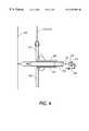
- FIG. 4is a side plan view of an effector platform according to the present invention.
- FIG. 5is a block diagram of a first alternative embodiment of the effector platform according to the present invention.
- FIG. 6is a detail view diagram of a part of the effector platform according to the present invention.
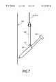
- FIG. 7is a side plan view diagram of a second alternate embodiment of the effector platform according to the present invention.
- FIG. 1depicts the Pendulum Whiteboard Printer system of which the present invention is a part.
- An end effector 130such as marking pen or the like is used for creating images on a whiteboard 105 .
- a dry-erase markerwill typically be used for whiteboards.
- the present inventionis not limited to marking on whiteboards, but may be used with any substantially-vertical surface, and that the action performed by the whiteboard printer is not limited to simply making marks, but may also be used for performing other actions, as is discussed in greater detail in concurrently filed, co-assigned, U.S. patent application Ser. No.
- the end effector, 130is held in place and moved with the effector platform 120 of the present invention.
- the effector platform 120is suspended from a left wire 114 and a right wire 112 .
- the left wire 114is connected to a left spool 108
- the right wire 112is connected to a right spool 110 .
- the left and right spoolsare equipped with motors (not shown) of types well-known in the art which control the reeling in and unreeling of wire from the spool.
- the motorsmay be stepper motors, or DC motors with shaft sensors or position sensors, or any other such mechanism capable of turning the spools in a controlled manner to reel in and unreel wire.
- stepper motorsor DC motors with shaft sensors or position sensors, or any other such mechanism capable of turning the spools in a controlled manner to reel in and unreel wire.
- the effector platformcan be returned to a parking facility 170 to keep pens from drying out, among other reasons.
- the parking facility 170is discussed in greater detail in concurrently filed, co-assigned, U.S. patent application Ser. No. 09/450, 466 entitled A PARKING MECHANISM FOR STORING AND EXCHANGING END EFFECTORS IN A SYSTEM FOR PERFORMING ACTIONS, which is hereby incorporated by reference into the present specification.
- the whiteboard printer 100will typically be controlled by a computer 102 , through a controller 104 , which may be implemented in hardware or software, and may be a separate unit or part of the computer 102 .
- the computer 102may be any general-purpose computer known in the art.
- the computer 102communicates with the whiteboard printer 100 through the controller 104 by way of an interface 103 , which may be any commonly-used computer communication interface such as a parallel or a serial interface. If closed-loop positioning is utilized, a camera 150 may be used to provide feedback information to the computer 102 , as depicted, or directly to the controller 104 .
- the calculations described below for positioning the effector platform 120may be performed by the computer 102 and/or the controller 104 and may be implemented in software and/or hardware.
- Driver programs 1023 for application programs 1022 for such applications as word processing, spreadsheets, and presentation graphics, among others,may be provided to generate their respective outputs on large vertical surfaces.
- the positioning of the effector platform 120may also be manually controlled using a joystick 106 connected to the controller 104 , as shown, or to the computer 102 . Signals from the computer 102 or joystick 106 are translated by the controller 104 and transmitted to the effector platform 120 , where they are decoded by the onboard control electronics 140 .
- the effector platform 120may be moved to any position beneath and between the left spool 108 and right spool 110 by adjusting the lengths of the left and right wires 114 and 112 , respectively.
- the left and right spools 108 and 110are preferably placed above the top edge of the whiteboard and beyond the left and right edges of the whiteboard, respectively, as shown in FIG. 1 .
- the positioning of the effector platform 120is described in greater detail, along with other aspects of the Pendulum Whiteboard Printer of which the effector platform is a part, in concurrently filed, co-assigned, U.S. patent application Serial No. 09/450, 468 entitled SYSTEM FOR EFFECTING ACTIONS OVER VERTICAL SURFACES, which is hereby incorporated by reference into the present specification.
- the effector platform 120 of the present inventionincludes an end effector 130 , a proximity sensor 210 , control electronics 220 , a mechanical actuator 230 , a power supply 240 , and a z-force generator 250 .
- the end effector 130is the element of the effector platform 120 that does the actual work.
- the end effectorwould be a dry-erase marker.
- Other examples of end effectorswill be discussed in greater detail below.
- the proximity sensor 210provides information on how close an end effector is to a surface. It can be practiced using any such proximity sensing mechanisms and techniques as are known and understood in the art. Examples include physical touch sensors as well as echo sensors which bounce light or sound from the surface an determine a return trip time for the echo.
- the actuator 230is operated to manipulate the end effector 130 , typically by moving the end effector toward and away from the whiteboard 105 or other substantially vertical surface.
- the on-board control electronics 140are provided to receive control signals from a computer or other external source and convert them into mechanical actions by the end effector 130 . These mechanical actions may be for performing any of a wide variety of tasks, as will be appreciated by those skilled in the art.
- the power supply 240supplies power to the control electronics 140 , the actuator 230 , and if necessary, to the end effector 130 itself.
- the power supply 240will be implemented as the left and right suspension wires, 114 and 112 , although the power supply 240 may also be a battery of any kind known in the art. Using a battery can be advantageous in not requiring power to be transmitted down the suspension wires, which will allow different materials to be used as the wire as well as reduce the signal noise on the those wires, assuming signals are also transmitted down the suspension wires.
- the z-force generator 250generates a force to push the effector platform 120 either toward or away from the whiteboard 105 or other substantially vertical surface.
- the effector platform 120may hang purely passively from the suspension wires while the end effector 130 operates on the surface or objects on it.
- the platformmust be actively driven closer to the surface.
- the platformmust hang at substantial distance from the board in order to clear these objects while navigating around the board.
- some active meansmust then be used to move the platform close enough to the surface for the effectors to operate.
- the z-force generator 250is used to meet those needs and may be implemented as a fan or propeller mounted on the platform, as shown in FIG. 3, to either blow the effector platform 120 toward the surface or suck it toward the surface. In other embodiments of the invention, electromagnetic attraction may be used. If the surface is metallic as is a conventional white-board, an electromagnet on the effector platform 120 can attract or hold the effector platform to the surface while the end effector 130 performs the mechanical do action.
- a marking pen 310such as a dry-erase marker is used as the primary end effector for creating marks.
- the mechanical actuator 230includes a sleeve 340 ; a servo motor 320 ; a mechanical linkage 330 ; and a mechanism for engaging and disengaging the marking pen 310 .
- a typical marking pen 310such as a dry-erase marker, is designed so that the cap (not shown) can be held at the end of the marking pen in a receptacle 311 with engaging ribs 313 .
- the effector cap 317which is connected to the mechanical linkage 330 is provided with an effector plug 319 configured to securely engage with the receptacle 311 .
- effector plug 319 and effector cap 317are constructed as a single unit, with the effector plug 319 being slightly smaller than the receptacle 311 , but being equipped with engaging arms 321 which may be extended to engage the inside wall of the receptacle 311 .
- the effector plug 319 and effector cap 317may be implemented as separate units, with the effector plug 319 being made to fit snugly in the receptacle 311 and not be removed except to replace pens which have dried out.
- Such an effector plugcould be constructed from a permanent magnet, and the effector cap 317 could then be implemented with an electromagnet.
- the actuatorcould engage and disengage with the marking pen 311 simply by turning the electromagnet on and off, or by reversing the polarity of the electromagnet.
- the sleeve 340 of the mechanical actuatoris for supporting the marking pen 310 . It can be a cylindrical tube, as shown, or may be a partial cylindrical tube or any other physical configuration that provides suitable support. It may be provided with a groove 345 to allow for greater protraction of the marking pen.
- the servo motor 320is configured to rotate a disk 325 connected to one end of a mechanical linkage 330 , the other end of which is connected to the marking pen 310 .
- the mechanical linkage 330is configured and coupled to the servo motor 320 and the marking pen 310 in such a way that when the servo motor 320 rotates the disk 325 , the mechanical linkage 330 pushes the marking pen 310 into the sleeve 340 or pulls it out from the sleeve, depending on the direction of rotation.
- the motor 320may be equipped with a resistance sensor to determine when the end effector has come into contact with the surface.
- FIG. 4depicts the pen 310 in a position retracted away from the surface 105 to enable the effector platform 120 to be moved to a desired location.
- the pen 310is then protracted, as depicted by the dashed outline, to touch the surface 105 at the desired target location(s) in order to create marks.
- FIG. 6depicts an alternative actuator 230 arrangement where, instead of a servo motor 320 indirectly moving the pen using a mechanical linkage 330 as in FIG. 3, a motor (not shown) rotates a small wheel 610 which protrudes through the sleeve 340 and contacts the pen 310 . As the wheel 610 rotates, the pen slides along the length of the sleeve 340 , thereby retracting or protracting the pen.
- FIG. 5a first alternative embodiment of the present invention is shown in which the effector platform 120 is provided with more than one end effector 510 , and a corresponding number of actuators 530 .
- This embodimentis probably most useful in drawing situations where multiple colors are desired.
- Those skilled in the artwill readily appreciate that the relative positions of the different end effectors 510 can be accounted for by simply updating the positioning calculations with an appropriate offset representing the horizontal distance between a desired end effector and some reference point such as a central end effector.
- the control electronics 520 , z-force generator 550 , and power supply 540may all be implemented in a similar manner as with the single end effector embodiment.
- FIG. 7a second alternative embodiment of the present invention is shown in which the effector platform 120 is implemented as a marking pen 130 attached to a pivot point 137 , and counterbalanced with a weight 135 that swings the pen toward the board.
- an ink/whiteout/cleaner sprayerwhere an ink nozzle is directed at the vertical surface to spray one or more colors of ink and/or whiteout from a small reservoir on the effector platform.
- a marking surfacesuch as a brush, roller, or the like, could be provided on the end effector, and the nozzle and or sprayer could be used to replenish ink, which may include dry-erase ink and other such materials, paint, or other liquid or semi-liquid material on the marking surface.
- a sprayercould be used for raster mode drawing, where the sprayer could be turned on and off rapidly. Additionally, the spray area could be adjusted by changing the proximity of the sprayer end effector to the surface;
- an eraserimplemented as a wand or block with a felt or other soft surface for erasing dry-erase markings on a whiteboard
- the effector platformwould in this case carry a small light emitter such as a laser pointer;
- a robotic gripperin which a general-purpose or specialized robotic gripper would be able to grab push-pins and the like in order to move or remove items from a pinboard such as a standard bulletin board;
- an electromagnetic transponderwhich could be useful where some objects on the surface may be designed to respond to radio-frequency signals.
- the effector platformwould in this case bring a transponder within range of individual objects;
- a vacuum gripperin which a suction device can grab at objects such as papers.
- a vacuum grippermay also be used to suck the platform firmly to the board;
- a quick-change end-effectorin which a rack of different end-effectors tools is provided, and a special receptacle on the robotic gripper grabs the appropriate end effector depending on the current task.
- the parking facility 170may be used in various ways beyond merely serving as a stopping place.
- the parking facilitymay be used to swap between various end effectors, or resupply ink, paint, whiteout, cleaning fluid, or other such liquid or semi-liquid material being applied to a substantially vertical surface.
- the parking platformcould serve as a recharging station.
Landscapes
- Drawing Aids And Blackboards (AREA)
- Facsimiles In General (AREA)
Abstract
Description
Claims (6)
Priority Applications (3)
| Application Number | Priority Date | Filing Date | Title |
|---|---|---|---|
| US09/450,484US6367902B1 (en) | 1999-11-29 | 1999-11-29 | Effector platform for performing actions over vertical surfaces |
| JP2000348628AJP4629855B2 (en) | 1999-11-29 | 2000-11-15 | Effector base that operates on a vertical surface |
| CA002326482ACA2326482C (en) | 1999-11-29 | 2000-11-22 | Effector platform for performing actions over vertical surfaces |
Applications Claiming Priority (1)
| Application Number | Priority Date | Filing Date | Title |
|---|---|---|---|
| US09/450,484US6367902B1 (en) | 1999-11-29 | 1999-11-29 | Effector platform for performing actions over vertical surfaces |
Publications (1)
| Publication Number | Publication Date |
|---|---|
| US6367902B1true US6367902B1 (en) | 2002-04-09 |
Family
ID=23788283
Family Applications (1)
| Application Number | Title | Priority Date | Filing Date |
|---|---|---|---|
| US09/450,484Expired - LifetimeUS6367902B1 (en) | 1999-11-29 | 1999-11-29 | Effector platform for performing actions over vertical surfaces |
Country Status (3)
| Country | Link |
|---|---|
| US (1) | US6367902B1 (en) |
| JP (1) | JP4629855B2 (en) |
| CA (1) | CA2326482C (en) |
Cited By (9)
| Publication number | Priority date | Publication date | Assignee | Title |
|---|---|---|---|---|
| US20020196482A1 (en)* | 2001-06-26 | 2002-12-26 | Hoberock Tim M. | Dry erase printer presentation board |
| US20040239640A1 (en)* | 2003-06-02 | 2004-12-02 | Lahade Sudhakar S. | Slidable electronic whiteboard system |
| CN101876875B (en)* | 2009-04-28 | 2012-05-30 | 太瀚科技股份有限公司 | Electronic whiteboard with partial printing function |
| WO2014167497A1 (en)* | 2013-04-08 | 2014-10-16 | Ratti Carlo Filippo | Vertical plotter |
| US20150072072A1 (en)* | 2010-11-22 | 2015-03-12 | Martin Chard | Marking Device and Method |
| WO2015153812A1 (en)* | 2014-04-02 | 2015-10-08 | President And Fellows Of Harvard College | Color- or grayscale-sensing, magnetic, mobile, marking robot |
| WO2017184478A1 (en)* | 2016-04-17 | 2017-10-26 | President And Fellows Of Harvard College | Magnetic receptive sensor and optimized drawing and erasing for vertically driving robot |
| US10086516B2 (en) | 2014-04-02 | 2018-10-02 | President And Fellows Of Harvard College | Color- or grayscale-sensing, magnetic, mobile, marking robot |
| CN112277505A (en)* | 2020-11-23 | 2021-01-29 | 广东赛晔信息技术有限公司 | an intelligent blackboard |
Citations (26)
| Publication number | Priority date | Publication date | Assignee | Title |
|---|---|---|---|---|
| US3665608A (en) | 1969-07-17 | 1972-05-30 | Digital Equipment Corp | Position-locating system |
| US4135245A (en) | 1977-01-04 | 1979-01-16 | Hewlett-Packard Company | Plotter with automatic pen-changer |
| US4288798A (en) | 1978-04-13 | 1981-09-08 | Goerz Electro Gesellschaft M.B.H. | Stylus changing device |
| EP0074190A2 (en) | 1981-08-25 | 1983-03-16 | Gould Bryans Instruments Limited | Writing device for plotting and recording apparatus |
| US4401996A (en) | 1980-09-01 | 1983-08-30 | Watanabe Sokki Kabushiki Kaisha | Apparatus for recording-pen interchange |
| US4412383A (en) | 1981-08-13 | 1983-11-01 | Benzion Landa | Cable driven plotter |
| US4496958A (en) | 1981-11-19 | 1985-01-29 | Koh-I-Noor Rapidograph, Inc. | Drawing pen exchanger for computer controlled drawing machines |
| US4501931A (en) | 1982-06-26 | 1985-02-26 | Fujitsu Limited | Color information input system for electronic blackboard |
| US4564078A (en) | 1983-01-18 | 1986-01-14 | Fujitsu Limited | Apparatus for storing felt pens for an electronic board |
| US4583292A (en) | 1984-08-10 | 1986-04-22 | Edwin Langberg | Low inertia X-Y cable drive |
| US4600083A (en) | 1984-09-06 | 1986-07-15 | Parent Christopher A | Positioning systems |
| US4628326A (en) | 1984-02-14 | 1986-12-09 | Iwatsu Electric Co., Ltd. | Apparatus for preventing drying-up of drawing needle pens |
| US4754288A (en) | 1987-08-19 | 1988-06-28 | Calcomp, Inc. | Pen carousel, pen sensing and indexing |
| US4833490A (en) | 1986-09-26 | 1989-05-23 | Koh-I-Noor Rapidograph, Inc. | Writing element with exchange mechanism |
| US4843406A (en) | 1987-12-17 | 1989-06-27 | Enter Computer, Inc. | Method and apparatus for detecting the presence or absence of a pen in pen recorder |
| US4849771A (en) | 1987-08-19 | 1989-07-18 | Sanders Associates, Inc. | Plotter pen presence and type identification system |
| US4856197A (en) | 1988-05-13 | 1989-08-15 | Buddy L Corporation | Drawing device having retractable stylus |
| US4918817A (en) | 1987-09-28 | 1990-04-24 | Eaton Homer L | Article positioning apparatus |
| US5063334A (en) | 1989-07-24 | 1991-11-05 | Canon Kabushiki Kaisha | Orthogonal two-axis moving apparatus |
| US5072410A (en) | 1989-12-12 | 1991-12-10 | Vachris Paul F | Portable "T"-configured X-Y plotter |
| US5232103A (en) | 1992-01-31 | 1993-08-03 | Koenig Associates | Holder for elongate elements |
| JPH07107220A (en) | 1993-10-07 | 1995-04-21 | Hitachi Ltd | Whiteboard |
| US5589859A (en) | 1993-08-27 | 1996-12-31 | Schantz; Christopher A. | Inkjet printhead electrical connections |
| US5649828A (en)* | 1994-06-29 | 1997-07-22 | Kiyoharu Kawashima | Writing board system |
| US5829151A (en)* | 1996-12-20 | 1998-11-03 | The Boeing Company | Multi-axis part positioning system |
| US6116707A (en) | 1997-12-18 | 2000-09-12 | Electronics For Imaging, Inc. | Robotic plotter system |
Family Cites Families (4)
| Publication number | Priority date | Publication date | Assignee | Title |
|---|---|---|---|---|
| JPH02500504A (en)* | 1987-07-16 | 1990-02-22 | カヴロ サイエンティフィック インストルメンツ インコーポレーテッド | XYZ positioner |
| FR2661640B1 (en)* | 1990-05-07 | 1993-04-23 | Mauboussin Gerald | PLOTTER FOR PLANE SURFACE AND OF ANY DIMENSION. |
| US5408407A (en)* | 1993-03-15 | 1995-04-18 | Pentek, Inc. | System and method for positioning a work point |
| US5440476A (en)* | 1993-03-15 | 1995-08-08 | Pentek, Inc. | System for positioning a work point in three dimensional space |
- 1999
- 1999-11-29USUS09/450,484patent/US6367902B1/ennot_activeExpired - Lifetime
- 2000
- 2000-11-15JPJP2000348628Apatent/JP4629855B2/ennot_activeExpired - Fee Related
- 2000-11-22CACA002326482Apatent/CA2326482C/ennot_activeExpired - Fee Related
Patent Citations (26)
| Publication number | Priority date | Publication date | Assignee | Title |
|---|---|---|---|---|
| US3665608A (en) | 1969-07-17 | 1972-05-30 | Digital Equipment Corp | Position-locating system |
| US4135245A (en) | 1977-01-04 | 1979-01-16 | Hewlett-Packard Company | Plotter with automatic pen-changer |
| US4288798A (en) | 1978-04-13 | 1981-09-08 | Goerz Electro Gesellschaft M.B.H. | Stylus changing device |
| US4401996A (en) | 1980-09-01 | 1983-08-30 | Watanabe Sokki Kabushiki Kaisha | Apparatus for recording-pen interchange |
| US4412383A (en) | 1981-08-13 | 1983-11-01 | Benzion Landa | Cable driven plotter |
| EP0074190A2 (en) | 1981-08-25 | 1983-03-16 | Gould Bryans Instruments Limited | Writing device for plotting and recording apparatus |
| US4496958A (en) | 1981-11-19 | 1985-01-29 | Koh-I-Noor Rapidograph, Inc. | Drawing pen exchanger for computer controlled drawing machines |
| US4501931A (en) | 1982-06-26 | 1985-02-26 | Fujitsu Limited | Color information input system for electronic blackboard |
| US4564078A (en) | 1983-01-18 | 1986-01-14 | Fujitsu Limited | Apparatus for storing felt pens for an electronic board |
| US4628326A (en) | 1984-02-14 | 1986-12-09 | Iwatsu Electric Co., Ltd. | Apparatus for preventing drying-up of drawing needle pens |
| US4583292A (en) | 1984-08-10 | 1986-04-22 | Edwin Langberg | Low inertia X-Y cable drive |
| US4600083A (en) | 1984-09-06 | 1986-07-15 | Parent Christopher A | Positioning systems |
| US4833490A (en) | 1986-09-26 | 1989-05-23 | Koh-I-Noor Rapidograph, Inc. | Writing element with exchange mechanism |
| US4754288A (en) | 1987-08-19 | 1988-06-28 | Calcomp, Inc. | Pen carousel, pen sensing and indexing |
| US4849771A (en) | 1987-08-19 | 1989-07-18 | Sanders Associates, Inc. | Plotter pen presence and type identification system |
| US4918817A (en) | 1987-09-28 | 1990-04-24 | Eaton Homer L | Article positioning apparatus |
| US4843406A (en) | 1987-12-17 | 1989-06-27 | Enter Computer, Inc. | Method and apparatus for detecting the presence or absence of a pen in pen recorder |
| US4856197A (en) | 1988-05-13 | 1989-08-15 | Buddy L Corporation | Drawing device having retractable stylus |
| US5063334A (en) | 1989-07-24 | 1991-11-05 | Canon Kabushiki Kaisha | Orthogonal two-axis moving apparatus |
| US5072410A (en) | 1989-12-12 | 1991-12-10 | Vachris Paul F | Portable "T"-configured X-Y plotter |
| US5232103A (en) | 1992-01-31 | 1993-08-03 | Koenig Associates | Holder for elongate elements |
| US5589859A (en) | 1993-08-27 | 1996-12-31 | Schantz; Christopher A. | Inkjet printhead electrical connections |
| JPH07107220A (en) | 1993-10-07 | 1995-04-21 | Hitachi Ltd | Whiteboard |
| US5649828A (en)* | 1994-06-29 | 1997-07-22 | Kiyoharu Kawashima | Writing board system |
| US5829151A (en)* | 1996-12-20 | 1998-11-03 | The Boeing Company | Multi-axis part positioning system |
| US6116707A (en) | 1997-12-18 | 2000-09-12 | Electronics For Imaging, Inc. | Robotic plotter system |
Cited By (11)
| Publication number | Priority date | Publication date | Assignee | Title |
|---|---|---|---|---|
| US20020196482A1 (en)* | 2001-06-26 | 2002-12-26 | Hoberock Tim M. | Dry erase printer presentation board |
| US20040239640A1 (en)* | 2003-06-02 | 2004-12-02 | Lahade Sudhakar S. | Slidable electronic whiteboard system |
| US7242394B2 (en)* | 2003-06-02 | 2007-07-10 | Polyvision Corp. | Slidable electronic whiteboard system |
| US20080165137A1 (en)* | 2003-06-02 | 2008-07-10 | Polyvision Corporation | Slidable electronic whiteboard system |
| CN101876875B (en)* | 2009-04-28 | 2012-05-30 | 太瀚科技股份有限公司 | Electronic whiteboard with partial printing function |
| US20150072072A1 (en)* | 2010-11-22 | 2015-03-12 | Martin Chard | Marking Device and Method |
| WO2014167497A1 (en)* | 2013-04-08 | 2014-10-16 | Ratti Carlo Filippo | Vertical plotter |
| WO2015153812A1 (en)* | 2014-04-02 | 2015-10-08 | President And Fellows Of Harvard College | Color- or grayscale-sensing, magnetic, mobile, marking robot |
| US10086516B2 (en) | 2014-04-02 | 2018-10-02 | President And Fellows Of Harvard College | Color- or grayscale-sensing, magnetic, mobile, marking robot |
| WO2017184478A1 (en)* | 2016-04-17 | 2017-10-26 | President And Fellows Of Harvard College | Magnetic receptive sensor and optimized drawing and erasing for vertically driving robot |
| CN112277505A (en)* | 2020-11-23 | 2021-01-29 | 广东赛晔信息技术有限公司 | an intelligent blackboard |
Also Published As
| Publication number | Publication date |
|---|---|
| JP4629855B2 (en) | 2011-02-09 |
| CA2326482C (en) | 2004-06-15 |
| JP2001256031A (en) | 2001-09-21 |
| CA2326482A1 (en) | 2001-05-29 |
Similar Documents
| Publication | Publication Date | Title |
|---|---|---|
| JP4542095B2 (en) | Sliding electronic whiteboard system | |
| US6367902B1 (en) | Effector platform for performing actions over vertical surfaces | |
| US4670751A (en) | Eraser for electronic blackboard | |
| CA2326490C (en) | Method for effecting actions over vertical surfaces | |
| US20130228199A1 (en) | Cleaning robot and control method thereof | |
| US10507671B1 (en) | Drone based printer | |
| US9507443B2 (en) | System and method for plotting the mark drawn on a writing medium | |
| US6368002B1 (en) | Parking mechanism for storing and exchanging end effectors used in a system for performing actions over vertical surfaces | |
| Kianzad et al. | Harold's purple crayon rendered in haptics: Large-stroke, handheld ballpoint force feedback | |
| US4918817A (en) | Article positioning apparatus | |
| CN109311154A (en) | Optimized drawing and erasing of magnetoreceptive sensors and vertically traveling robots | |
| US12026327B2 (en) | Writing instrument | |
| CA2327027C (en) | System for effecting actions over vertical surfaces | |
| CN1571733A (en) | Pen printer | |
| CN107618290A (en) | Smart pen | |
| KR101899504B1 (en) | Drawing apparatus moving on plane | |
| JPH0627435Y2 (en) | Brush writing device | |
| CN118181319A (en) | Library self-study room cleaning robot | |
| JPH0739569Y2 (en) | Hand part structure of character writing robot | |
| JPH02289396A (en) | Automatic plotter | |
| JPH0245197A (en) | X-Y plotter | |
| JPH0578298U (en) | Plotter | |
| JPS63205297A (en) | Plotter | |
| JPH0459401B2 (en) | ||
| JPH11151891A (en) | Electronic blackboard with ruled line function |
Legal Events
| Date | Code | Title | Description |
|---|---|---|---|
| AS | Assignment | Owner name:XEROX CORPORATION, CONNECTICUT Free format text:ASSIGNMENT OF ASSIGNORS INTEREST;ASSIGNORS:SAUND, ERIC;YIM, MARK H.;FISHKIN, KENNETH P.;AND OTHERS;REEL/FRAME:010659/0254;SIGNING DATES FROM 20000221 TO 20000224 | |
| STCF | Information on status: patent grant | Free format text:PATENTED CASE | |
| AS | Assignment | Owner name:BANK ONE, NA, AS ADMINISTRATIVE AGENT, ILLINOIS Free format text:SECURITY INTEREST;ASSIGNOR:XEROX CORPORATION;REEL/FRAME:013153/0001 Effective date:20020621 | |
| AS | Assignment | Owner name:JPMORGAN CHASE BANK, AS COLLATERAL AGENT, TEXAS Free format text:SECURITY AGREEMENT;ASSIGNOR:XEROX CORPORATION;REEL/FRAME:015134/0476 Effective date:20030625 Owner name:JPMORGAN CHASE BANK, AS COLLATERAL AGENT,TEXAS Free format text:SECURITY AGREEMENT;ASSIGNOR:XEROX CORPORATION;REEL/FRAME:015134/0476 Effective date:20030625 | |
| FPAY | Fee payment | Year of fee payment:4 | |
| FPAY | Fee payment | Year of fee payment:8 | |
| FPAY | Fee payment | Year of fee payment:12 | |
| AS | Assignment | Owner name:XEROX CORPORATION, NEW YORK Free format text:RELEASE BY SECURED PARTY;ASSIGNOR:JPMORGAN CHASE BANK, N.A.;REEL/FRAME:034719/0134 Effective date:20061204 Owner name:XEROX CORPORATION, NEW YORK Free format text:RELEASE BY SECURED PARTY;ASSIGNOR:BANK ONE, NA;REEL/FRAME:034719/0073 Effective date:20030625 | |
| AS | Assignment | Owner name:XEROX CORPORATION, CONNECTICUT Free format text:RELEASE BY SECURED PARTY;ASSIGNOR:JPMORGAN CHASE BANK, N.A. AS SUCCESSOR-IN-INTEREST ADMINISTRATIVE AGENT AND COLLATERAL AGENT TO JPMORGAN CHASE BANK;REEL/FRAME:066728/0193 Effective date:20220822 |