US6367541B2 - Conforming heat sink assembly - Google Patents
Conforming heat sink assemblyDownload PDFInfo
- Publication number
- US6367541B2 US6367541B2US09/850,017US85001701AUS6367541B2US 6367541 B2US6367541 B2US 6367541B2US 85001701 AUS85001701 AUS 85001701AUS 6367541 B2US6367541 B2US 6367541B2
- Authority
- US
- United States
- Prior art keywords
- base member
- thermally conductive
- conductive base
- heat dissipating
- heat sink
- Prior art date
- Legal status (The legal status is an assumption and is not a legal conclusion. Google has not performed a legal analysis and makes no representation as to the accuracy of the status listed.)
- Expired - Lifetime
Links
- 238000004891communicationMethods0.000claimsabstractdescription8
- XAGFODPZIPBFFR-UHFFFAOYSA-NaluminiumChemical compound[Al]XAGFODPZIPBFFR-UHFFFAOYSA-N0.000claimsdescription7
- 229910052782aluminiumInorganic materials0.000claimsdescription7
- 238000004519manufacturing processMethods0.000claimsdescription6
- CREMABGTGYGIQB-UHFFFAOYSA-Ncarbon carbonChemical compoundC.CCREMABGTGYGIQB-UHFFFAOYSA-N0.000claimsdescription4
- 239000011203carbon fibre reinforced carbonSubstances0.000claimsdescription4
- 239000011159matrix materialSubstances0.000claimsdescription4
- 238000000465mouldingMethods0.000claimsdescription4
- 238000000034methodMethods0.000claimsdescription2
- 230000017525heat dissipationEffects0.000description13
- 239000000463materialSubstances0.000description11
- 238000012546transferMethods0.000description11
- 239000004020conductorSubstances0.000description6
- 238000010276constructionMethods0.000description6
- 238000001816coolingMethods0.000description6
- 238000009434installationMethods0.000description6
- 239000004593EpoxySubstances0.000description5
- 230000000712assemblyEffects0.000description5
- 238000000429assemblyMethods0.000description5
- 230000006835compressionEffects0.000description5
- 238000007906compressionMethods0.000description5
- 239000000945fillerSubstances0.000description3
- 238000012986modificationMethods0.000description3
- 230000004048modificationEffects0.000description3
- 239000004065semiconductorSubstances0.000description3
- RYGMFSIKBFXOCR-UHFFFAOYSA-NCopperChemical compound[Cu]RYGMFSIKBFXOCR-UHFFFAOYSA-N0.000description2
- 239000012080ambient airSubstances0.000description2
- 239000002131composite materialSubstances0.000description2
- 229920001940conductive polymerPolymers0.000description2
- 229910052802copperInorganic materials0.000description2
- 239000010949copperSubstances0.000description2
- 238000013021overheatingMethods0.000description2
- 230000002411adverseEffects0.000description1
- 239000003570airSubstances0.000description1
- 230000000694effectsEffects0.000description1
- 238000001746injection mouldingMethods0.000description1
- 238000012423maintenanceMethods0.000description1
- 238000012545processingMethods0.000description1
- 238000000926separation methodMethods0.000description1
- 230000035939shockEffects0.000description1
- 239000007787solidSubstances0.000description1
- 239000000758substrateSubstances0.000description1
- 239000011800void materialSubstances0.000description1
Images


Classifications
- H—ELECTRICITY
- H01—ELECTRIC ELEMENTS
- H01L—SEMICONDUCTOR DEVICES NOT COVERED BY CLASS H10
- H01L23/00—Details of semiconductor or other solid state devices
- H01L23/34—Arrangements for cooling, heating, ventilating or temperature compensation ; Temperature sensing arrangements
- H01L23/42—Fillings or auxiliary members in containers or encapsulations selected or arranged to facilitate heating or cooling
- H01L23/433—Auxiliary members in containers characterised by their shape, e.g. pistons
- H—ELECTRICITY
- H01—ELECTRIC ELEMENTS
- H01L—SEMICONDUCTOR DEVICES NOT COVERED BY CLASS H10
- H01L23/00—Details of semiconductor or other solid state devices
- H01L23/34—Arrangements for cooling, heating, ventilating or temperature compensation ; Temperature sensing arrangements
- H01L23/36—Selection of materials, or shaping, to facilitate cooling or heating, e.g. heatsinks
- H01L23/367—Cooling facilitated by shape of device
- H01L23/3672—Foil-like cooling fins or heat sinks
- H—ELECTRICITY
- H01—ELECTRIC ELEMENTS
- H01L—SEMICONDUCTOR DEVICES NOT COVERED BY CLASS H10
- H01L23/00—Details of semiconductor or other solid state devices
- H01L23/34—Arrangements for cooling, heating, ventilating or temperature compensation ; Temperature sensing arrangements
- H01L23/36—Selection of materials, or shaping, to facilitate cooling or heating, e.g. heatsinks
- H01L23/373—Cooling facilitated by selection of materials for the device or materials for thermal expansion adaptation, e.g. carbon
- H01L23/3737—Organic materials with or without a thermoconductive filler
- H—ELECTRICITY
- H01—ELECTRIC ELEMENTS
- H01L—SEMICONDUCTOR DEVICES NOT COVERED BY CLASS H10
- H01L2924/00—Indexing scheme for arrangements or methods for connecting or disconnecting semiconductor or solid-state bodies as covered by H01L24/00
- H01L2924/0001—Technical content checked by a classifier
- H01L2924/0002—Not covered by any one of groups H01L24/00, H01L24/00 and H01L2224/00
- Y—GENERAL TAGGING OF NEW TECHNOLOGICAL DEVELOPMENTS; GENERAL TAGGING OF CROSS-SECTIONAL TECHNOLOGIES SPANNING OVER SEVERAL SECTIONS OF THE IPC; TECHNICAL SUBJECTS COVERED BY FORMER USPC CROSS-REFERENCE ART COLLECTIONS [XRACs] AND DIGESTS
- Y10—TECHNICAL SUBJECTS COVERED BY FORMER USPC
- Y10T—TECHNICAL SUBJECTS COVERED BY FORMER US CLASSIFICATION
- Y10T29/00—Metal working
- Y10T29/49—Method of mechanical manufacture
- Y10T29/4935—Heat exchanger or boiler making
Definitions
- the present inventionrelates generally to electronic solid state and integrated circuit devices. More specifically, the present invention relates to apparatuses for dissipating heat generated by such devices. In addition, the present invention relates to cooling of multiple heat generating electronic devices with a single heat sink assembly.
- a single heat sinkis placed over all of the devices that required cooling.
- a block heat sink with a base with a flat bottom and upstanding pinsis dimensioned large enough to rest on the top heat generating surfaces of each of the heat generating devices.
- the base of the heat sink memberis affixed to the top surfaces of the devices to be cooled by a thermally conductive epoxy, thermally conductive double-side tape, and the like.
- a single heat sink membermay simultaneously provide heat dissipating for a number of devices.
- the gap padexpands so as to fill the void between to bottom of the heat sink and the top of the device to bridge the thermal gap for that shorter device. This enables thermal transfer to the shorter device.
- Gap pads of the prior artare simply affixed to the heat sink and top surfaces by thermally conductive epoxy, or the like, and/or the entire assembly may be secured together by mechanical structures, such as clamps or fasteners.
- the foregoing heat sink assemblies of the prior artsuffer from the disadvantages employing a large rigid heat sink member.
- the use of gap pads or gap fillerssuffer from poor thermal transfer uniformity, particularly where the group of devices to be cooled have a great degree of variance of height.
- Gap padssuffer from varying degrees of thermal conductivity because the thermal conductivity through the thickness of gap pad is proportional to the amount of compression of the pad. For example, the more the gap pad is compressed, the better the thermal conductivity will be. Therefore, the taller devices within a group will have greater thermal transfer to the heat sink than the shorter devices which have a less compressed gap pad between it and the heat sink member. As a result, use of a gap pad will necessarily result in non-uniform thermal transfer causing overall inferior thermal conductivity.
- a heat sink assemblythat is capable of dissipating heat from a group of devices simultaneously.
- a heat sink assemblythat can provide uniform heat dissipation for the entire group of devices to be cooled.
- a complete heat sink assemblyto be able to accommodate group of devices without the use of a gap pad.
- the present inventionpreserves the advantages of prior art heat sink assemblies for integrated circuit devices, such as microprocessors. In addition, it provides new advantages not found in currently available assemblies and overcomes many disadvantages of such currently available assemblies.
- the inventionis generally directed to the novel and unique heat sink assembly with particular application in cooling heat generating electronic components installed on a circuit board.
- the heat sink assembly of the present inventionenables the simple, easy and inexpensive assembly, use and maintenance of a heat sink assembly while realizing superior heat dissipation.
- the heat sink of the present inventionhas particular application in simultaneously providing heat dissipation for a number of electronic components that may be of different sizes, shapes, configurations and heights or thicknesses.
- the conforming heat sink assembly for removing heat from electronic components, having respective top surfaces defining different heights and installed on a circuit board, of the present inventionis provided with a flexible thermally conductive base member with a top surface and a bottom surface. The bottom surface is adapted to be positioned in flush thermal communication with the top surfaces of each of the electronic components installed on a circuit board.
- a heat dissipating elementis affixed to the upper surface of the flexible thermally conductive base member.
- the heat dissipating memberis corrugated to define a number of lower contact points and upstanding fin members. The lower contact points are movable relative to one another in accordance with the top surface of the flexible thermally conductive base member.
- the heat dissipating elementis affixed to the flexible thermally conductive base member at its lower contact points to form a conforming heat sink assembly.
- the corrugated heat dissipating memberis bonded to the flexible thermally conductive base member with a thermally conductive epoxy.
- thermally conductive double-sided tapeis adhered to each of the top surfaces of electronic components to be cooled.
- the base of the heat sink assembly of the present inventionis then mated with the top surfaces of the components to be cooled where the base member is flexed and manipulated as needed to fully engage with the top surfaces of the components, As a result, various regions of the bottom surface of the base member may lie in different planes than one another to accommodate component top surfaces which may not lie in the same plane.
- the corrugated heat dissipating membersimultaneously adjusts and flexes despite structural bonding thereto with epoxy.
- Another object of the present inventionis to provide a heat sink assembly that is lightweight.
- Another object of present inventionis to provide a heat sink assembly that is highly resistant to vibration and shock.
- a further object of the present inventionis to provide a heat sink assembly that has a lower center of mass and less joint stress.
- Another object of the present inventionis provide a heat sink assembly that has lower junction resistance and a lower overall system resistance.
- FIG. 1is a cross-sectional view of a prior art heat sink assembly for a group of devices to be cooled;
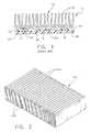
- FIG. 2is a perspective view of the heat sink member employed in the heat sink assembly of the present invention
- FIG. 3is a front view of the heat sink member of FIG. 2;
- FIG. 4is an exploded perspective view of the heat sink assembly of the present invention installed on a circuit board with a group of devices installed thereon;
- FIG. 5is a perspective view of the heat sink assembly of the present invention installed on a circuit board with a group of devices installed thereon;
- FIG. 6is a cross-sectional view through the line 6 - 6 of FIG. 5 and
- FIG. 7is an alternative embodiment of the heat sink assembly shown in FIG. 4 .
- a prior art heat sink assembly 10is shown to include a circuit board 12 and a number of devices 14 , 16 and 18 , to be cooled, which are installed thereon.
- a sample three component structure of devices 12 , 16 and 18are shown which are of three different heights while being simultaneously cooled by a single heat sink member 20 with a base 22 with a flat bottom 24 and upstanding fins 26 attached thereto.
- the top surfaces 14 a , 16 a and 18 a of the devices 14 , 16 and 18do not lie in the same plane thus they require some type of gap filling structure.
- a gap pad 28is provided in the prior art assembly of FIG. 1 whereby varying degrees of compression are employed to sufficiently bridge the three thermal gaps between each of the devices 14 , 16 and 18 to be cooled and the bottom surface 24 of the heat sink member 20 .
- the tallest device 14Since the leftmost device 14 is the tallest, the most compression is required of the gap pad 28 while the middle device 16 is the shortest requiring the least amount of compression to bridge the gap.
- the rightmost device 18is of middle height and the gap pad portion therebetween has a compression between the tallest device 14 and the shortest device 16 .
- the tallest device 14will achieve the best thermal transfer to the heat sink member 26 while the shortest device 16 will achieve the worst thermal transfer performance of the three.
- the prior art device 10 shown in FIG. 1is very heavy as it employs a block heat sink 20 extruded from aluminum stock.
- the interconnection between the heat sink member and the devices 14 , 16 and 18 to be cooledis not structurally strong thus risks separation during shipment and the like.
- the additional weightis unacceptable, particularly in laptop computers, where overall weight of the computer is of paramount concern.
- the heavy weight of the heat sink member 20make it top heavy thus placing stress on the gap pad joint, particularly where the prior art heat sink assembly 10 is vertically oriented, such as in a tower computer where the motherboard is vertically positioned.
- the heat dissipating member 102is preferably a corrugated member with an undulating structure creating a number of peaks 104 and valleys 106 where the bottoms of the valleys provide to contact points for installation to a base member as will be described in detail below.
- This heat dissipating member 102is preferably crimped or formed from a single sheet of thermally conductive material, such as aluminum of an approximate thickness of 20 mils.
- This member 102provides for a series of upstanding fin-like member to facilitate heat dissipation when in contact with ambient air.
- This heat dissipation member 102 employed in the assembly 100 of the present inventionis preferred in that it is very lightweight and easy and inexpensive to manufacture.
- the undulating construction shown in FIGS. 2 and 3is one of many different types of crimped or formed heat dissipating members 102 that are within the scope of the present invention.
- a triangular or sinusoidal wave(not shown) maybe employed depending on the application at hand.
- many different types of materialsmay be employed in addition to aluminum, such as copper.
- FIGS. 4-6The overall construction and installation of the assembly 100 of present invention on a circuit board is shown in FIGS. 4-6.
- FIG. 4a perspective view of the construction of the conforming heat sink assembly 100 of the present invention is shown.
- the heat dissipating member 102is bonded to a flexible base member 104 by thermally conductive epoxy 106 or the like. More specifically, the lower contact points 108 at the valleys of the heat dissipating member 102 are bonded to the top surface 110 of the flexible base member 104 .
- the flexible base member 104is, preferably, a sheet of thermally conductive material with an optimal thickness of approximately 100 mils.
- the conductive material for the flexible sheetis carbon-carbon matrix material for extremely high thermal conductivity.
- other flexible materials, such as conductive polymer compositesmay be employed for the base member 104 depending on the application.
- the heat sink assembly 100is preferably dimensioned to be large enough to cover the electronic components 112 , 114 and 116 to be cooled on a given circuit board 118 .
- the flexible base 104may be dimensioned to span underneath and contact all of the lower contacts points or valleys 108 of the heat dissipating member 102 .
- Such a large area heat sink assembly 100is easy to manufacture and requires little customization.
- the flexible base member 104may be cut into a specific footprint to match the pattern of heat generating devices 112 , 114 and 116 to be cooled to avoid excess material of the base member 104 .
- the heat dissipating member 102itself may be sized and cut into a specific footprint to match the layout of the devices 112 , 114 and 116 to be cooled.
- FIGS. 5 and 6illustrate actual installation of the heat sink assembly 100 of the present invention onto a number of devices 112 , 114 and 116 on a substrate 118 , such as a circuit board.
- FIG. 5shows a perspective view of the assembly 100 while FIG. 6 shows a cross-sectional view through the line 6 — 6 of FIG. 5 .
- FIGS. 5 and 6illustrate the preferred embodiment where the base member 104 and heat dissipating member 102 are not, for simplicity, cut to a specific footprint to the layout of the components 112 , 114 and 116 to be cooled.
- the flexible base 104 and heat dissipating member 102 bonded thereonare long and wide enough to cover all of the three devices 112 , 114 and 116 shown on the circuit board 118 .
- a layout of three devices 112 , 114 and 116are for illustration purposes only and any number of heat generating devices may be accommodated by the present invention.
- the heat dissipating member 102is bonded to the top surface 110 of the flexible base member 104 to provide the conforming heat sink assembly 100 of the present invention.
- the assembly 100is installed on the devices 112 , 114 and 116 to be cooled.
- a layer of bonding material 120such as pressure sensitive double-sided tape, is applied to the bottom 122 of the flexible base member 104 for bonding of the conforming heat sink assembly 100 to the top surfaces 112 a , 114 a and 116 a of the devices 112 , 114 and 116 to be cooled.
- the conforming assembly 100is placed over the devices 112 , 114 and 116 to be cooled and then pressed down into communication with the top surfaces 112 a , 114 a and 116 a of the devices 112 , 114 and 116 so that the bonding material 120 is engaged.
- the top portions or peaks 124 of the heat dissipating member 102are pressed downwardly so as to urge the bottom 122 of the flexible base member 104 into contact with each of the top surfaces 112 a , 114 a and 116 a of the devices 112 , 114 and 116 to be cooled, even when the devices 112 , 114 and 116 have different heights, as shown in FIGS. 4-6.
- the flexible base member 104conforms and adapts to the top surfaces 112 a , 114 a and 116 a of the devices 112 , 114 and 116 to be cooled.
- the heat dissipating member 102 of the present inventiondue to its undulating corrugated configuration, conforms to the flexible base member 104 thus providing uniform thermal transfer and dissipation from the devices 112 , 114 and 116 to be cooled.
- the heat dissipating member 202is preferably a corrugated member with an undulating structure creating a number of peaks 204 and valleys 208 where the bottoms of the valleys provide to contact points for installation into a base member as will be described in detail below.
- This heat dissipating member 202is preferably crimped or formed from a single sheet of thermally conductive material, such as aluminum of an approximate thickness of 20 mils.
- This member 202provides for a series of upstanding fin-like member to facilitate heat dissipation when in contact with ambient air.
- This heat dissipation member 202 employed in the assembly 200 of the present inventionis preferred in that it is very lightweight and easy and inexpensive to manufacture.
- the undulating construction of heat dissipating member 202is one of many different types of crimped or formed heat dissipating members that are within the scope of the present invention. For example, instead of the square wave configuration shown in FIG. 7, a triangular or sinusoidal wave (not shown) maybe employed depending on the application at hand. Further, many different types of materials may be employed in addition to aluminum, such as copper.
- the overall construction and installation of the assembly 200 of the alternative embodiment of the of present invention on a circuit boardis shown in FIG. 7 .
- the heat dissipating member 202is embedded directly into flexible base member 206 by insert molding the valleys 208 of heat dissipating member 202 directly into flexible base 206 . More specifically, the lower contact points 208 at the valleys of the heat dissipating member 202 are physically secured into flexible base member 204 . By such an insert molding connection, the lower contact points 208 are secured in thermally transfer communication with the flexible base 206 .
- the flexible base member 206is, preferably, a sheet of thermally conductive material with an optimal thickness of approximately 100 mils.
- the conductive material for the flexible sheetis carbon-carbon matrix material for extremely high thermal conductivity and which can be molded, such as by injection molding.
- other flexible materialssuch as conductive polymer composites, may be employed for the base member 206 depending on the application.
- the heat sink assembly 200is preferably dimensioned to be large enough to cover the electronic components 212 , 214 and 216 to be cooled on a given circuit board 218 .
- the flexible base 206may be dimensioned to span underneath and contact all of the lower contacts points or valleys 208 of the heat dissipating member 202 .
- Such a large area heat sink assembly 200is easy to manufacture and requires little customization.
- the flexible base member 206may be cut into a specific footprint to match the pattern of heat generating devices 212 , 214 and 216 to be cooled to avoid excess material of the base member 206 .
- the heat dissipating member 202itself may be sized and cut into a specific footprint to match the layout of the devices 212 , 214 and 216 to be cooled.
- the heat sink assembly of FIG. 7is affixed to a circuit board in similar fashion to the heat sink assembly of FIGS. 4-6.
- the heat dissipating member 202is bonded to the top surface 210 of the flexible base member 206 to provide the conforming heat sink assembly 200 of the present invention.
- the assembly 200is installed on the devices 212 , 214 and 216 to be cooled.
- a layer of bonding material 220such as pressure sensitive double-sided tape, is applied to the bottom 222 of the flexible base member 206 for bonding of the conforming heat sink assembly 200 to the top surfaces 212 a , 214 a and 216 a of the devices 212 , 214 and 216 to be cooled.
- the conforming assembly 100is placed over the devices 212 , 214 and 216 to be cooled and then pressed down into communication with the top surfaces 212 a , 214 a and 216 a of the devices 212 , 214 and 216 so that the bonding material 220 is engaged.
- the top portions or peaks 204 of the heat dissipating member 202are pressed downwardly so as to urge the bottom 222 of the flexible base member 206 into contact with each of the top surfaces 212 a , 214 a and 216 a of the devices 212 , 214 and 216 to be cooled, even when the devices 212 , 214 and 216 have different heights, as shown in FIGS. 4-6.
- the flexible base member 206conforms and adapts to the top surfaces 212 a , 214 a and 216 a of the devices 212 , 214 and 216 to be cooled.
- the heat dissipating member 202 of the present inventiondue to its undulating corrugated configuration, conforms to the flexible base member 206 thus providing uniform thermal transfer and dissipation from the devices 212 , 214 and 216 to be cooled.
- the alternative embodiment 200 of FIG. 7provides all of the advantages that the preferred embodiment 100 has over the prior art.
- the alternative embodiment 200 of FIG. 7provides a superior heat sink assembly 200 because of the unique connection of the heat dissipating member 202 and the flexible base 206 .
- the bottom portions or valleys 208 of the heat dissipating member 202are physically embedded or encapsulated within the body of the flexible base member 206 . This is accomplished during the molding or forming process of the base member 206 .
- Such an interconnectiongreatly reduces if not completely eliminates the junction resistance between the valleys 208 and the body of the flexible base 206 . More specifically, the contact resistance, conductive resistance and surface to air resistance are greatly reduced when the valleys 208 are embedded into flexible base 206 resulting in an overall system resistance that is less than prior art heat sink assemblies.
- the embedding of the fin structure, namely valleys 208 , within the flexible base 206 , as opposed to affixing the valleys 208 to the top surface 210 of the flexible base 206 ,provides a superior heat sink assembly 200 in that overall thermal conductivity and thermal efficiency is greatly improved.
- the present inventionprovides for a heat sink assembly that can provide uniform thermal transfer regardless of the height of the devices to be cooled in a construction that is easy and inexpensive to manufacture.
- the present inventionhas a wide range of applications and can be easily adapted for such applications.
- the present inventionmay be employed for any heat generating surface that is non-uniform.
- Further applicationsinclude any circuit board configuration where a heat generating device is provided on a circuit board.
- the present inventionmay be easily adapted to an application where the circuit board containing the heat generating device is encased in a housing, such as a Pentium II configuration. In this arrangement (not shown), the preferred embodiment may be easily modified to accommodate such a package.
Landscapes
- Engineering & Computer Science (AREA)
- Physics & Mathematics (AREA)
- Condensed Matter Physics & Semiconductors (AREA)
- General Physics & Mathematics (AREA)
- Computer Hardware Design (AREA)
- Microelectronics & Electronic Packaging (AREA)
- Power Engineering (AREA)
- Chemical & Material Sciences (AREA)
- Materials Engineering (AREA)
- Cooling Or The Like Of Semiconductors Or Solid State Devices (AREA)
- Cooling Or The Like Of Electrical Apparatus (AREA)
Abstract
Description
Claims (9)
Priority Applications (1)
| Application Number | Priority Date | Filing Date | Title |
|---|---|---|---|
| US09/850,017US6367541B2 (en) | 1999-05-06 | 2001-05-07 | Conforming heat sink assembly |
Applications Claiming Priority (2)
| Application Number | Priority Date | Filing Date | Title |
|---|---|---|---|
| US30609899A | 1999-05-06 | 1999-05-06 | |
| US09/850,017US6367541B2 (en) | 1999-05-06 | 2001-05-07 | Conforming heat sink assembly |
Related Parent Applications (1)
| Application Number | Title | Priority Date | Filing Date |
|---|---|---|---|
| US30609899AContinuation-In-Part | 1999-05-06 | 1999-05-06 |
Publications (2)
| Publication Number | Publication Date |
|---|---|
| US20010047858A1 US20010047858A1 (en) | 2001-12-06 |
| US6367541B2true US6367541B2 (en) | 2002-04-09 |
Family
ID=23183796
Family Applications (1)
| Application Number | Title | Priority Date | Filing Date |
|---|---|---|---|
| US09/850,017Expired - LifetimeUS6367541B2 (en) | 1999-05-06 | 2001-05-07 | Conforming heat sink assembly |
Country Status (1)
| Country | Link |
|---|---|
| US (1) | US6367541B2 (en) |
Cited By (50)
| Publication number | Priority date | Publication date | Assignee | Title |
|---|---|---|---|---|
| US20020195228A1 (en)* | 2001-06-07 | 2002-12-26 | International Business Machines Corporation | Thermal enhanced extended surface tape for integrated circuit heat dissipation |
| US6549411B1 (en)* | 2000-12-20 | 2003-04-15 | Edward Herbert | Flexible heat sinks and method of attaching flexible heat sinks |
| US20030121643A1 (en)* | 2002-01-03 | 2003-07-03 | Connors Matthew Joseph | Bi-level heat sink |
| US6614659B2 (en)* | 2001-12-07 | 2003-09-02 | Delphi Technologies, Inc. | De-mountable, solderless in-line lead module package with interface |
| US6654250B1 (en)* | 2002-09-25 | 2003-11-25 | International Business Machines Corporation | Low-stress compressive heatsink structure |
| US20040034345A1 (en)* | 2002-08-16 | 2004-02-19 | Lentz David J. | Heat transfer segment for a cryoablation catheter |
| US20040034344A1 (en)* | 2002-08-16 | 2004-02-19 | Eric Ryba | Tip pressure monitoring for cryoablation catheters |
| US20040182552A1 (en)* | 2001-07-31 | 2004-09-23 | Yoshinari Kubo | Heat sink for electronic devices and heat dissipating method |
| US6817096B2 (en)* | 2000-01-11 | 2004-11-16 | Cool Options, Inc. | Method of manufacturing a heat pipe construction |
| US20050039879A1 (en)* | 2003-08-05 | 2005-02-24 | Agilent Technologies, Inc. | Heat transmission member and an electronics device using the member |
| US20050077618A1 (en)* | 2002-12-19 | 2005-04-14 | 3M Innovative Properties Company | Flexible heat sink |
| US20050167082A1 (en)* | 2004-01-30 | 2005-08-04 | Datech Technology Co., Ltd. | Heat sink-type cooling device for an integrated circuit |
| US20050168941A1 (en)* | 2003-10-22 | 2005-08-04 | Sokol John L. | System and apparatus for heat removal |
| US20050274490A1 (en)* | 2001-06-05 | 2005-12-15 | Larson Ralph I | Heatsink assembly and method of manufacturing the same |
| US6999312B1 (en) | 2003-03-31 | 2006-02-14 | Sun Microsystems, Inc. | Heatsink apparatus |
| US7077858B2 (en) | 2003-09-22 | 2006-07-18 | Coolhead Technologies, Inc. | Flexible heat exchangers for medical cooling and warming applications |
| US20060191675A1 (en)* | 2003-09-22 | 2006-08-31 | Coolhead Technologies, Inc. | Apparatus and methods for warming and cooling bodies |
| US20060279936A1 (en)* | 2005-06-14 | 2006-12-14 | International Business Machines Corporation | Cooling structure using rigid movable elements |
| US20070062674A1 (en)* | 2005-03-18 | 2007-03-22 | Mitsubishi Electric Corporation | Cooling structure, heatsink and cooling method of heat generator |
| US20070076381A1 (en)* | 2005-08-18 | 2007-04-05 | Industrial Technology Research Institute | Flexible circuit board with heat sink |
| US20070159799A1 (en)* | 2007-01-09 | 2007-07-12 | Lockheed Martin Corporation | High Performance Large Tolerance Heat Sink |
| US20070267717A1 (en)* | 2006-05-22 | 2007-11-22 | Andrew Corporation | Coaxial RF Device Thermally Conductive Polymer Insulator and Method of Manufacture |
| US20080128113A1 (en)* | 2005-06-30 | 2008-06-05 | Kabushiki Kaisha Toshiba | Cooling device and electronic apparatus |
| US20080144292A1 (en)* | 2004-03-15 | 2008-06-19 | Hae-Hyung Lee | Semiconductor module with heat sink and method thereof |
| US20080197788A1 (en)* | 2006-11-28 | 2008-08-21 | Hayward Industries, Inc. | Programmable Underwater Lighting System |
| US20090126903A1 (en)* | 2006-04-24 | 2009-05-21 | Sumitomo Electric Industries, Ltd. | Heat transfer member, convex structural member, electronic apparatus, and electric product |
| US20100110627A1 (en)* | 2008-11-04 | 2010-05-06 | Hsing-Yu Chiang | Thermal module capable of dissipating heat generated by a plurality of heat sources and related computer system |
| US20110075377A1 (en)* | 2009-09-25 | 2011-03-31 | Raytheon Copany | Heat Sink Interface Having Three-Dimensional Tolerance Compensation |
| US20110316144A1 (en)* | 2010-06-25 | 2011-12-29 | Samsung Electronics Co., Ltd. | Flexible heat sink having ventilation ports and semiconductor package including the same |
| US8467191B2 (en) | 2010-12-02 | 2013-06-18 | Micron Technology, Inc. | Assemblies including heat sink elements and methods of assembling |
| US20130201630A1 (en)* | 2012-02-08 | 2013-08-08 | Foxconn Technology Co., Ltd. | Electronic deviec having heat dissipation device |
| US20170213451A1 (en) | 2016-01-22 | 2017-07-27 | Hayward Industries, Inc. | Systems and Methods for Providing Network Connectivity and Remote Monitoring, Optimization, and Control of Pool/Spa Equipment |
| US20170287809A1 (en)* | 2016-04-01 | 2017-10-05 | International Business Machines Corporation | Compliant pin fin heat sink with base integral pins |
| US10458717B2 (en)* | 2016-07-15 | 2019-10-29 | Magna Seating Inc | Flexible heat sink thermoelective device |
| US10718507B2 (en) | 2010-04-28 | 2020-07-21 | Hayard Industries, Inc. | Underwater light having a sealed polymer housing and method of manufacture therefor |
| US20200319621A1 (en) | 2016-01-22 | 2020-10-08 | Hayward Industries, Inc. | Systems and Methods for Providing Network Connectivity and Remote Monitoring, Optimization, and Control of Pool/Spa Equipment |
| USD903610S1 (en) | 2019-08-28 | 2020-12-01 | Carbice Corporation | Flexible heat sink |
| US10859330B1 (en) | 2019-08-28 | 2020-12-08 | Carbice Corporation | Flexible and conformable polymer-based heat sinks and methods of making and using thereof |
| USD904322S1 (en) | 2019-08-28 | 2020-12-08 | Carbice Corporation | Flexible heat sink |
| USD906269S1 (en) | 2019-08-28 | 2020-12-29 | Carbice Corporation | Flexible heat sink |
| US10976713B2 (en) | 2013-03-15 | 2021-04-13 | Hayward Industries, Inc. | Modular pool/spa control system |
| US11168876B2 (en) | 2019-03-06 | 2021-11-09 | Hayward Industries, Inc. | Underwater light having programmable controller and replaceable light-emitting diode (LED) assembly |
| US11230066B2 (en) | 2019-08-06 | 2022-01-25 | The Boeing Company | Induction welding using a heat sink and/or cooling |
| US11292204B2 (en) | 2019-08-06 | 2022-04-05 | The Boeing Company | Induction welding using a heat sink and/or cooling |
| US11351738B2 (en) | 2019-08-06 | 2022-06-07 | The Boeing Company | Induction welding using a heat sink and/or cooling |
| US11358344B2 (en) | 2019-08-06 | 2022-06-14 | The Boeiog Company | Induction welding using a heat sink and/or cooling |
| US11364688B2 (en)* | 2019-08-06 | 2022-06-21 | The Boeing Company | Induction welding using a heat sink and/or cooling |
| US11458691B2 (en) | 2019-08-06 | 2022-10-04 | The Boeing Company | Induction welding using a heat sink and/or cooling |
| US11524467B2 (en) | 2019-08-06 | 2022-12-13 | The Boeing Company | Induction welding using a heat sink and/or cooling |
| US12060989B2 (en) | 2019-03-06 | 2024-08-13 | Hayward Industries, Inc. | Underwater light having a replaceable light-emitting diode (LED) module and cord assembly |
Families Citing this family (8)
| Publication number | Priority date | Publication date | Assignee | Title |
|---|---|---|---|---|
| US20040008496A1 (en)* | 2002-07-10 | 2004-01-15 | Larson Thane Michael | Portable thermal barrier for an electronic system |
| US7391614B2 (en) | 2005-03-24 | 2008-06-24 | Dell Products L.P. | Method and apparatus for thermal dissipation in an information handling system |
| WO2007142273A1 (en)* | 2006-06-08 | 2007-12-13 | International Business Machines Corporation | Highly heat conductive, flexible sheet |
| US20090213548A1 (en)* | 2008-02-21 | 2009-08-27 | Kempers Roger S | Thermally conductive periodically structured gap fillers and method for utilizing same |
| CN103249278A (en)* | 2012-02-09 | 2013-08-14 | 富瑞精密组件(昆山)有限公司 | Heat dissipation device |
| GB2522642B (en) | 2014-01-30 | 2018-08-15 | Xyratex Tech Limited | A solid state memory unit cooling apparatus and solid state storage device |
| US10309473B2 (en)* | 2015-09-04 | 2019-06-04 | Edward D. Horton | Apparatus and method for heat dissipation of a brake pad |
| US12101913B2 (en)* | 2022-11-29 | 2024-09-24 | Dell Products L.P. | Variable topography heat sink fins |
Citations (9)
| Publication number | Priority date | Publication date | Assignee | Title |
|---|---|---|---|---|
| US2711382A (en)* | 1951-02-08 | 1955-06-21 | Gen Electric | Method of forming and applying metal heat exchange fins |
| US4964458A (en)* | 1986-04-30 | 1990-10-23 | International Business Machines Corporation | Flexible finned heat exchanger |
| US5168348A (en)* | 1991-07-15 | 1992-12-01 | International Business Machines Corporation | Impingment cooled compliant heat sink |
| US5653280A (en)* | 1995-11-06 | 1997-08-05 | Ncr Corporation | Heat sink assembly and method of affixing the same to electronic devices |
| US5771966A (en)* | 1995-12-15 | 1998-06-30 | Jacoby; John | Folded conducting member heatsinks and method of making same |
| US5829512A (en)* | 1995-08-29 | 1998-11-03 | Silicon Graphics, Inc. | Heatsink and method of forming a heatsink |
| US5837081A (en)* | 1993-04-07 | 1998-11-17 | Applied Sciences, Inc. | Method for making a carbon-carbon composite |
| US5894882A (en)* | 1993-02-19 | 1999-04-20 | Fujitsu Limited | Heat sink structure for cooling a substrate and an electronic apparatus having such a heat sink structure |
| US5912805A (en)* | 1998-11-04 | 1999-06-15 | Freuler; Raymond G. | Thermal interface with adhesive |
- 2001
- 2001-05-07USUS09/850,017patent/US6367541B2/ennot_activeExpired - Lifetime
Patent Citations (9)
| Publication number | Priority date | Publication date | Assignee | Title |
|---|---|---|---|---|
| US2711382A (en)* | 1951-02-08 | 1955-06-21 | Gen Electric | Method of forming and applying metal heat exchange fins |
| US4964458A (en)* | 1986-04-30 | 1990-10-23 | International Business Machines Corporation | Flexible finned heat exchanger |
| US5168348A (en)* | 1991-07-15 | 1992-12-01 | International Business Machines Corporation | Impingment cooled compliant heat sink |
| US5894882A (en)* | 1993-02-19 | 1999-04-20 | Fujitsu Limited | Heat sink structure for cooling a substrate and an electronic apparatus having such a heat sink structure |
| US5837081A (en)* | 1993-04-07 | 1998-11-17 | Applied Sciences, Inc. | Method for making a carbon-carbon composite |
| US5829512A (en)* | 1995-08-29 | 1998-11-03 | Silicon Graphics, Inc. | Heatsink and method of forming a heatsink |
| US5653280A (en)* | 1995-11-06 | 1997-08-05 | Ncr Corporation | Heat sink assembly and method of affixing the same to electronic devices |
| US5771966A (en)* | 1995-12-15 | 1998-06-30 | Jacoby; John | Folded conducting member heatsinks and method of making same |
| US5912805A (en)* | 1998-11-04 | 1999-06-15 | Freuler; Raymond G. | Thermal interface with adhesive |
Cited By (79)
| Publication number | Priority date | Publication date | Assignee | Title |
|---|---|---|---|---|
| US6817096B2 (en)* | 2000-01-11 | 2004-11-16 | Cool Options, Inc. | Method of manufacturing a heat pipe construction |
| US6549411B1 (en)* | 2000-12-20 | 2003-04-15 | Edward Herbert | Flexible heat sinks and method of attaching flexible heat sinks |
| US7284596B2 (en)* | 2001-06-05 | 2007-10-23 | Heat Technology, Inc. | Heatsink assembly and method of manufacturing the same |
| US20050274490A1 (en)* | 2001-06-05 | 2005-12-15 | Larson Ralph I | Heatsink assembly and method of manufacturing the same |
| US20050017350A1 (en)* | 2001-06-07 | 2005-01-27 | International Business Machines Corporation | Thermal enhanced extended surface tape for integrated circuit heat dissipation |
| US20020195228A1 (en)* | 2001-06-07 | 2002-12-26 | International Business Machines Corporation | Thermal enhanced extended surface tape for integrated circuit heat dissipation |
| US7128131B2 (en)* | 2001-07-31 | 2006-10-31 | The Furukawa Electric Co., Ltd. | Heat sink for electronic devices and heat dissipating method |
| US20040182552A1 (en)* | 2001-07-31 | 2004-09-23 | Yoshinari Kubo | Heat sink for electronic devices and heat dissipating method |
| US6614659B2 (en)* | 2001-12-07 | 2003-09-02 | Delphi Technologies, Inc. | De-mountable, solderless in-line lead module package with interface |
| US20060037735A1 (en)* | 2002-01-03 | 2006-02-23 | Connors Matthew J | Bi-level heat sink |
| US6966361B2 (en)* | 2002-01-03 | 2005-11-22 | Thermal Corp. | Bi-level heat sink |
| US20030121643A1 (en)* | 2002-01-03 | 2003-07-03 | Connors Matthew Joseph | Bi-level heat sink |
| US20040034345A1 (en)* | 2002-08-16 | 2004-02-19 | Lentz David J. | Heat transfer segment for a cryoablation catheter |
| US6955673B2 (en) | 2002-08-16 | 2005-10-18 | Cryocor, Inc. | Heat transfer segment for a cryoablation catheter |
| US20040034344A1 (en)* | 2002-08-16 | 2004-02-19 | Eric Ryba | Tip pressure monitoring for cryoablation catheters |
| US6654250B1 (en)* | 2002-09-25 | 2003-11-25 | International Business Machines Corporation | Low-stress compressive heatsink structure |
| US20050077618A1 (en)* | 2002-12-19 | 2005-04-14 | 3M Innovative Properties Company | Flexible heat sink |
| US7399919B2 (en)* | 2002-12-19 | 2008-07-15 | 3M Innovative Properties Company | Flexible heat sink |
| US6999312B1 (en) | 2003-03-31 | 2006-02-14 | Sun Microsystems, Inc. | Heatsink apparatus |
| US20050039879A1 (en)* | 2003-08-05 | 2005-02-24 | Agilent Technologies, Inc. | Heat transmission member and an electronics device using the member |
| US20060191675A1 (en)* | 2003-09-22 | 2006-08-31 | Coolhead Technologies, Inc. | Apparatus and methods for warming and cooling bodies |
| US7077858B2 (en) | 2003-09-22 | 2006-07-18 | Coolhead Technologies, Inc. | Flexible heat exchangers for medical cooling and warming applications |
| US20050168941A1 (en)* | 2003-10-22 | 2005-08-04 | Sokol John L. | System and apparatus for heat removal |
| US20050167082A1 (en)* | 2004-01-30 | 2005-08-04 | Datech Technology Co., Ltd. | Heat sink-type cooling device for an integrated circuit |
| US20080144292A1 (en)* | 2004-03-15 | 2008-06-19 | Hae-Hyung Lee | Semiconductor module with heat sink and method thereof |
| US20070062674A1 (en)* | 2005-03-18 | 2007-03-22 | Mitsubishi Electric Corporation | Cooling structure, heatsink and cooling method of heat generator |
| US8061412B2 (en)* | 2005-03-18 | 2011-11-22 | Mitsubishi Electric Corporation | Cooling structure, heatsink and cooling method of heat generator |
| US20060279936A1 (en)* | 2005-06-14 | 2006-12-14 | International Business Machines Corporation | Cooling structure using rigid movable elements |
| US7362582B2 (en)* | 2005-06-14 | 2008-04-22 | International Business Machines Corporation | Cooling structure using rigid movable elements |
| US20080128113A1 (en)* | 2005-06-30 | 2008-06-05 | Kabushiki Kaisha Toshiba | Cooling device and electronic apparatus |
| US7443678B2 (en)* | 2005-08-18 | 2008-10-28 | Industrial Technology Research Institute | Flexible circuit board with heat sink |
| US20070076381A1 (en)* | 2005-08-18 | 2007-04-05 | Industrial Technology Research Institute | Flexible circuit board with heat sink |
| US20090126903A1 (en)* | 2006-04-24 | 2009-05-21 | Sumitomo Electric Industries, Ltd. | Heat transfer member, convex structural member, electronic apparatus, and electric product |
| US20070267717A1 (en)* | 2006-05-22 | 2007-11-22 | Andrew Corporation | Coaxial RF Device Thermally Conductive Polymer Insulator and Method of Manufacture |
| US7705238B2 (en) | 2006-05-22 | 2010-04-27 | Andrew Llc | Coaxial RF device thermally conductive polymer insulator and method of manufacture |
| US9084314B2 (en) | 2006-11-28 | 2015-07-14 | Hayward Industries, Inc. | Programmable underwater lighting system |
| US20080197788A1 (en)* | 2006-11-28 | 2008-08-21 | Hayward Industries, Inc. | Programmable Underwater Lighting System |
| US7995344B2 (en) | 2007-01-09 | 2011-08-09 | Lockheed Martin Corporation | High performance large tolerance heat sink |
| US20070159799A1 (en)* | 2007-01-09 | 2007-07-12 | Lockheed Martin Corporation | High Performance Large Tolerance Heat Sink |
| US20100110627A1 (en)* | 2008-11-04 | 2010-05-06 | Hsing-Yu Chiang | Thermal module capable of dissipating heat generated by a plurality of heat sources and related computer system |
| US20110075377A1 (en)* | 2009-09-25 | 2011-03-31 | Raytheon Copany | Heat Sink Interface Having Three-Dimensional Tolerance Compensation |
| US8537552B2 (en)* | 2009-09-25 | 2013-09-17 | Raytheon Company | Heat sink interface having three-dimensional tolerance compensation |
| US10718507B2 (en) | 2010-04-28 | 2020-07-21 | Hayard Industries, Inc. | Underwater light having a sealed polymer housing and method of manufacture therefor |
| US20110316144A1 (en)* | 2010-06-25 | 2011-12-29 | Samsung Electronics Co., Ltd. | Flexible heat sink having ventilation ports and semiconductor package including the same |
| US8648478B2 (en)* | 2010-06-25 | 2014-02-11 | Samsung Electronics Co., Ltd. | Flexible heat sink having ventilation ports and semiconductor package including the same |
| US8467191B2 (en) | 2010-12-02 | 2013-06-18 | Micron Technology, Inc. | Assemblies including heat sink elements and methods of assembling |
| US9144149B2 (en) | 2010-12-02 | 2015-09-22 | Micron Technology, Inc. | Heat-dissipating assemblies and methods of assembling heat-dissipating assemblies |
| US8885346B2 (en)* | 2012-02-08 | 2014-11-11 | Foxconn Technology Co., Ltd. | Electronic deviec having heat dissipation device |
| US20130201630A1 (en)* | 2012-02-08 | 2013-08-08 | Foxconn Technology Co., Ltd. | Electronic deviec having heat dissipation device |
| US10976713B2 (en) | 2013-03-15 | 2021-04-13 | Hayward Industries, Inc. | Modular pool/spa control system |
| US11822300B2 (en) | 2013-03-15 | 2023-11-21 | Hayward Industries, Inc. | Modular pool/spa control system |
| US10363197B2 (en) | 2016-01-22 | 2019-07-30 | Hayward Industries, Inc. | Systems and methods for providing network connectivity and remote monitoring, optimization, and control of pool/spa equipment |
| US11122669B2 (en) | 2016-01-22 | 2021-09-14 | Hayward Industries, Inc. | Systems and methods for providing network connectivity and remote monitoring, optimization, and control of pool/spa equipment |
| US11720085B2 (en) | 2016-01-22 | 2023-08-08 | Hayward Industries, Inc. | Systems and methods for providing network connectivity and remote monitoring, optimization, and control of pool/spa equipment |
| US10219975B2 (en) | 2016-01-22 | 2019-03-05 | Hayward Industries, Inc. | Systems and methods for providing network connectivity and remote monitoring, optimization, and control of pool/spa equipment |
| US20200319621A1 (en) | 2016-01-22 | 2020-10-08 | Hayward Industries, Inc. | Systems and Methods for Providing Network Connectivity and Remote Monitoring, Optimization, and Control of Pool/Spa Equipment |
| US11129256B2 (en) | 2016-01-22 | 2021-09-21 | Hayward Industries, Inc. | Systems and methods for providing network connectivity and remote monitoring, optimization, and control of pool/spa equipment |
| US10272014B2 (en) | 2016-01-22 | 2019-04-30 | Hayward Industries, Inc. | Systems and methods for providing network connectivity and remote monitoring, optimization, and control of pool/spa equipment |
| US11096862B2 (en) | 2016-01-22 | 2021-08-24 | Hayward Industries, Inc. | Systems and methods for providing network connectivity and remote monitoring, optimization, and control of pool/spa equipment |
| US11000449B2 (en) | 2016-01-22 | 2021-05-11 | Hayward Industries, Inc. | Systems and methods for providing network connectivity and remote monitoring, optimization, and control of pool/spa equipment |
| US20170213451A1 (en) | 2016-01-22 | 2017-07-27 | Hayward Industries, Inc. | Systems and Methods for Providing Network Connectivity and Remote Monitoring, Optimization, and Control of Pool/Spa Equipment |
| US10991639B2 (en)* | 2016-04-01 | 2021-04-27 | International Business Machines Corporation | Compliant Pin Fin heat sink with base integral pins |
| US20170287809A1 (en)* | 2016-04-01 | 2017-10-05 | International Business Machines Corporation | Compliant pin fin heat sink with base integral pins |
| US10458717B2 (en)* | 2016-07-15 | 2019-10-29 | Magna Seating Inc | Flexible heat sink thermoelective device |
| US11754268B2 (en) | 2019-03-06 | 2023-09-12 | Hayward Industries, Inc. | Underwater light having programmable controller and replaceable light-emitting diode (LED) assembly |
| US12060989B2 (en) | 2019-03-06 | 2024-08-13 | Hayward Industries, Inc. | Underwater light having a replaceable light-emitting diode (LED) module and cord assembly |
| US12196401B2 (en) | 2019-03-06 | 2025-01-14 | Hayward Industries, Inc. | Underwater light having programmable controller and replaceable light-emitting diode (LED) assembly |
| US11168876B2 (en) | 2019-03-06 | 2021-11-09 | Hayward Industries, Inc. | Underwater light having programmable controller and replaceable light-emitting diode (LED) assembly |
| US11292204B2 (en) | 2019-08-06 | 2022-04-05 | The Boeing Company | Induction welding using a heat sink and/or cooling |
| US11351738B2 (en) | 2019-08-06 | 2022-06-07 | The Boeing Company | Induction welding using a heat sink and/or cooling |
| US11358344B2 (en) | 2019-08-06 | 2022-06-14 | The Boeiog Company | Induction welding using a heat sink and/or cooling |
| US11364688B2 (en)* | 2019-08-06 | 2022-06-21 | The Boeing Company | Induction welding using a heat sink and/or cooling |
| US11458691B2 (en) | 2019-08-06 | 2022-10-04 | The Boeing Company | Induction welding using a heat sink and/or cooling |
| US11524467B2 (en) | 2019-08-06 | 2022-12-13 | The Boeing Company | Induction welding using a heat sink and/or cooling |
| US11230066B2 (en) | 2019-08-06 | 2022-01-25 | The Boeing Company | Induction welding using a heat sink and/or cooling |
| USD906269S1 (en) | 2019-08-28 | 2020-12-29 | Carbice Corporation | Flexible heat sink |
| USD904322S1 (en) | 2019-08-28 | 2020-12-08 | Carbice Corporation | Flexible heat sink |
| US10859330B1 (en) | 2019-08-28 | 2020-12-08 | Carbice Corporation | Flexible and conformable polymer-based heat sinks and methods of making and using thereof |
| USD903610S1 (en) | 2019-08-28 | 2020-12-01 | Carbice Corporation | Flexible heat sink |
Also Published As
| Publication number | Publication date |
|---|---|
| US20010047858A1 (en) | 2001-12-06 |
Similar Documents
| Publication | Publication Date | Title |
|---|---|---|
| US6367541B2 (en) | Conforming heat sink assembly | |
| US6093961A (en) | Heat sink assembly manufactured of thermally conductive polymer material with insert molded metal attachment | |
| US6831836B2 (en) | Low thermal resistance interface for attachment of thermal materials to a processor die | |
| US6459582B1 (en) | Heatsink apparatus for de-coupling clamping forces on an integrated circuit package | |
| US6963130B1 (en) | Heatsinking and packaging of integrated circuit chips | |
| US6014315A (en) | Heat sink assembly with multiple pressure capability | |
| EP0871352B1 (en) | Integrated circuit device cooling structure | |
| US6252774B1 (en) | Multi-device heat sink assembly | |
| US6385047B1 (en) | U-shaped heat sink assembly | |
| US6385044B1 (en) | Heat pipe heat sink assembly for cooling semiconductor chips | |
| US6078500A (en) | Pluggable chip scale package | |
| US7606033B2 (en) | Mounting a heat sink in thermal contact with an electronic component | |
| US10342160B2 (en) | Heat sink attachment on existing heat sinks | |
| US5990552A (en) | Apparatus for attaching a heat sink to the back side of a flip chip package | |
| JP3147087B2 (en) | Stacked semiconductor device heat dissipation structure | |
| US5907474A (en) | Low-profile heat transfer apparatus for a surface-mounted semiconductor device employing a ball grid array (BGA) device package | |
| US7990717B2 (en) | Heat sink and electronic device using same | |
| US5737187A (en) | Apparatus, method and system for thermal management of an unpackaged semiconductor device | |
| EP0054539B1 (en) | A semiconductor integrated circuit device with an improved heat sink | |
| US20060221573A1 (en) | Heat sink for multiple semiconductor modules | |
| US20190132938A1 (en) | Floating core heat sink assembly | |
| US6972958B2 (en) | Multiple integrated circuit package module | |
| US20060060952A1 (en) | Heat spreader for non-uniform power dissipation | |
| US11810832B2 (en) | Heat sink configuration for multi-chip module | |
| US20020018338A1 (en) | Insert molded heat sink assembly |
Legal Events
| Date | Code | Title | Description |
|---|---|---|---|
| AS | Assignment | Owner name:COOL SHIELD, INC., RHODE ISLAND Free format text:ASSIGNMENT OF ASSIGNORS INTEREST;ASSIGNOR:COOL OPTIONS, INC.;REEL/FRAME:012343/0163 Effective date:20020123 | |
| STCF | Information on status: patent grant | Free format text:PATENTED CASE | |
| FEPP | Fee payment procedure | Free format text:PAT HOLDER CLAIMS SMALL ENTITY STATUS, ENTITY STATUS SET TO SMALL (ORIGINAL EVENT CODE: LTOS); ENTITY STATUS OF PATENT OWNER: LARGE ENTITY | |
| FPAY | Fee payment | Year of fee payment:4 | |
| FPAY | Fee payment | Year of fee payment:8 | |
| FPAY | Fee payment | Year of fee payment:12 | |
| AS | Assignment | Owner name:COOL OPTIONS, INC., NEW HAMPSHIRE Free format text:ASSIGNMENT OF ASSIGNORS INTEREST;ASSIGNOR:COOL SHIELD, INC.;REEL/FRAME:033960/0190 Effective date:20141010 | |
| AS | Assignment | Owner name:TICONA POLYMERS, INC., KENTUCKY Free format text:ASSIGNMENT OF ASSIGNORS INTEREST;ASSIGNOR:COOL OPTIONS, INC.;REEL/FRAME:034033/0088 Effective date:20141020 | |
| FEPP | Fee payment procedure | Free format text:PAT HOLDER NO LONGER CLAIMS SMALL ENTITY STATUS, ENTITY STATUS SET TO UNDISCOUNTED (ORIGINAL EVENT CODE: STOL); ENTITY STATUS OF PATENT OWNER: LARGE ENTITY |