US6367272B1 - Compressor capacity control system and method - Google Patents
Compressor capacity control system and methodDownload PDFInfo
- Publication number
- US6367272B1 US6367272B1US09/576,520US57652000AUS6367272B1US 6367272 B1US6367272 B1US 6367272B1US 57652000 AUS57652000 AUS 57652000AUS 6367272 B1US6367272 B1US 6367272B1
- Authority
- US
- United States
- Prior art keywords
- compressor
- capacity
- setting
- control
- air temperature
- Prior art date
- Legal status (The legal status is an assumption and is not a legal conclusion. Google has not performed a legal analysis and makes no representation as to the accuracy of the status listed.)
- Expired - Fee Related
Links
- 238000000034methodMethods0.000titleclaimsdescription19
- 230000004044responseEffects0.000claimsabstractdescription18
- 239000003570airSubstances0.000claimsdescription49
- 239000003507refrigerantSubstances0.000claimsdescription19
- 238000010438heat treatmentMethods0.000claimsdescription17
- 230000001351cycling effectEffects0.000claimsdescription14
- 238000004378air conditioningMethods0.000claimsdescription8
- 239000012080ambient airSubstances0.000claimsdescription6
- 230000009849deactivationEffects0.000claimsdescription6
- 238000001816coolingMethods0.000claimsdescription5
- 230000001419dependent effectEffects0.000claimsdescription2
- 230000003213activating effectEffects0.000claims1
- 239000000446fuelSubstances0.000description7
- 229920006395saturated elastomerPolymers0.000description7
- 239000007789gasSubstances0.000description6
- 230000007246mechanismEffects0.000description5
- 230000004913activationEffects0.000description4
- XAGFODPZIPBFFR-UHFFFAOYSA-NaluminiumChemical compound[Al]XAGFODPZIPBFFR-UHFFFAOYSA-N0.000description3
- 229910052782aluminiumInorganic materials0.000description3
- 238000002485combustion reactionMethods0.000description3
- 239000000463materialSubstances0.000description3
- 230000037361pathwayEffects0.000description3
- CURLTUGMZLYLDI-UHFFFAOYSA-NCarbon dioxideChemical compoundO=C=OCURLTUGMZLYLDI-UHFFFAOYSA-N0.000description2
- 230000008901benefitEffects0.000description2
- 230000000875corresponding effectEffects0.000description2
- 229920001971elastomerPolymers0.000description2
- 239000000203mixtureSubstances0.000description2
- 239000006227byproductSubstances0.000description1
- 229910002092carbon dioxideInorganic materials0.000description1
- 239000001569carbon dioxideSubstances0.000description1
- 230000008859changeEffects0.000description1
- 230000001276controlling effectEffects0.000description1
- 239000002826coolantSubstances0.000description1
- 230000002596correlated effectEffects0.000description1
- 230000008878couplingEffects0.000description1
- 238000010168coupling processMethods0.000description1
- 238000005859coupling reactionMethods0.000description1
- 230000007613environmental effectEffects0.000description1
- 230000006872improvementEffects0.000description1
- 230000004048modificationEffects0.000description1
- 238000012986modificationMethods0.000description1
- 230000008569processEffects0.000description1
- 230000001502supplementing effectEffects0.000description1
- 239000002918waste heatSubstances0.000description1
Images


Classifications
- B—PERFORMING OPERATIONS; TRANSPORTING
- B60—VEHICLES IN GENERAL
- B60H—ARRANGEMENTS OF HEATING, COOLING, VENTILATING OR OTHER AIR-TREATING DEVICES SPECIALLY ADAPTED FOR PASSENGER OR GOODS SPACES OF VEHICLES
- B60H1/00—Heating, cooling or ventilating [HVAC] devices
- B60H1/00642—Control systems or circuits; Control members or indication devices for heating, cooling or ventilating devices
- B60H1/00814—Control systems or circuits characterised by their output, for controlling particular components of the heating, cooling or ventilating installation
- B60H1/00878—Control systems or circuits characterised by their output, for controlling particular components of the heating, cooling or ventilating installation the components being temperature regulating devices
- B60H1/00899—Controlling the flow of liquid in a heat pump system
- B60H1/00907—Controlling the flow of liquid in a heat pump system where the flow direction of the refrigerant changes and an evaporator becomes condenser
- B—PERFORMING OPERATIONS; TRANSPORTING
- B60—VEHICLES IN GENERAL
- B60H—ARRANGEMENTS OF HEATING, COOLING, VENTILATING OR OTHER AIR-TREATING DEVICES SPECIALLY ADAPTED FOR PASSENGER OR GOODS SPACES OF VEHICLES
- B60H1/00—Heating, cooling or ventilating [HVAC] devices
- B60H1/32—Cooling devices
- B60H1/3204—Cooling devices using compression
- B60H1/3205—Control means therefor
- B60H1/3208—Vehicle drive related control of the compressor drive means, e.g. for fuel saving purposes
- F—MECHANICAL ENGINEERING; LIGHTING; HEATING; WEAPONS; BLASTING
- F25—REFRIGERATION OR COOLING; COMBINED HEATING AND REFRIGERATION SYSTEMS; HEAT PUMP SYSTEMS; MANUFACTURE OR STORAGE OF ICE; LIQUEFACTION SOLIDIFICATION OF GASES
- F25B—REFRIGERATION MACHINES, PLANTS OR SYSTEMS; COMBINED HEATING AND REFRIGERATION SYSTEMS; HEAT PUMP SYSTEMS
- F25B13/00—Compression machines, plants or systems, with reversible cycle
- F—MECHANICAL ENGINEERING; LIGHTING; HEATING; WEAPONS; BLASTING
- F25—REFRIGERATION OR COOLING; COMBINED HEATING AND REFRIGERATION SYSTEMS; HEAT PUMP SYSTEMS; MANUFACTURE OR STORAGE OF ICE; LIQUEFACTION SOLIDIFICATION OF GASES
- F25B—REFRIGERATION MACHINES, PLANTS OR SYSTEMS; COMBINED HEATING AND REFRIGERATION SYSTEMS; HEAT PUMP SYSTEMS
- F25B49/00—Arrangement or mounting of control or safety devices
- F25B49/02—Arrangement or mounting of control or safety devices for compression type machines, plants or systems
- F25B49/022—Compressor control arrangements
- B—PERFORMING OPERATIONS; TRANSPORTING
- B60—VEHICLES IN GENERAL
- B60H—ARRANGEMENTS OF HEATING, COOLING, VENTILATING OR OTHER AIR-TREATING DEVICES SPECIALLY ADAPTED FOR PASSENGER OR GOODS SPACES OF VEHICLES
- B60H1/00—Heating, cooling or ventilating [HVAC] devices
- B60H1/00642—Control systems or circuits; Control members or indication devices for heating, cooling or ventilating devices
- B60H1/00814—Control systems or circuits characterised by their output, for controlling particular components of the heating, cooling or ventilating installation
- B60H1/00878—Control systems or circuits characterised by their output, for controlling particular components of the heating, cooling or ventilating installation the components being temperature regulating devices
- B60H2001/00935—Control systems or circuits characterised by their output, for controlling particular components of the heating, cooling or ventilating installation the components being temperature regulating devices comprising four way valves for controlling the fluid direction
- B—PERFORMING OPERATIONS; TRANSPORTING
- B60—VEHICLES IN GENERAL
- B60H—ARRANGEMENTS OF HEATING, COOLING, VENTILATING OR OTHER AIR-TREATING DEVICES SPECIALLY ADAPTED FOR PASSENGER OR GOODS SPACES OF VEHICLES
- B60H1/00—Heating, cooling or ventilating [HVAC] devices
- B60H1/32—Cooling devices
- B60H2001/3236—Cooling devices information from a variable is obtained
- B60H2001/3248—Cooling devices information from a variable is obtained related to pressure
- B—PERFORMING OPERATIONS; TRANSPORTING
- B60—VEHICLES IN GENERAL
- B60H—ARRANGEMENTS OF HEATING, COOLING, VENTILATING OR OTHER AIR-TREATING DEVICES SPECIALLY ADAPTED FOR PASSENGER OR GOODS SPACES OF VEHICLES
- B60H1/00—Heating, cooling or ventilating [HVAC] devices
- B60H1/32—Cooling devices
- B60H2001/3236—Cooling devices information from a variable is obtained
- B60H2001/3255—Cooling devices information from a variable is obtained related to temperature
- B—PERFORMING OPERATIONS; TRANSPORTING
- B60—VEHICLES IN GENERAL
- B60H—ARRANGEMENTS OF HEATING, COOLING, VENTILATING OR OTHER AIR-TREATING DEVICES SPECIALLY ADAPTED FOR PASSENGER OR GOODS SPACES OF VEHICLES
- B60H1/00—Heating, cooling or ventilating [HVAC] devices
- B60H1/32—Cooling devices
- B60H2001/3269—Cooling devices output of a control signal
- B60H2001/327—Cooling devices output of a control signal related to a compressing unit
- B—PERFORMING OPERATIONS; TRANSPORTING
- B60—VEHICLES IN GENERAL
- B60H—ARRANGEMENTS OF HEATING, COOLING, VENTILATING OR OTHER AIR-TREATING DEVICES SPECIALLY ADAPTED FOR PASSENGER OR GOODS SPACES OF VEHICLES
- B60H1/00—Heating, cooling or ventilating [HVAC] devices
- B60H1/32—Cooling devices
- B60H2001/3286—Constructional features
- B60H2001/3294—Compressor drive is hybrid
- F—MECHANICAL ENGINEERING; LIGHTING; HEATING; WEAPONS; BLASTING
- F25—REFRIGERATION OR COOLING; COMBINED HEATING AND REFRIGERATION SYSTEMS; HEAT PUMP SYSTEMS; MANUFACTURE OR STORAGE OF ICE; LIQUEFACTION SOLIDIFICATION OF GASES
- F25B—REFRIGERATION MACHINES, PLANTS OR SYSTEMS; COMBINED HEATING AND REFRIGERATION SYSTEMS; HEAT PUMP SYSTEMS
- F25B2309/00—Gas cycle refrigeration machines
- F25B2309/06—Compression machines, plants or systems characterised by the refrigerant being carbon dioxide
- F—MECHANICAL ENGINEERING; LIGHTING; HEATING; WEAPONS; BLASTING
- F25—REFRIGERATION OR COOLING; COMBINED HEATING AND REFRIGERATION SYSTEMS; HEAT PUMP SYSTEMS; MANUFACTURE OR STORAGE OF ICE; LIQUEFACTION SOLIDIFICATION OF GASES
- F25B—REFRIGERATION MACHINES, PLANTS OR SYSTEMS; COMBINED HEATING AND REFRIGERATION SYSTEMS; HEAT PUMP SYSTEMS
- F25B2700/00—Sensing or detecting of parameters; Sensors therefor
- F25B2700/21—Temperatures
- F25B2700/2104—Temperatures of an indoor room or compartment
Definitions
- the present inventionis related to a HVAC system for use in an automobile.
- the HVAC systemuses a compressor capacity control that enhances the overall efficiency of the compressor operation.
- the HVAC system of an automobileutilizes a compressor that is either mechanically or electrically driven to circulate an automobile refrigerant to heat and or cool the interior passenger compartment of an automobile.
- the compressoris activated in response to a user demand such as a cooling request which will activate the compressor.
- the compressorwill be activated and/or deactivated in response to a user setting as well as a sensor placed within the vehicle compartment or in an appropriate location along the refrigerant line.
- the operation of the compressoris directly proportional to the speed (RPM) of the vehicles engine. Accordingly, there is no separate control of the compressors operation other than switching it on and off.
- the highest amount of demand required from the compressoris generally at times when the automobile is at idle (i.e. traffic jams and city driving conditions), and accordingly, the engine's speed is lowest.
- Another object of the present inventionis to provide a method and apparatus for improving the HVAC system of an automobile without affecting the energy load and accordingly the fuel efficiency of the automobile engine.
- FIG. 1is a diagrammatic view of a HVAC system
- FIG. 2is a diagrammatic view of a portion of the HVAC system illustrated in FIG. 1;
- FIG. 3is a diagrammatic view of a compressor and a compressor capacity control system
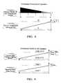
- FIG. 6is a chart illustrating compressor operational torque ranges at engine startup conditions
- FIG. 7is a chart illustrating the compressor clutches start-up characteristics
- FIG. 8illustrates compressor control for an air condition operation
- FIG. 9illustrates compressor control for an air condition operation
- FIG. 10illustrates compressor control for a heating operation
- HVAC system 10has a first heating loop 12 and a second heating loop 14 .
- First heating loop 12receives and circulates an engine coolant through a heater core 16 .
- Second heating loop 14provides heat and/or air conditioning to the vehicles interior through a cabin heat exchanger 18 .
- HVAC system 10receives an air input from a fresh air passage 20 and a recirculation air passage 22 .
- An air circulation door 24controls the mixture of the fresh to recirculation air that is inputted into the system.
- a blower or fan 26forces the fresh and/or recycled air into a main trunkline 28 that contains cabin heat exchanger 18 and heater core 16 .
- cabin heat exchanger 18manipulates the air flowing through heating system 10 in accordance with the system settings.
- Heater core 16is positioned down stream from cabin heat exchanger 18 .
- a blend door 30is positioned to direct the air to and/or away from heater core 16 after it has passed through cabin heat exchanger 18 .
- a mode door 32is positioned to direct the air or a portion thereof to a defog pathway 34 , a panel pathway 36 or a floor pathway 38 .
- HVAC loop 14heats and/or cools the air as it passes through trunkline 28 .
- a compressor 40receives an automobile refrigerant from an accumulator 42 .
- automobile refrigerantis an automobile refrigerant gas 134 A, however, other gases such as carbon dioxide, ect. can be used.
- conduit 44connects compressor 40 to accumulator 42 .
- conduit 44is 1 ⁇ 2′′ in diameter and is constructed out of a rubber material having flexible characteristics. The flexible characteristics of conduit 44 allow compressor 40 to vibrate in accordance with normal operation procedures without damaging conduit 46 and without transferring the vibration and noise to the other parts of the system or vehicle.
- Compressor 40receives and compresses the automobile refrigerant gas, which in accordance with Boyle's law, causes the temperature and pressure of the automobile refrigerant to increase. Once the temperature and pressure of the automobile refrigerant has been increased to the desired temperature and pressure the automobile refrigerant is transferred through a conduit 46 to a reverse flow valve 48 .
- the positioning of reverse flow valve 48determines the flow of automobile refrigerant gas through HVAC loop 14 . For example, if reverse flow valve 48 is set to a heating position the automobile refrigerant gas will flow in the direction of arrow 49 . Conversely, if reverse flow valve 48 is set to an air-conditioning positioned the gas will flow in the direction of arrow 51 .
- conduit 46is 3 ⁇ 8′′ in diameter and is also constructed out of a flexible material such as rubber.
- Reverse flow valve 48is also connected to a conduit 50 , a conduit 52 and a conduit 54 .
- Conduit 50is connected to reverse flow valve 48 at one end and accumulator 42 at the other.
- conduit 50is also 1 ⁇ 2 inch in diameter and is constructed out of aluminum.
- Conduit 52is connected to reverse flow valve 48 at one end and cabin heat exchanger 18 at the other.
- Conduit 54is connected to reverse flow valve 48 at one end and an outside heat exchanger 56 at the other end.
- conduits 52 and 54are 1 ⁇ 2 inch in diameter and are also constructed out of aluminum.
- a conduit 58is connected to cabin heat exchanger 18 at one end and outside heat exchanger 56 at the other.
- conduit 58is 3 ⁇ 8 of an inch in diameter and is also constructed out aluminum.
- An electronic expansion valve 60is positioned to provide a pressure drop that reduces the pressure of the automobile refrigerant and manage the flow rate of the refrigerant as it flows through conduit 58 .
- a high low-pressure switch 62is positioned to activate compressor 40 .
- Compressor 40is supplied with a mechanical operational force through the use of a clutch mechanism (not shown) that is coupled to the vehicles drivetrain.
- compressor 40can be driven by pair of pulleys and a belt wherein one of the pulleys is secured to the compressor and the other is secured to the vehicles engine or drivetrain.
- second heat loop 14receives some if not all of its required energy from the operational parts of the vehicle.
- compressor 40will derive its energy from an electrical source such as a battery.
- This batterymay be configured to receive a charge from a multipurpose unit (MPU) which is also configured to convert the mechanical force of the automobile's drivetrain into an electrical charge.
- MPUmultipurpose unit
- a thermal controller 66receives a climate control setting 68 and a system status 70 .
- Systems status 70is provided in the form of air temperature readings such as cabin temperature, ambient air temperature and the internal air temperature of the HVAC system.
- the aforementioned inputs in the form of air temperaturesis inputted into thermal controller 66 by a plurality of temperature sensors 71 which are appropriately located to provide the corresponding air temperature, namely, cabin temperature, ambient air temperature and HVAC system air temperature.
- the sensor that provides the HVAC system air temperatureis located within the ductwork of HVAC system 10 .
- Thermal controller 66in response to the climate control requests and the environmental status determines the operational configuration of compressor 40 .
- Compressor 40has a capacity control valve 72 that is manipulated in response to the inputs received by thermal controller 66 .
- Capacity control valve 72provides a means for adjusting the capacity of compressor 40 . For example, each revolution of compressor 40 will provide a known capacity in accordance with the setting of capacity control valve 72 .
- capacity control valve 72is an internal mechanical by-pass piston that is mechanically manipulated in response to commands received from thermal controller 66 .
- a clutch mechanism 74is coupled to the vehicles engine (not shown) through a pully and belt configuration (not shown) in order to provide a mechanical force for driving compressor 40 .
- compressor 40may be driven completely or in part by an electrical supply that is either provided by a generator and/or a battery system.
- a flowchartillustrates a command sequence 76 used by controller 66 in order to vary the setting of compressor control valve 72 in response to the temperature setting of the HVAC system.
- Command sequence 76may be performed by a computer algorithm which receives a plurality of inputs and in accordance with the value of these inputs, provides command requests to the automobiles HVAC system.
- An initial step 78receives the following inputs: temperature control setting (i.e. the requested operation cooling or heating and temperature setting); the ambient air temperature (the internal cabin temperature and/or the external and the air temperature); and the air temperature within the HVAC system.
- a second step or decision node 80determines whether the users selected temperature setting is less than current cabin temperature. If so, a third step 82 sets capacity control valve 72 in accordance with the climate control system setting. In addition, and as an alternative, the setting of capacity control valve 72 may be based in part upon the systems air temperatures such as, ambient air temperature, HVAC air temperature and cabin air temperature. If, on the other hand, the temperature setting is greater than the cabin temperature a request for activation of the heating system is made.
- a fourth step or decision node 84determines the current compressor status (i.e. on/off). If the compressor is off a fifth step or decision node 86 determines if the temperature setting is less than the HVAC air temperature. If yes, the compressor is activated and the compressor capacity valve is appropriately set (sixth step 88 ) in accordance with the temperature request.
- a sixth step 88modifies the compressor capacity valve in accordance with the requested setting.
- the airflow temperature in the HVAC unitis a controlled variable that determines the actuation of the compressor clutch.
- the low-pressure set point of the compressor control valvevaries with either the ambient air temperature or a prescribed temperature difference based upon ambient temperature for heat pump (heating).
- the compressor of prior systemseither cycles on and off in response to an air conditioning request.
- the air-conditioning systemmay in response to an air-conditioning command request can over cool the air which in turn requires the automobiles heating system (utilizing either waste heat from the engine core or a heat pump system) in order to reheat the over cooled air.
- the automobiles heating systemutilizing either waste heat from the engine core or a heat pump system
- This processresults in an inefficient use of the vehicles power system.
- the heat pump systemis used, and excessive amount of loading is applied to the vehicles electrical supply.
- a minimum time constant of three secondsis used to define the period for which the capacity of compressor 40 may be increased from a minimum of 30% to a maximum of 100%.
- a deactivation time constantis used to limit the cycling (off/on) of the compressor, namely, the mechanical coupling of compressor 40 to the vehicles power supply and/or powertrain via a clutch mechanism or electrical source.
- the deactivation time constantis at least 20 seconds. Therefore, the cycling or time interval in between the activation/deactivation of the compressor is at least 20 seconds. Of course it is contemplated in accordance with the instant application the time interval may be varied to be either greater or less than 20 seconds.
- the cycling and resetting of the compressorsubstantially contributes to be overall efficiency of the internal combustion engine as well as the initial loading upon the same. Accordingly, and in a hybrid mode or engine mode the engine speed varies in accordance with the torque commands, therefore, the capacity of the compressor is varied in accordance with the control setting in order to accommodate the variations of the engine speed into the capacity of the compressor.
- a chart 90illustrates the compressor operating torque range at normal operation conditions.
- the maximum torque curveillustrates a compressor wherein the compressor capacity control valve is at 100%.
- the minimum torque curveillustrates compressor operation wherein the compressor capacity control valve is at 30%.
- a chart 92illustrates the compressor operating torque range at startup conditions.
- the maximum torque curveillustrates a compressor wherein the compressor capacity control valve is at 100% while the minimum torque curve illustrates a compressor capacity control valve setting of 30%.
- a chart 94illustrates the compressor startup characteristics as a function of current draw with respect to time.
- the compressor capacityis altered to provide the most efficient operation of the same.
- the setting value of suction pressureis determined by an embedded control algorithm and carried out by capacity control valve (CCV) 72 .
- the CCVconsists of a stepping motor and valve elements, which is designed to promptly change compressor capacity in response to the external demands. There is a power saving feature in the CCV design. Power is consumed only when the stepping motor is energized to drive the CCV to a new position; no power is required after the target position has been achieved.
- Operating the CCVestablishes a control baseline for the suction pressure setting. This setting value is a function of ambient conditions and the selections of operators.
- the saturated refrigerant pressureshould be set to 0.243 Mpa or the saturated refrigerant temperature should be set to ⁇ 5 C.
- the CCVshould be driven by the stepping motor to a certain position.
- the controller or the control algorithmshould send a command (pulse count) to the stepping motor so that the stepping motor drives the valve mechanism to a certain position.
- FIGS. 10 and 11show the logic linkage from the customer selection (stage 1 to stage 5 ) on the heating temperature control, to duct discharge air temperature settings (35 C to 65 C, linearly).
- the saturated refrigerant pressure or temperatureis correlated to the ambient temperature condition since the ambient temperature is a major limit factor to the heat pump operation.
- the pulse count from the controller to the stepping motoris determined by the ambient temperature, as indicated in FIGS. 10 and 11.
- Compressor capacity controlresponds to the suction pressure setting
Landscapes
- Engineering & Computer Science (AREA)
- Physics & Mathematics (AREA)
- Thermal Sciences (AREA)
- Mechanical Engineering (AREA)
- General Engineering & Computer Science (AREA)
- Air-Conditioning For Vehicles (AREA)
Abstract
Description
Claims (16)
Priority Applications (1)
| Application Number | Priority Date | Filing Date | Title |
|---|---|---|---|
| US09/576,520US6367272B1 (en) | 1999-12-29 | 2000-05-23 | Compressor capacity control system and method |
Applications Claiming Priority (2)
| Application Number | Priority Date | Filing Date | Title |
|---|---|---|---|
| US17344999P | 1999-12-29 | 1999-12-29 | |
| US09/576,520US6367272B1 (en) | 1999-12-29 | 2000-05-23 | Compressor capacity control system and method |
Publications (1)
| Publication Number | Publication Date |
|---|---|
| US6367272B1true US6367272B1 (en) | 2002-04-09 |
Family
ID=26869163
Family Applications (1)
| Application Number | Title | Priority Date | Filing Date |
|---|---|---|---|
| US09/576,520Expired - Fee RelatedUS6367272B1 (en) | 1999-12-29 | 2000-05-23 | Compressor capacity control system and method |
Country Status (1)
| Country | Link |
|---|---|
| US (1) | US6367272B1 (en) |
Cited By (22)
| Publication number | Priority date | Publication date | Assignee | Title |
|---|---|---|---|---|
| US6588222B1 (en)* | 2002-05-08 | 2003-07-08 | Delphi Technologies, Inc. | Low-cost energy-efficient vehicle air conditioning system |
| US6652240B2 (en)* | 2001-08-20 | 2003-11-25 | Scales Air Compressor | Method and control system for controlling multiple throttled inlet rotary screw compressors |
| WO2004005807A1 (en)* | 2002-07-02 | 2004-01-15 | Delphi Technologies, Inc. | Air conditioning system |
| US20040144107A1 (en)* | 2003-01-27 | 2004-07-29 | Matthew Breton | HVAC controls for a vehicle with start-stop engine operation |
| EP1479546A1 (en)* | 2003-05-23 | 2004-11-24 | Behr GmbH & Co. KG | Method and device for controlling a heat exchanging equipment |
| US20080223067A1 (en)* | 2007-03-12 | 2008-09-18 | Samsung Electronics Co., Ltd. | Fuel cell system and air conditioner using the same |
| US20110082594A1 (en)* | 2009-10-07 | 2011-04-07 | Ford Global Technologies, Llc | Climate Control System And Method For Optimizing Energy Consumption of A Vehicle |
| US20110088869A1 (en)* | 2009-10-13 | 2011-04-21 | Carrier Corporation | Heat treating a dairy product using a heat pump |
| US20120089256A1 (en)* | 2010-10-12 | 2012-04-12 | Engineered Electric Company | Portable cogeneration system incorporating renewable energy soures |
| US20120291467A1 (en)* | 2011-05-20 | 2012-11-22 | Denso Corporation | Refrigerant cycle device |
| RU2613662C2 (en)* | 2011-11-30 | 2017-03-21 | ФОРД ГЛОУБАЛ ТЕКНОЛОДЖИЗ, ЭлЭлСи | Hvac unit for air treatment in vehicle passenger cabin, method of measuring climatic characteristic of internal air in vehicle passenger cabin and hvac unit in vehicle passenger cabin |
| US20170282675A1 (en)* | 2015-12-22 | 2017-10-05 | Uber Technologies, Inc. | Thermal reduction system for an autonomous vehicle |
| WO2018123636A1 (en)* | 2016-12-27 | 2018-07-05 | サンデン・オートモーティブクライメイトシステム株式会社 | Vehicle air-conditioning apparatus |
| US20190061473A1 (en)* | 2017-08-25 | 2019-02-28 | Thermo King Corporation | Method and system for adaptive power engine control |
| CN109910557A (en)* | 2019-03-04 | 2019-06-21 | 青岛海尔空调器有限总公司 | Control method of vehicle air conditioner |
| US11002453B2 (en)* | 2018-05-16 | 2021-05-11 | Johnson Controls Technology Company | HVAC functionality restoration systems and methods |
| US11126165B2 (en) | 2020-02-11 | 2021-09-21 | Uatc, Llc | Vehicle computing system cooling systems |
| US11407283B2 (en) | 2018-04-30 | 2022-08-09 | Tiger Tool International Incorporated | Cab heating systems and methods for vehicles |
| US11430331B2 (en) | 2017-09-08 | 2022-08-30 | Uatc, Llc | Power and thermal management systems and methods for autonomous vehicles |
| CN115127267A (en)* | 2022-05-26 | 2022-09-30 | 浙江青风环境股份有限公司 | A high temperature heat pump unit control system and control method |
| US11993130B2 (en) | 2018-11-05 | 2024-05-28 | Tiger Tool International Incorporated | Cooling systems and methods for vehicle cabs |
| US12030368B2 (en) | 2020-07-02 | 2024-07-09 | Tiger Tool International Incorporated | Compressor systems and methods for use by vehicle heating, ventilating, and air conditioning systems |
Citations (10)
| Publication number | Priority date | Publication date | Assignee | Title |
|---|---|---|---|---|
| US4698977A (en)* | 1984-11-12 | 1987-10-13 | Diesel Kiki Co., Ltd. | Air conditioning system for automotive vehicles |
| US5014522A (en)* | 1989-04-29 | 1991-05-14 | Nissan Motor Co., Ltd. | Automotive air tempering apparatus |
| US5018366A (en)* | 1988-02-05 | 1991-05-28 | Kabushiki Kaisha Toyoda Jidoshokki Seisakusho | Control circuit unit for a variable capacity compressor incorporating a solenoid-operated capacity control valve |
| US5117643A (en)* | 1990-01-24 | 1992-06-02 | Zexel Corp. | Automobile air-conditioner |
| US5142881A (en)* | 1990-03-31 | 1992-09-01 | Mazda Motor Corporation | Automobile air conditioning system |
| US5653119A (en)* | 1994-05-27 | 1997-08-05 | Kabushiki Kaisha Toyoda Jidoshokki Seisakusho | Refrigerating system incorporating therein a variable capacity refrigerant compressor |
| US5884497A (en)* | 1997-06-17 | 1999-03-23 | Denso Corporation | Automotive air conditioner |
| US5979168A (en)* | 1997-07-15 | 1999-11-09 | American Standard Inc. | Single-source gas actuation for screw compressor slide valve assembly |
| US6145329A (en)* | 1998-11-23 | 2000-11-14 | General Motors Corporation | Method for the control of the switching on and off behavior of an air conditioning system |
| US6233957B1 (en)* | 1999-06-07 | 2001-05-22 | Mitsubishi Heavy Industries, Ltd. | Vehicular air conditioner |
- 2000
- 2000-05-23USUS09/576,520patent/US6367272B1/ennot_activeExpired - Fee Related
Patent Citations (11)
| Publication number | Priority date | Publication date | Assignee | Title |
|---|---|---|---|---|
| US4698977A (en)* | 1984-11-12 | 1987-10-13 | Diesel Kiki Co., Ltd. | Air conditioning system for automotive vehicles |
| US4748819A (en)* | 1984-11-12 | 1988-06-07 | Diesel Kiki Co., Ltd. | Air conditioning system for automotive vehicles |
| US5018366A (en)* | 1988-02-05 | 1991-05-28 | Kabushiki Kaisha Toyoda Jidoshokki Seisakusho | Control circuit unit for a variable capacity compressor incorporating a solenoid-operated capacity control valve |
| US5014522A (en)* | 1989-04-29 | 1991-05-14 | Nissan Motor Co., Ltd. | Automotive air tempering apparatus |
| US5117643A (en)* | 1990-01-24 | 1992-06-02 | Zexel Corp. | Automobile air-conditioner |
| US5142881A (en)* | 1990-03-31 | 1992-09-01 | Mazda Motor Corporation | Automobile air conditioning system |
| US5653119A (en)* | 1994-05-27 | 1997-08-05 | Kabushiki Kaisha Toyoda Jidoshokki Seisakusho | Refrigerating system incorporating therein a variable capacity refrigerant compressor |
| US5884497A (en)* | 1997-06-17 | 1999-03-23 | Denso Corporation | Automotive air conditioner |
| US5979168A (en)* | 1997-07-15 | 1999-11-09 | American Standard Inc. | Single-source gas actuation for screw compressor slide valve assembly |
| US6145329A (en)* | 1998-11-23 | 2000-11-14 | General Motors Corporation | Method for the control of the switching on and off behavior of an air conditioning system |
| US6233957B1 (en)* | 1999-06-07 | 2001-05-22 | Mitsubishi Heavy Industries, Ltd. | Vehicular air conditioner |
Cited By (35)
| Publication number | Priority date | Publication date | Assignee | Title |
|---|---|---|---|---|
| US6652240B2 (en)* | 2001-08-20 | 2003-11-25 | Scales Air Compressor | Method and control system for controlling multiple throttled inlet rotary screw compressors |
| US6588222B1 (en)* | 2002-05-08 | 2003-07-08 | Delphi Technologies, Inc. | Low-cost energy-efficient vehicle air conditioning system |
| WO2004005807A1 (en)* | 2002-07-02 | 2004-01-15 | Delphi Technologies, Inc. | Air conditioning system |
| US20050198980A1 (en)* | 2002-07-02 | 2005-09-15 | Cowell Timothy A. | Air conditioning system |
| US20040144107A1 (en)* | 2003-01-27 | 2004-07-29 | Matthew Breton | HVAC controls for a vehicle with start-stop engine operation |
| EP1479546A1 (en)* | 2003-05-23 | 2004-11-24 | Behr GmbH & Co. KG | Method and device for controlling a heat exchanging equipment |
| US20080223067A1 (en)* | 2007-03-12 | 2008-09-18 | Samsung Electronics Co., Ltd. | Fuel cell system and air conditioner using the same |
| EP1970987A3 (en)* | 2007-03-12 | 2009-06-10 | Samsung Electronics Co., Ltd. | Fuel cell system and air conditioner using the same |
| US20110082594A1 (en)* | 2009-10-07 | 2011-04-07 | Ford Global Technologies, Llc | Climate Control System And Method For Optimizing Energy Consumption of A Vehicle |
| US8249749B2 (en) | 2009-10-07 | 2012-08-21 | Ford Global Technologies, Llc | Climate control system and method for optimizing energy consumption of a vehicle |
| US20110088869A1 (en)* | 2009-10-13 | 2011-04-21 | Carrier Corporation | Heat treating a dairy product using a heat pump |
| US20120089256A1 (en)* | 2010-10-12 | 2012-04-12 | Engineered Electric Company | Portable cogeneration system incorporating renewable energy soures |
| US8812164B2 (en)* | 2010-10-12 | 2014-08-19 | Engineered Electric Company | Portable cogeneration system incorporating renewable energy sources |
| US9803904B2 (en)* | 2011-05-20 | 2017-10-31 | Denso Corporation | Refrigerant cycle device |
| US20120291467A1 (en)* | 2011-05-20 | 2012-11-22 | Denso Corporation | Refrigerant cycle device |
| RU2613662C2 (en)* | 2011-11-30 | 2017-03-21 | ФОРД ГЛОУБАЛ ТЕКНОЛОДЖИЗ, ЭлЭлСи | Hvac unit for air treatment in vehicle passenger cabin, method of measuring climatic characteristic of internal air in vehicle passenger cabin and hvac unit in vehicle passenger cabin |
| US20170282675A1 (en)* | 2015-12-22 | 2017-10-05 | Uber Technologies, Inc. | Thermal reduction system for an autonomous vehicle |
| WO2018123636A1 (en)* | 2016-12-27 | 2018-07-05 | サンデン・オートモーティブクライメイトシステム株式会社 | Vehicle air-conditioning apparatus |
| US20190061473A1 (en)* | 2017-08-25 | 2019-02-28 | Thermo King Corporation | Method and system for adaptive power engine control |
| US11097600B2 (en)* | 2017-08-25 | 2021-08-24 | Thermo King Corporation | Method and system for adaptive power engine control |
| US11842639B2 (en) | 2017-09-08 | 2023-12-12 | Uatc, Llc | Power and thermal management systems and methods for autonomous vehicles |
| US11430331B2 (en) | 2017-09-08 | 2022-08-30 | Uatc, Llc | Power and thermal management systems and methods for autonomous vehicles |
| US12437636B2 (en) | 2017-09-08 | 2025-10-07 | Aurora Operations, Inc. | Power and thermal management systems and methods for autonomous vehicles |
| US11407283B2 (en) | 2018-04-30 | 2022-08-09 | Tiger Tool International Incorporated | Cab heating systems and methods for vehicles |
| US11002453B2 (en)* | 2018-05-16 | 2021-05-11 | Johnson Controls Technology Company | HVAC functionality restoration systems and methods |
| US11686490B2 (en) | 2018-05-16 | 2023-06-27 | Johnson Controls Tyco IP Holdings LLP | HVAC functionality restoration systems and methods |
| US11993130B2 (en) | 2018-11-05 | 2024-05-28 | Tiger Tool International Incorporated | Cooling systems and methods for vehicle cabs |
| CN109910557A (en)* | 2019-03-04 | 2019-06-21 | 青岛海尔空调器有限总公司 | Control method of vehicle air conditioner |
| CN109910557B (en)* | 2019-03-04 | 2021-10-29 | 青岛海尔空调器有限总公司 | Control method of vehicle air conditioner |
| US11537106B2 (en) | 2020-02-11 | 2022-12-27 | Uatc, Llc | Vehicle computing system cooling systems |
| US11287806B2 (en) | 2020-02-11 | 2022-03-29 | Uatc, Llc | Vehicle computing system cooling systems |
| US11126165B2 (en) | 2020-02-11 | 2021-09-21 | Uatc, Llc | Vehicle computing system cooling systems |
| US12030368B2 (en) | 2020-07-02 | 2024-07-09 | Tiger Tool International Incorporated | Compressor systems and methods for use by vehicle heating, ventilating, and air conditioning systems |
| CN115127267A (en)* | 2022-05-26 | 2022-09-30 | 浙江青风环境股份有限公司 | A high temperature heat pump unit control system and control method |
| CN115127267B (en)* | 2022-05-26 | 2024-05-28 | 浙江青风环境股份有限公司 | A high temperature heat pump unit control system and control method |
Similar Documents
| Publication | Publication Date | Title |
|---|---|---|
| US6367272B1 (en) | Compressor capacity control system and method | |
| US6515448B2 (en) | Air conditioner for hybrid vehicle | |
| US6516621B2 (en) | Air conditioner for hybrid vehicle | |
| US7152417B2 (en) | Battery cooling apparatus with sufficient cooling capacity | |
| US7325595B2 (en) | Automotive air conditioning system | |
| US8047274B2 (en) | Air conditioner for vehicle | |
| US6817330B1 (en) | Internal combustion engine control apparatus | |
| US7007856B2 (en) | Extended engine off passenger climate control system and method | |
| JP2004147379A (en) | Air-conditioner for hybrid car | |
| JP4548480B2 (en) | Air conditioner for hybrid vehicles | |
| CN107284440B (en) | Engine starting method for hybrid vehicle | |
| US10953725B2 (en) | Method and system for heating a vehicle | |
| US6874330B2 (en) | Air conditioner for hybrid vehicle | |
| JP3432232B2 (en) | Air conditioner for hybrid vehicle | |
| US6598671B1 (en) | Hybrid heating system and method for vehicles | |
| US6659727B2 (en) | Control method for a dual mode compressor drive system | |
| JP3791234B2 (en) | Air conditioner for hybrid vehicles. | |
| JP2004066847A (en) | Air conditioner for vehicle | |
| EP1308327A2 (en) | Energy efficient control method for a manually regulated vehicle heating and air conditioning system | |
| JP4435350B2 (en) | Air conditioner for vehicles | |
| JP5381082B2 (en) | Air conditioner for vehicles | |
| JP5920183B2 (en) | Control device for internal combustion engine | |
| JPH11151932A (en) | Hybrid vehicle air conditioner | |
| JP5012786B2 (en) | Air conditioner for vehicles | |
| JP3936200B2 (en) | Air conditioner for vehicles |
Legal Events
| Date | Code | Title | Description |
|---|---|---|---|
| AS | Assignment | Owner name:GENERAL MOTORS CORPORATION, MICHIGAN Free format text:ASSIGNMENT OF ASSIGNORS INTEREST;ASSIGNORS:ZENG, ZIN;MAJOR, GREGORY ALAN;HIRAO, TOYOTAKA;REEL/FRAME:010845/0456 Effective date:20000523 | |
| FPAY | Fee payment | Year of fee payment:4 | |
| AS | Assignment | Owner name:GM GLOBAL TECHNOLOGY OPERATIONS, INC., MICHIGAN Free format text:ASSIGNMENT OF ASSIGNORS INTEREST;ASSIGNOR:GENERAL MOTORS CORPORATION;REEL/FRAME:022092/0755 Effective date:20050119 Owner name:GM GLOBAL TECHNOLOGY OPERATIONS, INC.,MICHIGAN Free format text:ASSIGNMENT OF ASSIGNORS INTEREST;ASSIGNOR:GENERAL MOTORS CORPORATION;REEL/FRAME:022092/0755 Effective date:20050119 | |
| AS | Assignment | Owner name:UNITED STATES DEPARTMENT OF THE TREASURY, DISTRICT Free format text:SECURITY AGREEMENT;ASSIGNOR:GM GLOBAL TECHNOLOGY OPERATIONS, INC.;REEL/FRAME:022201/0501 Effective date:20081231 | |
| AS | Assignment | Owner name:CITICORP USA, INC. AS AGENT FOR HEDGE PRIORITY SEC Free format text:SECURITY AGREEMENT;ASSIGNOR:GM GLOBAL TECHNOLOGY OPERATIONS, INC.;REEL/FRAME:022556/0013 Effective date:20090409 Owner name:CITICORP USA, INC. AS AGENT FOR BANK PRIORITY SECU Free format text:SECURITY AGREEMENT;ASSIGNOR:GM GLOBAL TECHNOLOGY OPERATIONS, INC.;REEL/FRAME:022556/0013 Effective date:20090409 | |
| AS | Assignment | Owner name:GM GLOBAL TECHNOLOGY OPERATIONS, INC., MICHIGAN Free format text:RELEASE BY SECURED PARTY;ASSIGNOR:UNITED STATES DEPARTMENT OF THE TREASURY;REEL/FRAME:023238/0015 Effective date:20090709 | |
| XAS | Not any more in us assignment database | Free format text:RELEASE BY SECURED PARTY;ASSIGNOR:UNITED STATES DEPARTMENT OF THE TREASURY;REEL/FRAME:023124/0383 | |
| AS | Assignment | Owner name:GM GLOBAL TECHNOLOGY OPERATIONS, INC., MICHIGAN Free format text:RELEASE BY SECURED PARTY;ASSIGNORS:CITICORP USA, INC. AS AGENT FOR BANK PRIORITY SECURED PARTIES;CITICORP USA, INC. AS AGENT FOR HEDGE PRIORITY SECURED PARTIES;REEL/FRAME:023127/0326 Effective date:20090814 | |
| REMI | Maintenance fee reminder mailed | ||
| LAPS | Lapse for failure to pay maintenance fees | ||
| STCH | Information on status: patent discontinuation | Free format text:PATENT EXPIRED DUE TO NONPAYMENT OF MAINTENANCE FEES UNDER 37 CFR 1.362 | |
| FP | Expired due to failure to pay maintenance fee | Effective date:20100409 |